


LNC-M520i
Operator’s Manual
2008/1 Ver V04.00.001(4408210025)
Leading Numerical Controller
LNC Technology Co., Ltd.

 LNC-M520i
Table of Content
Table of Content
1 |
GENERAL ............................................................................................... |
1 |
||
|
1.1 |
HARDWARE SPECIFICATION ................................................................................... |
2 |
|
|
1.2 |
SOFTWARE SPECIFICATION ................................................................................... |
3 |
|
|
1.3 |
SYSTEM SETTING UNIT ......................................................................................... |
4 |
|
|
1.4 |
G CODE TABLE .................................................................................................... |
5 |
|
2 |
CNC OPERATION ................................................................................... |
8 |
||
|
2.1 |
OPERATION DEVICES TYPE ................................................................................... |
8 |
|
|
2.2 |
OPERATION DEVICES INTRODUCE .......................................................................... |
9 |
|
|
2.3 |
SCREEN AND FUNCTION DESCRIPTION ................................................................. |
14 |
|
|
|
2.3.1 |
Display Screen Layout .......................................................................... |
14 |
|
|
2.3.2 |
Function Group Figure .......................................................................... |
15 |
|
2.4 |
POS FUNCTION ................................................................................................. |
26 |
|
|
|
2.4.1 |
ABSOLUTE COORDINATE .................................................................. |
27 |
|
|
2.4.2 |
RELATIVE COORDINATE .................................................................... |
28 |
|
|
2.4.3 |
MACHINERY COORDINATE ................................................................ |
29 |
|
|
2.4.4 |
MEA (Measure) ..................................................................................... |
30 |
|
|
2.4.5 |
EXIT...................................................................................................... |
32 |
|
2.5 |
PROG |
.............................................................................................................. |
33 |
|
|
2.5.1 |
FGPROG .............................................................................................. |
34 |
|
|
2.5.2 |
BGPROG (Background Program) ......................................................... |
41 |
|
|
2.5.3 |
DIRMNG (File Management) ................................................................ |
42 |
|
|
2.5.4 |
PROCHK (Program Checking).............................................................. |
48 |
|
|
2.5.5 |
MDI ....................................................................................................... |
49 |
|
|
2.5.6 COMM (Communication of Files RS232 )........................................ |
50 |
|
|
|
2.5.7 |
DNC Function ....................................................................................... |
55 |
|
2.6 |
OFFSET .......................................................................................................... |
56 |
|
|
|
2.6.1 |
TOOL OFFSET ..................................................................................... |
56 |
|
|
2.6.2 |
MACRO................................................................................................. |
57 |
|
|
2.6.3 |
WORK................................................................................................... |
58 |
|
2.7 |
MILLING EASY-CAM.......................................................................................... |
60 |
|
LNC Technology Co., Ltd. |
I |

 LNC-M520i
Table of Content
|
2.7.1 |
Preface.................................................................................................. |
60 |
|
2.7.2 |
Function Specification ........................................................................... |
60 |
|
2.7.3 CUT PAR (Cutting Parameter) .............................................................. |
61 |
|
|
2.7.4 |
Screen Operation Description ............................................................... |
63 |
2.8 |
MILLING FIGURE CONVERSATION............................................................... |
68 |
|
|
2.8.1 |
PREFACE ............................................................................................. |
68 |
|
2.8.2 |
Function Specification ........................................................................... |
68 |
|
2.8.3 |
Work Production Selection.................................................................... |
68 |
|
2.8.4 |
Common Parameters Setting................................................................ |
73 |
|
2.8.5 |
Cutting Parameter Setting..................................................................... |
73 |
|
2.8.6 |
Operation Screen Description ............................................................... |
74 |
2.9 |
GRAPH............................................................................................................ |
79 |
|
|
2.9.1 |
Function Introduction............................................................................. |
79 |
|
2.9.2 |
GRAPH ................................................................................................. |
79 |
|
2.9.3 |
SET....................................................................................................... |
80 |
2.10 |
DGNOS ........................................................................................................... |
82 |
|
|
2.10.1 ALARM.................................................................................................. |
82 |
|
|
2.10.2 IOCSA................................................................................................... |
85 |
|
|
2.10.3 MLC2 .................................................................................................... |
86 |
|
|
2.10.4 SYSTEM ............................................................................................... |
87 |
|
|
2.10.5 Working Parameter Page...................................................................... |
90 |
|
|
2.10.6 SYSUPD ............................................................................................... |
91 |
|
|
2.10.7 CIRCUL................................................................................................. |
98 |
|
2.11 |
SOFTPL......................................................................................................... |
100 |
|
2.12 |
PARAM .......................................................................................................... |
103 |
|
|
2.12.1 NC. SYS.............................................................................................. |
103 |
|
|
2.12.2 USROPT (Users Parameter)............................................................... |
107 |
|
|
2.12.3 LNCS .................................................................................................. |
108 |
|
2.13 |
RESET............................................................................................................ |
112 |
|
3 OP PANEL OPERATION...................................................................... |
113 |
||
3.1 |
OPERATION AREA.............................................................................................. |
113 |
|
3.2 |
POWER SWITCH (ON/OFF) ............................................................................... |
114 |
|
3.3 |
EMG-STOP KEY.............................................................................................. |
114 |
|
II |
LNC Technology Co., Ltd. |

|
|
LNC-M520i |
|
|
Table of Content |
3.4 |
CYCLE START ............................................................................................... |
115 |
3.5 |
FEED HOLD ................................................................................................... |
116 |
3.6 |
LED SIGNAL................................................................................................... |
117 |
3.7 |
MODE SELECT .............................................................................................. |
118 |
3.8 |
AXIS SELECTION ......................................................................................... |
120 |
3.9 |
SPINDLE ROTATION..................................................................................... |
121 |
3.10 |
OT RELEASE ................................................................................................ |
122 |
3.11 |
COOLANT SUPPLY....................................................................................... |
123 |
3.12 |
TOOL MAGAZINE.......................................................................................... |
124 |
3.13 |
SINGLE BLOCK STOP ........................................................................................ |
124 |
3.14 |
ADDITIONAL FUNCTION SELECTION .................................................................... |
125 |
LNC Technology Co., Ltd. |
III |

 LNC-M520i
General
1 General
LNC-M520i is a PC-based controller for CNC milling machines. It is a high-tech product that is developed by the POU YUEN TECHNOLOGY Ltd. through years of dedicated research and development, involving massive manpower and resources. LNC-520i serial controller features in high–speed, high–precision, high–efficiency. In the following chapters, we will introduce you how to operate LNC-M520i controller.
LNC Technology Co., Ltd. |
1 |

 LNC-M520i
General
1.1 Hardware Specification
LNC-520i |
Specification |
Monitor |
8.4” TFT LCD |
SDRAM |
32M or above |
Dual CF Card |
32M or above |
Floppy; Power supply |
FDD 5V/12V |
CPU BOARD |
IPC |
Spindle System |
Pulse control / DA output |
Remote I/O |
128 Input/128 Output |
USER I/O |
20 Input/16 Output |
Servo System |
position loop / speed loop control |
DNC |
RS232 19200 Baud Rate |
OP Panel |
Standard Milling Panel |
MPG Interface |
3-in-1 MPG |
Max Control Axes |
4 axes Pulse |
Spindle |
1 |
Input |
(1st input) 12V(2A) 5V(6A) |
<<MUST use dual power supply>> |
(2nd input) 24V(4A) |
2 |
LNC Technology Co., Ltd. |

 LNC-M520i
General
1.2 Software Specification
LNC-M520i |
Specification |
File Types |
DOS FAT |
Program Specifications |
Normal G, M Code Program |
|
Background Editing Function |
|
MACRO Program Function |
Modes |
EDIT Mode |
|
MEM Mode |
|
MDI Mode |
|
JOG Mode |
|
MPG Mode |
|
RAPID Mode |
|
HOME Mode |
Group Functions |
POS Function |
|
PROG Function |
|
OFFSET Function |
|
CAM Function |
|
GRAPH Function |
|
DGNOS Function |
|
SOFTPL Function |
|
PARAM Function |
MLC Machine Logic Controller |
I/O/C/S/A BIT |
|
Timer/Counter/Register |
|
Immediately Ladder Program Display |
Language |
Simplify/Traditional Chinese and |
|
English |
LNC Technology Co., Ltd. |
3 |

 LNC-M520i
General
1.3 System Setting Unit
Smallest Input Unit |
Smallest Commanding |
Maximum Travel |
|
Value |
Setting |
0.001 mm |
0.001 mm |
99999.999 mm |
0.0001 inch |
0.0001 inch |
9999.9999 inch |
0.001 deg |
0.001 deg |
99999.999 deg |
4 |
LNC Technology Co., Ltd. |
 LNC-M520i
General
1.4 G Code Table
G Code |
G Code Function |
|
|
Group |
|
G00 |
Positioning(Rapid Traverse) |
|
|
01 |
|
G01 |
Linear Interpolation(Cutting Feed) |
|
01 |
||
G02 G03 |
Circular Interpolation(CW/CCW) |
|
01 |
||
G04 |
Dwell |
|
|
|
00 |
G09 |
Exact Stop |
|
|
|
00 |
G10 |
Programmable Data Input |
|
|
00 |
|
G15 |
Polar Coordinate Command Cancel |
17 |
|||
G16 |
Polar Coordinate Command |
|
|
17 |
|
G17 |
XY Plane Selection |
|
|
02 |
|
G18 |
ZX Plane Selection |
|
|
02 |
|
G19 |
YZ Plane Selection |
|
|
02 |
|
G20 |
Input in Inch |
|
|
|
06 |
G21 |
Input in mm |
|
|
|
06 |
G22 |
Stored Stroke Check Function ON |
|
00 |
||
G23 |
Stored Stroke Check Function OFF |
|
00 |
||
G27 |
Return to Reference Position |
|
|
00 |
|
G28 |
1st Reference Position |
|
|
00 |
|
G29 |
1st Reference Position Return |
|
|
00 |
|
G30 |
2nd/3rd/4th Reference Position Return |
00 |
|||
G31 |
Skip Signal Block Finish |
|
|
00 |
|
G40 |
Tool Nose Compensation Cancel |
|
07 |
||
G41 |
Tool Nose Compensation Left |
|
|
07 |
|
G42 |
Tool Nose Compensation Right |
|
|
07 |
|
G43 |
Tool Length |
Compensation |
in |
+ |
08 |
Direction |
|
|
|
||
|
|
|
|
|
|
G44 |
Tool Length |
Compensation |
in |
- |
08 |
Direction |
|
|
|
||
|
|
|
|
|
|
G49 |
Tool Length Compensation Cancel |
|
08 |
||
G50 |
Scaling Cancel |
|
|
11 |
|
LNC Technology Co., Ltd. |
5 |

 LNC-M520i
General
|
G Code |
G Code Function |
|
Group |
|
||
|
G51 |
Scaling |
|
|
|
11 |
|
|
G52 |
Local Coordinate Setting |
|
00 |
|
||
|
G53 |
Machine Coordinate Selection |
|
00 |
|
||
|
G54 ~ G59 |
Working |
Coordinate |
System |
14 |
|
|
|
Selection |
|
|
|
|
||
|
|
|
|
|
|
|
|
|
G61 |
Exact Stop Mode |
|
|
15 |
|
|
|
G64 |
Normal Cutting Mode |
|
|
15 |
|
|
|
G65 |
MACRO Calling |
|
|
12 |
|
|
|
G66 |
MACRO Modal Calling |
|
|
12 |
|
|
|
G67 |
MACRO Modal Calling Cancel |
|
12 |
|
||
|
G68 |
Coordinate Rotation Command |
|
16 |
|
||
|
G69 |
Coordinate |
Rotation |
Command |
16 |
|
|
|
Cancel |
|
|
|
|
||
|
|
|
|
|
|
|
|
|
G73 |
High-Speed Peck-Drilling Cycle |
|
09 |
|
||
|
G74 |
Left Thread Tapping Cycle |
|
09 |
|
||
|
G76 |
Fine-Grooving Cycle |
|
|
09 |
|
|
|
G80 |
Cancel Constant Canned Cycle |
09 |
|
|||
|
Cutting |
|
|
|
|
||
|
|
|
|
|
|
|
|
|
G81 |
Drilling Cycle |
|
|
09 |
|
|
|
G82 |
Drilling Cycle |
|
|
09 |
|
|
|
G83 |
Peck-Drilling Cycle |
|
|
09 |
|
|
|
G84 |
Right Thread Tapping Cycle |
|
09 |
|
||
|
G85 |
Scissor Cycle |
|
|
09 |
|
|
|
G86 |
Grooving Cycle |
|
|
09 |
|
|
|
G87 |
Back Groove-Cutting |
|
|
09 |
|
|
|
G88 |
Grooving Cycle |
|
|
09 |
|
|
|
G89 |
Scissor Cycle |
|
|
09 |
|
|
|
G90 |
Absolute Programming |
|
|
03 |
|
|
|
G91 |
Incremental Programming |
|
03 |
|
||
|
G92 |
Coordinate |
System |
Setting |
or |
00 |
|
|
Spindle Speed Setting |
|
|
|
|||
|
|
|
|
|
|
||
|
|
|
|
|
|
|
|
6 |
|
|
|
|
|
LNC Technology Co., Ltd. |
|

 LNC-M520i
General
G Code |
G Code Function |
Group |
G94 |
Per Minute Feed(mm/min.) |
05 |
G95 |
Per Rotation Feed(mm/rev.) |
05 |
G98 |
Return to Initial Level |
10 |
G99 |
Return to R Point Level |
10 |
G100 |
Common Parameters Setting |
Macro |
G101 |
Linear Module Positioning |
Macro |
G102 |
Circle Module Positioning |
Macro |
G103 |
Arc Module Positioning |
Macro |
G104 |
Grid Module Positioning |
Macro |
G105 |
Random Module Positioning |
Macro |
G111 |
X Axis Two-Way Facing |
Macro |
G112 |
Y Axis Two-Way Facing |
Macro |
G113 |
X Axis One-Way Facing |
Macro |
G114 |
Y Axis One-Way Facing |
Macro |
G121 |
Circular Side Cutting |
Macro |
G122 |
Rectangular Side Cutting |
Macro |
G123 |
Track Side Cutting |
Macro |
G131 |
Circular Pocketing |
Macro |
G132 |
Rectangular Corner Pocketing |
Macro |
G133 |
Rectangular Chamfer Pocketing |
Macro |
LNC Technology Co., Ltd. |
7 |

 LNC-M520i
CNC Operation
2 CNC Operation
2.1 Operation Devices Type
The control panels can be divided into two areas: MDI and OP. The MDI area is used to edit part programs as well as to enter relevant working data. The OP area, on the other hand, is used to manipulate operational conditions. There are multiple function keys, keys and pulse generator (hand wheel) and etc.
MDI area
OP area
8 |
LNC Technology Co., Ltd. |

 LNC-M520i
CNC Operation
2.2 Operation Devices Introduce
The following will introduce 4 types of function keys, based on their function.
1 Main Function Keys
There are 6 horizontal function buttons at bottom of LCD screen. Users can choose the desired function button corresponding to those function selections at bottom of the display screen by press them.
Main Function Keys
LNC Technology Co., Ltd. |
9 |

 LNC-M520i
CNC Operation
2 Sub-Function Keys
After choosing the main function button, the content of sub-function will occur at right side of the screen. Pressing the corresponding function button to select the wanted function. Left diagram shows the sub-function content of the corresponding coordinate (main function buttons). Selecting any one function, the screen will display the last chosen screen.
Sub-Function Keys
10 |
LNC Technology Co., Ltd. |

 LNC-M520i
CNC Operation
3Function Group Selection Keys
To select 8 functions such are POS, PROG, OFFSET, CAM, GRAPH, DGNOS, SOFTPL and PARAM.
1.<POS> to display positions
2.<PROG> to edit and to display program
3.<OFFSET> to set and to display tool offsest
4.<CAM> to edit working program by Figure method
5.<GRAPH> to draw tool path
6.<DGNOS> to display instance messge at DGNOS page
7.<SOFTPL> to select software panel switches
8.<PARAM> to display parameter screen
Group Function Keys
LNC Technology Co., Ltd. |
11 |

 LNC-M520i
CNC Operation
4 Character & Symbol Keys & Editing Keys:
These characters, symbols and numbers are used for program editing and data key-in. There are some symbols that are diminished down at right-bottom of these keys. If want to use these symbols, please press SHIFT and the symbol key at the same time.
1.<Reset> To reset system.
2.<Esc> To cancel the dialog box
3.<Space> To key-in into empty space.
4. <Delete> |
To delete. |
5.<Back> To cancel the previous character.
6.<Shift> To key-in special symbols with use of symbol number keys.
7.<INPUT> To confirm entered data.
8.<Page Up> To turn to the previous page.
9.<Page Down> To turn to the next page.
10. <→> |
To move cursor right. |
11. <←> |
To move cursor left. |
12.<↑> To move cursor up.
13.<↓> To move cursor down.
12 |
LNC Technology Co., Ltd. |

 LNC-M520i
CNC Operation
Character & Symbol
Keys & Editing Keys
LNC Technology Co., Ltd. |
13 |
 LNC-M520i
CNC Operation
2.3 Screen and Function Description
8 function groups in this controller: POS, PROG, OFFSET, CAM, GRAPH, DGNOS, SOFTPL and PARAM. Using …. to indicate function keys at bottom and at right of the screen and using <….> to indicate keys on MDI panel.
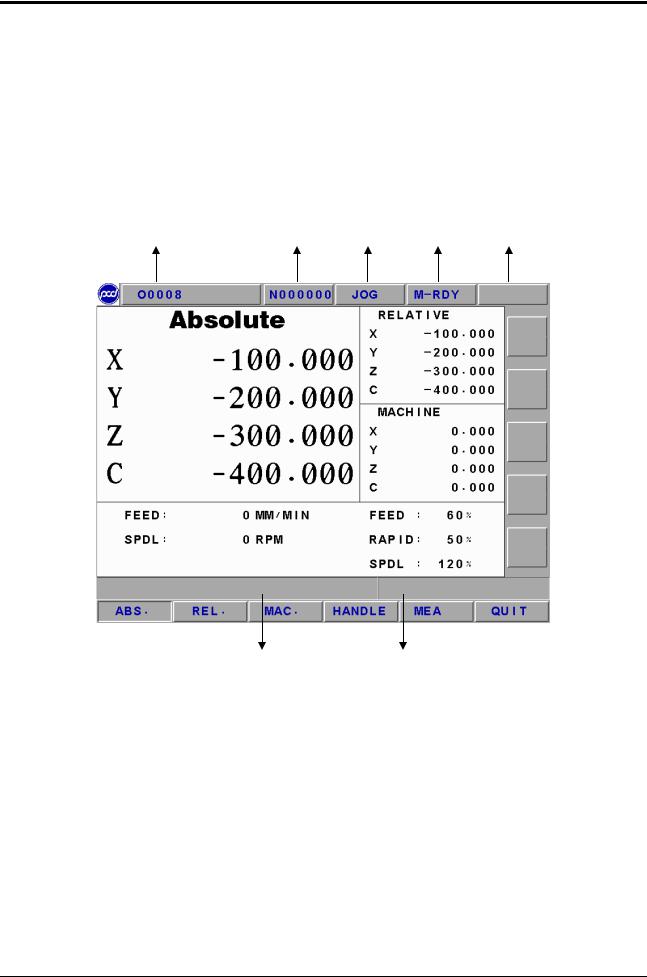
2.3.1Display Screen Layout
1 |
2 |
3 |
4 |
5 |
6 |
7 |
1 present designate file name
2 present single block that is executed by controller 3 CNC mode signal
4 machine condition signal
5 wrong alarm/warning message
6 simply message hint area
7 entry area
14 |
LNC Technology Co., Ltd. |
 LNC-M520i
CNC Operation
2.3.2Function Group Figure
Figure Example |
Real Example |
Indication |
|
|
|
|
|
|
|
|
|
Function group keys on MDI Panel.
Main function keys at button of LCD.
Sub function keys at right of LCD.
LNC Technology Co., Ltd. |
15 |

 LNC-M520i
CNC Operation
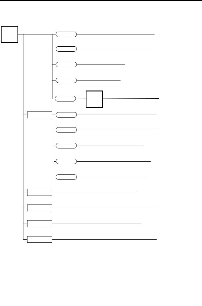
z POS Function Key Tree Figure
|
|
|
|
|
|
|
|
|
|
|
|
|
|
|
|
|
|
|
|
|
|
|
|
|
|
|
|
|
|
|
|
|
|
|
|
|
|
|
|
|
|
|
|
|
|
|
|
|
|
|
|
|
|
|
|
|
|
|
|
|
|
|
|
|
|
|
|
|
|
|
|
|
|
|
|
|
|
|
|
|
|
|
|
|
|
|
|
|
|
|
|
|
|
|
|
|
|
|
|
|
|
|
|
|
|
|
|
|
|
|
|
|
|
|
|
|
|
|
|
|
|
|
|
|
|
|
|
|
|
|
|
|
|
|
|
|
|
|
|
|
|
|
|
|
|
|
|
|
|
|
|
|
|
|
|
|
|
|
|
|
|
|
|
|
|
|
|
|
|
|
|
|
|
|
|
|
|
|
|
|
|
|
|
|
|
|
|
|
|
|
|
|
|
|
|
|
|
|
|
|
|
|
|
|
|
|
|
|
|
|
|
|
|
|
|
|
|
|
|
|
|
|
|
|
|
|
|
|
|
|
|
|
|
|
|
|
|
|
|
|
|
|
|
|
|
|
|
|
|
|
|
|
|
|
|
|
|
|
|
|
|
|
|
|
|
|
|
|
|
|
|
|
|
|
|
|
|
|
|
|
|
|
|
|
|
|
|
|
|
|
|
|
|
|
|
|
|
|
|
|
|
|
|
|
|
|
|
|
|
|
|
|
|
|
|
|
|
|
|
|
|
|
|
|
|
|
|
|
|
|
|
|
|
|
|
|
|
|
|
|
|
|
|
|
|
|
|
|
|
|
|
|
|
|
|
|
|
|
|
|
|
|
|
|
|
|
|
|
|
|
|
|
|
|
|
|
|
|
|
|
|
|
|
|
|
|
|
|
|
|
|
|
|
|
|
|
|
|
|
|
|
|
|
|
|
|
|
|
|
|
|
|
|
|
|
|
|
|
|
|
|
|
|
|
|
|
|
|
|
|
|
|
|
|
|
|
|
|
|
|
|
|
|
|
|
|
|
|
|
|
|
|
|
|
|
|
|
|
|
|
|
|
|
|
|
|
|
|
|
|
|
|
|
|
|
|
|
|
|
|
|
|
|
|
|
|
|
|
|
|
|
|
|
|
|
|
|
|
|
|
|
|
|
|
|
|
|
|
|
|
|
|
|
|
|
|
|
|
|
|
|
|
|
|
|
|
|
|
|
|
|
|
|
|
|
|
|
|
|
|
|
|
|
|
|
|
|
|
|
|
|
|
|
|
|
|
|
|
|
16 |
|
|
|
|
|
|
|
|
|
|
|
|
|
|
|
|
LNC Technology Co., Ltd. |
||

 LNC-M520i
CNC Operation
z PROG Function Key Tree Figure
|
|
|
|
|
|
|
|
|
|
|
|
|
|
|
|
|
|
|
|
|
|
|
|
|
|
|
|
|
|
|
|
|
|
|
|
|
|
|
|
|
|
|
|
|
|
|
|
|
|
|
|
|
|
|
|
|
|
|
|
|
|
|
|
|
|
|
|
|
|
|
|
|
|
|
|
|
|
|
|
|
|
|
|
|
|
|
|
|
|
|
|
|
|
|
|
|
|
|
|
|
|
|
|
|
|
|
|
|
|
|
|
|
|
|
|
|
|
|
|
|
|
|
|
|
|
|
|
|
|
|
|
|
|
|
|
|
|
|
|
|
|
|
|
|
|
|
|
|
|
|
|
|
|
|
|
|
|
|
|
|
|
|
|
|
|
|
|
|
|
|
|
|
|
|
|
|
|
|
|
|
|
|
|
|
|
|
|
|
|
|
|
|
|
|
|
|
|
|
|
|
|
|
|
|
|
|
|
|
|
|
|
|
|
|
|
|
|
|
|
|
|
|
|
|
|
|
|
|
|
|
|
|
|
|
|
|
|
|
|
|
|
|
|
|
|
|
|
|
|
|
|
|
|
|
|
|
|
|
|
|
|
|
|
|
|
|
|
|
|
|
|
|
|
|
|
|
|
|
|
|
|
|
|
|
|
|
|
|
|
|
|
|
|
|
|
|
|
|
|
|
|
|
|
|
|
|
|
|
|
|
|
|
|
|
|
|
|
|
|
|
|
|
|
|
|
|
|
|
|
|
|
|
|
|
|
|
|
|
|
|
|
|
|
|
|
|
|
|
|
|
|
|
|
|
|
|
|
|
|
|
|
|
|
|
|
|
|
|
|
|
|
|
|
|
|
|
|
|
|
|
|
|
|
|
|
|
|
|
|
|
|
|
|
|
|
|
|
|
|
|
|
|
|
|
|
|
|
|
|
|
|
|
|
|
|
|
|
|
|
|
|
|
|
|
|
|
|
|
|
|
|
|
|
|
|
|
|
|
|
|
|
|
|
|
|
|
|
|
|
|
|
|
|
|
|
|
|
|
|
|
|
|
|
|
|
|
|
|
|
|
|
|
|
|
|
|
|
|
|
LNC Technology Co., Ltd. |
17 |
||||||||||

 LNC-M520i
CNC Operation
z OFFSET Function Key Tree Figure
|
|
|
|
|
|
|
|
|
|
|
|
|
|
|
|
|
|
|
|
|
|
|
|
|
|
|
|
|
|
|
|
|
|
|
|
|
|
|
|
|
|
|
|
|
|
|
|
|
|
|
|
|
|
|
|
|
|
|
|
|
|
|
|
|
|
|
|
|
|
|
|
|
|
|
|
|
|
|
|
|
|
|
|
|
|
|
|
|
|
|
|
|
|
|
|
|
|
|
|
|
|
|
|
|
|
|
|
|
|
|
|
|
|
|
|
|
|
|
|
|
|
|
|
|
|
|
|
|
|
|
|
|
|
|
|
|
|
|
|
|
|
|
|
|
|
|
|
|
|
|
|
|
|
|
|
|
|
|
|
|
|
|
|
|
|
|
|
18 |
|
|
|
|
|
LNC Technology Co., Ltd. |
|

|
|
|
|
|
|
|
|
|
|
LNC-M520i |
|
|
|
|
|
|
|
|
|
|
CNC Operation |
z CAM Function Key Tree Figure |
|
|
||||||||
|
|
|
|
|
|
|
|
|
|
|
|
CAM |
|
|
|
|
|
ADD |
|
|
Add Geometry (2.7.4) |
|
|
|
|
|
|
|
||||
|
|
|
|
|
|
|
EDT |
|
Edit Geometry (2.7.4) |
|
|
|
|
|
|
|
|
|
|||
|
|
|
|
|
|
|
|
|||
|
|
|
|
|
|
|
DEL |
|
Delete Geometry (2.7.4) |
|
|
|
|
|
|
|
|
|
|||
|
|
|
|
|
|
|
TO CAP |
|
Switch to CAP (Conversational)(2.7.4) |
|
|
|
|
|
|
|
|
CAP |
|||
|
|
|
|
|
|
|
||||
|
|
|
|
|
|
|
|
|
|
|
|
|
|
|
|
|
|
|
|
|
|
|
|
|
|
PRJ. |
|
|
OPEN |
|
|
Open File (2.7.4) |
|
|
|
|
|
|
|
||||
|
|
|
|
|
|
|
NEW |
|
|
New Project (2.7.4) |
|
|
|
|
|
|
|
|
|||
|
|
|
|
|
|
|
DELETE |
|
Delete Project (2.7.4) |
|
|
|
|
|
|
|
|
|
|||
|
|
|
|
|
|
|
DXF IN |
|
Key-In AutoCAD.dxf File(2.7.4) |
|
|
|
|
|
|
|
|
|
|||
|
|
|
|
|
|
|
|
|
|
|
|
|
|
|
PARAM |
|
|
|
|
Tool Register (2.7.4) |
|
|
|
|
|
|
|
|
|
|||
|
|
|
|
|
|
|
|
|
|
|
|
|
|
|
V.DEF |
|
|
ZOOM |
|
Zoom-In Selected Graph Section (2.7.4) |
|
|
|
|
|
|
|
|
||||
|
|
|
|
|
|
|
HOME |
|
Auto-Decide Graph Size (2.7.4) |
|
|
|
|
|
|
|
|
|
|||
|
|
|
|
|
|
|
|
|
|
|
|
|
|
|
SAVE |
|
|
|
|
|
Save Project (2.7.4) |
|
|
|
|
|
|
|
|
|||
|
|
|
|
|
|
|
|
|
|
|
|
|
|
|
POST |
|
|
ROUGH |
|
Rough Working Program (2.7.4) |
|
|
|
|
|
|
|
|
||||
|
|
|
|
|
|
|
FINISH |
|
Fine Working Program (2.7.4) |
|
|
|
|
|
|
|
|
|
|||
|
|
|
|
|
|
|
|
|
|
|
|
|
|
|
CLOSE |
|
|
|
|
|
Close Project (2.7.4) |
|
|
|
|
|
|
|
|
|
||
Note: There is no actual CAP key on MDI. Here just indicate easy use.
LNC Technology Co., Ltd. |
19 |
 LNC-M520i
CNC Operation
z CAP Function Key Tree Figure
Note: There is no actual CAP key on MDI. Here just indicate easy use.
20 |
LNC Technology Co., Ltd. |

|
|
|
|
|
LNC-M520i |
|
|
|
|
|
CNC Operation |
z GRAPH Function Key Tree Figure |
|
||||
|
|
|
|
|
|
|
GRAP |
|
|
|
|
|
|
GRAPH |
|
Drawing Working Path (2.9.2) |
|
|
H |
|
|
||
|
|
|
|
|
|
|
|
|
|
|
|
|
SET |
|
|
Setting Drawing Windows (2.9.3) |
|
|
|
LNC Technology Co., Ltd. |
21 |

 LNC-M520i
CNC Operation
z DGNOS Function Key Tree Figure
DGN |
IOCSA |
I |
|
O |
|
|
C |
|
|
S |
|
|
A |
|
MLC2 |
LAD |
|
|
CNT |
|
|
REG |
|
|
DRG |
|
|
TMR |
|
SYSTEM |
GBL |
|
|
H.D |
|
RST |
CLR TMR |
|
|
CLR CNT |
|
|
INI CNT |
|
|
MAX CNT |
|
SYSUPD |
|
|
CIRCUL |
START |
|
ALARM |
ADD |
|
ADD 1 |
||
ADD 10 |
||
ADD 100 |
||
OS |
|
WARN |
|
|
HISMSG |
|
|
LOGHST |
|
PGDN |
|
Display System Alarm (2.10.1)
Display System Warning (2.10.1)
Display System Version and Program Debugging Message (2.10.1)
Display System Alarm/Warning Record (2.10.1)
Display I Bit (2.10.2)
Display O Bit (2.10.2)
Display C Bit (2.10.2)
Display S Bit (2.10.2)
Display A Bit (2.10.2)
Display LADDER Diagram (2.10.3)
Display Counter Value (2.10.3)
Display R Register (2.10.3)
Display D Register (2.10.3)
Display Timer Value (2.10.3)
Display System Maintenance Variable (2.10.4)
Display Hardware Diagnosis Condition (2.10.4)
Clear Running Time (2.10.5)
Clear Working Part (2.10.5)
Setting Start Working Part(2.10.5)
Setting Target Working Part (2.10.5)
Enter into System Upgrade Page (2.10.6)
Start Canned Cycle (2.10.7) Setting Error to +/- (2.10.7)
Setting Error to +/- 1 Percent (2.10.7) Setting Error to +/- 10 Percent (2.10.7) Setting Error to +/- 100 Percent (2.10.7)
22 |
LNC Technology Co., Ltd. |

 LNC-M520i
CNC Operation
z SOFTPL Function Key Tree Figure
SOFTP |
|
|
|
M LOCK |
|
L |
|
|
|
|
|
|
|
|
 DRY RUN
 OP SKIP
 OP STOP
MST SKIP
MPG DRY
Z IGN
Enable Machine Lock (2.11)
Enable Dry Run (2.11)
Enable Option Skip (2.11)
Enable Option Stop (2.11)
Enable MST Ignore (2.11)
Enable MPG Dry Run (2.11)
Enable Z Axis Ignore (2.11)
LNC Technology Co., Ltd. |
23 |

 LNC-M520i
CNC Operation
z PARAM Function Key Tree Figure Machine Maker
24 |
LNC Technology Co., Ltd. |
 Loading...