


LNC-Lathe

LNC Technology Co., Ltd. 1
Leading Numerical Controller
LNC-Lathe Series
P
P
r
r
o
o
g
g
r
r
a
a
m
m
m
m
i
i
n
n
g
g
M
M
a
a
n
n
u
u
a
a
l
l
2007/12 Ver:V04.00.003
LNC Technology Co., Ltd.


LNC Lathe
Table of Content
LNC Technology Co., Ltd. I
Table of Content
1 G-CODE FUNCTION TABLE....................................................................1
2 GENERAL M-CODE FUNCTION TABLE.................................................5
3 SYNTAX OF G CODE...............................................................................7
G00: Positioning in rapid....................................................................................................................7
G01: Linear interpolation....................................................................................................................9
G02, G03: Circular interpolation (cw./ccw.).......................................................................................10
Direct pattern making.......................................................................................................................12
G04: Dwell.......................................................................................................................................23
G09: Exact stop................................................................................................................................24
G10: Data setting.............................................................................................................................25
G20, G21: Inch \ mm input................................................................................................................27
G22, G23: Stored stroke check ON / OFF.........................................................................................28
G27: Reference position return check...............................................................................................29
G28: 1st reference position return.....................................................................................................30
G29: From 1st reference position return............................................................................................31
G30: 2nd,3rd,4th, reference position return.......................................................................................32
G31: Skip function............................................................................................................................34
G33: Thread cutting..........................................................................................................................36
G34: Variable Thread Pith Threading................................................................................................38
Continuous Threading......................................................................................................................40
G40, G41, G42: Tool nose radius compensation...............................................................................45
G53: Machine coordinate system......................................................................................................47
G54 ~ G59: Selection of work coordinate system..............................................................................49
G61, G64: Exact stop mode / Cutting mode......................................................................................51
G65: User macro simple call.............................................................................................................52
G66: User macro modal call.............................................................................................................54
G67: User macro modal call cancel..................................................................................................55
G68: Mirror image for double turrets ON...........................................................................................56
G69: Mirror image for double turrets OFF.........................................................................................56
G70: Finishing Cycle........................................................................................................................58

LNC Lathe
G-Code Function Table
II LNC Technology Co., Ltd.
G71: Stock removal in turning...........................................................................................................59
G72: Stock removal in facing............................................................................................................61
G73: Pattern repeating.....................................................................................................................63
G74: End face peck drilling cycle (Z axis).........................................................................................65
G75: Outer diameter / Internal diameter drilling cycle (X axis)...........................................................66
G76: Multiple thread cutting cycle.....................................................................................................67
G77: Outer diameter/internal diameter cutting cycle..........................................................................69
G78: Taper thread cutting cycle........................................................................................................70
G79: End face turning cycle..............................................................................................................75
G80: Canned cycle for drilling cancel................................................................................................76
G83: Face drilling cycle....................................................................................................................77
G84: Face tapping cycle...................................................................................................................81
G85: Face boring cycle.....................................................................................................................83
G87: Side drilling cycle (X axis)........................................................................................................85
G88: Side tapping cycle (X axis).......................................................................................................89
G89: Side boring cycle (X axis).........................................................................................................92
G187: Side drilling cycle (Y axis)......................................................................................................94
G188: Side tapping cycle (Y axis).....................................................................................................98
G189: Side boring cycle (Y axis).....................................................................................................100
G90, G91: Absolute / Incremental programming..............................................................................102
G92: Coordinate system setting or max. spindle speed setting........................................................103
G94, G95: Feed per minute (mm/min), Feed per revolution (mm/rev)..............................................104
G96, G97: Constant surface speed control ON / OFF.....................................................................105
G98, G99: Intial point return / R point return....................................................................................106
4 AUXILIARY FUNCTION (M CODE)......................................................107
5 MACRO.................................................................................................112
5.1 Macro program introduction.....................................................................................................112
5.2 User macro call.......................................................................................................................113
5.3 Difference between macro program call (G65) and general subprogram call (M98)..................118
5.4 MACRO function list................................................................................................................119
5.5 Variable...................................................................................................................................120
5.6 Mathematics command............................................................................................................130
5.7 Logic command.......................................................................................................................131

LNC Lathe
Table of Content
LNC Technology Co., Ltd. III
5.8 Compare command.................................................................................................................132
5.9 Procedures control command..................................................................................................133
5.10 Function..................................................................................................................................134
5.11 Note........................................................................................................................................136


LNC Lathe
G-Code Function Table
LNC Technology Co., Ltd. 1
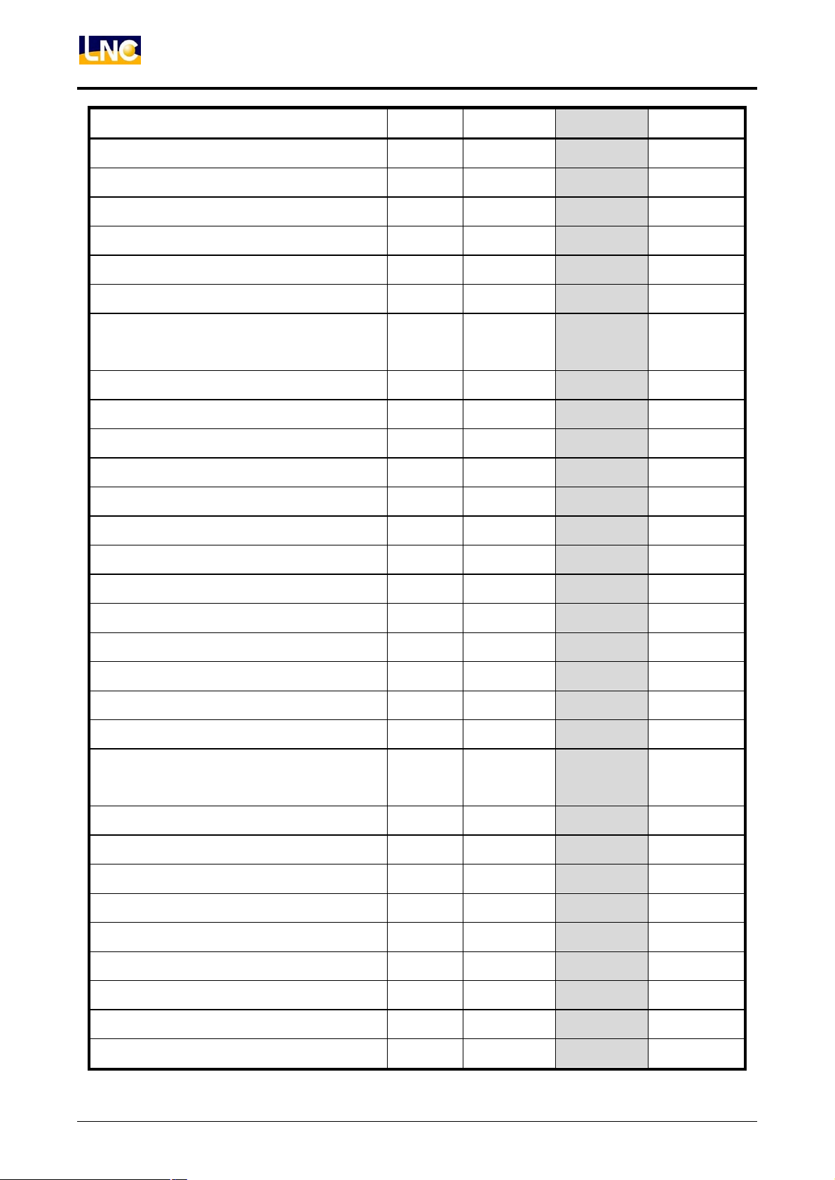
1 G-Code Function Table
Function Group TYPE A TYPE B TYPE C
Positioning in rapid 01 G00 G00 G00
Linear interpolation 01 G01 G01 G01
Circular interpolation (cw.) 01 G02 G02 G02
Circular interpolation (ccw.) 01 G03 G03 G03
Dwell 00 G04 G04 G04
Exact stop 00 G09 G09 G09
Data setting 00 G10 G10 G10
ARC Plane Setting 02 G17~19 G17~19 G17~19
input in inch 06 G20 G20 G70
input in mm 06 G21 G21 G71
Stored stroke check ON 09 G22 G22 G22
Stored stroke check OFF 09 G23 G23 G23
Reference position return check 00 G27 G27 G27
1st reference position return 00 G28,G29 G28,G29 G28,G29
2nd,3rd,4th, reference position return 00 G30 G30 G30
Skip function 00 G31 G31 G31
Thread cutting 01 G32 G33 G33
Variable Thread Pith Threading 01 G34 G34 G34
Tool nose radius compensation Cancel 07 G40 G40 G40
Tool nose radius compensation Left 07 G41 G41 G41
Tool nose radius compensation Right 07 G42 G42 G42
Machine coordinate system 00 G53 G53 G53
Selection of work coordinate system 14 G54 ~G59 G54 ~ G59
G54 ~ G59
Exact stop mode 15 G61 G61 G61
Cutting mode 15 G64 G64 G64
User macro simple call 00 G65 G65 G65
User macro modal call 12 G66 G66 G66
User macro modal call cancel 12 G67 G67 G67
Mirror image for double turrets ON 16 G68 G68 G68
LNC Lathe
G-Code Function Table
2 LNC Technology Co., Ltd.
Function Group TYPE A TYPE B TYPE C
Mirror image for double turrets OFF 16 G69 G69 G69
Finishing Cycle 00 G70 G70 G72
Stock removal in turning 00 G71 G71 G73
Stock removal in facing 00 G72 G72 G74
Pattern repeating 00 G73 G73 G75
End face peck drilling cycle (Z axis) 00 G74 G74 G76
Outer diameter / Internal diameter drilling cycle
(X axis)
00 G75 G75 G77
Multiple thread cutting cycle 00 G76 G76 G78
Outer diameter/internal diameter cutting cycle 01 G90 G77 G20
Taper thread cutting cycle 01 G92 G78 G21
End face turning cycle 01 G94 G79 G24
Canned cycle for drilling cancel 10 G80 G80 G80
Face drilling cycle 10 G83 G83 G83
Face tapping cycle 10 G84 G84 G84
Face boring cycle 10 G85 G85 G85
Side drilling cycle (X axis) 10 G87 G87 G87
Side tapping cycle (X axis) 10 G88 G88 G88
Side boring cycle (X axis) 10 G89 G89 G89
Absolute programming 03 - G90 G90
Incremental programming 03 - G91 G91
Coordinate system setting or max. spindle
speed setting
00 G50 G92 G92
Feed per minute (mm/min) 05 G98 G94 G94
Feed per revolution (mm/rev) 05 G99 G95 G95
Constant surface speed control ON 02 G96 G96 G96
Constant surface speed control OFF 02 G97 G97 G97
Intial point return 11 - G98 G98
R point return 11 - G99 G99
Side drilling cycle (Y axis) 10 187 187 187
Side tapping cycle (Y axis) 10 188 188 188
Side boring cycle (Y axis) 10 189 189 189

LNC Lathe
G-Code Function Table
LNC Technology Co., Ltd. 3
Function Group TYPE A TYPE B TYPE C
(Note)The TYPE is A, B or C to decide on the Pr153, default is TYPE B.


LNC Lathe
General M-Code Function Table
LNC Technology Co., Ltd. 5
2 General M-Code Function Table
M Code Function Remark
M00 Program stop CNC
M01 Optional stop CNC
M02 End of program CNC
M03 Spindle CW
M04 Spindle CCW
M05 Spindle stop
Txx Auto tool change
xx:Tool no.
M08 Coolant ON
M09 Coolant OFF
M10 Chuck clamp
M11 Chuck unclamp
M30 Program rewind CNC
M98 Calling of subprogram CNC
M99 End of subprogram CNC


LNC Lathe
Syntax of G code
LNC Technology Co., Ltd. 7
3 Syntax of G code
G00: Positioning in rapid
Format:
G00 X___ Y___ Z___ C___;
Argument:
X__ Y__ Z__
C__
:
For G90, the coordinate of an end point in absolute command.
For G91, the coordinate of an end point in Incremental command.
Action:
The function of G00 command is to make the tool move to the position of the specified coordinate
rapidly.
When using G00, the speed of moving is not descided by the format of F__, but by setting values of
parameter 1000 ~ 1003. Meanwhile, the rapid traverse adjustment knob can be used to adjust the
percentage of speed. (F0, 25%, 50%, 100%)
Illustration:
Note:
Regarding G00 movement command, the movement of each servo axis is independent. The
movement speed of each axis is specified by parameters respectively. Operators should be
especially careful lest the tool may collide with the workpiece.
X
Y
Z
Start
Target
Tool path

LNC Lathe
Syntax of G code
8 LNC Technology Co., Ltd.
Methods of determing G00 simultaneously interpolated feed rate
G00 command or commands with same
function under MEM, MDI modes
G00, G53 command of PMC axis function
None dry run
mechanism
Moving speed of each
axis does not exceed
respectively set G00 speed (Remark 1)
Moving speed of each axis does not
exceed respectively set G00 speed
Dry run mechanism
paremeter 0083 is 0
Moving speed of each axis does not exceed
respectively set JOG speed (Remark 2)
C23 is OFF: Moving speed of each axis
does not exceed respectively set JOG
speed
C23 is ON: Moving speed of each axis
does not exceed respectively set G00
speed
Dry run mechanism
paremeter 0083 is 1
Moving speed of each axis does not exceed
respectively set G00 speed
Moving speed of each axis does not
exceed respectively set G00 speed
Remark 1 Under this condition, Override depends on rapid traverse percentage.
Remark 2 Under this condition, Override depends on cutting feed percentage.

LNC Lathe
Syntax of G code
LNC Technology Co., Ltd. 9
G01: Linear interpolation
Format:
G01 X(U)___ Z(W)___ F___;
Argument:
X___, Z___ :
For G90, the coordinate of an end point in absolute command.
For G91, the coordinate of an end point in Incremental command.
U___, W___ :
For G90/G91, the coordinate of an end point in Incremental
command.
F___ :
Feedrate.
Action:
G01 depends on the interpolation feed rate specified by F code, starts from current tool position, to
cut in a linear path to the end. Axes which are not specified do not move. Actual cutting feed can be
adjusted by the continuous feed rate adjustment knob at any time (0%-150%).
Max interpolation feed rate of G01 is specified by system parameter 1004. Acc/Dec time of G01 is
specified by system parameter 0014.
Illustration:
G90 G92 X100. Z100.;
G01 X10. Z10. F50;
(100,100)
(10,10)
G91 G92 X100. Z100.;
G01 X10. Z10. F50;
(100,100)
(110,110)
G92 X100. Z100.;
G01 U10. W10. F50;
(100,100)
(110,110)
G90 G92 X100. Z100.;
G01 X10. F50;
(100,100)
(10,100)

LNC Lathe
Syntax of G code
10 LNC Technology Co., Ltd.
G02, G03: Circular interpolation (cw./ccw.)
Format:
;F__
R__
I__K__
Z(W)__X(U)__
G03
G02
Argument:
X___, Z___ :
For G90, the coordinate of an end point in absolute command.
For G91, the coordinate of an end point in Incremental command.
U___, W___ :
For G90/G91, the coordinate of an end point in Incremental
command.
R___ :
Arc radius. (R>0, Arc<=180°. R<0. Arc>180°)
I___ :
Xp axis distance from start point to the center of an arc. Xp is a
component in X direction.
K___ :
Zp axis distance from start point to the center of an arc. Zp is a
component in Z direction.
F___ :
Feedrate.
Action:
Pay attention to current tool position. The end point and the center of circle should be in the same
circle. If not, the controller emits an error signal INT 132. When R___, I___, and K___ of the
program are all written-in, system will depends only on the setting of R___.
System parameter 132 (XRC) defines if X (U) position is radius-specified or diameter-specified.
Radius-specified (XRC=1) and diameter-specified (XRC=0) differ in 2 times of the actual movement
amount of X axis. E.g. The movement amount of radius-specified U-10 is equal to
diameter-specified U-20.
G
0
3
Centre
K
+X
G
0
3
I
+Z
Starting point
G
0
2
End point
Centre
+X
+Z

LNC Lathe
Syntax of G code
LNC Technology Co., Ltd. 11
Illustration:
The following 4 figures have the same cutting path of a clockwise cutting of a 1/4 circle, and the
radius is 5.
(In radius programming)
G91 G92 X100. Z100.;
G02 X-5. Z5. I-5. K0. F50;
(In radius programming)
G90 G92 X100. Z100.;
G02 X95. Z105. I-5. K0. F50;
(In diameter programming)
G91 G92 X100. Z100.;
G02 X-10. Z5. I-5. K0. F50;
(In diameter programming)
G90 G92 X100. Z100.;
G02 X90. Z105. I-5. K0. F50;
(100,100)
(90,100)
(100,100)
(90,100)
(100,100)
(90,100)
(100,100)
(90,100)

LNC Lathe
Syntax of G code
12 LNC Technology Co., Ltd.
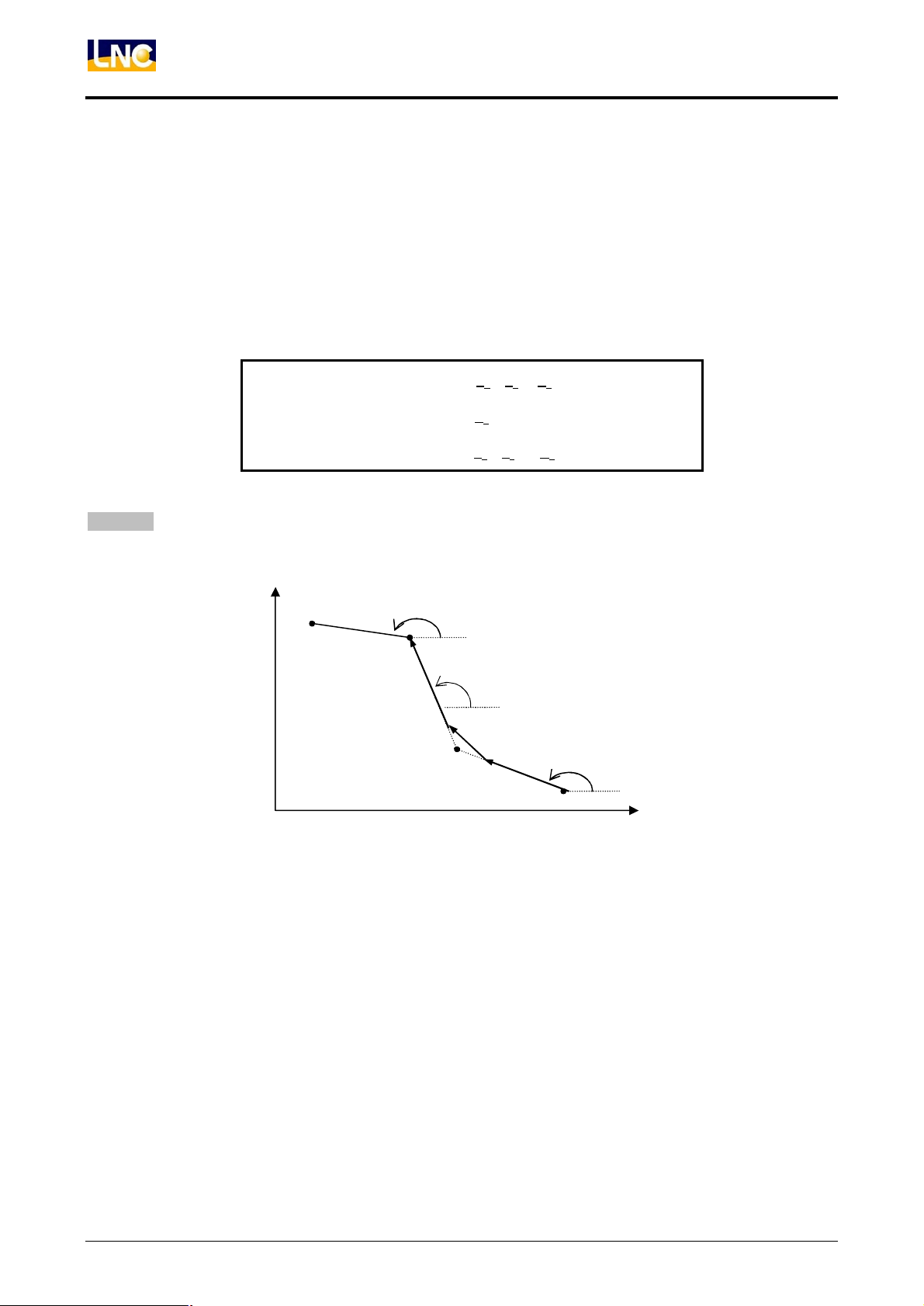
Direct pattern making
In order to make the manufacturing of workpieces easier, the controller provides functions of making corner
chamfering (,C_), corner rounding (,R_) and angle of straight line (A_).
1. Chamfering “,C_”
Continuous 2 blocks of command. In the 1
st
block, C_ sets up chamfer length between the 2 blocks. It is
applicable also when the previous and next blocks are circular commands.
Format:
Z__;X__
G03
G02
G01
C__; , Z__X__
G03
G02
G01
Example:
G00 X20.0 Z40.0
G01 X80.0,C10.0 F100.0
G01 Z10.0
End point of
1st block
,C_
X
Z
C10
Z
X
(20,40)
(80,40)
(80,10)

LNC Lathe
Syntax of G code
LNC Technology Co., Ltd. 13
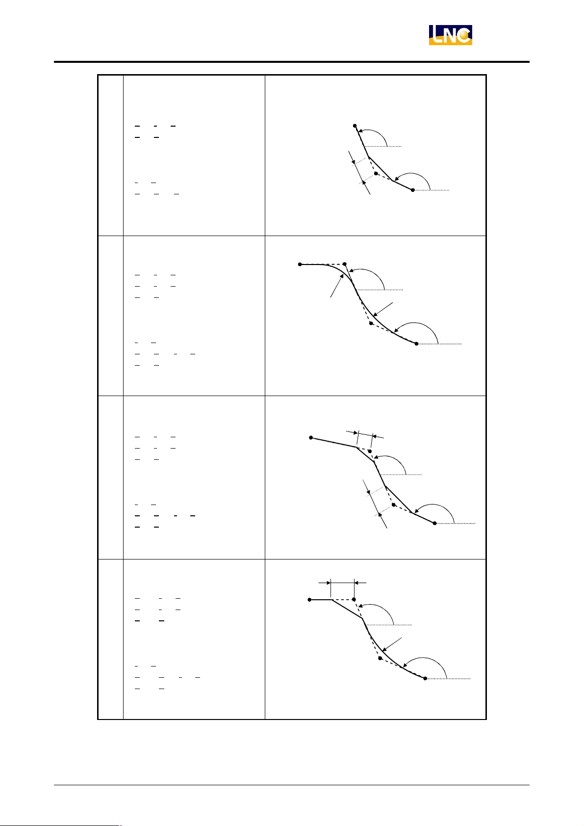
2. Corner Rounding “,R_”
Continuous 2 blocks of command. In the 1
st
block,,R_ sets up the radius of the rounding corner linking the
2 blocks. It is applicable also when the previous and next blocks are circular commands.
Format:
Z__;X__
G03
G02
G01
R__; , Z__X__
G03
G02
G01
Example:
G00 X20.0 Z0.0
G02 X20.0 R10.0,R3.0 F100.0
G01 Z30.0
Z
X
,R_
X
(20,0)
(20,20)
(20,30)
R10
Z

LNC Lathe
Syntax of G code
14 LNC Technology Co., Ltd.
3. Angle of Straight Line ”A_”
When applying linear interpolation command G01, only the positions of X_ or Z_ and the angle of the line
A_ can be specified. The actual position of the corresponding end point will be calculated by the controller.
It is especially convenient when the manufacturing drawing provides only coordinates of X or Z directions
and angles.
Format:
A__;
Z__
X__
G01
Wherein A_ angle is calculated from the horizontal direction (Z axis). A positive value of A represents
a counterclockwise direction, and vice versa.
Example:
G00 X10.0 Z10.0
G01 X20.0 A27.0 F100.0
Z
X
(X, Z)
A-
Z
X
(X, Z)
A+
X
(10,10)
(20, ??)
27°
Z

LNC Lathe
Syntax of G code
LNC Technology Co., Ltd. 15
4. Geometric input function
In a manufacturing drawing, it is often that angles are provided, but not correct cutting positions; or that
only the size of corner or round corner is provided when making a corner. Therefore the calculation of the
coordinates of the intermediate point can be inconvenient when transforming the data to linear and
circular cutting command while compiling a manufacturing program. This function makes compiling
programs more easily, and help avoid calculation errors.
l Type 1
Intersection point of 1
st
and 2
nd
blocks is unknown
Angles of 1
st
and 2
nd
blocks are known
End point coordinates are known
Format:
N01 G01 Aa
1
N02 G01 Xx
3
Zz
3
Aa
2
a
1
a
2
?
(x3, z3)
Z
X
N01
N02
(x1, z1)

LNC Lathe
Syntax of G code
16 LNC Technology Co., Ltd.
Example:
G00 X0.0 Z0.0
G01 A30.0
G01 X10.0 Z30.0 A-45.0
l Type 2
Intersection point of 1
st
and 2
nd
blocks is unknown
Angles of 1
st
and 2
nd
blocks are known
End point coordinates are known
Corner of 1
st
and 2
nd
blocks is chamfer or fillet
N01 G01 Aa1,Cc1 (,Rr1)
N02 G01 Xx3 Zz3 Aa2
Format:
-45°
(10,30)
X
30°
Coordinates of intermediate point are unknown
Z
C1 or r1
a
2
a
1
?
(z
3
,z
3
)
N01
N02
(z
1
,z
1
)
Z
X

LNC Lathe
Syntax of G code
LNC Technology Co., Ltd. 17
l Type 3
Either X_ or Z_ of the intersection point of 1
st
and 2
nd
blocks is known
Intersection point of 2
nd
and 3
rd
blocks is unknown
Coordinates of end point of 3
rd
block are known
Angles of 1
st
, 2
nd
and 3
rd
blocks are known
N01 G01 Xx2(Zz2) Aa1
N02 G01 Aa2
N03 G01 Xx4 Zz4 Aa3
Format:
Z
X
a
2
a
1
?
(z
2
,z
2
)
N01
N03
a
3
(z
4
,z
4
)
N02
LNC Lathe
Syntax of G code
18 LNC Technology Co., Ltd.
l Tyep 4
Intersection point of 1
st
and 2
nd
blocks is known
Intersection point of 2
nd
and 3
rd
blocks is unknown
Coordinates of end point of 3
rd
block is known
Angles of 1
st
, 2
nd
and 3
rd
blocks are known
Corner of 1
st
and 2
nd
blocks is chamfer or fillet
N01 G01 Xx
2
(Zz
2
) Aa
1
N02 G01 Aa
2
N03 G01 Xx
4
Zz
4
Aa
3
Format:
Z
X
C
1
or r1
a
2
a
1
?
(z
2
,z
2
)
N01
N03
a
3
(z
4
,z
4
)
N02

LNC Lathe
Syntax of G code
LNC Technology Co., Ltd. 19
l Type 5
Intersection point of 1
st
and 2
nd
blocks is unknown
Intersection point of 2
nd
and 3
rd
blocks is known
Coordinates of end point of 3
rd
block are known
Angles of 1
st
and 2
nd
blocks are known
Corner of 1
st
and 2
nd
blocks is chamfer or fillet
Corner of 2
nd
and 3
rd
blocks is chamfer or fillet
N01 G01 Xx
2
Zz
2
,Cc
1
(,Rc
1
)
N02 G01 Aa
2
N03 G01 Xx
3
Zz
3
Aa
1
Format:
Note:
1. The following G codes can not be in the same block with geometric input commands, or be used to
input pattern size of continuous shapes.
a. G codes of Group 00 (excluding G04)
b. G02, G03, G90, G92, G94 of Group 01
2. Only be effective under MEM Mode
3. Fillet command can not be used in thread-cutting blocks.
4. When applying G01 X_ A_, if angle value is 0∘±1, 180∘±1, then the command is ineffective.
5. When applying G01 Z_ A_, if angle value is 90∘±1, 270∘±1, then the command is ineffective.
6. If the angle between 2 lines is within +1∘, chamfering and filleting will be ignored.
Z
C1 or r1
a
2
a
1
(z
3
,z
3
)
?
N01
N03
(z
4
,z
4
)
N02
C2 or r2
X

LNC Lathe
Syntax of G code
20 LNC Technology Co., Ltd.
Table of usages of geometric commands
Command Illustration
1
X
2
(Z
2
_) A
2
A
1
X
3
Z
3
A
2
3
X
2
Z
2
,R
1
X
3
Z
3
or
A
1
,R
1
X
3
Z
3
A
2
(X
1,
Z
1
)
A
(X
2,
Z
2
)
(X
2,
Z
2
)
(X
1,
Z
1
)
A
2
(X
3,
Z
3
)
A
1
(X
2
,
Z
2
)
(X
1,
Z
1
)
A
1
(X
3,
Z
3
)
A
2
R
LNC Lathe
Syntax of G code
LNC Technology Co., Ltd. 21
4
X
2
Z
2
,C
1
X
3
Z
3
or
A
1
,C
1
X
3
Z
3
A
2
5
X
2
Z
2
,R
1
X
3
Z
3
,R
2
X
4
Z
4
or
A
1
,R
1
X
3
Z
3
A
2
,R
2
X
4
Z
4
6
X
2
Z
2
,C
1
X
3
Z
3
,C
2
X
4
Z
4
or
A
1
,C
1
X
3
Z
3
A
2
,C
2
X
4
Z
4
7
X
2
Z
2
,R
1
X
3
Z
3
,C
2
X
4
Z
4
or
A
1
,R
1
X
3
Z
3
A
2
,C
2
X
4
Z
4
(X
2,
Z
2
)
(X
1,
Z
1
)
A
1
(X
3,
Z
3
)
A
2
C
1
(X
2,
Z
2
)
(X
1,
Z
1
)
A
1
(X
3,
Z
3
)
A
2
R
1
(X
4,
Z
4
)
R
2
(X
2,
Z
2
)
(X
1,
Z
1
)
A
1
(X
3,
Z
3
)
A
2
C
1
C
2
(X
4,
Z
4
)
(X
2,
Z
2
)
(X
1,
Z
1
)
A
1
(X
3,
Z
3
)
A
2
R
1
(X
4,
Z
4
)
C
2

LNC Lathe
Syntax of G code
22 LNC Technology Co., Ltd.
8
X
2
Z
2
,C
1
X
3
Z
3
,R
2
X
4
Z
4
or
A
1
,C
1
X
3
Z
3
A
2
,R
2
X
4
Z
4
(X
2,
Z
2
)
(X
1,
Z
1
)
A
1
(X
3,
Z
3
)
A
C
1
R
2
(X
4,
Z
4
)

LNC Lathe
Syntax of G code
LNC Technology Co., Ltd. 23
G04: Dwell
Format:
G04 X___;
G04 P___;
Argument:
X___ :
Specify a time. Unit: sec. Range: 0.001 ~ 99999.999.
P___ :
Specify a time. Unit: ms. No decimal poiint. Range: 1 ~ 99999999.
Action:
Dwell action; set up dwell time after G04; when the time is over, next block will be executed
automatically.
Example:
G04 X100.;------------------------------------------------------- 100 sec
G04 P100;---------------------------------------------------------0.1 sec
G04;------------------------------------------------------ Exact stop (G09)
LNC Lathe
Syntax of G code
24 LNC Technology Co., Ltd.
G09: Exact stop
Format:
;
__03G
__02G
__01G
09G
Argument:
G09 is a command used along with the exact stop of cutting. When using G09, system checks
positioning degrees after executing every positioning command. After making sure statuses of
positioning comply with settings, system continues executing next block. Therefore, if cutting
positioning exists between blocks, there might be a little interruption due to the demanding of the
precision of positioning point. Speed is sacrificed for a higher shape precision. The degree of
precision is specified by parameters 0006 ~ 0009. The function of G09 only takes effect within its
block.
Example:
G91 G09 G01 Y100. F200.;-------------------------------------------------------------------------------------- (1)
G01 X100.;----------------------------------------------------------------------------------------------------------- (2)
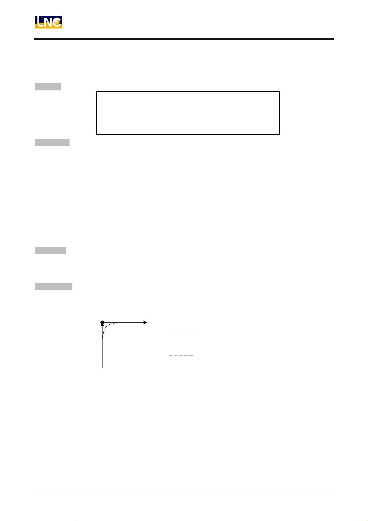
Illustration:
Tool path in non-exact stop
Tool path in G09
(1)
(2)
 Loading...