

Page 1

R6000-Robot
Operator’s Manual
Leading Numerical Controller
2012/03 ver.:V01.00 (4408990058)
LNC Technology Co., Ltd.
1
LNC Technology Co., Ltd.
Page 2

Page 3

LNC-R6000
Table of content
Table of content
Table of content ................................................................................................ I
1 Operation Interface ................................................................................... 1
2 Home .......................................................................................................... 2
2.1 How to return home ............................................................................................................................ 2
3 MANUAL..................................................................................................... 3
3.1 MANUAL ............................................................................................................................................. 3
3.1.1 Output ........................................................................................................................................ 3
3.1.2 Manual continuous axis move mode ......................................................................................... 4
3.1.3 JOG ........................................................................................................................................... 5
3.1.4 Return to standby ...................................................................................................................... 5
3.2 IO status .............................................................................................................................................. 6
3.3 Standby tuning .................................................................................................................................... 7
4 Auto ............................................................................................................ 8
4.1 Monitor ................................................................................................................................................ 8
4.1.1 Button Description ..................................................................................................................... 9
4.1.2 Modify program under auto running. ......................................................................................... 9
4.2 IO status ............................................................................................................................................ 10
4.3 Stack setting ...................................................................................................................................... 10
4.4 Sample/reject .................................................................................................................................... 10
4.5 Cycle monitor ..................................................................................................................................... 11
4.5.1 Conveyor setting ..................................................................................................................... 12
4.5.2 Process machine setting ......................................................................................................... 12
5 Teach ........................................................................................................ 13
5.1 Edit .................................................................................................................................................... 13
5.1.1 Function key ............................................................................................................................ 13
5.1.2 Program command detail ........................................................................................................ 14
5.1.3 Axis .......................................................................................................................................... 14
5.1.4 Speed ...................................................................................................................................... 16
5.1.5 Delay ....................................................................................................................................... 17
5.1.6 Robot I/O ................................................................................................................................. 18
5.1.7 Injection molding machine I/O ................................................................................................. 19
5.1.8 Vacuum/gripper I/O.................................................................................................................. 21
I
LNC Technology Co., Ltd.
Page 4

LNC-R6000
Table of content
5.1.9 Peripheral device I/O ............................................................................................................... 22
5.1.10 Call stack .............................................................................................................................. 24
5.1.11 Call MACRO ......................................................................................................................... 25
5.1.12 Stop 26
5.1.13 Calculating ........................................................................................................................... 27
5.1.14 Jump 28
5.1.15 Loop 31
5.2 IO Status ........................................................................................................................................... 31
5.3 Stack setting ...................................................................................................................................... 32
5.4 Sample/reject .................................................................................................................................... 34
5.4.1 Sample check .......................................................................................................................... 34
5.4.2 Reject give up .......................................................................................................................... 35
5.5 File manage ...................................................................................................................................... 36
5.5.1 Open a new mold file ............................................................................................................... 37
5.5.2 Read old mold file .................................................................................................................... 38
5.5.3 Copy current mold file ............................................................................................................. 39
5.5.4 Delete mold file ........................................................................................................................ 40
5.5.5 Upload/download mold file via USB ........................................................................................ 40
5.6 Safe area .......................................................................................................................................... 41
5.6.1 No go area setting for 3 axes .................................................................................................. 41
5.6.2 No go area setting for 5 axes .................................................................................................. 44
5.7 @Variables ........................................................................................................................................ 46
5.8 MACRO ............................................................................................................................................. 47
6 Parameter ................................................................................................. 48
6.1 General parameter ............................................................................................................................ 48
6.2 Language .......................................................................................................................................... 49
6.3 Common parameter .......................................................................................................................... 50
6.4 Machine parameter ........................................................................................................................... 51
6.5 Maintain ............................................................................................................................................ 52
6.5.1 Maintain setting ....................................................................................................................... 52
6.5.2 Maintain status ........................................................................................................................ 52
6.5.3 Maintain history ....................................................................................................................... 53
6.6 Network ............................................................................................................................................. 54
7 System ..................................................................................................... 55
7.1 About ................................................................................................................................................. 55
7.2 System info ....................................................................................................................................... 56
II
LNC Technology Co., Ltd.
Page 5

LNC-R6000
Table of content
7.3 Ladder ............................................................................................................................................... 57
7.4 R bit ................................................................................................................................................... 58
7.5 System parameter............................................................................................................................. 58
7.6 I/O Map ............................................................................................................................................. 59
7.6.1 DI Map ..................................................................................................................................... 59
7.6.2 DO Map ................................................................................................................................... 60
7.6.3 DI Map、DO Map setting ........................................................................................................ 60
7.7 Backup .............................................................................................................................................. 62
7.7.1 Parameter backup ................................................................................................................... 62
7.7.2 Parameter restore ................................................................................................................... 64
7.8 Upgrade ............................................................................................................................................ 68
7.9 Operator authority ............................................................................................................................. 71
7.10 I/O ..................................................................................................................................................... 72
7.11 Change password ............................................................................................................................. 73
7.12 Monitor tuning ................................................................................................................................... 75
8 Alarm record ............................................................................................ 77
8.1 Alarm ................................................................................................................................................. 77
8.2 Warning ............................................................................................................................................. 78
8.3 Alarm/warning history ....................................................................................................................... 79
8.4 Operation history .............................................................................................................................. 80
9 Switch users ............................................................................................ 81
10 Parameter ................................................................................................. 82
10.1 General parameter ............................................................................................................................ 82
10.2 Common parameterMutual parameter .......................................................................................... 83
10.3 Common parameterAxis parameter .............................................................................................. 86
11 Troubleshooting ...................................................................................... 88
11.1 Alarm troubleshooting ....................................................................................................................... 88
11.2 Warning troubleshooting ................................................................................................................... 94
12 Q&A .......................................................................................................... 95
12.1 How to write note of movement command of mold document ......................................................... 95
12.1.1 Add one line note for movement command ......................................................................... 95
12.1.2 Modify note ........................................................................................................................... 96
12.1.3 Delete note ........................................................................................................................... 97
12.1.4 Add note that you want to note ............................................................................................ 98
III
LNC Technology Co., Ltd.
Page 6
LNC-R6000
Table of content
Introduction of LNC-R6000 injection molding machine robot
LNC-R6000 is the controller for cartesian coordinate robot which is used on injection molding machine pick and
put movement. This controller is based on real-time Linux kernel platform to create, it can control 3~5 axis servo
systems, other features are
Linux real time kernel.
All-graphic simulation HMI.
Group type selection, easy to control and use.
Via USB to upload/download program.
Offer special robot command.
Embeded in PLC, for users to do self development.
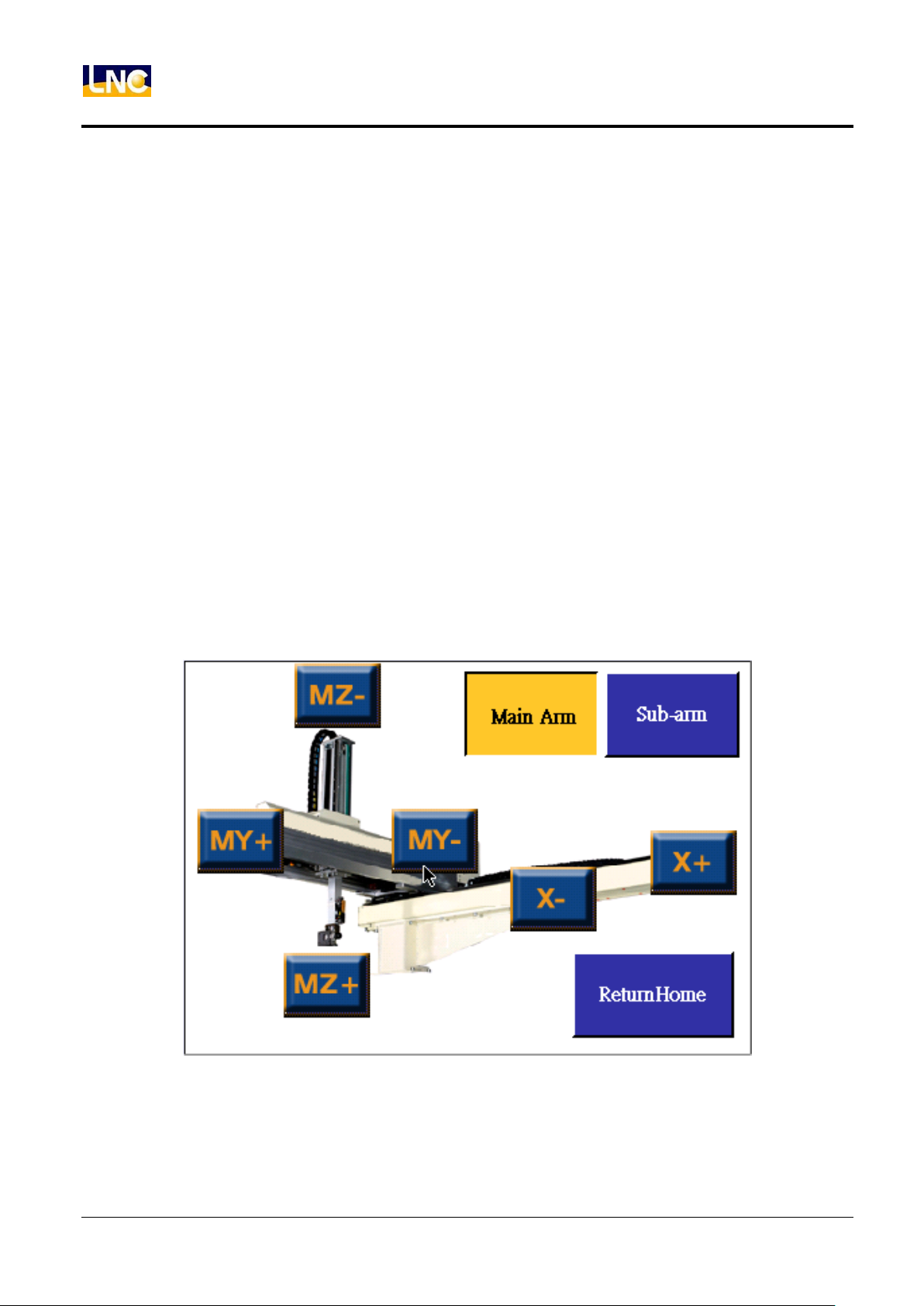
3 axis servo system axis name and definition
Horizontal axis:X。
Pull axis:MY。
Vertical axis:MZ。
Direction as below。
IV
LNC Technology Co., Ltd.
Page 7
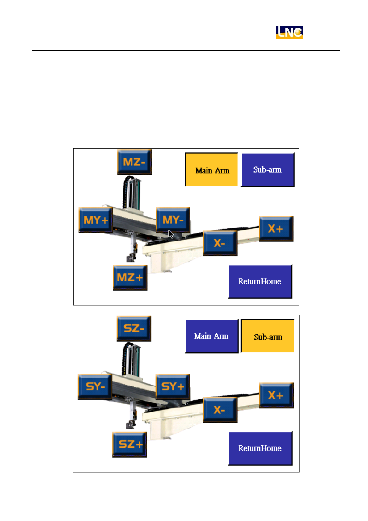
5 axis servo system axis name and definition
Horizontal axis:X。
Main arm pull axis:MY。
Main arm vertical axis:MZ。
Sub arm pull axis:SY。
Sub arm vertical axis:SZ。
Direction as below。
LNC-R6000
Table of content
V
LNC Technology Co., Ltd.
Page 8

Page 9
1 Operation Interface
H
G E B C A D F
LNC-R6000
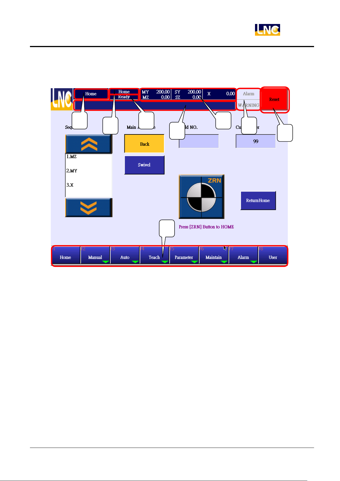
Operation Interface
A:Page Name:Show current page name.
B:Mode:Current mode, there are HOME, MDI, AUTO, TEACH.
C:Situation:Current situation, there are READY, RUNNING, PAUSE.
D:Message hint:System will show hint message at this line.
E:Coordinate of axis.
F:Alarm/warning hint message, where there is a alarm/warning, the area will be twinkling.
G:Reset:Press this button to make robot to be ready and clear alarm.
H:Function key:Switch mode, page. Those with green arrow have further function keys.
1
LNC Technology Co., Ltd.
Page 10
LNC-R6000
Home
2 Home
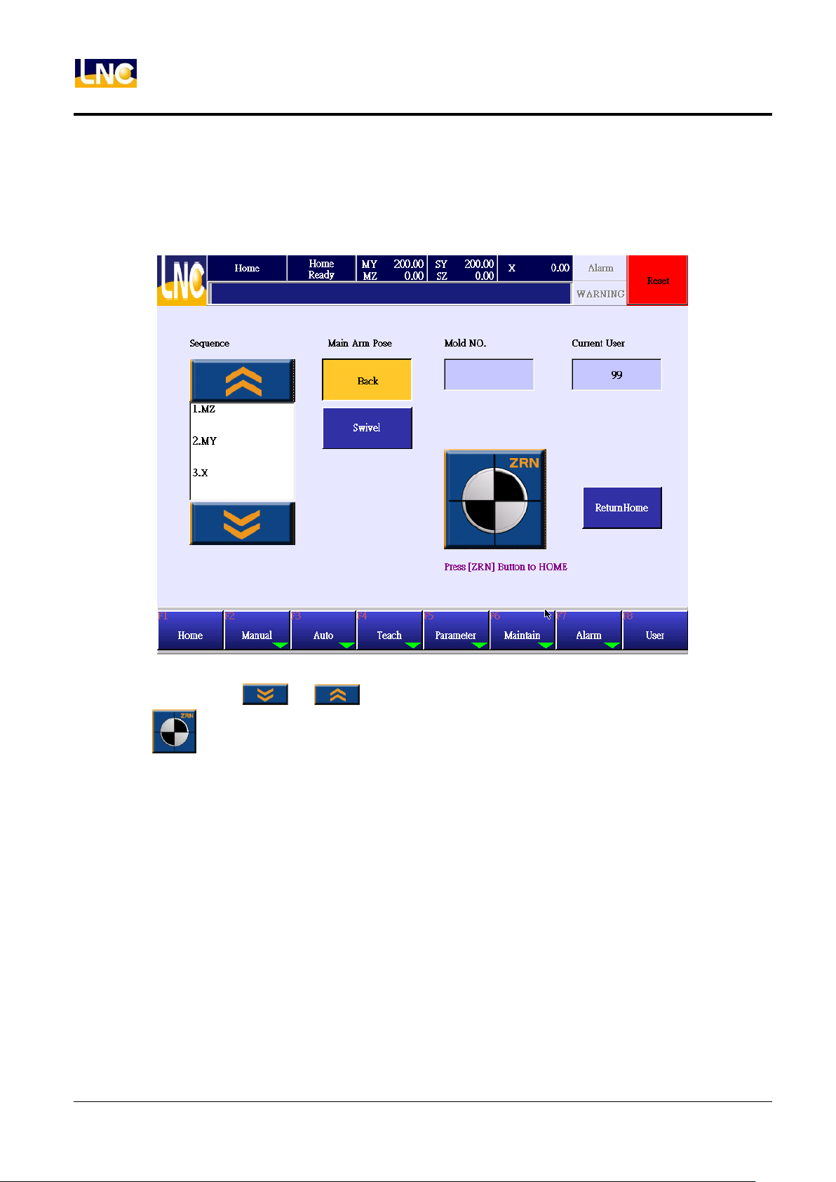
2.1 How to return home
When entering system, you will see Home page.
1. Return posture can be selected before going back, with【vertical】or【horizontal】.
2. Select axis and press or to adjust order to return home.
3. Press to return home.
4. If there is error, press【RESET】or EMG to stop return HOME.
5. When returning home, buttons on this page will be lock. After returning, buttons will be recovered to prevent
wrong operation.
2
LNC Technology Co., Ltd.
Page 11
3 MANUAL
Press【MANAUL】to go to manual mode.
3.1 MANUAL
LNC-R6000
MANUAL
3.1.1 Output
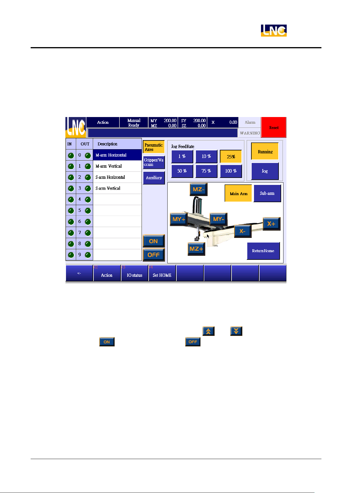
1. There are 3 groups of OUTPUT, air axis, gripper/vacuumer, and peripheral devices. You need to choose
group and select OUTPUT you want to open or close.
2. When OUTPUT amount is bigger then 1 page, you can press and to change.
3. After selecting, press to make this OUTPUT, or to close.
3
LNC Technology Co., Ltd.
Page 12
LNC-R6000
MANUAL
3.1.2 Manual continuous axis move mode
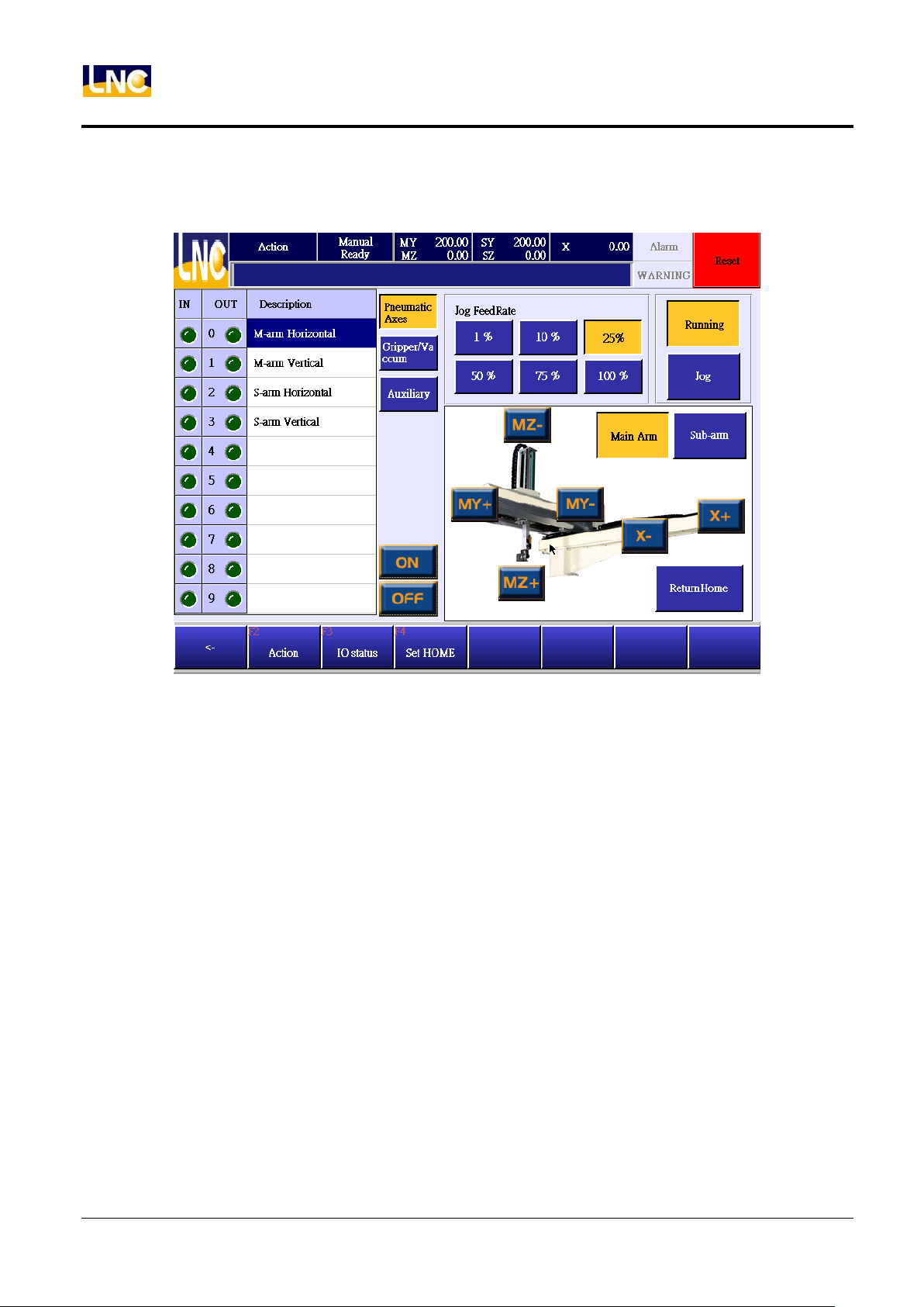
Press axis move button to move continously, release button to stop.
1. Press【Continue】button.
2. Select speed that you want this robot to move.
3. Press corresponding axis t move continuously, release to stop.
4
LNC Technology Co., Ltd.
Page 13
LNC-R6000
MANUAL
3.1.3 JOG
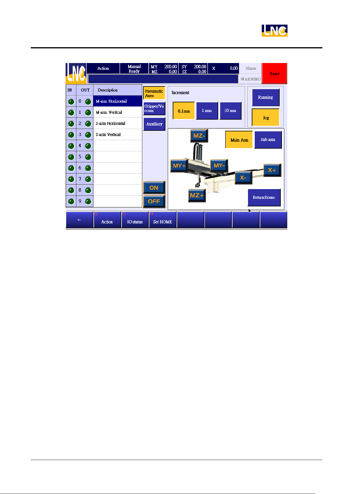
Press axis move button to move by 0.1mm、1mm or 10mm. If you release the button, the axis will stop
immediatelly.
1. Press【JOG】button.
2. Press 0.1mm、1mm、10mm to change movement distance.
3. Axis movement speed is the same to the one continously.
4. Press the button of the axis you want to move, release button to stop.
3.1.4 Return to standby
1. Robot can only return standby point when under【READY】.
2. Press【Return standby】button.
a. X axis is inside mold:the order is YZvertical/horizontal X.
b. X axis is not inside mold:the order is Z vertical/horizontal YX.
3. Standby point can be adjusted at【Adjust standby point】page.
5
LNC Technology Co., Ltd.
Page 14
LNC-R6000
MANUAL
3.2 IO status
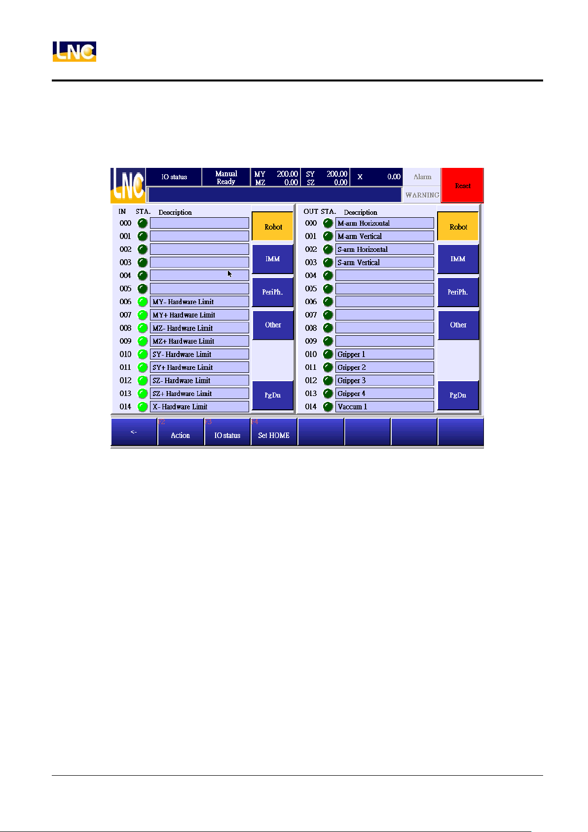
1. INPUT and OUTPUT are devided into group type, press corresponding group button to select I/O list.
2. You can check INPUT and OUTPUT at the same time.
6
LNC Technology Co., Ltd.
Page 15
LNC-R6000
MANUAL
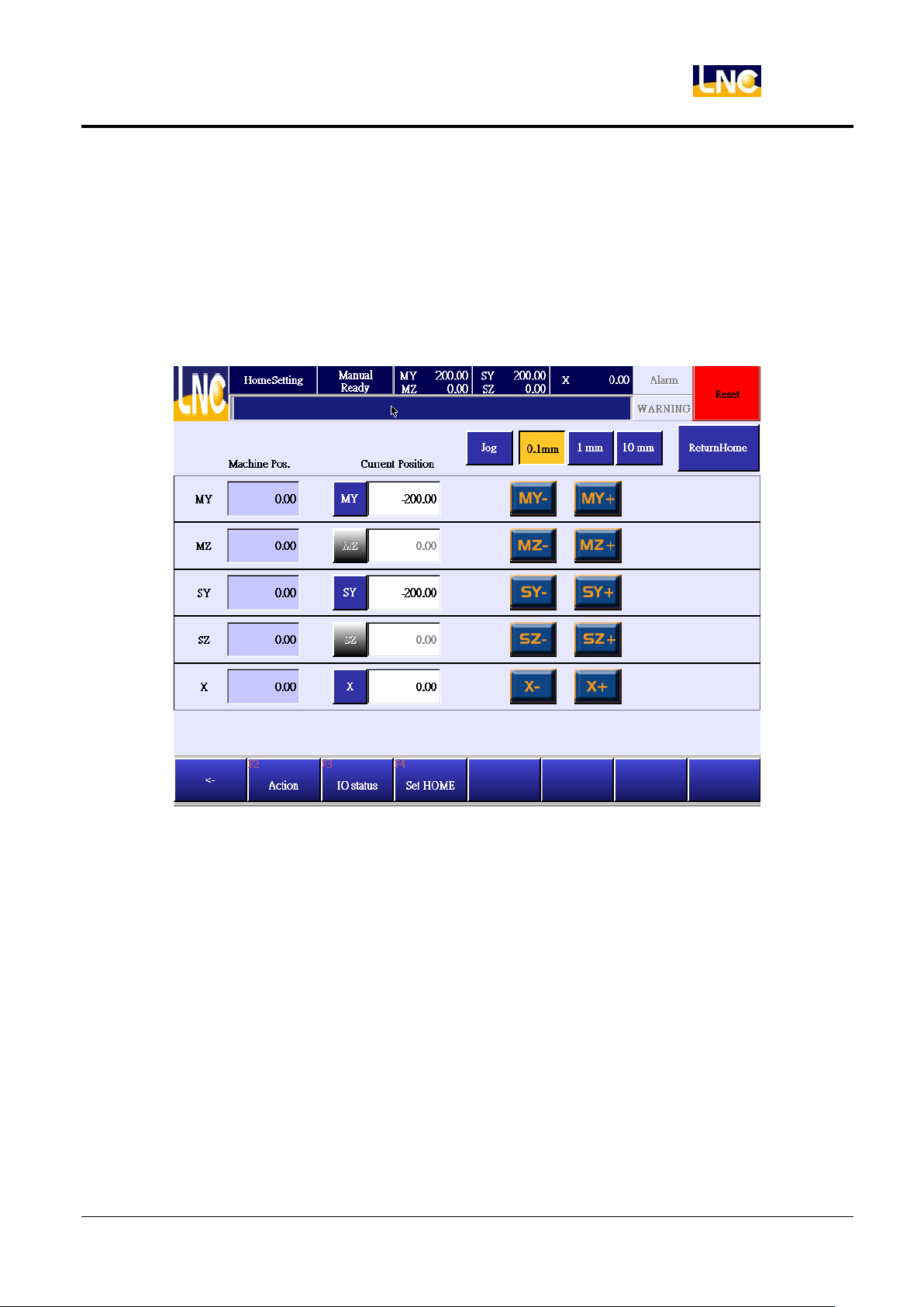
3.3 Standby tuning
How to adjust program ZERO location.
When the program zero point is not the one you want, you can adjust standby point to the program starting point.
When pressing【return standby】, every axis will move to pre-set position.
Home tuning value will be saved at mold file, when opening a new mold file, previous setting will be loaded in, so
the previous offset will be loaded in too.
7
LNC Technology Co., Ltd.
Page 16
LNC-R6000
Auto
4 Auto
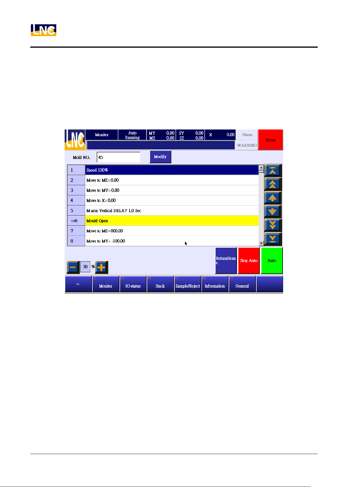
Press【Auto】to go auto mode.
4.1 Monitor
Show auto running situation under auto mode.
8
LNC Technology Co., Ltd.
Page 17
4.1.1 Button Description
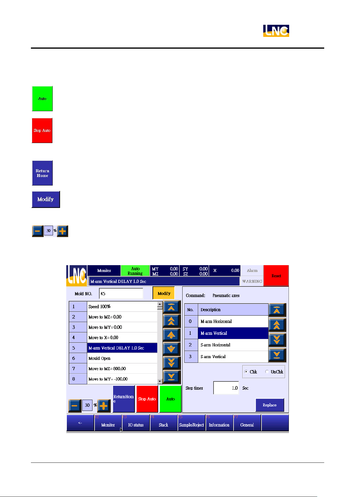
:Run auto cycle.
:When the step is at【complete open mold】, press this button to stop. But if you press this button when
the step is at middle travel, system will complete the whole travel and stop.
:Let robot return to standby point.
:Under auto running, page and cursor will be moved by current program. If you want to modify
LNC-R6000
Auto
program,you can press modify key to stop auto mode.
:Running speed adjustment under auto mode.
4.1.2 Modify program under auto running.
Under auto mode, you can only modify movement speed, delay time and small tuning of axis location.
1. Move cursor to the place you want to change.
9
LNC Technology Co., Ltd.
Page 18
LNC-R6000
Auto
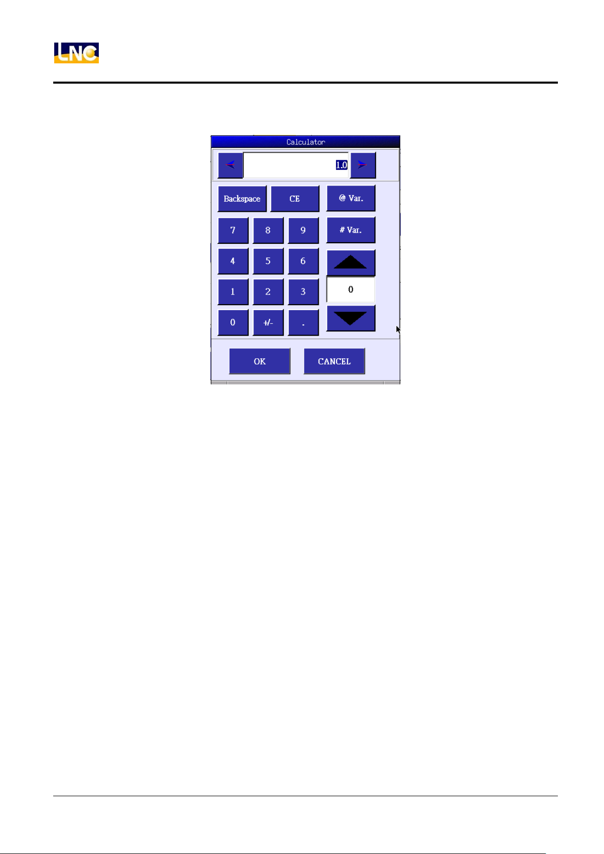
2. Press【modify】to see right side selections and key in dealy time to see below small tablet.
3. Key in value and press【OK】
4. Press【REPLACE】at right down side to take over old program.
4.2 IO status
Refer to chapter 3.2.
4.3 Stack setting
Refer to chapter 5.3.
4.4 Sample/reject
Refer to chapter 5.4.
10
LNC Technology Co., Ltd.
Page 19
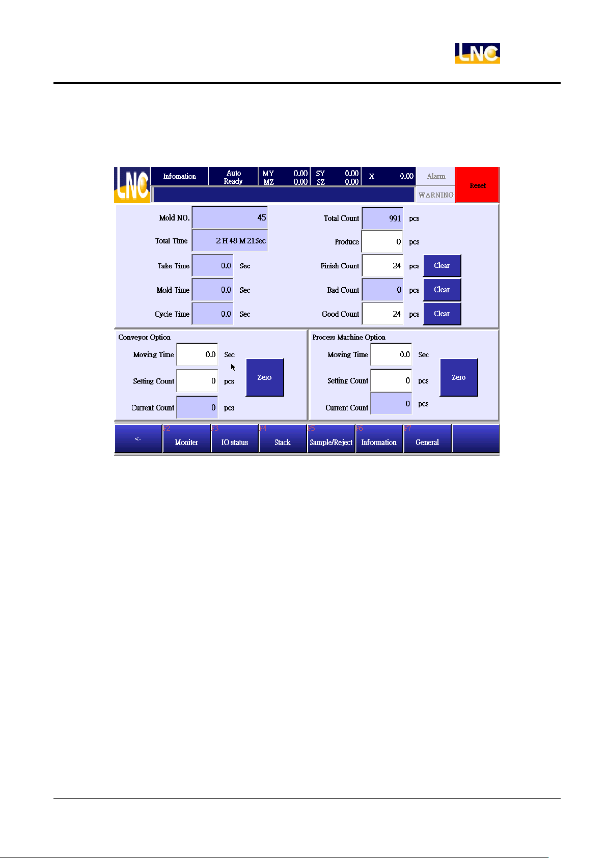
4.5 Cycle monitor
You can see time and parts setting under auto mode.
LNC-R6000
Auto
Mold number:Mold file name.
Total time:Accumulated operation time.
Take time:The take out time is from completing open mold, robot pick goods to returning to original location.
Mold time:The time for injection molding machine to complete a part.
Cycle time:The time that robot to complete to pick a part.
Total count:The total auto loop times for robot to running.
Finish count:If the setting is 100, when the auto loop meets 100 times, system will send warning to notice. If the
setting is 0, this function will be fail.
Good count:Acceptable parts total numbers.
Bad count:Total times of rejecting parts signals.
Produce:The total amount of injection parts, including good and bad parts.
11
LNC Technology Co., Ltd.
Page 20
LNC-R6000
Auto
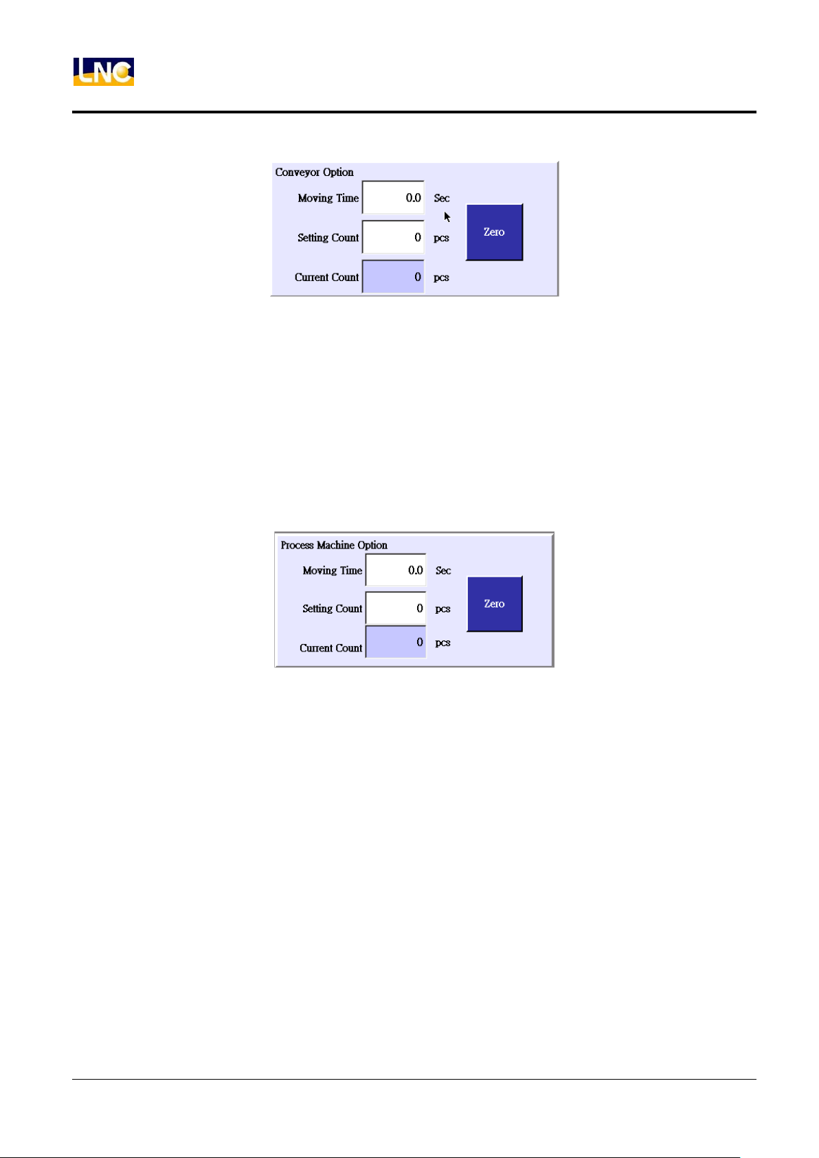
4.5.1 Conveyor setting
Moving time:This is to set up converyor stop time. When this is 0 and parts also arrived, conveyor will not stop.
Setting count:After how many molds, conveyor will start to move. When this is 0, conveyor will not move.
Current count:Show current put times. You can press【return zero】to reset this value and force conveyor to
move.
The way to use conveyor is to write command for conveyor in the program and set up moving time and interval
mode at this page. When running times arrive, conveyor will move for some time and stop.
4.5.2 Process machine setting
Moving time:This is to set up working machine stop time. When this is 0 and parts also arrived, conveyor will
not stop.
Setting count:After how many molds, working machine will start to move. When this is 0, working machine will
not move.
Current count:Show current put times. You can press【return zero】to reset this value and force working
machine to move.
The way to use working machine is to write command for conveyor in the program and set up moving time and
interval mode at this page. When running times arrive, conveyor will move for some time and stop.
12
LNC Technology Co., Ltd.
Page 21
LNC-R6000
Teach
5 Teach
Press【Teach】to go to teach mode.
This mode is to do mold file editing and running test.
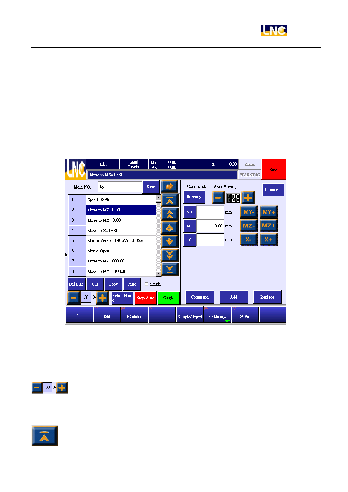
5.1 Edit
User default level is 99, this level can only open file and do cycle start. If you want to edit or modify program, you
will need to change to level 29 and above.
5.1.1 Function key Delete:Delete cursor current program. Cut:Cut cursor current program. Copy:Copy cursor current program. Paste:Insert the program that you copy or cut.
running speed tuning:running speed tuning under teach mode. Default is 30%.
Single:Run total program one time and stop. At the next step, press this function to do single cycle.
Stop Auto:Stop robot running and go to stop status.
Show index page.
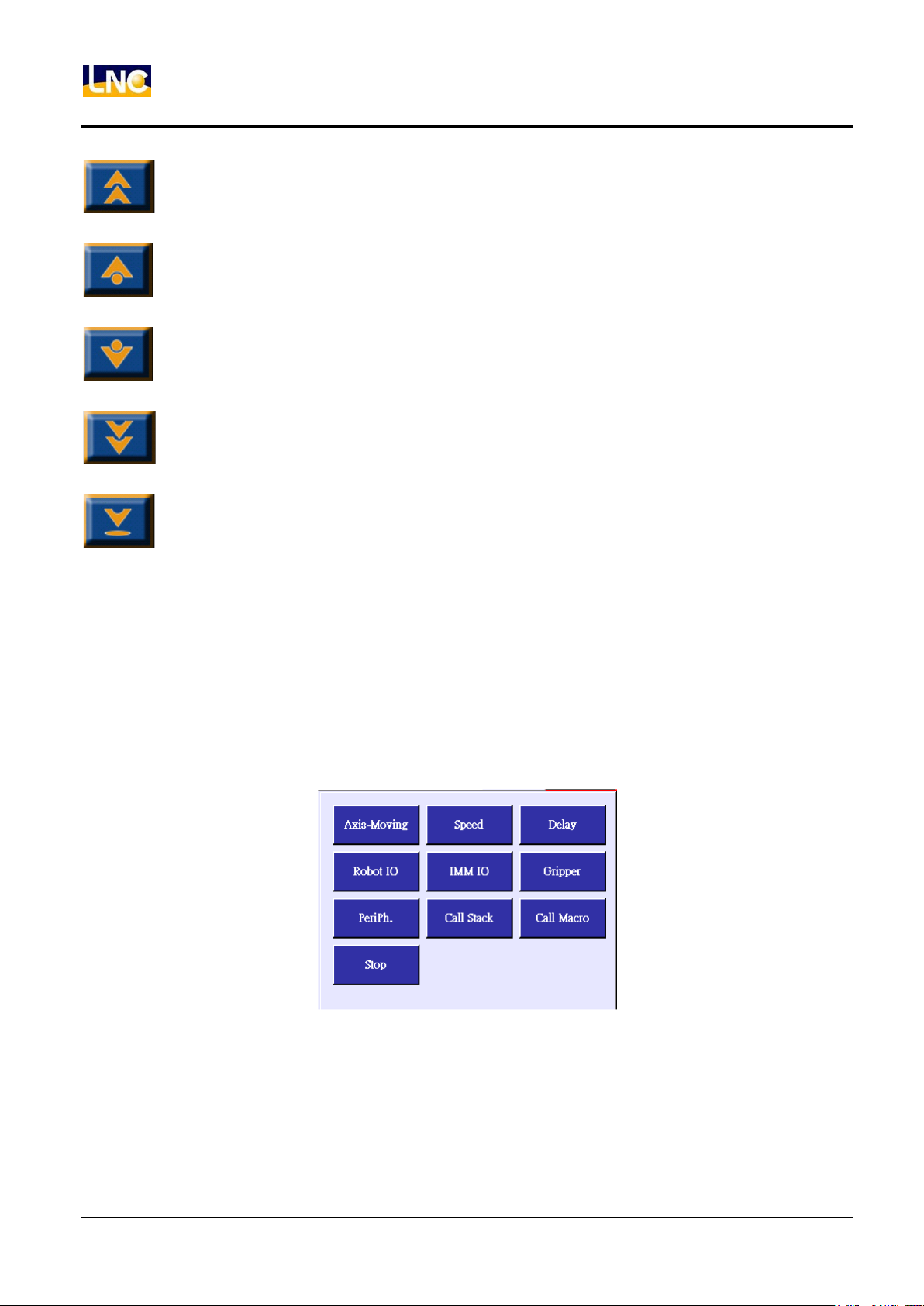
13
LNC Technology Co., Ltd.
Page 22
Teach
LNC-R6000
Show previous page.
Show previous line.
Show next line.
Show next page.
Show last page.
Command:Return to command list page.
Add:Add right side setting info to the left side’s next line.
Replace:Make left side blue line to replace to current setting info.
5.1.2 Program command detail
Go to TEACH and press【command】, you will see teach command as below. Press below button to go to this
command’s page.
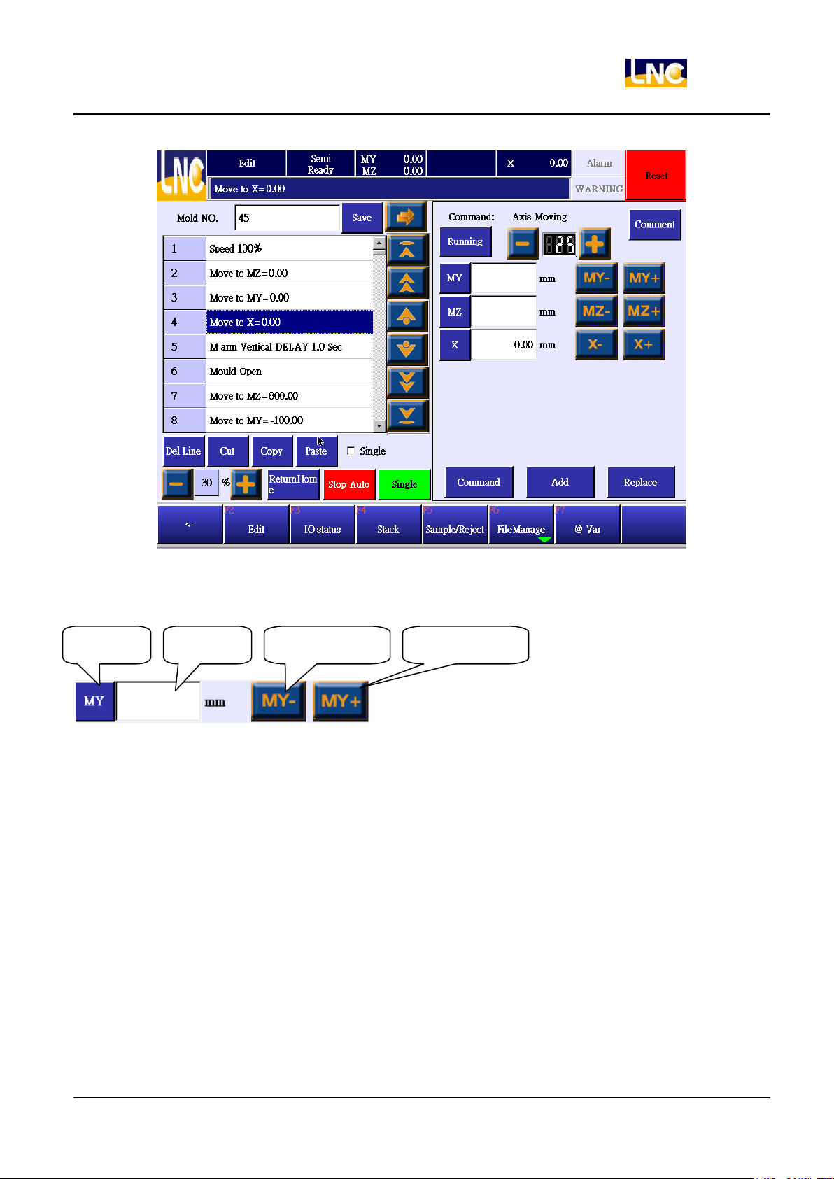
5.1.3 Axis
Press axis to see below.
14
LNC Technology Co., Ltd.
Page 23
LNC-R6000
Axis direction(+)
Axis direction(-)
Axis name
location
Teach
This command is to move to certain location.
There are two ways to input location.
Press【location】to see small keypad and key in directly.
Press【axis direction】to move axis to target location and press【location】,【axis name】will pet current location
into location column.
15
LNC Technology Co., Ltd.
Page 24
LNC-R6000
Teach
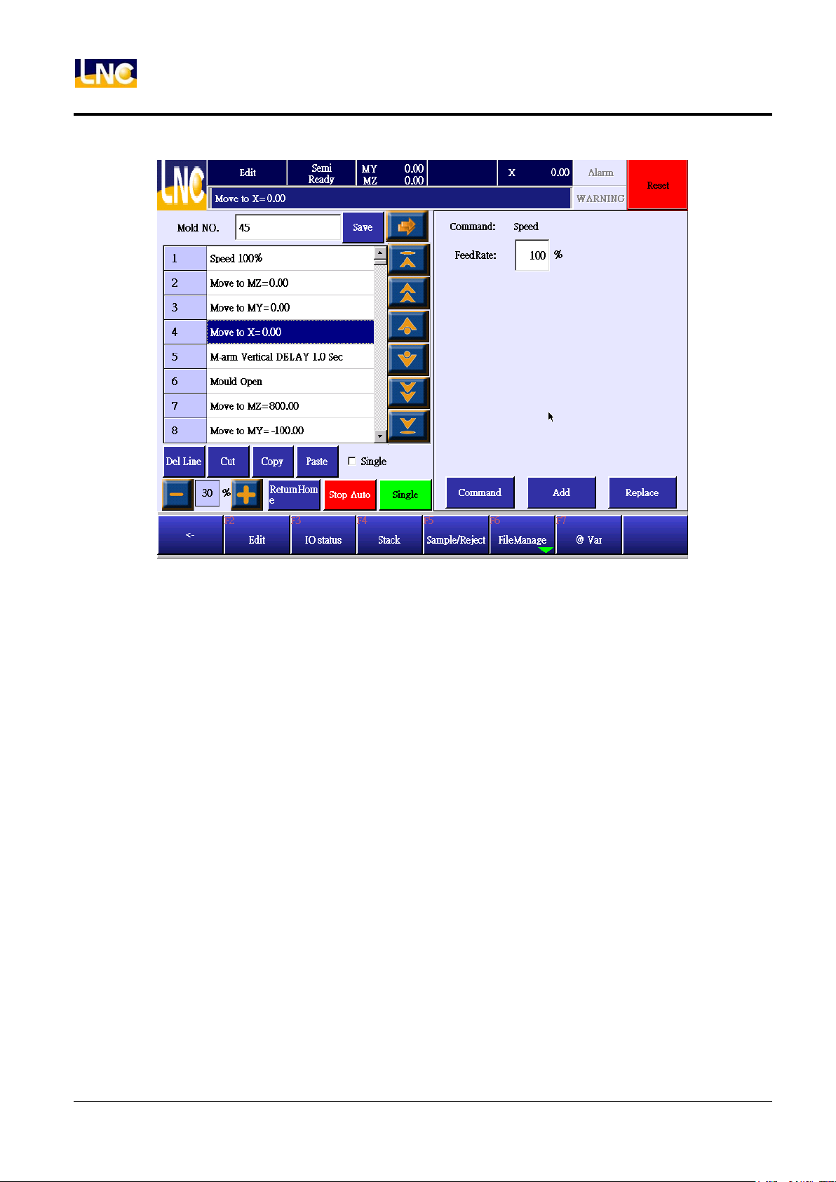
5.1.4 Speed
1. You can set up moving speed for every axis, if you didn’t renew the speed, this speed will be the previous
setting.
2. Range is 1~100.
16
LNC Technology Co., Ltd.
Page 25
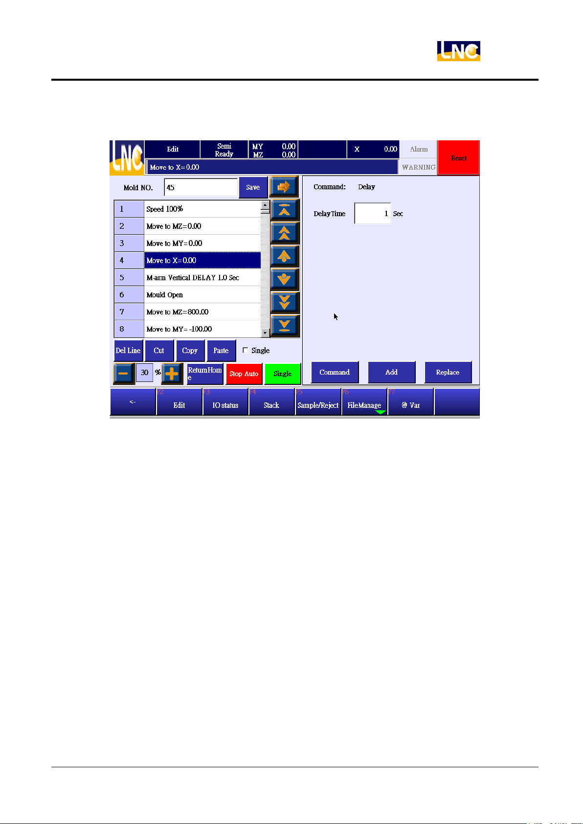
5.1.5 Delay
LNC-R6000
Teach
1. You can set up the delay time to run the next command.
2. Setting range 0~9.9.
17
LNC Technology Co., Ltd.
Page 26
LNC-R6000
Teach
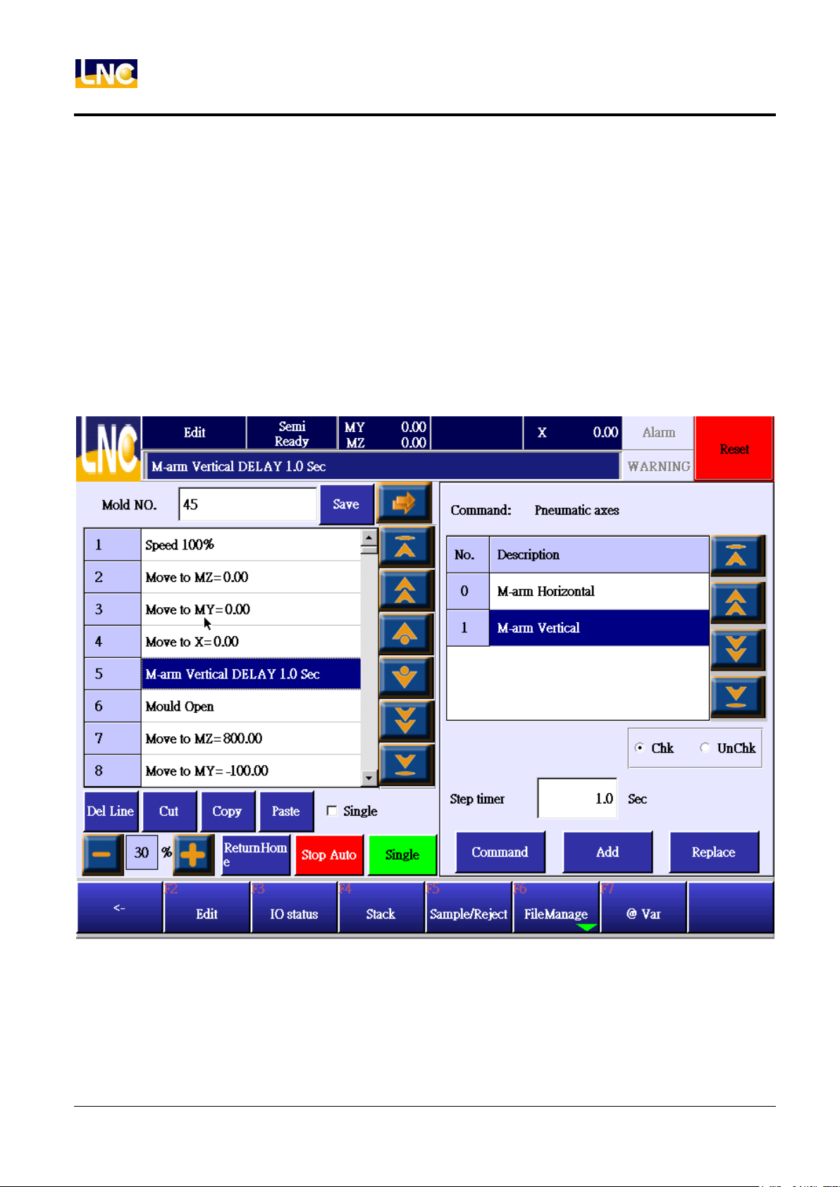
5.1.6 Robot I/O
OUTPUT action.
1. Robot I/O command are output main arm vertical/horizontal, sub-arm move forward/backward, sub-arm
vertical/horizontal, sub-arm move down/move up output points.
2. 【Check/Not check】item is for you to set up a check system. If【Check】, then after an output, system need
to receive an input signal and go next step. If【Not check】】, then after an output, system will run next step
immediately.
3. After completing output signal setting, press【add】to add this command to the next line or press【replace】
to replace cursor line info.
4. Press【add】or【replace】to return to command list.
18
LNC Technology Co., Ltd.
Page 27
LNC-R6000
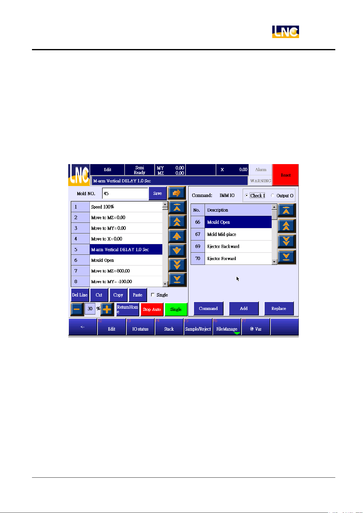
5.1.7 Injection molding machine I/O 【Check INPUT】
1. When running to check injection molding machine input signal, system will stop at this step. Until
corresponding input signal has been trigger and system will go next step.
2. Click【check I】to see below command
3. Select the signal you want to check and press【add】to add command to the next line or press【replace】
to replace cursor info.
4. Press【add】or【replace】to return to command list.
Teach
19
LNC Technology Co., Ltd.
Page 28
LNC-R6000
Teach
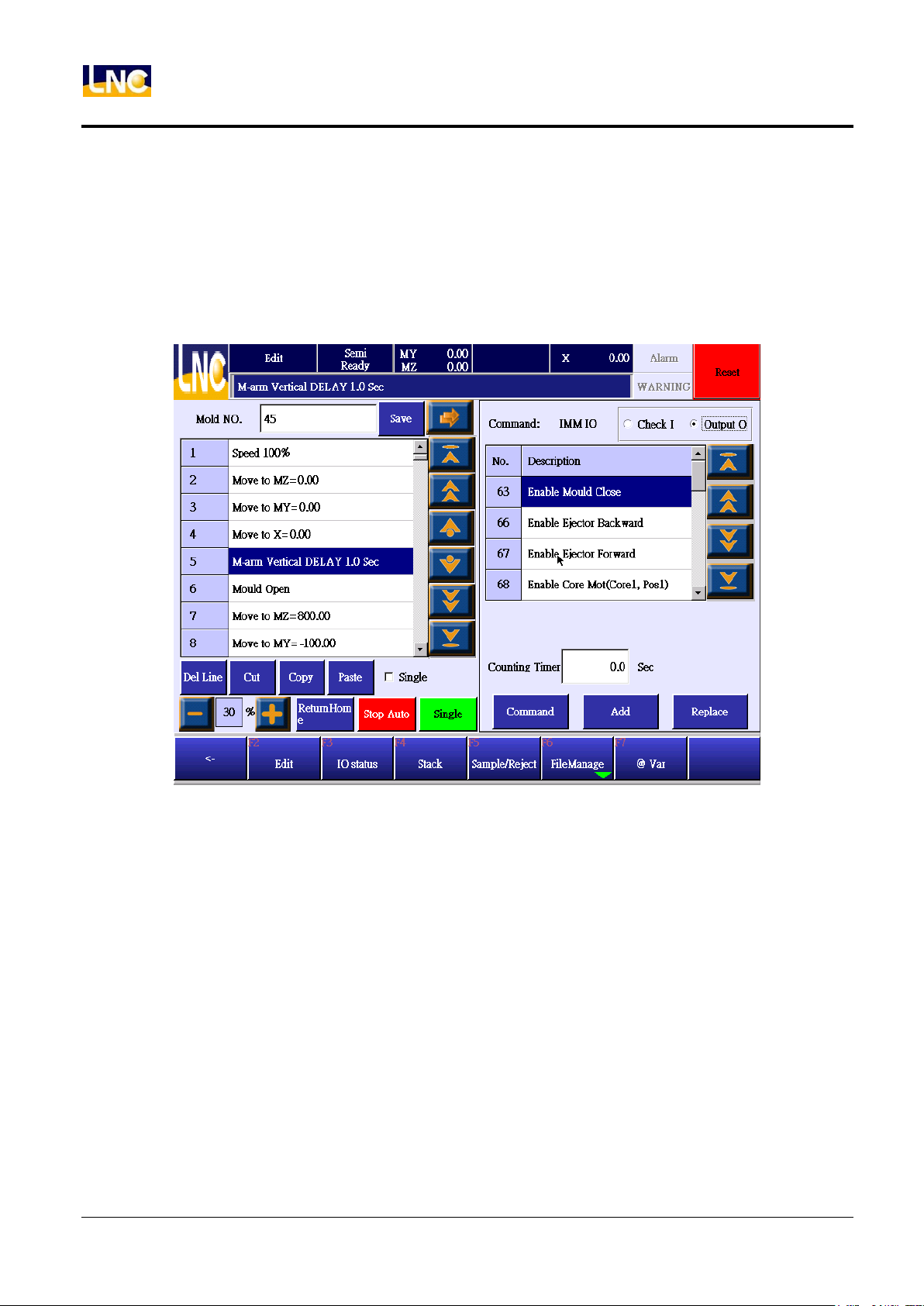
【Check OUTPUT】
1. When running to injection molding machine output signal steps, certain output signal will run next step
immediately. Until output delay time arrives, system will output exact signal.
2. Click【check O】to see below command
3. Select the signal you want to check and press【add】to add command to the next line or press【replace】
to replace cursor info.
4. Press【add】or【replace】to return to command list.
20
LNC Technology Co., Ltd.
Page 29
LNC-R6000
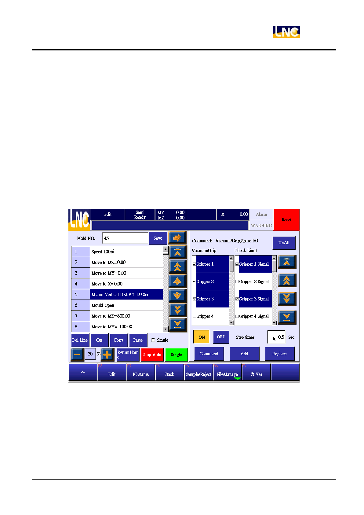
5.1.8 Vacuum/gripper I/O
Output certain action.
1. Select the vacuumer or gripper valve.
2. When choosing vacuumer or gripper valve, if you do not want to check corresponding I point, cancel
【vacuumer/gripper valve check】.
3. ON is output signal, OFF is close the signal.
4. Set up delay time, and then run output signal.
5. Under auto mode, click【vacuumer/gripper check】, while robot arm moved up to safety position, the
corresponding Input signal did not trigger, system will send warning and stop robot. After clearing this trouble,
you can press auto cycle to run, but under signal cycle, this situation will not trigger warning.
6. Press【add】to add command to the next line or press【replace】to replace cursor info.
7. Press【add】or【replace】to return to command list.
Teach
21
LNC Technology Co., Ltd.
Page 30
LNC-R6000
Teach
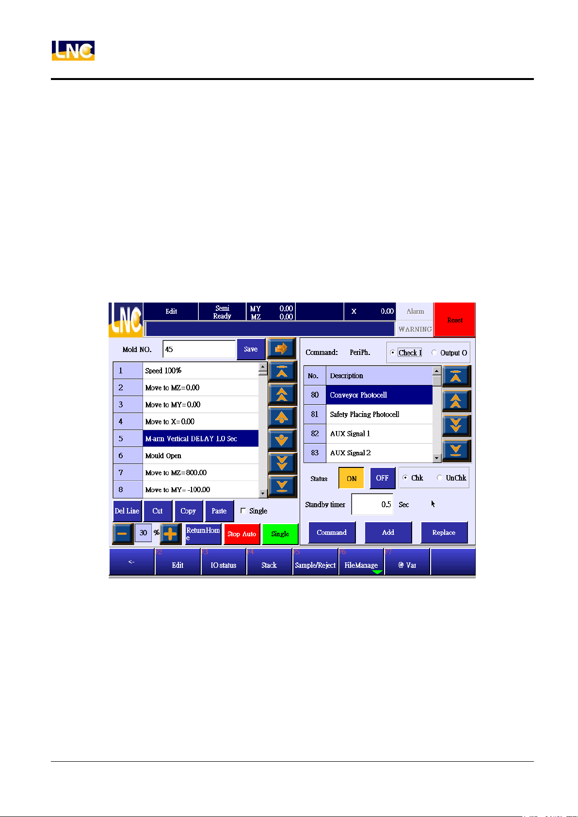
5.1.9 Peripheral device I/O
【Check I】
1. When running to steps of check peripheral device I/O, system will wait corresponding Input signal to be
triggered and then go next step. But if the waiting time is bigger than the setting maximum time, system
will send warning. Under check mode, if you press running function key again, system will still send
warning, but if under not check mode, program will run next step.
2. Select【check I】to see below command.
3. Press【add】to add command to the next line or press【replace】to replace cursor info.
4. Press【add】or【replace】to return to command list.
22
LNC Technology Co., Ltd.
Page 31
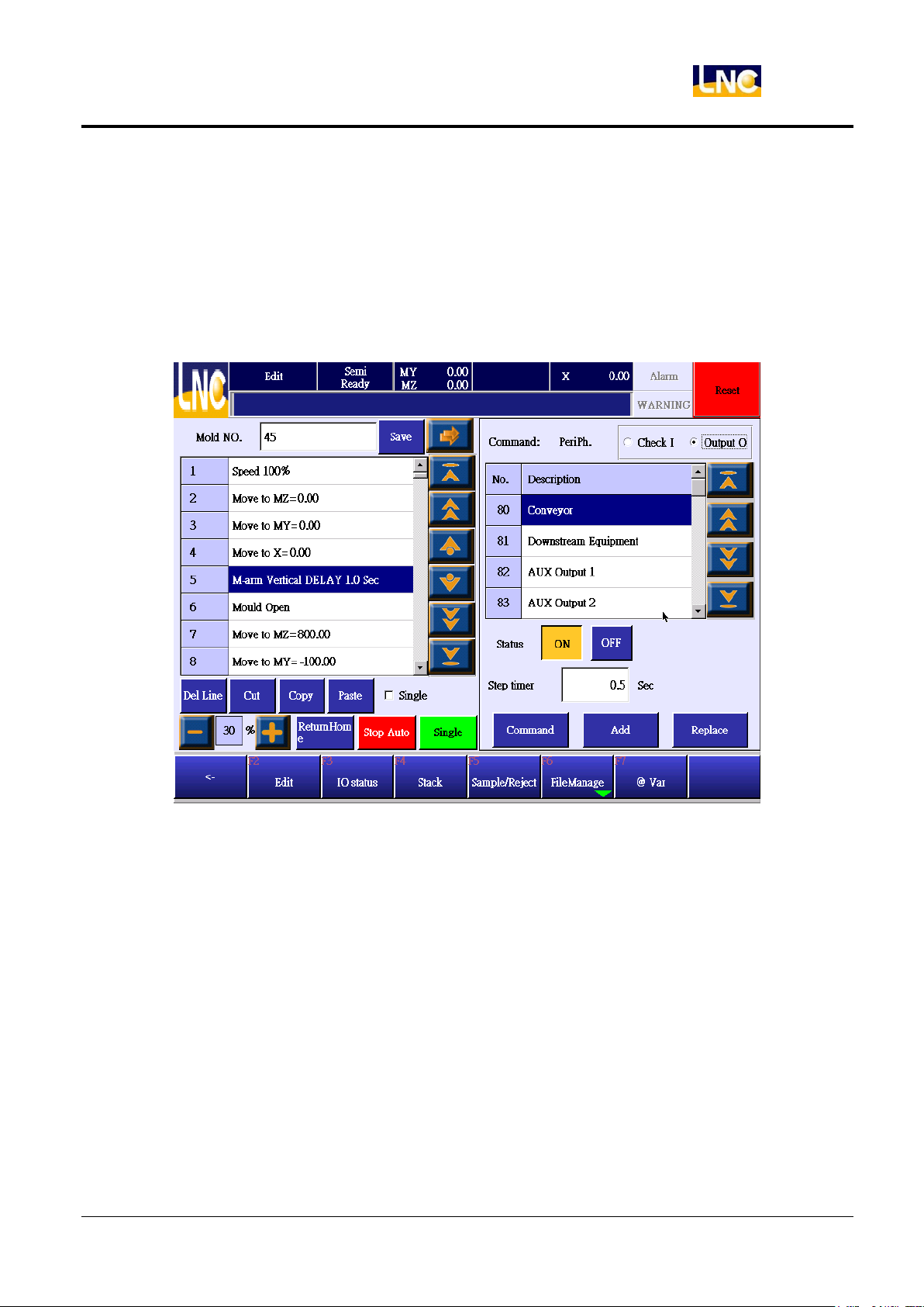
【Output O】
These are the peripheral device output.
1. Choose output signal and choose signal status is ON/OFF.
2. Set up how long you want to delay and run this output.
3. Press【add】to add command to the next line or press【replace】to replace cursor info.
4. Press【add】or【replace】to return to command list.
LNC-R6000
Teach
23
LNC Technology Co., Ltd.
Page 32
LNC-R6000
Teach
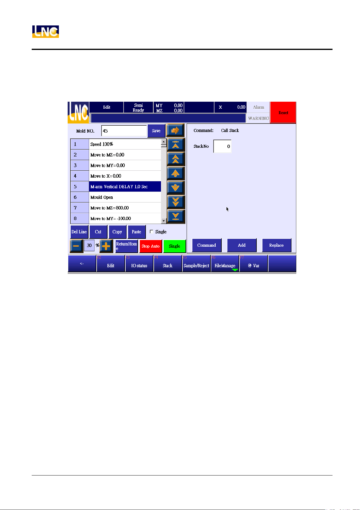
5.1.10 Call stack
Array number is 0~9, array setting content is based on【stack setting】page.
24
LNC Technology Co., Ltd.
Page 33
LNC-R6000
Teach
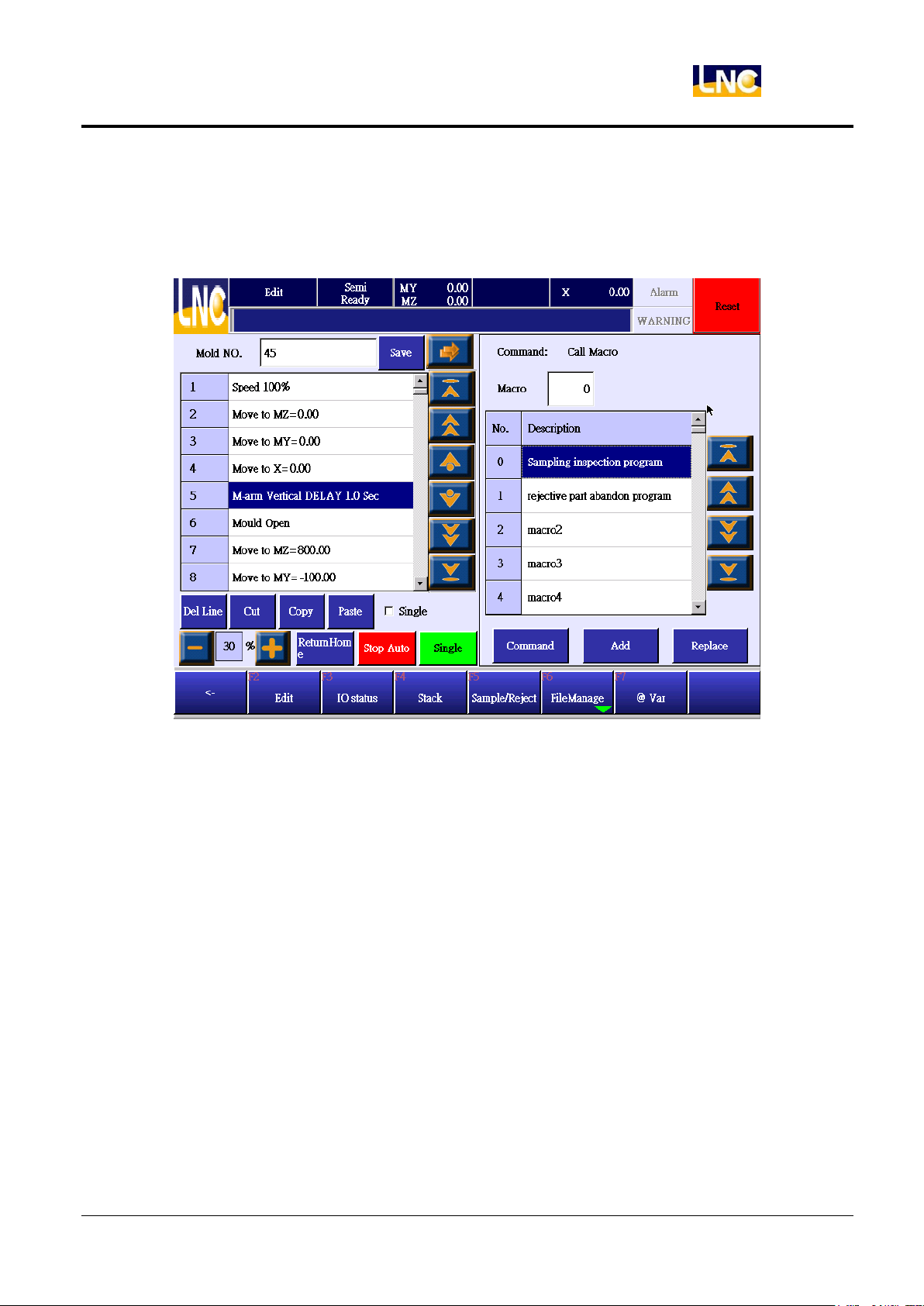
5.1.11 Call MACRO
This macro will be edited by machine makers, is for main program to call. System offers total 100 groups of
MACRO for you to write. Refer to【MACRO】chapter.
Self-defined MACRO file name list
1. Run【backup】to backup file to USB drive, backup info should include MACRO. Refer to【backup】chapter
to know more.
2. Use word editing program(EX:Word)to open file under this link, backup\ncfiles\macro0000.str in the USB
drive.(Simplified Chinese=modify this file, macro0001.str, English=modify this file, macro0002.str).
3. File content is as below
[HMIstring]
2300=sampling check program
2301=rejecting item give up program
2302=sub program 2
2303=sub program 3
2304=sub program 4
2305=sub program 5
2306=sub program 6
…
2398=sub program 98
2399=sub program 99
25
LNC Technology Co., Ltd.
Page 34
LNC-R6000
Teach
[HMIstring]<==first line is system setting keyword; this line should be exist no matter any language.
File format content must be【number=sub program name】.
Number range 2300~2399 to correspond to sub program 0~sub program 99, total 100 groups of sub
program.
4. After modification, via【backup】function to upload this new file into USB drive. Upload to file to controller,
reboot to see the new modification.
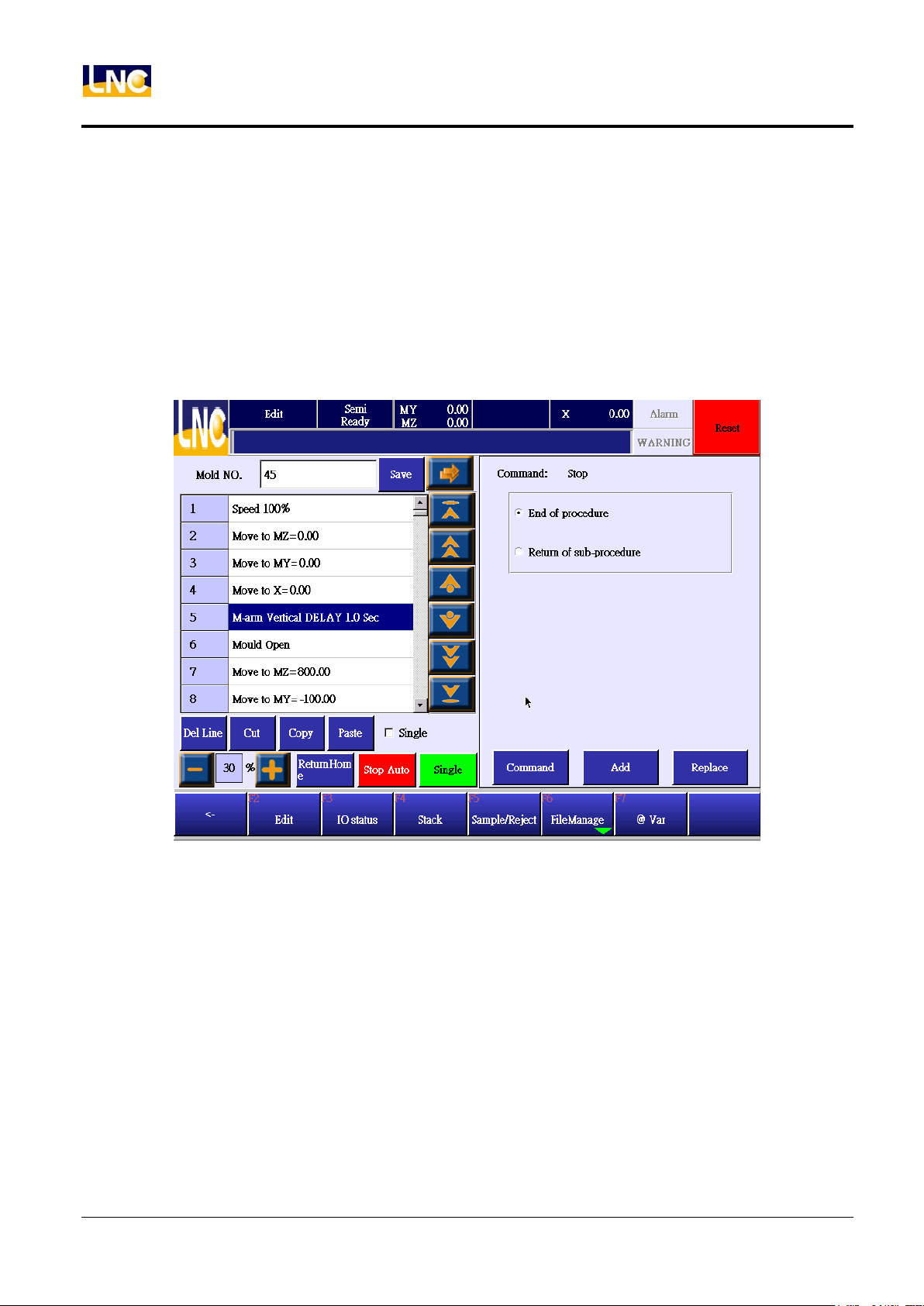
5.1.12 Stop
How to set up program ending.
1. Teach program’s last step must be(also call main program)program end. When runs to this step, there will
have below situation.
a. Teach mode:program ends and stops.
b. Auto mode:Running from the first line of program.
2. Sub program’s last line could be
a. Sub program return:after sub program completing, it will continue to call later program.
b. Program ends:after sub program ending, it will start from the first line of main program.
3. When running to program ends or sub program return, later command will not be run.
26
LNC Technology Co., Ltd.
Page 35
LNC-R6000
Teach
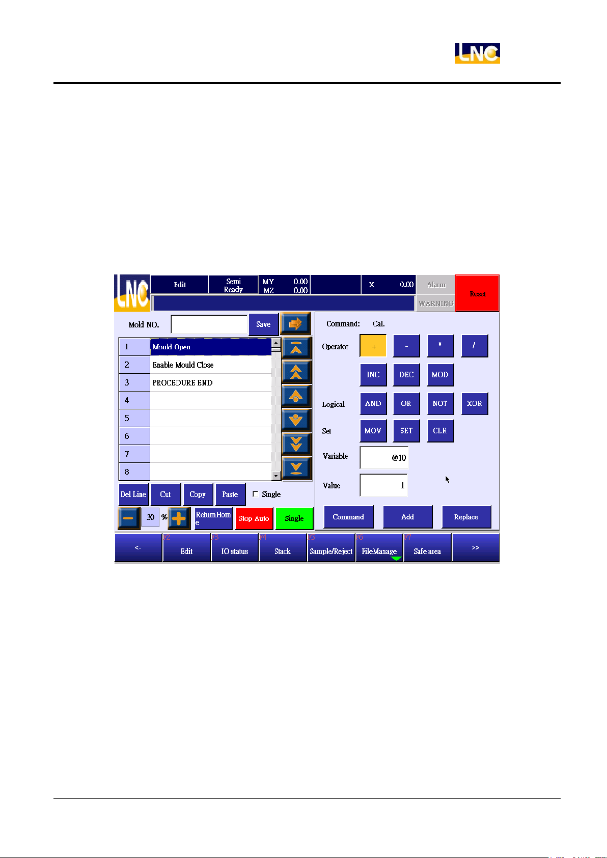
5.1.13 Calculating
There are 1100 mutual variables in the system. Mutual variable can be read and set up in main program and sub
program. You can use mutual variable to meet special function in the program. There are calculating type, logic
type and setting type.
Calculating type:add, subtract, multiply, and divide.
Logic type:system offers 32 bit variables, there are AND、OR、NOT、XOR for bit processing.
Setting type:MOV will make variable to be certain value;SET will make variable to be 1;CLR will make
variable to be 0.
27
LNC Technology Co., Ltd.
Page 36
LNC-R6000
Teach
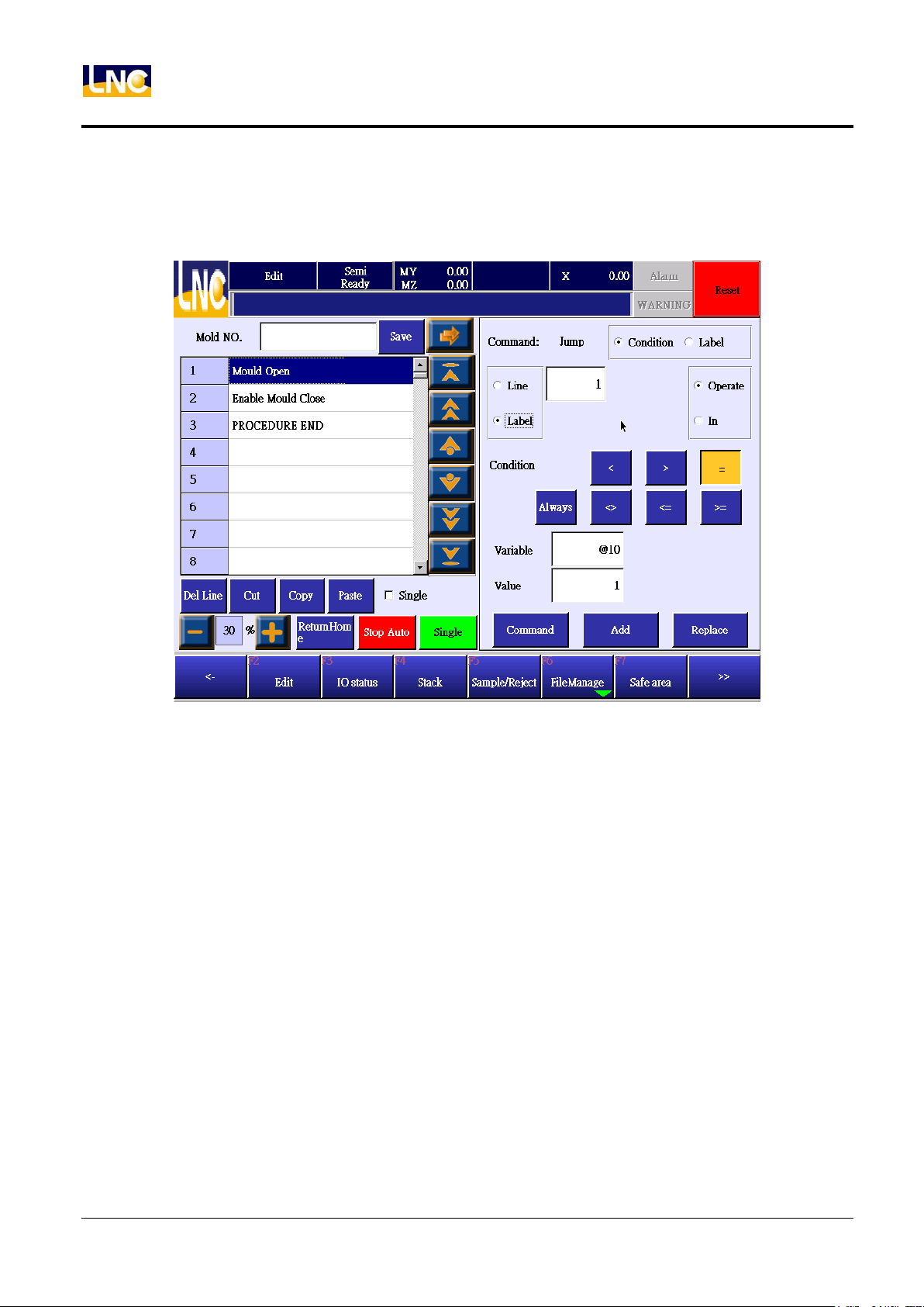
5.1.14 Jump
Press【Jump】to go to below. Jump function can be certain line number or certain tag.
Jump to line number
1. Click line number.
2. Key in line number.
3. Choose jump by variable calculating or I status.
a. calculating:determine@variable value status.
Conditional are as below
unconditional
less than (<)
bigger than (>)
equal to (=)
is not equal to (<>)
bigger than or equal to (<=)
less than or equal to (> =)
b. I:determine current I signal is ON or OFF.
28
LNC Technology Co., Ltd.
Page 37
LNC-R6000
Teach
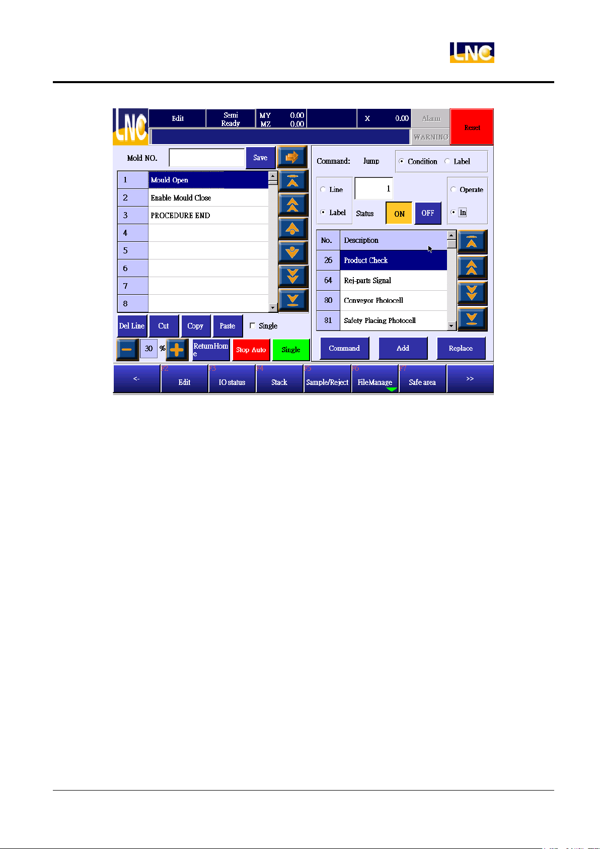
4. Presses [add] to add to the next line or press replace to rewrite this line.
5. After pressing, return to command list.
Jump to tag
1. Choose tag item.
2. Key in tag number you want to jump to.
3. Choose jump by variable calculating or I status
a. calculating:determine@variable value status.
Conditional are as below
unconditional
less than (<)
bigger than (>)
equal to (=)
is not equal to (<>)
bigger than or equal to (<=)
less than or equal to (> =)
b. I:determine current I signal is ON or OFF
4. Press [add] to add to the next line or press replace to rewrite this line
5. After pressing, return to command list
6. Move to the target location and press jump button.
29
LNC Technology Co., Ltd.
Page 38
LNC-R6000
Teach
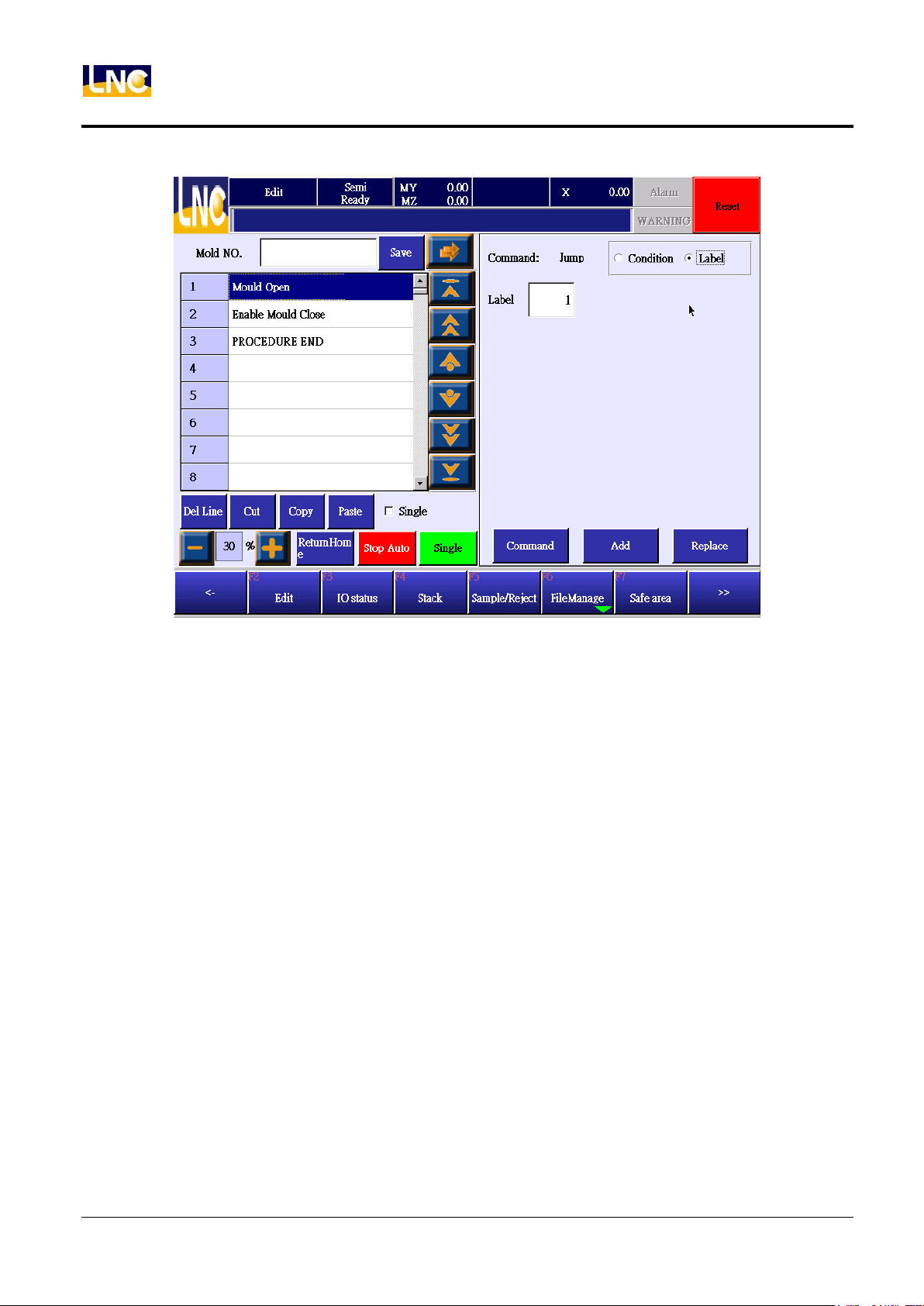
7. Choose label selection.
8. Key in label number, label number definition cannot be repeated.
9. Press [add] to add to the next line or press [replace] to rewrite this line.
30
LNC Technology Co., Ltd.
Page 39
LNC-R6000
Teach
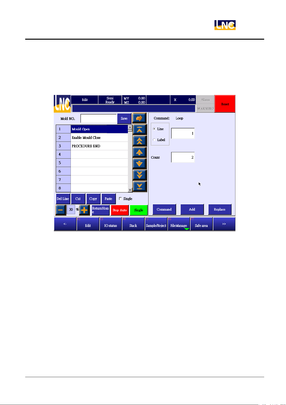
5.1.15 Loop
From certain line number or label location to repeat running certain times. EX:line number=10, repeat times=3,
then the cursor will move from current location to line 10 and run down for 3 times. It means the same area’s
command was run for 4 times.
5.2 IO Status
Refer to chapter 3.2.
31
LNC Technology Co., Ltd.
Page 40
LNC-R6000
Teach
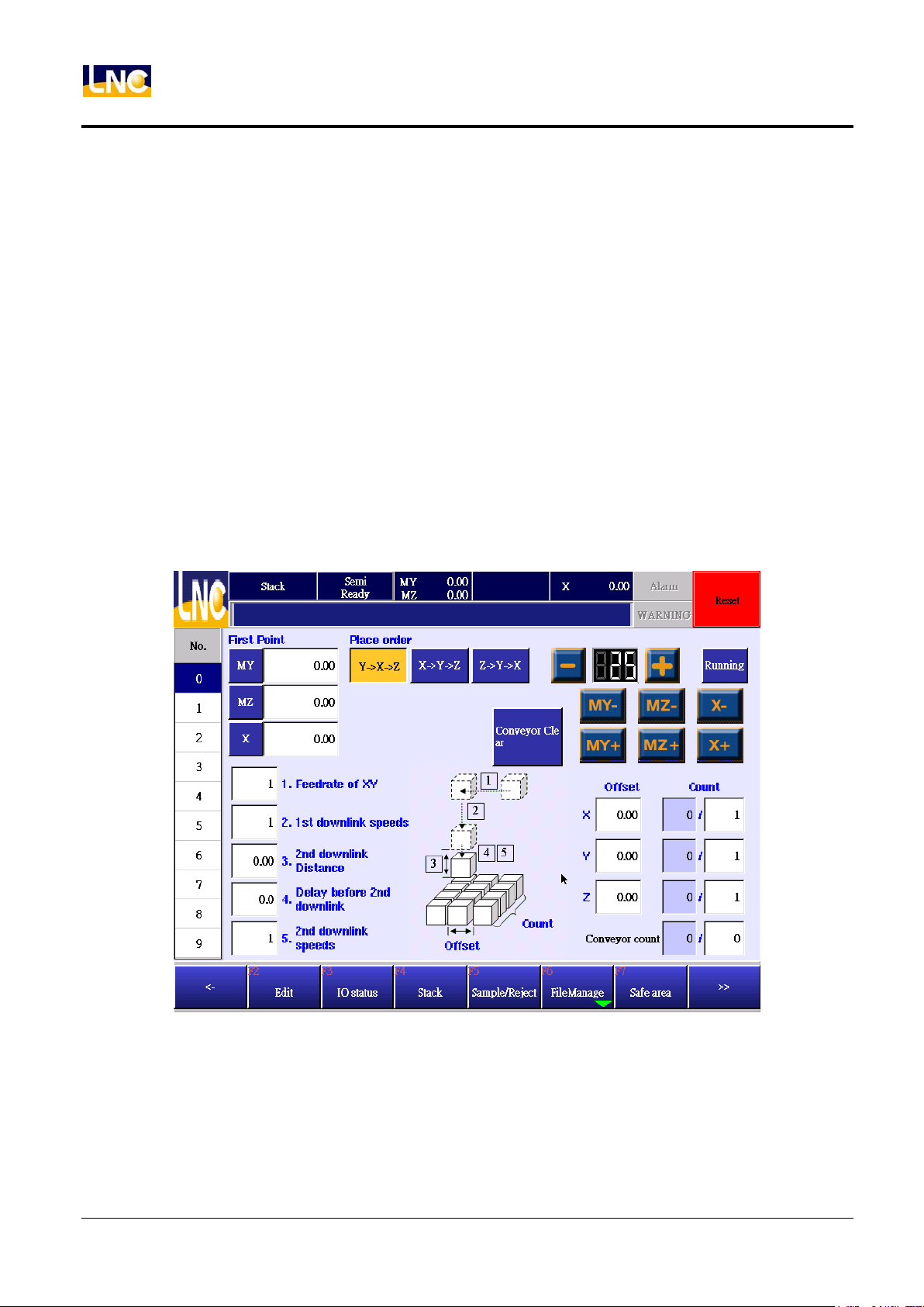
5.3 Stack setting
Press【stack setting】to go current mold document stack setting.
Function Description:
When program runs to【call x number stack】, horizonal axis and pull axis will move to target location and move
down to Z axis location. When comple Z axis, system will continue the next command. As for vacuumer release
and
move-up to safe location, you will need to edit this by yourself.
Notice:
1. Before ssetting stack, confirm current mold name again.
2. Mold document name can not be blank.
3. Before stacking, you will need to move Z axis to certain safe height;after completing, you will also need to do
the same step to prevent collision.
32
LNC Technology Co., Ltd.
Page 41

LNC-R6000
Teach
Operation
Pick number list to switch stack numbers, system offers 10 sets of stack for setting. The number here and teach
mode is corresponding.
First part position:
Set up the first part location, click the colum and input coordinate or press left down side button to make current
location to the setting.
Putting axis order:
Set up axis order of part, press the order directly.
Arm choose:
Main arm or sub arm.
1.The speed to put location(%)
When running stacking, the speed of horizonal axis and pull axis.
2. Z axis goes down 1 section speed(%)
Horizontal axis and pull axis will need to position to the product to be placed above and Z axis will use 1 section
speed to go down to R, EX:part putting location is 500, R distance is 30, Z axis goes down in 1 section speed
with 100%, machine will use 100% to move to 470.
3. Moving distance to go down in 2 section speed(mm)
4.Before going down delay time in 2 section speed(second)
5. Z axis goes down in 2 section speed(%)
When putting parts, if you want to use slow speed to move to target place, ex, moving distance=50, delay time
0.5 second, Z down in 2 section speed=30, if this Z axis target=300, then Z axis will go down in 1 section speed
to 250 ( 250=300-50 ), then delay 0.5 second and use 30% speed to move to Z=300.
Interval
Setting interval of products.
Parts
Left line is to show the complete parts, 0 is the first layer, 1 is the second layer and so on. When running, system
will add up the value. If you want to reset the location, EX, from 3 layer to put, set up value to be 2, from 4 layer to
33
LNC Technology Co., Ltd.
Page 42
LNC-R6000
410
Use main arm or sub arm when sampling
0:Main arm;1:sub arm
411
Traverse axle coordinate when sampling
Unit:mm
412
Crosswise axle coordinate when sampling
Unit:mm
413
Vertical axle coordinate when sampling
Unit:mm
Teach
put, set up value to be 3, and so on, right side is the parts that every axis needs to put.
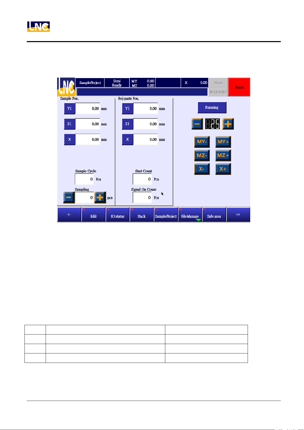
5.4 Sample/reject
5.4.1 Sample check
Sample check cycle:
If you set up this value to be 100 under auto running, every 100 mold, system will put one product to sampling
desk, if you set this to be 0, there is no check.
Manual sample:
Press“+”button to add 1 on manual sampling. When the value is bigger than 0, system will put current product to
sampling check desk and minus value with 1.
@variable number
Sampling function running content should be based on machine maker MACRO 0, moving target location should
be based on above @ variable numbers.
34
LNC Technology Co., Ltd.
Page 43
LNC-R6000
400
Use main arm or sub arm when putting rejecting
0:Main arm;1:sub arm
401
Traverse axle coordinate when putting rejecting
Unit:mm
402
Crosswise axle coordinate when putting rejecting
Unit:mm
403
Vertical axle coordinate when putting rejecting
Unit:mm
Teach
5.4.2 Reject give up
Give up mold when running:
You can set up this value as 10 under auto mode, previous 10 molds will trigger rejecting good signal, value 0
is invalid for this function.
Give up mold when good shape:
When bad shape signal was triggered, you can set up give up goods numbers.
@Variable number
This give up function will need to base on machine maker MACRO 1. Moving target in MACRO will need to
use@to use.
35
LNC Technology Co., Ltd.
Page 44
LNC-R6000
Teach
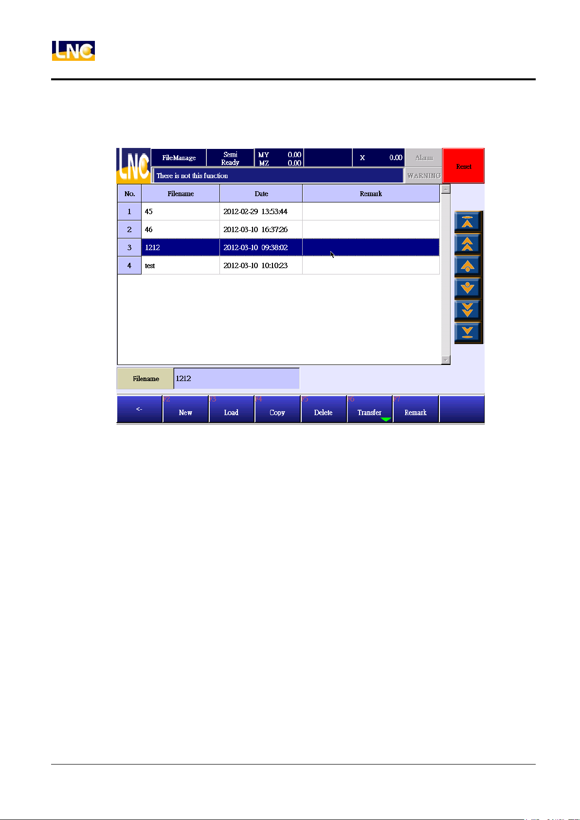
5.5 File manage
Press file to see below.
36
LNC Technology Co., Ltd.
Page 45
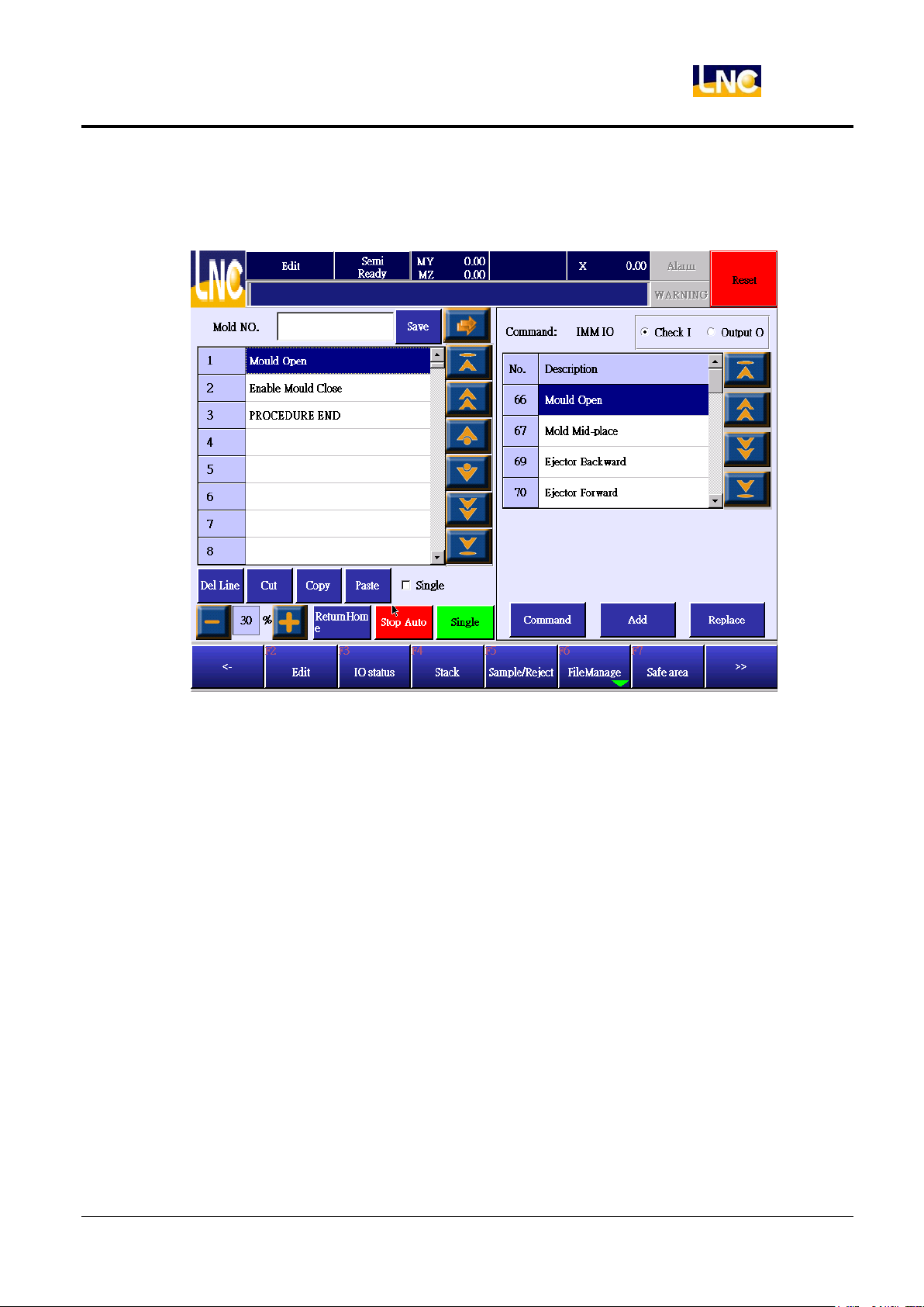
5.5.1 Open a new mold file
1. Press【New】to open a new mold document, as below.
LNC-R6000
Teach
2. Before editing program, you will need to key in mold number.
3. After opening new file, program will have defaul steps, complete open mold, allow close mold, program
end. These command must be exist.
37
LNC Technology Co., Ltd.
Page 46
LNC-R6000
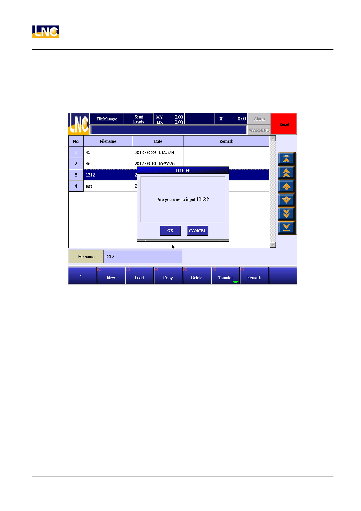
Teach
5.5.2 Read old mold file
1. Select the file you want to open, press【load】.
2. EX, if you choose 45 mold document and press【load】, you will see below confirm window, you can
press【OK】 to open this old file.
38
LNC Technology Co., Ltd.
Page 47
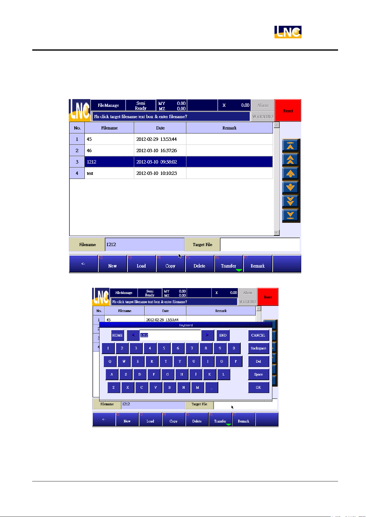
5.5.3 Copy current mold file
1. Choose the file you want to copy, press【copy】, as below.
LNC-R6000
Teach
2. Key in target file name, you will see the new copy file with new name.
3. After inputing, press OK to complete.
39
LNC Technology Co., Ltd.
Page 48
LNC-R6000
Teach
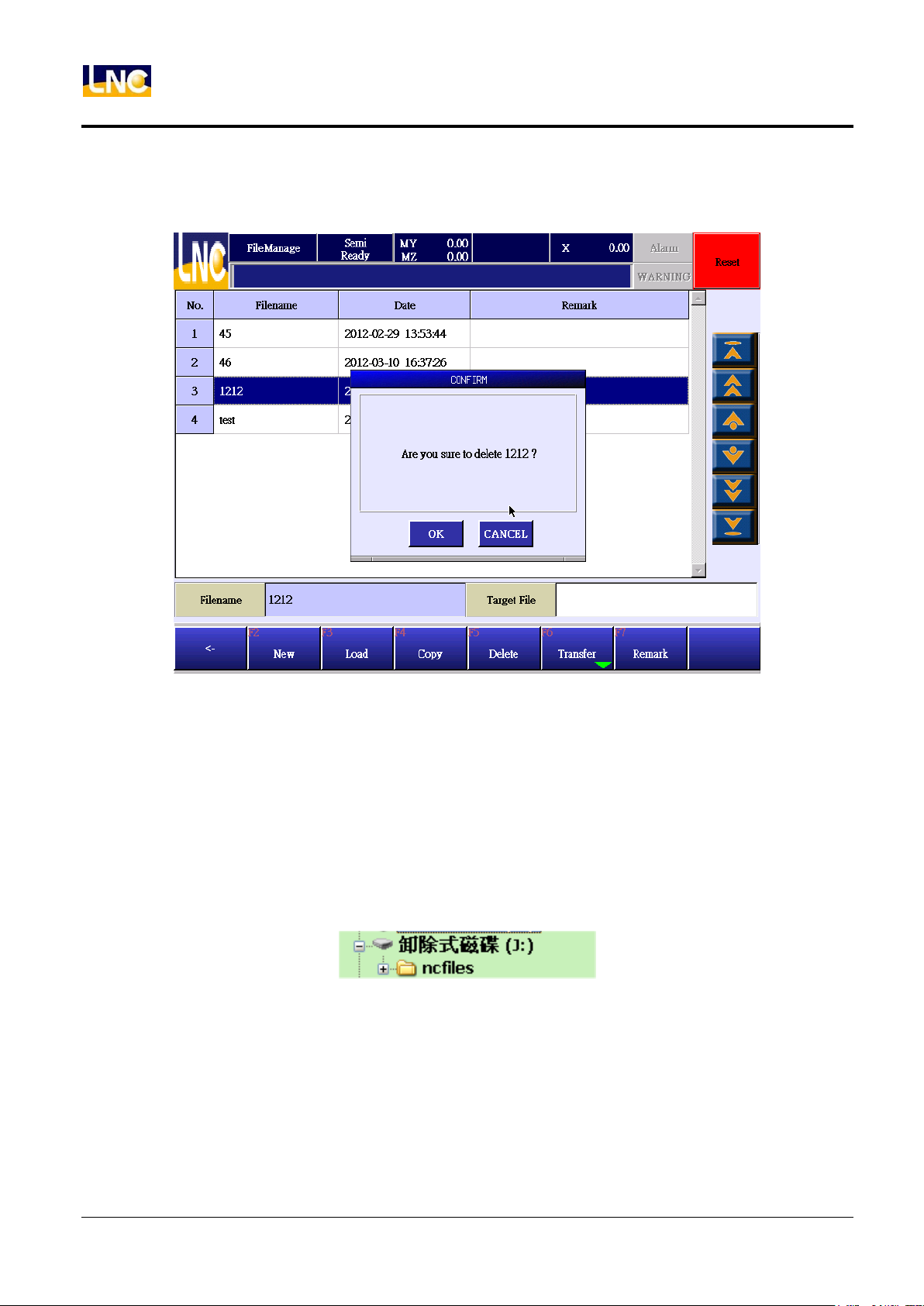
5.5.4 Delete mold file
1. Choose the file you want to delete, press【delete】, there will be a confirm window to confirm with you.
2. Press【OK】to delete this file, if no, press【cancel】.
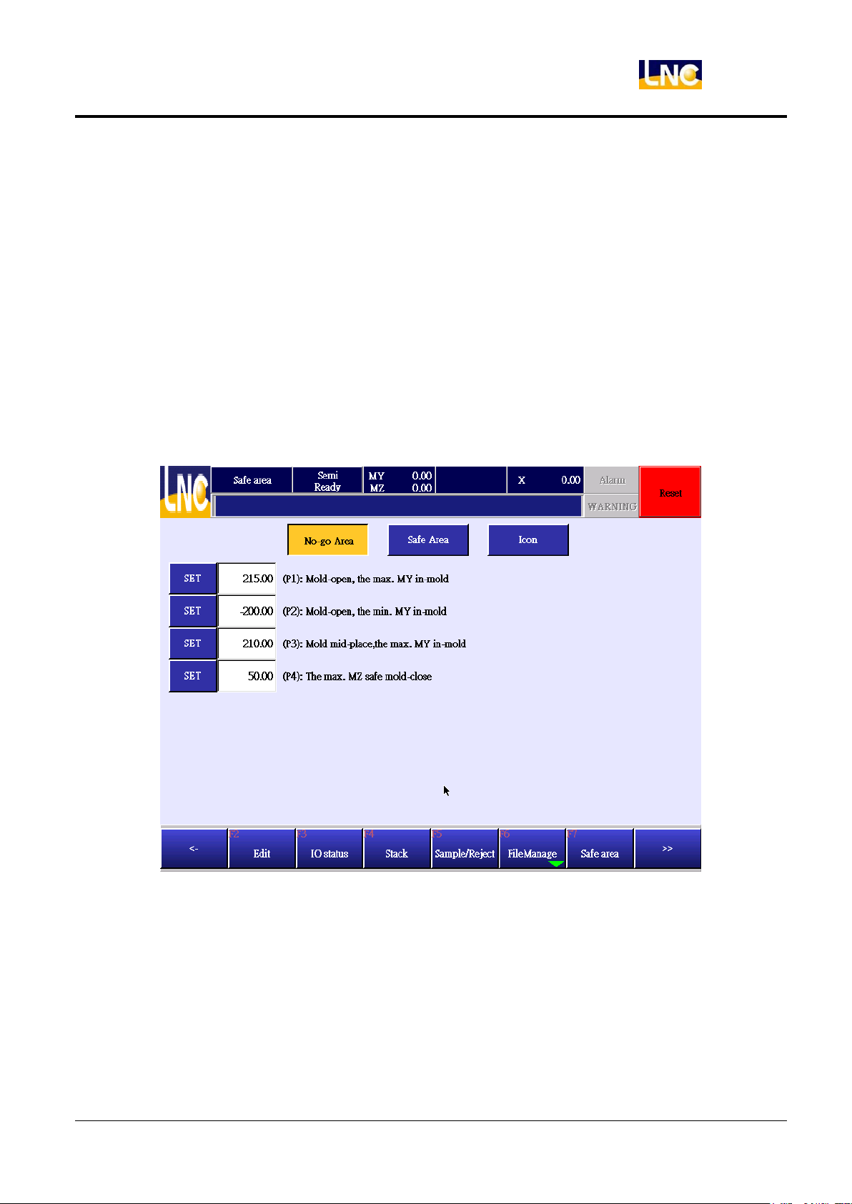
5.5.5 Upload/download mold file via USB
Notice
1. Current, only support 4GB and below USB drive.
2. Import/export file should be under root directoty ncfiles.
3. Directory is as below.
40
LNC Technology Co., Ltd.
Page 49
LNC-R6000
Teach
5.6 Safe area
Function:
In order to prevent collision risk of arm, every mold document has its own safety area setting. When setting up a
new mold document, you will need to confirm the safety area again to meet current mold status.
Notice:
If you set up a new mold file, 【No go area】and【safe area】will use previous mold setting for users to setup
quickly.
5.6.1 No go area setting for 3 axes
41
LNC Technology Co., Ltd.
Page 50
Teach
LNC-R6000
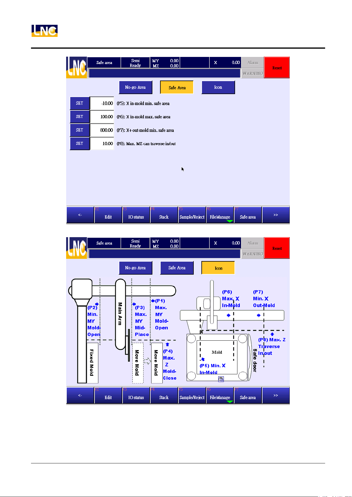
(P1): When completing open mold, max. location of MY axis inside the mold:When completing open
mold, main arm goes down into mold, MY axis goes to the max. coordinate(+), this is P1’s MY coordinate.
(P2): When completing open mold, min. location of MY axis inside the mold :When completing open
42
LNC Technology Co., Ltd.
Page 51

LNC-R6000
Teach
mold,MZ goes down into mold, MY axis goes to the min. coordinate(-), this is P2’s MY coordinate.
(P3): Open mold middle position, max. location of MY axis inside the mold:this function only valid for
open mold middle signal. If there is no this function, you will need to set up the same to MY(P1), When
middle position signal was trigged, MZ axis can go down to mold, when MZ goes to mold, MY axis can
move to the max. location(+), this is P3’s MY coordinate.
(P4): The height for MZ axis to close mold safely:when MZ axis moves up to setting pocition, the max.
down position for mold to close mold.
※This function will only be valid when【go down in mold standby function】, otherwise X axis can only move
to P8 when there is no open mold complete signal.
(P5): X axis in the mold’s min pick safety location:When completing open mold, vertical axis to go down
to mold, the max. location for X axis to move(-)direction.
(P6): X axis in the mold’s max pick safety location:When completing open mold, vertical axis to go into
mold, the max. location for X axis to move(+)direction.
(P7): X axis in (+) direction at safety location outside of mold:the area when vertical axis outside of
mold, when vertical axis to go down, the max. location for X axis to move(-)direction.
(P8): MZ axis to go out safety height:when X axis goes out or in, the max. location that MZ axis will not
hit safety door, this value can not be smaller or equal to 0, recommend value to be 10mm~50mm.
43
LNC Technology Co., Ltd.
Page 52
LNC-R6000
Teach
5.6.2 No go area setting for 5 axes
44
LNC Technology Co., Ltd.
Page 53
LNC-R6000
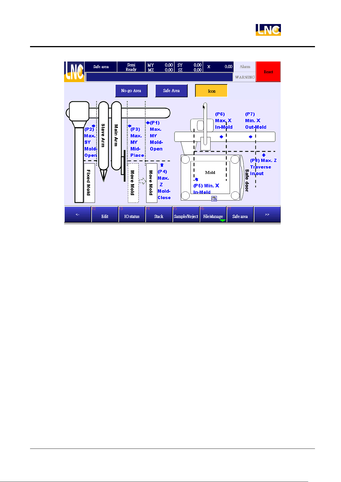
Teach
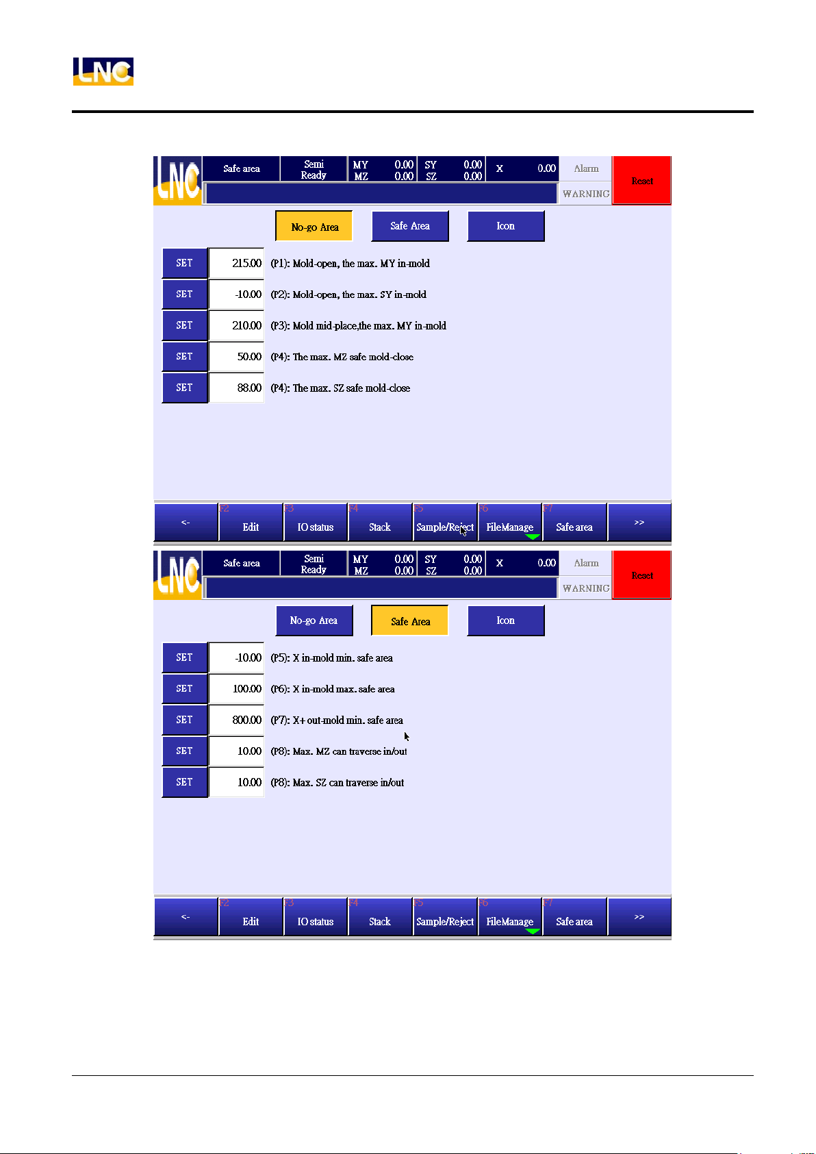
(P1): When completing open mold, max. location of MY axis inside the mold:when completing open
mold, main arm goes down into mold, MY axis goes to the max. coordinate(+), this is P1’s MY coordinate.
(P2): When completing open mold, max. location of SY axis inside the mold:when completing open
mold,SZ goes down into mold, SY axis goes to the max. coordinate(-), this is P2’s SY coordinate.
(P3): Open mold middle position, max. location of MY axis inside the mold:this function only valid for
open mold middle signal. If there is no this function, you will need to set up the same to MY(P1), When
middle position signal was trigged, MZ axis can go down to mold, when MZ goes to mold, MY axis can
move to the max. location(+), this is P3’s MY coordinate.
(P4): The height for MZ axis to close mold safely:when MZ axis moves up to setting pocition, the max.
down position for mold to close mold.
※ This function will only be valid when【go down in mold standby function】, otherwise X axis can only
move to P8 when there is no open mold complete signal.
(P4): The height for SZ axis to close mold safely:when SZ axis moves up to setting pocition, the max.
down position for mold to close mold.
※This function will only be valid when【go down in mold standby function】, otherwise X axis can only move
to P8 when there is no open mold complete signal.
45
LNC Technology Co., Ltd.
Page 54
LNC-R6000
Teach
(P5): X axis in the mold’s min pick safety location:When completing open mold, vertical axis to go down
to mold, the max. location for X axis to move(-)direction.
(P6): X axis in the mold’s max pick safety location:When completing open mold, vertical axis to go into
mold, the max. location for X axis to move(+)direction.
(P7): X axis in (+) direction at safety location outside of mold:the area when vertical axis outside of
mold, when vertical axis to go down, the max. location for X axis to move(-)direction.
(P8): MZ axis to go out safety height:when X axis goes out or in, the max. location that MZ axis will not
hit safety door, this value can not be smaller or equal to 0, recommend value to be 10mm~50mm.
(P8): SZ axis to go out safety height:when X axis goes out or in, the max. location that SZ axis will not hit
safety door, this value can not be smaller or equal to 0, recommend value to be 10mm~50mm.
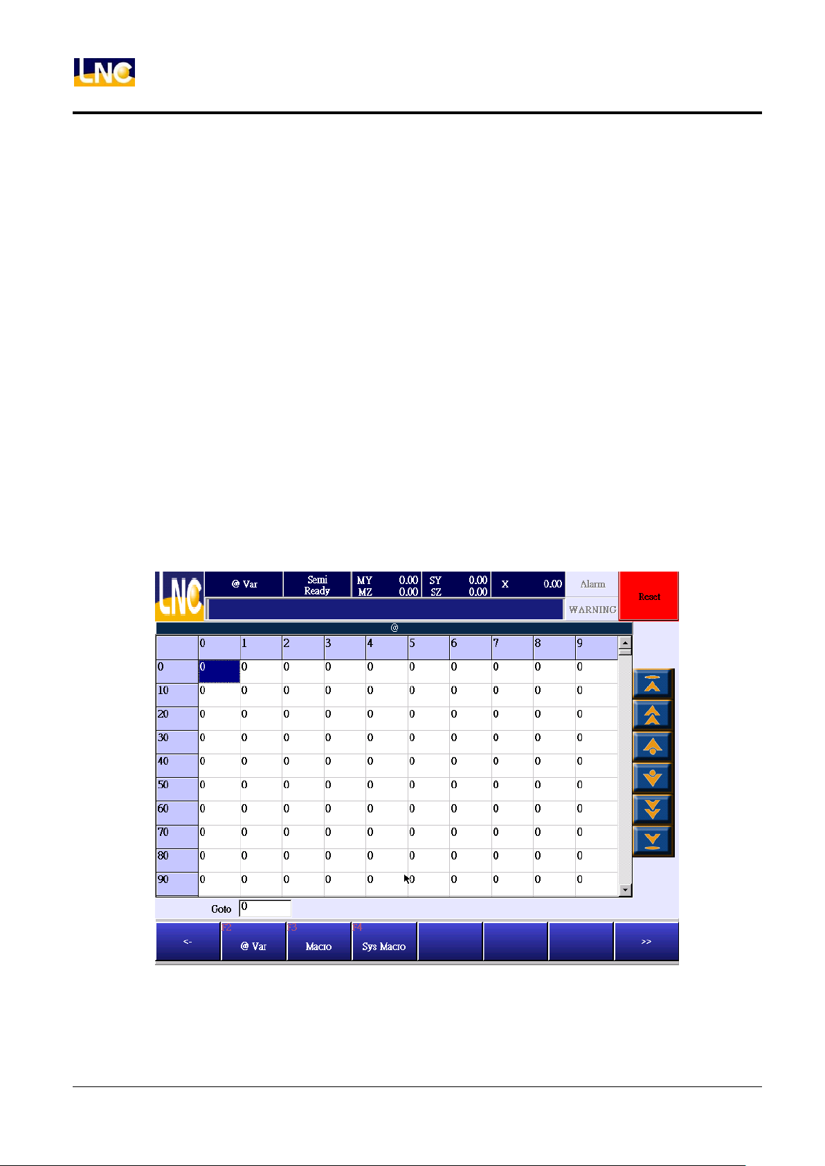
5.7 @Variables
Show mutual variable for main program and sub program.
46
LNC Technology Co., Ltd.
Page 55
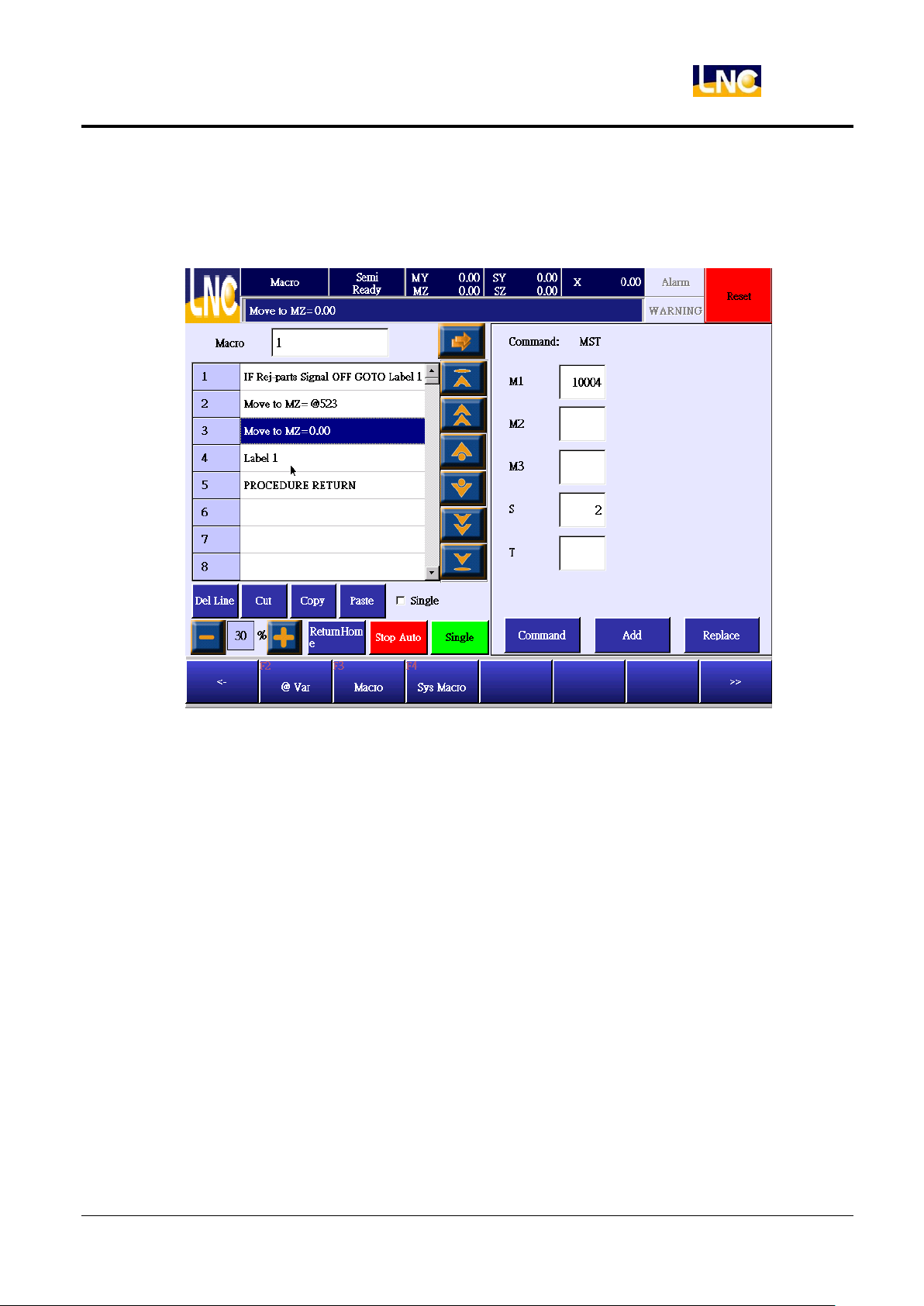
5.8 MACRO
Show MACRO as below.
LNC-R6000
Teach
Notice
1. If you want to edit MACRO, you will need to switch to machine maker level (10~19).
2. System offers 100 groups of MACRO to edit.
3. MACRO file name can accept 0~99, the MACRO here is for teach mode to call.
MACRO command editing description
MACRO editing is the same to teach program command, refer to chapter 5. Teach.
47
LNC Technology Co., Ltd.
Page 56
LNC-R6000
Parameter
6 Parameter
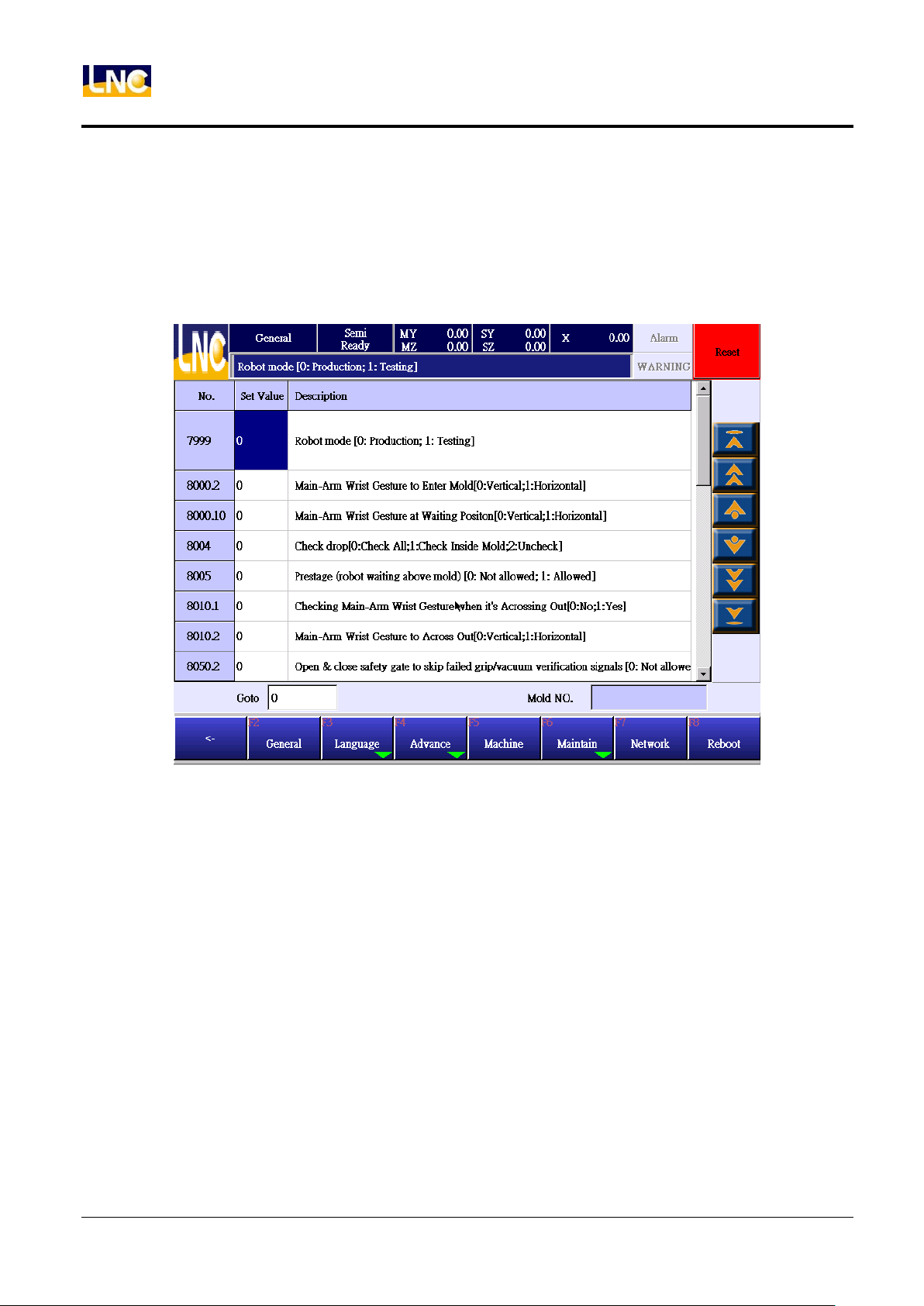
6.1 General parameter
This is the paramter list for general end-user, you can click setting value column to see keypad to do setting.
Detail general parameters, refer to chapter 10.
48
LNC Technology Co., Ltd.
Page 57
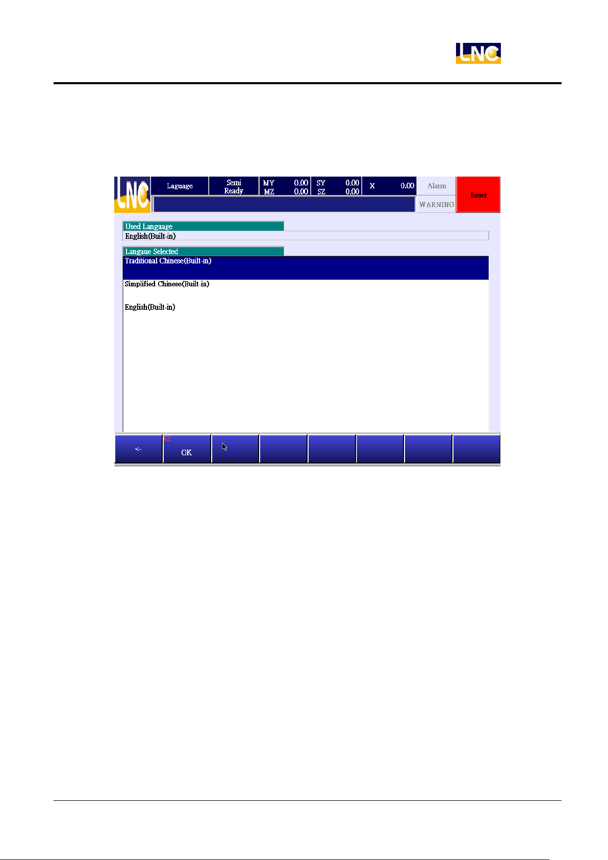
6.2 Language
Choose the language you want to use and press OK.
LNC-R6000
Parameter
49
LNC Technology Co., Ltd.
Page 58
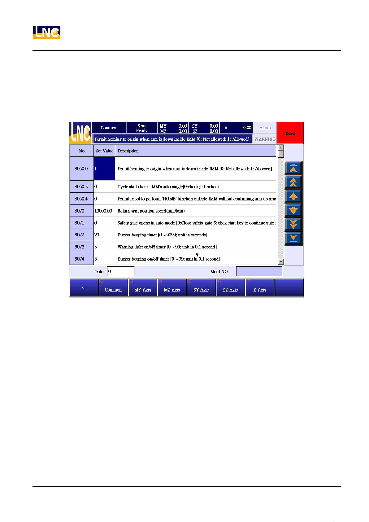
LNC-R6000
Parameter
6.3 Common parameter
This is the common parameter for machine makers, if you want to change this value, you will need to change to
10-19 level. You can click setting value column to see keypad to do setting. Detail general parameters, refer to
chapter 10.
50
LNC Technology Co., Ltd.
Page 59
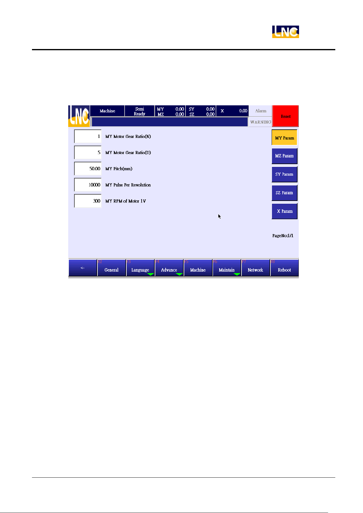
6.4 Machine parameter
This is to set up reducer gear ratio and motor parameters.
LNC-R6000
Parameter
1. Gear ratio(numerator): Set up gear ratio-numerator, if there is no reducer design, numerator and
denominator will be 1, EX : reducer=1:5, parameter=1.
2. Gear ratio(Denominator): Set up gear ratio- denominator, if there is no reducer design, numerator
and denominator will be 1, EX : reducer=1:5, parameter=1.
3. Pitch(mm):Most of the mechanical structure of the robot is through the motor and reducer to drive
gear. And gear through the belt to move machine mechanical structure. Distance of gear per 1
revolution = gear diameter X circumference ratio. In order to make this calculation easier, system will
time this circumference ratio automatically. Users only need to input gear diameter value.
※.If you use screw to move mechanical structure, not via gear and belt, you will need to input pitch
devide circumference ratio.
4. Motor 1 revolution pulse numbers:Motor corresponding rotation per revolution. The setting should
be relevant, then moving distance will be correct.
5. Motor 1 vollabele to rotation speed:motor’s max. rpm is corresponding to 10V, so make this value
to devide into 10, this is the value that we are going to set up.
51
LNC Technology Co., Ltd.
Page 60
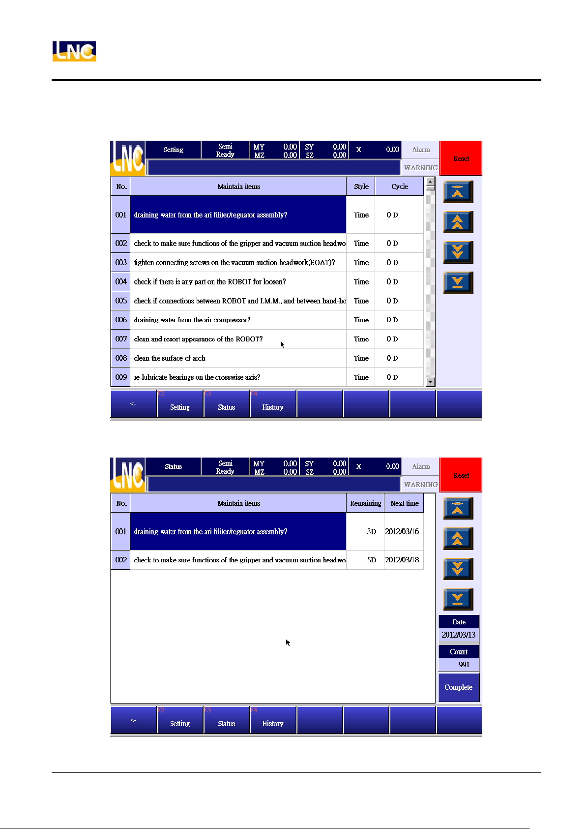
LNC-R6000
Parameter
6.5 Maintain
6.5.1 Maintain setting
6.5.2 Maintain status
52
LNC Technology Co., Ltd.
Page 61
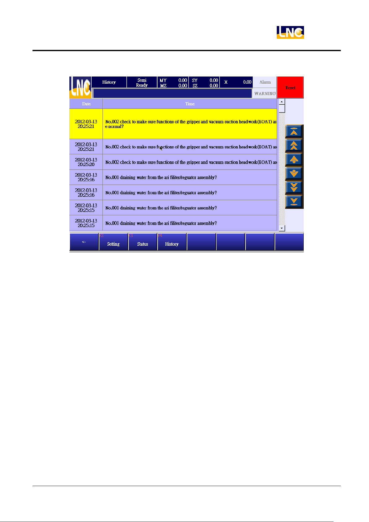
6.5.3 Maintain history
LNC-R6000
Parameter
53
LNC Technology Co., Ltd.
Page 62
LNC-R6000
Parameter
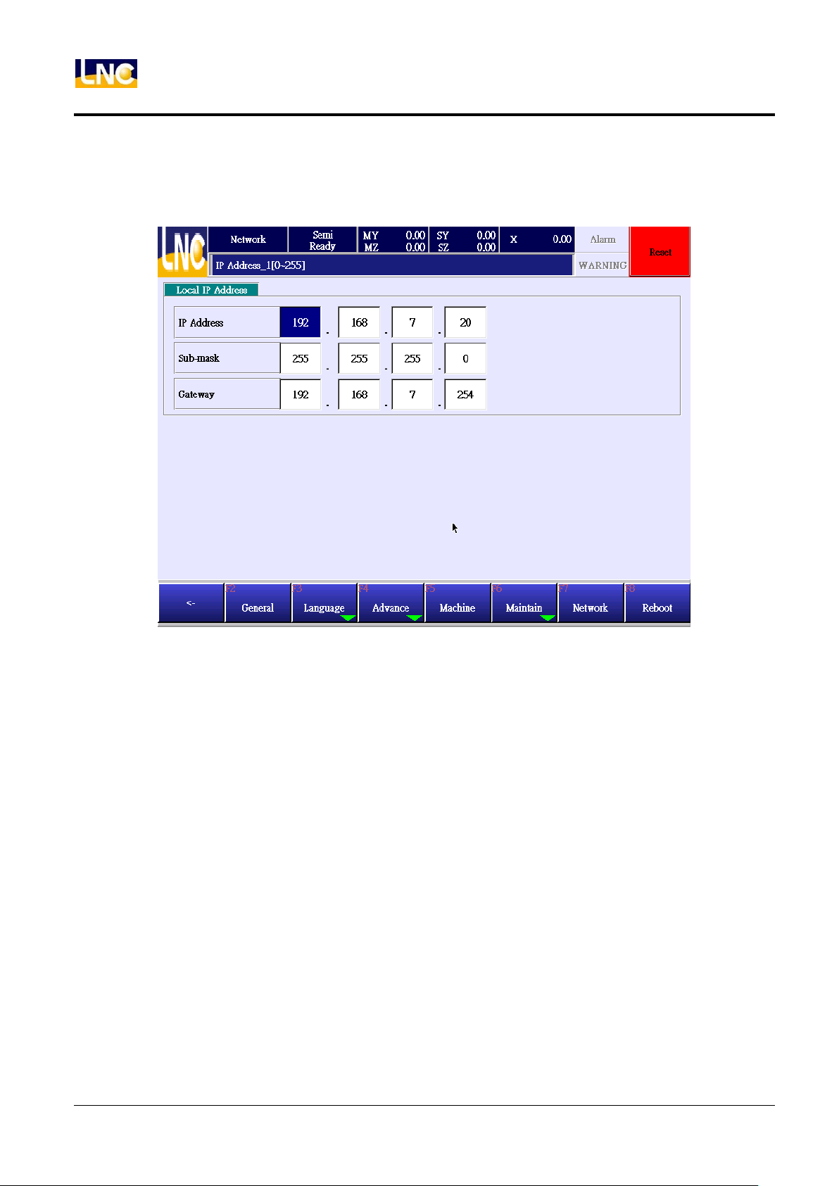
6.6 Network
How to set robot net address.
54
LNC Technology Co., Ltd.
Page 63
7 System
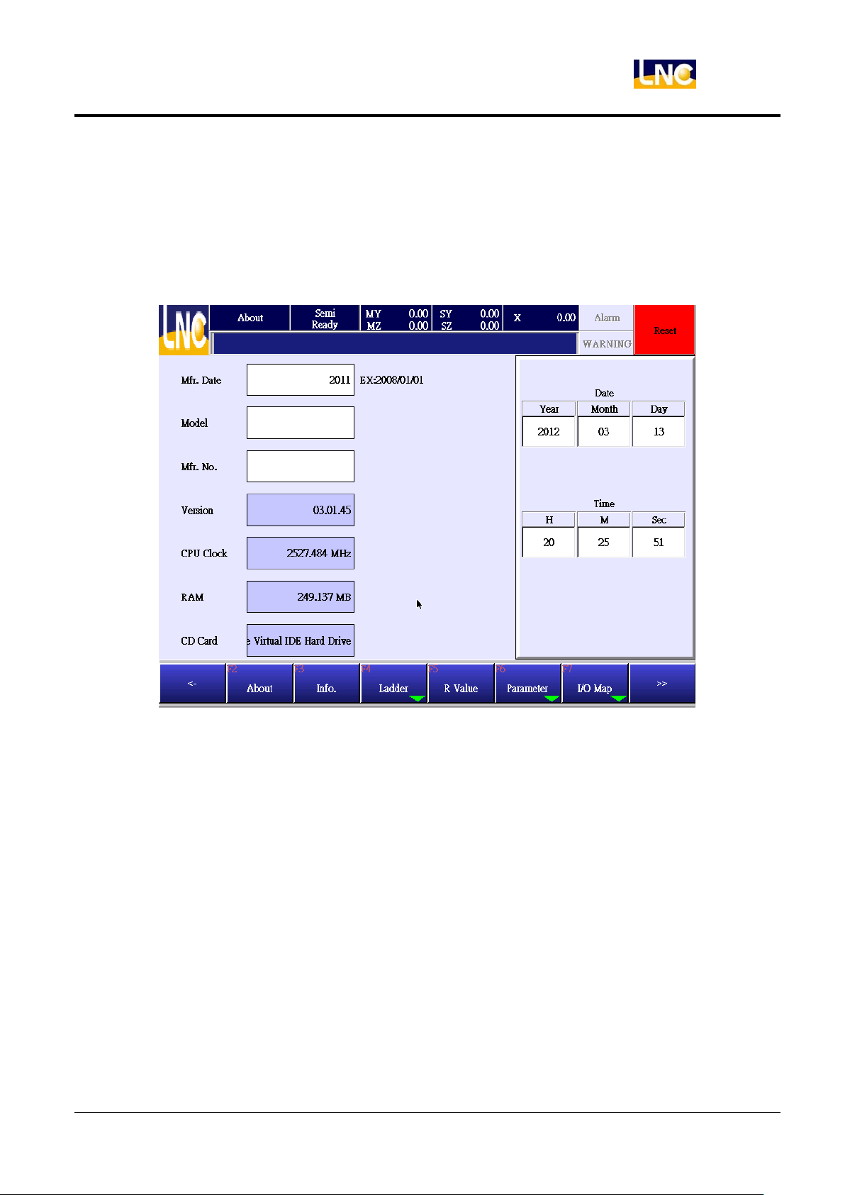
7.1 About
Show robot relating information.
LNC-R6000
System
55
LNC Technology Co., Ltd.
Page 64
LNC-R6000
System
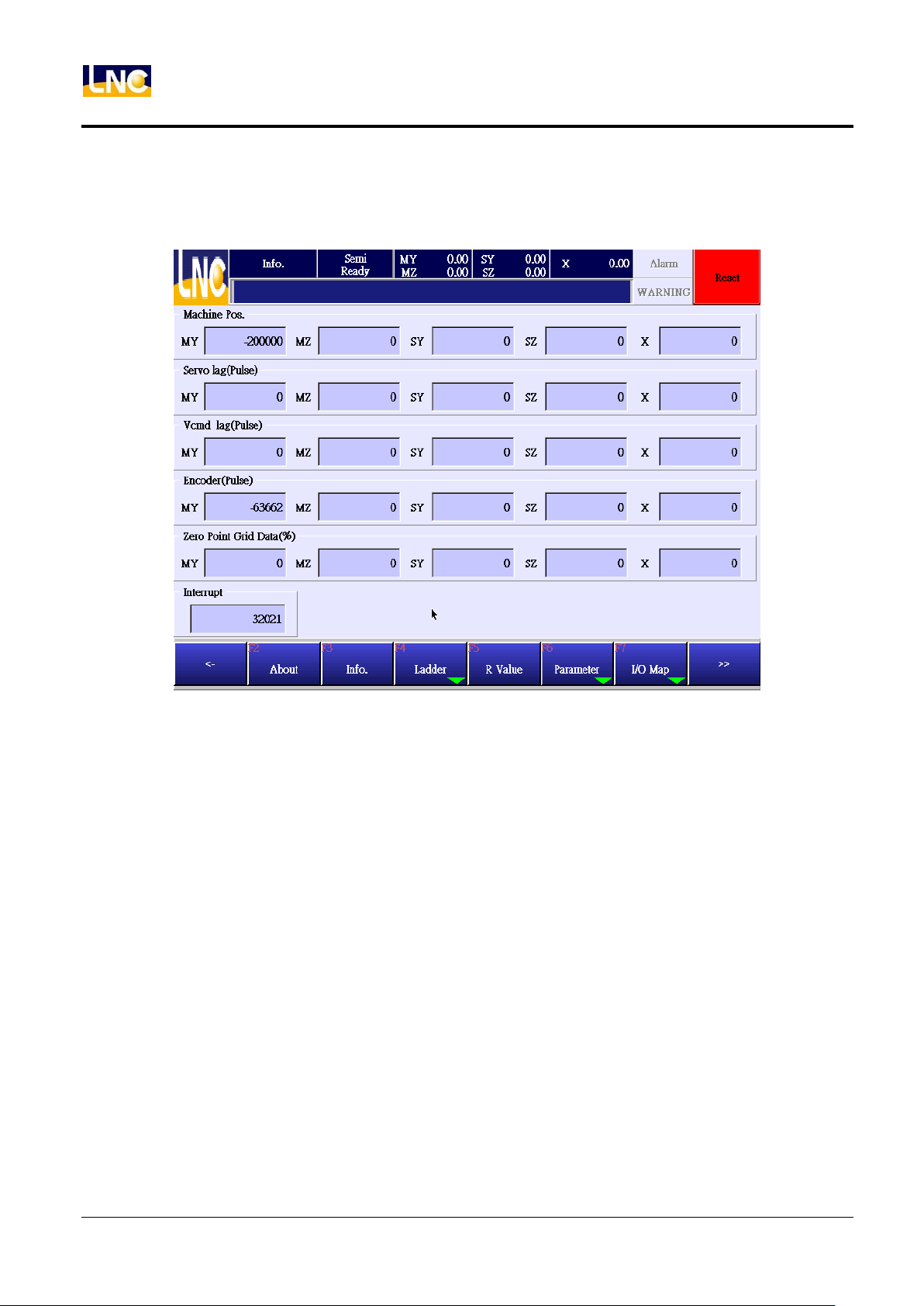
7.2 System info
Show system relaing info page.
1. Machine coordinate:Show current location machine coordinate, unit=um.
2. Servo lag(Pluse):Sending out movement command and exact feedback difference.
3. Vcmd servo lag(Pluse):Sending out movement command and exact feedback difference. When motor
use vollabele command, servo lag should refer to this column.
4. Encoder value:Current position’s corresponding encoder value.This value is encoder’s feedback value.
Machine zero’s encoder value should be 0.(only has small difference) When robot moves, encoder’s
value will change together. If you want to verify the accuracy of the machine, you can move back and
forth to check if the encoder value are the same.
5. Return home grid position(%):The percenlabele between the distance of Home dog signal trigger
location to motor Z axis signal and the distance of 1 motor revolution.
56
LNC Technology Co., Ltd.
Page 65
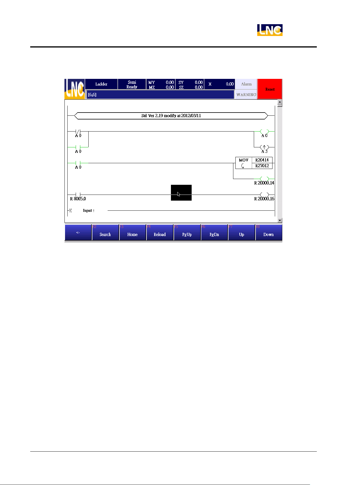
7.3 Ladder
LNC-R6000
System
57
LNC Technology Co., Ltd.
Page 66
LNC-R6000
System
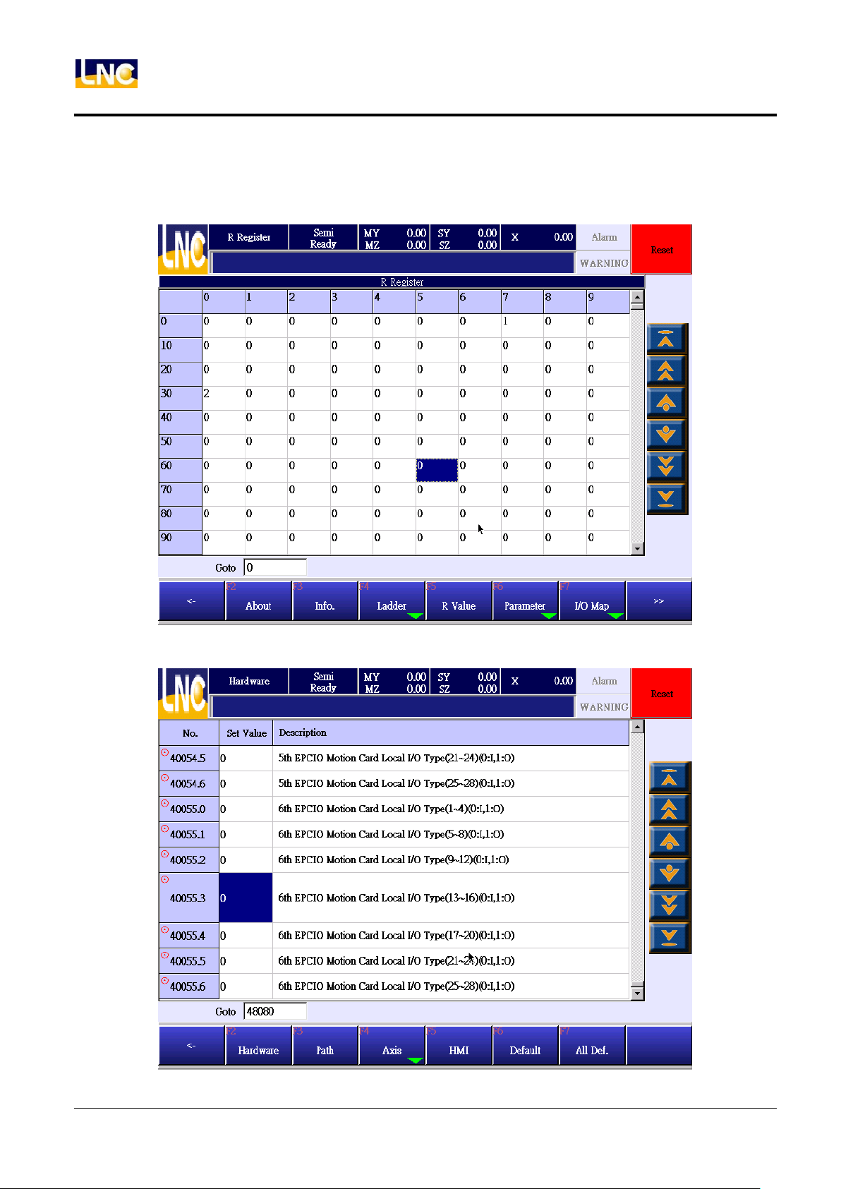
7.4 R bit
Show system register value.
7.5 System parameter
58
LNC Technology Co., Ltd.
Page 67
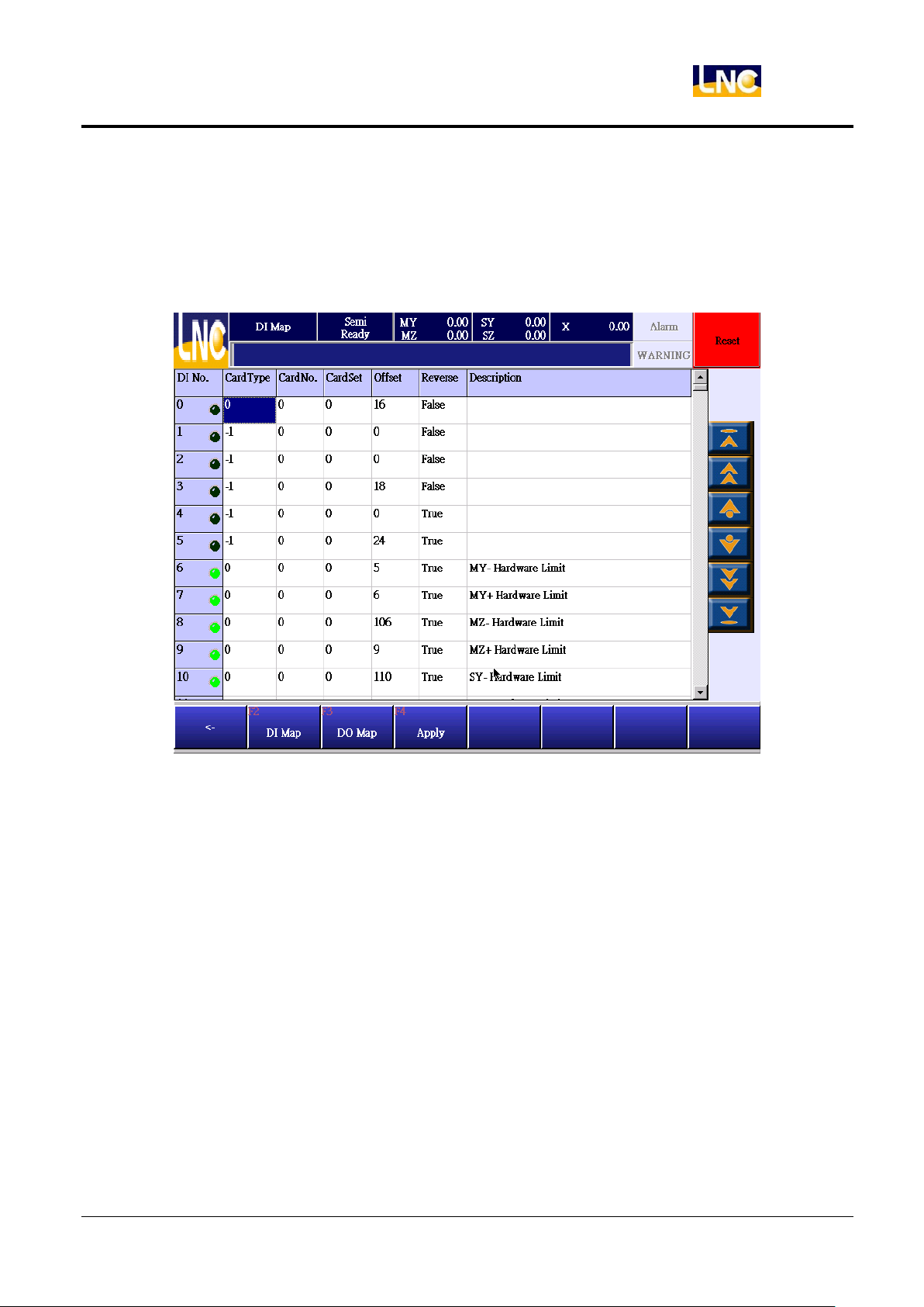
7.6 I/O Map
7.6.1 DI Map
Set up exact input and software input corresponding relationship.
LNC-R6000
System
59
LNC Technology Co., Ltd.
Page 68
LNC-R6000
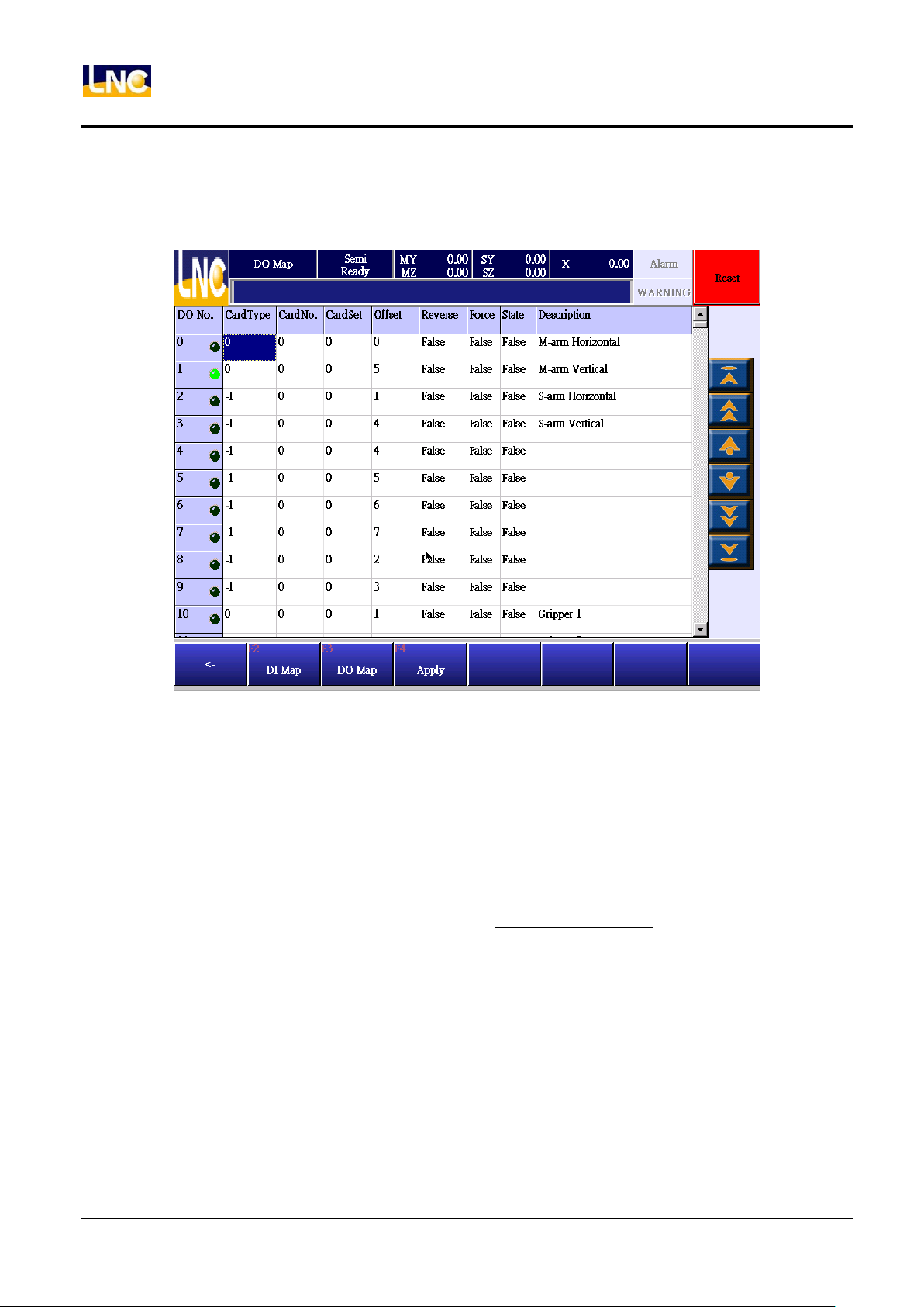
System
7.6.2 DO Map
Set up exact output and software output corresponding relationship
7.6.3 DI Map、DO Map setting
If you want to modify DI Map and DO Map, you need to have machine maker level or even bigger than this.
(10~19)
DI、DO mutual columns:
CardType:Show motion card type, current setting is 0, if -1=not in use.
CardNo:Show EPCIO card number, current setting is 0.
CardSet:1=Local IO;0=Remote IO, current robot did not use Local IO, therefore setting=0.
Offset:I/O to hardware location, connect EIO2000 to RIO1-15Pin HD-SUB female(robot project).Offset=0~191.
Reverse:True=make reverse of the signal or output. 0:False;1:True。
DO description:
Force:Whether to enforce the O point output, 0:False;1:True。
State:O point output status, 0:False(OFF); 1:True(ON)。
Offset description:
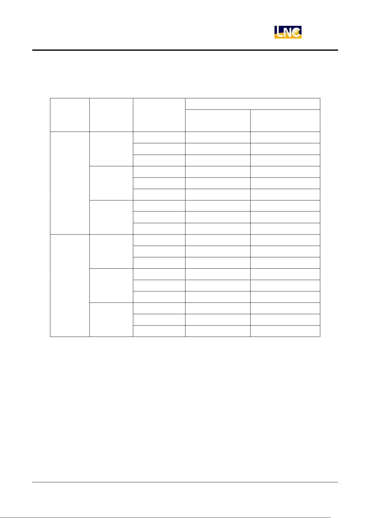
EIO2000 to RIO1 HD 15Pin D-SUB female, Offset is from 0. One set of EIO2000 can connect with 3 I/O card, 1
I/O has 20IN/16OUT, maximum is 3 cards, 60IN/48OUT. But here one EIO2000 need to be 64IN/64OUT, so
the second EIO2000 IO card offset is from 64, third EIO2000 Offset is from 128.
One set of EIO2000 can connect with 3 I/O card, 1 I/O has 20IN/16OUT, maximum is 3 cards, 60IN/48OUT. But
60
LNC Technology Co., Ltd.
Page 69
LNC-R6000
Motion card
position
EIO2000
Switch
setting
REL to
EIO2000
Offset
I
O
RIO1
S1 ON
I/O P1
0~19
0~15
I/O P2
20~39
16~31
I/O P3
40~59
32~47
S2 ON
I/O P1
64~83
64~79
I/O P2
84~103
80~95
I/O P3
104~123
96~111
S3 ON
I/O P1
128~147
128~143
I/O P2
148~167
144~159
I/O P3
168~187
160~175
RIO2
S1 ON
I/O P1
192~211
192~207
I/O P2
212~231
208~223
I/O P3
232~251
224~239
S2 ON
I/O P1
256~275
256~271
I/O P2
276~295
272~287
I/O P3
296~315
288~303
S3 ON
I/O P1
320~339
320~335
I/O P2
340~359
336~351
I/O P3
360~379
352~367
System
here one EIO2000 need to be 64IN/64OUT, so the second EIO2000 IO offset is from 256, the third EIO2000
Offset is from 320.
61
LNC Technology Co., Ltd.
Page 70
LNC-R6000
System
7.7 Backup
Run this function to do backup or restore machine paramter.
7.7.1 Parameter backup
Notice:
1. We recommend you to backup parameter files before using the controller, in case you want to restore to
the default status.
2. Currenly only support 4GB and below USB drive.
3. After backup, backup file will be saved at the backup directory.
4. There will have machine and ncfiles under this directory of backup, but sub program will be save outside of
ncfiles, other files will all be saved under machine directory.
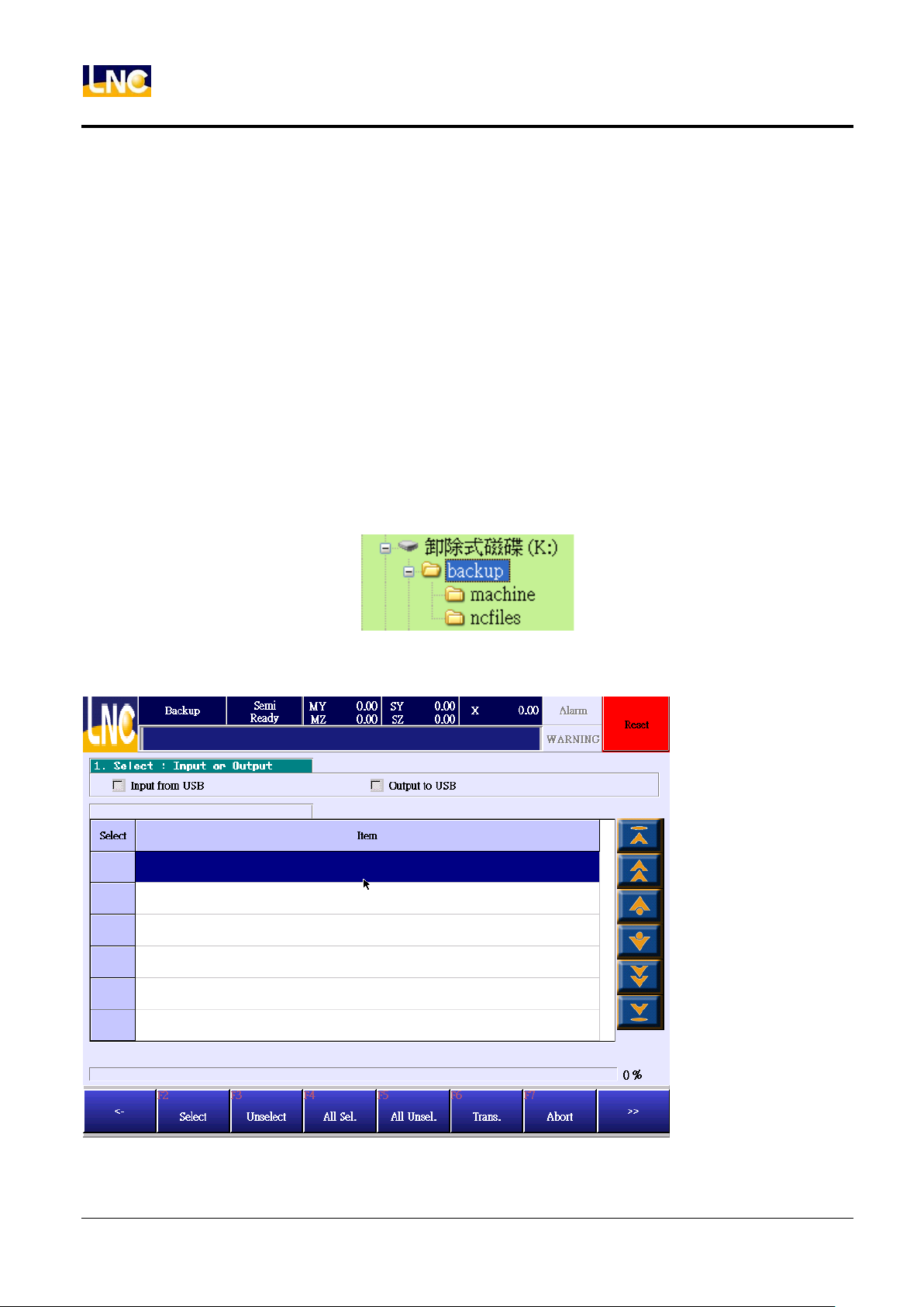
5. Backup directory tree as shown below.
Operation :
1. Go to【SYSTEM】, press【BACKUP】to see below.
2. Insert USB to controller.
62
LNC Technology Co., Ltd.
Page 71
LNC-R6000
System
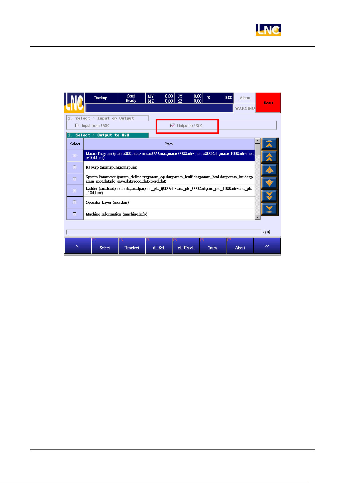
3. Click【output to USB】, if controller can not read this USB, there will be a message to show the USB insert
fail.That means controller did not accept this model’s USB;If the loading is success, you will see details as
below.
4. Select the file you want to backup, use F2~F5 or choose directly on the page, the file that you chose will be
download. You can click again to cancel selection.
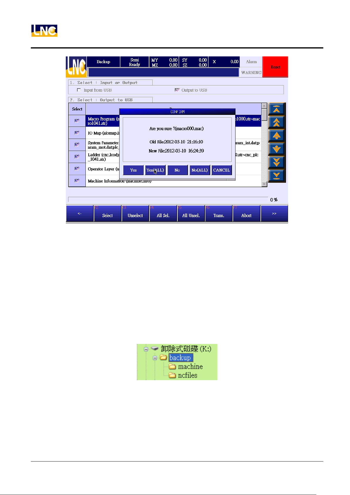
5. After selection, press【F6 to start downloading】. If you want to cancel the downloading, you can press【F7
cancel downloading】. We recommand you not to do this while downloading in order to ensure the integrity of
the backup data.
6. If there is previous backup file in this USB, system will ask if you want to rewrite current file, we recommend
you to press【yes to all】to make the integrity of the backup data.
63
LNC Technology Co., Ltd.
Page 72
System
LNC-R6000
7.7.2 Parameter restore
Notice:
1. After the modification results in the machine parameter error, you can restore previous parameter backup to
return to default setting.
2. Currenly only support 4GB and below USB drive.
3. Before running parameter restore, you should put backup file to backup directory of USB.
4. There will have machine and ncfiles under this directory of backup, but sub program will be save outside of
ncfiles, other files will all be saved under machine directory
5. Backup directory tree as shown below.
64
LNC Technology Co., Ltd.
Page 73
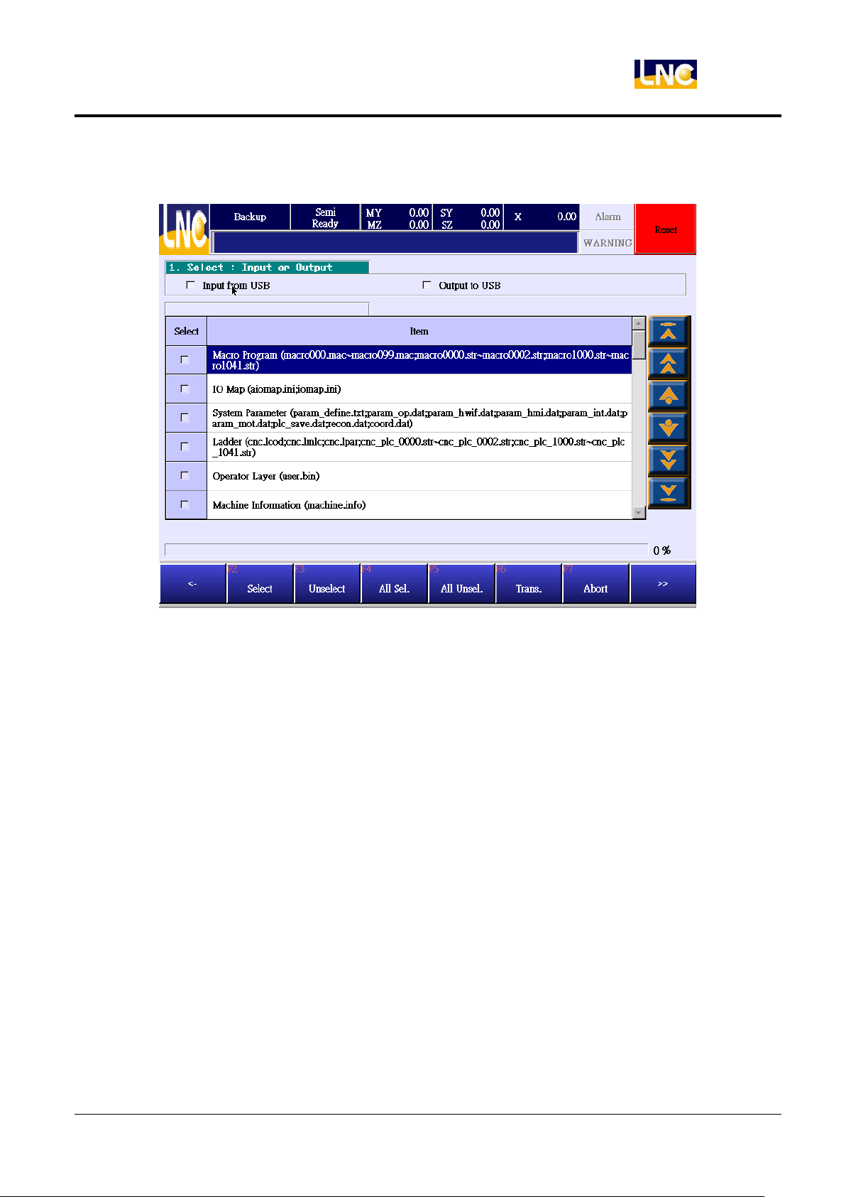
Operation:
1. Go to【SYSTEM】, press【BACKUP】to see below
LNC-R6000
System
65
LNC Technology Co., Ltd.
Page 74
LNC-R6000
System
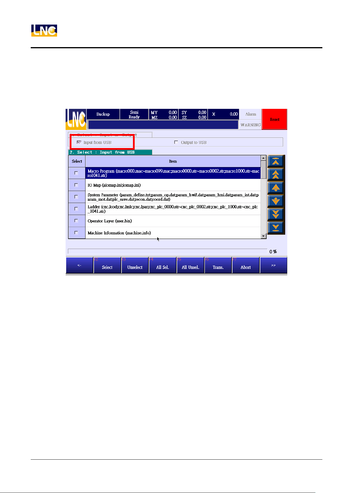
2. Insert USB to controller.
3. Click【input from USB】, if controller can not read this USB, there will be a message to show the USB insert
fail. That means controller did not accept this model’s USB;If the loading is success, you will see details as
below.
66
LNC Technology Co., Ltd.
Page 75
LNC-R6000
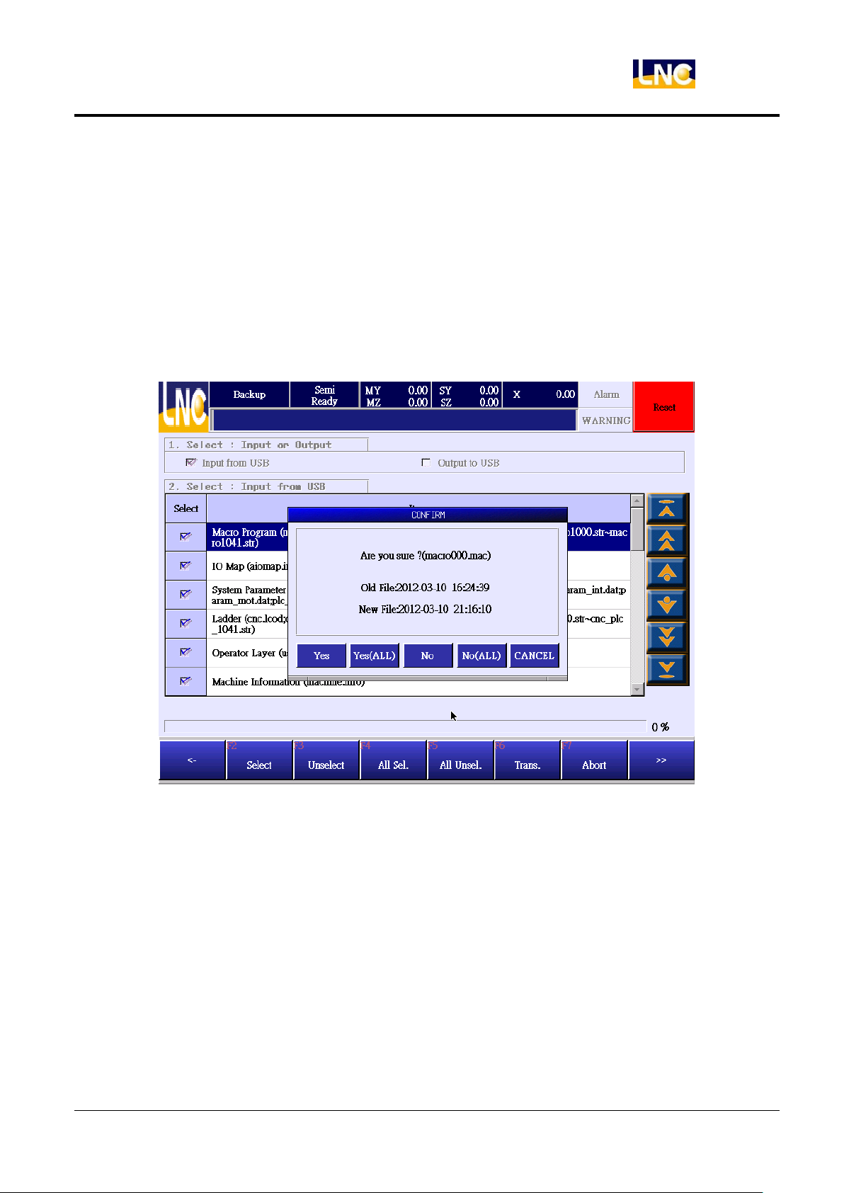
System
4. Select the file you want to upload, use F2~F5 or choose directly on the page, the file that you chose will be
upload. You can click again to cancel selection.。
5. After selection, press【F6 to start uploading】. If you want to cancel the uploading, you can press【F7 cancel
uploading】. We recommand you not to do this while uploading in order to ensure the integrity of the backup
data.
6. If there is previous backup file in this controller, system will ask if you want to rewrite old file, we recommend
you to press【yes to all】to make the integrity of the backup data.
67
LNC Technology Co., Ltd.
Page 76
LNC-R6000
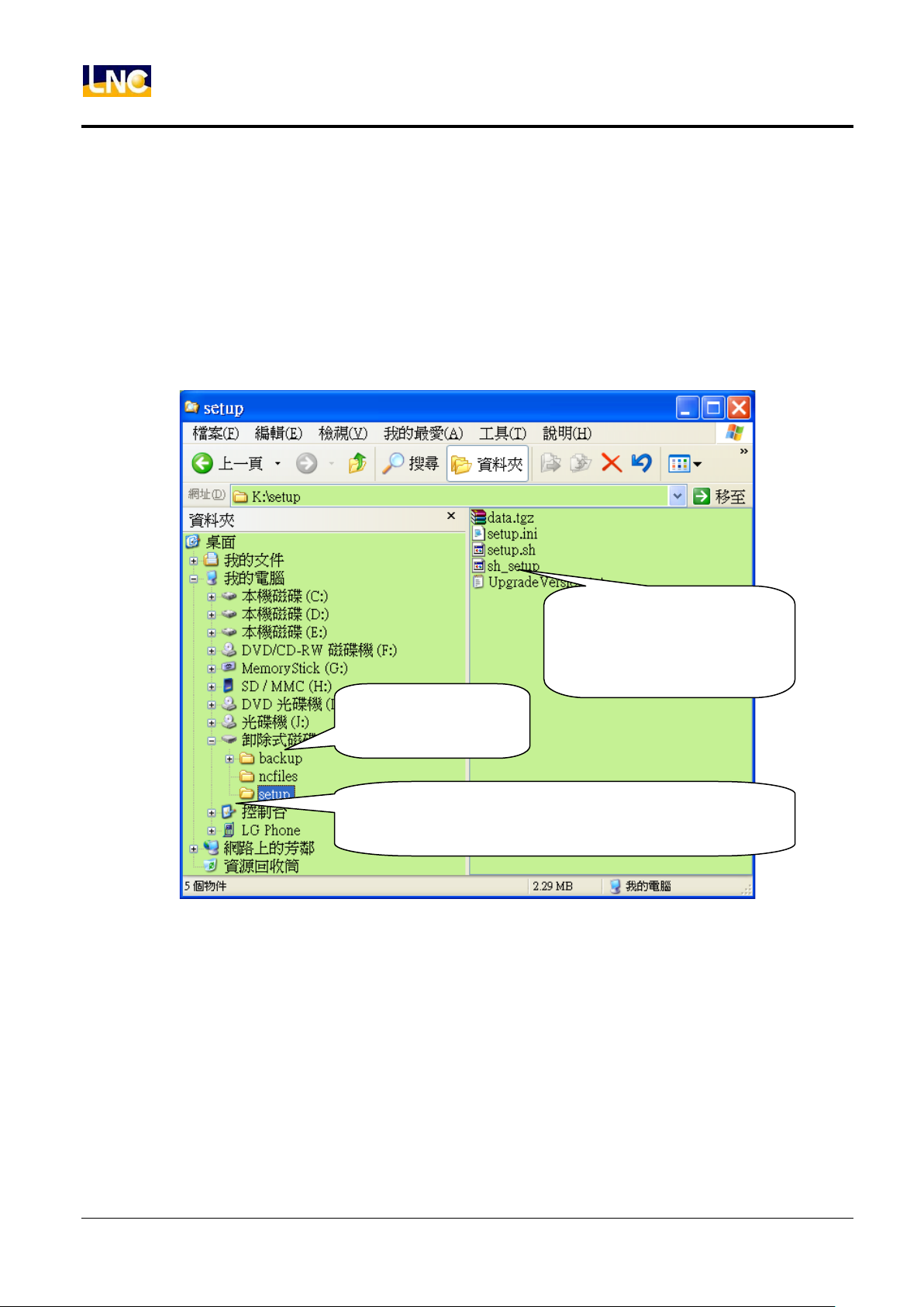
USB to computer
(new disk)
※ Upgrade directory form system provider, must be setup
in lower case.
Update file should be as picture,
but may increase or decrease
due to evolution of version.
System
7.8 Upgrade
You may need to have upgrade when the current operating system has error or this system has new
software functions.
Notice:
1. Currenly only support 4GB and below USB drive.
2. Save the new upgrade file from system provider into USB setup directory, such as below.
68
LNC Technology Co., Ltd.
Page 77
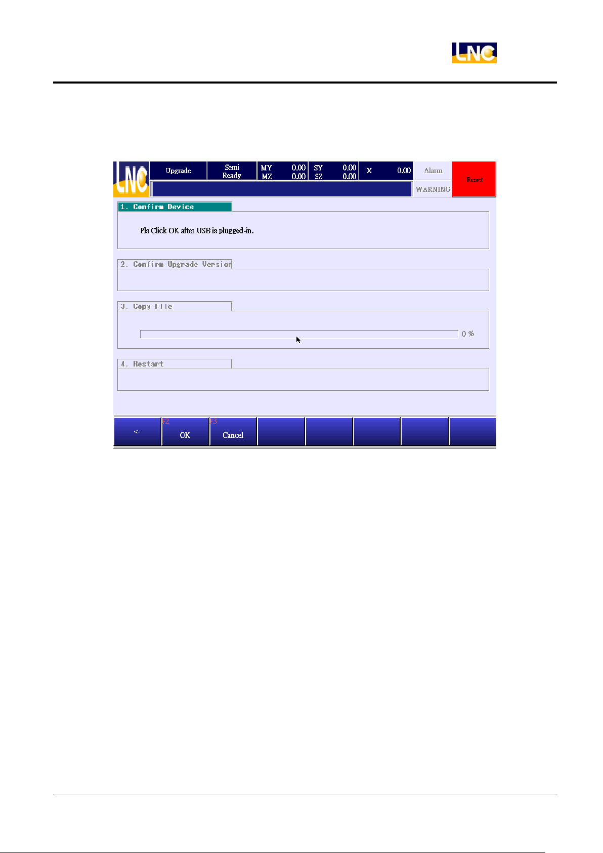
Operation :
1. Go to【SYSTEM】, press【UPGRADE】to see below.
LNC-R6000
System
2. Insert the USB with upgrade file into controller.
3. Press【F2 OK】, if controller can not read this USB, there will be a message to show the USB insert fail. If the
loading is ok, system will show upgrade file version number, you can check if the version number is correct
before loading.
69
LNC Technology Co., Ltd.
Page 78
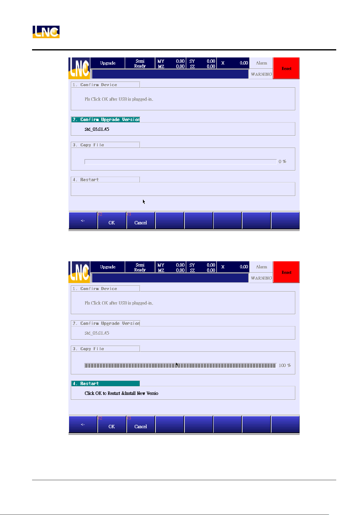
System
LNC-R6000
4. After confirming, press【F2 OK】,system will copy the upgrade file into controller data buffer area. After copy,
you will need to press EMG button first and reboot the system.
5. You will need to reboot after upgrading, then the upgrade is complete.
6. While upgrading, you can press【F3 cancek】to cancel before rebooting.
70
LNC Technology Co., Ltd.
Page 79
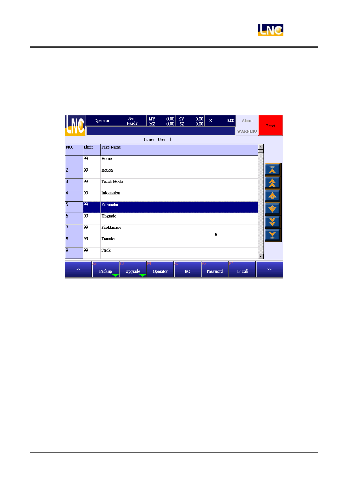
LNC-R6000
System
7.9 Operator authority
Set up authority for different users with different operation functions. Level 13 users can see level 13~29 and 99
operation page, but can not see higher level 12 page.
71
LNC Technology Co., Ltd.
Page 80
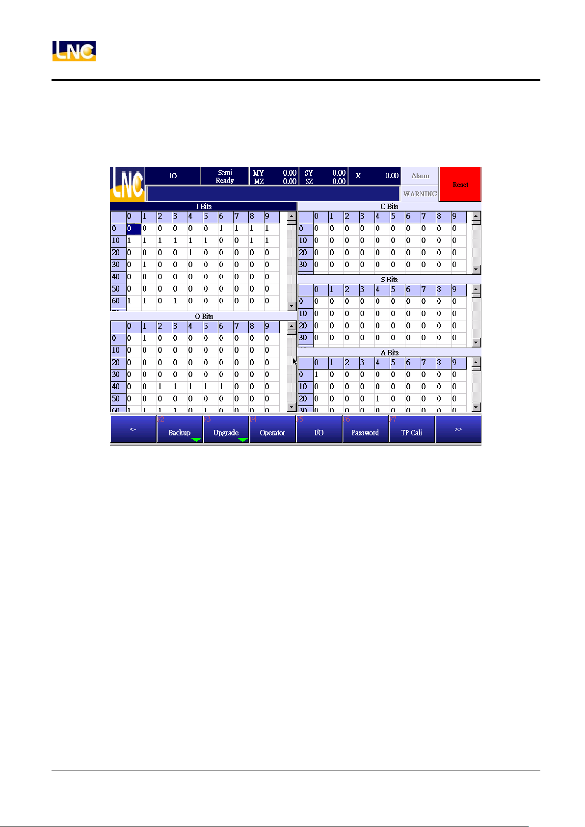
LNC-R6000
System
7.10 I/O
Show current system I、O、C、S、A status.
72
LNC Technology Co., Ltd.
Page 81
LNC-R6000
System
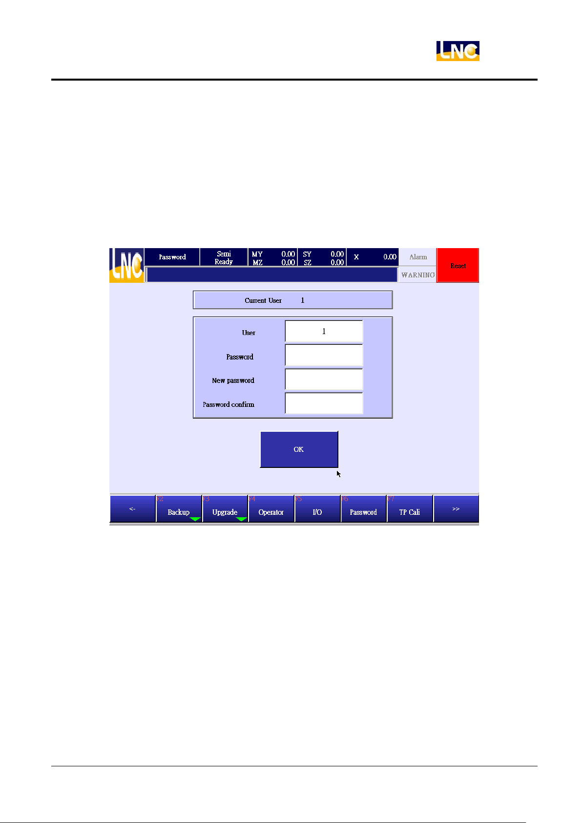
7.11 Change password
Notice:
Here you can only change current user’s password. If you want to change user user level, refer to user change
chapter.
Description:
Go to【MAINTAIN】, press【PASSWORD】to see below.
1. Here can only show current user level, you can not do any change here.
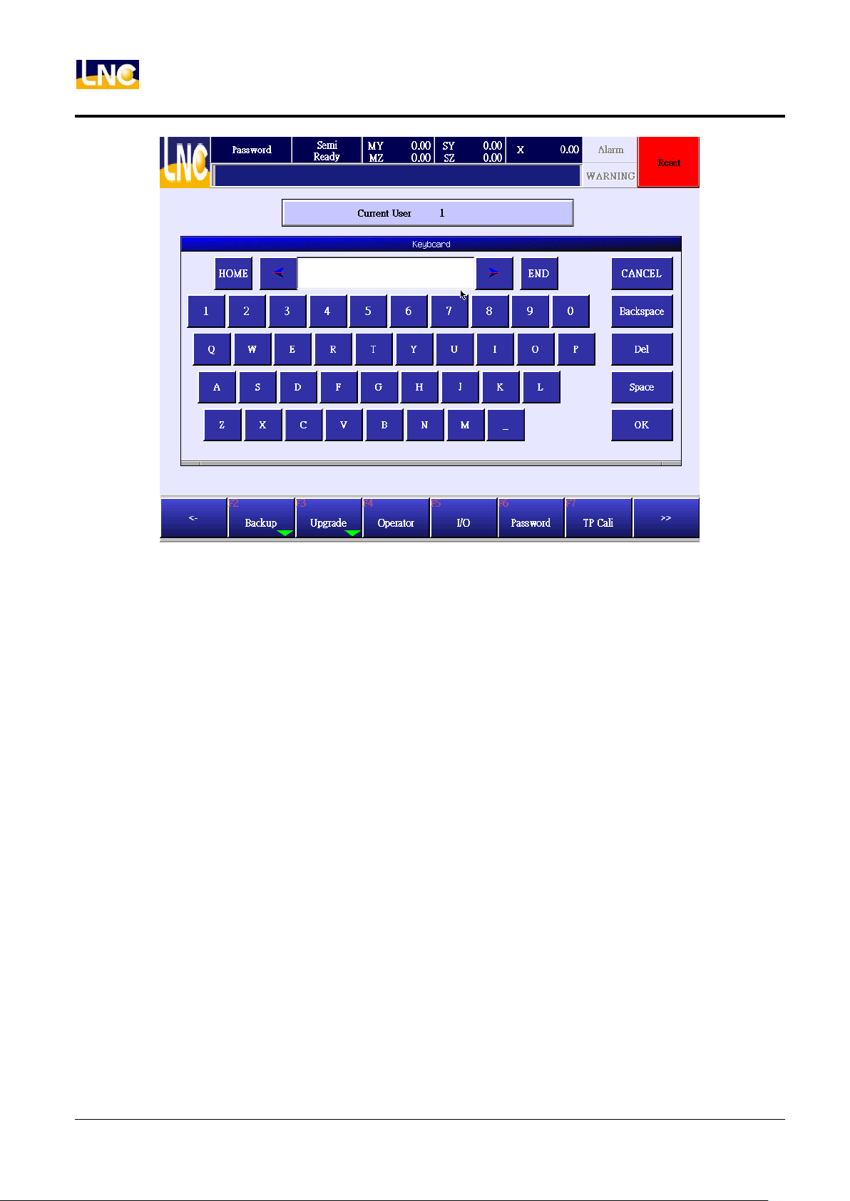
2. Then input current password, new password and confirm again new passwordd. Password will be shown as
*.
73
LNC Technology Co., Ltd.
Page 82
System
LNC-R6000
3. Password must be your current one.
4. New password and confirm password should be the same. If there are different, the setting will be fail.
74
LNC Technology Co., Ltd.
Page 83
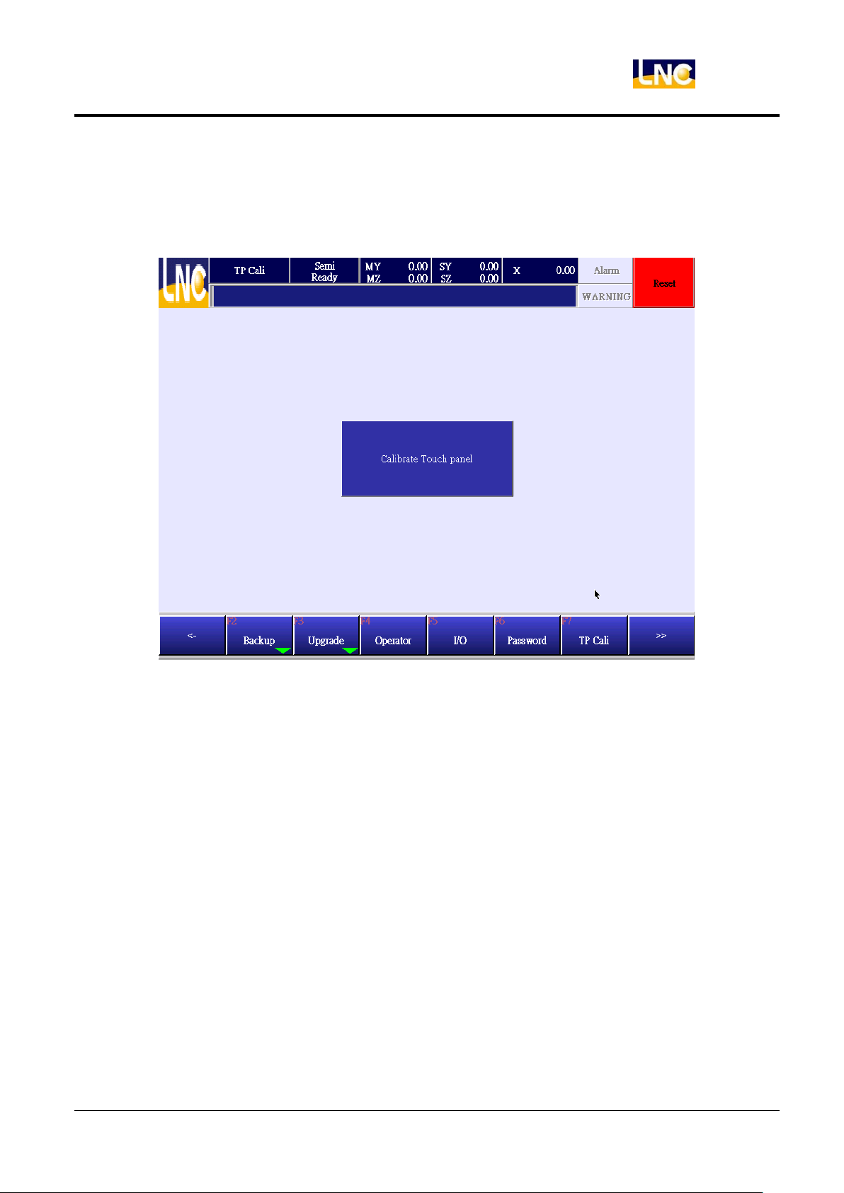
7.12 Monitor tuning
When monitor touching is not precise, you can use this function to do tuning.
1. This function only support to system provider, press monitor tuning to continue.
LNC-R6000
System
2. Press Reset, and power off to reboot.
75
LNC Technology Co., Ltd.
Page 84
System
LNC-R6000
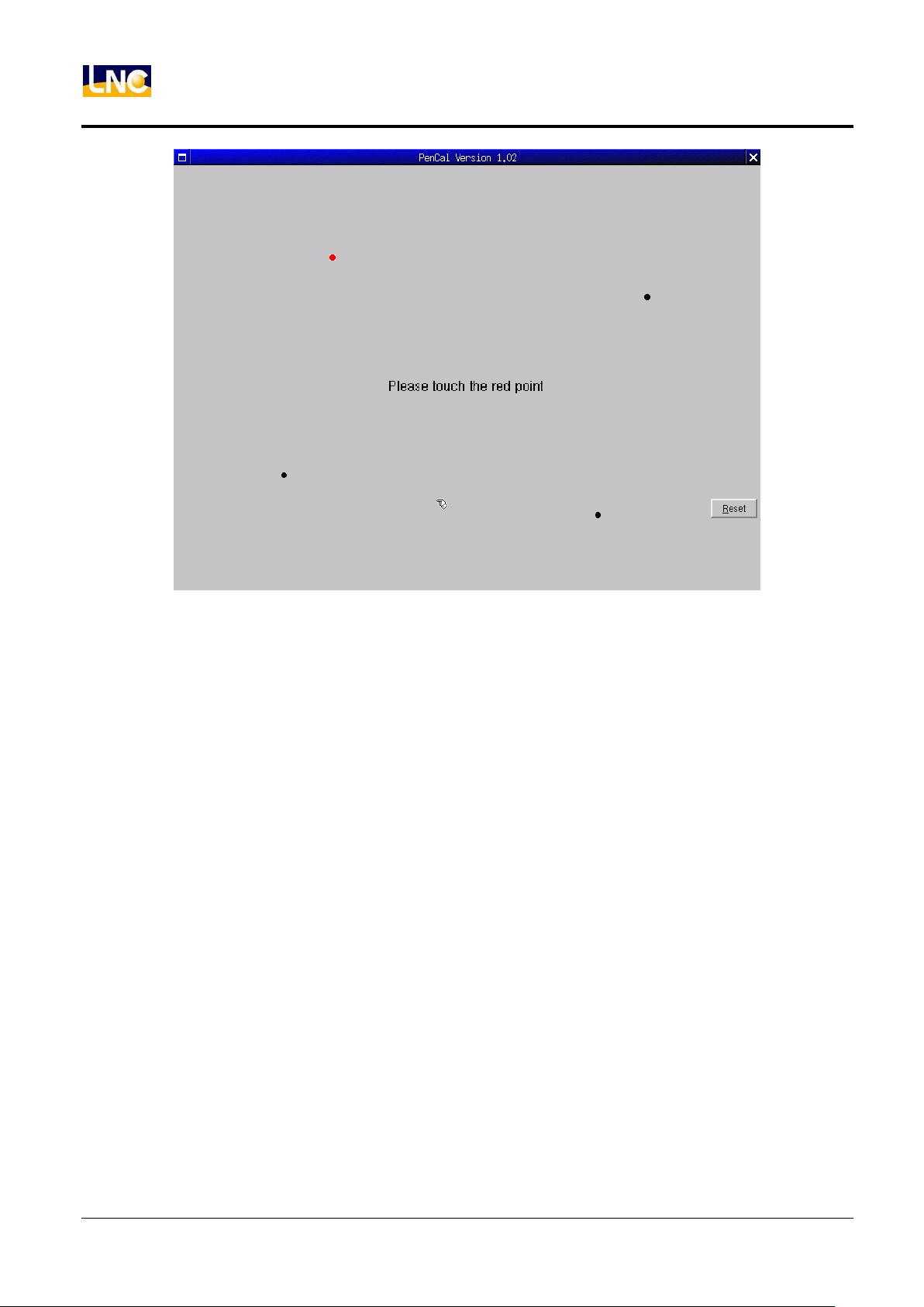
3. After rebooting, if the touch is still not precise, you can go to tuning page to retune again. At this time, you
can use tough pen to touch the little red point, after touch these 4 points in order, power off and reboot again.
76
LNC Technology Co., Ltd.
Page 85
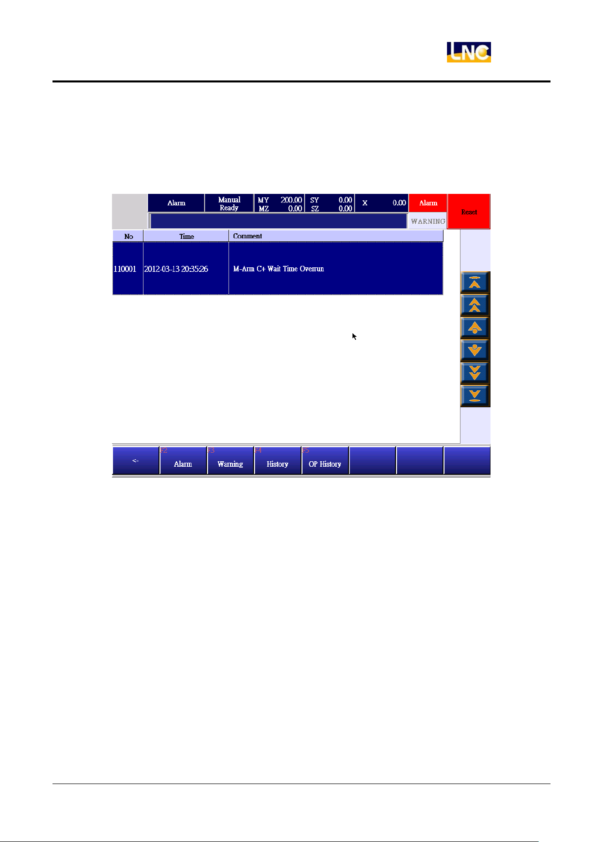
8 Alarm record
8.1 Alarm
Show current alarm content.
LNC-R6000
Alarm record
77
LNC Technology Co., Ltd.
Page 86
LNC-R6000
Alarm record
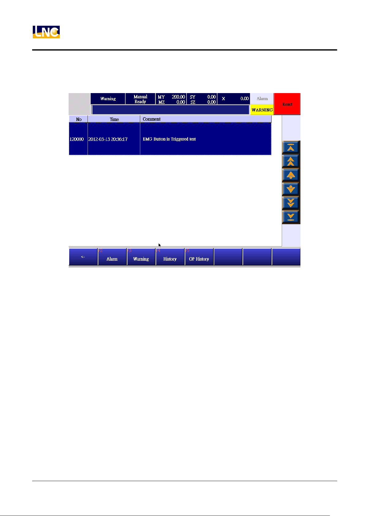
8.2 Warning
Show current warning content.
78
LNC Technology Co., Ltd.
Page 87
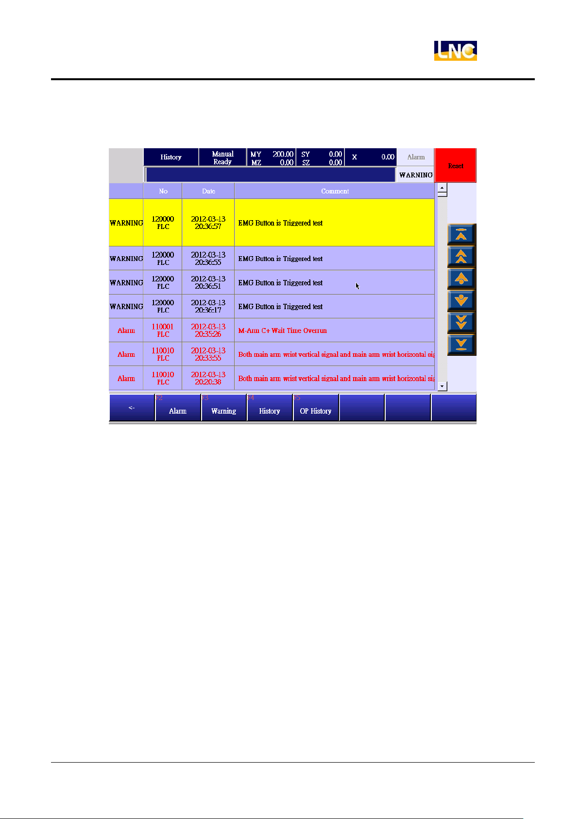
8.3 Alarm/warning history
Show record of alarm and warning.
LNC-R6000
Alarm record
79
LNC Technology Co., Ltd.
Page 88
LNC-R6000
Alarm record
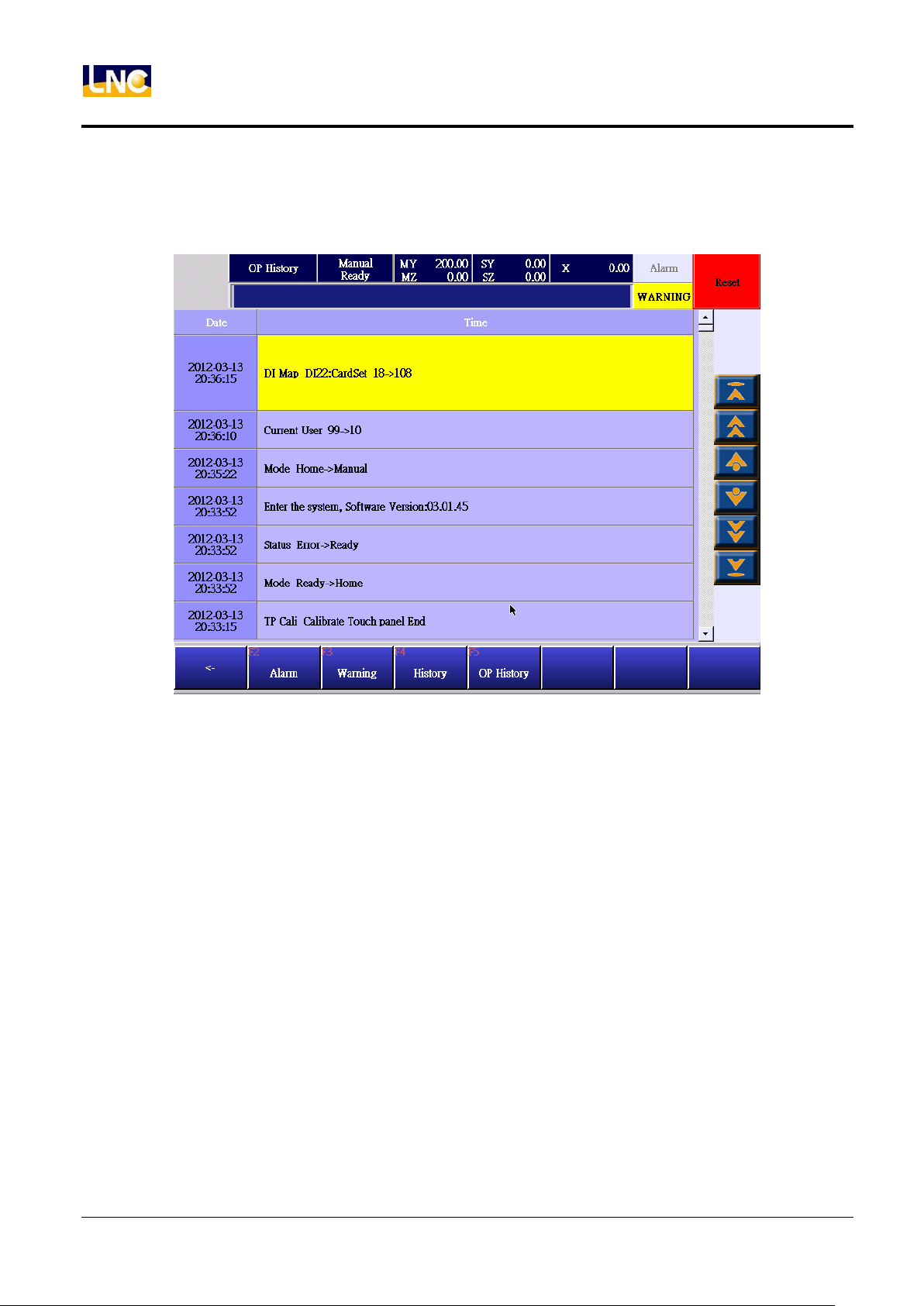
8.4 Operation history
Show operator’s total record.
80
LNC Technology Co., Ltd.
Page 89
LNC-R6000
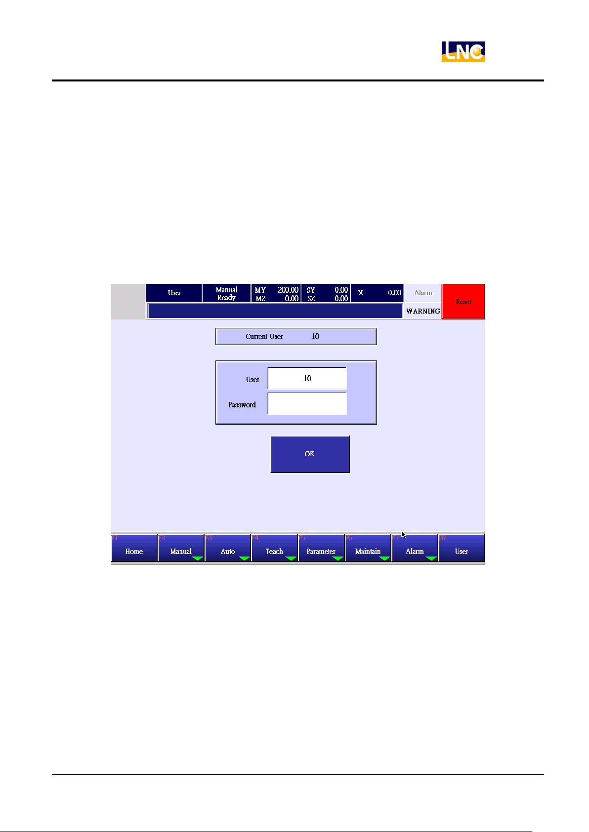
Switch users
9 Switch users
1. If end-user wants to edit program, he needs to change level to 20~29.
2. If machine maker wants to do maintenance, he needs to change to 10~19.
3. User 99 can only open file and do processing.
4. Default level is 99.
5. Every users can have his own password, password setting method refer to MANTAIN>CHANGE
PASSWORD chatper.
Level should be as below
User 0~9:System provider
User 10~19:Machine maker, default password=1111.
User 20~29:End-user, but can edit program file, default password=2222.
User 99:can only open file and do processing, no need to use password here, only need to input user and press
OK.
81
LNC Technology Co., Ltd.
Page 90

LNC-R6000
Parameter
10 Parameter
10.1 General parameter
Parameter 7999 running mode[0:General;1:trial]
Range :0~1。
0 :under auto mode, open mold should have OFFON signal, then arm will go down to pick goods.
1 :under auto mode, open mold only have ON signal, then arm will go down to pick goods. This is for tuning
mode.
Tuning mode as below :
a. Open mold only have ON signal, robot can run, no need to have upper side trigger.
b. Ignore I/Ostep delay time.
c. When system reboot or return home, this parameter will return to 0.
Parameter 8000.2 the main arm posture when going into mold[0:vertical;1:horizontal]
Range :0~1。
Check if the posture is not corresponding to setting when going into mold, trigger alarm.
0:The posture to go into mold should be vertical.
1:The posture to go into mold should be horizontal.
Parameter 8000.10 main arm posture when standby[0:vertical;1:horizontal]
a. The rotating posture when main arm return to standby point.
b. If posture is not the same with parameter, stop processing.
Parameter 8004 parts drop check while moving [0:check for whole travel;1:check in mold 2:not check]
Range :0~2。
Check timing for drop parts while picking goods with vacuumer/gripper.
0(Check for whole travel): continue checking when picking to placing.
1(Check in mold): only chek while X axis in mold area.
2(Not check): do no check if goods drop.
Parameter 8005 standby vertically[0:N/A;1:Yes]
If vertical stanby.
0 :N/A
Main arm:limit location is the max. distance to go down in mold『(P8): MZ axis to go in/out safety height』
Sub arm:limit location is the max. distance to go down in mold『(P8): SZ axis to go in/out safety height』
1:Yes
Main arm:limit location is the max. distance to go down in mold『(P4): the height of MZ axis to close mold safely』
Sub arm:limit location is the max. distance to go down in mold『(P4): the height of SZ axis to close mold safely』
Parameter 8010.1 check main arm posture when going out [0:Not check;1:check]
Range :0~1。
In order to check the program, you can set up parameter to check if moving posture correct or not while X axis in
mold.
0:do not check。
82
LNC Technology Co., Ltd.
Page 91

LNC-R6000
Parameter
1:check if correct, refer to parameter 8010.2 to see posture setting( vertical, horizontal).
Parameter 8010.2 check main arm posture when going out [0:vertical;1:horizontal]
Range :0~1。
Check if moving posture correct or not while X axis in mold. This only valid when parameter 8010.1=1
0:vertical
1:horizontal
Parameter 8050.2 safety door status when vacuumer/gripper takes fail[0:N/A;1:close door and continue]
When vacuumer/gripper takes fail, it will trigger warning and stop machine. Under general situation, users need
to press [cycle start] to run again. In order to speed up processing, users can close safety door one time, this
action is equivalent to pressing the[cycle start] button.
Parameter 8050.6 middle plate[0:Yes;1:N/A]
a. When machine do not use middle plate function, make parameter to be『1:N/A』
b. When using middle plate function, check below info and run.
If wiring correct.
If DI Map setting correct.
Parameter 20001.2 not using robot[0:N;1:Y]
Range :0~1.
If output not using robot signal.
0:N
1 :Y
Parameter 48401 monitor sleep time setting[unit:minute]
Range :0~999。
When monitor is not under operation, go to sleep mode.
0:N/A
1~999 :delay time setting
10.2 Common parameterMutual parameter
Parameter 8050.0 in mold, Z axis in mold to return to standby point[0:N/A;1:Yes]
Range :0~1
Return standby point function is easy, but when robot is going down in mold, it has risk to scratch mold, so default
setting is that you can not return to standby. You need to move the robot arm to certain safe height and then
return stanby point.
Below is the order to return standby point:
Arm location
In mold:pull axisvertical axisturninghorizonal axis.
No in mold:vertical axis turning pull axis horizonal axis.
Parameter 8050.3 run and check injection molding machine auto signal [0:check;1:not check]
If you run auto mode, you will need to check injection molding machine auto signal.
83
LNC Technology Co., Ltd.
Page 92

LNC-R6000
Parameter
Parameter 8050.3 run and check injection molding machine auto signal [0:check;1:not check]
Range :0~1。
This function is to set up the check system for injection molding machine auto signal and then robot to run auto
mode .
machine did not have auto signal, set up parameter= 1:Not check.
0:need to check
1:no need to check
Parameter 8050.4 out of mold, if z axis did not go to up limit, can not return to standby[0:N/A; 1:Yes]
Range :0~1。
Return standby point function is easy, but when robot is at safe area out of moldwhen robot goes down to pick
goods, it has risk to collide with other parts, so default setting is that you can not return to standby. You need to
move the robot arm to certain safe height and then return stanby point, set up parameter to be 1:Yes
Below is the order to return standby point:
Arm location
In mold:pull axisvertical axis turning horizonal axi
Not in mold:vertical axis turning pull axis horizonal axis
Parameter 8070 return standby point speed [unit:mm/Min]
Range :10~50000。
Press【return standby】, the speed for every axis to go to this point.
Parameter 8071 safe door status in auto mod[0:door close, press cycle start to continue;1:door close
and continue working;2:stop immediately]
Range :0~2
Under auto mode, open safety door, robot will...
0:door close, press cycle start to continue when opening safe door, alarm will stop immediately, when close
the door, you will need to press cyclestart to continue the next movement.
1:door close and continue working when opening safe door, alarm will stop immediately. But when closing
safety door, robot will continue to move later movement.
2:Stop immediatelywhen open safety door, alarm will stop immediately(the same to reset button), you will
need to return robot to stanbypoint and repress cyclestart button to continue.
※If there is customers who want to cancel this safety door function, you will need to emphasize the risk, if the
customer does not accept this, please recommend customer to short connect the safety door signal.
Parameter 8072 buzzer ring time[0~9999,unit:second]
Range :0~9999
If you think the buzzer is too noisy, you can set up the time for buzzer to shut down.
0:buzzer continued to do output, do not have auto shut down function.
Not 0 :for how many seconds, buzzer to shut down, until next alarm to ring.
Parameter 8073 alarm light flash interval time [0~99,unit:0.1second]
Range :0~99
The setting of alarm light flash interval time.
0:always on, if the alarm light has flash funtion, set up parameter=0.
Not 0 :for how many seconds, light to shut down or turn on period.
84
LNC Technology Co., Ltd.
Page 93

LNC-R6000
Parameter
Parameter 8074 buzzer flash interval time [0~99,unit:0.1second]
Range :0~99
The setting of buzzer to ring on and off interval time.
0:always on, if the buzzer has on and off funtion, set up parameter=0.
Not 0 :for how many seconds, buzzer to shut down or turn on period.
Parameter 9001.0 axis movement safety switch check setting [0:Not check;1:check]
Range :0~1。
When moveing axis manually, if need to check right side safety switch on teach pandent.
0:Not check。
1 :Check。
Parameter 9001.1 general O point safety switch check setting[0:Not check;1:check]
Range :0~1。
When manual output or close robot air cylinder, if need to check right side safety switch on teach pandent. Air
cylinder movement has vertical, horizontal, sub-arm.
0:Not check。
1 :Check。
Parameter 9001.2 vacuumer/gripper O point safety switch check setting[0:Not check;1:check]
Range :0~1。
When manual output or close vacuumer or gripper, if need to check right side safety switch on teach pandent.
0:Not check。
1 :Check。
Parameter 9001.3 peripheral devices O point safety switch check setting[0:Not check;1:check]
Range :0~1。
When manual output or close peripheral devices, if need to check right side safety switch on teach pandent
0:Not check。
1 :Check。
Parameter 9001.4 run/stop safety switch check setting [0:Not check;1:check]
Range :0~1。
When teach or auto mode run or stop, if need to check right side safety switch on teach pandent
0:Not check。
1 :Check。
Parameter 9030 robot I/O alarm delay time[unnit:minute]
Range :0~9.9。
When output vertical/horizonal/robot air cylinder movement, the corresponding input arrive signal did not trigger,
system will send alarm.
Recommand is 3 second.
Parameter 9037 Movable max.positon & offset of limit position in manual mode[unit:mm]
Range :0~100.00
0 :when moving manually, you can move to soft limit or restricted location to trigger soft limit warning.
Not cero value:when in manual movement, you can only move to soft limit or restricted location to minus
85
LNC Technology Co., Ltd.
Page 94

LNC-R6000
Parameter
arameter setting value, then this is the max.movable location to prevent trigger soft limit warning.
EX:the max movement positon of horizonal axis in mold is 100, min. is -20, offset is 5, then arm can move
between -15~95 to prevent trigger soft limit warning.
Parameter 9039 open mold complete, delay for how long to do down[unit:ms]
Range :0~10000(max.10 second)
System may receive open mold complete signal, but the injection molding machine still not opens up completely,
therefore you can set up ON delay time, then robot will go down in mold to prevent collision.
Parameter 48056 editable distance range under auto mode [unit:mm]
Range :0~999999.999
If you want to do position fine tune under auto mode, but you are afraid that the tuning value is too big to have
collision. You can set this parameter to define the range.
Parameter 48057 machine type[0:5 servo;1:3 servo]
Range :0~1
Set up machine type.
Parameter 48091 interval between main arm and sub-arm pull out axis after returning home[unit:mm]
Range :0~999999.999
This parameter is only valid for 5 servo axis robot.
The distance between main pull arm and sub pull arm after returning home and 2 pull out axis standby point
is cero.
If this parameter setting is too big may lead wrong range judgement to make main arm and sub-arm pull
arm to collide.
Parameter 48402 delay time when monitor sleep to wake [unit:second]
Range :0~999。
When monitor in sleep mode, you can touch monitor to wake it up, but there will be a delay time. You can set up
this parameter to define the delay. This delay can prevent wrong operation while monitor is still black,
recommend setting is 3 second.
Parameter 50012 arrive check range default[unit:mm]
Range :0~999999.999。
When point to point, range is smaller than parameter setting, you can run next command. If this parameter
setting is too small, the movement speed will be too slow, recommand setting is 30mm.
Parameter 60172 movement max. speed[unit:mm/Min]
Range :0.001~999999.999。
The max. movement speed( program speed is 100% and run speed is 100%). But the exact speed will need
torefer to exact stuation under auto mode(Parameter60214~60218).
10.3 Common parameterAxis parameter
Parameter 48011、48013、48015、48017、48019 xx axis soft limit(+)[unit:mm]
Range :-999999.999~999999.999。
After returning home, max. (+)distance that axis can move
86
LNC Technology Co., Ltd.
Page 95

LNC-R6000
Parameter
Parameter 48012、48014、48016、48018、48020 xx axis soft limit(-) [unit:mm]
Range :-999999.999~999999.999。
After returning home, max. (-)distance that axis can move
Parameter 48048~48052 xx axis max.speed manually[unit:mm/min]
Range :1000~200000。
When moving axis manually,100% speed.
Parameter 60214~60218 xx axis max.speed[unit:mm/Min]
Range :0.1~999999.999。
The max. speed to move under auto mode. Because the speed for every axis is not the same. You can use this
parameter to set up max. speed to prevent motor overload.
Parameter 71200~71204 xx axis linear ACC/DEC time[unit:ms]
Range :0~2000。
Linear ACC/DEC under auto mode.
Parameter 71232~71236 xx axis S shape ACC/DEC time [unit:ms]
Range :0~2000。
S shape ACC/DEC under auto mode.
Parameter 77064~77068 xx axis return home offset[unit:mm]
Range :-999999.999~999999.999。
If the axis position is wrong after retuning home( may be (+) or (-)) to lead the movement insufficient, you can use
this parameter to move axis home position.
Parameter 77097.0~77097.4 xx axis return home direction(0:+;1:-)
Range :0~1。
Choose axis to go (+) or (-) to return home.
Parameter 77132~77136 xx axis return home section 1 speed[unit:mm/Min]
Range :1.000~999999.999。
The moving speed to find home dog when returning home. When the speed is too slow, you can make this
parameter bigger, but not to hit home dog.
Parameter77164~77168 xx axis return home section 2 speed [unit:mm/Min]
Range :1.000~999999.999。
The moving speed to find motor Z signal when leaving home dog after returning home. This value can not be too
big, otherwise you may not find motor Z signal.
87
LNC Technology Co., Ltd.
Page 96

LNC-R6000
Troubleshooting
11 Troubleshooting
11.1 Alarm troubleshooting
Alarm 110000 notify main arm vertical over delay waiting time
(1) Main arm vertical check signal did not trigger, check if switch signal is ok.
(2) Check common parametermutual parameter 9030 setting.
(3) Check if air is not enough to stop this movement.
Alarm 110001 notify main arm horizontal over delay waiting time
(1) Main arm horizontal check signal did not trigger, check if switch signal is ok
(2) Check common parametermutual parameter 9030 setting
(3) Check if air is not enough to stop this movement.
Alarm 110002 Z axis is not in safety height, move to certain safe height then return to standby point
(1) Z axis is not in safe height, move manually to safety position and return to standy point.
(2) Inside mold, arm is not at safe height, but you still want to go home, set u parameter8050.0 to be 1.(inside
mold, Z axis can return home when[0:N/A;1:Yes])
(3) Outside of mold, arm is not at safe height, can not return home, set u parameter8050.4 to be 0. (outside of
mold, if Z axis did not move to up limit, can not return home[0:N/A; 1:Yes])
Alarm 110004 I/O communication errors
I/O card communication error will make I/O stop.
(1) Reboot to check if working.
(2) If the trouble is the same, check I/O card or relating hardware.
(3) Check cables.
(4) Check if there is any strong interference.
Alarm 110005 the posture to go in mold is vertical, but vertical limit did not trigger
(1) Check is the posture is vertical when going in mold.
(2) Check main arm limit switch.
(3) If you want to set up the posture to be horizontal, set up parameter 8000.2(main arm
posture[0:vertical;1:horizontal])to be 1.
Alarm 110006 the posture to go in mold is horizontal, but horizontal limit did not trigger
(1) Check is the posture is horizontal when going in mold。
(2) Check main arm limit switch.
(3) If you want to set up the posture to be horizontal, set up parameter 8000.2(main arm
posture[0:vertical;1:horizontal])to be 0.
Alarm 110008 posture is not vertical, stop moving horizontally.
(1) When arm is in mold, the moving posture need to be vertical.
(2) If you want to cancel check function, set up general parameter8010.1 to be 0.
(3) If you want to change the check posture to be horizonal, set up parameter8010.2 to be 1.
Alarm 110009 posture is not horizontal, stop moving horizontally.
(1) When arm is in mold, the moving posture need to be horizontal.
88
LNC Technology Co., Ltd.
Page 97

LNC-R6000
Troubleshooting
(2) If you want to cancel check function, set up general parameter8010.1 to be 0.
(3) If you want to change the check posture to be vertical, set up parameter8010.2 to be 0.
Alarm 110010 main arm posture is not vertical nor horizontal, output correct posture manually
After entering system, vertical and horizontal signal did not trigger, in order to prevent error, output arm posture
manually
Alarm 110011 main arm vertical and horizonal signal trigger together, check if vertical and horizonal sensor error.
Check if both limit sensors have errors.
Alarm 110012 sub-arm vertical and horizontal signal trigger together, check if sensor error
Check if limit sensor has error.
Alarm 110013 open mold complete and close mold complete signals trigger together, check if injection
molding machine signal error.
Check open mold and close mold complete signal from injection molding machine.
Alarm 110014 vertical check signal flash, check if turning device or low air.
(1) When arm is vertical, but there is no vertical signal. The reason may be low air or high vibration.
(2) Turning device may have error or bad sensor.
Alarm 110015 horizonal check signal flash, check if turning device or low air.
(1) When arm is horizonal, but there is no horizonal signal. The reason may be low air or high vibration.。
(2) Turning device may have error or bad sensor.
Alarm 110016 open mold complete, but middle plate signal did not trigger
Under open mold complete, but milddle plate check signal did not trigger.
(1) Check if middle plate check signal is general.
(2) Check DI Map setting.
(3) If you do not use middle plate check functio, set up parameter8050.6 to be1.
Alarm 110017 complete home return before returning standby point
After returning home, the movement will be correct. So before go to standby point, you will need to return home.
Alarm 110018 there is no Y axis safety confirm signal out of mold when going down ,check signal
When axis moves to safety area out of mold, the safe signal out of mold should be ON, then arm can go
down. When there is no this signal, even the position is in the safe area, arm still can not go down. Therefore
if you want to enlarge safe area out of the mold, you can enlarge safety area setting and extended the length of
the iron sheet.
Alarm 110025 notify sub-arm horizontal over delay waiting time
(1) Sub-arm horizonal check signal did not trigger, check switch signal is ok.
(2) Check common parametermutual parameter 9030 setting.
(3) Check if air low to stop movement.
Alarm 110027 notify sub-arm vertical over delay waiting time
(1) Sub-arm vertical check signal did not trigger, check switch signal is ok.
(2) Check common parametermutual parameter 9030 setting.
(3) Check if air low to stop movement.
89
LNC Technology Co., Ltd.
Page 98

LNC-R6000
Troubleshooting
Alarm 110036 air low
a. check if air pressure is not enough.
b. After clearing, press【stop】to clear alarm.
Alarm 110037~110041
MY axis servo drive error
MZ axis servo drive error
SY axis servo drive error
SZ axis servo drive error
X axis servo drive error
Servo drive has errors, check error codes of drives and refer to driver manual.
Alarm 110042~110051
MY axis over soft limit(+)
MZ axis over soft limit(+)
SY axis over soft limit(+)
SZ axis over soft limit(+)
X axis over soft limit(+)
MY axis over soft limit(-)
MZ axis over soft limit(-)
SY axis over soft limit(-)
SZ axis over soft limit(-)
X axis over soft limit(-)
a. Trigger axis soft limit(+) under auto mode.
b. When there is alarm, check if this movement command is over soft limit setting or not.
c. Press【stop】to clear alarm.
d. Switch to manual mode, move to (-) direction to clear warning.
Alarm 110052~110061
MY axis trigger hard limit(+)
MY axis trigger hard limit(-)
MZ axis trigger hard limit(+)
MZ axis trigger hard limit(-)
SY axis trigger hard limit(+)
SY axis trigger hard limit(-)
SZ axis trigger hard limit(+)
SZ axis trigger hard limit(-)
X axis trigger hard limit(+)
X axis trigger hard limit(-)
a. Confirm alarm axis direction.
b. Press【stop】to clear alarm.
c. Switch to manaul mode, move to reverse direction to clear warning.
d. Check if hardware limit sensor.
Alarm 410160 Tangent in position check timeout
a. Make note of【MAINTAIN】【SYSTEM】pulse and votalge command servo lag value(Pluse).
90
LNC Technology Co., Ltd.
Page 99

LNC-R6000
Troubleshooting
b. Check【MANUAL]【Parameter】【machine parameter】【mutual parameter】arrive check range setting
value, setting can not smaller than 3mm.
c. Check program line movement setting range, setting can not smaller than 3mm.
d. Press EMG, return home, run again.
( target position – current position ) < arrive check range
Under auto mode, every movement command will check the distance between exact position and target
position is smaller than arrive range setting. If current position cannot meet check range, this alarm will be
triggered.
Alarm 416400 axis 1 command and feedback over max. lag(Axis 1 Servo Lag Over Range)
b. Y1 axis servo lag is over than parameter71400 setting, trigger this alarm『Axis 1 max. command and
feedback lag(Pulse)』
c. Make a record of【MAINTAIN】【SYSTEM】, Y1 axis servo lag value(Pulse) and Vcmd servo lag value.
d. Press EMG to clear value, move Y1 manually, check if there is servo lag.
e. If there is still have servo lag, check below items.
Check if servo cable is lose or braking.
Check if drive rigidity parameter setting too low.
Change motor or drives, confirm if there is error or not.
Change controller, confirm if there is error or not.
Alarm 416401 axis 2 command and feedback over max. lag(Axis 2 Servo Lag Over Range)
a. Z1 axis servo lag is over than parameter71401 setting, trigger this alarm『Axis 2 max. command and
feedback lag(Pulse)』
b. Make a record of【MAINTAIN】【SYSTEM】, Z1 axis servo lag value(Pulse) and Vcmd servo lag value.
c. Press EMG to clear value, move Z1 manually, check if there is servo lag.
d. If there is still have servo lag, check below items.
Check if servo cable is lose or braking.
Check if drive rigidity parameter setting too low.
Change motor or drives, confirm if there is error or not.
Change controller, confirm if there is error or not.
Alarm 416402 axis 3 command and feedback over max. lag(Axis 3 Servo Lag Over Range)
a. Y2 axis servo lag is over than parameter71402 setting, trigger this alarm『Axis 3 max. command and
feedback lag(Pulse)』
b. Make a record of【MAINTAIN】【SYSTEM】, Y2 axis servo lag value(Pulse) and Vcmd servo lag value.
c. Press EMG to clear value, move Y2 manually, check if there is servo lag.
d. If there is still have servo lag, check below items.
Check if servo cable is lose or braking.
Check if drive rigidity parameter setting too low.
Change motor or drives, confirm if there is error or not.
Change controller, confirm if there is error or not.
Alarm 416403 axis 4 command and feedback over max. lag(Axis 4 Servo Lag Over Range)
a. Z2 axis servo lag is over than parameter71403 setting, trigger this alarm『Axis 4 max. command and
feedback lag(Pulse)』
91
LNC Technology Co., Ltd.
Page 100

LNC-R6000
Troubleshooting
b. Make a record of【MAINTAIN】【SYSTEM】, Z2 axis servo lag value(Pulse) and Vcmd servo lag value.
c. Press EMG to clear value, move Z2 manually, check if there is servo lag.
d. If there is still have servo lag, check below items.
Check if servo cable is lose or braking.
Check if drive rigidity parameter setting too low.
Change motor or drives, confirm if there is error or not.
Change controller, confirm if there is error or not.
Alarm 416404 axis 5 command and feedback over max. lag(Axis 5 Servo Lag Over Range)
a. X axis servo lag is over than parameter71404 setting, trigger this alarm『Axis 5 max. command and feedback
lag(Pulse)』
b. Make a record of【MAINTAIN】【SYSTEM】, X axis servo lag value(Pulse) and Vcmd servo lag value.
c. Press EMG to clear value, move X manually, check if there is servo lag.
d. If there is still have servo lag, check below items.
Check if servo cable is lose or braking.
Check if drive rigidity parameter setting too low.
Change motor or drives, confirm if there is error or not.
Change controller, confirm if there is error or not.
Alarm 416432 axis1 rest, command and feedback over max. lag(Axis 1 Servo Lag Over Range in
Standstill Status)
a. Y1 axis servo lag is over than parameter71432 setting, trigger this alarm『Axis 1 rest, command and
feedback max.lag(Pulse)』
b. Make a record of【MAINTAIN】【SYSTEM】, Y1 axis servo lag value(Pulse) and Vcmd servo lag value.
c. Press EMG to clear value, move Y1 manually, check if there is servo lag.
d. If there is still have servo lag, check below items.
Check if servo cable is lose or braking.
Check if drive rigidity parameter setting too low.
Change motor or drives, confirm if there is error or not.
Change controller, confirm if there is error or not.
Alarm 416433 axis 2 rest, command and feedback over max. lag(Axis 2 Servo Lag Over Range in
Standstill Status)
a. Z1 axis servo lag is over than parameter71433 setting, trigger this alarm『Axis 2 rest, command and
feedback max.lag(Pulse)』
b. Make a record of【MAINTAIN】【SYSTEM】, Z1 axis servo lag value(Pulse) and Vcmd servo lag value.
c. Press EMG to clear value, move Z1 manually, check if there is servo lag.
d. If there is still have servo lag, check below items.
Check if servo cable is lose or braking.
Check if drive rigidity parameter setting too low.
Change motor or drives, confirm if there is error or not.
Change controller, confirm if there is error or not.
Alarm 416434 axis 3 rest, command and feedback over max. lag(Axis 3 Servo Lag Over Range in
Standstill Status)
a. Y2 axis servo lag is over than parameter71434 setting, trigger this alarm『Axis 3 rest, command and
92
LNC Technology Co., Ltd.
 Loading...