


LNC-M515i
Maintenance Manual
2011/1 Ver. V04.00.001(4408210086)
Leading Numerical Controller
LNC Technology Co., Ltd.
|
I |
LNC Technology Co., Ltd. |
|

|
|
|
|
LNC-M515i |
|
|
|
|
SPECIFICATION |
|
|
|
Table of contents |
|
1 |
SPECIFICATION ..................................................................................... |
4 |
||
|
1.1 |
Normal Specification & Option Specification................................................................................. |
4 |
|
2 |
Software Maintenance ........................................................................... |
5 |
||
|
2.1 |
LNC-M515i Installation Description .............................................................................................. |
5 |
|
|
|
2.1.1 |
[O.S UTILITY]................................................................................................................... |
5 |
|
|
2.1.2 |
[LNC_M515i INSTALL DISK] ........................................................................................... |
6 |
|
|
2.1.3 |
Font Disk .......................................................................................................................... |
8 |
|
2.2 |
System Update ............................................................................................................................. |
9 |
|
|
|
2.2.1 |
System Update................................................................................................................. |
9 |
|
2.3 |
System Direction Description...................................................................................................... |
12 |
|
|
|
2.3.1 |
[OS.UTILTIY] Results..................................................................................................... |
12 |
|
|
2.3.2 [LNC_M515i INSTALL DISK] Results ............................................................................ |
12 |
|
3 |
Hardware Maintenance........................................................................ |
13 |
||
|
3.1 |
Product Display........................................................................................................................... |
13 |
|
|
3.2 |
Port and interface ....................................................................................................................... |
14 |
|
|
3.3 |
LNC-M515i system connection and description ......................................................................... |
17 |
|
|
3.4 |
OP Panel I/O Chart..................................................................................................................... |
28 |
|
|
3.5 |
I/O cardSIO module.................................................................................................................. |
31 |
|
|
3.6 |
I/O card-SIO1520........................................................................................................................ |
33 |
|
|
3.7 |
I/O SIO 1540............................................................................................................................... |
39 |
|
|
3.8 |
I/O EIO2000 Definition................................................................................................................ |
45 |
|
|
3.9 |
REL 2840 definition..................................................................................................................... |
51 |
|
|
3.10 |
LNC-M515i + A-SERIES Inverter communication wiring description ...................................... |
56 |
|
4 MLC Maintenance -- C S BITS & Register ....................................... |
59 |
|||
|
4.1 |
C BIT Definition........................................................................................................................... |
59 |
|
|
4.2 |
S BIT Definition........................................................................................................................... |
63 |
|
|
4.3 |
Register Definition ...................................................................................................................... |
66 |
|
|
4.4 |
C Bits Description ....................................................................................................................... |
68 |
|
|
4.5 |
S Bits Description........................................................................................................................ |
85 |
|
|
4.6 |
Register Description ................................................................................................................... |
94 |
|
|
4.7 |
PLC Window Function ................................................................................................................ |
99 |
|
|
4.8 |
PLC Initial Setting Description ( PLCIO.CFG) .......................................................................... |
103 |
|
LNC Technology Co., Ltd. |
1 |

 LNC-M515i
SPECIFICATION
5 |
Parameters ......................................................................................... |
105 |
|
|
5.1 |
Parameters List......................................................................................................................... |
105 |
|
5.2 |
SEVRO PARAMETER .............................................................................................................. |
123 |
|
5.3 |
MACHINE PARAMETER .......................................................................................................... |
137 |
|
5.4 |
Spindle Parameter .................................................................................................................... |
141 |
|
5.5 |
MPG Parameter........................................................................................................................ |
158 |
|
5.6 |
Compensation Parameter......................................................................................................... |
159 |
|
5.7 |
Zero Return Parameter............................................................................................................. |
166 |
|
5.8 |
Operation Parameter ................................................................................................................ |
181 |
6 |
SYSTEM ALARM Alarm and WARNING Warning ................ |
211 |
|
|
6.1 |
OP OPERATION ALARM.......................................................................................................... |
211 |
|
6.2 |
INT INTERPRETATION ALARM............................................................................................... |
214 |
|
6.3 |
MOT MOTION RELATED ALARM............................................................................................ |
223 |
7 |
Machine Adustment........................................................................... |
234 |
|
|
7.1 |
Lathe Rigid Tapping Command ................................................................................................ |
234 |
|
7.2 |
Laser Compensation Procedure............................................................................................... |
238 |
|
7.3 |
Double Ball Bar Measure – Backlash or Circular Spike ........................................................... |
241 |
8 |
Dimension .......................................................................................... |
243 |
|
|
8.1 |
Dimension................................................................................................................................. |
243 |
|
8.2 |
Chassis dimension.................................................................................................................... |
244 |
|
8.3 |
EIO2000.................................................................................................................................... |
245 |
|
8.4 |
REL2840................................................................................................................................... |
246 |
|
8.5 |
TRF-9500 Dimension................................................................................................................ |
247 |
9 APPENDIX A PARAMETER ADJUSTMENT EXAMPLE.................... |
248 |
||
10 Appendix B Servo Connection Example....................................... |
256 |
||
Appendix C RS232 Connection Description.......................................... |
277 |
||
Appendix D Internet Setting Description ............................................... |
279 |
||
Appendix E WIRING DIAGRAM............................................................... |
289 |
||
|
A-Sytem Configuration ........................................................................................................................ |
289 |
|
|
B-Main Power ...................................................................................................................................... |
297 |
|
2 |
LNC Technology Co., Ltd. |

|
LNC-M515i |
|
SPECIFICATION |
C-Control Loop .................................................................................................................................... |
299 |
E-ONOFF............................................................................................................................................. |
301 |
F- Spindle Interface ............................................................................................................................. |
302 |
I-INPUT Wiring..................................................................................................................................... |
303 |
O-OUTPUT Wiring............................................................................................................................... |
305 |
P- Servo Main Power........................................................................................................................... |
307 |
T-IO List ............................................................................................................................................... |
311 |
LNC Technology Co., Ltd. |
3 |

 LNC-M515i
SPECIFICATION
1 SPECIFICATION
LNC-M515i Series is a standard DOS-Based controller and also an integrated numerical controller product which is designed by LNC Technology. Its stability in quality is best suitable for applications of middle complexity, such as milling, grinding and all other kinds of industrial and automatically tools
1.1Normal Specification & Option Specification
Normal Specification
Normal G/M Code Operating
Background Editing
MACRO Program Function
External/Internal Program Transmitting Function for DNC
Multiple Language Selection (English, Traditional/Simplify Chinese)
Picture Simulation Display
Soft Interface Extension
Hardware Self-Diagnostic Display
Additional back-up of Installation floppy disk
PLC Ladder Diagram Display
Internet Function
Option Specification
CAD/CAM
4 |
LNC Technology Co., Ltd. |

 LNC-M515i
Software Maintenance
2 Software Maintenance
2.1LNC-M515i Installation Description
This system has 3 installation diskettes wich are [O.S UTILITY], [LNC_M515i INSTALL DISK], Text Font Disk and also three anti-virus program diskettes, details are as below
2.1.1[O.S UTILITY]
Insert [O.S UTILITY] disk to floppy(A:) or run R.BAT, it shows as below
|
WELCOME |
TO INSTALL LNC SERIES |
|
THIS WILL |
GUIDE YOU TO CREATE AN |
||
PLATFORM FOR |
LNC .APP AND UTILITIES. |
||
--------------VER 2.5--------------- |
|||
1.QUICK MAKE |
AN BOOTABLE H.D(C) |
||
2.INSTALL |
MLC UTILITIES |
||
3.INSTALL |
NETWORK UTILITIES |
||
4.VIRUS SCAN |
|
||
5.QUIT |
|
|
|
CHOISE AN |
OPTION[1,2,3,4,5]? |
||
QUICK MAKE AN BOOTABLE H.D(C)
This will install OS to your IPC and make it bootable. Here is the step
a.Prepare a formatted CF card
b.Set the boot sequence of IPC to A: first
c.Insert [O.S UTILITY] disk to A
d.RESET and boot with A: CTRL+ALT+DEL or RESET
e.Run this option
f.After all have done, reboot again and change boot sequence of IPC to C ONLY
INSTALL MLC UTILITIES
This will install MLC utilities to your IPC(OS required), but you need to install Operation System firstly and proceed this software. After pressing install button, system will show if you are sure of it, then press
Y
LNC Technology Co., Ltd. |
5 |

 LNC-M515i
Software Maintenance
INSTALL NETWORK UTILITIES
This will install network utilities to your IPC(OS required). After pressing, system will pop up confirm button, press <Y> to continure.
VIRUS SCAN
To scan if the system has virus(OS and scan program required).
QUIT
To quit installation
2.1.2[LNC_M515i INSTALL DISK]
Execute G.BAT of install disk, the screen will show as below
====================================
WELCME TO INSTALL LNC-M515i SERIES
====================================
Please read the belows NOTICE first before INSTALL task. [1]Installing..below tasks are no
prompting!
a.The previous File/Directory that named "*.BAK" will be kil LED! b.The exist File/Directory that c- onflict with SETUP will be rena-
med as "*.bak"!
6 |
LNC Technology Co., Ltd. |

 LNC-M515i
Software Maintenance
Press any key to continue
=====================================
LNC-M515i INSTALL UTILITY V1.20
Copyright (C) POU CHEN 2002 05/07/2001
=====================================
1.Install
2.Maintain
3.Quit and Restart
Choice an Option[1,2,3]?
Install
For first time full install or hard disk reconstraction. LNC-T600i SERIES has been instal LED in the disk before selling. This selection is useless under normal usage unless the disk has been formated again.
Maintain
Maintenance selection, there are 3 items below
1.PCscan
Virus checking 2.DISK doctor
Disk diagnostic and errer-fix 3.DEFRAG
Disk access performance enhancement
0.Quit
1 PCscan to scan if there are virus in the disk or not.2 DISK Doctor to scan the disk is broken or not.3 DEFRAG disk defragment
LNC Technology Co., Ltd. |
7 |

 LNC-M515i
Software Maintenance
Quit
To quit install program and return to DO.
2.1.3Font Disk
To install fonts, execute G.BAT of install disk.
8 |
LNC Technology Co., Ltd. |
 LNC-M515i
Software Maintenance
2.2System Update
2.2.1System Update
This function can only be executed under imcomplete preparation, press EMG-STOP and press system update, below picture will be shown on the screen, users can choose each item to continue
Figure 2.2-1 System Update Main Page
LNC Technology Co., Ltd. |
9 |

 LNC-M515i
Software Maintenance
1.System update
This function offers two ways for update: general disk/RS232 transmission. Details are as below
a.Go to system.
b.Press right down side DGNOS button, go to system and switch to DGNOS page.
c.Press ( EMG_STOP )
d.Press system update button, show as below Figure2.2-2
e.Move cursor to 1.system update > After pressing confirm, system will pop up dialog box for users to choose update method. If your update file comes from disk or other internet computer, please kindly choose disk/ethernet if the source is another computer which connected by transmission cable, please kindly choose RS232 , Figure as below
10 |
LNC Technology Co., Ltd. |

 LNC-M515i
Software Maintenance
f.Choose disk/RS232 transmission , screen is as below
g.If the installation source is from floppy, please input A:\ default route is floppy at the input line, and press OK; Or use up/down/left/right to move cursor to choose sources and press OK. Please note the final cursor need to stay at input line and press OK to process next step, screen as below
h.Press OK to leave system and start upgrade process, later situation is the same to new installation, refer to maintenance manual chapter 2
LNC Technology Co., Ltd. |
11 |

 LNC-M515i
Software Maintenance
2.3System Direction Description
Users will find the following files in the system hardware after running LNC-M515i series installation program.
2.3.1[OS.UTILTIY] Results
Name |
Files |
C \DOS\ |
IBM PC_DOS 2000 files(partially) |
C \ANTIVIR\ |
Anti-Virus |
C \MLC \MLC\ |
Ladder editor |
2.3.2[LNC_M515i INSTALL DISK] Results
Name |
|
Files |
|
|
Backup |
of LNCM515i directory(last |
|
C \LNCM515i.BAK |
edition) |
|
|
If new installation, current LNCM515i |
|||
|
|||
|
backup. |
|
|
C \LNCM515i.B2 |
Backup |
of LNCM515i directory (recently |
|
edition) |
|
||
|
|
||
C \LNCM515i\EXE |
System files |
||
C \LNCM515i\RESOURCE |
Environment relative data files |
||
refer to DIR.DOC |
|||
|
|||
C \LNCM515i\MACHINE |
LADDER and system files |
||
C \LNCM515i\MACRO |
Canned cycle macro for Standard Lathe |
||
user’s NC files should not be here |
|||
|
|||
C \LNCM515i\NCFILES |
User’s NC files |
||
file name must be O0000~O8999 |
|||
|
|||
C \LNCM515i\CAMPRJ |
CAM project files |
||
extended file name is *.DAT |
|||
|
|||
12 |
LNC Technology Co., Ltd. |

 LNC-M515i
Hardware Maintenance
3 |
Hardware Maintenance |
|
|
|
|
|||
3.1 |
|
Product Display |
|
|
|
|
|
|
|
|
|
|
|
|
|
|
|
|
|
|
LNC-M515i |
|
SPEC |
|
|
|
|
|
|
|
|
|
|
|
|
|
|
|
Monitor |
|
8" TFT LCD |
|
|
|
|
|
|
|
|
|
|
|
|
|
|
|
SDRAM |
|
128M bytes or above |
|
|
|
|
|
|
|
|
|
|
|
|
|
|
|
System CF Card |
|
1Gor above |
|
|
|
|
|
|
|
|
|
|
|
|
|
|
|
PCMotherboard |
|
Industrial PC board |
|
|
|
|
|
|
|
|
|
|
|
|
|
|
|
Data Interface |
|
USB or CF Card |
|
|
|
|
|
|
|
|
|
|
|
|
|
|
|
Remote I/O |
|
128 Input/128 Output |
|
|
|
|
|
|
|
|
|
|
|
|
|
|
|
USER I/O |
|
20Input/16 Output |
|
|
|
|
|
|
|
|
|
|
|
|
|
|
|
Servo System |
|
Offer position loop/Speed loop control |
|
||
|
|
|
|
(Optional) |
|
|
||
|
|
|
|
|
|
|
||
|
|
|
DNC |
|
RS232 19200 Baud Rate |
|
|
|
|
|
|
|
|
|
|
|
|
|
|
|
Operation Panel |
|
Standard Milling OP |
|
|
|
|
|
|
|
|
|
|
|
|
|
|
|
MPG Interface |
|
3 in 1 MPG |
|
|
|
|
|
|
|
|
|
|
|
|
|
|
|
Control Axes |
|
Max. 4 axes |
|
|
|
|
|
|
|
|
|
|
|
|
|
|
|
Power |
|
AC 110V/230V 50Hz/60Hz input power |
|
||
|
|
|
|
|
|
|
|
|
LNC-515i System Power Demand |
|
|
|
|
||||
|
|
|
|
|
|
|
|
|
|
|
|
Power Category |
Specification |
|
Usage |
NOTE |
|
|
|
|
|
|
|
|
||
|
|
System Power |
AC110V/230V 50Hz/60Hz |
For System |
|
|
||
|
|
|
|
|
|
|
|
|
|
|
External Power(24V |
DC24V/ 4A UP |
|
For external IO |
|
|
|
|
|
|
|
|
|
|
|
|
LNC Technology Co., Ltd. |
13 |

 LNC-M515i
Hardware Maintenance
3.2Port and interface
Controller Front View
Controller Back View
14 |
LNC Technology Co., Ltd. |

 LNC-M515i
Hardware Maintenance
8 |
7 |
6 |
|
4 |
2 |
1 |
11 |
|
9 10 |
5 |
|
3 |
|
12
Mark |
Icon Code |
Function |
Connection Format |
|
Note |
1 |
X Y Z SP AXIS |
Axis servo control |
D-SUB 25 PIN(Jack |
|
|
|
|
|
|
|
|
2 |
MPG |
MPG PIN |
D-SUB 15 PIN(Jack |
|
Command and IN |
|
|
|
|
|
|
3 |
USER I/O |
20IN/16OUT |
HD_D-SUB |
44 |
To connect REL |
|
|
|
PIN(Plug |
|
|
4 |
RIO |
IO control port |
D-SUB 15 PIN(Plug |
|
To connect SIO |
|
|
|
|
|
|
5 |
EMG/OT |
Connect |
Hardware protection |
|
|
|
|
|
|
|
|
6 |
E24V FUSE |
Fuse |
5.2*20mm Fuse |
|
5A/250V |
|
|
|
|
|
|
7 |
5V FUSE |
Fuse |
5.2*20mm Fuse |
|
5A/250V |
|
|
|
|
|
|
8 |
OT FUSE |
Fuse |
5.2*20mm Fuse |
|
0.5A/250V |
|
|
|
|
|
|
9 |
FG EGND E24V |
External Power 24V |
3pin 5.08mm terminal |
|
|
|
|
|
|
|
|
10 |
7 segments display |
Digital display |
|
|
|
|
|
|
|
|
|
11 |
SVI-COM |
Servo COM |
Switch |
|
Default EGND |
|
|
|
|
|
|
12 |
HS |
In for T |
JP terminal |
|
|
|
|
|
|
|
|
|
NPN/PNP |
USER IN standard |
Switch |
|
switch at right side |
|
|
|
|
|
|
|
CF |
Industrial CF card |
CF Card PIN |
|
|
|
|
|
|
|
|
|
KB |
Keyboard port |
Ps2PIN |
|
|
|
|
|
|
|
|
|
COM2 |
UARTport |
D-SUB 9 PIN(Plug |
|
|
|
|
|
|
|
|
LNC Technology Co., Ltd. |
15 |

 LNC-M515i
Hardware Maintenance
LNC-515i 7segments of digital display at back side
LED |
ON Description |
OFF Description |
Exam and check |
|
lights |
||||
|
|
|
||
B |
External E24V input lights on |
No external E24V input |
Confirm E24V |
|
C |
Servo reset lights on |
Servo is not at reset step |
|
|
|
|
|
|
|
D |
Servo start lights on |
Servo is not at start step |
Confirm servo |
|
|
|
|
|
|
E |
Didn’t pass stroke lights on(OT1 |
OT1 OT2 open circuit |
Confirm OT |
|
|
OT2short circuit) |
|
|
|
F |
External E5V input lights on |
No external E5V input |
Confirm E24V |
16 |
LNC Technology Co., Ltd. |
 LNC-M515i
Hardware Maintenance
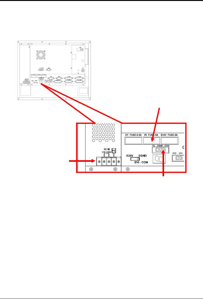
3.3 LNC-M515i system connection and description
A Power
A-3
A-1
A-2
A-1 System Power Supply
Description Offer 5V.12V power for system.Connection Connection as below
|
|
|
AC IN |
FG |
|
Put AC110V/230V power connect to power supply’s AC IN, FG to grounding, please connect with metal chassis (grounding)
LNC Technology Co., Ltd. |
17 |

 LNC-M515i
Hardware Maintenance
External ON/OFF switch to do system power control
Description Put AC power to the back power of LNC-515i, and system will on, but if the external power is needed, wiring and TRF9500 wiring is below
Note 1.The numbers in this graph is to show TRF9500 ON/OFF Connector PIN. 2.please weld the ON switch light with PIN15.
18 |
LNC Technology Co., Ltd. |
 LNC-M515i
Hardware Maintenance
TRF9500 wiring is as below
1 By the definition of ON/OFF Connector, welding with ON/OFF button switch. 2 Connecting with 515i system.
Wiring to ON/OFF buttons
System power
Power
E24V
System power
LNC Technology Co., Ltd. |
19 |
 LNC-M515i
Hardware Maintenance
TRF9500 ON/OFF Connector PIN definition
PIN |
Name |
Description |
1 |
- |
- |
2 |
- |
- |
3 |
- |
- |
4 |
- |
- |
5 |
EGND |
E24V power GND |
6 |
OFF1 |
OFF button PIN 1 |
7 |
- |
- |
8 |
ON1 |
ON button PIN 1(E24V) |
9 |
- |
- |
10 |
- |
- |
11 |
- |
- |
12 |
OFFL |
OFF button light control |
13 |
OFF2 |
OFF button PIN 2 |
14 |
- |
- |
15 |
ON2 |
ON button PIN 2 |
AC power cable we recommend you use PVC cables and the cable diameter is 0.75 mm2 or above material (better within 5m).
Before sending electricity, please make sure the wiring is correct. ( please do not connect AC power to FG, otherwise the controller will be burned out.)
A-2 External E24V Connector
Description E24V is for controller, power control and external I/O to use.Connector Description As below
FG EGND E24V
E24V and EGND connect to external power supply AC output side FG to grounding, please connect with metal chassis (grounding)
Power Demand (1)E24V/5A above
(2)Output voltage ripple and noise is smaller then 150mVp-p.
We recommend you to use the power supply of LNC (E24V/5.8A
E5V/3A). With using this model, LNC have passed the CE test. We can not guarantee your needs without using this model.
When using this power supply, please make sure the installation location will not be too far( DC output may have drop voltage.) After booting, E24V power supply voltage will need to stay within E24V±0.5V.
20 |
LNC Technology Co., Ltd. |

 LNC-M515i
Hardware Maintenance
A-3 FUSE
Description Fuse is the circuit protection. When controller has strange situation, please check if fuse is OK.
Position Description Relating position is as below
OT |
5V |
E24V |
Specification Description 5V/E24V/5V are all 250V/5A OT is 250V/0.5A
B Motion Control
B-2 |
B-1 |
B-3
LNC Technology Co., Ltd. |
21 |

 LNC-M515i
Hardware Maintenance
B-1 Servo Control Connector
Description B-1 offers 4 axis control pin(X Y Z SP) to connect and control back side drives.Connector Description Use D_SUB 25PIN(Jack) connect, details as below
PIN |
Name |
Description |
PIN |
Name |
Description |
|
|
|
|
|
|
|
|
1 |
/PB |
Pulse output /B |
14 |
/PA |
Pulse output /A |
|
|
|
|
|
|
|
|
2 |
PB |
Pulse output B |
15 |
PA |
Pulse output A |
|
|
|
|
|
|
|
|
3 |
E5V |
External E5V for linear scale |
16 |
- |
- |
|
|
|
|
|
|
|
|
4 |
EGND |
External grounding |
17 |
DACO |
Analog voltage output |
|
|
|
|
|
|
|
|
5 |
AGND |
Analog output grounding |
18 |
E24V |
External power E24V |
|
|
|
|
|
|
|
|
6 |
SRV_ON |
Servo start control |
19 |
ALARM |
Servo alarm |
|
|
|
|
|
|
|
|
7 |
EGND |
External power grounding |
20 |
SVI_COM |
Servo COM setting |
|
(E5V E24V |
||||||
|
|
|
|
|
||
8 |
SVI_COM |
Servo COM setting |
21 |
EGND |
External power |
|
grounding |
||||||
|
|
|
|
|
||
9 |
SRV_RST |
Signal reset signal |
22 |
- |
- |
|
|
|
|
|
|
|
|
10 |
C |
Encoder C |
23 |
/C |
Encoder /C |
|
|
|
|
|
|
|
|
11 |
A |
Encoder A |
24 |
/A |
Encoder /A |
|
|
|
|
|
|
|
|
12 |
B |
Encoder B |
25 |
/B |
Encoder /B |
|
|
|
|
|
|
|
|
13 |
FG |
Chassis grounding |
- |
- |
- |
|
|
|
|
|
|
|
Description (1) Pulse output and encoder feedback are all differential signaling. (2)Analog voltage output is ±10V.
(3)The analog voltage output of SP Connector is standard selection, the analog voltage output of other axes are optional.
When making the connection cables of control pin and back-end driver, please use better shielding cover and cables (A.W.G24 UP) And make sure the connection of shielding cables to reduce the chance of noise interference. LNC offers standard cables for selection.
Please don’t bind signal control cables with power cables at the same time or put at the same cable box.
22 |
LNC Technology Co., Ltd. |

 LNC-M515i
Hardware Maintenance
B-2 MPG Control Connector
Description This connector is for MPG to use which includes pulse and IO signal.Connector Description Use D_SUB 25PIN(Jack) connect, details as below:
PIN |
Name |
Description |
PIN |
Name |
Description |
|
|
|
|
|
|
1 |
E5V |
MPG IO power |
9 |
EGND |
MPG power grounding |
|
|
|
|
|
|
2 |
MPG4 |
MPG 4 |
10 |
FG |
Chassis grounding |
|
|
|
|
|
|
3 |
E/B |
Encoder /B |
11 |
EB |
Encoder B |
|
|
|
|
|
|
4 |
E/A |
Encoder /A |
12 |
EA |
Encoder A |
|
|
|
|
|
|
5 |
X100 |
MPG ratio 100 |
13 |
X10 |
MPG ratio 10 |
|
|
|
|
|
|
6 |
MPGZ |
MPG Z |
14 |
MPGY |
MPG Y |
|
|
|
|
|
|
7 |
MPGX |
MPG X |
15 |
E5V |
MPG E5V power |
|
|
|
|
|
|
8 |
E5V |
MPG E5V power |
- |
- |
- |
|
|
|
|
|
|
Description (1) Encoder feedback is differential signal.
(2)This pin offer 6 sets of 5V input for axis direction and ratio selection to use.
B-3 OT& EMG Connect
Description (1) OT connect is the over travel point and a safe point to protect hardware. Normally will be at short-circuit situation.
(2)When you want to make servo on, you will need to make OT and EMG to be short circuit, therefore OT object is close pin. When using several OT objects, please connect with
serial way, and EMG will be short circuit state at normal using.OT Connector Description As below
OT2 OT1
LNC Technology Co., Ltd. |
23 |

 LNC-M515i
Hardware Maintenance
EMG Connector Description As below
EMG2 EMG1
OT/EMG wiring is as below
Connect with over travel b connect


 …
…
EMG
OT_RELEASE
Inner wiring
Because the OT Connector will have usage of parallel connection (1 hole with 2 lines), please make sure the connection is firm in order to prevent malfunction caused by poor contact.
If the OT and EMG PIN is not used, please make it at short-circuit situation.
24 |
LNC Technology Co., Ltd. |
 LNC-M515i
Hardware Maintenance
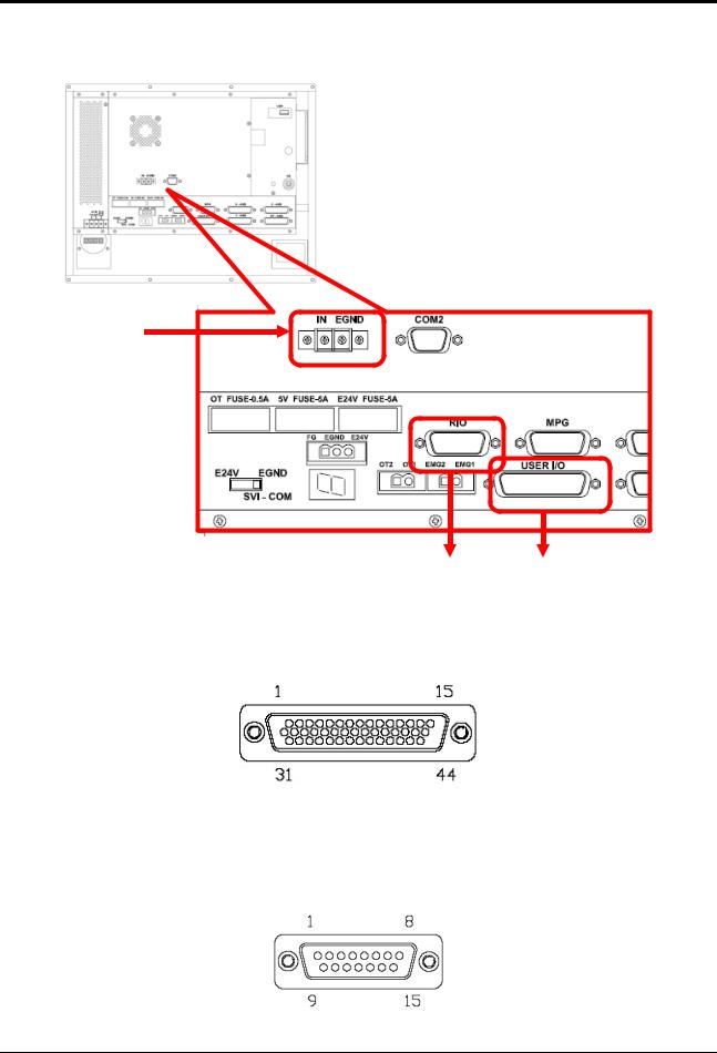
C IO Control
C-3
C-2 C-1
C-1 USER IO Connector
Description C-1offers 20IN/16 OUT-IO interface, usually for connection with REL.Connector Description Adopts HD_SUB 44PIN(Plug), please refer to annex 2 for definition
C-2 RIO Connector
Description C-2 offers IO expansion interface, when USER IO is not enough, you can connect with SIO/EIO from here to do expansion of IO points.
Connector Description Adopts D_SUB 15PIN(Plug) to connect with SIO, one on one.
LNC Technology Co., Ltd. |
25 |

 LNC-M515i
Hardware Maintenance
When making the connection cables of control pin and back-end driver, please use better shielding cover and cables (A.W.G24 UP) And make sure the connection of shielding cables to reduce the chance of noise interference. LNC offers standard cables for selection
(1 9) (2 10) (3 11) (4 12)require the use of stranded cables to prevent noise interference
Please don’t bind signal control cables with power cables at the same time or put at the same cable box.
C-3 Quick IN Connector
Description C-3 offers 1 IN for tool measuring.
Connector Description Connectors use 2PIN JP terminal, details are as below
Quick IN Connector wiring
1.When the sensor is PNP (HIGH motion)
SENSOR IN
26 |
LNC Technology Co., Ltd. |

 LNC-M515i
Hardware Maintenance
2.When the sensor is NPN (LOW motion)
E24V 
SENSOR IN
IN is 24V standard.
C-4 COM2
Description C-4 is COM2 connector, RS232/422/485 can be set by BIOS.Connector Description COM2 connector is D_SUB 9 PIN(plug)connector, as below
RS232/ RS422 / RS485
PIN |
Definition |
PIN |
Definition |
1 |
DCD2/422TX-/485- |
2 |
RXD2/422TX+/485+ |
3 |
TXD2/422RX+ |
4 |
DTR2/422RX- |
5 |
GND |
6 |
DSR2 |
7 |
RTS2 |
8 |
CTS2 |
9 |
RI2 |
10 |
NC |
LNC Technology Co., Ltd. |
27 |

 LNC-M515i
Hardware Maintenance
3.4OP Panel I/O Chart
I Point Name |
I Point Number |
O Point Name |
O Point Number |
|
|
|
|
EDIT |
I320 |
EDIT LED |
O396 |
MEM |
I336 |
MEM LED |
O362 |
MDI |
I368 |
MDI LED |
O361 |
MPG |
I321 |
MPG LED |
O397 |
ZRN |
I337 |
ZRN LED |
O364 |
JOG |
I369 |
JOG LED |
O363 |
Spare(I0.2) |
I322 |
Spare (R9.6) |
O398 |
←X |
I338 |
←X LED |
O366 |
Y |
I370 |
Y LED |
O365 |
↑Z |
I323 |
↑Z LED |
O399 |
RAPID |
I339 |
RAPID LED |
O369 |
↓Z |
I371 |
↓Z LED |
O368 |
Y |
I324 |
Y LED |
O372 |
→X |
I340 |
→X LED |
O371 |
Spare (I6.4) |
I372 |
Spare (O6.2) |
O370 |
CW |
I325 |
CW LED |
O375 |
STOP |
I341 |
STOP LED |
O374 |
CCW |
I373 |
CCW LED |
O373 |
SBK |
I326 |
SBK LED |
O352 |
MPG DRN |
I342 |
MPG DRN LED |
O353 |
LOW |
I374 |
LOW LED |
O354 |
OP STOP |
I327 |
OP STOP LED |
O321 |
BDT |
I343 |
BDT LED |
O324 |
25% |
I375 |
25% LED |
O327 |
MST |
I328 |
MST LED |
O320 |
Spare (I3.0) |
I344 |
Spare (R0.3) |
O323 |
50% |
I360 |
50% LED |
O326 |
Spare (I1.1) |
I329 |
Spare (R8.0) |
O384 |
Spare (I3.1) |
I345 |
Spare (R0.2) |
O322 |
100% |
I361 |
100% LED |
O325 |
MAG CW |
I330 |
MAG CW LED |
O387 |
AIR BLOW |
I346 |
AIR BLOW LED |
O386 |
ORI |
I362 |
ORI LED |
O385 |
MAG CCW |
I331 |
MAG CCW LED |
O388 |
W.L. |
I347 |
W.L. LED |
O341 |
COOL |
I363 |
COOL LED |
O338 |
CHIP CW |
I350 |
CHIP CW |
O389 |
F1 |
I332 |
F1 LED |
O388 |
F2 |
I348 |
F2 LED |
O340 |
F3 |
I364 |
F3 LED |
O337 |
CHIP CCW |
I334 |
CHIP CCW |
O390 |
F4 |
I333 |
F4 LED |
O342 |
F5 |
I349 |
F5 LED |
O339 |
F6 |
I365 |
F6 LED |
O336 |
CYCLE START |
I377 |
CYCLE START LED |
O360 |
FEED HOLD |
I378 |
FEED HOLD LED |
O367 |
SP Speed DOWN |
I379 |
|
|
SP Speed 100% |
I380 |
|
|
SP Speed UP |
I381 |
|
|
Feedrate F%- |
I382 |
|
|
28 |
LNC Technology Co., Ltd. |
 Loading...