


 Loading...
LNC-T/M 5X8A
Maintenance Manual
2012/10 Ver V01.00 (4408210138 )
Leading Numerical Controller
Suitable for T508A T518A M528A T/M568A
LNC Technology Co., Ltd.
|
I |
LNC Technology Co., Ltd. |
|

|
|
|
LNC-Lathe/Mill |
|
|
|
MENU |
|
|
|
|
|
|
MENU |
|
1. Hardware ................................................................................................................... |
|
3 |
|
1.1 |
Specification................................................................................................................................ |
3 |
|
1.2 |
Product form and ports .............................................................................................................. |
4 |
|
1.3 |
System wiring diagram and instructions ................................................................................. |
7 |
|
|
1.3.1 |
System wiring ................................................................................................................... |
7 |
|
1.3.2 |
System wiring instruction ............................................................................................... |
11 |
1.4 |
OP hardware I/O mapping ........................................................................................................ |
22 |
|
1.5 |
PLC I/O Table............................................................................................................................. |
23 |
|
1.6 |
LNC-M5X8A + A-SERIES Inverter communication wiring description ................................ |
24 |
|
|
1.6.1 |
LNC-M5X8A port ............................................................................................................ |
24 |
|
1.6.2 |
A-SERIES Inverter port .................................................................................................. |
25 |
|
1.6.3 |
Cable type ...................................................................................................................... |
25 |
|
1.6.4 |
PIN definition .................................................................................................................. |
26 |
|
1.6.5 |
Notice ............................................................................................................................. |
26 |
1.7 |
I/O SIO 1540 ............................................................................................................................... |
27 |
|
1.8 |
I/O EIO2000 Definition .............................................................................................................. |
32 |
|
1.9 |
RELY 2840 definition ................................................................................................................ |
38 |
|
|
1.7.1 |
Description: .................................................................................................................... |
38 |
|
1.7.2 |
Hardware layout: ............................................................................................................ |
38 |
|
1.7.3 |
Connector description: ................................................................................................... |
38 |
|
1.7.4 |
Setting: ........................................................................................................................... |
39 |
|
1.7.5 |
Connecter PIN definition: ............................................................................................... |
41 |
|
1.7.6 |
Power wiring note:.......................................................................................................... |
42 |
1.10 |
Relay board REL7816D Instruction......................................................................................... |
43 |
|
1.11 |
Annex ......................................................................................................................................... |
|
46 |
2. Dimension and application instruction................................................................. |
49 |
||
2.1 |
Dimension.................................................................................................................................. |
49 |
|
2.2 |
Chassis dimension ................................................................................................................... |
50 |
|
2.3 |
REL2840..................................................................................................................................... |
51 |
|
2.4 |
REL7816D .................................................................................................................................. |
52 |
|
3. Appendix A Servo wiring instruction .................................................................... |
54 |
||
A1 Yaskawa servo................................................................................................................................ |
54 |
||
A2 Panasonic ....................................................................................................................................... |
56 |
||
A3 Mitsubishi........................................................................................................................................ |
|
58 |
|
Appendix B RS232 Connection Description................................................................ |
60 |
||
Appendix C net cable instruction ................................................................................. |
62 |
||
Appendix D LNC MPG wiring instruction .................................................................... |
63 |
||
Appendix E Wiring instruction ..................................................................................... |
64 |
||
A-system wiring diagram .................................................................................................................... |
64 |
||
B-Power wiring..................................................................................................................................... |
73 |
||
C-ControlLoop ..................................................................................................................................... |
78 |
||
D-ONOFF .............................................................................................................................................. |
|
79 |
|
E- SP Terminal interface...................................................................................................................... |
80 |
||
I-INPUT Wiring...................................................................................................................................... |
82 |
||
O-OUTPUT Wiring................................................................................................................................ |
82 |
||
P-Servo power wiring .......................................................................................................................... |
88 |
||
BK-Independent brake servo system ................................................................................................ |
95 |
||
LNC Technology Co., Ltd. |
I |

LNC-Lathe/Mill
Hardware
1. |
Hardware |
|
|
1.1 |
|
Specification |
|
|
|
|
|
|
|
LNC-T/M 5X8 |
SPEC |
|
|
|
|
|
|
Monitor |
8" TFT LCD |
|
|
|
|
|
|
SD RAM |
256MB |
|
|
|
|
|
|
System CF Card |
1Gor above |
|
|
|
|
|
|
Data Interface |
USB/CF/LAN |
|
|
|
|
|
|
USER I/O |
20Input/16 Output, up to 2 set |
|
|
|
|
|
|
|
1 Port, use with SIO/EIO to extend I/O board |
|
|
Serial I/O |
upto 128IN/128OUT. (only available on |
|
|
|
T/M568A) |
|
|
MPG Interface |
3 in 1 MPG, include IN and Encoder |
|
|
|
|
|
|
Control Axes |
Max. 6 axes( include Spindle) |
|
|
T/M568A has 6 axes; T518/M528 has 4 axes |
|
|
|
|
|
|
|
Power |
AC 110V/240V 50Hz/60Hz input power |
|
|
|
|
LNC- T/M 5X8A System Power Demand
Power Category |
Specification |
Usage |
NOTE |
|
|
|
|
System Power |
AC110V/240V 50Hz/60Hz |
For System |
|
|
|
|
|
External Power(24V) |
DC24V/(4A UP) |
For external IO |
|
|
|
|
|
LNC Technology Co., Ltd. |
3 |
LNC-Lathe/Mill
Hardware
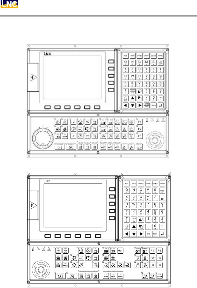
1.2Product form and ports
T 5X8A Controller Front View (right side MPG is also available)
M 5X8A Controller Front View
4 |
LNC Technology Co., Ltd. |
LNC-Lathe/Mill
Hardware
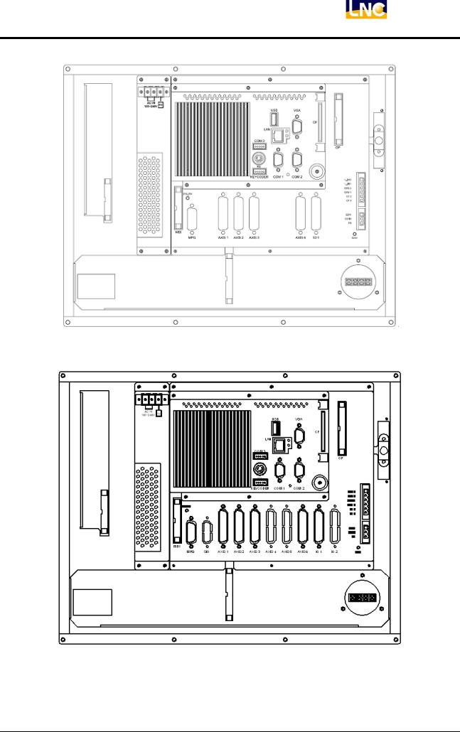
T 518A Controller Back View
T 568A Controller Back View
LNC Technology Co., Ltd. |
5 |
LNC-Lathe/Mill
Hardware
M 528A Controller Back View
M 568A Controller Back View
6 |
LNC Technology Co., Ltd. |
LNC-Lathe/Mill
Hardware
1.3System wiring diagram and instructions
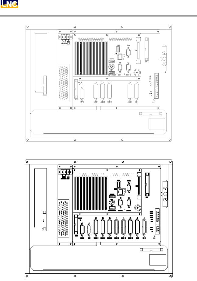
1.3.1 System wiring Wiring on controller
MDI
OP
T 5X8A Wiring on controller
MDI
OP
M 5X8A Wiring on controller
LNC Technology Co., Ltd. |
7 |
LNC-Lathe/Mill
Hardware
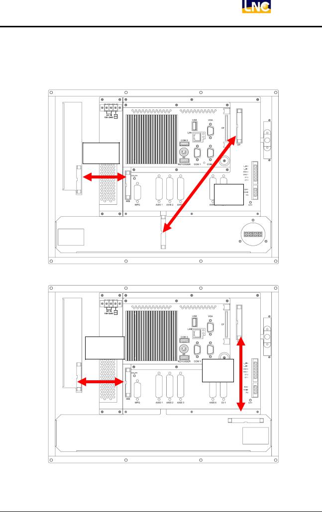
USB
VGA output
CF
KEYBOARD
Ethernet
RS232 |
For RS232/422/485 |
8 |
LNC Technology Co., Ltd. |
LNC-Lathe/Mill
Hardware
Motion ports and IO, accessories
Note: SIO only availible on T/M 568A
LNC Technology Co., Ltd. |
9 |
LNC-Lathe/Mill
Hardware
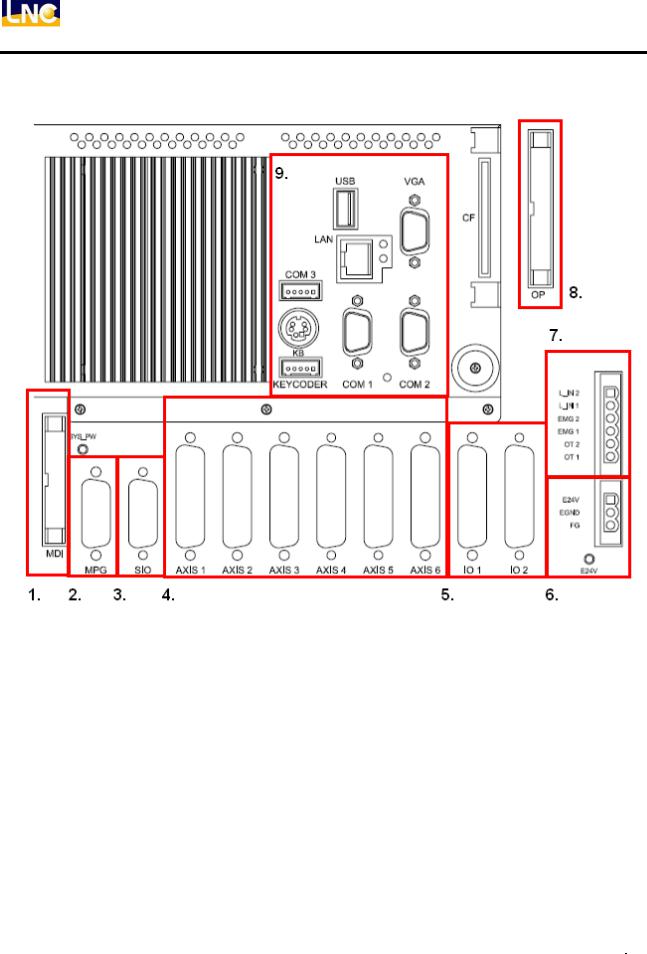
Connectors
Item |
Ports |
Function |
|
Connector |
Remark |
|
|
|
|||||
1 |
MDI |
MDI |
|
2.54mm 26PIN IDC |
|
|
|
|
|
|
|
|
|
2 |
MPG |
MPG port |
|
D-SUB 15 PIN( Female) |
Include command |
and |
|
IN |
|
||||
|
|
|
|
|
|
|
3 |
Serial I/O |
I/O extand port |
|
D-SUB 15 PIN(Male |
Avalible on T/M 568A |
|
|
|
|
|
|
|
|
|
|
|
|
|
T518A/M528A |
has |
4 |
AXIS 1~6 |
Axis |
|
D-SUB 25 PIN( Female) |
4axes |
|
|
(AXIS1~3 AXIS6) |
|||||
|
|
|
|
|
||
|
|
|
|
|
T/M568A has 6 axes |
|
|
|
|
|
|
T518A/M528A IO2 is |
|
5 |
USER I/O |
20IN/16OUT |
|
HD_D-SUB 44 PIN(Male) |
optional;T/M568A |
IO2 |
|
|
|
|
|
is standard |
|
6 |
E24V EGND FG |
24V Input |
|
3PIN 5.08mm terminals |
|
|
|
|
|
|
|
|
|
7 |
Local_IN/EMG/OT |
Tool Measure |
and |
6PIN 5.08mm terminals |
|
|
|
|
Safety function |
|
|
|
|
8 |
OP |
Connect to OP |
|
2.54mm 34 PIN IDC |
|
|
|
|
|
|
|
|
|
9 |
|
PC interface |
|
Regular PC interface |
|
|
10 |
LNC Technology Co., Ltd. |

LNC-Lathe/Mill
Hardware
1.3.2 System wiring instruction
A Power input
L_IN 2
L_IN 1
EMG 2
EMG 1
OT 2
OT 1
A-2
A-1
E24V
EGND
FG
A-1 System power supply
Details Offer 5V.12V power for system.
Terminal details as following
|
|
|
AC IN |
FG |
|
Put AC110V/230V power connect to power supply’s AC IN, FG to grounding, please connect with metal chassis (grounding)
LNC-T/M 5X8A POWER will power on when AC power input, no other switch. If you need a switch, please arrange with TRF9500 ON/OFF switch board.
LNC Technology Co., Ltd. |
11 |
LNC-Lathe/Mill
Hardware
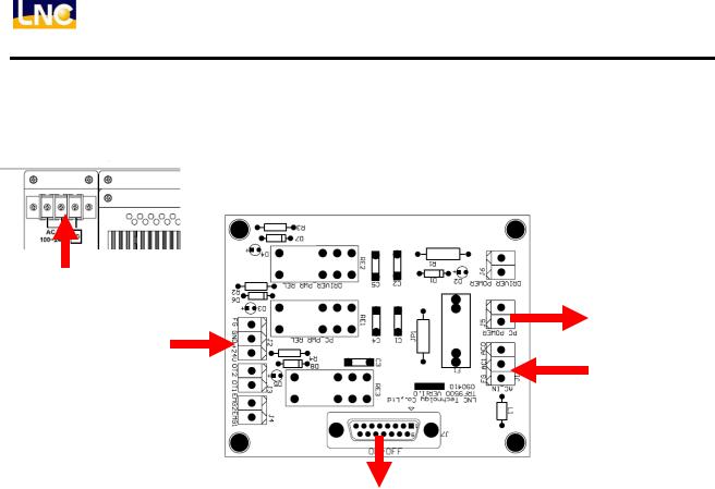
TRF9500 On/OFF switch board
Step 1:
Power in
To controller
E24V in
AC in
Wire to ON/OFF switch
Step 2:
ON/OFF connector signal (PIN define as following) connect with ON/OFF button
PIN |
Name |
Description |
1 |
- |
- |
2 |
- |
- |
3 |
- |
- |
4 |
- |
- |
5 |
EGND |
E24V power GND |
6 |
OFF1 |
OFF button PIN 1 |
7 |
- |
- |
8 |
ON1 |
ON button PIN 1(E24V) |
9 |
- |
- |
10 |
- |
- |
11 |
- |
- |
12 |
OFFL |
OFF button light control |
13 |
OFF2 |
OFF button PIN 2 |
14 |
- |
- |
15 |
ON2 |
ON button PIN 2 |
12 |
LNC Technology Co., Ltd. |
LNC-Lathe/Mill
Hardware
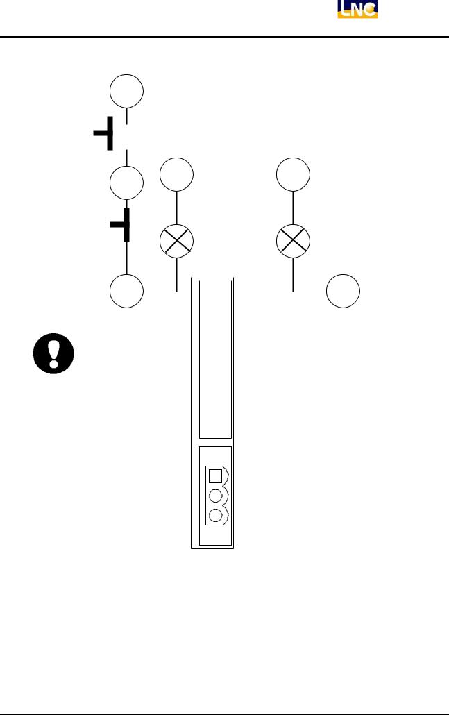
ON/OFF button PIN Wiring:
8
ON button A Pin
6 |
12 |
15 |
|
ON light (+) |
OFF Light (+) |
OFF Button B PIN
ON Light (-) |
OFF Light (-) |
|
13 |
|
|
5 |
|
|
L_IN 2 |
||
|
|
L_IN 1 |
||
|
AC power cable: We recommend you use PVC cables and the cable |
|||
|
diameter is 0.75 mm2 or above material (better within 5m). |
|||
|
EMG 2 |
|||
|
Before sending electricity, please make sure the wiring is correct. (Please |
|||
|
do not connect AC power to FG; otherwise the controller will be burned |
|||
|
out.)EMG 1 |
|||
A-2: External E24V Connector |
OT 2 |
|||
Description:E24V is for controller,OTpower1 control and external I/O to use.
Connector Description: As below:
E24V
EGND
FG
E24V and EGND connect to external power supply AC output side FG to grounding, please connect with
metal chassis (grounding)
Power Demand :
(1)E24V/4A above
(2)Output voltage ripple and noise is smaller than 150mVp-p.
LNC Technology Co., Ltd. |
13 |
LNC-Lathe/Mill
Hardware
We recommend you to use the power supply of LNC (E24V/5.8A, E5V/3A). With using this model, LNC have passed the CE test. We cannot guarantee your needs without using this model.
When using this power supply, please make sure the installation location will not be too far (DC output may have drop voltage.) After booting, E24V power supply voltage will need to stay within E24V±0.5V.
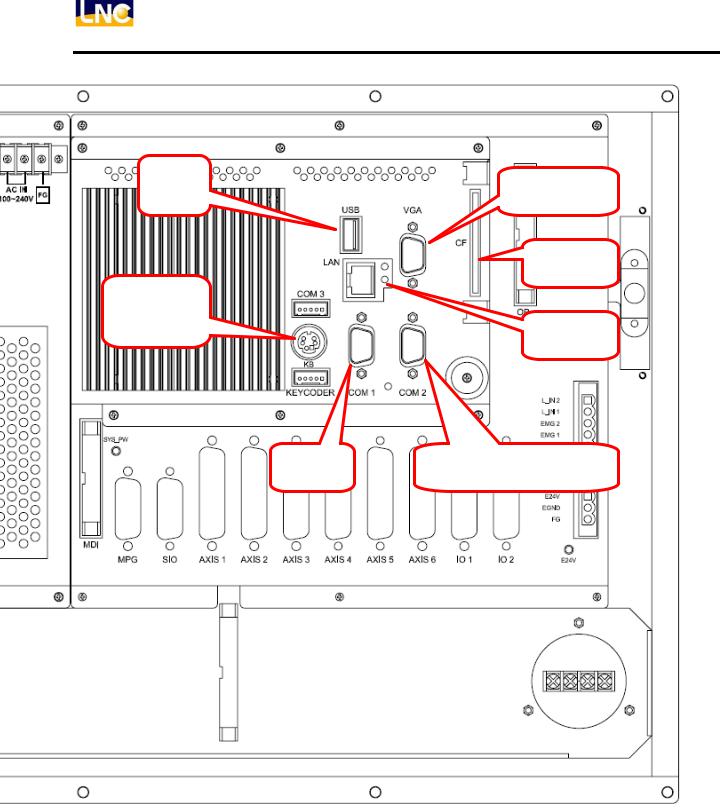
B Motion Control:
|
USB |
VGA |
|
|
CF |
LAN |
|
|
COM 3 |
|
|
|
|
OP |
B-2 |
B-1 |
B-3 |
KB |
|
|
KEYCODER |
COM 1 |
COM 2 |
|
|
L_IN 2 |
|
|
L_IN 1 |
|
|
EMG 2 |
SYS_PW |
|
EMG 1 |
|
|
|
|
|
OT 2 |
|
|
OT 1 |
E24V
EGND
FG
MDI
MPG |
SIO |
AXIS 1 AXIS 2 AXIS 3 AXIS 4 AXIS 5 AXIS 6 |
IO 1 |
IO 2 |
E24V |
Note: T/M 568A Support 6 Axes
14 |
LNC Technology Co., Ltd. |

LNC-Lathe/Mill
Hardware
B-1: Servo Control Connector
Description:B-1 offers 4 axis control pin(X, Y, Z, SP) to connect and control back side drives.
Connector Description: Use D_SUB 25PIN (Jack) connect, details as below:
PIN |
Name |
Description |
PIN |
Name |
Description |
|
|
|
|
|
|
|
|
1 |
/PB |
Pulse output /B |
14 |
/PA |
Pulse output /A |
|
|
|
|
|
|
|
|
2 |
PB |
Pulse output B |
15 |
PA |
Pulse output A |
|
|
|
|
|
|
|
|
3 |
E5V |
External E5V for linear |
16 |
- |
- |
|
scale |
||||||
|
|
|
|
|
||
4 |
EGND |
External grounding |
17 |
DACO |
Analog voltage output |
|
|
|
|
|
|
|
|
5 |
AGND |
Analog output grounding |
18 |
E24V |
External power E24V |
|
|
|
|
|
|
|
|
6 |
SRV_ON |
Servo start control |
19 |
ALARM |
Servo alarm |
|
|
|
|
|
|
|
|
7 |
EGND |
External power grounding |
20 |
SVI_COM |
Servo COM setting |
|
(E5V,E24V) |
||||||
|
|
|
|
|
||
8 |
SVI_COM |
Servo COM setting |
21 |
EGND |
External power |
|
grounding |
||||||
|
|
|
|
|
||
9 |
SRV_RST |
Signal reset signal |
22 |
- |
- |
|
|
|
|
|
|
|
|
10 |
C |
Encoder C |
23 |
/C |
Encoder /C |
|
|
|
|
|
|
|
|
11 |
A |
Encoder A |
24 |
/A |
Encoder /A |
|
|
|
|
|
|
|
|
12 |
B |
Encoder B |
25 |
/B |
Encoder /B |
|
|
|
|
|
|
|
|
13 |
FG |
Chassis grounding |
- |
- |
- |
|
|
|
|
|
|
|
Remark:
(1)Axis 5, 6 with E5V, Axis 5: ±10V voltage output(optional), Axis 6: offer ±10V voltage output, as
following chart
4 axis |
Support 1 analog |
|
Support 2 analog |
||
|
||
6 axis |
Support 1 analog |
|
Support 2 analog |
||
|
(2)Only SP Connector has both analog ±10V and pulse E5V output. Other axis only has E5V output.
When making the connection cables of control pin and back-end driver, please use better shielding cover and cables (A.W.G24 UP) And make sure the connection of shielding cables to reduce the chance of noise interference. LNC offers standard cables for selection.
Please don’t bind signal control cables with power cables at the same time or put at the same cable box.
LNC Technology Co., Ltd. |
15 |
LNC-Lathe/Mill
Hardware
B-2: MPG Control Connector
Description: This connector is for MPG to use which includes pulse and IO signal.
Connector Description: Use D_SUB 25PIN (Jack) connect, details as below:
PIN |
Name |
Description |
PIN |
Name |
Description |
|
|
|
|
|
|
1 |
E5V |
MPG IO power |
9 |
EGND |
MPG power grounding |
|
|
|
|
|
|
2 |
MPG4 |
MPG 4 |
10 |
FG |
Chassis grounding |
|
|
|
|
|
|
3 |
E/B |
Encoder /B |
11 |
EB |
Encoder B |
|
|
|
|
|
|
4 |
E/A |
Encoder /A |
12 |
EA |
Encoder A |
|
|
|
|
|
|
5 |
X100 |
MPG ratio 100 |
13 |
X10 |
MPG ratio 10 |
|
|
|
|
|
|
6 |
MPGZ |
MPG Z |
14 |
MPGY |
MPG Y |
|
|
|
|
|
|
7 |
MPGX |
MPG X |
15 |
E5V |
MPG E5V power |
|
|
|
|
|
|
8 |
E5V |
MPG E5V power |
- |
- |
- |
|
|
|
|
|
|
Description:
(1)Encoder feedback is differential signal.
(2)This pin offer 6 sets of 5V input for axis direction and ratio selection to use.
(3)PIN 1 can be used for MPG IN power, but don’t use 24V to avoid damage.
B-3: OT& EMG Connect
Description:
(1)OT connect is the over travel point and a safe point to protect hardware. Normally will be at short-circuit situation.
(2)When you want to make servo on, you will need to make OT and EMG to be short circuit, therefore OT object is close pin. When using several OT objects, please connect with serial way, and EMG will be short circuit state at normal using.
(3)If you use the EMG on OP, no need to short EMG1/ EMG2.
Because the OT Connector will have usage of parallel connection (1 hole with 2 lines), please make sure the connection is firm in order to prevent malfunction caused by poor contact.
If the OT and EMG PIN are not used, please make it at short-circuit situation.
16 |
LNC Technology Co., Ltd. |
LNC-Lathe/Mill
Hardware
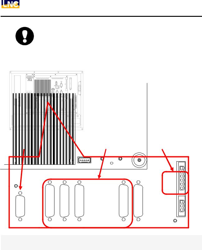
C, IO Control:
Note:only T/M 568A Support SIO
C-1 ON_BOARD IO connector
Detail: T/M 5X8A offers 1 I/O port (connect to 20IN/16OUT REL board), O is 24V level, Max. current 60mA, I is NPN/PNP switchable.
USER IO Connector
Description:C-1offers 20IN/16 OUT IO interface, usually for connection with RELY board.
Connector Description: Adopts HD_SUB 44PIN (Plug), please refer to appendix 1 for definition: PIN
LNC Technology Co., Ltd. |
17 |
LNC-Lathe/Mill
Hardware
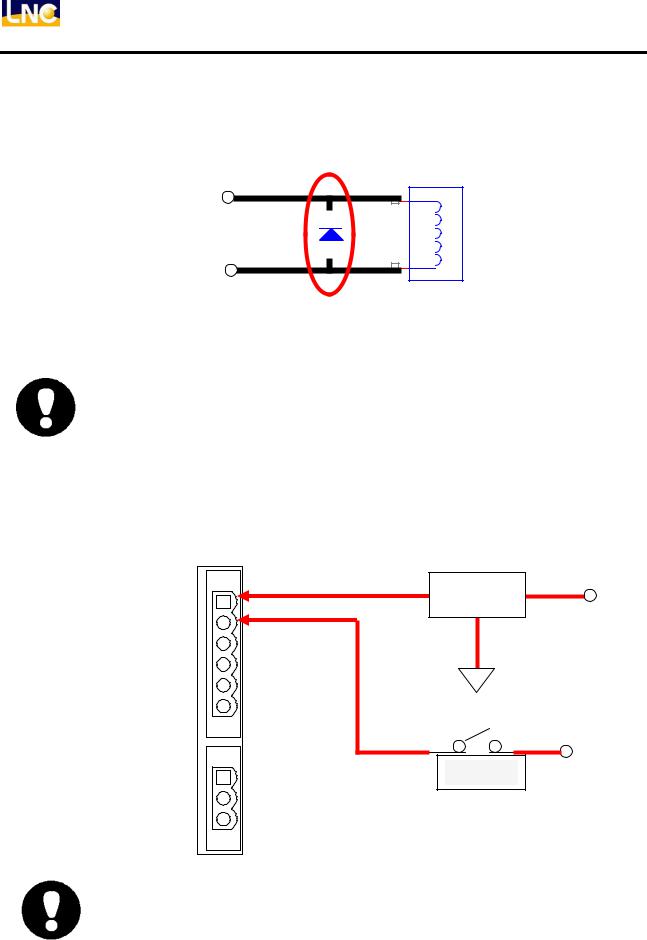
Out point usage: If you want use Output point without RELY board, use inductive load please arrange with flywheel diode for protection purpose.
OUT
EGND
Recommend item: IN4007
1 2
Flywheel diode
+
3 |
Inductive load
1 |
S
-
Max current loading is 60 mA, otherwise will cause damage.
E.G. E24V/60 mA=400Ω Loading resistor must higher than this.
When use inductive loads (E.g. RELAY), please add flywheel diode for protection purpose.
If OUT point short with ground, IC will be burned right away.
C-2: Quick IN Connector
Description: C-3 offers 2 IN for tool measuring.
Connector Description: Connector’s use 2PIN JP terminal, details are as below:
L_IN 2 |
SENSOR IN |
E24V |
|
|
|
L_IN 1 |
|
|
EMG 2 |
|
|
EMG 1 |
EGND |
|
|
|
|
OT 2 |
|
|
OT 1 |
|
|
|
|
E24V |
E24V |
Contacts |
|
EGND |
|
|
FG |
|
|
IN is 24V standard and same source with E24V, EGND, otherwise reading will be abnormal.
18 |
LNC Technology Co., Ltd. |
LNC-Lathe/Mill
Hardware
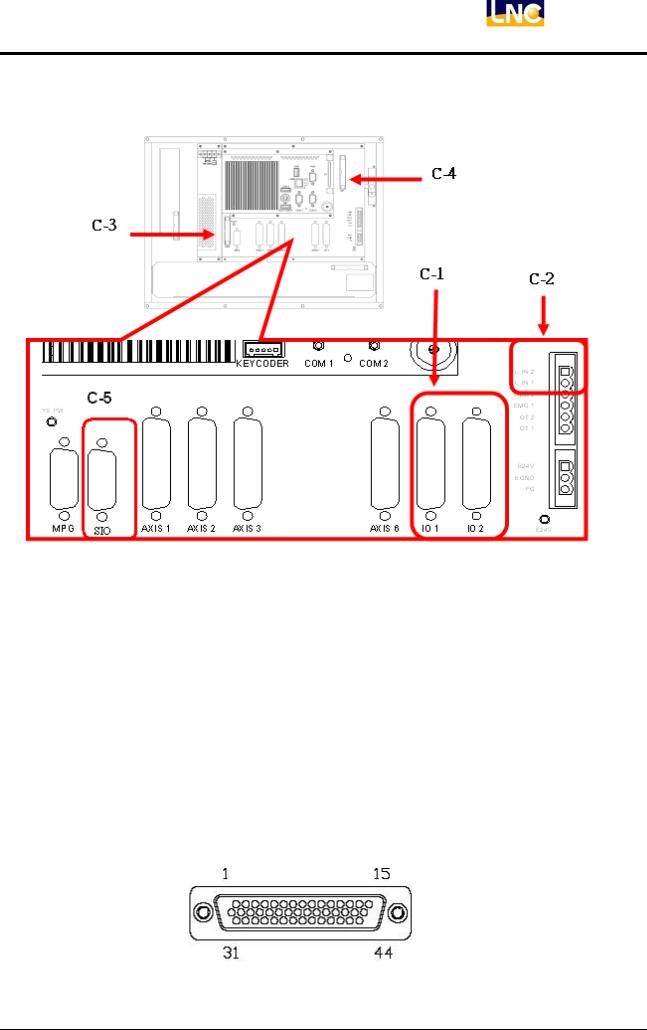
C-3 MDI
Description: Use for connect to MDI.
Connector Description: 2.54mm 26PIN IDC
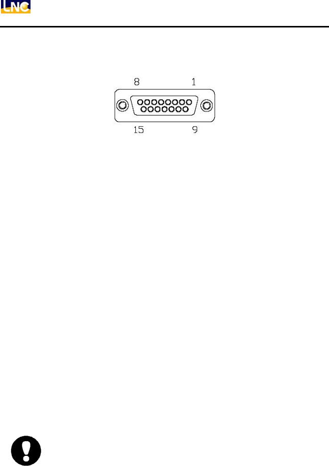
C-4 OP Connector
Description Offering for OP connecting, max 80IN/80OUT, power level 5V DC.
Connector Description 2.54mm 34 PIN IDC Connector
C-5 Serial IO port
SIO port
Detail C-2 used for extand I/O port, ues with SIO/EIO boards to extand I/O board. Connector: D_SUB 15PIN( Male), connect to SIO/EIO board
This control port MUST use with shelled cable and large then A.W.G24, LNC offer standard cable for this.
(1 9) (2 10) (3 11) (4 12)Need twisted cable.
DO NOT set these cables with POWER cables on panel box.
I/O card and SIO module
LNC-T/M 568A can extand the I/O control upto 128IN/128OUT following are the wiring diagram:
LNC Technology Co., Ltd. |
19 |
LNC-Lathe/Mill
Hardware
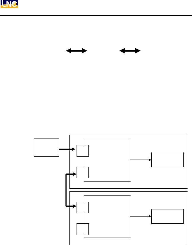
Serial I/O functions as following
|
Serial master |
|
Slave |
|
Relay board |
|
|
|
|
|
|
|
|
|
|
|
|
Controller |
|
SIO-1520 |
|
REL-2840 |
|
SIO-1540
EIO-2000
Operation Panel
Serial I/O connect as following: (1 PORT accept upto 2 slave board)
controller |
Slave1 |
|
SIO port |
P1 |
|
|
Slave board |
Relay board |
|
P2 |
|
|
Slave2 |
|
|
P1 |
|
|
Slave board |
Relay board |
|
P2 |
|
20 |
LNC Technology Co., Ltd. |

LNC-Lathe/Mill
Hardware
Serial I/O extanded I/O pints:
Modules
Controller site (MASTER)
Hardware |
Serial port |
|
Remark |
LNC-T/M 568A |
1 |
|
|
|
|
|
|
I/O extand board(SLAVE, each can serialy extand) |
|||
Hardware |
I/O points |
Remark |
|
SIO-1540 |
40IN / 32OUT |
|
|
EIO-2000-1 |
40IN / 32OUT |
|
|
EIO-2000-2 |
60IN / 48OUT |
|
|
SIO-1520 |
40IN / 32OUT |
Used for Operation Panel |
|
OP-2520 |
64IN / 64OUT |
Used for Operation Panel |
|
|
|
|
|
|
User I/O port |
|
|
Hardware |
I/O |
|
Remark |
REL-2840 |
20IN / 16OUT |
|
|
I/O port amount:
(1)LNC-T/M 568A, with EIO-2000-2, max I/O point is 1(SIO) × 2( EIO-2000-2) × 60 IN = 120IN
1(SIO) × 2( EIO-2000-2) × 48 OUT = 96 OUT
(2)LNC-T/M 568A, with SIO-1540, max I/O is 1(SIO) × 2( SIO-1540) × 40 IN = 80IN 1(SIO) × 2( SIO-1540) × 32 OUT = 64 OUT And so on.
Each hardware set up according to it’s user manual.
OP Connector I/O points are all 5V level, if connect higher than 5V, it will damage the board.
LNC Technology Co., Ltd. |
21 |

LNC-Lathe/Mill
Hardware
1.4OP hardware I/O mapping
PLC ladder to match with.
T 5X8A |
M 5X8A |
|
|
LNC Technology Co., Ltd.

LNC-Lathe/Mill
Hardware
1.5PLC I/O Table
IN/OUT Table
I 0 |
L-IN0 |
, |
Local Input with Latch function |
O 0 |
|
|
|
|
|
|
|
|
|
I 1 |
L-IN1 |
, |
Local Input with Latch function |
O 1 |
|
|
|
|
|
|
|
|
|
I 2 |
EMG |
|
|
O 2 |
|
|
|
|
|
|
|
|
|
I 3 |
|
|
|
O 3 |
Servo_Reset |
|
|
|
|
|
|
|
|
I 4 |
|
|
|
O 4 |
|
|
|
|
|
|
|
|
|
I 5 |
|
|
|
O 5 |
Watch Dog(For Systems) |
|
|
|
|
|
|
|
|
I 6 |
MPG Axis_X |
O 6 |
|
|
||
|
|
|
|
|
|
|
I 7 |
MPG Axis_Y |
O 7 |
|
|
||
|
|
|
|
|
|
|
I 8 |
MPG Axis_Z |
O 8 |
|
|
||
|
|
|
|
|
|
|
I 9 |
MPG Axis_4 |
O 9 |
|
|
||
|
|
|
|
|
|
|
I 10 |
MPG Axis_5 |
O 10 |
|
|
||
|
|
|
|
|
|
|
I 11 |
MPG Axis_6 |
O 11 |
|
|
||
|
|
|
|
|
|
|
I 12 |
MPG Rate_x10 |
O 12 |
|
|
||
|
|
|
|
|
|
|
I 13 |
MPG Rate_x100 |
O13 |
|
|
||
|
|
|
|
|
|
|
I 14 |
Servo_Alarm_X |
O14 |
|
|
||
|
|
|
|
|
|
|
I 15 |
Servo_Alarm_Y |
O15 |
|
|
||
|
|
|
|
|
|
|
I 16 |
Servo_Alarm_Z |
O16 |
|
|
||
|
|
|
|
|
|
|
I 17 |
Servo_Alarm_4 |
O17 |
|
|
||
|
|
|
|
|
|
|
I 18 |
Servo_Alarm_5 |
O18 |
|
|
||
|
|
|
|
|
|
|
I 19 |
Servo_Alarm_6 |
O 19 |
|
|
||
|
|
|
|
|
|
|
|
|
|
|
O 20 |
Servo_On_All |
Servo_On_X |
|
|
|
|
|
|
|
|
|
|
|
O 21 |
|
Servo_On_Y |
|
|
|
|
|
|
|
|
|
|
|
O 22 |
|
Servo_On_Z |
|
|
|
|
|
|
|
|
|
|
|
O 23 |
|
Servo_On_4 |
|
|
|
|
|
|
|
|
|
|
|
O 24 |
|
Servo_On_4 |
|
|
|
|
|
|
|
|
|
|
|
O 25 |
|
Servo_On_6 |
|
|
|
|
|
|
|
I64~I143 |
OP KEY |
|
O64~O143 |
OP LED |
|
|
|
|
|
|
|
|
|
I144~I163 |
I/O1 INPUT0~19 |
O144~O159 |
I/O1 OUTPUT0~15 |
|
||
|
|
|
|
|
||
I164~I183 |
I/O2 INPUT0~19 |
O160~O175 |
I/O2 OUTPUT0~15 |
|
||
|
|
|
|
|
|
|
I192~I255 |
RIO 0~63 |
|
O192~O255 |
RIO 0~63 |
|
|
|
|
|
|
|
||
I256~I319 |
RIO 64~127 |
O256~O319 |
RIO 64~127 |
|
||
|
|
|
|
|||
I320~I399 |
Serial communication I/O |
O320~O399 |
Serial communication OUT |
|||
|
|
|
|
|
|
|
LNC Technology Co., Ltd. |
23 |
LNC-Lathe/Mill
Hardware
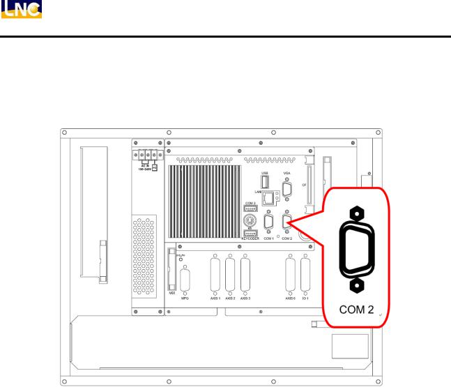
1.6LNC-M5X8A + A-SERIES Inverter communication wiring description
1.6.1LNC-M5X8A port
Use LNC-M5X8A COM2 Port
24 |
LNC Technology Co., Ltd. |
LNC-Lathe/Mill
Hardware
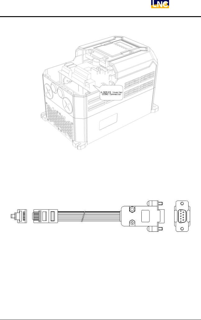
1.6.2A-SERIES Inverter port
Use A-SERIES CCON3 Port
1.6.3Cable type
A-SERIES Inverter communication cable
LNC Technology Co., Ltd. |
25 |
LNC-Lathe/Mill
Hardware
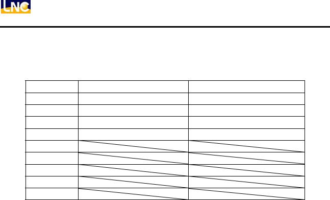
1.6.4PIN definition
PIN |
A-SERIES CCON3 Port |
LNC-M5X8A COM2 Port |
1 PIN |
RX- |
TX- |
2 PIN |
RX+ |
TX+ |
3PIN |
TX+ |
RX+ |
4 PIN |
TX- |
RX- |
5 PIN |
|
|
6 PIN |
|
|
7 PIN |
|
|
8PIN |
|
|
9 PIN |
|
|
1.6.5Notice
1.Need to make COM2 to be RS422.
2.A-SERIES Inverter communication cable is special cable, only supply by LNC.
3.available in 1M, 3M, 5M, 7M
26 |
LNC Technology Co., Ltd. |
LNC-Lathe/Mill
Hardware
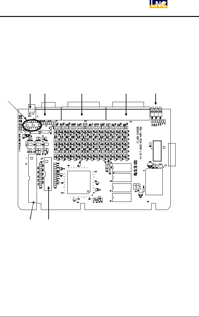
1.7I/O SIO 1540
I/O-SIO 1540 definition
1.Description:
1.SIO-1540 offers 40 IN /32 OUT(also 24 IN / 32 OUT option)
2.Hardware layout:
A B D E H
I
 C
C
F G
LNC Technology Co., Ltd. |
27 |

LNC-Lathe/Mill
Hardware
2.Connector description:
Power
Picture |
Type |
Function |
Usage |
A |
3PIN 3.81mm head |
DC(24V) POWER INPUT |
To POWER |
Light |
|
|
|
Picture |
Type |
Function |
Usage |
H |
E5V GREEN LED |
E5V indicator light |
E5V normal>ON |
|
E24V GREEN LED |
E24V indicator light |
E24V normal>ON |
|
|
|
|
|
CS YELLOW LED |
Transmission Light |
Connect to controller>On |
|
|
|
|
|
DO YELLOW LED |
Transmission Light |
Connect to controller>On |
|
|
|
|
|
DI YELLOW LED |
Transmission Light |
OK>Lights on |
|
|
|
|
|
LK YELLOW LED |
Transmission Light |
OK>Lights on |
|
|
|
|
IO Connector |
|
|
|
Picture |
Type |
Function |
Usage |
B |
D_SUB HD 15PIN Jack |
Serial Port |
To Controller RIO |
C |
16PIN 2.54mm easy head |
Serial Port |
To Controller RIO |
D |
D_SUB HD 44PIN Plug |
Back 20 IN/16 OUT |
To REL |
E |
D_SUB HD 44PIN Jack |
Front 20 IN/16 OUT |
To REL |
F |
40PIN 2.54 mm easy head |
Spare 32 O points |
OPTION |
G |
26PIN 2.54 mm easy head |
Spare 24 I points |
OPTION |
Setting |
|
|
|
Picture |
Type |
Function |
Usage |
I |
2.54mm JUMPER |
SLAVE number setting |
Later chapter |
28 |
LNC Technology Co., Ltd. |
Loading...