


LNC-M520 Series
Maintenance Manual
2008/2 Ver V04.00.002(4408210026)
Leading Numerical Controller
LNC Technology Co., Ltd.

 LNC-M520 Series
Table of Content
Table of Content
1 |
SPECIFICATION ....................................................................................... |
1 |
||
|
1.1 |
Normal Specification & Option Specification ............................................................................... |
1 |
|
|
1.2 |
Standard LNC-520i .................................................................................................................... |
2 |
|
2 |
Software Maintenance............................................................................. |
3 |
||
|
2.1 |
LNC-M520i Installation Description ............................................................................................ |
3 |
|
|
|
2.1.1 |
Installation Program Guide............................................................................................. |
3 |
|
|
2.1.2 System Software Maintenance and Upgrade.................................................................. |
5 |
|
|
2.2 |
SYSTEM DIRECTORIES........................................................................................................... |
6 |
|
|
|
2.2.1 |
[OS.UTILITY]................................................................................................................. |
6 |
|
|
2.2.2 |
[LNC_M520i INSTALL DISK].......................................................................................... |
6 |
3 |
Hardware Maintenance............................................................................ |
7 |
||
|
3.1 |
Specification .............................................................................................................................. |
7 |
|
|
|
3.1.1 |
Connector Pin and Interface .......................................................................................... |
9 |
|
|
3.1.2 |
LNC-520i Controller Wiring Chart................................................................................. |
13 |
|
|
3.1.3 |
Connector Pin Definition .............................................................................................. |
15 |
|
|
3.1.4 Description of Interface Using ...................................................................................... |
20 |
|
|
|
3.1.5 |
I/O Corresponding Table .............................................................................................. |
22 |
|
3.2 |
I/O card SIO 1520.................................................................................................................... |
23 |
|
|
|
3.2.1 |
I/O Card Specification .................................................................................................. |
24 |
|
|
3.2.2 SIO 1520 Connector Pin Definition............................................................................... |
27 |
|
|
3.3 |
I/O Card SIO 1530 Definition.................................................................................................... |
30 |
|
|
|
3.3.1 |
I/O Card Specification .................................................................................................. |
30 |
|
|
3.3.2 |
SIO 1530 Port Definition .............................................................................................. |
31 |
|
|
3.3.3 I/O Card SIO 1540 Definition ....................................................................................... |
33 |
|
|
3.4 |
REL 1820 Definition................................................................................................................. |
38 |
|
|
|
3.4.1 |
Relay Board Specification............................................................................................ |
38 |
|
|
3.4.2 REL 1820 Connector Pin Definition.............................................................................. |
39 |
|
|
3.5 |
REL 2840 Definition................................................................................................................. |
40 |
|
|
|
3.5.1 |
Relay Board Specification............................................................................................ |
40 |
|
|
3.5.2 |
REL 2840 Connection Pin Define................................................................................. |
42 |
|
3.6 |
Self-Protect Strcuture............................................................................................................... |
44 |
|
|
|
3.6.1 |
Double CF Cards......................................................................................................... |
44 |
|
|
3.6.2 |
RamDisk...................................................................................................................... |
46 |
LNC Technology Co., Ltd. |
I |

 LNC-M520i Series
Table of Content
|
|
3.6.3 Installation Checking List of Double CF Card & RamDisk ............................................. |
47 |
4 PLC Maintenance -- C S BITS and Register ..................................... |
49 |
||
|
4.1 |
C Bits Definition ....................................................................................................................... |
49 |
|
4.2 |
S Bits Definition ....................................................................................................................... |
53 |
|
4.3 |
Register Definition ................................................................................................................... |
57 |
|
4.4 |
C Bits Description .................................................................................................................... |
59 |
|
4.5 |
S Bits Description .................................................................................................................... |
69 |
|
4.6 |
Register Description................................................................................................................. |
79 |
|
4.7 |
PLC Window Function ............................................................................................................. |
85 |
|
4.8 |
PLC Initial Setting Description PLCIO.CFG ........................................................................ |
88 |
5 |
Parameter ............................................................................................... |
90 |
|
|
5.1 |
Parameter List ......................................................................................................................... |
91 |
|
5.2 |
Servo Parameter.................................................................................................................... |
107 |
|
5.3 |
Machine Parameter................................................................................................................ |
121 |
|
5.4 |
Spindle Parameter ................................................................................................................. |
124 |
|
5.5 |
MPG Parameter..................................................................................................................... |
145 |
|
5.6 |
Compensation Parameter ...................................................................................................... |
148 |
|
5.7 |
Zero Return Parameter .......................................................................................................... |
155 |
|
5.8 |
Operation Parameter ............................................................................................................. |
172 |
6 SYSTEM ALARM MESSAGE and WARNING MEASSAGE ............... |
199 |
||
|
6.1 |
OP OPERATION RELATED ALARM ...................................................................................... |
200 |
|
6.2 |
INT INTERPRETATION RELATED ALARM ............................................................................ |
204 |
|
6.3 |
MOT MOTION RELATED ALARM.......................................................................................... |
213 |
7 |
Machine Adjustment............................................................................ |
224 |
|
|
7.1 |
Riggid Tapping Commands .................................................................................................... |
224 |
|
7.2 |
Laser Compensation Procedure............................................................................................. |
228 |
|
7.3 |
DOUBLE BALL BAR Measure – Backlash or Circular Spike ................................................... |
232 |
|
7.4 |
M20 Spindle Adjustment ...................................................................................................... |
234 |
8 |
Dimension............................................................................................. |
235 |
|
|
8.1 |
Dimension Figure................................................................................................................... |
235 |
|
8.2 |
Dimension Figure................................................................................................................... |
236 |
|
8.3 |
CF Card Installation Figure .................................................................................................... |
237 |
APPENDIX A PARAMETER ADJUSTMENT EXAMPLE ........................ |
239 |
||
II |
LNC Technology Co., Ltd. |

|
|
LNC-M520 Series |
|
|
Table of Content |
A1 |
Parameter Adjustment of V Command Control Method .............................................................. |
239 |
A2 |
Parameter Adjustment when Encoder is installed besides Ball Screw ........................................ |
242 |
A3 |
Parameter Adjustment when using Linear Scale Control Method ............................................... |
244 |
Appendix B Servo Motor Wiring Example ............................................ |
246 |
|
B1 Yaskawa Servo Motor Wiring Example ...................................................................................... |
246 |
|
B2 |
Panasonic Servo Motor Wiring Example.................................................................................... |
252 |
B3 |
Mitsubuish Servo Motor Wiring Example.................................................................................... |
255 |
Appendix C OP Protection Loop Connection Example ......................... |
273 |
|
Appendix D 3 in 1 MPG Wiring Example ................................................. |
274 |
|
Appendix E RS 232 Connection Description .......................................... |
275 |
|
Appendix F Internet Setting Description................................................. |
277 |
|
LNC Technology Co., Ltd. |
III |

 LNC-M520 Series
SPECIFICATION
1 SPECIFICATION
LNC-520i Series is a standard PC-Based controller and also an integrated numerical controller product which is designed by Pou Yuen Technology. Its stability in quality is best suitable for applications of middle complexity, such as Milling, milling, grinding and all other kinds of industrial and automatically tools.
The following introduces the functional and structure specification of LNC-520i series controller.
1.1 Normal Specification & Option Specification
Normal Specification
•Normal G/M Code Operating
•Background Editing
•MACRO Program Function
•External/Internal Program Transmitting Function for DNC
•Multiple Language Selection (English, Traditional/Simplify Chinese)
•Picture Simulation Display
•Soft Interface Extension
•Hardware Self-Diagnostic Display
•Additional back-up of Installation floppy disk
•PLC Ladder Diagram Display
Option Specification
•CAD/CAM
•Internet Function
LNC Technology Co., Ltd. |
1 |

 LNC-M520 Series
SPECIFICATION
1.2 Standard LNC-520i
LNC-520i Standard Controller is based on the standard industrial computer which is suitable in normal tool machines, industrial machines and automatical machines. This machine structure has excellent maintenance, high performance motion control functions and a lot I/O points support which all can be used on all types of industries. Moreover, PC open system and modularized design will make system function easier to upgrade and to maintain.
Standard Cabinet Specification
1.Transmitting interfact support: Ethernet DNC
2.Providing 4 axes simultaneously Pulse / Vcmd position loop control
3.Provding spindle interface Pulse / Vcmd
4.Providing one set of encoder key-in for MPG
5.I/O interface supports 256 Input / 256 Output point
2 |
LNC Technology Co., Ltd. |

 LNC-M520 Series
Software Maintenance
2 Software Maintenance
Each LNC-520i serial controller will be accompanied with an INSTALL DISK which will help user during program installation and maintenance.
2.1 LNC-M520i Installation Description
CNCMINST full-function installation/maintenance program provides system installation, program upgrade
and system restore functions for LNC-520i series.
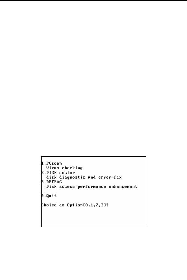
2.1.1Installation Program Guide
Executing g.bat file and the below screen will appear
Pressing any key and the below menu will occur
LNC Technology Co., Ltd. |
3 |
 LNC-M520 Series
Software Maintenance
Following is the introduction about the timing of these parameter before executing please refer to HOW2
1.First fully Total installation
This function is used for the first time fully installation and/or harddisk recovery. Generally speaking, LNC-520i is already installed into every LNC-520i series controller before going in the market. Therefore, unless the harddisk is “FORMATE”, there is no need to use this function.
Note1 To prepare a BOOTABLE H.D as C:DRIVE, please refer to the following:
a.Preparing a FORMATED HardDisk
b.Setting the BOOT SWQUENCE FOR the IPC BIOS As A: DRIVE first.
c.Putting the O.S UTILIT floppy disk into A: DRIVE (IBM PC DOS V7.0
d.Press CTRL+ALT+DEL or RESET to reboot the IPC from A: DRIVE
e.Please follow the instruction and execute [1] QUICK MAKE AN BOOTABLE H.D C
f.When the above are completed, please reboot the IPC and restore the PC BOOT SEQUENCE
as C ONLY.
Note2 The present DOS is IBM PC DOS 2000
2.Maintenance
User have 3 choices here:
1.PCScan Check out if there are viruses in the disk.
2.DISK Doctor Scan the disk and check the disk has been destroyed or not.
3.DEFRAG Defrag the disk.
4.Quit
Exit Installation windows and return to DOS system.
4 |
LNC Technology Co., Ltd. |
 LNC-M520 Series
Software Maintenance
2.1.2System Software Maintenance and Upgrade
For software update, users only need to follow the instruction to replace specific files with the newest files in the installation disk. Please make a copy of the prior version installation disk. Then, run [Gbat] to choose the correspondent function.
LNC Technology Co., Ltd. |
5 |

 LNC-M520 Series
Software Maintenance
2.2 SYSTEM DIRECTORIES
After executing LNC-M520i SERIES OS. Utility diskette, user will see below files:
2.2.1 |
[OS.UTILITY] |
|
|
|
|
|
|
|
|
Name |
Files |
|
|
|
|
|
|
C \DOS\ |
IBM PC_DOS 2000 |
|
|
C \ANTIVIR\ |
Anti-Virus |
|
|
C \MLC\ |
System LADDER Editing Software |
2.2.2 |
[LNC_M520i INSTALL DISK] |
|
|
|
|
|
|
|
|
Name |
Files |
|
|
|
|
|
|
C \LNCM520i\EXE |
System Files |
|
|
|
System program execute constant |
|
|
C \LNCM520i\RESOURCE |
resource file.(Please refer to DIR. DOC |
|
|
under menu. |
|
|
|
|
|
|
|
|
|
|
|
C \LNCM520i\MACHINE |
|
|
|
|
Standard milling canned cycle MACRO |
|
|
C \LNCM520i\MACRO |
program User NC program is NOT able |
|
|
|
to save in this menu. |
|
|
|
User NC working program |
|
|
C \LNCM520i\NCFILES |
File name must be restrictedto |
|
|
|
O0000~O8999 NC program |
|
|
|
CAM project document and other related |
|
|
C \LNCM520i\CAMPRJ |
files |
|
|
|
file sub-name is *.DAT |
6 |
LNC Technology Co., Ltd. |

|
|
|
LNC-M520 Series |
|
|
|
|
Hardware Maintenance |
|
3 |
Hardware Maintenance |
|
|
|
3.1 |
Specification |
|
|
|
Hardware Specification is as below |
|
|
||
|
|
|
|
|
|
|
LNC-520i |
Specification |
|
|
|
|
|
|
|
|
Display |
8.4 " colored TFT LCD "s |
|
|
|
|
|
|
|
|
Deposit and withdraw the storing device |
32M bytes or more |
|
|
|
dynamically ( DRAM RAM) |
|
|
|
|
Pair of CF card |
Every 32M bytes or more |
|
|
|
|
|
|
|
|
Soft disk drive interface and power |
Standard FDD; 5V/12V |
|
|
|
|
|
|
|
|
PC host computer board ( CPU BOARD) |
One grade of PC boards of industry |
|
|
|
|
|
|
|
|
Main shaft system |
Offer Pulse to control and export with DA |
|
|
|
|
|
|
|
|
Remote I/O (bunch arranges I/O) |
128 Input/128 Output |
|
|
|
|
|
|
|
|
USER I/O |
20 Input/16 Output |
|
|
|
|
|
|
|
|
Servo system |
Offer a return circuit / the speed return |
|
|
|
circuit of position to control |
|
|
|
|
|
|
|
|
|
The direct materials transmitting ( DNC) |
RS232 19200 Baud Rate |
|
|
|
|
|
|
|
|
Operation panel |
The standard milling machine uses the |
|
|
|
panel |
|
|
|
|
|
|
|
|
|
Handwheel interface |
Shut the wheel all alone three times |
|
|
|
|
|
|
|
|
The controlled axle counting |
4 axles |
|
|
|
|
|
|
|
|
The main shaft counting |
An axle |
|
|
|
|
|
|
|
|
Use the power |
(the first group power ) 12V (2A ) , 5V (6A ) |
|
|
|
" must use the supplying device of a pair of |
|
|
|
|
power " |
(the second group power ) 24V(4A) |
|
|
|
|
|
|
LNC Technology Co., Ltd. |
7 |

 LNC-M520 Series
Hardware Maintenance
LNC-520i Power Requirement
Power Type |
Specification |
Purpose |
Remark |
System Power (5V/12V - Must |
5V/ 6A and above |
For system sse. |
Must NOT lower |
|
|
|
than 4.8V |
|
12V/ 2A and above |
For system use. |
|
External Power (24V - Must |
24V/ 2A and above |
External I0 use. |
|
External Power (E5V |
5V/ 2A and above |
Linear Scale Power |
|
8 |
LNC Technology Co., Ltd. |

 LNC-M520 Series
Hardware Maintenance
3.1.1Connector Pin and Interface
|
|
|
|
|
|
|
|
|
|
|
|
|
FLOPPY |
|
FLOPPY |
|
|
|
|
|
|
|
|
|
|
|
|
|
|
|
POWER |
|
|
|
|
|
|
|
|
|
|
|
|
|
DA_VR 2 |
DA_VR 4 |
DA_VR 6 |
|
|
|
|
|
|
|
|
|
|
|
|
|
DA_VR 1 |
DA_VR 3 |
DA_VR 5 |
|
|
|
|
|
|
|
|
|
|
|
|
|
|
|
KB |
ENC5V FUSE |
24V FUSE |
OT FUSE |
5V FUSE |
|
|
|
|
|
|
|
|||||
DRIVE-PWD |
24V |
EGND |
FG |
12V GND |
5V |
FG |
|
|
|
|
|
|
|
||
|
|
|
|
|
|
|
|
LIO |
|
|
|
|
|
|
|
|
NPN PNP |
|
COMSV |
X SV |
4 SV Z SV Y SV |
|
|
|
|
|
|
|
|
||
|
|
|
|
|
|
|
|
|
|
|
|
||||
|
|
|
|
|
|
|
|
RIO |
USER I/O |
Z |
AXIS |
X |
AXIS |
|
|
|
OT1 |
OT2 |
|
24V |
HS1 |
24V |
HS2 |
|
|
|
|
|
|
|
|
EGND ENC5V |
24V |
EGND |
|
24V |
HS3 |
24V |
HS4 |
MPG |
SP AXIS |
4th |
AXIS |
Y |
AXIS |
|
|
Back of Controller
LNC Technology Co., Ltd. |
9 |

 LNC-M520 Series
Hardware Maintenance
|
|
○9 |
|
|
|
|
○12 |
○11 |
○10 |
|
|
|
|
○15 |
○14 |
○13 |
○7 |
○5 |
○3 |
○1 |
|
|
|
|
|||
○18 |
|
○16 |
○8 |
○6 |
○4 |
○2 |
|
|
|
|
|
||
|
|
# Indication |
|
To |
Connector Type/Remark |
|
1 |
|
X AXIS |
|
X Axis Servo |
25 PIN Connector (Female |
|
2 |
|
Y AXIS |
|
Y Axis Servo |
25 PIN Connector (Female |
|
3 |
|
Z AXIS |
|
Z Axis Servo |
25 PIN Connector (Female |
|
4 |
|
4th AXIS |
|
4th Axis Servo |
25 PIN Connector (Female |
|
6 |
|
SP AXIS |
|
Spindle |
25 PIN Connector (Female |
|
5 |
|
USER I/O |
|
REL2840 |
44 PIN High-Density |
|
|
|
Connector (Male |
||||
|
|
|
|
|
||
7 |
|
RIO |
|
SIO Card |
15 PIN Connector |
(Male |
8 |
|
MPG |
|
3 In 1 MPG |
15 PIN Connector (Female |
|
9 |
ENC5V 24V 12V 5V FUSE |
N/A |
Power |
|
||
10 |
|
12V GND 5V FG |
12V 5V Power Supply |
System Power |
||
11 |
|
24V EGND FG |
Outer 24V Power Supply |
IO Power |
|
|
18 |
|
EGND ENC5V |
Outer 5V Power Supply |
Linear Scale Power |
||
17 |
|
SVI-COM 24V EGND |
N/A |
Switch to Servo COM Point |
||
14 |
|
OT |
|
Connection Point |
Hardware Protected |
|
|
|
Overtravel Connector Point |
||||
|
|
|
|
|
||
12 |
|
DRIVER_POWER |
Empty Connection Point |
Controlable Servo Power |
||
13 16 |
|
HS1~HS4 |
|
HOME Point SENSOR |
Return HOME SENSOR |
|
|
|
KB |
|
Keyboard |
|
|
|
|
FLOPPY |
|
Floppy Diskette |
|
|
|
|
FLOPPY POWER |
Floppy Driver Power |
|
|
|
|
|
Connector |
|
|
||
|
|
|
|
|
|
|
|
|
CF1 |
|
CF Card 1 |
CF Card |
|
|
|
CF2 |
|
CF Card 2 |
BackUP CF Card |
|
10 |
LNC Technology Co., Ltd. |

 LNC-M520 Series
Hardware Maintenance
|
|
B |
|
C |
|
○15 |
|
|
|
|
|
||
|
|
|
|
|
|
|
|
|
|
|
|
||
A |
|
|
|
|
D |
|
|
|
|
|
|
|
|
|
|
|
|
|
|
|
|
|
F |
|
|
|
|
LNC Technology Co., Ltd. |
11 |

 LNC-M520 Series
Hardware Maintenance
|
Code Display Function at Back of LNC-520i |
|
Code |
|
Corresponding Conditioin |
|
|
|
A |
|
Light ON when Internal PULSE/ENCODER 5V Normal |
|
|
|
B |
|
Light ON when Servo ON |
|
|
|
C |
|
Light ON when Servo Reset |
|
|
|
D |
|
Light ON when Outer 24V Power is Entered |
|
|
|
F |
|
Light ON when NOT OT(When OT1 & OT2 are short |
|
circuit |
|
|
|
|
12 |
LNC Technology Co., Ltd. |

 LNC-M520 Series
Hardware Maintenance
3.1.2LNC-520i Controller Wiring Chart
W11 |
FDD |
|
|
|
|
Keyboard |
12V 5V Power Spindle |
|
|
W6 |
MPG |
|
|
|
||
|
|
|
W1 |
|
|
|
|
W2 |
X Axis Motor |
|
W8 |
|
W3 |
Y Axis Motor |
24V Power |
|
|
||
|
|
W4 |
|
|
|
|
|
Z Axis Motor |
|
|
|
|
|
|
|
|
|
|
4 Axis Motor |
|
|
|
W5 |
Spindle Motor |
|
|
|
|
|
|
|
|
Spindle Inventor |
|
|
W7 |
W9 |
REL2840 |
|
|
|
|
|
|
|
|
W10 |
REL2840 |
|
|
Signal Cable |
SIO1540 |
|
|
Power Supply Cable
LNC Technology Co., Ltd. |
13 |

 LNC-M520 Series
Hardware Maintenance
System Cable Table
|
Motion Control Part |
|
|
|
|||
# |
Specification |
|
|
|
|
Remark |
|
W1~W5 |
D_SUB25PIN(Male -- Servo (Inventor) Connector |
Please |
refer |
to |
Appendix: Wiring |
||
|
|
|
|
Example |
|
|
|
W6 |
D_SUB15PIN(Male -- MPG |
|
|
Please |
refer |
to |
Appendix: Wiring |
|
|
|
|
Example |
|
|
|
|
|
IO Part |
|
|
|
|
|
# |
Specification |
|
|
Remark |
|||
W7 |
D_SUB15PIN (Female -- D_SUB15PIN HD (Male |
One to one connect |
|||||
|
|
|
|
|
SIO1540 |
|
|
W7 |
D_SUB15PIN (Female -- D_SUB15PIN (Female |
One to one connect |
|||||
|
|
|
|
|
SIO1520 |
|
|
W8 |
D_SUB44PIN HD (Male -- D_SUB44PIN HD (Female |
One to one connect |
|||||
W9 |
D_SUB44PIN HD (Male -- D_SUB44PIN HD (Male |
One to one connect |
|||||
W10 |
D_SUB44PIN HD (Male --D_SUB44PIN HD (Female |
One to one connect |
|||||
|
|
|
|
|
|
||
|
System Perhiperal Part |
|
|
|
|||
# |
Specification |
|
Remark |
|
|
|
|
W11 |
2.54mm34PIN Flat Cable |
|
A Drive Floppy Cable |
|
|
|
|
14 |
LNC Technology Co., Ltd. |
 LNC-M520 Series
Hardware Maintenance
3.1.3Connector Pin Definition
X Y Z 4 Connector Pin Chart
13 |
|
|
25 |
E/B |
|
12 |
||
EB |
||
24 |
||
E/A |
||
11 |
||
EA |
||
23 |
||
E/C |
||
10 |
||
EC |
||
22 |
||
|
||
9 |
SRV_RESET |
|
21 |
||
|
||
8 |
|
|
20 |
SVI_COM |
|
7 |
||
|
||
19 |
ALARM |
|
6 |
||
SRVON |
||
18 |
||
+24V |
||
5 |
||
|
||
17 |
DACO |
|
4 |
||
|
||
16 |
|
|
3 |
ENCE5V |
|
15 |
||
PA |
||
2 |
||
PB |
||
14 |
||
/PA |
||
1 |
||
/PB |
||
|
PIN |
Name |
Description |
PIN |
Name |
Description |
|
|
|
|
|
|
|
|
1 |
/PB |
PULSE Output B Reverse |
14 |
/PA |
PULSE Output A |
|
Phase |
Reverse Phase |
|||||
|
|
|
|
|||
2 |
PB |
PULSE Output B Phase |
15 |
PA |
PULSE Output A |
|
Phase |
||||||
|
|
|
|
|
||
3 |
ENCE5V |
Linear Scale Outer 5V |
16 |
- |
- |
|
|
|
|
|
|
|
|
4 |
EGND |
24V Power Ground |
17 |
daco |
Analogy Voltage |
|
Output |
||||||
|
|
|
|
|
||
5 |
AGND |
Analogy Output Ground |
18 |
+24V |
Outer Power 24V |
|
|
|
|
|
|
|
|
6 |
SRV-ON |
Servo Ready Output |
19 |
ALARM |
Servo Alarm |
|
|
|
|
|
|
|
|
7 |
EGND |
Outer Power Ground |
20 |
SVI_COM |
Servo COM Point |
|
(ENC5V 24V |
Setting |
|||||
|
|
|
|
|||
8 |
SVI_COM |
Servo COM Point Setting |
21 |
EGND |
Outer Power Ground |
|
|
|
|
|
|
|
|
9 |
SRV_RST |
Servo Reset Signal |
22 |
- |
- |
|
|
|
|
|
|
|
|
10 |
EC |
Encoder C Phase |
23 |
E/C |
Encoder C Reverse |
|
Phase |
||||||
|
|
|
|
|
||
11 |
EA |
Encoder A Phase |
24 |
E/A |
Encoder A Reverse |
|
Phase |
||||||
|
|
|
|
|
||
12 |
EB |
Encoder B Phase |
25 |
E/B |
Encoder B Reverse |
|
Phase |
||||||
|
|
|
|
|
||
13 |
FG |
Outer Ground |
- |
- |
- |
|
|
|
|
|
|
|
LNC Technology Co., Ltd. |
15 |

 LNC-M520 Series
Hardware Maintenance
SP Connector PIN Chart
13 |
|
|
25 |
E/B |
|
12 |
||
EB |
||
24 |
||
E/A |
||
11 |
||
EA |
||
23 |
||
E/C |
||
10 |
||
EC |
||
22 |
||
|
||
9 |
SRV_RST |
|
21 |
||
|
||
8 |
|
|
20 |
SVI_COM |
|
7 |
||
|
||
19 |
ALRAM |
|
6 |
SRV_ON |
|
18 |
||
+24V |
||
5 |
||
|
||
17 |
DAC_OUT |
|
4 |
||
|
||
16 |
|
|
3 |
E5V |
|
15 |
||
PA |
||
2 |
||
PB |
||
14 |
||
/PA |
||
1 |
||
/PB |
||
|
PIN |
Name |
Description |
PIN |
Name |
Description |
|||
|
|
|
|
|
|
|||
1 |
/PB |
PULSE Output B Reverse |
14 |
/PA |
PULSE Output A Reverse |
|||
Phase |
Phase |
|
|
|||||
|
|
|
|
|
|
|||
2 |
PB |
PULSE Output B Phase |
15 |
PA |
PULSE Output A Phase |
|||
|
|
|
|
|
|
|
|
|
3 |
ENCE5V |
Linear Scale Outer 5V |
16 |
- |
- |
|
|
|
|
|
|
|
|
|
|||
4 |
EGND |
24V Power Ground |
17 |
daco |
Analogy Voltage Output |
|||
|
|
|
|
|
|
|
||
5 |
AGND |
Analogy Output Ground |
18 |
+24V |
Outer Power 24V |
|
||
|
|
|
|
|
|
|
|
|
6 |
SRV-ON |
Servo Ready Output |
19 |
ALARM |
Servo Alarm |
|
|
|
|
|
|
|
|
|
|
|
|
7 |
EGND |
Outer Power Ground |
20 |
SVI_COM |
Servo COM Point Setting |
|||
(ENC5V 24V |
||||||||
|
|
|
|
|
|
|
||
8 |
SVI_COM |
Servo COM Point Setting |
21 |
EGND |
Outer Power Ground |
|||
|
|
|
|
|
|
|
|
|
9 |
SRV_RST |
Servo Reset Signal |
22 |
- |
- |
|
|
|
|
|
|
|
|
|
|
|
|
10 |
EC |
Encoder C Phase |
23 |
E/C |
Encoder |
C |
Reverse |
|
Phase |
|
|
||||||
|
|
|
|
|
|
|
||
11 |
EA |
Encoder A Phase |
24 |
E/A |
Encoder A Reverse Phase |
|||
|
|
|
|
|
|
|
|
|
12 |
EB |
Encoder B Phase |
25 |
E/B |
Encoder |
B |
Reverse |
|
Phase |
|
|
||||||
|
|
|
|
|
|
|
||
13 |
FG |
Outer Ground |
- |
- |
- |
|
|
|
|
|
|
|
|
|
|
|
|
16 |
LNC Technology Co., Ltd. |
 LNC-M520 Series
Hardware Maintenance
MPG Connector PIN
|
E5V |
|
8 |
|
|
15 |
|
|
7 |
MPGX |
|
14 |
||
MPGY |
||
6 |
||
MPGZ |
||
13 |
||
X10 |
||
5 |
||
X100 |
||
12 |
||
EA |
||
4 |
||
E/A |
||
11 |
||
EB |
||
3 |
||
E/B |
||
10 |
||
|
||
2 |
MPG4 |
|
9 |
||
|
||
1 |
+24V |
|
|
PIN |
Name |
Description |
PIN |
Name |
Description |
|
|
|
|
|
|
|
|
1 |
+24V |
Outer Power 24V |
9 |
EGND |
Outer Power Ground |
|
|
|
|
|
|
|
|
2 |
MPG4 |
MPG-4 |
10 |
FG |
Outer Ground |
|
|
|
|
|
|
|
|
3 |
E/B |
Encoder B Reverse |
11 |
EB |
Encoder B Phase |
|
Phase |
||||||
|
|
|
|
|
||
4 |
E/A |
Encoder A Reverse Phase |
12 |
EA |
Encoder A Phase |
|
|
|
|
|
|
|
|
5 |
X100 |
MPG Ratio 100 |
13 |
X10 |
MPG Ratio 10 |
|
|
|
|
|
|
|
|
6 |
MPGZ |
MPG-Z |
14 |
MPGY |
MPG-Y |
|
|
|
|
|
|
|
|
7 |
MPGX |
MPG-X |
15 |
E5V |
Outer Power 5V |
|
|
|
|
|
|
|
|
8 |
E5V |
Outer Power 5V |
- |
- |
- |
|
|
|
|
|
|
|
LNC Technology Co., Ltd. |
17 |

 LNC-M520 Series
Hardware Maintenance
Remote Control Connector PIN Chart
/G1SCS2 G1SCS2
 /G1SDI
 G1SDI
G1SDI
G1SDO  /G1SDO
  /G1SCS1
G1SCS1 
/G1SCS0 G1SCS0
/G1SIOCLK
G1SIOCLK
VCC
8 

15
7
14
6
13
5
12
4
11
3
10
2
9
1
18 |
LNC Technology Co., Ltd. |
 LNC-M520 Series
Hardware Maintenance
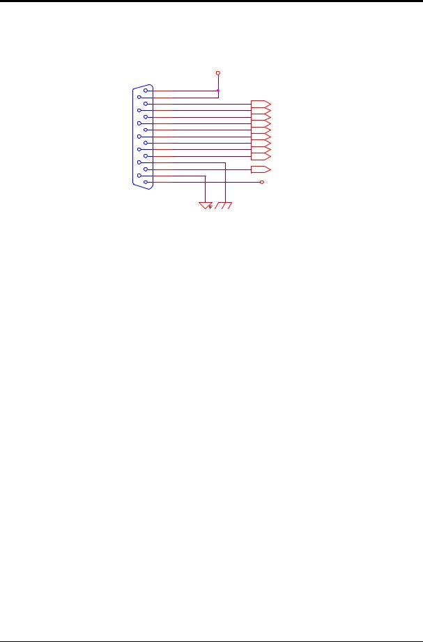
USE_IN0 USE_IN3
 USE_IN6
 USE_IN9
 USE_IN12 USE_IN15 USE_IN18
OP0 OP3 OP6 OP9 OP12 OP15
USE_IN1 USE_IN4
 USE_IN7
 USE_IN10 USE_IN13 USE_IN16 USE_IN19
USER I/O Connector PIN Chart
|
|
|
|
|
|
|
+24V |
||
1 |
|
|
44 |
|
|
|
|
|
|
1 |
44 |
|
|
|
|
|
|
||
2 |
43 |
|
|
|
|
|
|
||
2 |
43 |
|
|
|
|
|
|
||
3 |
42 |
|
|
|
|
|
|
||
3 |
42 |
|
|
|
|
|
|
||
4 |
41 |
|
|
|
|
|
OP14 |
||
5 |
4 |
41 |
40 |
|
|
|
|
|
|
|
5 |
40 |
|
|
|
|
|
|
OP11 |
6 |
6 |
39 |
39 |
|
|
|
|
|
OP8 |
7 |
38 |
|
|
|
|
|
|||
8 |
7 |
38 |
37 |
|
|
|
|
|
OP5 |
9 |
8 |
37 |
36 |
|
|
|
|
|
OP2 |
|
9 |
36 |
|
|
|
|
|
|
USE_IN17 |
10 |
10 |
35 |
35 |
|
|
|
|
|
USE_IN14 |
11 |
34 |
|
|
|
|
|
|||
12 |
11 |
34 |
33 |
|
|
|
|
|
USE_IN11 |
13 |
12 |
33 |
32 |
|
|
|
|
|
USE_IN8 |
|
13 |
32 |
|
|
|
|
|
|
USE_IN5 |
14 |
14 |
31 |
31 |
|
|
|
|
|
USE_IN2 |
15 |
30 |
|
|
|
|
|
|||
16 |
15 |
30 |
29 |
|
|
|
|
|
|
16 |
29 |
|
|
|
|
|
|
||
17 |
28 |
|
|
|
|
|
|
||
17 |
28 |
|
|
|
|
|
|
||
18 |
27 |
|
|
|
|
|
OP13 |
||
19 |
18 |
27 |
26 |
|
|
|
|
|
|
20 |
19 |
26 |
25 |
|
|
|
|
|
OP10 |
21 |
20 |
25 |
24 |
|
|
|
|
|
OP7 |
|
21 |
24 |
|
|
|
|
|
|
OP4 |
22 |
22 |
23 |
23 |
|
|
|
|
|
OP1 |
|
|
|
|
|
|
|
|||
|
|
|
|
|
|
|
|
|
|
PIN |
Definition |
PIN |
Definition |
PIN |
Definition |
|
|
|
|
|
|
1 |
IN0 |
16 |
IN1 |
31 |
IN2 |
|
|
|
|
|
|
2 |
IN3 |
17 |
IN4 |
32 |
IN5 |
|
|
|
|
|
|
3 |
IN6 |
18 |
IN7 |
33 |
IN8 |
|
|
|
|
|
|
4 |
IN9 |
19 |
IN10 |
34 |
IN11 |
|
|
|
|
|
|
5 |
IN12 |
20 |
IN13 |
35 |
IN14 |
|
|
|
|
|
|
6 |
IN15 |
21 |
IN16 |
36 |
IN17 |
|
|
|
|
|
|
7 |
IN18 |
22 |
IN19 |
37 |
OUT2 |
|
|
|
|
|
|
8 |
OUT0 |
23 |
OUT1 |
38 |
OUT5 |
|
|
|
|
|
|
9 |
OUT3 |
24 |
OUT4 |
39 |
OUT8 |
|
|
|
|
|
|
10 |
OUT6 |
25 |
OUT7 |
40 |
OUT11 |
|
|
|
|
|
|
11 |
OUT9 |
26 |
OUT10 |
41 |
OUT14 |
|
|
|
|
|
|
12 |
OUT12 |
27 |
OUT13 |
42 |
- |
|
|
|
|
|
|
13 |
OUT15 |
28 |
- |
43 |
+24V |
|
|
|
|
|
|
14 |
- |
29 |
- |
44 |
+24V |
|
|
|
|
|
|
15 |
EGND 24V |
30 |
EGND 24V |
- |
- |
|
GND |
|
GND |
|
|
LNC Technology Co., Ltd. |
19 |

 LNC-M520 Series
Hardware Maintenance
3.1.4Description of Interface Using
3.1.4.1OT Connector Point and DRIVER POWER Connector Power
OTConnecto OT1
EMG1
POWER DRIVE
POWER
Connect
+24V
2
1
OT_RELEASE |
SVRON |
SVI_COM |
2
1
2
1
OT & DRIV_PWD Connector Wiring
Just like the above figure show, OT and EMG connecting point must be in short circuit condition when enable servo. So, OT Connector component must be the NC point. Moreover, if using multiple OP component, please use local connecting. Also, servo enabling signal can be switched by SW of SVI_CO. Furthermore, this control provides a empty connecting point which is used for DRIVER Power and the capacity of that is 5A.
3.1.4.2Home Point Checking Connecting Point
|
|
+24V |
|
1 |
HS1 |
HOME 1 |
2 |
|
3 |
HS2 |
|
|
4 |
|
|
1 |
HS3 |
HOME 2 |
2 |
|
3 |
HS4 |
|
|
4 |
20 |
LNC Technology Co., Ltd. |

 LNC-M520 Series
Hardware Maintenance
This above figure is the Zero Point checint interface chart. Please notice that controller will receive signal when HS1~HS4 has 24V input each. User can adding a connecting point between 24V and HS. Or, using an Output 24V SENSOR (need to use with IO 24VPower ground) as zero point checking component.
LNC Technology Co., Ltd. |
21 |

 LNC-M520 Series
Hardware Maintenance
3.1.5I/O Corresponding Table
I0 |
EDIT |
|
O0 |
EDIT |
LIGHT |
|
||
I01 |
MEM |
|
O1 |
MEM |
LIGHT |
|
||
I02 |
MDI |
|
O2 |
MDI |
LIGHT |
|
|
|
I03 |
JOG |
|
O3 |
JOG |
LIGHT |
|
|
|
I04 |
MPG |
|
O4 |
MPG |
LIGHT |
|
||
I05 |
ZRN |
|
O5 |
ZRN |
LIGHT |
|
|
|
I06 |
RAPID |
|
O6 |
RAPID LIGHT |
|
|||
I07 |
SPINDLE |
CW |
O7 |
SPINDLE |
CW |
LIGHT |
||
I08 |
SPINDLE |
STOP |
O8 |
SPINDLE |
STOP |
LIGHT |
||
I09 |
SPINDLE |
CCW |
O9 |
SPINDLE |
CCW |
LIGHT |
||
I10 |
+X AXIS |
PB |
O10 |
+X AXIS |
PB |
LIGHT |
||
I11 |
-X AXIS |
PB |
O11 |
-X AXIS |
PB |
LIGHT |
||
I12 |
+Y AXIS |
PB |
O12 |
+Y AXIS |
PB |
LIGHT |
||
I13 |
-Y AXIS |
PB |
O13 |
-Y AXIS |
PB |
LIGHT |
||
I14 |
+Z AXIS |
PB |
O14 |
+Z AXIS |
PB |
LIGHT |
||
I15 |
-Z AXIS |
PB |
O15 |
-Z AXIS |
PB |
LIGHT |
||
I16 |
+4 AXIS |
PB |
O16 |
+4 AXIS |
PB |
LIGHT |
||
I17 |
-4AXIS PB |
O17 |
-4AXIS PB |
LIGHT |
||||
I18 |
MAGAZINE CW |
O18 |
MAGAZINE CW LIGHT |
|||||
I19 |
MAGAZINE CCW |
O19 |
MAGAZINE CCW LIGHT |
|||||
I20 |
ORI |
|
O20 |
ORI |
|
|
|
|
I21 |
COOLANT ON |
O21 |
COOLANT ON LIGHT |
|||||
I22 |
WORK LIGHT |
O22 |
WORK LIGHT |
|
||||
I23 |
AIR BLOW |
O23 |
AIR BLOW LIGHT |
|||||
I24 |
(F1 |
|
O24 |
F1 LIGHT |
|
|
||
I25 |
(F2 |
|
O25 |
F2 LIGHT |
|
|
||
I26 |
(F3 |
|
O26 |
F3 LIGHT |
|
|
||
I27 |
(F4 |
|
O27 |
F4 LIGHT |
|
|||
I28 |
SINGLE BLOCK |
O28 |
SINGLE BLOCK LIGHT |
|||||
I29 |
CYCLE START |
O29 |
CYCLE START LIGHT |
|||||
I30 |
FEED HOLD |
O30 |
FEED HOLD LIGHT |
|||||
I31 |
EMERGENCY |
O31 |
NC READY |
|
|
|||
I32 |
MPG SELECT X |
O32 |
ALARM |
|
|
|
||
I33 |
MPG SELECT Y |
O33 |
HOME LIGHT |
|
||||
I34 |
MPG SELECT Z |
O34 |
S + |
|
|
|
|
|
I35 |
MPG SELECT 4 |
O35 |
S - |
|
|
|
|
|
I36 |
MPG *10 |
|
O36 |
F + |
|
|
|
|
I37 |
MPG *100 |
O37 |
F - |
|
|
|
|
|
I38 |
ALARM 1 |
|
O38 |
OT RELEASE LIGHT |
||||
I39 |
ALARM 2 |
|
O39 |
FRV-RESET |
|
|
||
22 |
LNC Technology Co., Ltd. |

 LNC-M520 Series
Hardware Maintenance
3.2 I/O card SIO 1520
Besides to 20 Input/16 Output, I/O module of this system can be extended to 128 Input/128 Output at most. Connecting chart shows as below:
Slave I/O board provides Jumper selection for two output signal methods. One is Source type and the other one is Sink type. The output voltage is 24V and every point’s maximum pushing function is 80mA. To determine input signal, the determination for High (1) is 15 ~ 28V, the determination for Low (0) is 0 ~ 4V and the input voltage is 10mA. The JPI on the SLAVE mothor board will connect DC24V power from outside.
LNC Technology Co., Ltd. |
23 |

 LNC-M520 Series
Hardware Maintenance
3.2.1I/O Card Specification
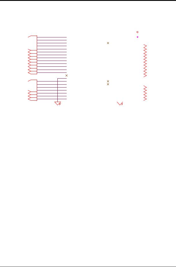
To reduce IO cable, we can complete I/O transmission by motion control card with I/O card. An I/O card can be divided to SIO 1520 master board or S1O 1540 master board and SIO 1530 slave board.
One SIO card can offer 40 input and 32 output, and SIO 1530 extension cardcan offer 24 input and 32 output; in the other word, 1 set of I/O master board and slave board can offfer 64 input and 64 output totally. LNC 600 can string up 2 set of SIO master board +SIO slave board by using RIO connecter, so it can offer 128 input and 128 output at most.
•SIO master board 1 SIO1520
SIO1520
|
|
|
|
|
|
|
|
|
|
|
|
|
|
|
|
|
|
|
|
24 |
|
|
|
LNC Technology Co., Ltd. |
 Loading...