

Page 1
LNC-M650
O
O
p
p
err
e
att
a
orr’’
o
Leading Numerical Controller
s
s
2011/05 Ver:V04.00.000(4408210117)
M
M
a
a
n
n
u
u
all
a
LNC Technology Co., Ltd.
LNC Technology Co., Ltd. 1
Page 2

Page 3

LNC-M650
Table of Content
Table of Content
1 PREFACE................................................................................................ 1
2 CNC OPERATION................................................................................... 1
2.1 OPERATION DEVICES TYPE ................................................................................. 1
2.1.1 LCD Display Device .............................................................................. 2
2.1.2 MDI........................................................................................................ 3
2.2 OPERATION DEVICE INTRODUCTION ..................................................................... 4
2.3 SCREEN AND FUNCTION DESCRIPTION ............................................................... 10
2.3.1 Display Screen Layout ........................................................................ 10
2.3.2 Function Group Figure .........................................................................11
2.4 POS FUNCTION ............................................................................................... 22
2.4.1 ABSOLUTE COORDINATE ................................................................ 23
2.4.2 RELATIVE COORDINATE................................................................... 24
2.4.3 MACHINERY COORDINATE .............................................................. 25
2.4.4 MEA (Measure) ................................................................................... 26
2.4.5 EXIT .................................................................................................... 27
2.5 PROG ............................................................................................................ 28
2.5.1 FGPROG............................................................................................. 29
2.5.2 BGPROG (Background Program) ....................................................... 35
2.5.3 DIRMNG (File Management)............................................................... 36
2.5.4 PROCHK (Program Checking)............................................................ 42
2.5.5 MDI...................................................................................................... 43
2.5.6 COMM (Communication of Files(RS232)) ...................................... 44
2.5.7 DNC Function...................................................................................... 49
2.6 OFFSET......................................................................................................... 50
2.6.1 TOOL OFFSET ................................................................................... 50
2.6.2 MACRO............................................................................................... 51
2.6.3 WORK ................................................................................................. 53
2.7 MILLING EASY-CAM........................................................................................ 55
2.7.1 Preface................................................................................................ 55
2.7.2 Function Specification ......................................................................... 55
2.7.3 CUT PAR (Cutting Parameter) ............................................................ 56
2.7.4 Screen Operation Description ............................................................. 58
2.8 MILLING FIGURE CONVERSATION ............................................................. 62
2.8.1 PREFACE ........................................................................................... 62
LNC Technology Co., Ltd. I
Page 4

LNC-M650
Table of Content
2.8.2 Function Specification ......................................................................... 62
2.8.3 Work Production Selection .................................................................. 63
2.8.4 Common Parameters Setting .............................................................. 66
2.8.5 Cutting Parameter Setting ................................................................... 66
2.8.6 Operation Screen Description ............................................................. 67
2.9 GRAPH .......................................................................................................... 72
2.9.1 Function Introduction........................................................................... 72
2.9.2 GRAPH ............................................................................................... 72
2.9.3 SET ..................................................................................................... 73
2.10 DGNOS.......................................................................................................... 75
2.10.1 ALARM................................................................................................ 75
2.10.2 IOCSA................................................................................................. 78
2.10.3 PLC2 ................................................................................................... 79
2.10.4 SYSTEM ............................................................................................. 80
2.10.5 Working Parameter Page .................................................................... 83
2.10.6 SYSUPD ............................................................................................. 84
2.10.7 CIRCUL............................................................................................... 92
2.11 SOFTPL......................................................................................................... 94
2.12 PARAM .......................................................................................................... 96
2.12.1 NC. SYS.............................................................................................. 96
2.12.2 USROPT (Users Parameter) ............................................................... 99
2.12.3 LNCS................................................................................................. 100
2.13 RESET......................................................................................................... 103
3 OP PANEL OPERATION..................................................................... 105
3.1 O
3.2 POWER SWITCH (ON/OFF)............................................................................. 106
3.3 EMG-STOP KEY........................................................................................... 106
3.4 CYCLE START............................................................................................. 107
3.5 FEED HOLD................................................................................................. 108
3.6 LED SIGNAL ................................................................................................ 109
PERATION PANEL ......................................................................................... 105
3.6.1 Original OP........................................................................................ 109
3.6.2 OP2520 ............................................................................................. 109
3.7 MODE SELECT ............................................................................................110
3.8 AXIS SELECTION.........................................................................................112
3.9 SPINDLE ROTATION....................................................................................113
3.10 OT RELEASE................................................................................................114
3.11 COOLANT SUPPLY......................................................................................115
II
LNC Technology Co., Ltd.
Page 5

Table of Content
3.11.1 Original OP.........................................................................................115
3.11.2 OP2520 ..............................................................................................115
3.12 TOOL MAGAZINE.........................................................................................116
3.13 SINGLE BLOCK STOP .......................................................................................116
3.14 ADDITIONAL FUNCTION SELECTION ...................................................................117
3.15 FEEDRATE / RAPID RATE ADJUSTING BUTTON ....................................................118
3.16 SPINDLE SPEED ADJUSTMENT SWITCH ..................................................119
LNC-M650
LNC Technology Co., Ltd. III
Page 6

LNC-M650
Preface
1 Preface
LNC-M650 Series is a standard DOS-Based controller and also an integrated and
economical numerical controller product which is designed by LNC Technology. Its stability
in quality is best suitable for applications of middle complexity, such as milling, grinding
and all other kinds of industrial and automatically tools.
This controller did not have 5 axes shape control and cutting function, only suitable for
industrial machines.
This controller did not have 5 axes TCP tool tip compensation functions.
This controller did not have rotation axes speed planning function.
This controller did not have 5 axes machining center interference anti-collision check
function.
2 CNC Operation
2.1 Operation Devices Type
The control panels can be divided into two units: MDI and OP. The MDI is used to edit part
programs as well as to enter relevant working data. The OP (Operation Panel), on the
other hand, is used to manipulate operational conditions. There are multiple function keys,
keys and pulse generator (hand wheel) and etc. OP will have different designs due to
different tool machine designs. But, this system has one standard panel that can be
selected by tool machine producers. MDI will be introduced in the following. OP and its
functions will be introduced in Chapter Three.
LNC Technology Co., Ltd. 1
Page 7
LNC-M650
CNC Operation
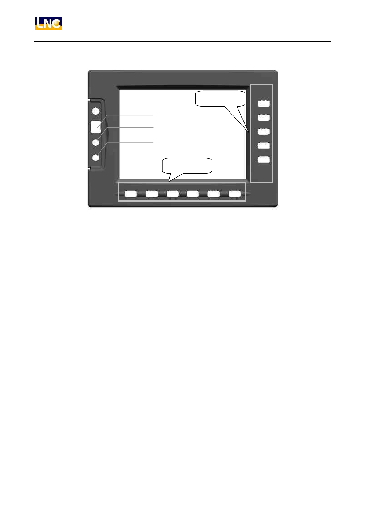
2.1.1 LCD Display Device
Sub
LCD Switches
PS/2 Keyboard
PS/2 Mouse
Main
Figure 2.1-1 LCD Display Device
2
LNC Technology Co., Ltd.
Page 8
LNC-M650
CNC Operation
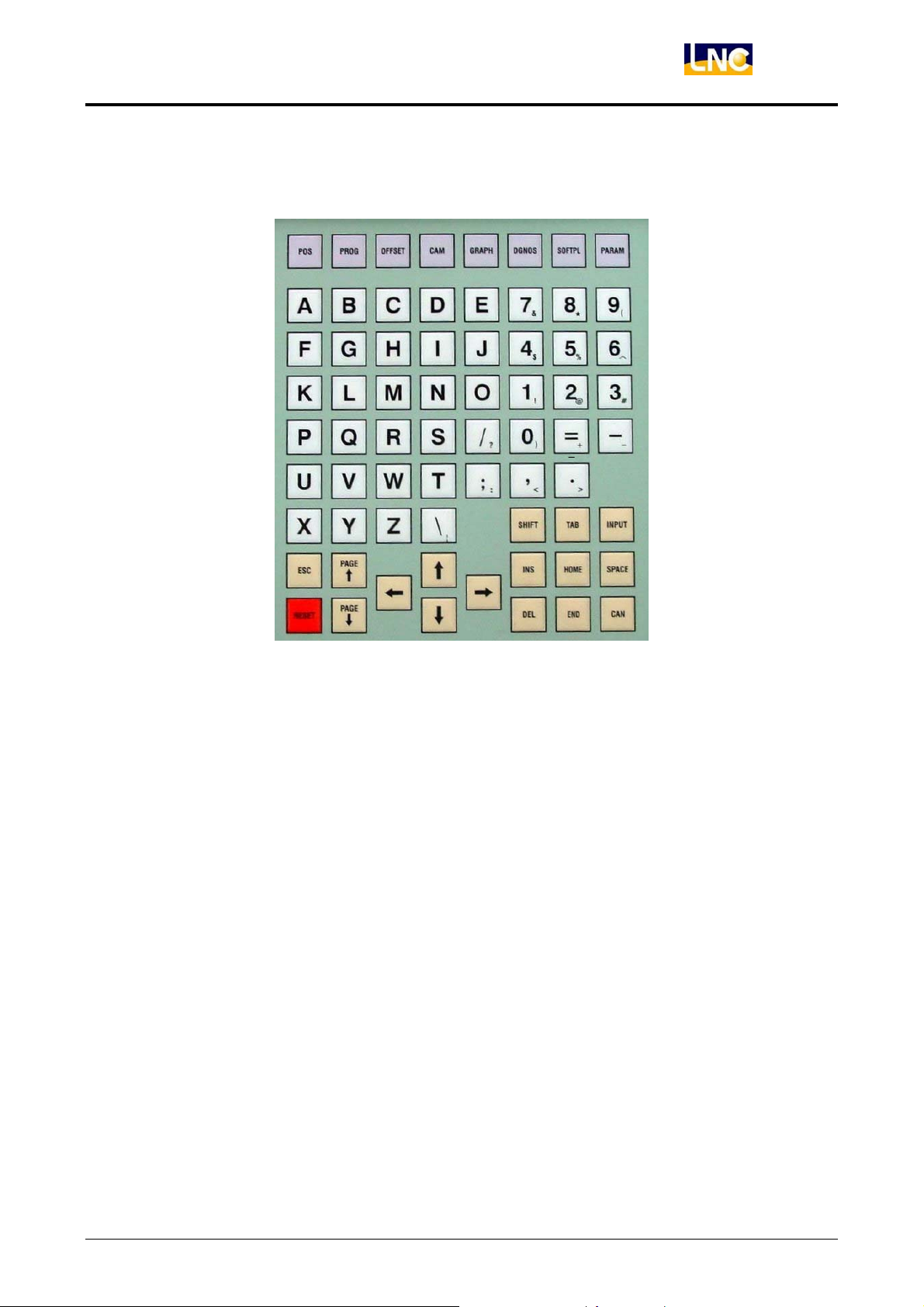
2.1.2 MDI
Figure 2.1-2 MDI
LNC Technology Co., Ltd. 3
Page 9
LNC-M650
CNC Operation
2.2 Operation Device Introduction
The following will introduce 4 types of function keys, based on their function, on MDI panel
for LCD display device only:
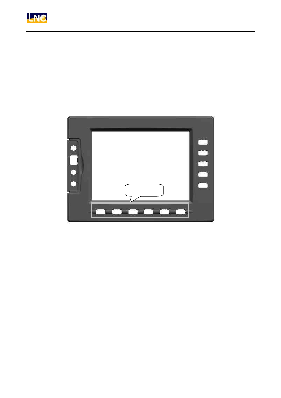
(1) Main Function Keys:
There are 6 horizontal function buttons at bottom of LCD screen. Users can choose
the desired function button corresponding to those function selections at bottom of
the display screen by press them.
Main
Figure 2.2-1 6 Main Function Keys at Bottom of Screen
4
LNC Technology Co., Ltd.
Page 10
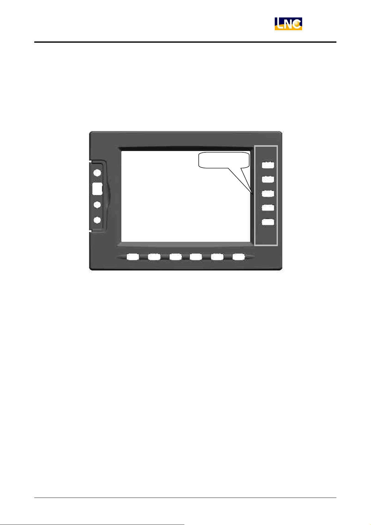
(2) Sub-Function Keys:
After choosing the main function button, the content of sub-function will occur at
right side of the screen. Pressing the corresponding function button to select the
wanted function. Left diagram shows the sub-function content of the corresponding
coordinate (main function buttons). Selecting any one function, the screen will
display the last chosen screen.
LNC-M650
CNC Operation
Sub
Figure 2.2-2 5 Sub-Function Keys on the Right of the Screen
LNC Technology Co., Ltd. 5
Page 11
LNC-M650
CNC Operation
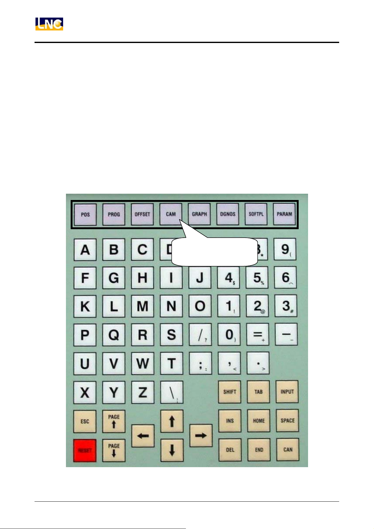
(3) Function Group Selection Keys:
To select 8 functions such are POS, PROG, OFFSET, CAM, GRAPH, DGNOS,
SOFTPL and PARAM.
<POS> :to display positions
<PROG> :to edit and to display program
<OFFSET>:to set and to display tool offsest
<CAM> :to edit working program by Figure method
<GRAPH> :to draw tool path
<DGNOS> :to display instance messge at DGNOS page
<SOFTPL>: to select software panel switches
<PARAM> :to display parameter screen
Group Function Keys
6
LNC Technology Co., Ltd.
Page 12
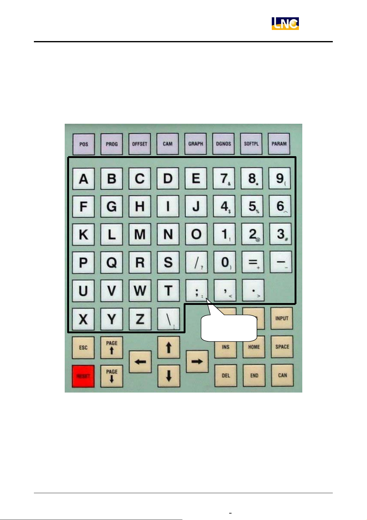
(4) Character & Symbol Keys:
These characters, symbols and numbers are used for program editing and data
key-in. There are some symbols that are diminished down at right-bottom of these
keys. If want to use these symbols, please press SHIFT and the symbol key at the
same time.
LNC-M650
CNC Operation
Symbol Keys
LNC Technology Co., Ltd. 7
Page 13

LNC-M650
CNC Operation
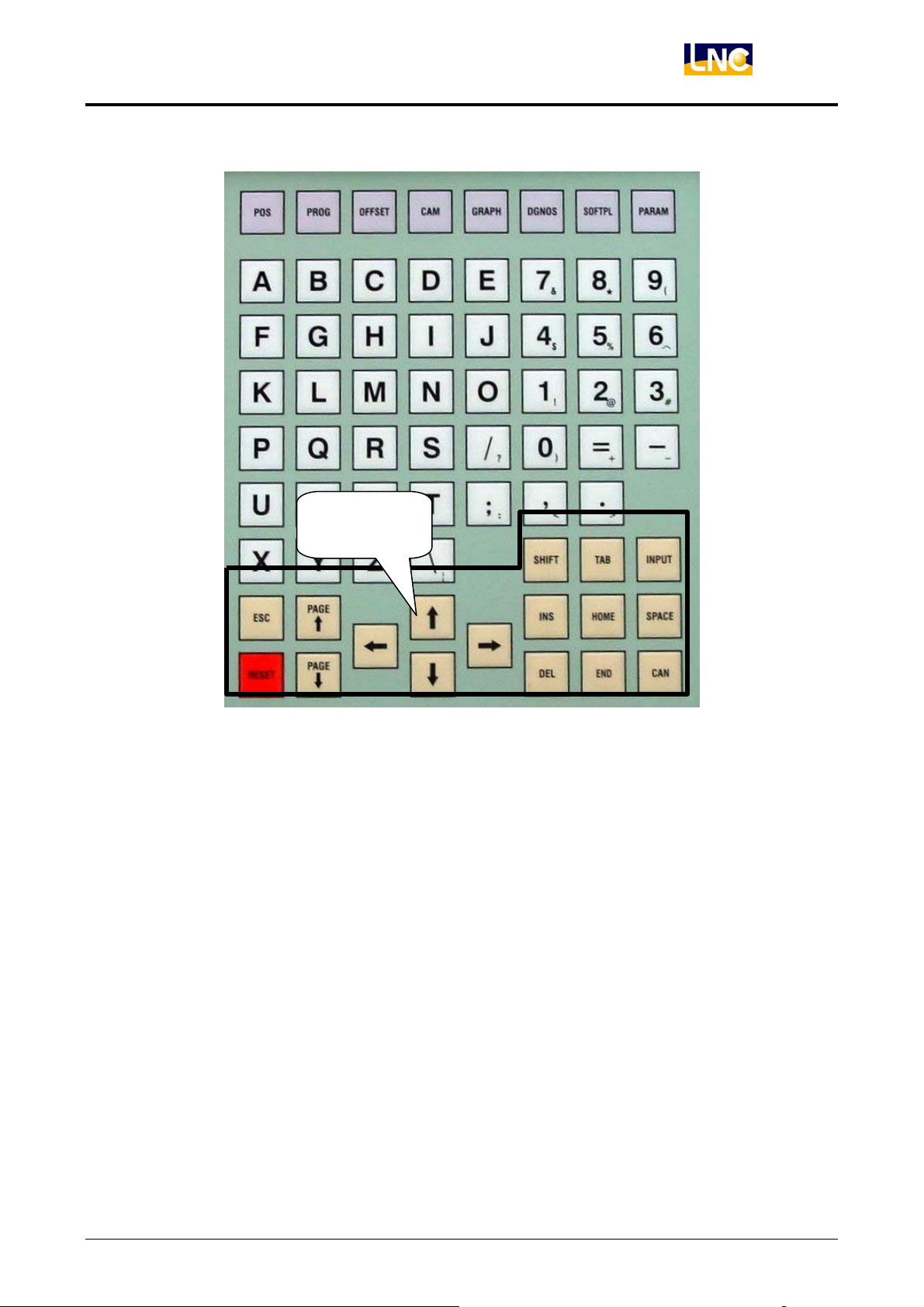
(5) Editing Keys:
Using these keys with cursor on the screen will be able to modify program, to set
data and to change page.
<SHIFT>:To key-in special symbols with use of symbol number keys.
<INPUT>:To confirm entered data.
<INS> :To switch enter/replace characters modes.
<DEL>:To delete.
<HOME>:To return cursor to the beginning of the sentence when editing program.
<END>:To return cursor to the end of the sentence when editing program.
<SPACE>:To key-in into empty space.
<CAN>:To cancel the previous character.
<PAGE↑>:To turn to the previous page.
<PAGE↓>:To turn to the next page.
<→>:To move cursor right.
<←>:To move cursor left.
<↑>:To move cursor up.
<↓>:To move cursor down.
<RESET>:To reset system.
8
LNC Technology Co., Ltd.
Page 14
LNC-M650
CNC Operation
Editing Keys
LNC Technology Co., Ltd. 9
Page 15
LNC-M650
CNC Operation
2.3 Screen and Function Description
8 function groups in this controller: POS, PROG, OFFSET, CAM, GRAPH, DGNOS,
SOFTPL and PARAM. Using 【….】 to indicate function keys at bottom and at right of the
screen and using <….> to indicate keys on MDI panel.
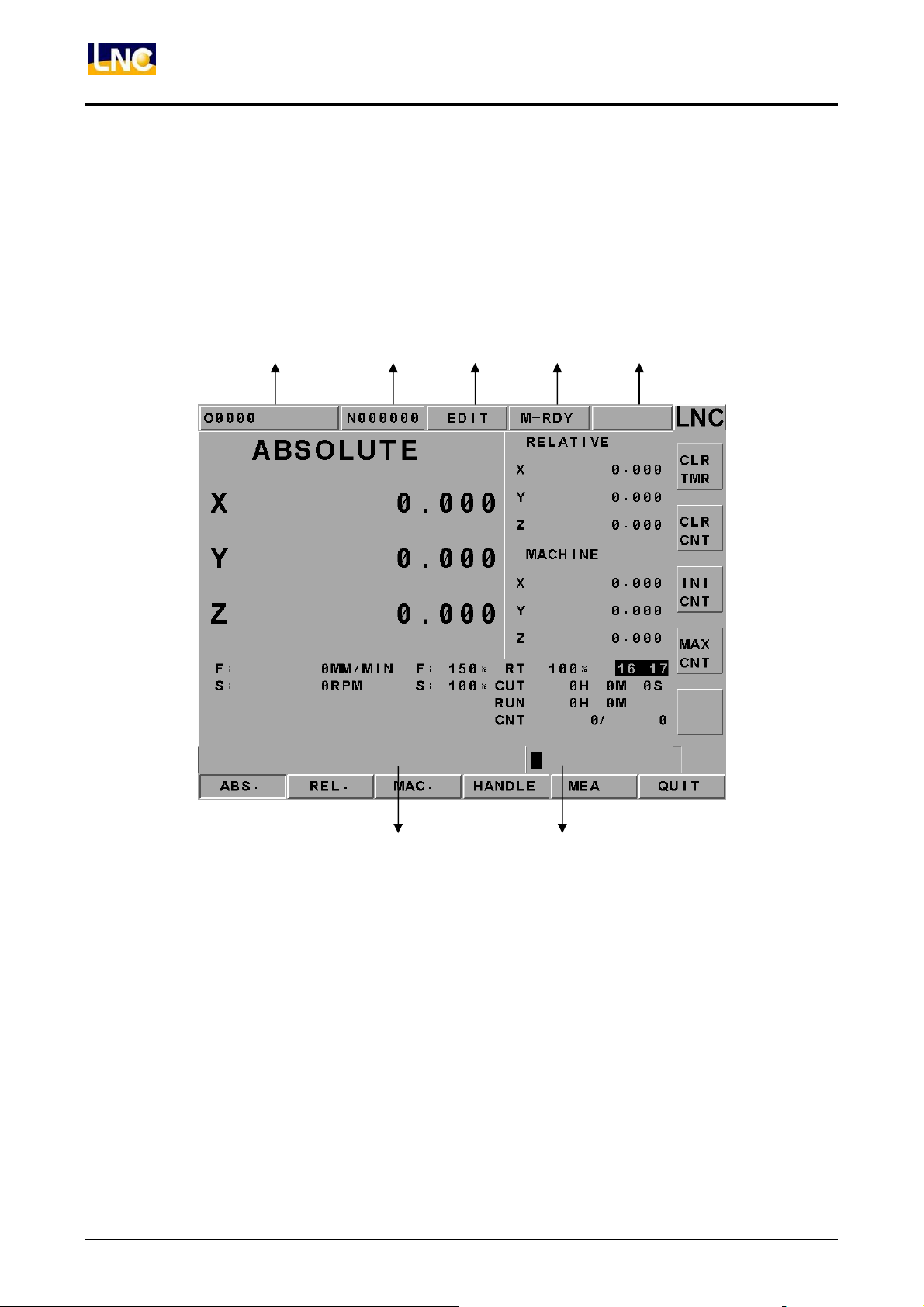
2.3.1 Display Screen Layout
1 2 3 4 5
1:present designate file name
2:present single block that is executed by controller
3:CNC mode signal
4:machine condition signal
5:wrong alarm/warning message
6:simply message hint area
7:entry area
7 6
10
LNC Technology Co., Ltd.
Page 16
LNC-M650
CNC Operation
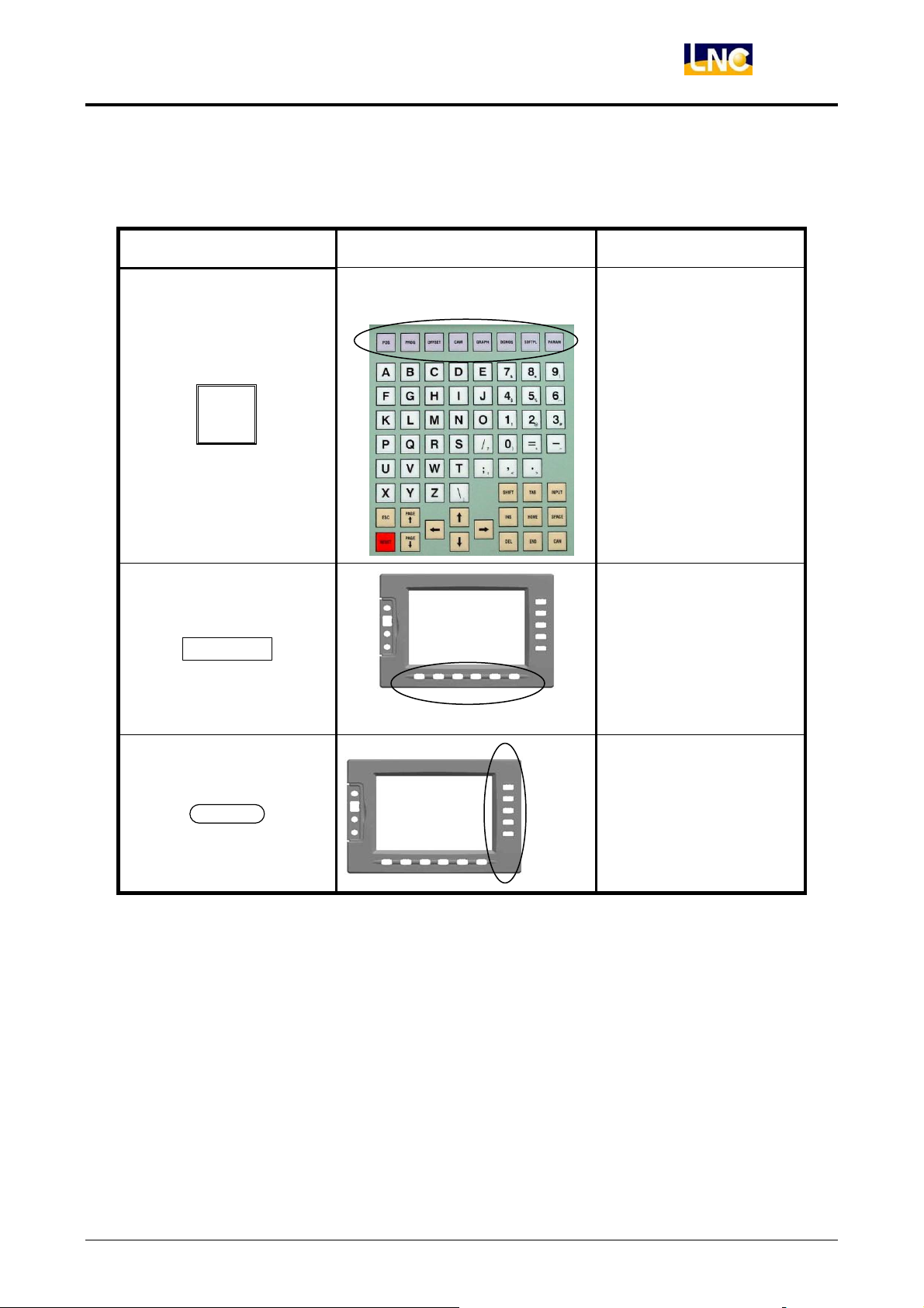
2.3.2 Function Group Figure
Figure Example Real Example Indication
Function Group
Function group keys
on MDI Panel.
Main function keys at
button of LCD.
Main
Sub
Sub function keys at
right of LCD.
LNC Technology Co., Ltd. 11
Page 17
LNC-M650
CNC Operation
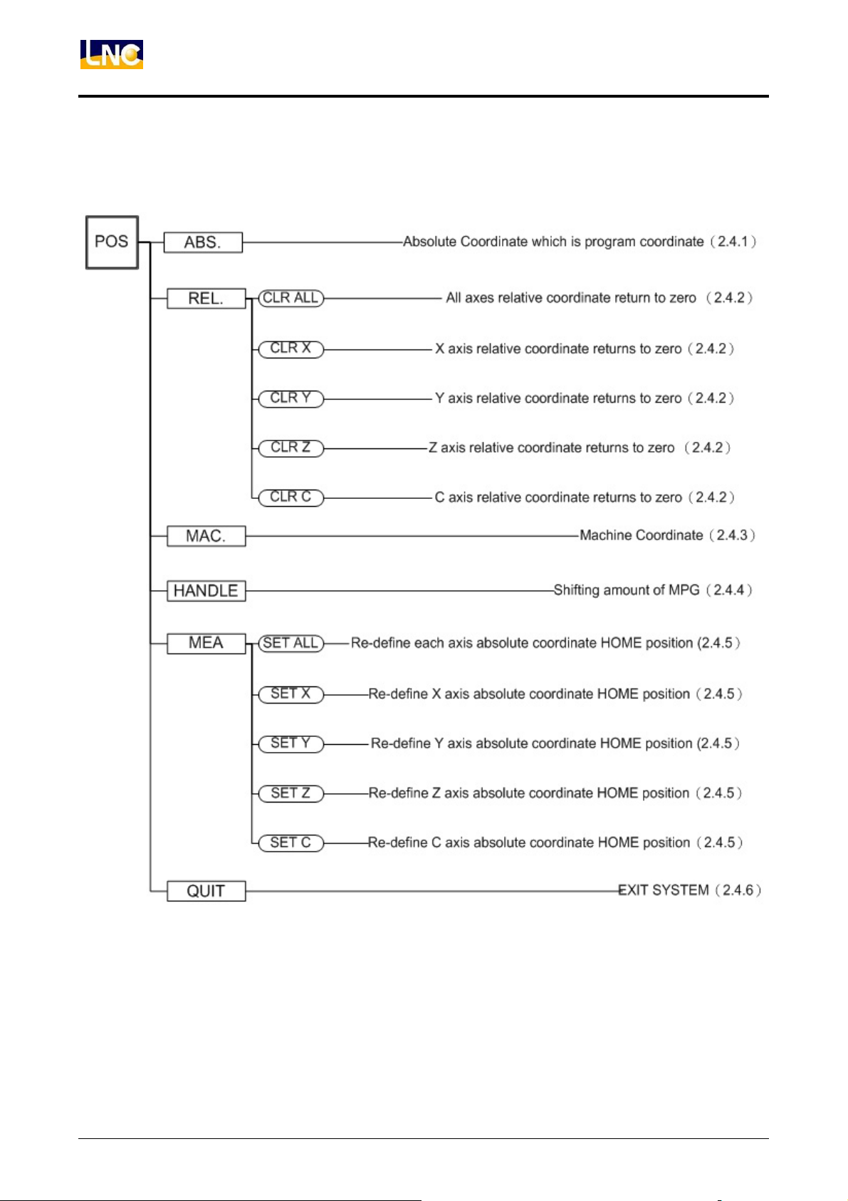
POS Function Key Tree Figure
12
LNC Technology Co., Ltd.
Page 18
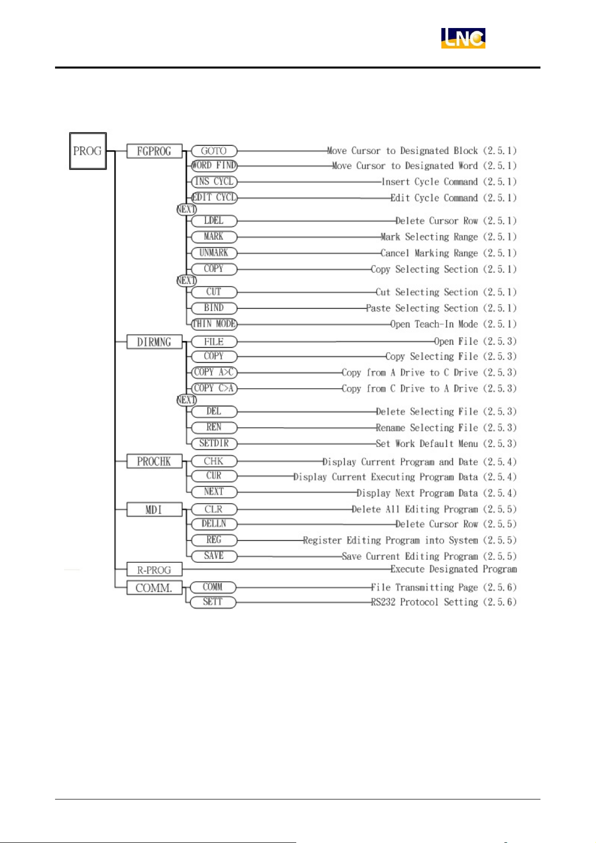
PROG Function Key Tree Figure
LNC-M650
CNC Operation
LNC Technology Co., Ltd. 13
Page 19
LNC-M650
CNC Operation
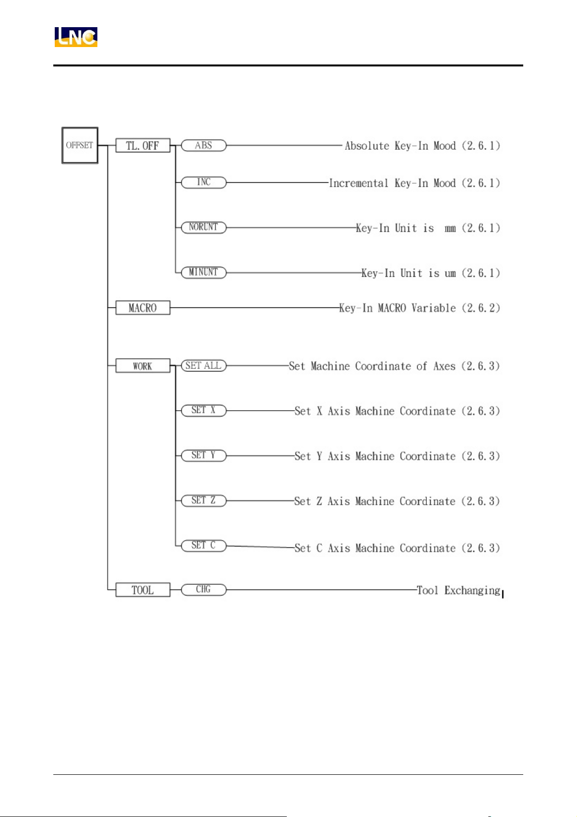
OFFSET Function Key Tree Figure
14
LNC Technology Co., Ltd.
Page 20
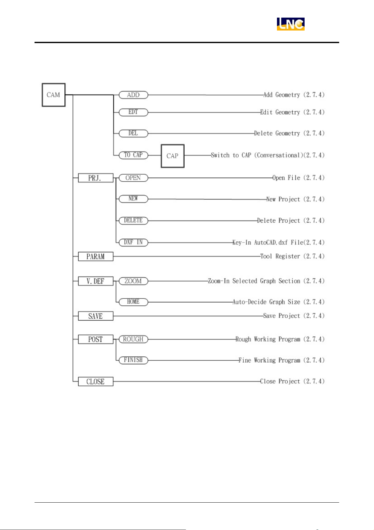
CAM Function Key Tree Figure
LNC-M650
CNC Operation
Note: There is no actual CAP key on MDI. Here just indicate easy use.
LNC Technology Co., Ltd. 15
Page 21
LNC-M650
CNC Operation
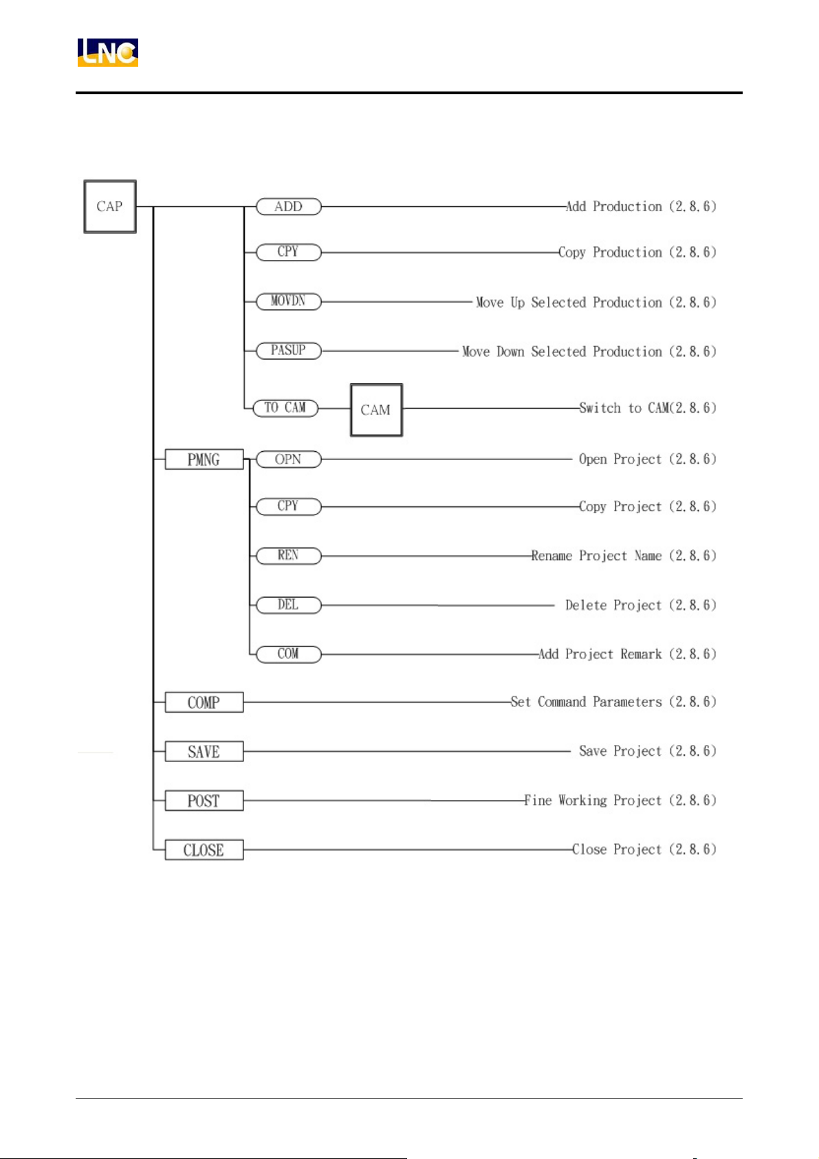
CAP Function Key Tree Figure
Note: There is no actual CAP key on MDI. Here just indicate easy use.
16
LNC Technology Co., Ltd.
Page 22

GRAPH Function Key Tree Figure
LNC-M650
CNC Operation
LNC Technology Co., Ltd. 17
Page 23
LNC-M650
CNC Operation
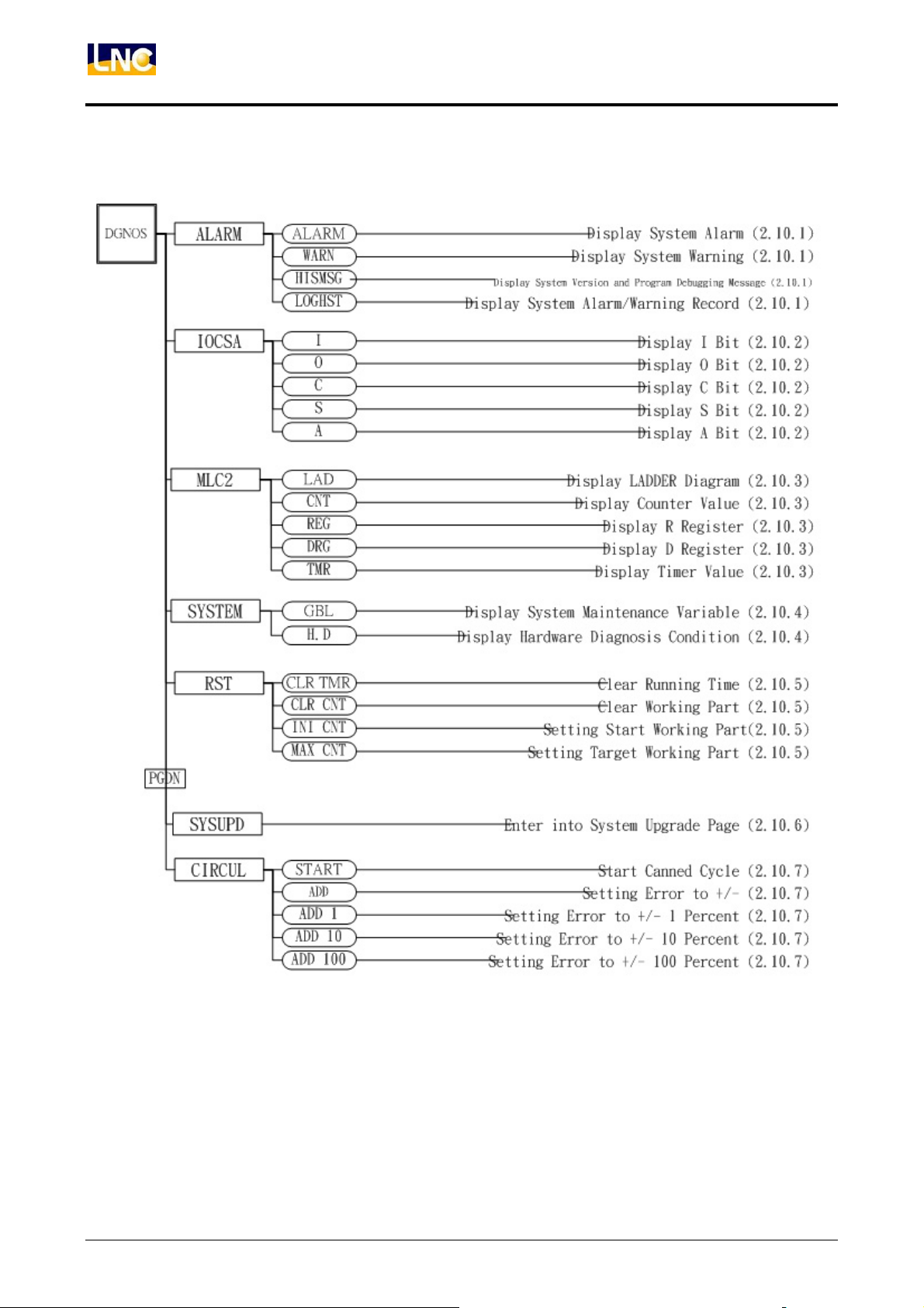
DGNOS Function Key Tree Figure
18
LNC Technology Co., Ltd.
Page 24
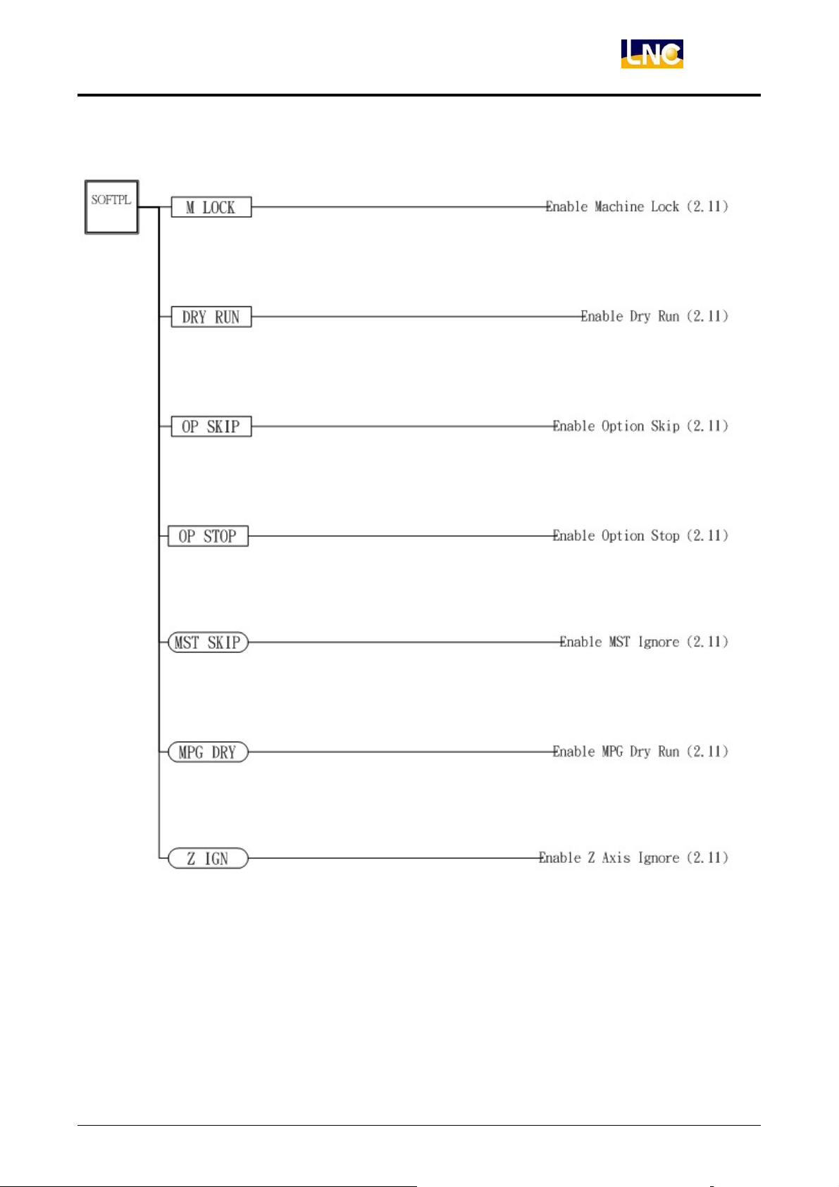
SOFTPL Function Key Tree Figure
LNC-M650
CNC Operation
LNC Technology Co., Ltd. 19
Page 25
LNC-M650
CNC Operation
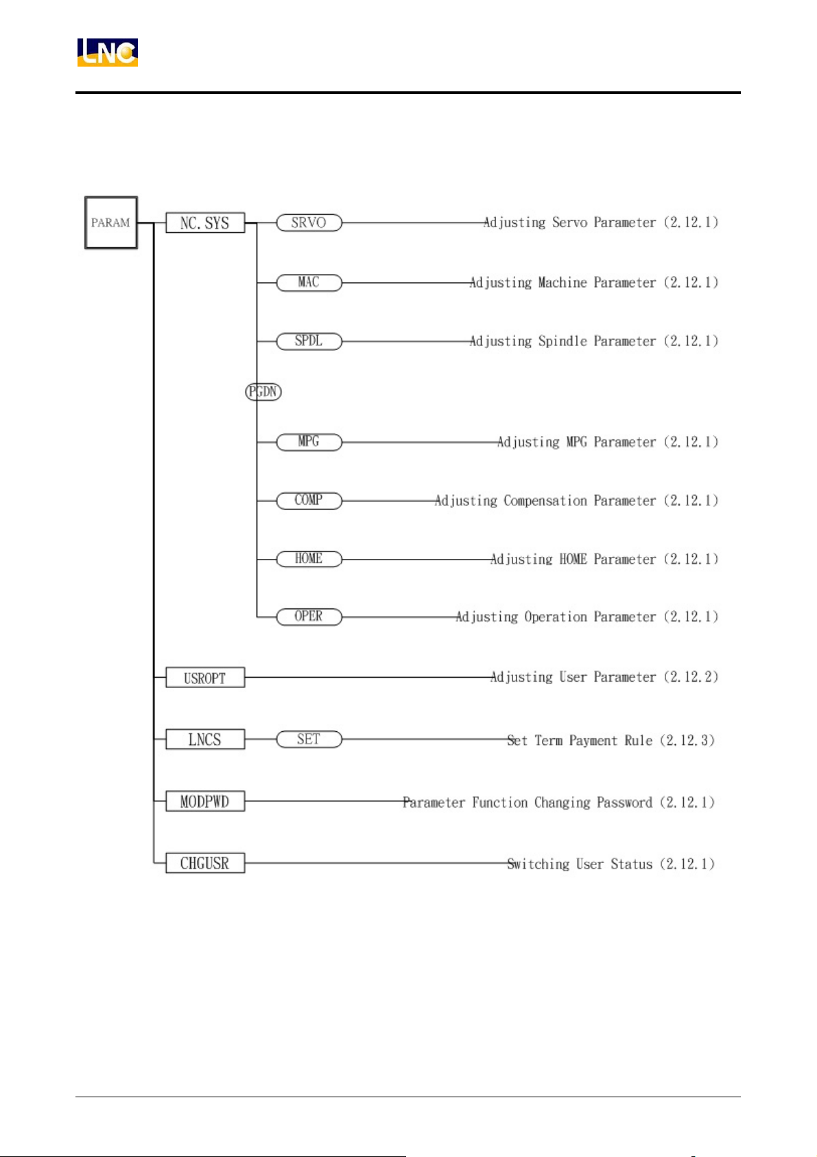
PARAM Function Key Tree Figure(Machine Maker)
20
LNC Technology Co., Ltd.
Page 26
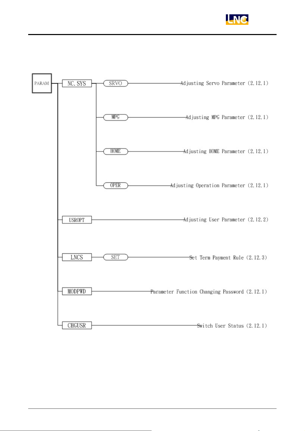
PARAM Function Key Tree Figure(End-User)
LNC-M650
CNC Operation
LNC Technology Co., Ltd. 21
Page 27
LNC-M650
CNC Operation
2.4 POS Function
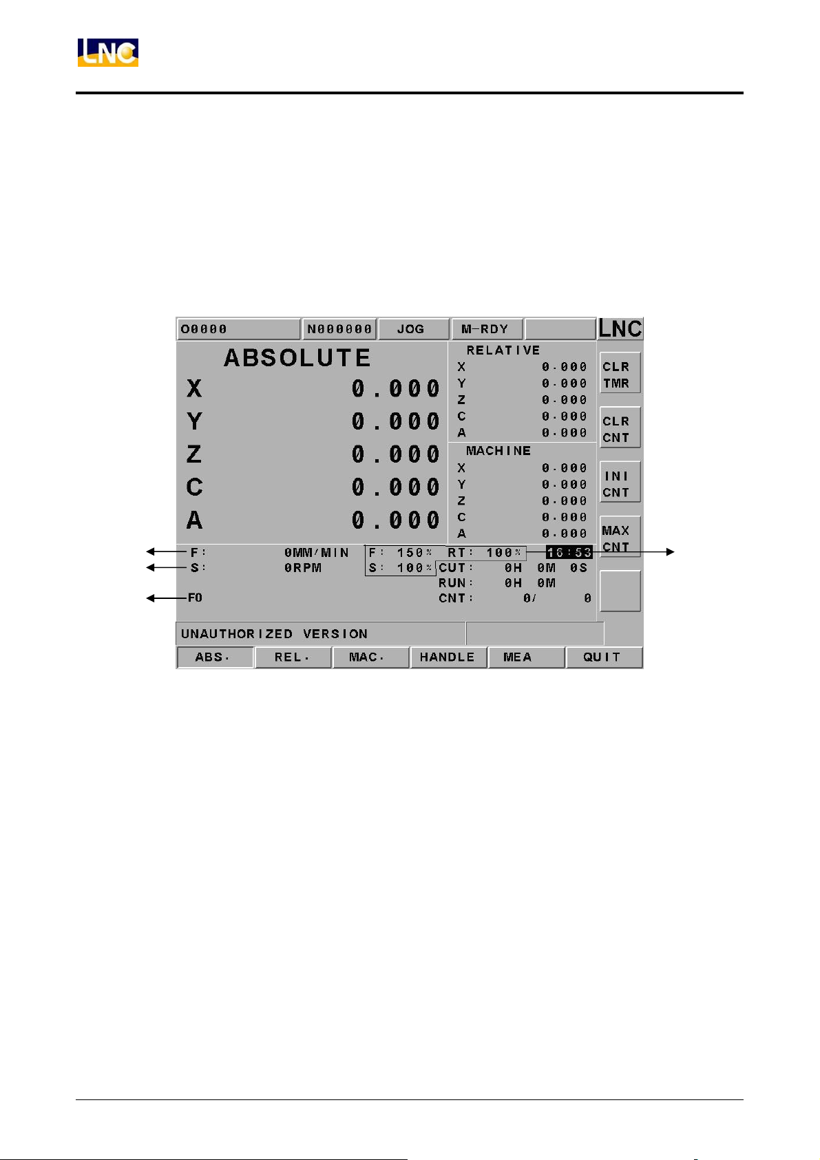
Pressing <POS> key to enter into the coordinate display screen. There are 6 main
function key selections for users. Users will be able to choose 6 screen displays by
pressing those function keys which are 【ABS.】, 【REL.】, 【MAC.】 , 【RST】
and 【QUIT】. There are some command information that will is displayed in those
screens, which will be described separately as following:
1
2
3
4
Figure 2.4-1 POS Function Display Screen
1. Actual Feed Rate:Feed rate of servo structure, the composite speed of 3 servo axes.
2. Spindle Rotational Speed:The actual spindle rotational speed at a certain time.
3. Message Hint Row:F0(Feedrate is 0), SBK(Single Block Executing), BDT(Optional
Single Block Jump), DRN(Program Dry Run), MLK(Machine Lock), OPS(Optional
Program Stop)and ABS(Absolute Encoder Reading).
4. Feedrate Condition:Feedrate percentage, rapidly percentage, rotational percentage.
22
LNC Technology Co., Ltd.
Page 28
LNC-M650
CNC Operation
2.4.1 ABSOLUTE COORDINATE
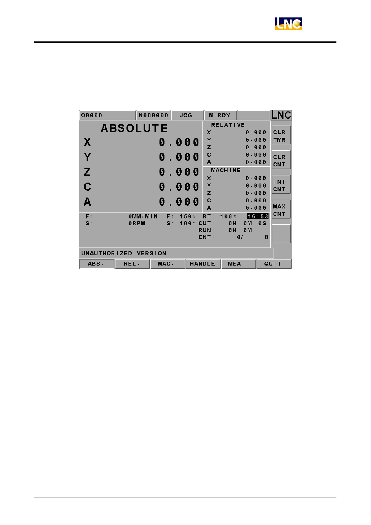
Pressing 【ABS.】 to enter into absolute coordinate screen. Beside the absolute coordinate
screen are sub-screens for【REL】, and【MAC】.
Figure 2.4-2 【ABS.】Screen
Absolute coordinate is the program coordinate, which is [present value – tool offset =
program value.] This will display the present executing position of each axis minus each
axis offset.
LNC Technology Co., Ltd. 23
Page 29
LNC-M650
CNC Operation
2.4.2 RELATIVE COORDINATE
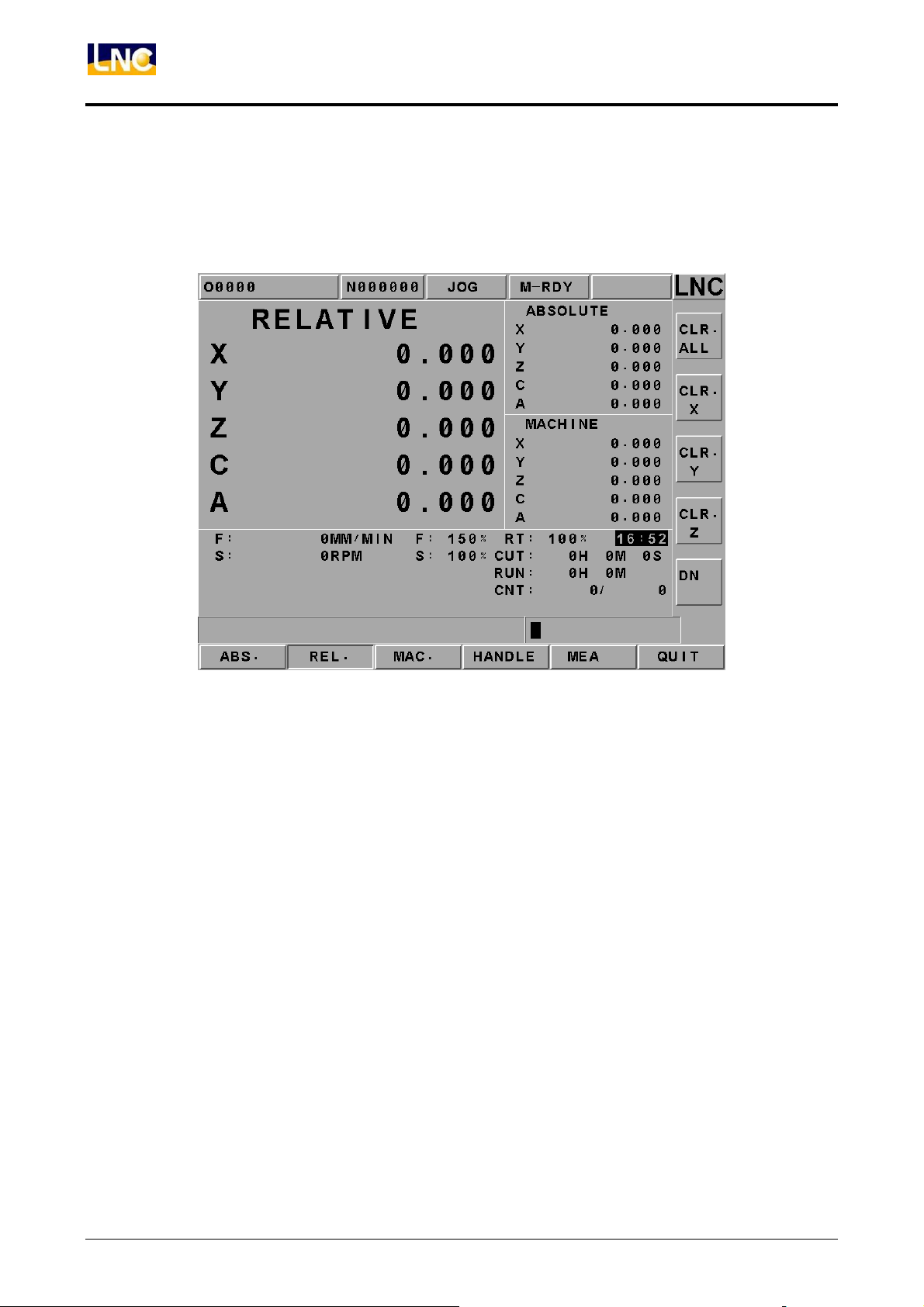
Pressing 【REL.】to enter into the relative coordinate screen. Beside the relative coordinate
screen are sub-screens for 【ABS.】 and 【MAC.】.
Figure 2.4-3 【REL.】Screen
The relative coordinate system means the distance between the present position and any
point that is decided by users. So users can set the relative coordinate value to zero
anytime, or enter the non-zero value directly.
If want to reset the coordinate value and to let X coordinate to 100.00, Y coordinate to
200.000 and Z coordinate to 300.000, only need to set X100, Y200, Z300. Then, pressing
<INPUT> to reset the coordinate value immediately.
If want to set the 3 axes relative coordinate values to zero separately or at the same time,
users only need to press the corresponding sub-function buttons 【CLR. X】, 【CLR. Y】,
【CLR. Z】, 【CLR. ALL】 to execute the corresponding clean.
24
LNC Technology Co., Ltd.
Page 30
LNC-M650
CNC Operation
2.4.3 MACHINERY COORDINATE
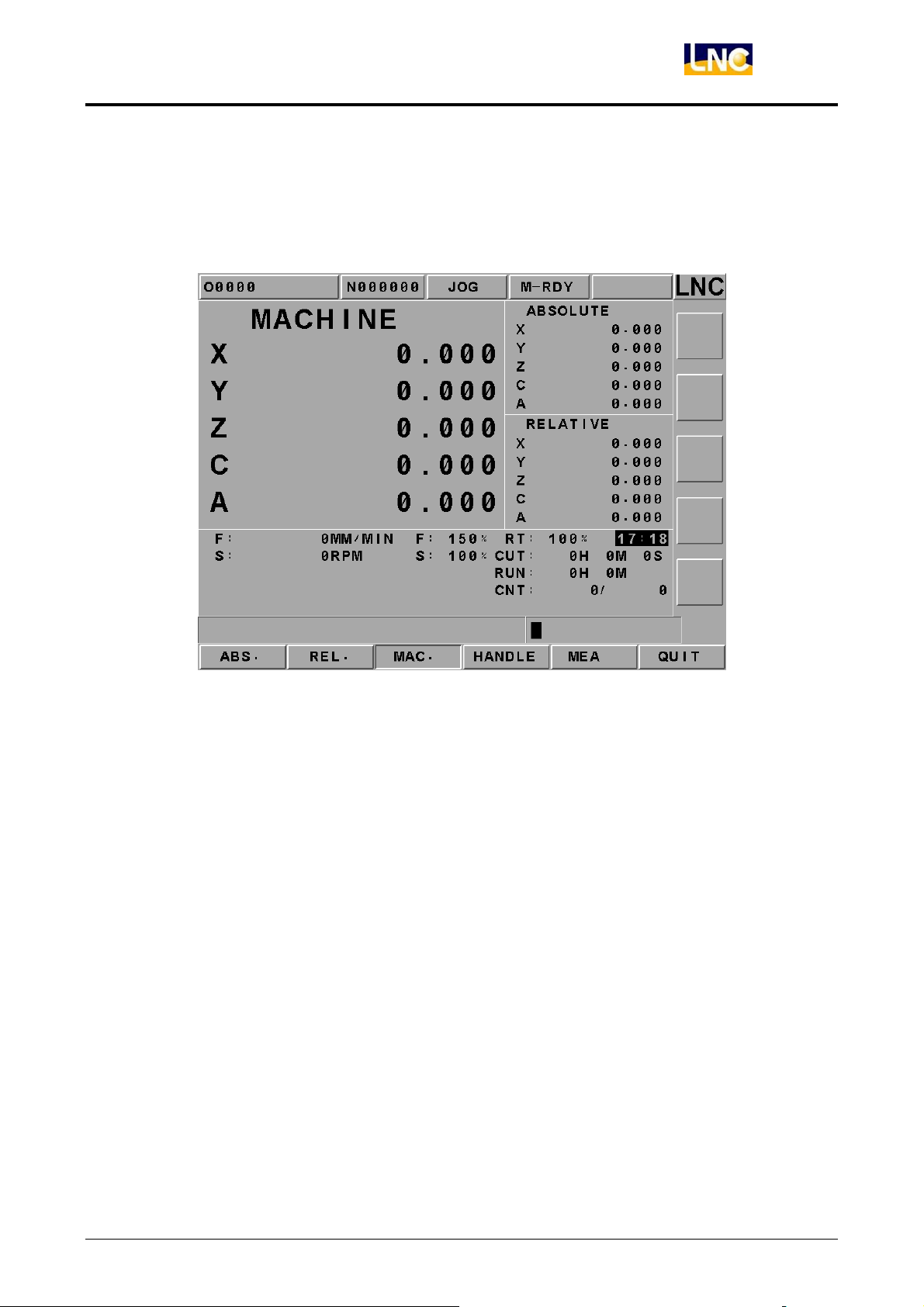
Pressing 【 MAC.】 to enter into the relative coordinate screen. Beside the machine
coordinate screen are sub-screens for 【ABS.】 and 【REL.】.
Figure 2.4-4 【MAC.】Screen
Machine coordinate is the distance of the present position corresponding to the reference
point. Each machine has its own reference point. For safety concern, please looking for
the reference point whenever reboot machine before executing work.
LNC Technology Co., Ltd. 25
Page 31
LNC-M650
CNC Operation
2.4.4 MEA (Measure)
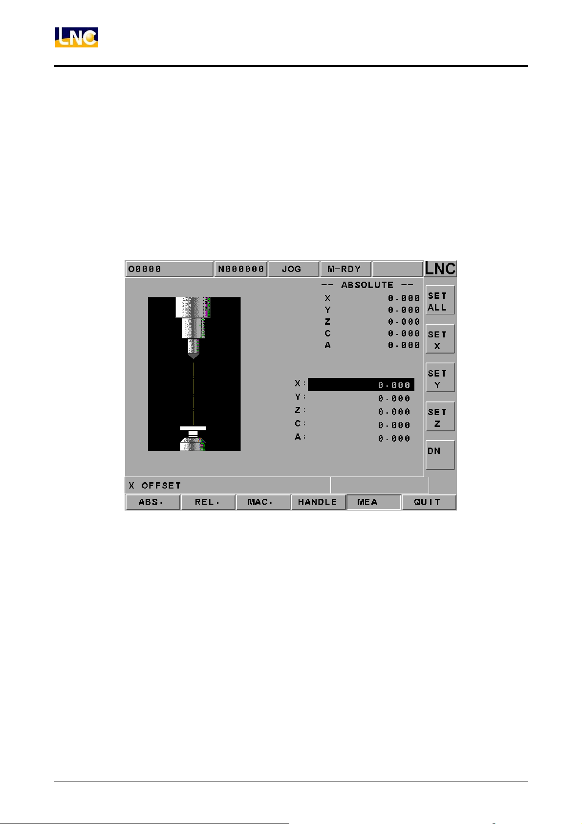
For program reference point setting, this controller provides setting methods for two types
of program coordinates. One of the methods is to enter the position of the machine
coordinate program definition at the [WORK]. The second method is using G92 to define.
This function page [MEA] is using the latter method, which is using the tool position to set
the reference point of the new coordinate system. The original coordinate system will be
the working coordinate system. Once set, the absolute value is refer to this coordinate
system to calculate. This system provides the setting method like the above Figure.
Figure 2.4-5 MEA Screen
【ALL SET】
【 SET X】
【 SET Y】
【 SET Z】
Using G92 to redefine X, Y, and Z axes absolute reference point position.
Using G92 to set X axis absolute coordinate value to 0.
Using G92 to set Y axis absolute coordinate value to 0.
Using G92 to set Z axis absolute coordinate value to 0.
Example:
1. Moving tool to touch working part’s surface.
2. Pressing 【SET Z】, using G92 to set Z axis coordinate to 0. Re-define Z axis reference
point of absolute coordinate.
Note: Must complete home return procedure before operating no matter using which
method to reset coordinate system.
26
LNC Technology Co., Ltd.
Page 32
LNC-M650
CNC Operation
2.4.5 EXIT
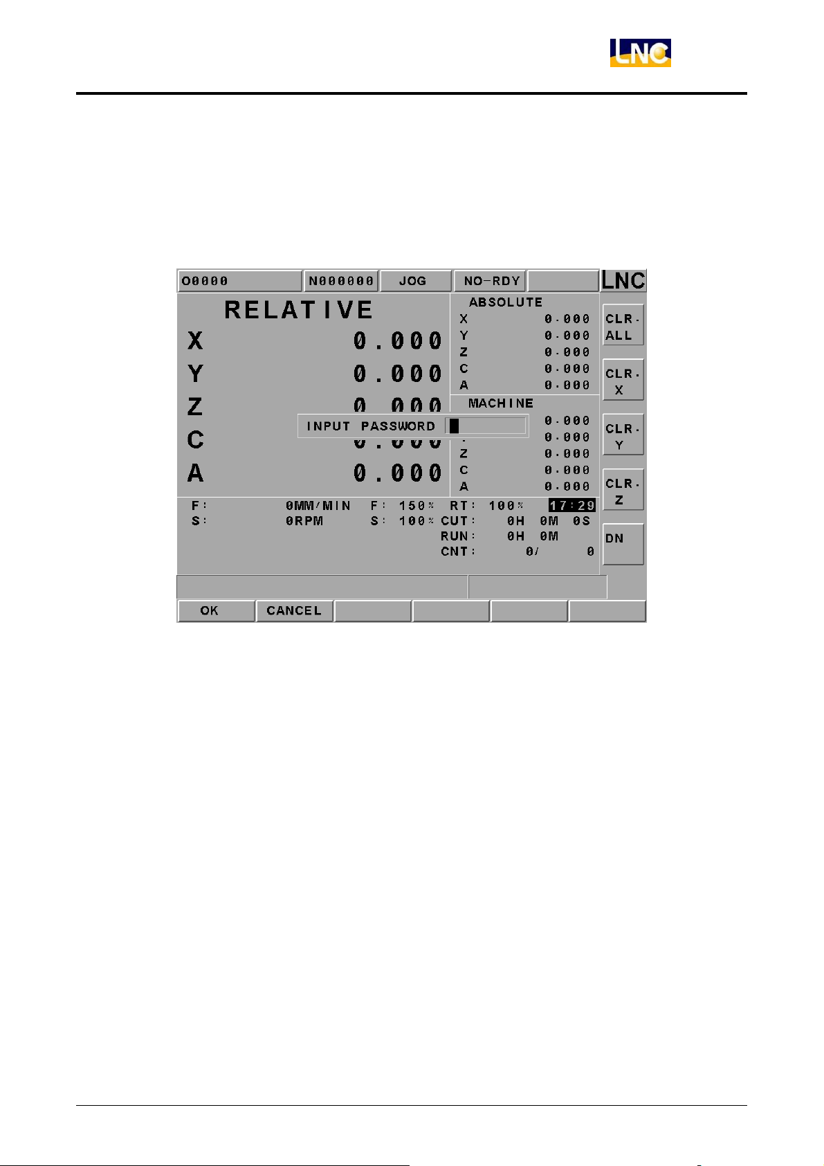
Pressing 【EXIT】function button to enter into code entry windows and key-in correct codes.
Pressing【OK】key to exit CNC system and returning back to DOS system. Pressing
【CANCEL】key to return back to program and to continue executing.
Figure 2.4-6 EXIT
LNC Technology Co., Ltd. 27
Page 33
LNC-M650
CNC Operation
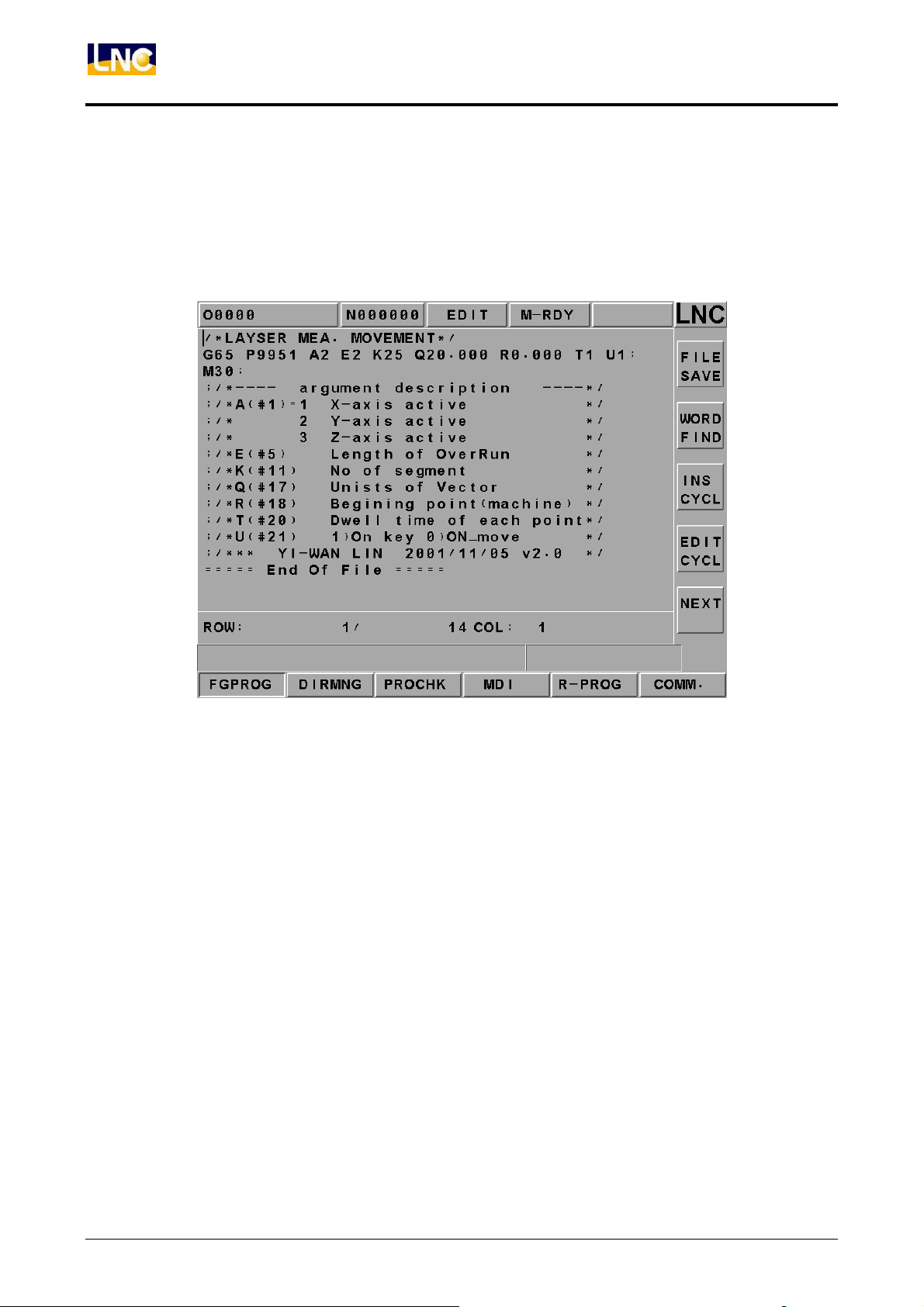
2.5 PROG
Pressing <PROG> to enter into program function group screen. This function group
provides part program editing, checking, file managing, RS232 transmitting and other
related functions.
Figure 2.5-1 PROG Screen
28
LNC Technology Co., Ltd.
Page 34
LNC-M650
CNC Operation
2.5.1 FGPROG
Under editing condition, pressing【FGPROG】 to display the program content of the current
opened controller. At this time, using the sub-function button at the right side and the
entering rows at the bottom of the screen to do the program editing.
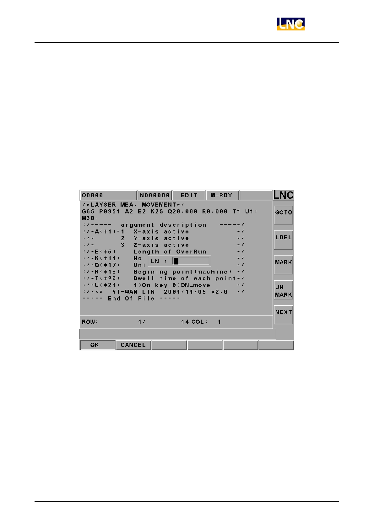
【GO TO】(Row Orientation)
Pressing【GO TO】function button at the right side to key-in “ROW’ number of the program
in the dialog box. Pressing【INPUT】 to move the cursor to the assigned row orientation.
Please refer to the below figure.
Figure 2.5-2 Row Orientation Page
Note: Not able to executing program enabling under editing mode.
LNC Technology Co., Ltd. 29
Page 35
LNC-M650
CNC Operation
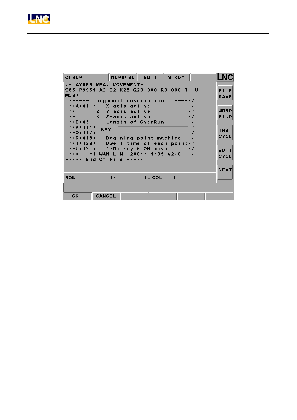
【WORD FIND】
Able to searching a specific block of characters.
Figure 2.5-3 Searching Function Page
30
LNC Technology Co., Ltd.
Page 36
LNC-M650
CNC Operation
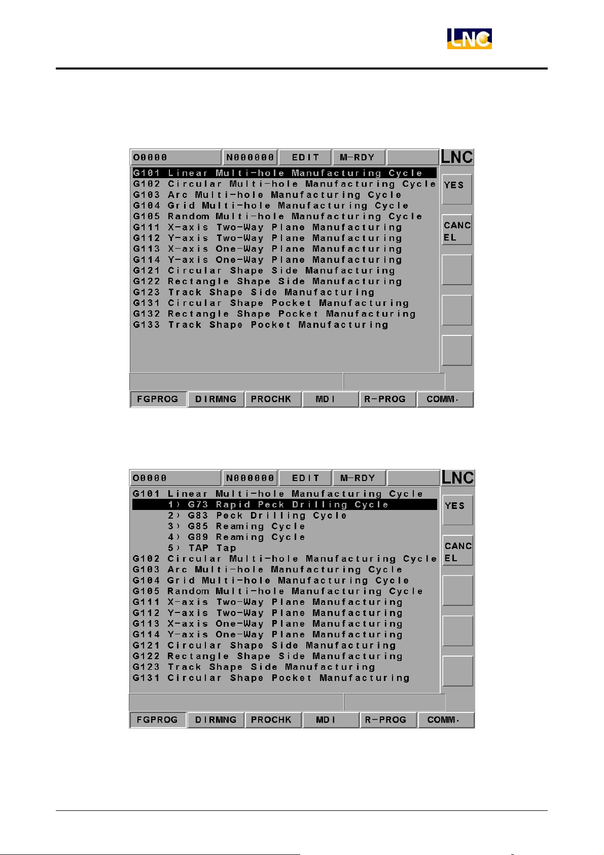
【INS CYCL】
This function is to provide each working method in order to product program rapidly.
Figure 2.5-4 Insert Page-1
Pressing “Input” after selecting working method.
Figure 2.5-5 Insert Page-2
LNC Technology Co., Ltd. 31
Page 37
LNC-M650
CNC Operation
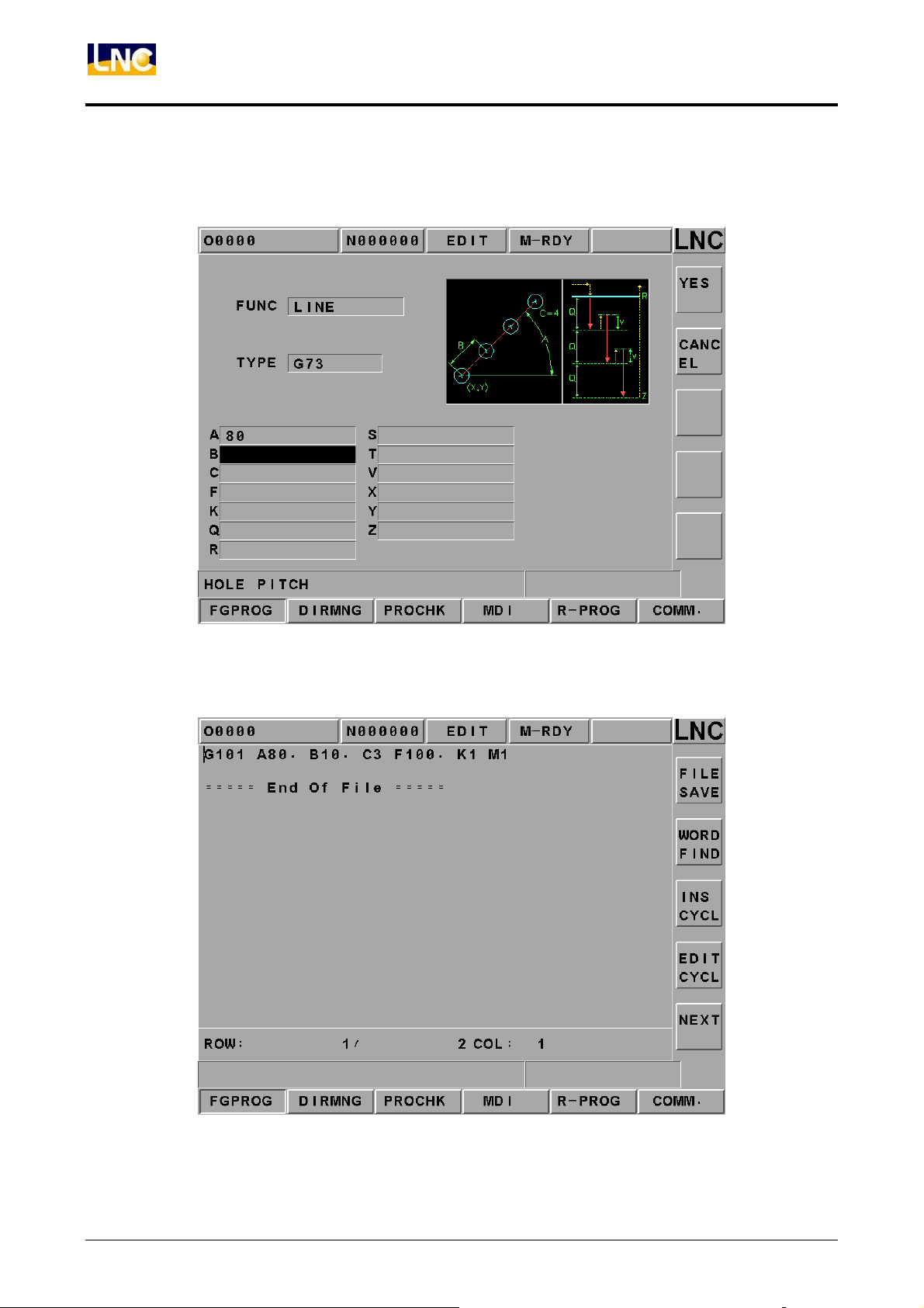
To press “Input” key to enter into the following Figure page. To move the highlighter to
each parameter column and then press <INPUT> key.
Figure 2.5-6 Insert Page-3
Program code page is as following after pressing 【OK】.
32
Figure 2.5-7 Program Code Page
LNC Technology Co., Ltd.
Page 38
LNC-M650
CNC Operation
【EDIT CYCL】
This function key is effective when the editing cursor is stop at 【INS CYCL】 command
block or there is G Code in that 【INS CYCL】 block. To press this key will enter into
“Insert-3” page. If there is no assigned M Parameter (working style) value after G code,
“Insert-2” page will occur.
【LDEL】(Row Delete)
Able to delete a row of program codes at the cursor position.
【MARK】
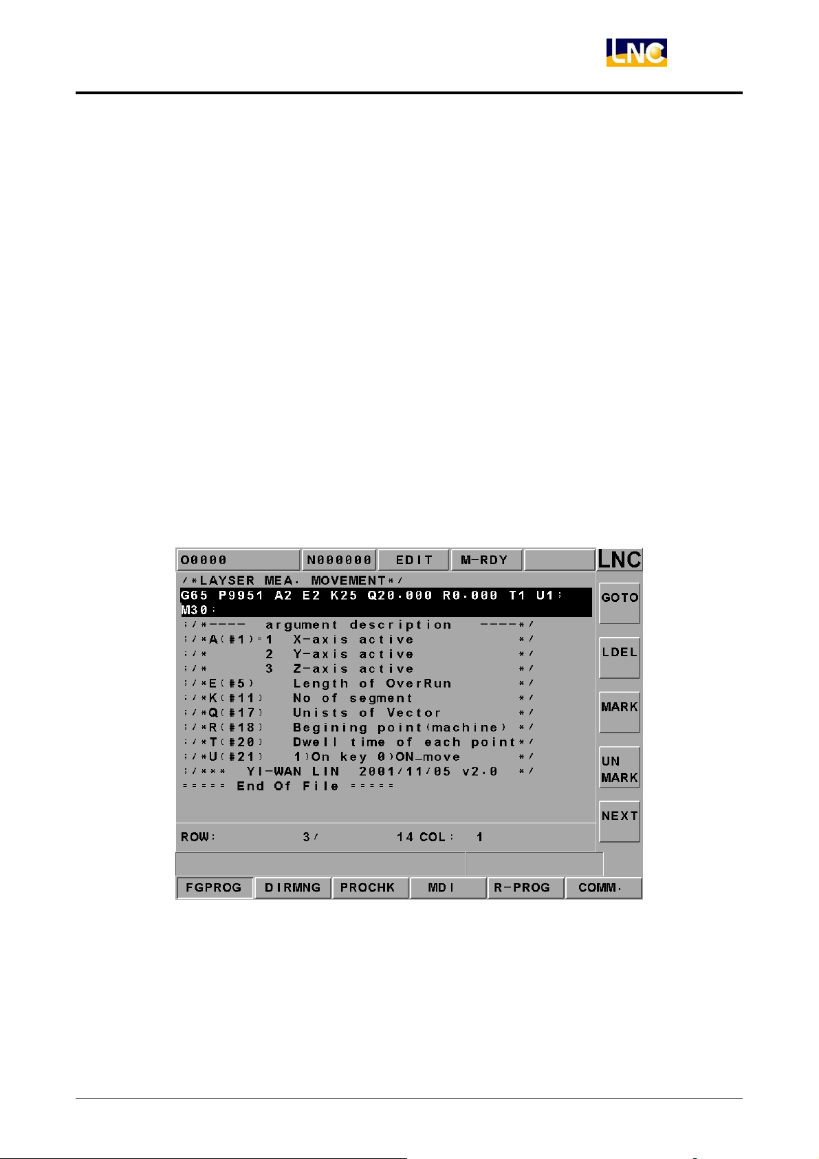
Pressing【MARK】at the right side of the screen to move the cursor to the wanted marking
row’s starting/ending point. Moving the cursor to the starting/ending position of the wanted
marking row and pressing the【MARK】function key again to mark the designated marking
rows. Please refer to the below figure.
Figure 2.5-8 Marking Function Page
LNC Technology Co., Ltd. 33
Page 39
LNC-M650
CNC Operation
【UNMARK】
To cancel previous marking sign.
【COPY】
To copy the marked program in local range.
【CUT】
To cut down the marked program in local range.
【BIND】
To paste on the program codes that are copied or cut at previous time.
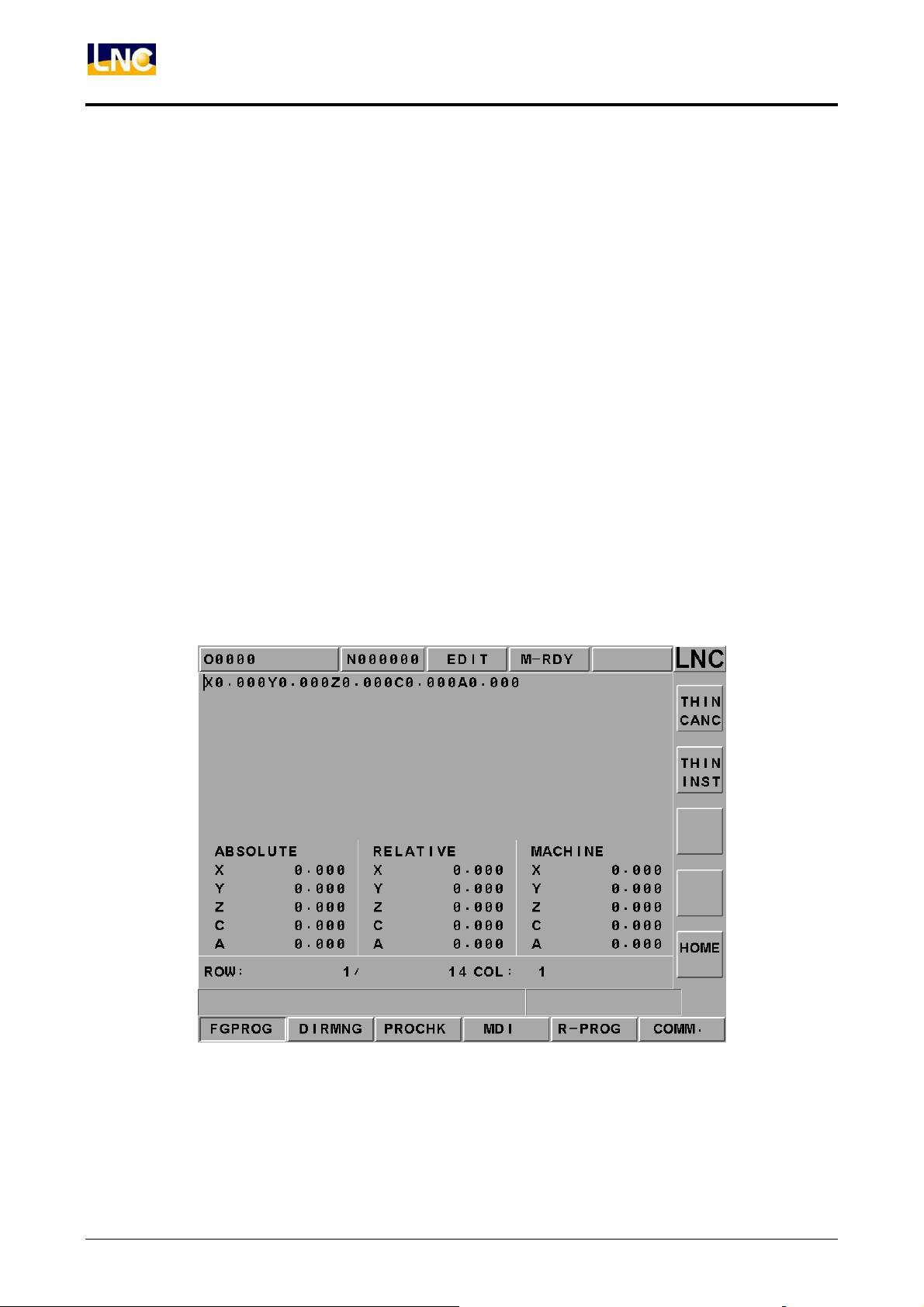
【THIN MODE】/【THIN CANC】
Absolute coordinate, relative coordinate, and machine coordinate will be popup after
pressing this key. Also, 【THIN INST】 will be popup at the right-hand side in order to
provide user to current absolute coordinate.
34
Figure 2.5-9 Teach-In Function Page
LNC Technology Co., Ltd.
Page 40
CNC Operation
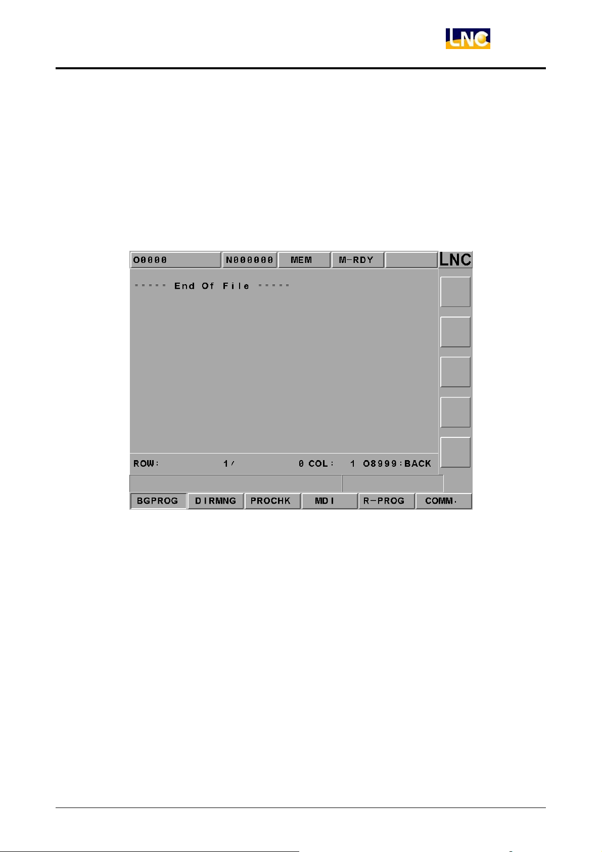
2.5.2 BGPROG (Background Program)
Pressing【BGPROG】to enter into background editing mode under auto mode.
Background editing allows users to edit another part program while executing one
part program in auto mode. Editing method and the environment of doing present
program in editing mode are totally the same.
Note: Background file is 08999 permanently.
LNC-M650
Figure 2.5-10 Background Editing Mode
LNC Technology Co., Ltd. 35
Page 41
LNC-M650
CNC Operation
2.5.3 DIRMNG (File Management)
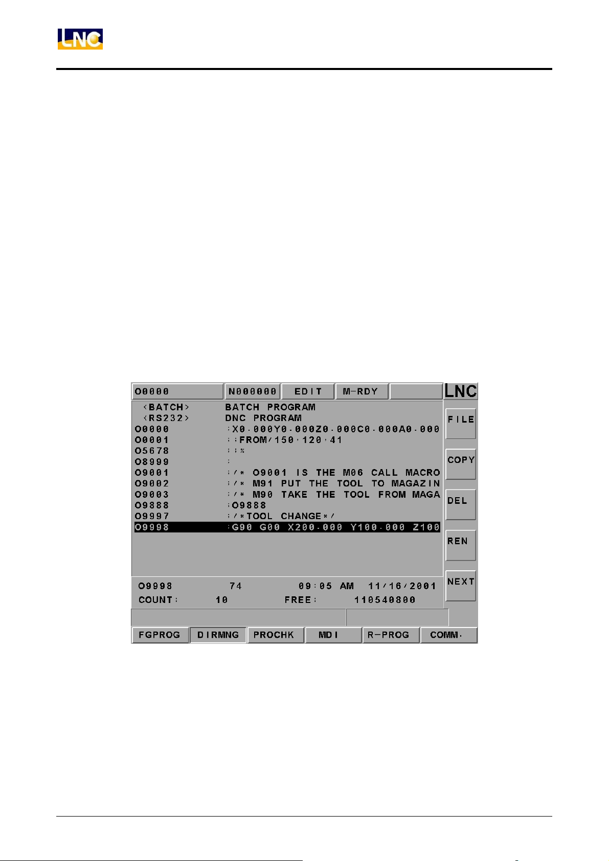
In file management screen, system provides the related file opening, copying, deleting,
renaming, and setting menu functions. A detailed description is as following.
【FILE】
1. Able to use direction key to choose the wanted open file after entering into the file
management screen. Also, users are able to open a file after pressing <INPUT>.
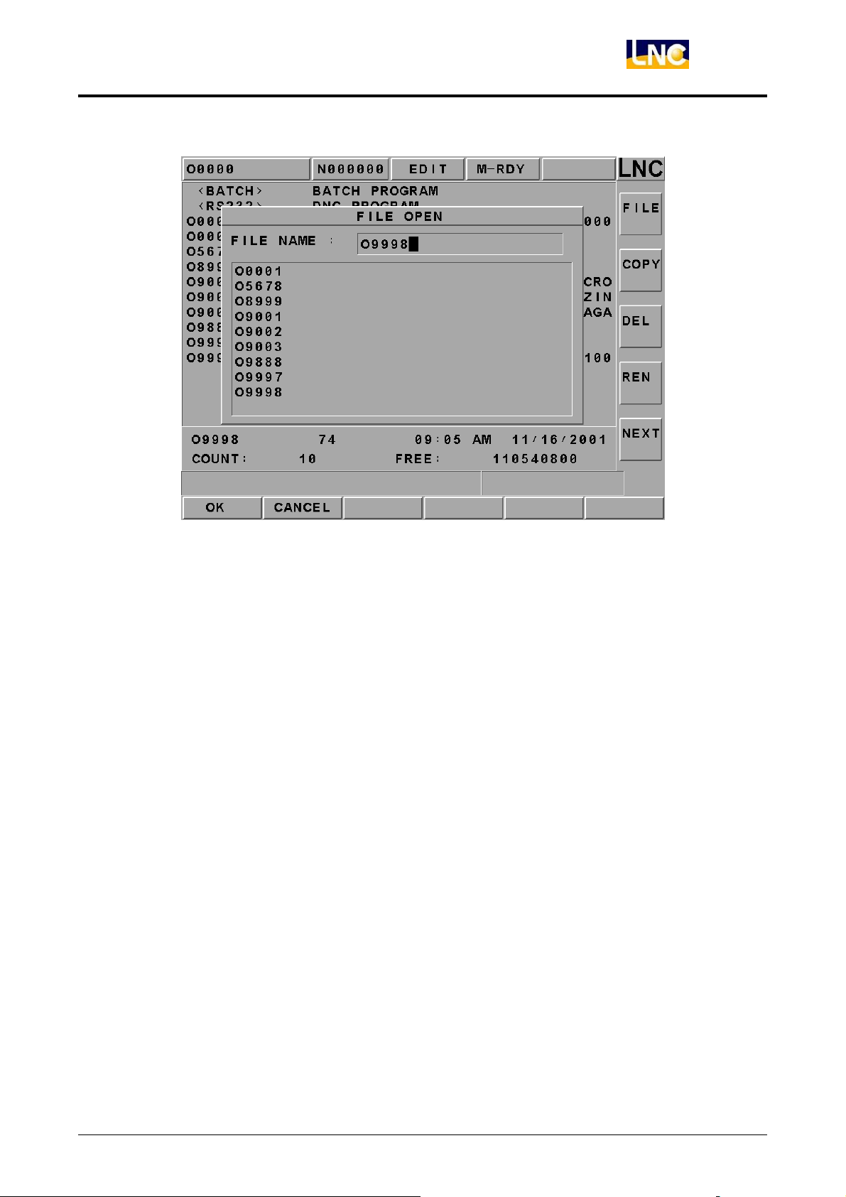
2. After pressing open file selection button, a dialog box will occur on the screen. Please
choose or key-in the wanted open file name and then pressing <INPUT> to open the
file.
3. The opened file is a background program under auto mode. Automatically setting the
opened file to the present program under editing mode means NOT able to open the
file under other modes.
36
Figure 2.5-11 DIRMNG Screen
LNC Technology Co., Ltd.
Page 42
LNC-M650
CNC Operation
Figure 2.5-12 Screen of Pressing【FILE】Button
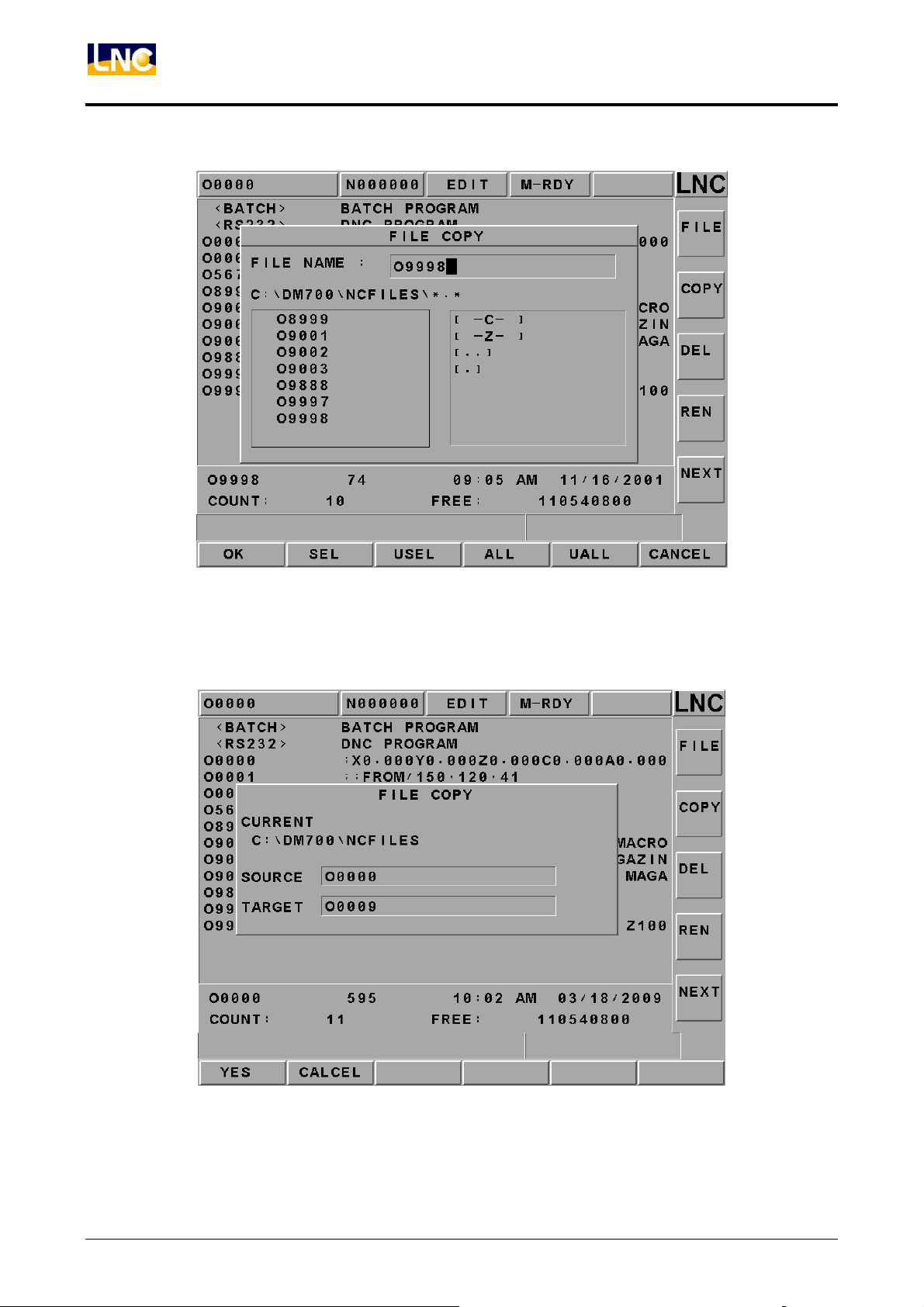
【COPY】
A dialog box of file copying will occur on the screen by pressing copy button. Users
are able to choose or enter the file’s path or file name as the source file when copy
files.
LNC Technology Co., Ltd. 37
Page 43
LNC-M650
CNC Operation
Figure 2.5-13 Screen of Pressing【COPY】Function Button
Able to enter the copied destination file name in the destination file column. If only enter
file name, then the file path is the system default value.
38
Figure 2.5-14 Screen of Key-In Destination File Name
LNC Technology Co., Ltd.
Page 44
LNC-M650
CNC Operation
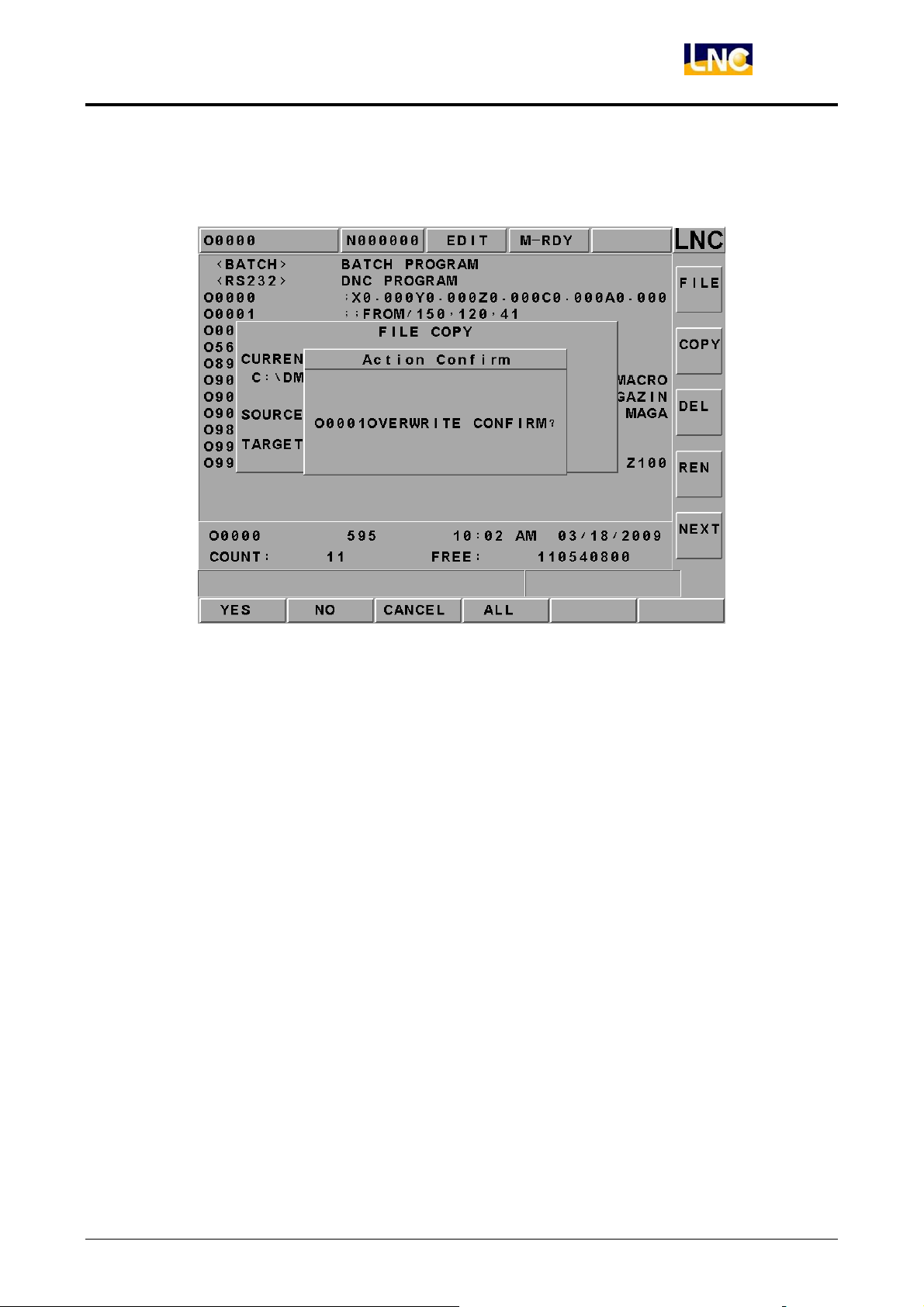
If the file is already existed, then the reminding windows will occur. Please confirm if want
to execute overwriting action.
Figure 2.5-15 Screen When the Copied File is Already Existed
If the program is copying, the message-reminding dialog box will occur “Copying….”.
When complete, the message-reminding dialog box will occur “Copy Complete”.
【COPY A>C】
To copy from floppy drive (A drive) to CF card (C drive) function. Operation is like【Copy】.
【Copy C>A】
To copy from CF card (C drive) to floppy drive (A drive) function. Operation is like【Copy】.
【DEL】
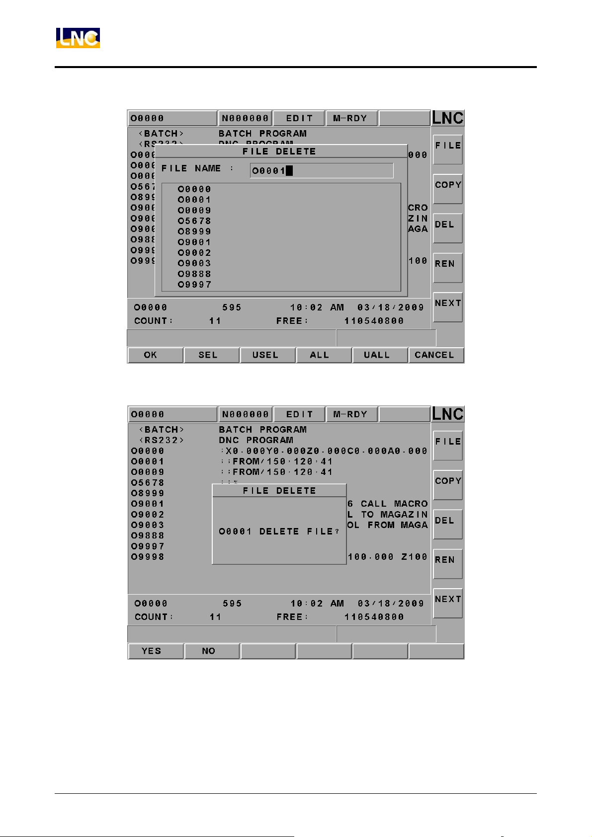
Pressing on this sub-function button, a file delete dialog box will appear on the screen.
Please choose the wanted delete file in that dialog box. After complete deleting, users can
use Program Table to confirm.
LNC Technology Co., Ltd. 39
Page 45
LNC-M650
CNC Operation
Figure 2.5-16 【DEL】Screen
40
Figure 2.5-17 Double Confirm Deleting Page
LNC Technology Co., Ltd.
Page 46
LNC-M650
CNC Operation
【REN】
1. After pressing rename function button, a rename file source windows will occur on the
screen. Users are able to choose the wanted change’s file name. Pressing confirm
button to enter into the file rename windows.
2. To enter the destination file name in the rename windows and then to press confirm
button. After rename complete, users will be able to use program list to confirm.
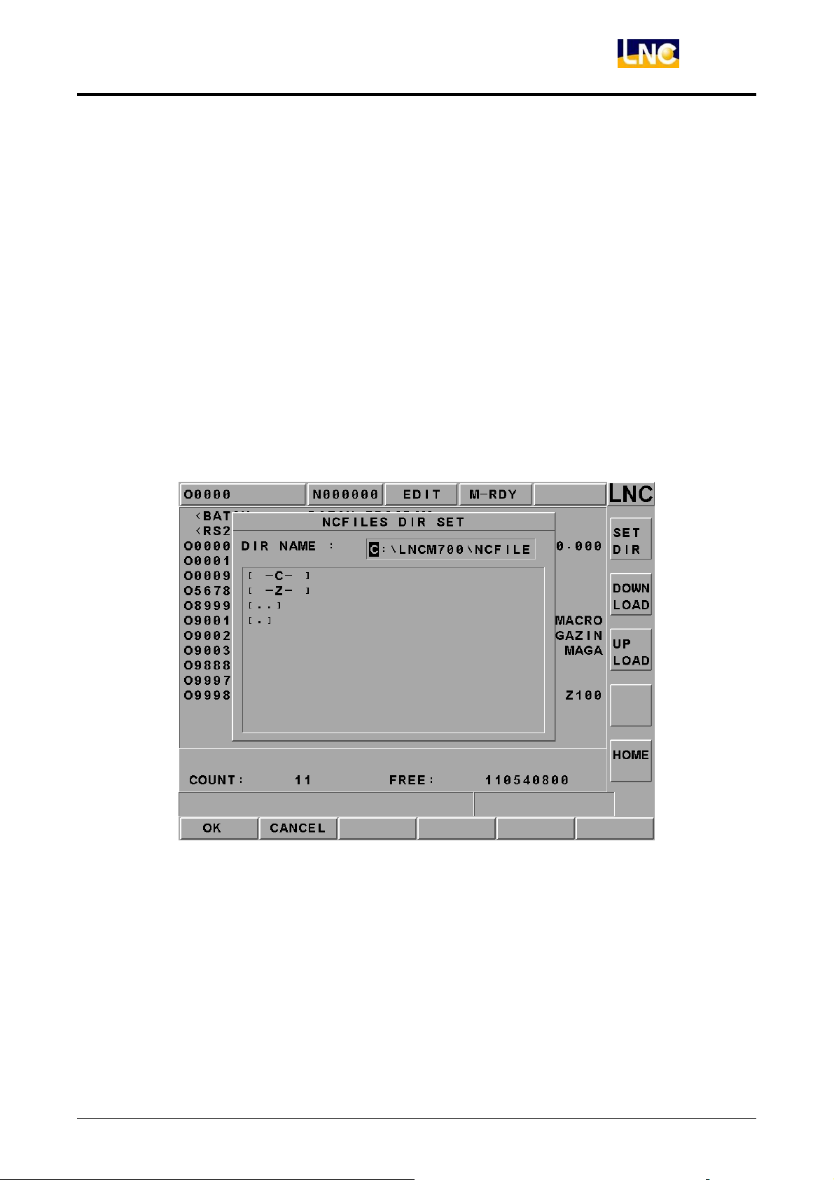
【DIR SET】
A dialog box of part program menu setting will occur on the screen by pressing this
sub-function button. Users are able to set the part program menu by using this dialog box
or by entering work path directly.
Figure 2.5-18 Screen when Setting Part Program Menu
LNC Technology Co., Ltd. 41
Page 47
LNC-M650
CNC Operation
2.5.4 PROCHK (Program Checking)
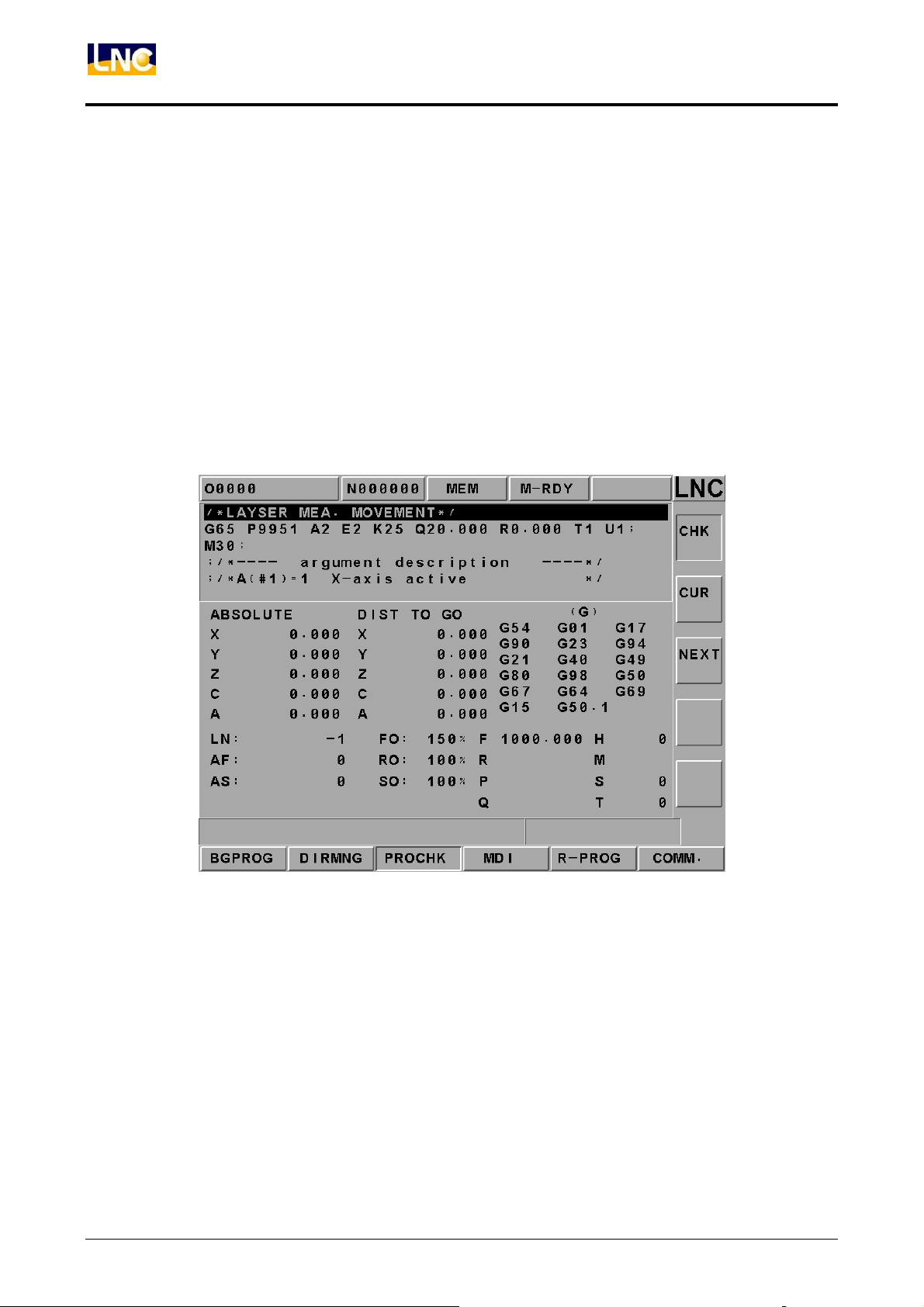
Under auto mode, pressing【PROCHK】function buttons to enter into the automatic
program checking screen as below figure. Sub-function buttons, at right side of the screen,
provide checking options.
【 CUR】
To display data information of the present executing single block.
【 NEXT】
【 CHK】
To display data information of the next single block
The upper half of the main screen will display program content and the
present executing program will be highlighted. The bottom half has
coordinate values, M/S/G/T codes present value, actual speed display
and etc.
42
Figure 2.5-19 【PROCHK】Screen
LNC Technology Co., Ltd.
Page 48
LNC-M650
CNC Operation
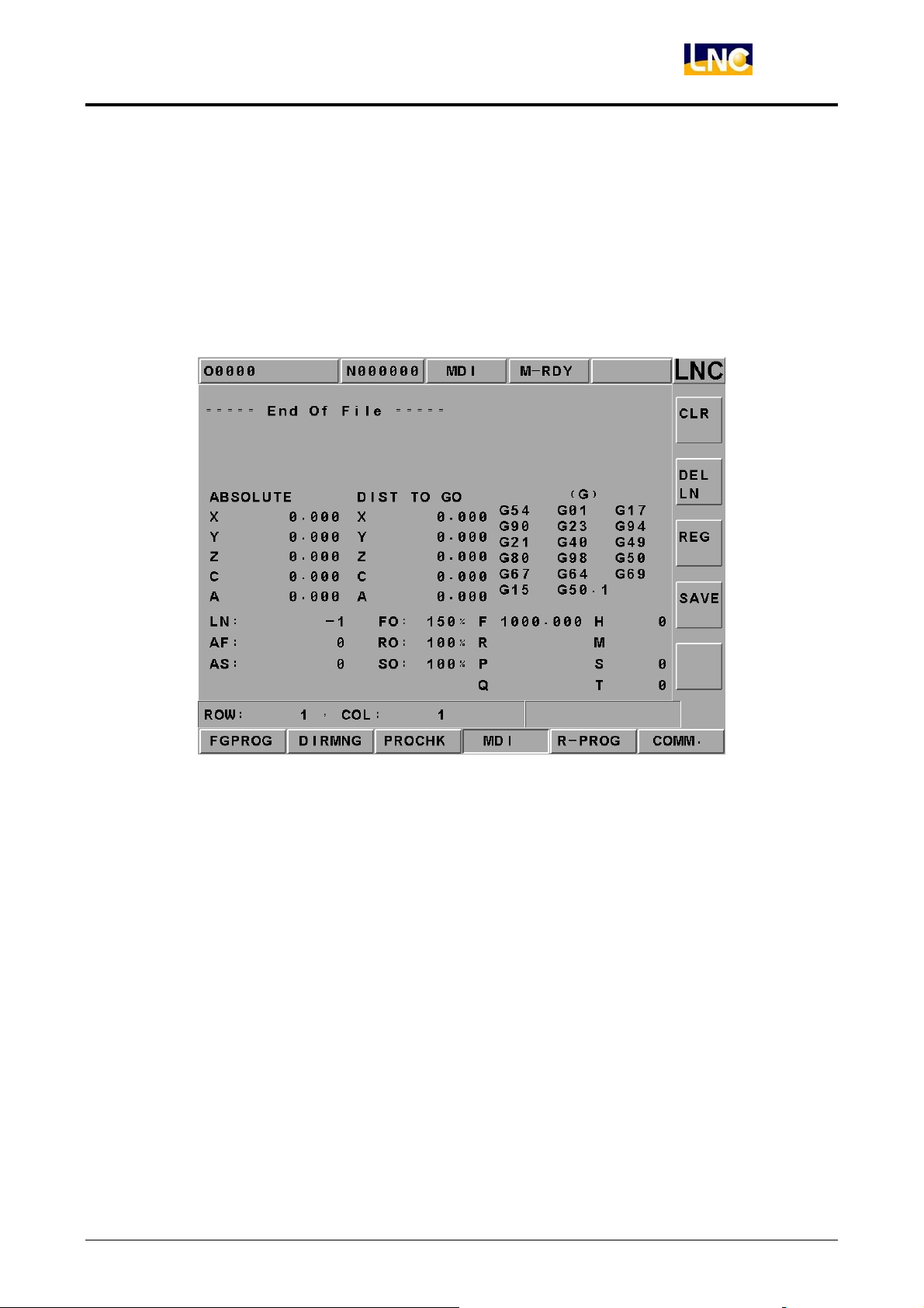
2.5.5 MDI
Pressing【MDI】key to entry into MDI page under MDI mode. User is to key-in a single
command block and then press <INPUT>. Then, the command will occur at the left section
of the main page. Then, pressing Cycle Start key and the command will be executed and
related data will be displayed. Using this method to do test running is more safe and more
time-efficiency.
Figure 2.5-20 MDI Page
LNC Technology Co., Ltd. 43
Page 49
LNC-M650
CNC Operation
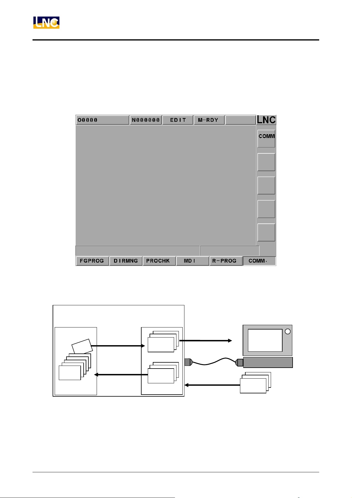
2.5.6 COMM (Communication of Files(RS232))
Clicking the【COMM】function button to receive and transmit programs between the
controller and other PCs. Operation and description of sub-function buttons 【COMM】 and
【SETT】are as following.
Figure 2.5-21 【COMM】Screen
CNC
Storage Device MMI
[Open]
File
File
Figure 2.5-22 Files Transmitting/Receiving Figure between Controller and Other PCs
[Save]
File
[Send]
[RS232]
PC
File
44
LNC Technology Co., Ltd.
Page 50
LNC-M650
CNC Operation
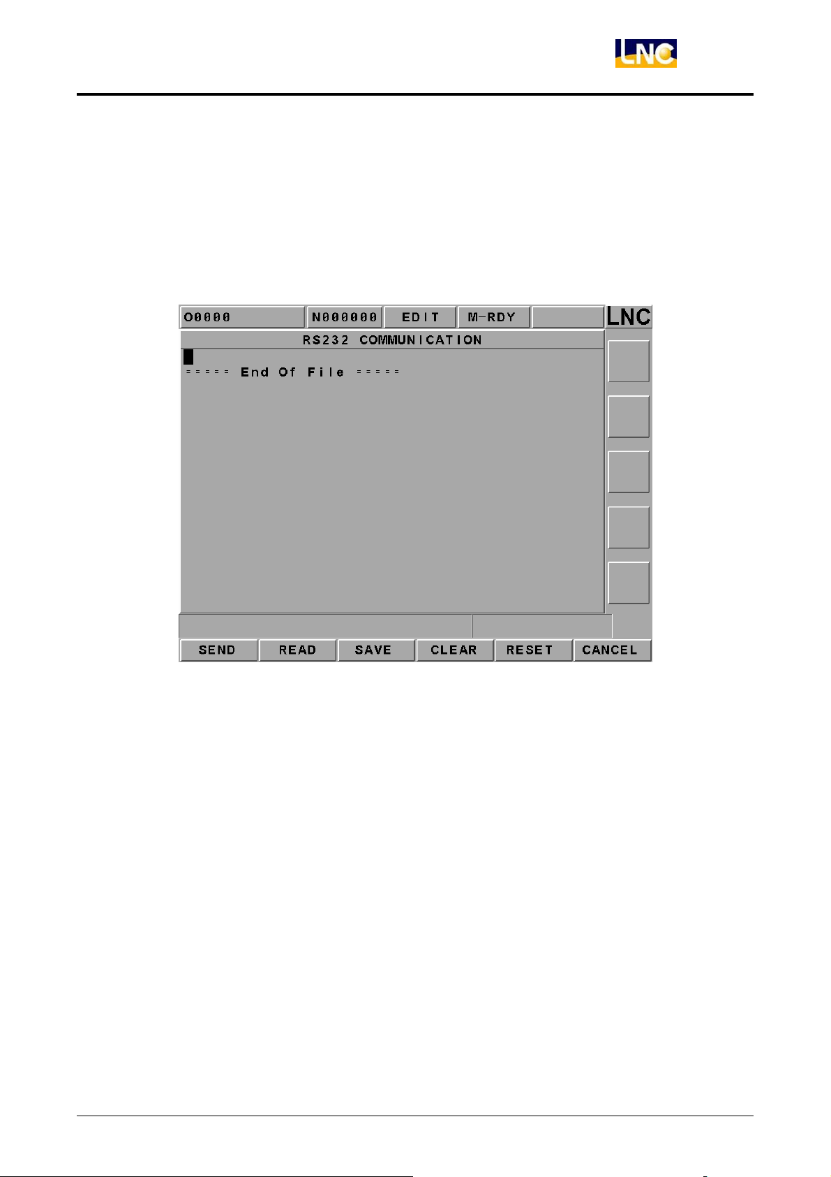
【Comm.】(Communication)
Users are able to executing RS-232 file transmitting (DNC), reading, saving, resetting and
other operations. Before using RS232 function, please confirm whether or not the
hardware connection is correct. Also, the setting of RS232 protocol and remote device
must be the same.
Figure 2.5-23 File Transmitting Page
LNC Technology Co., Ltd. 45
Page 51
LNC-M650
CNC Operation
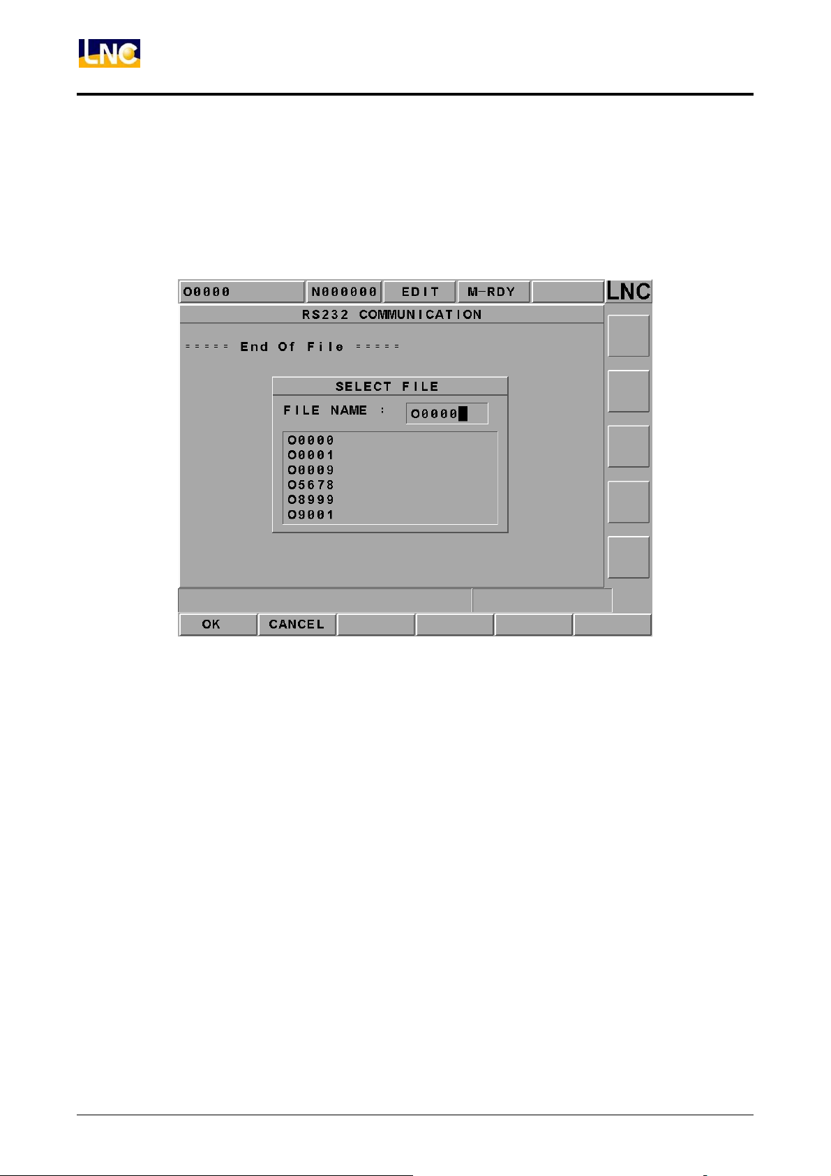
【SEND】
Users are able to executing RS-232 file transmitting (DNC), reading, saving, resetting and
other operations. Before using RS232 function, please confirm whether or not the
hardware connection is correct. Also, the setting of RS232 transmitting protocol and
remote device must be the same.
Figure 2.5-24 Selecting File Transmitting Function Page
【READ】
Before PC starts transmitting, must pressing this function key in order to let the system to
prepare to receive data.
46
LNC Technology Co., Ltd.
Page 52
LNC-M650
CNC Operation
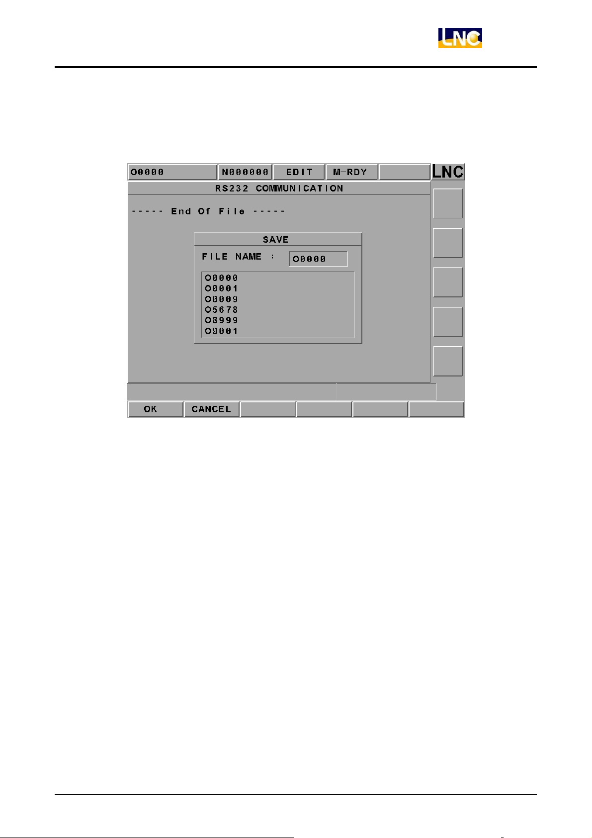
【SA VE AS】
When transmitting one program file to RS232 of the controller’s windows from outside,
pressing this key to select/key-in the storage path or file name directly.
Figure 2.5-25 Save File Function Page
【CLEAR】
Giving up and clearing program files in the windows.
【RESET】
Giving up file transmitting and resetting communication deal in order to build up connect
with RS232.
LNC Technology Co., Ltd. 47
Page 53
LNC-M650
CNC Operation
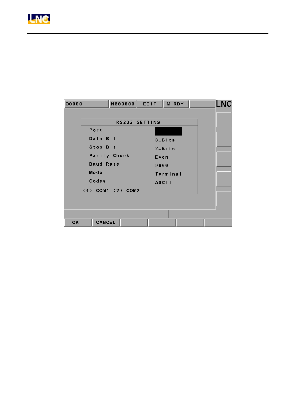
【RS232】
This screen provides the module setting of RS232. The setting at each side of the RS232
transmitting must be correct and the same in order to transmit (or so call DNC function)
correctly. Users are able to modify the transmitting deal for RS232 on this screen.
Figure 2.5-26 RS232 Setting
48
LNC Technology Co., Ltd.
Page 54

LNC-M650
CNC Operation
2.5.7 DNC Function
DNC function is a very useful function for CAD/CAM system users, especially the
controller is the controller used only (not the controller of PC BASED). Since the storage
memory capacity is not very big, so not possible to download all the programs at once,
which implies that it is very important for the DNC function to do its function while
transmitting. Since DNC program is doing its function while transmitting, so the controller
can’t edit it, neither using program calling nor using jump commanding. LNC Technology
Co., Ltd. already installed high capacity hard drive, therefore, users can transmit files into
the hard drive and then execute those files (this method is called the internal DNC method.)
The DNC function of executing its functions while transmitting is the other DNC method
(this method is called the external DNC method.) The above methods are very
convenience to use. The procedure is as below:
1. To set Controller and external PC as RS232 modal and to set the communication
protocol the same
2. To switch to EDIT mode
3. To press function button【COMM】in order to enable file windows and to set file
name as RS232
4. To switch to AUTO mode
5. To press “CYCLE START” button on OP Panel in order to transmit CNC waiting
program
6. To enable external PC to do RS232 file transmitting
7. To execute machine work automatically
LNC Technology Co., Ltd. 49
Page 55
LNC-M650
CNC Operation
2.6 OFFSET
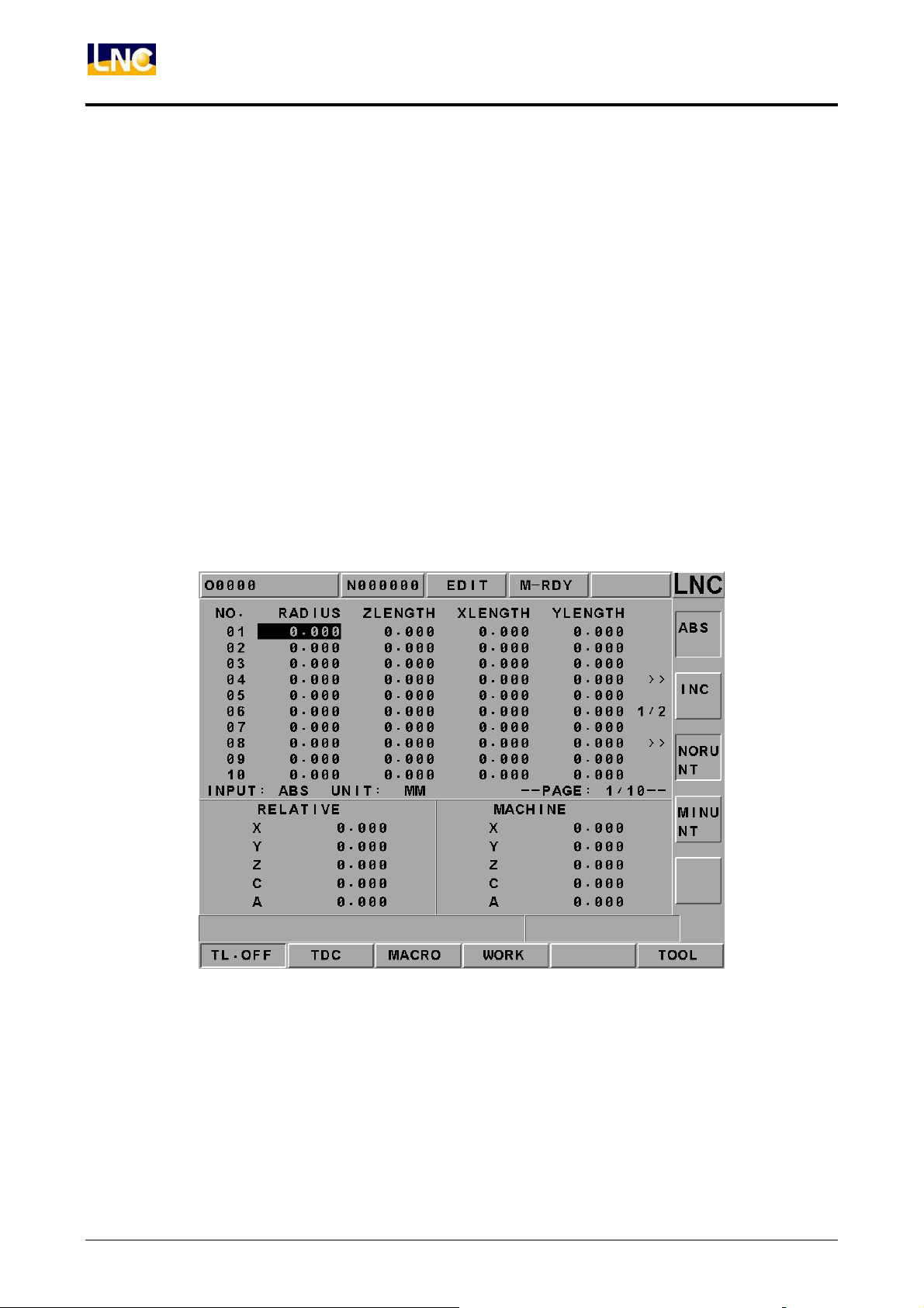
Pressing <OFFSET> to enter into the offset function screens such as 【TL. OFF】,
【MACRO】, and 【WORK】. Users are able to modify these settings under MDI mode or
machine ready mode.
2.6.1 TOOL OFFSET
Pressing 【TL. OFF】to enter into the below screen (Figure 2.6-1) and to key-in data
manually under MDI mode.
1. 30 sets of setting for Tool Offset. To switch the setting screen by using <PAGE↓> and
<PAGE↑> keys.
2. To move highlighter on the wanted setting numbers. To key-in the setting value in the
data enter rows and then to press <INPUT> key to write into the controller.
3. Absolute coordinate will change with tool offset everytime the part grogram uses one
tool offset number. The value is:
50
Figure 2.6-1 TL. OFF Screen
LNC Technology Co., Ltd.
Page 56
LNC-M650
CNC Operation
2.6.2 MACRO
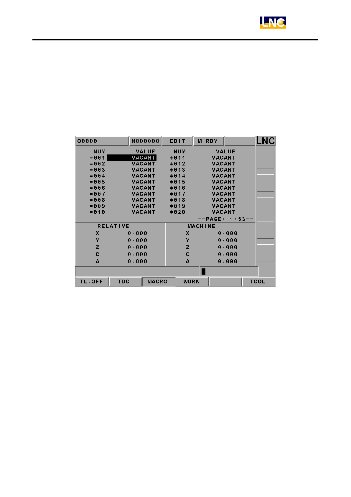
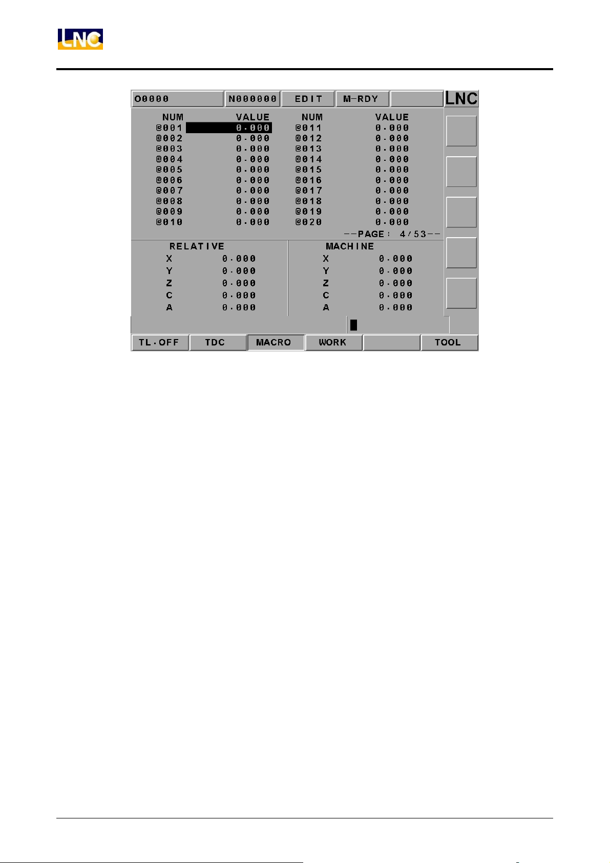
Pressing【MACRO】button to enter into the MACRO variable screen. In this function,
variables can be entered or modified. The modification method is to move the highlighter
to the wanted modify position and then to press <INPUT> key after entering the wanted
value. Variables that start with L are local variables and those start with C are common
variables. Please refer to MACRO chapter of program manual for a detailed description.
Figure 2.6-2 Local Variables of MACRO Variables
LNC Technology Co., Ltd. 51
Page 57
LNC-M650
CNC Operation
Figure 2.6-3 Global Variables of MACRO Variables
52
LNC Technology Co., Ltd.
Page 58

LNC-M650
CNC Operation
2.6.3 WORK
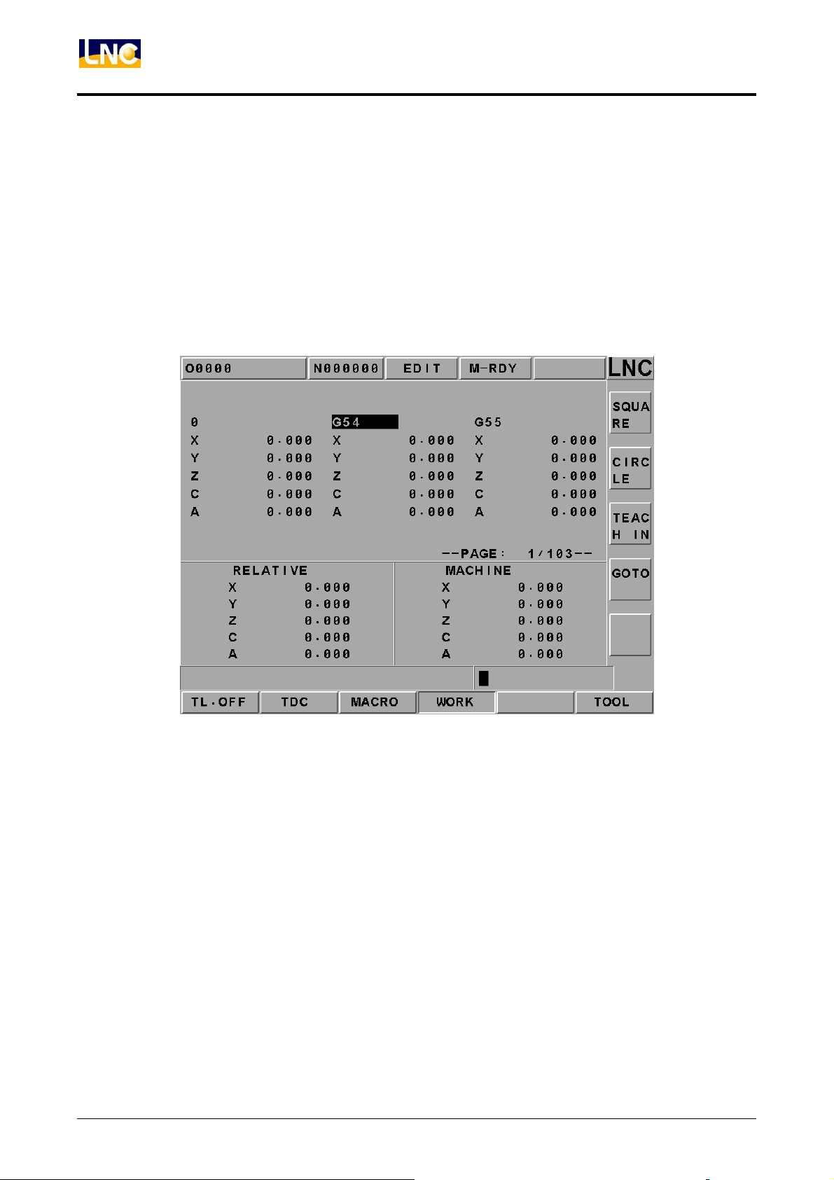
Pressing 【WORK】 button to enter into the working coordinate setting screen. In this
function, moving the highlighter to the wanted modify position and following the below
operation steps to execute setting.
Extend OFFSET setting will directly affect other 6 coordinate systems (G54 to G59). When
setting, please consider work piece coordinate, tool and program executing relationships.
# 01: G54 machine coordinate value of the reference point = #01 setting value + #(00)
setting value
# 02: G55 machine coordinate value of the reference point = #02 setting value + #(00)
setting value
# 03: G56 machine coordinate value of the reference point = #03 setting value + #(00)
setting value
# 04: G57 machine coordinate value of the reference point = #04 setting value + #(00)
setting value
# 05: G58 machine coordinate value of the reference point = #08 setting value + #(00)
setting value
# 06: G59 machine coordinate value of the reference point = #06 setting value + #(00)
setting value
1. The controller will provide7 sets of working coordinate system. Under MDI mode,
users can execute the following settings such as G54, G5, G56, G57, G58 and G59.
Also, using <PAGE↓> and <PAGE↓> key to switch screen.
2. Using direction keys to move cursor to the wanted change column and to key-in the
setting value Xxxx (i.e.:X100 or Z200 )in the enter rows. Then, the selected
coordinate value will be updated immediately by pressing <INPUT> key.
3. Key-in the axis name and the new coordinate value, users are able to write 3 axes
continuously. But, remember to put decimal point in order to prevent confusion.(i.e.,
X100. Z200.)
4. Set in the auto coordinate-gathering when the cursor is at G54~G59. So able to set
the present machine coordinate automatically in the part coordinate setting page:
LNC Technology Co., Ltd. 53
Page 59
LNC-M650
CNC Operation
SET X:Teaching in the X-axis machine coordinate value directly on the work coordinate
system where the cursor occurs.
SET Y:Teaching in the Y-axis machine coordinate value directly on the work coordinate
system where the cursor occurs.
SET Z:Teaching in the Z-axis machine coordinate value directly on the work coordinate
system where the cursor occurs.
SET ALL :Teaching in the three axes machine coordinate value of the present machine on
the work coordinate system where the cursor occurs.
Figure 2.6-4 Working Coordinate Setting Screen
54
LNC Technology Co., Ltd.
Page 60

LNC-M650
CNC Operation
2.7 Milling EASY-CAM
2.7.1 Preface
This function provides 2D pocketing work of one allowable island. The function area has
「Rough-Cutting」and「Fine-Cutting」working types. The CAM function in this controller
allows users to produce auto NC path for its pocketing of any Profile shape. It means that it
can define working piece’s geometry shape direction on the controller. Also, it will produce
the corresponding post NC code after setting the related working parameters.
2.7.2 Function Specification
Since this is a CAM system that is built inside the controller. In order to get the actual
balance of the calculation efficiency of the specification, there are some using restrictions
as below:
Only allow defining one closed Profile and it is limited inside the closed Profile. Only
can define maximum 6 islands.
The line/arch’s number of elements that are made by a single close profile and island
cannot be more than 100 sections.
Elements that are combined by Profile and Island must be closed.
Island must be surrounding by Profile. So, the island must be defined with the Profile.
Cannot have any intersect or self-intersect between islands. Also, cannot have any
point or line connecting/cutting between islands.
For profile and island, neither can have intersection nor have connection/cutting
between them.
The using pocking calculation method—Horizontal Surrounding(Arachnoids). As the
below figure.
Figure 2.7-1 Pocketing Calculation Method—Horizontal Surrounding
LNC Technology Co., Ltd. 55
Page 61

LNC-M650
CNC Operation
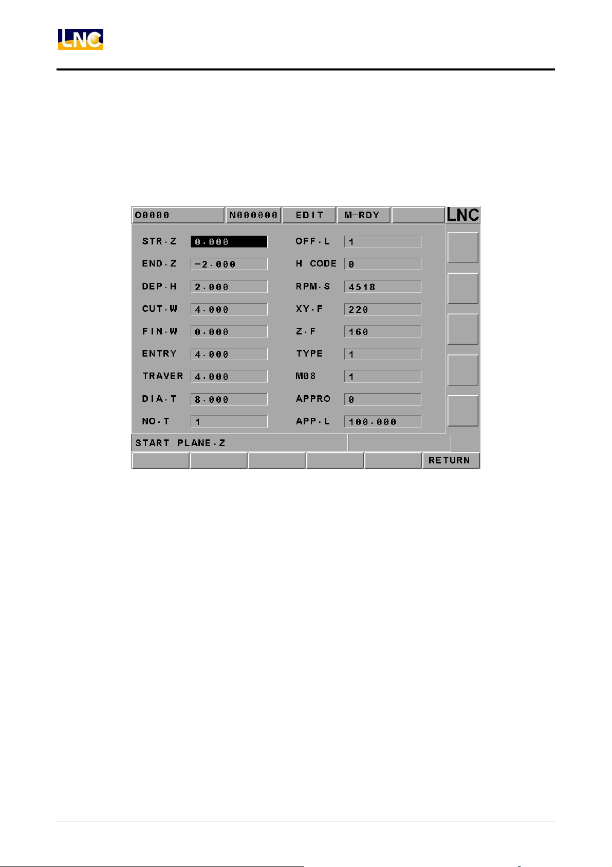
2.7.3 CUT PAR (Cutting Parameter)
For this CAM function, able to get the correct path program as long as the cutting
parameter setting is correct before path motion is executing. The definition of each
parameter is described below:
Starting Surface:The absolute Z coordinate program, which is used to assign the
starting cutting level.
Ending Surface:The absolute Z coordinate program, which is used to assign the
ending cutting level.
Cutting Width: Everytime’s feed amount on XY pane for the assigned tool. This value
should not be larger than the tool diameter.
Fine-Cutting Preservation Amount: the preservation amount for already-formed size
(for fine mill-cutting).
Feed Height:The absolute Z coordinate program, which is use to set the starting
point of mill-cutting. Tool will cut working part in G01 speed after arriving to the point in
G00 speed. So, the setting value of that point must be greater than [Starting Surface].
Moving Height:The absolute Z coordinate program, which is to set the ascent height
when tool working is switching position during mill-cutting procedure. Tool will cut into
the working part in G01 speed after arriving to the point in G00 speed. So the setting
value of this point must be greater than [Starting Surface].
Tool Diameter: This value must be greater than zero.
Tool Number: The timing codes (M06 T) when the designated tool is doing
tool-exchanging job, i.e., if this value is 1, M06 T01 will be produced.
Tool Length Offset:To choose tool length offset, setting 0 means to use the +ive
direction offset G43; setting 1 means to use –ive direction offset G44.
Offset Number:When tool offset, H machine structure is the replace code.
56
LNC Technology Co., Ltd.
Page 62
LNC-M650
CNC Operation
Spindle Rotational Speed:S machine structure means spindle rotational speed.
Flat Feed:F machine structure, define tool’s cutting feed rate is F when flat cutting.
Z-axis feedrate:F machine structure, is to define the cutting feedrate is F when
cutting toward Z-direction.
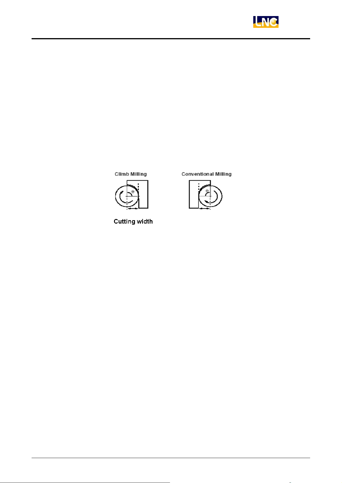
Climb/Conventional Cutting:To decide the cutting type of the tool path program.
Two cutting types are [Climb] and [Conventional]. [Climb] is used in rough-cutting and
[Conventional] is used in smooth-cutting.
Figure 2.7-2 Climb/Conventional Cutting Figure
Cutting Coolant:To decide whether or not to use the cutting function (M8).
Fine-Cutting Feed:To decide the Tool Approach type when doing [Fine-Cutting]. Two
types of fine-cutting feed which are vertical feed and arch feed. The preserve length
before vertical feed is the radius of the tool. The arch radius is the radius for the tool
feed.
LNC Technology Co., Ltd. 57
Page 63
LNC-M650
CNC Operation
2.7.4 Screen Operation Description
This system’s operation is divided into 4 types which are described as below:
PRJMNG
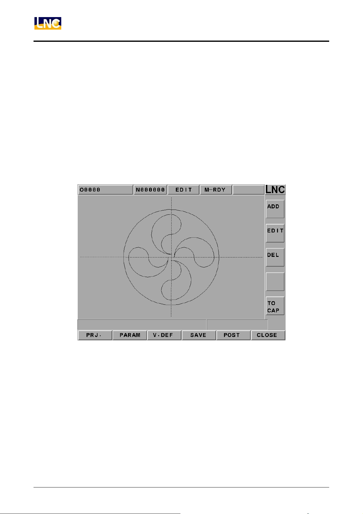
This function page provides adding/deleting/modifying/checking for profile and island.
When users want to add one profile or island, pressing adding button and then
choosing profile or island to enter into the profile configuration definition page. If want
to delete or modify the configuration, simply use the up/down of the direction key. The
chosen configuration will be indicated in red color. Please refer below as the related
screen:
Figure 2.7-3 Main Function Page
The above figure is an example that shows 4 islands in one profile (DEMOI). Able to
choose rough-milling and/or fine-milling in order to produce the related tool path
O9999 after pressing NC gear shifting button.
58
LNC Technology Co., Ltd.
Page 64
LNC-M650
CNC Operation
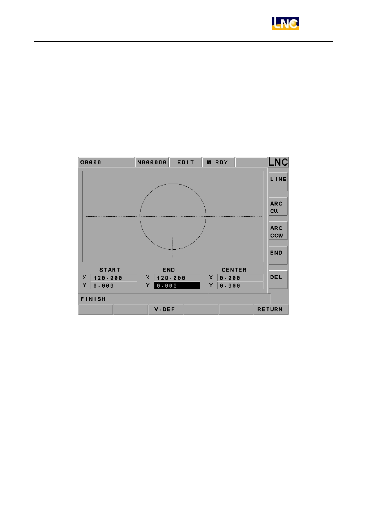
V. DEF
When users select a profile or island at the main function page, must use this page to
set the definition of this closed profile. Users must press the button at the right column
of the screen when doing the picture. One of Line, ARC CW, ARC CCW, END and
DEL will decide the type of the pixel. Since the definition of the profile must be closed,
so must enter the definition of the profile in order to connect from head to end.
Moreover, using the delete key from backward to forward. Please refer below as the
related screen:
Figure 2.7-4 Profile Definition Page
Note:For geometric pixel entering, LNC Technology Co., Ltd. Technology recommends
users to label the key position of each figure elements on the working figure first in
order to be more time-efficiency for entering time.
LNC Technology Co., Ltd. 59
Page 65
LNC-M650
CNC Operation
CUT PAR
This page is mainly to define the related CAM calculation and the output parameters.
For each column’s definition, please refer to the description of the related cutting
parameters. All parameter definitions must be reasonable before pressing [NC Gear
Shifting] button in order to produce the correct path program.
Figure 2.7-5 CUT PAR Page
Like the above Figure, it describes that this time’s production is to cut from Z=0 to
Z=-2 from the working face. Also, everytime’s cutting depth is 2mm, the tool diameter
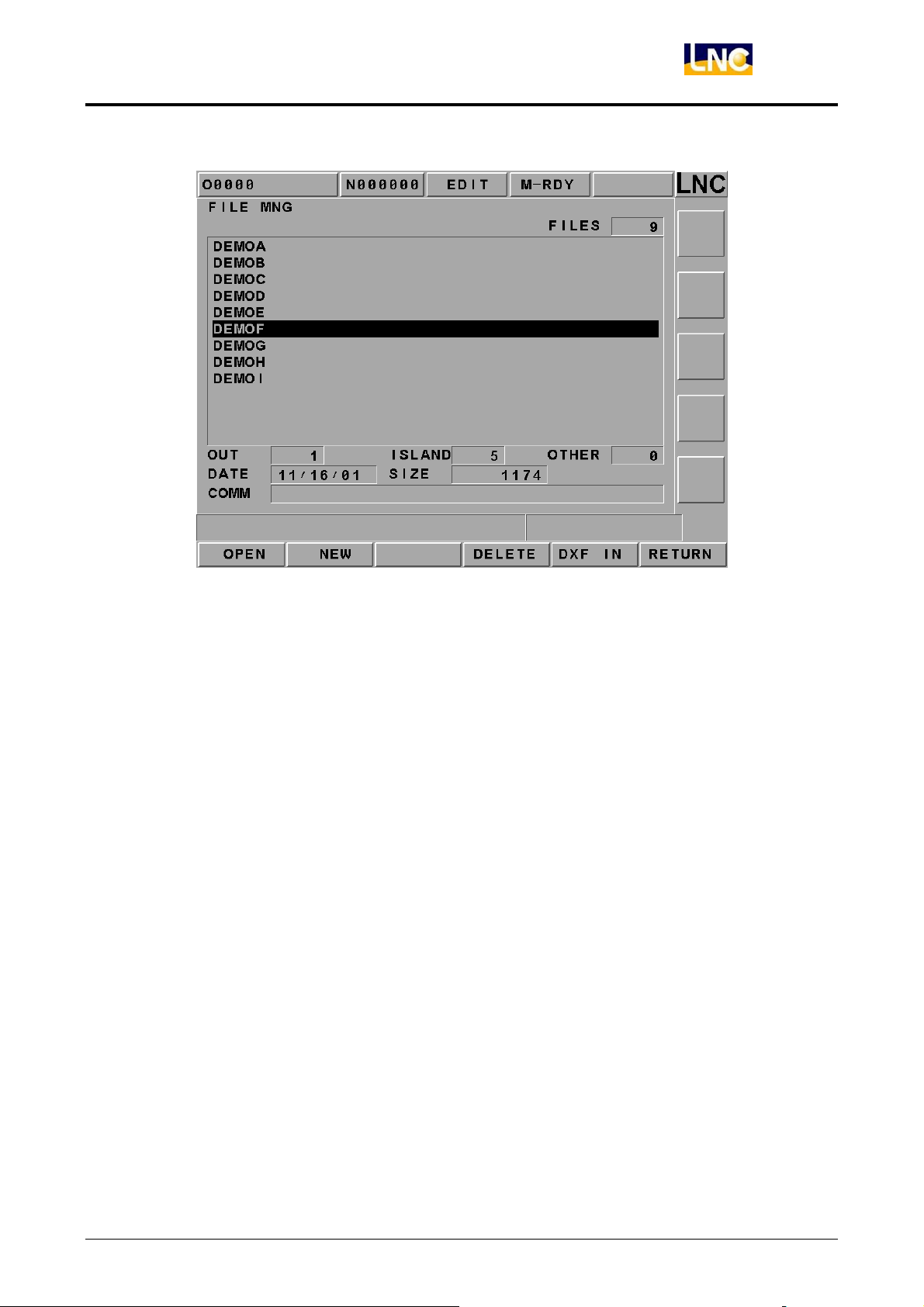
is ψ8, the cutting width is 4mm, the fine-cutting preservation width is 2mm and etc.
FILE MNG
This page provides the following functions such as new project file building, deleting,
opening old files and entering AutoCAD DXF files. Users must build a new file or open
an old one before doing this job, otherwise, the related operation will not be able to do
its job. Please refer below as the related screen:
60
LNC Technology Co., Ltd.
Page 66
LNC-M650
CNC Operation
Figure 2.7-6 FILE MNG Page
Pressing the UP/DOWN direction key to select the wanted file. The Left/Right direction
key can move the cursor to the [File Description] row and key-in the description for
that file. Users are able to import the DXF file into the new project file or the present
project file. Enter the new project file name into the entry row in order to import the
new project file. On the other hand, if not entering a new project name, then the file
will be imported into the present project file.
The following principles must be matched when AutoCAD is producing Figures:
AutoCADFigure shape must be AutoCAD R14 DXF(*.dxf)when choosing to import.
1. Figure shape entity must be LWPOLYLINE, even using plane command to draw
Figure.
2. Using color to differentiate profile or island. When definition is at
machine\mmibase.ini , default value is: DxfOutloopColor=5(Bleu, Profile),
DxfIslandColor =3(Green, Island).
3. No restrictions for the numbers of profile and island since they can be deleted
after importing.
4. Figure shape is okay to be non-close since it can be modified after importing.
LNC Technology Co., Ltd. 61
Page 67

LNC-M650
CNC Operation
2.8 MILLING FIGURE CONVERSATION
2.8.1 PREFACE
This function provides a G code structure that is easier to use. There are four working
methods: drill-machining, facing, side-cutting and pocketing. So users do not need to
remember complicate G code types and parameter definitions. Users only need to follow
the instruction of Figure Pane to key-in the related information. And then pressing gear
shifting button in order to produce the needed part program.
2.8.2 Function Specification
In order to have more elasticity for this function, so LNC Technology Co., Ltd. has
designed projects and production management structure. Also, the followings are some
restrictions due to the concern of the actual use:
Project name is D0000~D9999, totally 10000 units.
Every project allows having more than one production procedure. 99 production
procedures are the maximum.
Every project has one set of common parameters. Every production procedure has
one set of cutting parameter.
62
LNC Technology Co., Ltd.
Page 68
LNC-M650
CNC Operation
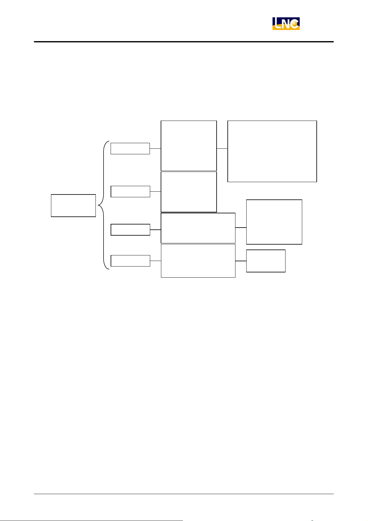
2.8.3 Work Production Selection
This function provides 4 types, totally 15 working methods. Also, there are total 47
combinations due to each type has different working styles. The working function structure
chart is as following:
Figure Style
Milling
Linear
Cycle
Drilling
Face-Milling
Side-Milling
Pecking
Figure 2.8-1 Working Function Structure Chart
Arch
Grid
Random
X Return
Y Return
X Single
Y Single
Cycle
Rectangular
Track Field
Cycle
Rectangular
Track Field
G73 High-Deep Peck-Drilling
G83 Separate Peck-Drilling
G85 Scissoring
G89 Bland-Scissoring
Inch/metric Rigid Tapping
Outer-Rough
Outer-Fine
Inter-Rough
Inter-Fine
Rough
Fine
LNC Technology Co., Ltd. 63
Page 69
LNC-M650
CNC Operation
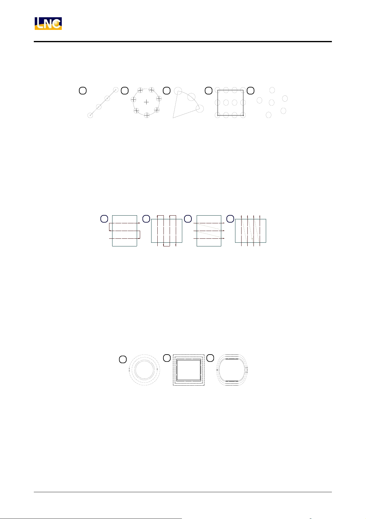
Drill-Machining:There are 5 working styles, which are G73, G83, G85, G89 and TAP. 5
working methods are as following:
1 2 3 4 5
Figure 2.8-2 Drill-Machining
1. Linear type orientation(G101),
2. Circle type orientation(G102),
3. Arch type orientation(G103),
4. Square type orientation(G104),
5. Random type orientation(G105).
Facing-milling: 4 working methods are as following:
1 2 3 4
Figure 2.8-3 Face-Milling
1. X-axis two directions surface(G111),
2. Y-axis two directions surface(G112),
3. X-axis single direction surface(G113),
4. Y-axis single direction surface(G114)
Side-Milling:there are 4 types of this working methods which are external rough-cutting,
external fine-cutting, internal rough-cutting, and internal fine-cutting. 3
working methods are as below:
1
2 3
Figure 2.8-4 Side-Cutting
1. Circular side-cutting (G121),
2. Square shape side-cutting(G122),
3. Tracking field side cutting(G123)
64
LNC Technology Co., Ltd.
Page 70

LNC-M650
CNC Operation
Pocketing:there are two working styles of this working methods which are rough-cutting
and fine-cutting. 3 working methods are as below:
1 2 3
Figure 2.8-5 Pocketing
1. Circular pecking(G131),
2. Square pecking(G132),
3. Run-way pecking(G133)
LNC Technology Co., Ltd. 65
Page 71

LNC-M650
CNC Operation
2.8.4 Common Parameters Setting
System parameters are arguments of G100 which are used in all production procedures in
projects. The description is as following:
Fixed Cutting Width: whether or not the cutting width is fixed while tool feeding: Yes:
1; No: 0.
Tool Diameter: tool diameter(mm). This value should be a default setting value. The
cutting parameter does not set the tool diameter so using this value as the standard.
Escape Value: Z direction escape height(mm).
Feed Speed: feed speed(mm/min). This value should be a default setting value. If
cutting parameter does not set feed speed, use this value as the standard.
Feed Ratio: setting the percentage ratio (%) of tool feed to tool diameter every times.
Spindle Rotational Speed: spindle rotational speed (rpm). This value should be a
default setting value. If the cutting parameter does not set the spindle rotational speed,
using this value as the standard.
2.8.5 Cutting Parameter Setting
The needed setting parameters and definitions are different due to different working
methods. Please refer to the description of arguments of the corresponding G code in the
program manual.
66
LNC Technology Co., Ltd.
Page 72
LNC-M650
CNC Operation
2.8.6 Operation Screen Description
This system’s operation is divided into 4 types and they are described as below:
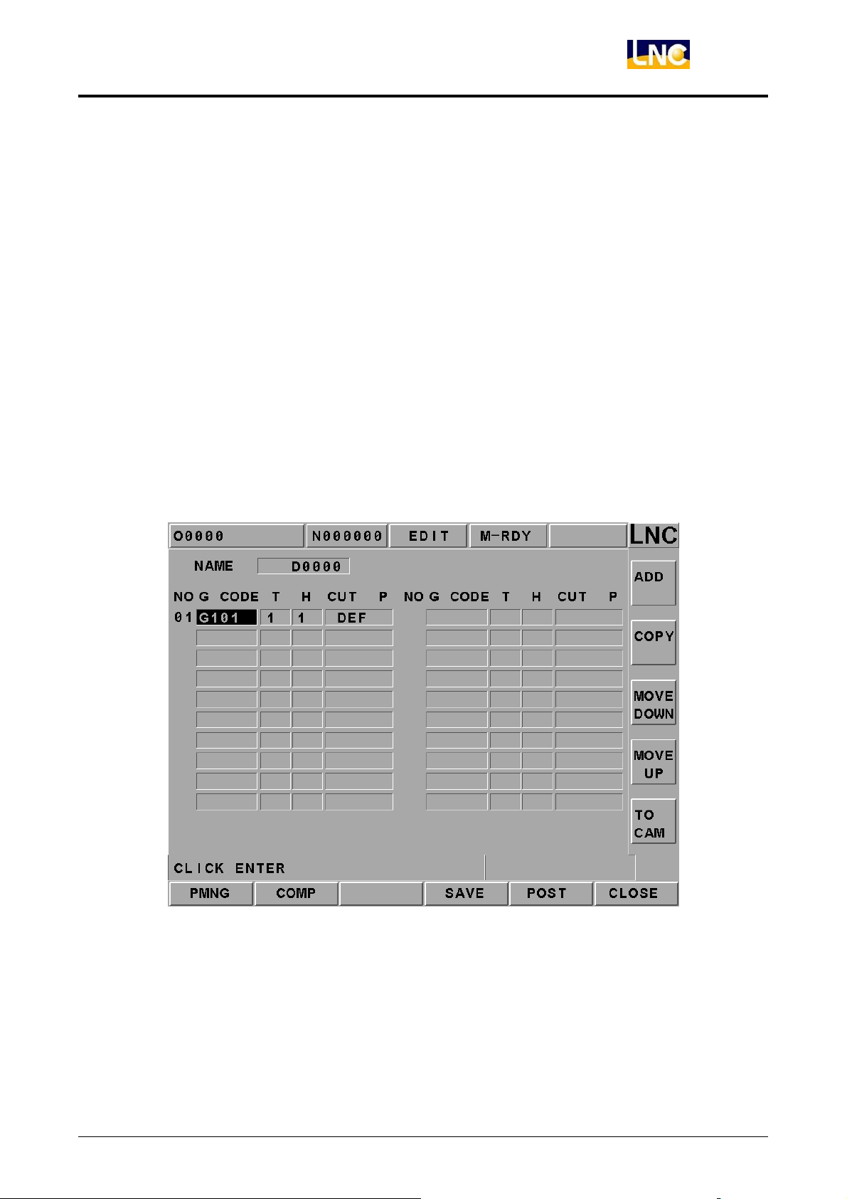
PMNG
This function page mainly provides add/delete/modify/check for production and
procedure and save/gear-shifting and exit for projects. Every production procedure
must edit 4 items. Tool number and compensation can be inputted directly. G code
and cutting parameter can continue editing after clicking the input key. Since
CAD/CAM and figure transmitting are in the same function group, so screen is able to
switch to CAD/CAM editing page by pressing CAM button. Please refer below as the
related screen.
Users can use the direction key up/down to move the yellow cursor and also to decide
the wanted editing production procedures or items. The delete key (del) can delete the
production procedure at the row where the yellow cursor occurs.
Figure 2.8-6 PMNG Page
LNC Technology Co., Ltd. 67
Page 73
LNC-M650
CNC Operation
PMNG
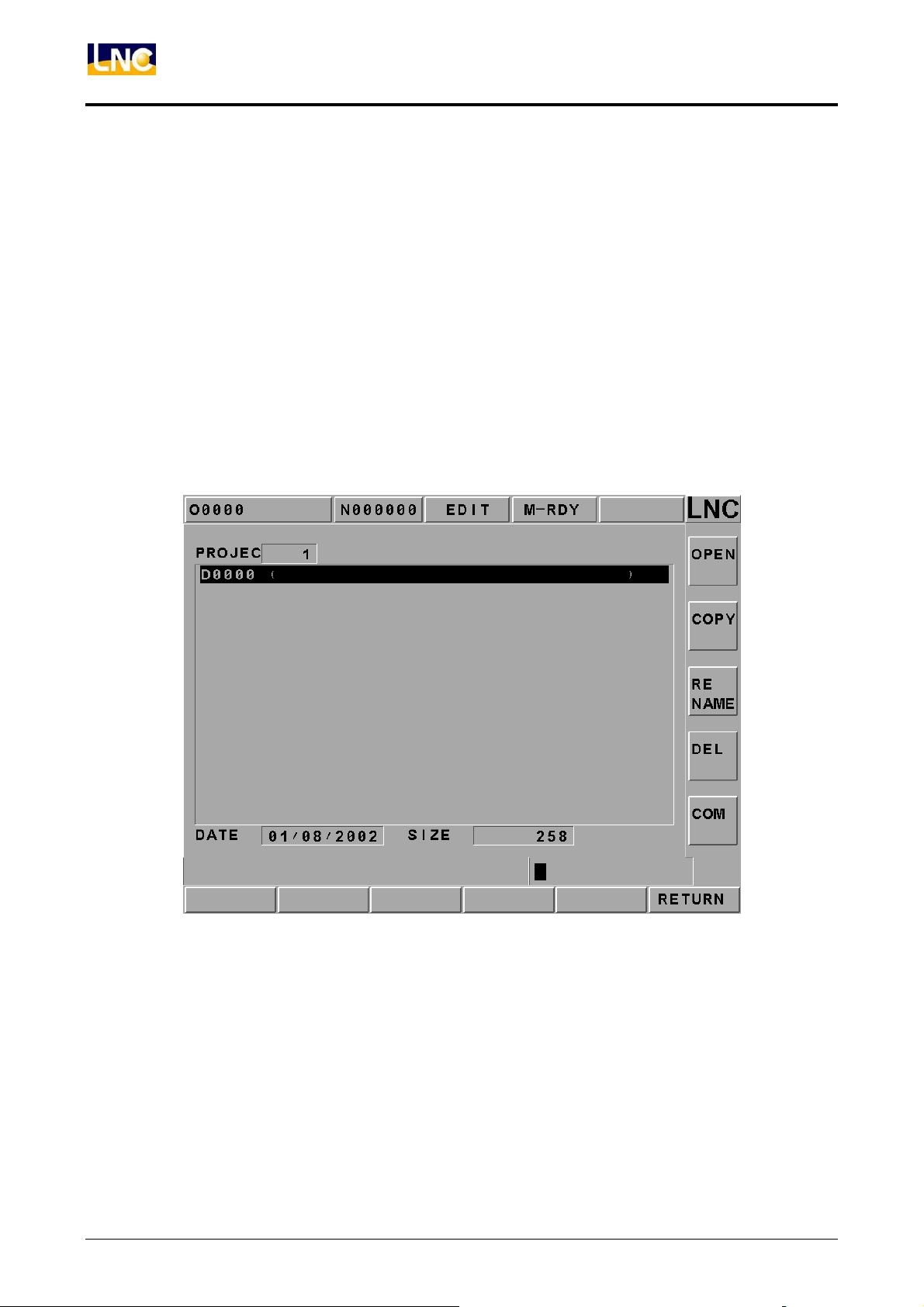
This function page mainly provides open, copy, rename, delete and note for projects.
All operating methods are to key-in data before clicking on function keys expect
opening files. If key-in a new file name, then a new file will be opened. Otherwise, the
system will open the file that is in the file list where the yellow cursor occurs. Return
button is to switch back to the figure transmitting main function page. Note: please
open the file at that page before start editing at the main function page. Please refer
below for the related screen.
Users not only can use the up/down key to move the yellow cursor but also use the
pgup/pgdn key to do extensively moving. The notice display of the file is within the
bracket of the file list.
68
Figure 2.8-7 PMNG Page
LNC Technology Co., Ltd.
Page 74
LNC-M650
CNC Operation
COMP
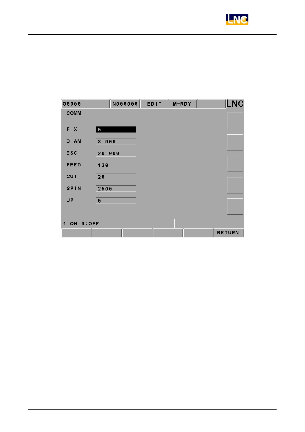
This page’s main function is to set the local parameters of all project production
procedures. Pressing return button will be able to switch back to the main function
page of the figure transmitting after complete setting. Please refer below as the
related screen:
Figure 2.8-8 COMP Page
LNC Technology Co., Ltd. 69
Page 75
LNC-M650
CNC Operation
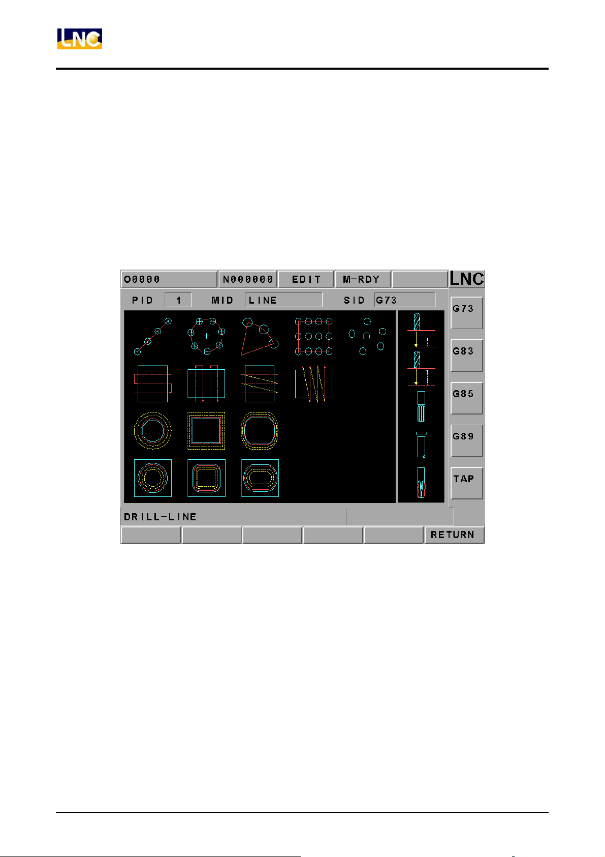
G Code Selection Page
This page’s main function is to select working method. Pressing the return button to
switch to the figure transmitting main function page after selecting.
Please refer below as the related screen.
Using the direction keys up/down/left/right to move the yellow square before pressing
the function button at the right side in order to complete the selecting motion. The
figure at the right side and the function buttons will be different according to the item in
the yellow square at the left side.
70
Figure 2.8-9 G Code Selection Page
LNC Technology Co., Ltd.
Page 76
LNC-M650
CNC Operation
CUT PARAM
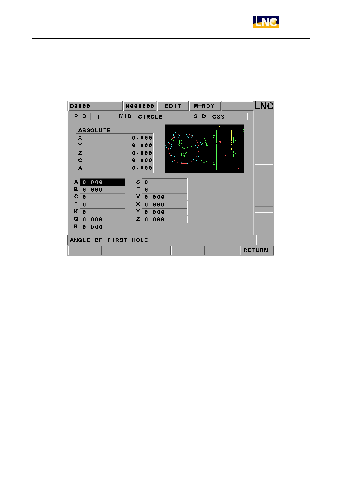
This page is mainly to set the cutting parameter of a single production procedure in a
project. Pressing the return button to switch back to the figure transmitting main
function page after complete setting. Please refer below as the related screen:
Figure 2.8-10 CUT PARAM Page
Users only need to use the figure shape reminding at the upper right side and then to
key-in the related information in order complete setting. When the setting column is
the diameter (Parameter # T), a function key as “T Set” will occur. The function button
is to key-in the 2 times of the radius compensation value of the corresponding tool
number at the OFFSET page into this column according to the setting tool number at
the main function page.
LNC Technology Co., Ltd. 71
Page 77
LNC-M650
CNC Operation
2.9 GRAPH
2.9.1 Function Introduction
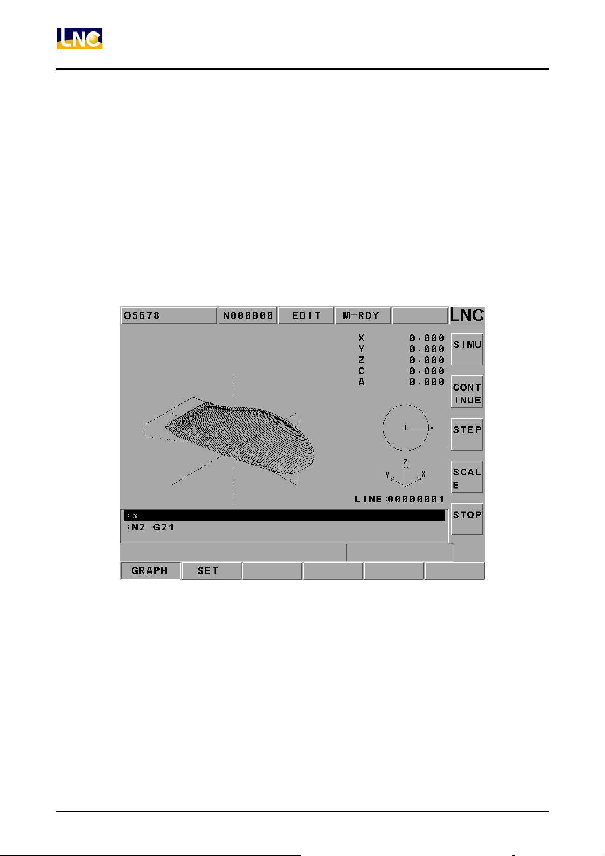
Pressing 【GRAPH】 to enter into this function group. The present working path and that of
the preview programs will occur in【GRAPH】screen. Users are able to set the view angle
and the display range of the path display in【SET】screen.
2.9.2 GRAPH
The path display screen is as the below Figure. Coordinate value that is displayed at the
upper-right side is the absolute coordinate of the present tool position. Lower-right side
displays the coordinate view angle
Figure 2.9-1 GRAPH Screen
Note 1: Cursor is green color, G00 is red color and G01, G02 and G03 are yellow color.
Note 2: Cursor is green color, G00 is blue color, and G01, G02, and G03 are pink color.
Center line is bright-green color.
72
LNC Technology Co., Ltd.
Page 78
LNC-M650
CNC Operation
2.9.3 SET
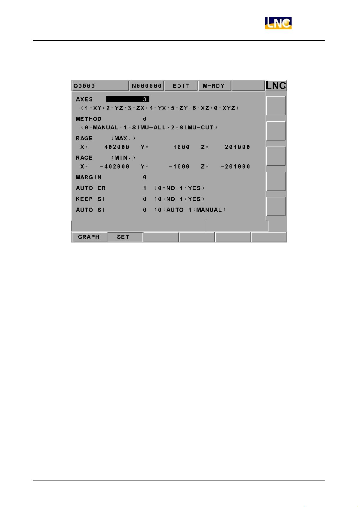
Figure 2.9-2 Main Screen of the Windows Definition
Drawing Surface: the using coordinate view angles are (1=XY, 2=YZ, 3=ZX, 4=YZ,
5=ZY, 6=XZ, 0=XYZ)when key-in into the path display screen.
Setting Method:the drawing range of the entering 【SET】screen (0=manual, 1=
preview result-full travel, 2= preview result-cutting travel).
0 manual:preview the drawing range as the reading manual setting’s max/min
values.
1 preview result full traveling(including moving path): preview the
drawing range as the reading part program path’s max/min values, the smallest
value.
2 preview resultcutting traveling(only including cutting path): preview
the drawing range as the max and/or min values of the reading cutting path, the
smallest value.
LNC Technology Co., Ltd. 73
Page 79

LNC-M650
CNC Operation
Drawing Range (max):setting to use the manual method to draw the largest value of
X, Y, and Z axes range.
Drawing Range (min):setting to use the manual method to draw the smallest value
of X, Y, and Z axes range.
Preserve Border:setting the preservation value for【SET】screen border.
Auto Delete:assumed under the condition of not executing program preview. Users
are able to choose whether or not to delete the previous path display screen when
enable cutting function while the machine is doing the path display(0= Not Delete,
1=Auto Delete).
74
LNC Technology Co., Ltd.
Page 80
LNC-M650
CNC Operation
2.10 DGNOS
Pressing <DGNOS> and 6 main function screens occur, which are 【 ALARM 】 ,
【SYSUPD】, 【IOCSA】, 【MLC2】, 【SYSTEM】 and 【CIRCUL】. Users are able to
know the condition of HMI signal and machine condition from the DGNOS function screen
in order to do the maintenance and the system testing.
2.10.1 ALARM
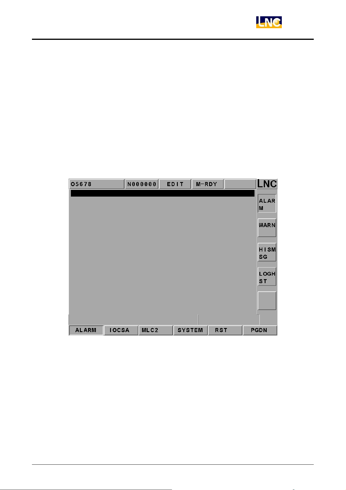
Clicking【ALARM】to enter into the 【ALARM】, 【WARN】, 【HISMSG】 and
【LOGHST】. When there is any alarm message or warning message from MLC, the alarm
message will occur on the screen. Users can use this screen to remove any irregular
condition of the controller.
Figure 2.10-1 ALARM Message Screen
【ALARM】
Alarm message will occur when there is any problem in system running. This will make the
system stop running and also will display the alarm message on the screen. When the
problem is solved, must press <RESET> in order to release the situation.
LNC Technology Co., Ltd. 75
Page 81
LNC-M650
CNC Operation
【WARM】
Warning message is decided by matching with the design of the MLC LADDER. Example
is when the safety door is not closed completely, LADDER program will send out “DOOR
NOT CLOSE” message. Or, when the Coolant Supply is broken, then the message
“COOLANT LAW” message will be sent out.
So when the alarm message occurs, please check the conditions of machine and
peripheral equipments according to the LADDER program. The system will stop running
when the system sends out the warning message and the warning message will be
displayed on the screen. When the problem is solved, must press <RESET> to release the
warning.
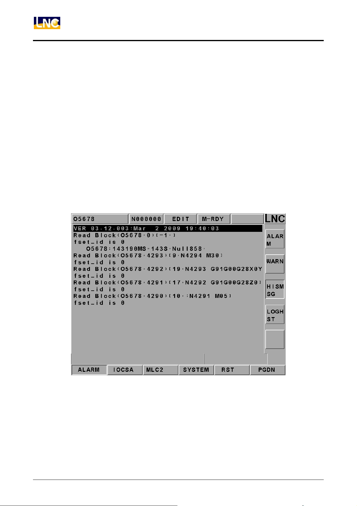
【HISMSG】
System version and program debugging message will occur. This page displays the
system current running condition.
76
Figure 2.10-2 Message Page
LNC Technology Co., Ltd.
Page 82
LNC-M650
CNC Operation
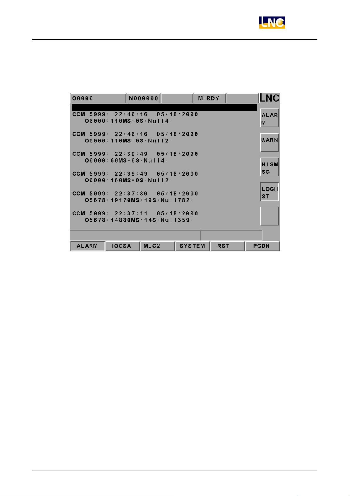
【LOGHST】
Able to display all records of alarm/warn and the records will not disappear even if alarm/
warn reasons are cleared.
Figure 2.10-3 LOG History Page
LNC Technology Co., Ltd. 77
Page 83
LNC-M650
CNC Operation
2.10.2 IOCSA
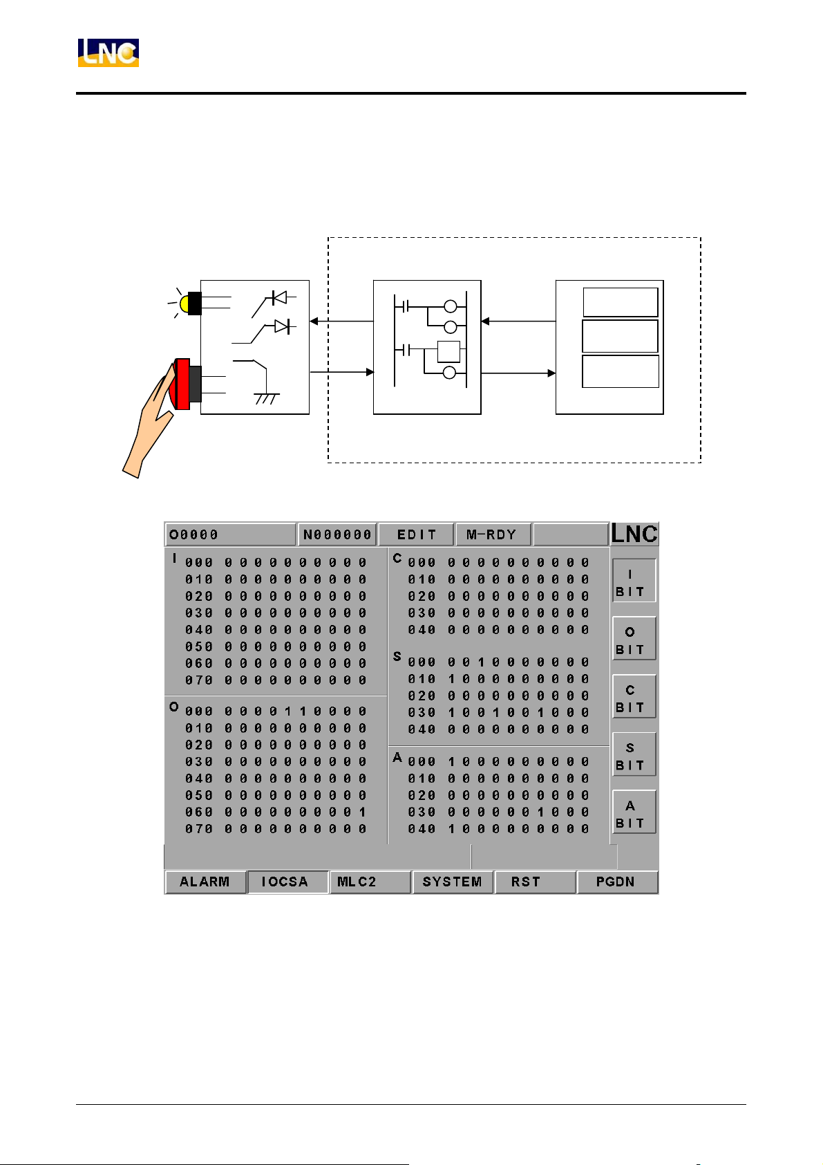
【IOCSA】 is to check the screen of the I/O or system internal condition which including I,
O, C, S, A.
OP Panel
MLC (Ladder Program)
O
I
Figure 2.10-4 I/O or Internal Condition
C
S
CNC
Register
Timer
Counter
78
Figure 2.10-5 IOCSA Main Screen
LNC Technology Co., Ltd.
Page 84
LNC-M650
CNC Operation
This screen is divided into 5 parts. The assigned method of the focus point is to assign via
sub-function button. The assigned type is displayed on the upper left column of the screen
(Using the above Figure as an example. Pressing the sub-function button 【I BIT】, the type
will be displayed at the upper left column of the screen.); < PAGE↑> and
< PAGE↓> keys are used to control the page changing of this【I BIT】sub-function.
2.10.3 PLC2
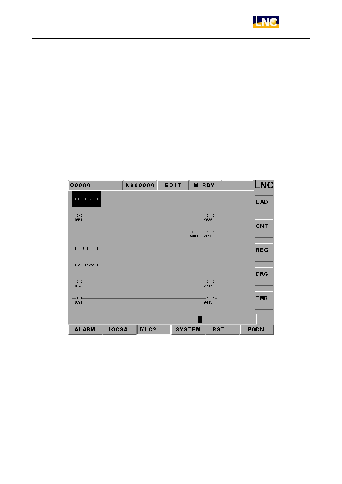
Pressing 【MLC2】 and the main function key screen is as below. Users will see 【LAD】,
【CNT】, 【REG】, 【DRG】, and【TMR】functions.
Pressing【LAD】and the screen is as below:
Figure 2.10-6 LADDER Figure
Users are able to add number on the wanted searching English characters, such as I, O, C,
S, A, R, TM and est. in 【LAD】 entering row. Pressing 【INPUT】 to start searching the
position of those characters. For example: key-in TM001 or TM1 to search for the position.
LNC Technology Co., Ltd. 79
Page 85
LNC-M650
CNC Operation
2.10.4 SYSTEM
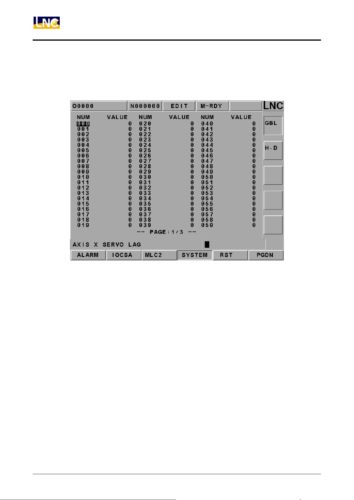
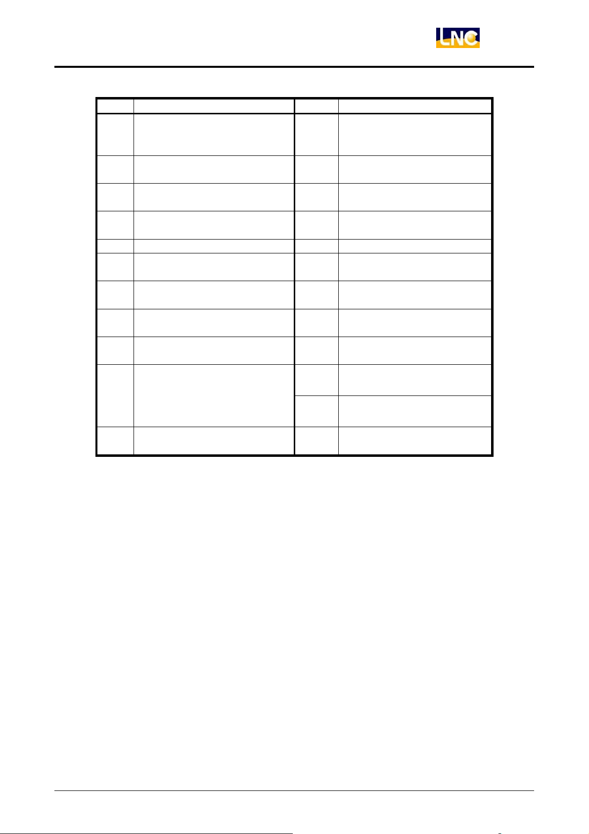
Pressing【GBL】and the screen is as below. (System data is to display screen of the
system maintenance variable. This function is for designers and technical people to use.)
Figure 2.10-7 System Data\System
80
LNC Technology Co., Ltd.
Page 86
LNC-M650
CNC Operation
# Definition # Definition
X-axis servo lag counting
0
value
Y-axis servo lag counting
1
value
Z-axis servo lag counting
2
value
4th-axis servo lag counting
3
value
16
17
18
19
X-axis hand wheel
command
counting value
Y-axis hand wheel
command counting value
Z-axis hand wheel
command counting value
C-axis hand wheel
command counting value
4 Waiting MST to ready signal 20 BLOCK times
5 In Position Checking 32
Actual spindle rotational
6
speed
Spindle servo lag counting
7
value
33
34
8 Spindle commanding value 35
Actual X-axis machine
coordinate value
Actual Y-axis machine
coordinate value
Actual Z-axis machine
coordinate value
Actual 4th-axis machine
coordinate value
9 Angle of spindle orientation
Spindle orientation arrival
10
range PLUSE
36 Index ISR Counter
38 ISR Counter
39
Distance between present
Spindle position to index
LNC Technology Co., Ltd. 81
Page 87
LNC-M650
CNC Operation
【H.D.】
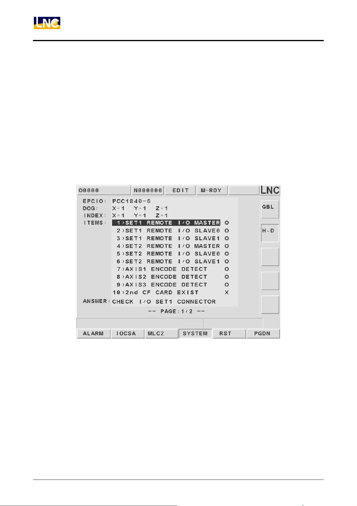
There are 9 items in the diagnosis function item. These function items are to check
whether or not the connection cable from motion card to I/O card is connected. Or,
checking whether or not the Jump position is correct. If the question mark (?) changes to
across (X) after diagnosis on the right windows side, it indicates this item has error. Users
are able to get the possible error message from the solving method in order to check and
to solve the problem.
The HOME DOG condition at the top of the windows indicates that if the value of each axis
is 1, the present position of each axis is on the HOME DOG.
82
Figure 2.10-8 SYSTEM\H.D.
LNC Technology Co., Ltd.
Page 88
LNC-M650
CNC Operation
2.10.5 Working Parameter Page
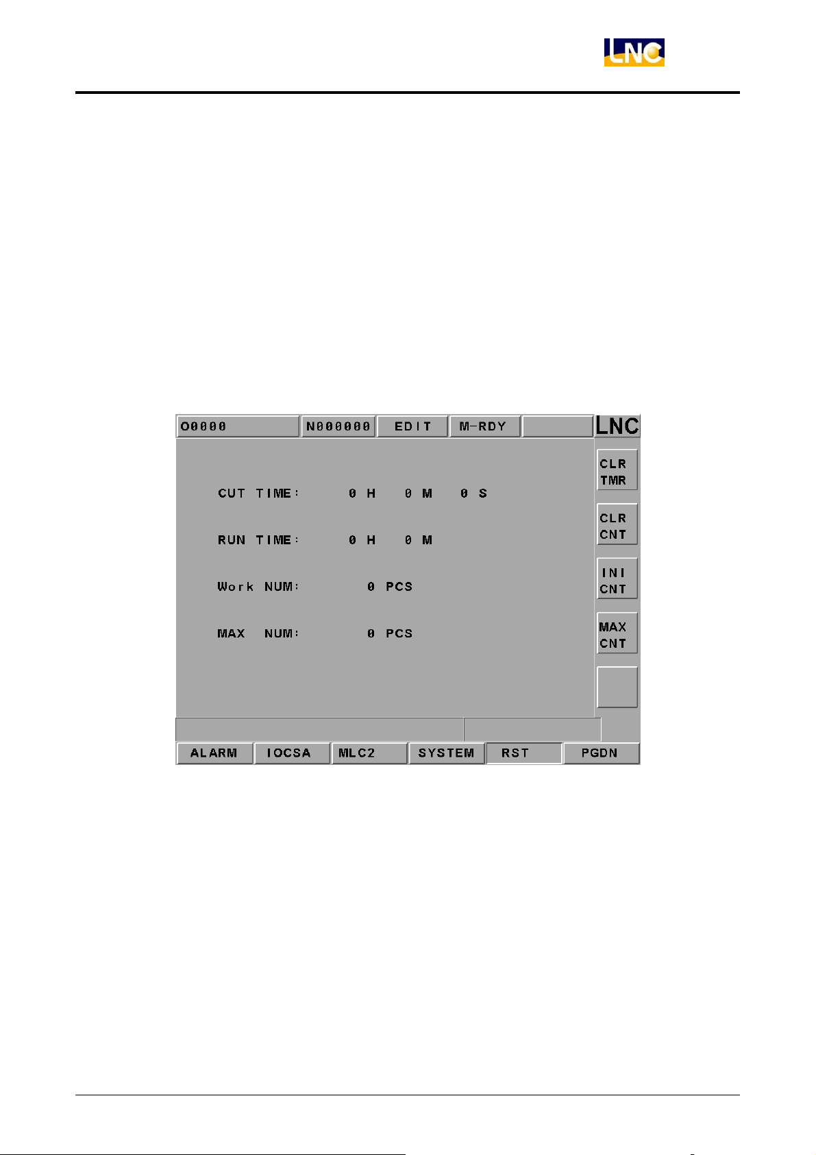
Cutting Time:When users press “Cycle Start” button on OP, cutting time will reset to zero
and then start timing until the part program finishes.
Working Time:Working time is the sum of cutting time everytime rebooting. It will be set
to zero until exit (returns to zero). Using 【RST】 + 【RUNTIME】 will
return the working time back to zero immediately.
Working Piece:When CNC has read M02, M03 or other M codes, the system will adding
up the working piece automatically. Using 【RST】 + 【PARTCONT】 will
return the working piece number back to zero.
Figure 2.10-9 Working Parameter Page
LNC Technology Co., Ltd. 83
Page 89
LNC-M650
CNC Operation
2.10.6 SYSUPD
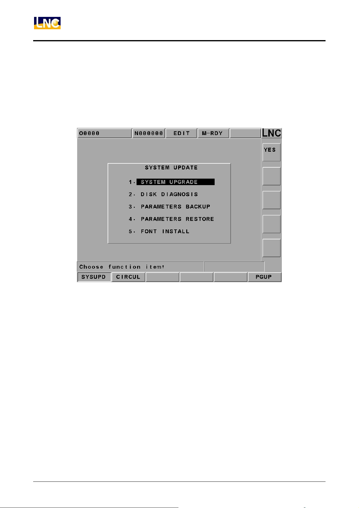
This function can be executed only under that condition that CNC is not ready. Please
pressing【SYSUPD】button after pressing the EMG-STOP key. At this time, a screen which
function is selected by the cursor (like Figure 2.10-3) will occur. This screen allows users
to select the wanted working item. Each function is listed as below:
Figure 2.10-10 System Upgrade Screen
84
LNC Technology Co., Ltd.
Page 90
LNC-M650
CNC Operation
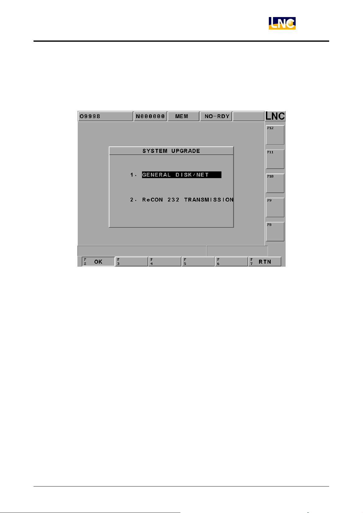
SYSTEM UPGRADE
Please install LNC Technology Co., Ltd. newest version software if choosing this function.
Pressing【YES】, the installation screen will occur. There is installation program instruction
during installation so only need to follow the instruction to upgrade the system.
Figure 2.10-11 SYSTEM UPGRADE
LNC Technology Co., Ltd. 85
Page 91
LNC-M650
CNC Operation
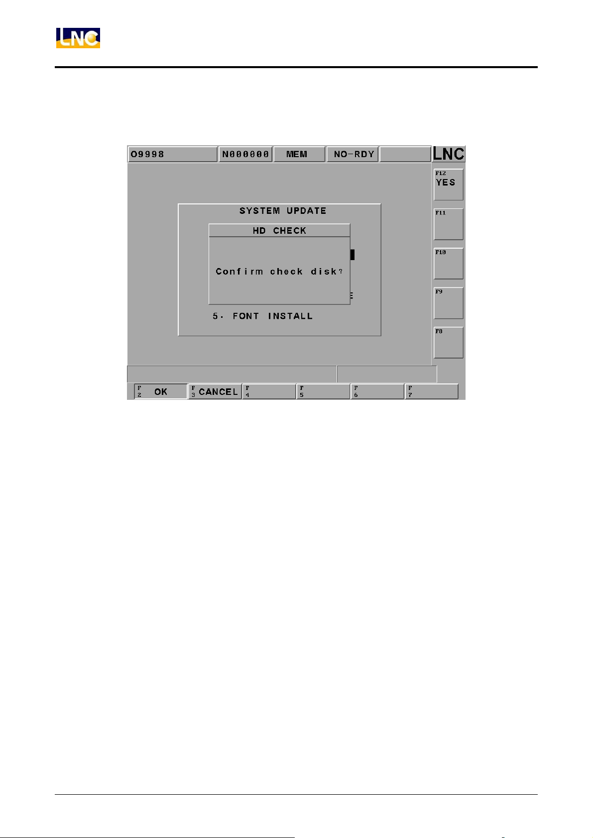
H.D CHECK (DISK DIAGNOSIS)
Selecting this function, a confirm dialog box will occur.
Figure 2.10-12 Confirm Whether or Not to Do the Hardware Checking
86
LNC Technology Co., Ltd.
Page 92
LNC-M650
CNC Operation
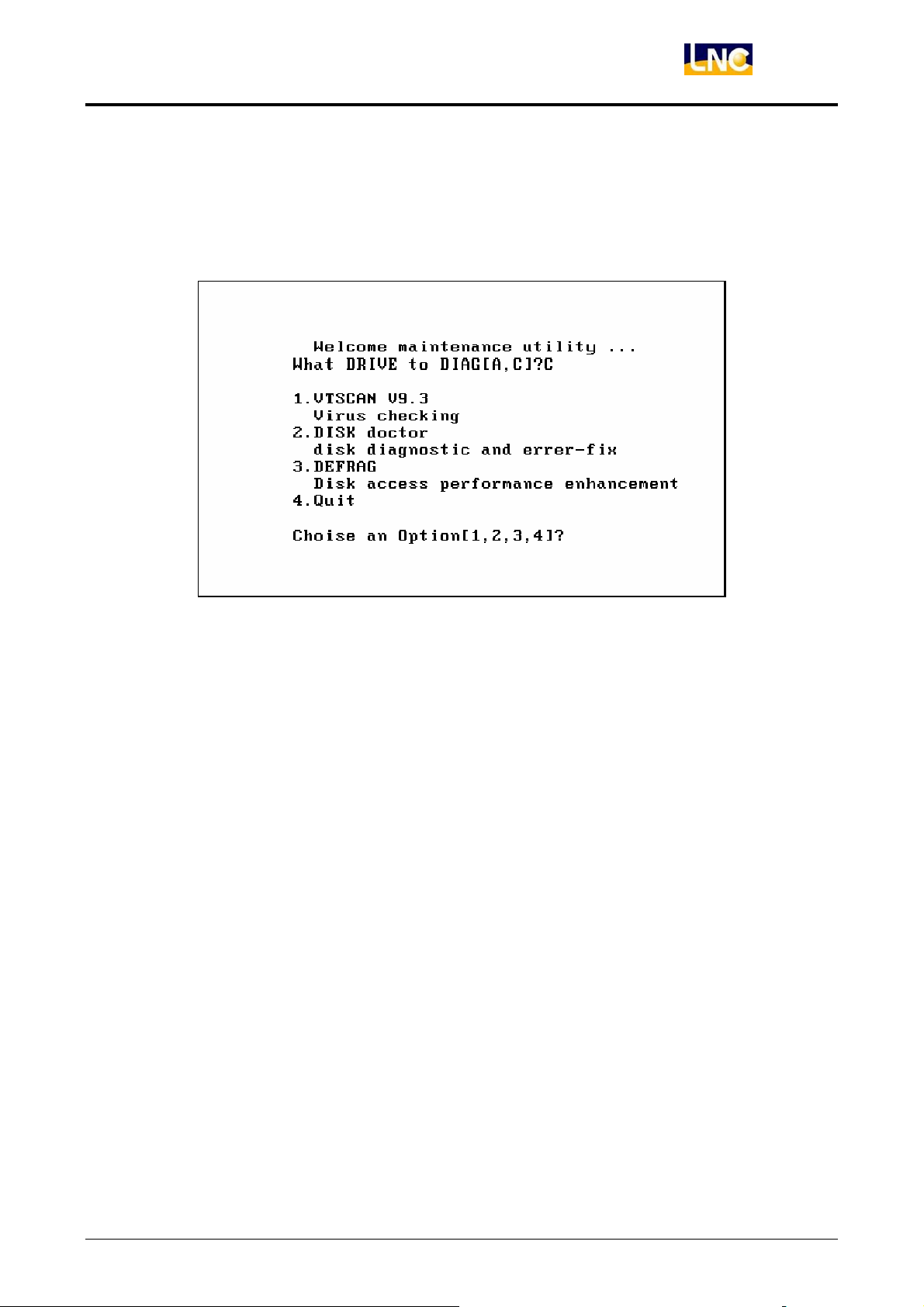
Pressing the confirm button to return back to DOS mode . Users are able to choose to use
A drive or C drive. If users do not choose, the system will use the default C drive. There
are 4 types of working items for users to choose:
(1).anti-virus (2).hard drive scanning (3).hard drive reset (4).exit
Figure 2.10-13 Hardware Checking Function Selection
LNC Technology Co., Ltd. 87
Page 93
LNC-M650
CNC Operation
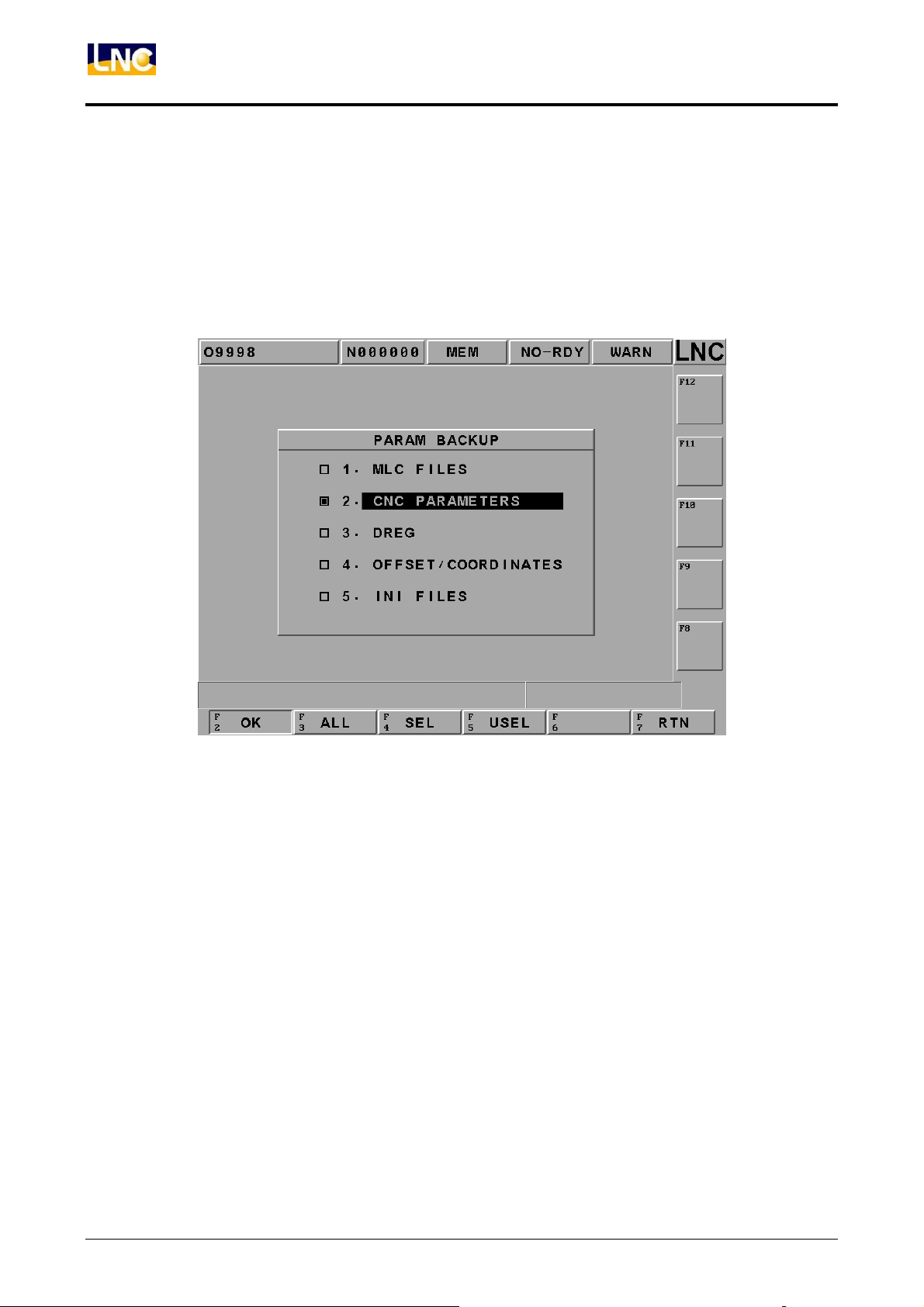
PARAM BACKUP
The below dialog box will occur when choosing this function. Users are able to choose the
wanted backup parameter item. Users are able to key-in the dialog box of the backup copy
path after pressing the confirm button. Pressing the confirm button after users key-in or
select the wanted backup parameter to complete the parameter backup function.
Figure 2.10-14 PARAM BACKUP Selection Screen
88
LNC Technology Co., Ltd.
Page 94
LNC-M650
CNC Operation
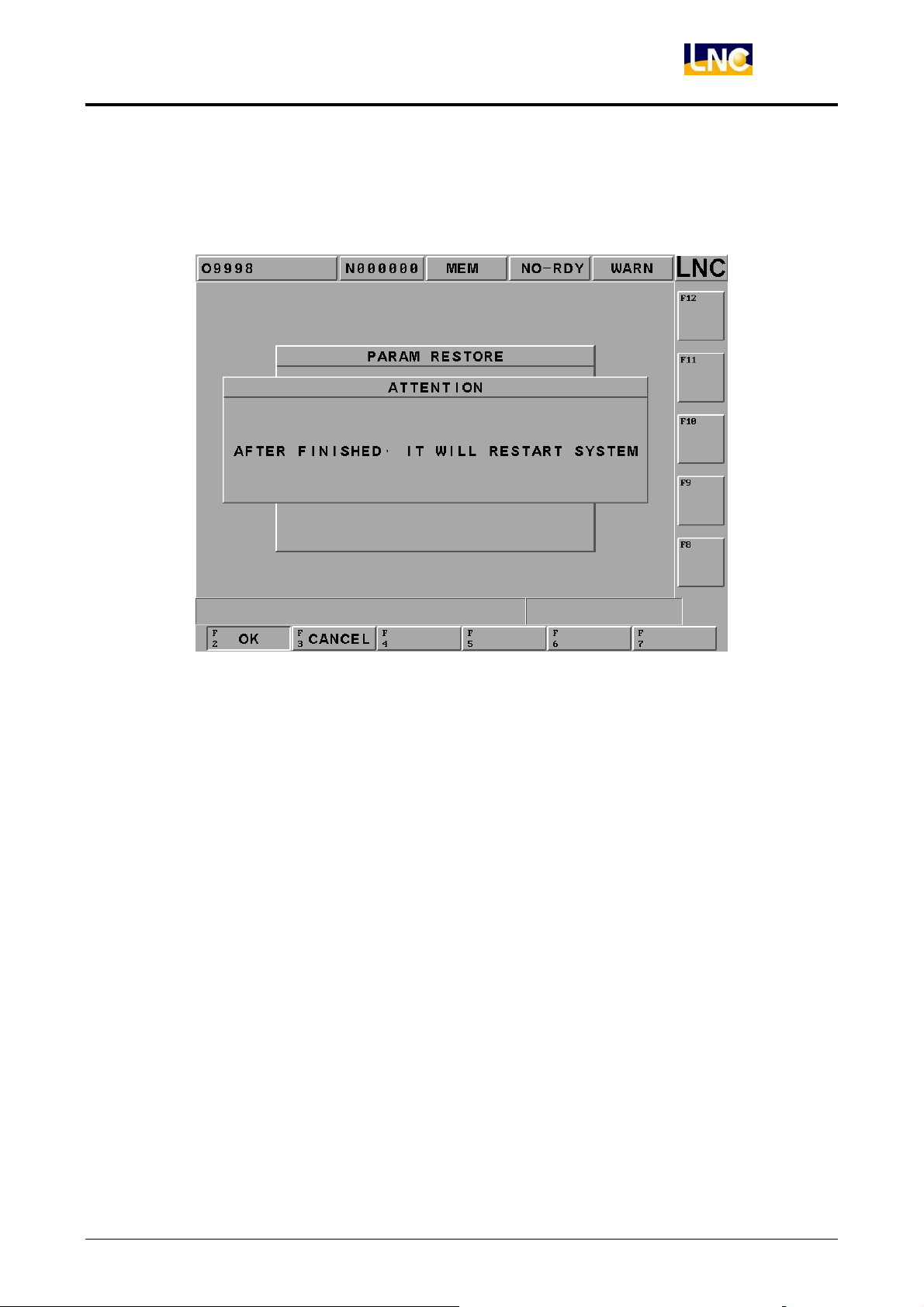
PARAM LEAD-IN
By choosing this function, a window dialog box will occur to remind users that needs to
reboot program
Figure 2.10-15 Reminding Users to Reboot after Key-in Parameter
If executing this function. Selecting the “renew parameter” item from the popup dialog box
after pressing confirm button. A dialog box of key-in parameter renew source path occurs
after pressing confirm button.
LNC Technology Co., Ltd. 89
Page 95
LNC-M650
CNC Operation
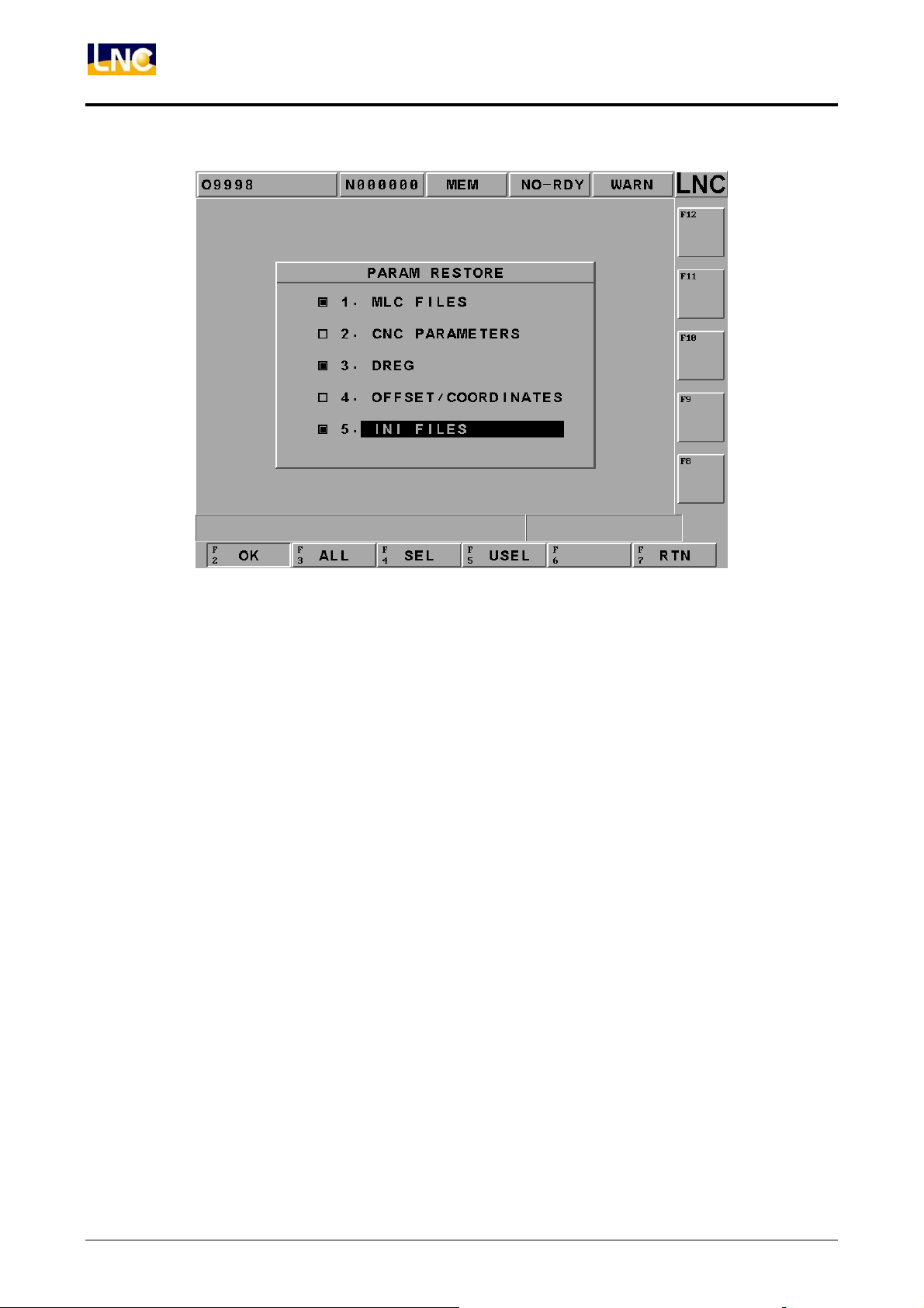
Figure 2.10-16 Screen of Choosing Key-in Parameter
Key-in or select the source path and file name after pressing confirm button to key-in
parameter file.
90
LNC Technology Co., Ltd.
Page 96
Text Font Installation
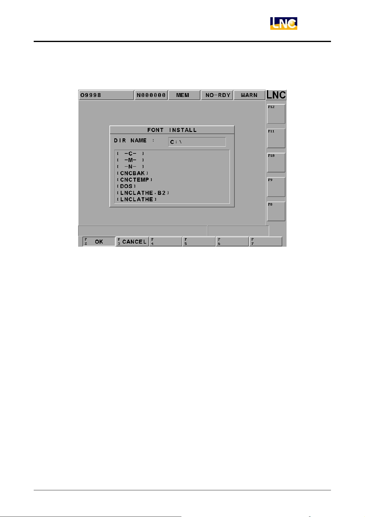
After user selects a designated text font source, please pressing【OK】.
LNC-M650
CNC Operation
Figure 2.10-17 Text Font Installation Source Page
LNC Technology Co., Ltd. 91
Page 97
LNC-M650
CNC Operation
2.10.7 CIRCUL
Figure 2.10-18 CIRCUL Screen
【Panel】
Able to choose any one of XY, YZ, ZX panes as the circular pane
from the popup menu after pressing <input>.
【CW/CCW】
Able to choose CW (G02) or CCW (G03) as the cycling motion
from the popup menu after pressing <input>.
【Sample Period】
Setting the sample interval time (ms) for estimation error.
【Center Point XYZ】 Absolute coordinates(X、Y、Z) of the entered center point.
【Radius】 Setting radius of circular(mm).
【Feedrate】 Setting feedrate of circular(mm/min).
【Sample Point #s】
Total numbers of the sample estimation: Sample point numbers=
(2*PI*circular radius*60*1000)/( feedrate * sample interval).
Note:PI= 3.1415926
【Average Error】
Display average error value.
Average error =total/sample point numbers
【Standard Error】
The difference between the data information and the balance
number.
【Max Error】
【Min Error】
The largest circular error value.
The smallest circular error value.
【Ratio】 Display the circular error’s zoom-in ratio(N / 1),N is the ratio.
Note: the canned cycle error is the distance between each
simple point and the center point and also the different value
between each simple point and cycle radius.
【Ratio +/-】
To set the error zoom-in ratio of the sub-function operation
92
LNC Technology Co., Ltd.
Page 98

LNC-M650
CNC Operation
button.
Pressing this key, this button will be sagged and 【Ratio -】will
occur. Pressing the key again, this button will be raising and
【Ratio +】will occur.
【1】 When the upper key displays 【Ratio +】, the ratio will increase
by 1 when pressing this button.
When the upper button display 【Ratio -】, the ratio will decrease
by 1 when pressing this button.
【10】 when the upper button displays 【Ratio +】, the ratio will increase
by 10 when pressing this button.
When the upper button display 【Ratio -】, the ratio will decrease
by 10 when pressing this button.
【100】 when the upper button displays 【Ratio +】, the ratio will increase
by 100 when pressing this button.
When the upper button display 【Ratio -】, the ratio will decrease
by 100 when pressing this button.
【Starting】
After canned cycle parameter setting is completed, pressing this
button in order to indicate the setting is completed. Wait until the
users press CYCLE START button in order to start the canned
cycle motion. Pressing this button again, the key will raise, which
means the canned cycle motion is canceled.
LNC Technology Co., Ltd. 93
Page 99
LNC-M650
CNC Operation
2.11 SOFTPL
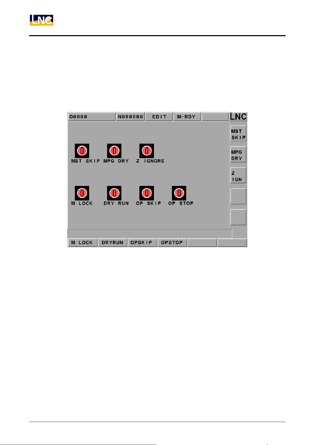
Press <SOFTPL> to enter into the diagrams display screen. There are 7 function selection
switches which are corresponding to 8 function buttons on the screen and they are【MST
SKIP】, 【MPG DRY】, 【Z IGNORE】, 【M LO CK】, 【DRY RUN】, 【OP SKIP】, and
【OP STOP】.
Figure 2.11-1 Soft Panel Function Screen
Using these corresponding function switches separately. The function picture changes
from red to green on the screen, which means the function is enabled. Turning it back
again to disable the function.
94
LNC Technology Co., Ltd.
Page 100
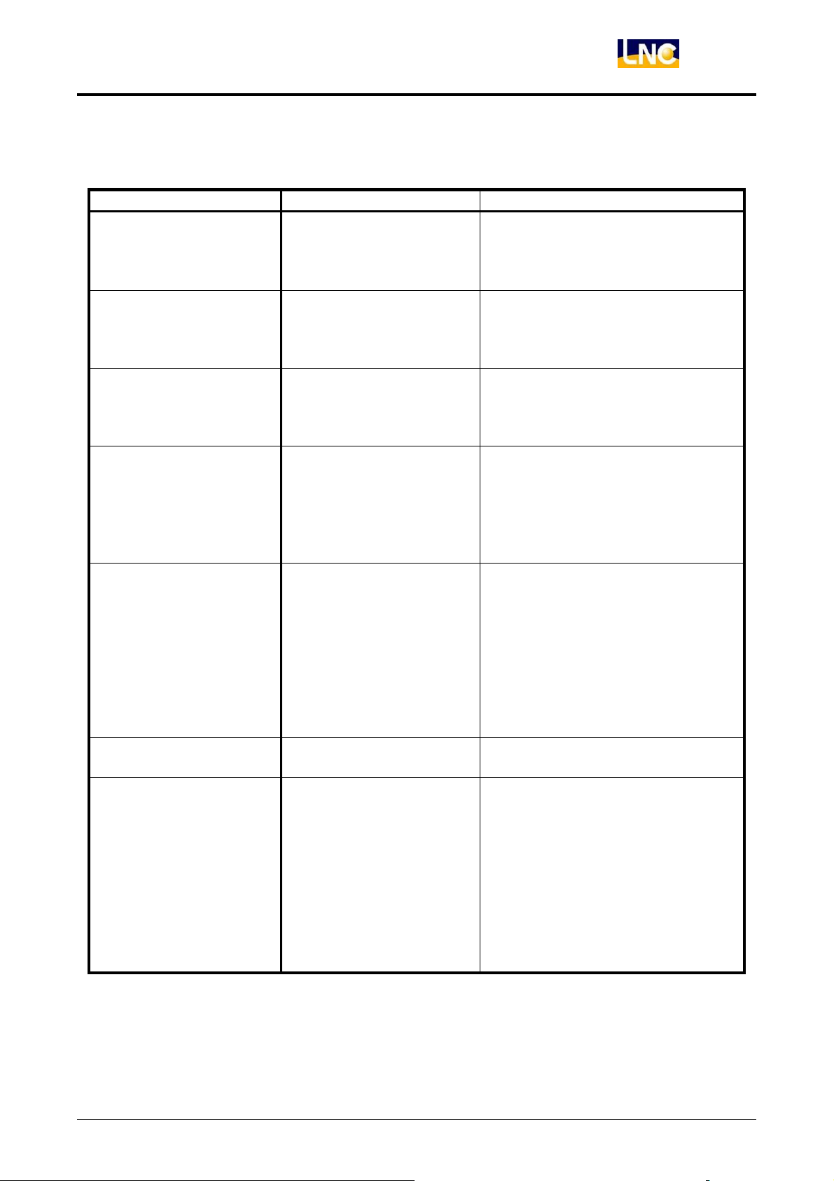
The Below Table Describes Each Soft Panel Function Selection Switches:
Function Switches ON OFF
Hand Wheel Dry
Run
Hand wheel can modify
the program coordinate,
but the servo axis will not
move actually.
Hand wheel can modify the
program coordinate and let the
servo axis moves according to it.
Automatic executing
Auto-OFF
power disconnecting and
exit motions after finish
Auto-OFF.
program executing.
Program begins with ”/”
Optional Skip
symbol will be skipped
and not
Single block that begins with ”/”
symbol will be executed normally.
be executed.
The program will stop
Optional Stop
when the program
executes up to M01. If
want to continue
executing, users need to
Controller will ignore M01 and
execute
the next single block directly.
press ”CYCLE START”.
While executing the
program,
the servo feed is
Dry Run
according to
the dry run speed
parameter,
The designated speed of the servo
feed program.
not according to the
assigned speed of the
program.
MST Ignore
Ignore M, S, T codes
commanding
Consider M, S, T codes
commanding
The controller will
continue executing
program while the
Machine Lock
program is executing.
But, the moving
command of the servo
axis will NOT be
The moving command of the servo
axis will be outputted with the
program while the program is
executing.
outputted. So actually, the
servo axis is completed
stop (no movement).
LNC-M650
CNC Operation
LNC Technology Co., Ltd. 95
 Loading...