

Page 1
LNC-T520i
O
O
p
p
err
e
att
a
orr''
o
Leading Numerical Controller
s
s
M
M
a
n
n
u
u
a
2007/10 Ver:V04.00.000
all
a
LNC Technology Co., Ltd.
LNC Technology Co., Ltd. 1
Page 2

Page 3

LNC T520i
Table of Content
Table of Content
1 GENERAL ............................................................................................... 1
1.1 HARDWARE SPECIFICATION ................................................................................. 2
1.2 SOFTWARE SPECIFICATION.................................................................................. 3
1.3 SYSTEM SETTING UNIT ....................................................................................... 4
1.4 G CODE TABLE................................................................................................... 5
2 CNC OPERATION................................................................................... 7
2.1 OPERATION INSTALLATION TYPE........................................................................... 7
2.2 OPERATION INSTALLATION INSTRUCTION............................................................... 8
2.3 SCREEN AND FUNCTION DESCRIPTION ............................................................... 13
2.3.1 Display Screen Layout....................................................................... 13
2.3.2 Function Groups................................................................................ 14
2.3.3 ABS (Absolute Coordinate) ............................................................... 22
2.3.4 REL (Relative Coordinate)................................................................. 23
2.3.5 MAC (Machine Coordinate) ............................................................... 24
2.3.6 Exit System Screen ........................................................................... 25
2.4 PROG FUNCTION ............................................................................................ 26
2.4.1 FGPROG (Foregoing Program)......................................................... 27
2.4.2 BGPROG (Background Program) ..................................................... 29
2.4.3 PROCHK (Program Checking) .......................................................... 30
2.4.4 DIR MNG (File Management)............................................................ 32
2.4.5 RS232 ............................................................................................... 41
2.4.6 DNC Function.................................................................................... 46
2.5 OFFSET......................................................................................................... 47
2.5.1 WEAR (Wear OFFSET)..................................................................... 47
2.5.2 GEOM (Geometry OFFSET) ............................................................. 50
2.5.3 W. SHIFT (Work Coordinate Shift)..................................................... 51
2.5.4 MACRO ............................................................................................. 52
2.5.5 WORK (Coordinate Setting) .............................................................. 54
2.6 LATHE EASY-CAM .......................................................................................... 57
2.6.1 Function Description.......................................................................... 57
2.6.2 Operation Procedure of How to Produce Working Path Program...... 57
2.6.3 Operation Screen and Function Key Instruction ................................ 59
Pou Yuen Technology Corp. I
Page 4

LNC T520i
Table of Content
2.7 GRAPH(GRAPH) ...................................................................................... 85
2.7.1 Function Introduction ......................................................................... 85
2.7.2 SIMU ................................................................................................. 85
2.7.3 Window Definition.............................................................................. 88
2.8 DGNOS.......................................................................................................... 90
2.8.1 ALARM .............................................................................................. 90
2.8.2 System Upgrade................................................................................ 93
2.8.3 IOCSA ............................................................................................. 100
2.8.4 MLC2............................................................................................... 102
2.8.5 SYSTEM.......................................................................................... 107
2.9 SOFTPL........................................................................................................110
2.10 PARAM .........................................................................................................112
2.10.1 NC. SYS (System Parameter) ..........................................................112
2.10.2 Users Parameter ..............................................................................116
2.10.3 Authorization ....................................................................................117
2.11 RESET......................................................................................................... 122
3 OP PANEL OPERATION..................................................................... 123
3.1 POWER SWITCH (ON/OFF)............................................................................. 124
3.2 EMG-STOP KEY........................................................................................... 125
3.3 CYCLE START............................................................................................. 126
3.4 FEED
3.5 LED
3.6 MODE SELECT ........................................................................................... 128
3.7 AXIS
3.8 SPINDLE
3.9 CHUCK .......................................................................................................... 131
3.10 OT RELEASE............................................................................................... 132
3.11 COOLANT SUPPLY ..................................................................................... 133
HOLD................................................................................................. 127
SIGNAL ................................................................................................ 127
SELECTION........................................................................................ 129
ROTATION................................................................................... 130
3.12 TOOL MAGAZINE........................................................................................ 133
3.13 WORKING LIGHT AND TAIL-BASE BUTTON ......................................................... 134
II Pou Yuen Technology Corp.
Page 5

LNC T520i
General
1 General
LNC-T520i is a PC-based controller for CNC lathe machines. It is a highly technology
product that is developed by the POU YUEN TECHNOLOGY Ltd. through years of
dedicating research and development, involving massive manpower and resources.
LNC-520i serial controller is featured in high–speed, high–precision, and high–efficiency.
In the following chapters, operating instruction of LNC-T520i controller will be introduced.
LNC Technology Co., Ltd.
1
Page 6
A
LNC T520i
General
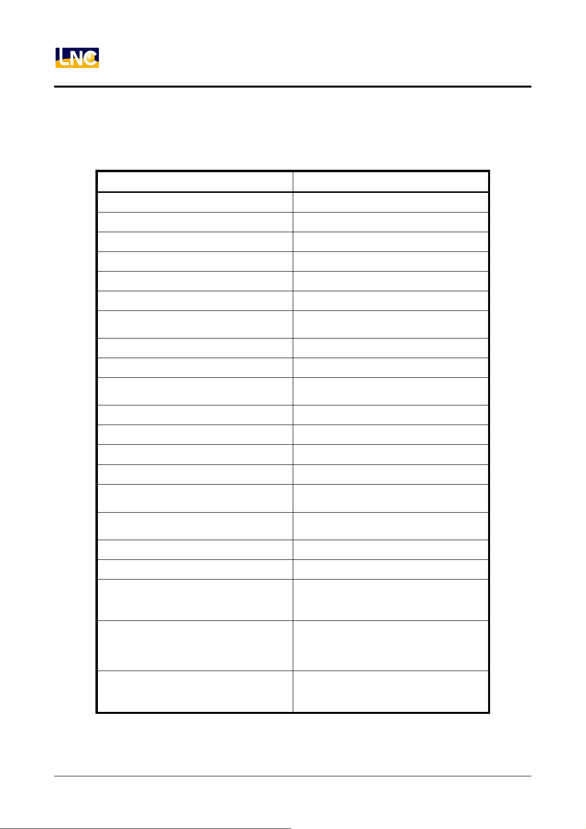
1.1 Hardware Specification
LNC-520i Specification
Display device 8.4”Color TFT LCD
CPU GX1-300
DRAM RAM 64M bytes or above
Double CF Card Each 32M bytes or above
Floppy Diskette Panel and Power
PC(CPU BOARD)
Spindle System
Standard FDD;5V/12V
Industrial PC Board
Support Pulse Control Plus DA
Output
Remote I/O 128 Input / 128 Output
USER I/O 20 Input / 16 Output
Servo System
Provide Position/Speed Circuit
Control
DNC RS232 19200 Baud Rate
Operation Panel Standard Milling OP Panel
Hand Wheel Panel 3 in 1 MPG
Controllable Axis 3 Axes
Linear Interpolation Simultaneous
Axis
rch Interpolation Simultaneous
Axis
3 Axes
3 Axes
MPG Controllable Axis 3 Axes
Spindle Axis 1 Axis
0.001 mm
Min. Input Unit
0.0001 inch
0.001 deg
0.001 mm
Min. Commanding Unit
0.0001 inch
0.001 deg
Power Supply
<<Must use double power
supplies>>
(First Power Set) 12V(2A)、5V(6A)
(Second Power Set) 24V(2A)
2 LNC Technology Co., Ltd.
Page 7
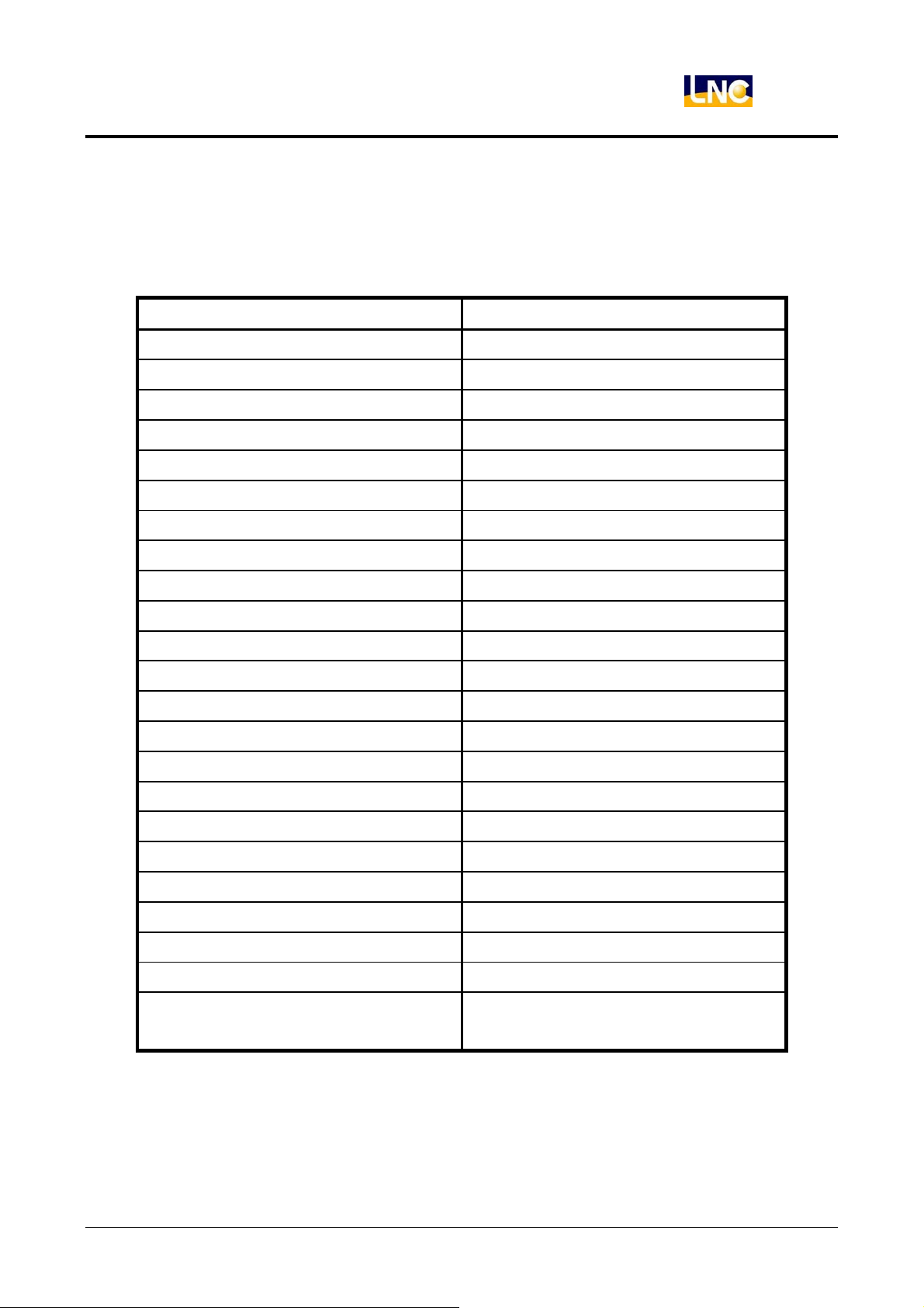
1.2 Software Specification
LNC-T520i Specification
File Format DOS FAT
Program Specification Normal G, M Code Program
Background Editing Function
Macro Program Function
Module Type EDIT
MEM
LNC T520i
General
MDI
JOG
MPG
RAPID
HOME
Screen Group Function POS
PROG
OFFSET
CAM
GRAPH
DGNOS
SOFTPL
PARAM
MLC(Machine Logic Controller)
I/O/C/S/A BIT
Timer/Counter/Register
Ladder Program Display
Language Tradition/Simplify Chinese and
LNC Technology Co., Ltd.
English
3
Page 8
LNC T520i
General
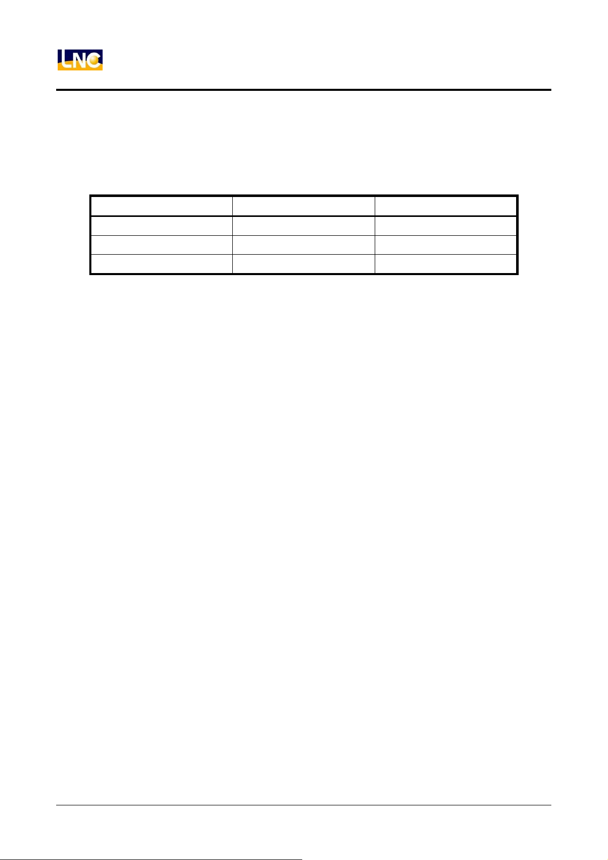
1.3 System Setting Unit
Min. Input Unit Min. Commanding Unit Max. Travel Setting
0.001 mm 0.001 mm 99999.999 mm
0.0001 inch 0.0001 inch 9999.9999 inch
0.001 deg 0.001 deg 99999.999 deg
4 LNC Technology Co., Ltd.
Page 9
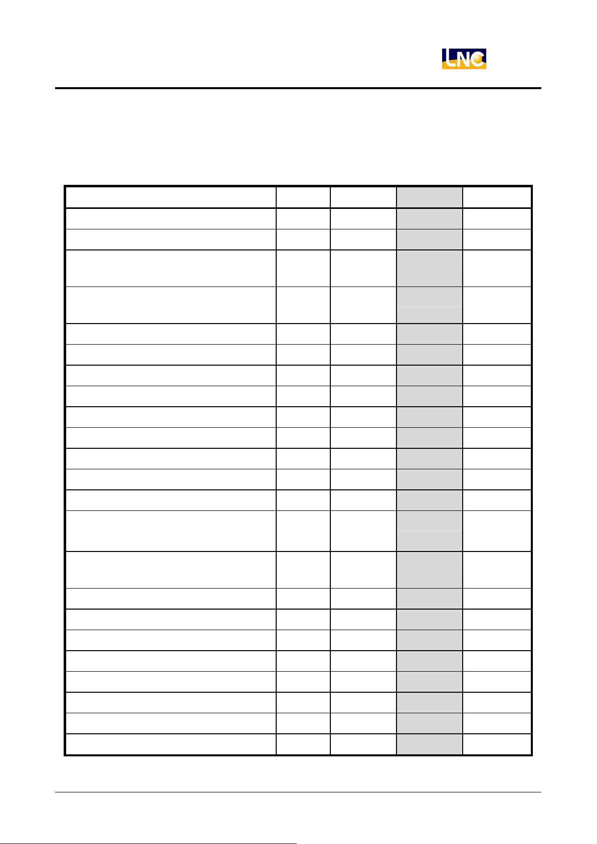
1.4 G Code Table
Function Description Group TYPE A TYPE B TYPE C
LNC T520i
General
Positioning (Rapid Traverse)
Linear Interpolation (Cutting Feed)
Circular/Helical Interpolation
01 G00 G00 G00
01 G01 G01 G01
01 G02 G02 G02
Clockwise
Circular/Helical Interpolation Counter
01 G03
G03 G03
Clockwise
Dwell
Exact Stop
Programmable Data Input
Input in Inch
Input in mm
00 G04 G04 G04
00 G09 G09 G09
00 G10 G10 G10
06 G20 G20 G70
06 G21 G21 G71
Tool Travel Limit ON 09 G22 G22 G22
Tool Travel Limit OFF 09 G23 G23 G23
Return to Reference Position
1st Reference Position Return
00 G27 G27 G27
00 G28,G29
G28,G29 G28,G29
2nd, 3rd, and 4th Reference Position
00 G30 G30 G30
Return
Tool Noise Radius Compensation
07 G40
G40 G40
Cancel
Tool Noise Radius Left
Tool Noise Radius Right
07 G41 G41 G41
07 G42 G42 G42
Absolute Commanding 03 - G90 G90
Incremental Commanding 03 - G91 G91
Coordinate System Setting 00 G50 G92 G92
Feed Per Minute Setting mm/min.
Feed Per Minute Setting mm/rev.
Constant Surface Speed Control
LNC Technology Co., Ltd.
5
05 G98 G94 G94
05 G99 G95 G95
02 G96 G96 G96
Page 10
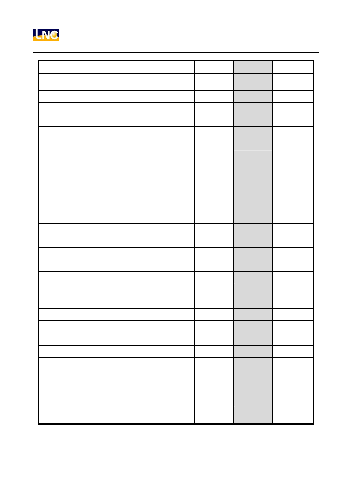
LNC T520i
General
Function Description Group TYPE A TYPE B TYPE C
Constant Surface Speed Control
02 G97 G97 G97
Cancel
Thread Cutting 01 G32 G33 G33
Composite Constant Fine Cutting
00 G70 G70 G72
Cycle
Composite Constant Horizontal
00 G71 G71 G73
Rough Cutting Cycle
Composite Constant Side Rough
00 G72 G72 G74
Cutting Cycle
Composite Constant Forge-Embryo
00 G73 G73 G75
Rough Cutting Cycle
Composite Constant Side Peck
00 G74 G74 G76
Cutting Cycle
Composite Constant Horizontal Peck
00 G75 G75 G77
Cutting Cycle
Composite Constant Thread Cutting
00 G76 G76 G78
Cycle
Single Axis Constant Cutting Cycle 01 G90 G77 G20
Single Tread Constant Cutting Cycle 01 G92 G78 G21
Single Constant Cutting Cycle 01 G94 G79 G24
Constant Cycle for Drilling 10 G80 ~ G89 G80 ~ G89 G80 ~ G89
MACRO Calling
MACRO Modal Calling
MACRO Modal Calling Cancel
Returning to Initial Level
Returning to R Point Level
Exact Stop Mode
Normal Cutting Mode
Working Coordinate Systems
00 G65
12 G66 G66 G66
12 G67 G67 G67
11 - G98 G98
11 -
15 G61 G61 G61
15 G64 G64 G64
14 G54 ~G59 G54 ~ G59 G54 ~ G59
G65 G65
G99 G99
Selection
Note:TYPE A, B or C are decided by Parameter 153, the default value is TYPE B.
6 LNC Technology Co., Ltd.
Page 11
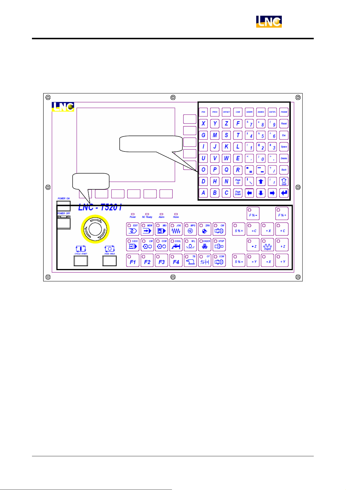
2 CNC Operation
LNC T520i
CNC Operation
MDI
OP Panel
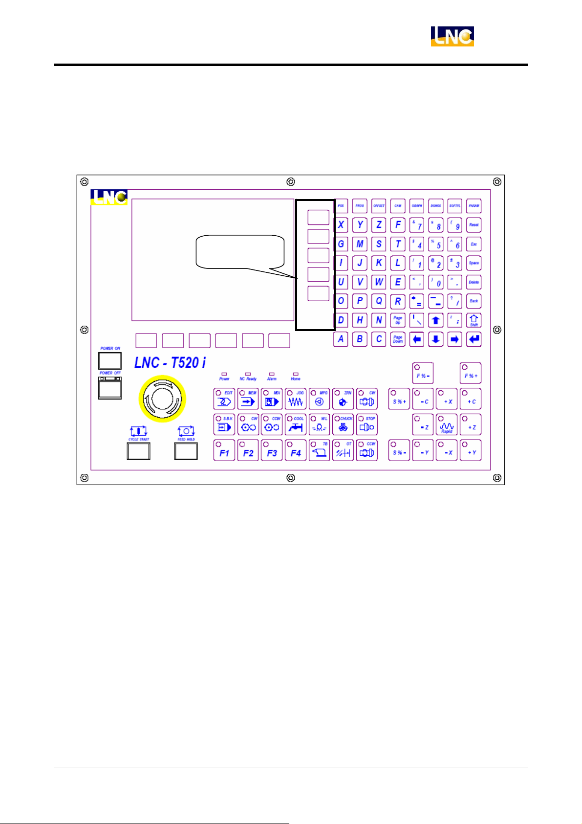
2.1 Operation Installation Type
Operation panel is divided into Manual Data Input (MDI) section and Operation (OP)
section. MDI is to let users to edit word by word, to modify program and to set value. The
OP panel is to finish working needs in order to meet user’s demand.
LNC Technology Co., Ltd.
7
Page 12
LNC T520i
CNC Operation
2.2 Operation Installation Instruction
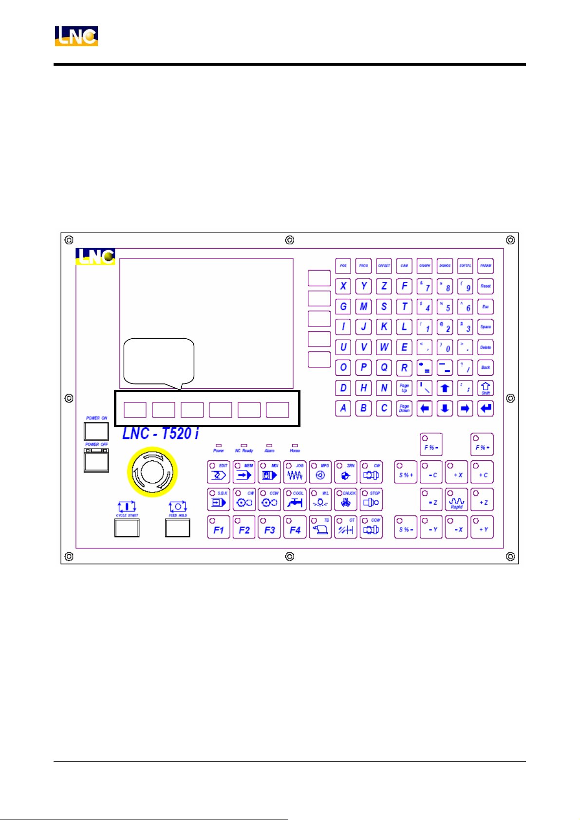
Function keys on the MDI can be divided into 4 categories:
(1) Main Function Key:
On the LCD Panel, there are 6 keys for users to select the correspondent main
functions.
Main
Function
8 LNC Technology Co., Ltd.
Page 13
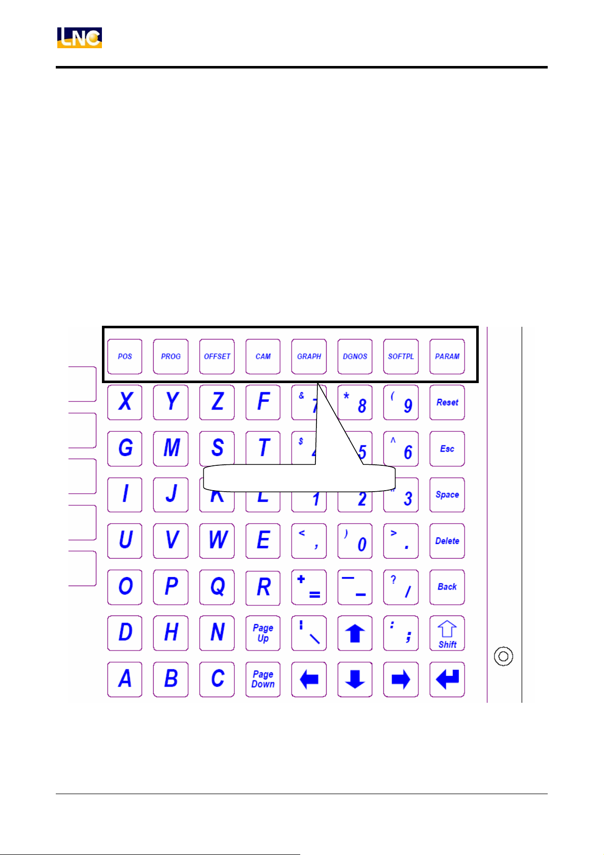
(2) Sub Function Keys:
After selecting the main function key, the sub function key will be displayed on the
right side of the screen. Users can press the corresponding sub function key for the
sub function to be occurred on the screen.
LNC T520i
CNC Operation
Sub Function
Keys
LNC Technology Co., Ltd.
9
Page 14
LNC T520i
CNC Operation
(3) Function Group Selection Key:
Eight Functions are POS, PROG, OFFSET, CAM, GRAPH, DGNOS, SOFTPL and
PARAM.
1. <POS> :Displaying all coordinate group on the screen
2. <PROG> :Displaying all program data on the screen
3. <OFFSET> :Setting tool OFFSET
4. <CAM> :Editing work program by using diagrams
5. <GRAPH> :Drawing tool path
6. <DGNOS> :Displaying instant message on the DGNOS screen
7. <SOFTPL> :Selecting switch on the soft panel
8. <PARAM> :Displaying parameter screen
Function Group Selection Keys
10 LNC Technology Co., Ltd.
Page 15

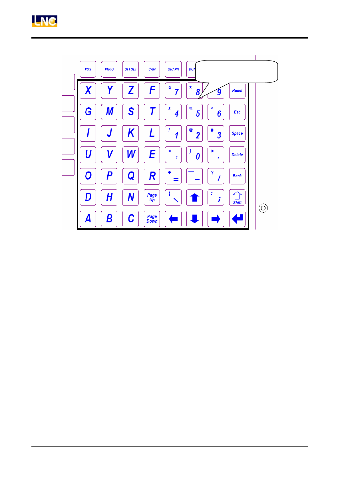
(4) Character and Symbol and Editing Keys:
This characters, symbols and numbers are for program editing and data inputting.
Some symbols are diminished at the lower right side of some buttons. If users want
to use these special characters, please pressing Shift + the symbol key at the same
time. Editing key is for users to modify program, to set information and to change
page.
1. <Reset> :System Reset
2. <Esc> :Canceling all communication boxes
3. <Space> :Entering a space character
4. <Delete> :Deleting character key
LNC T520i
CNC Operation
5. <Back> :Canceling previous character
6. <Shift> :Entering special symbols
7. < > :Entering key
8. <Page Up> :Turning to previous page
9. <Page Down> :Turning to next page
10. <→> :Moving cursor right
11. <←> :Moving cursor left
12. <↑> :Moving cursor down
13. <↓> :Moving cursor up
LNC Technology Co., Ltd.
11
Page 16
LNC T520i
CNC Operation
Character and Symbol and
Editing Keys
12 LNC Technology Co., Ltd.
Page 17
LNC T520i
CNC Operation
2.3 Screen and Function Description
This controller can be divided into 8 function groups such as POS, PROG, OFFSET, CAM,
GRAPH, DGNOS, SOFTPL and PARAM. This manual uses 【 】 to indicate the
function keys at the screen bottom and at the right side of a screen. Also, using < > to
indicate buttons on the MDO panel.
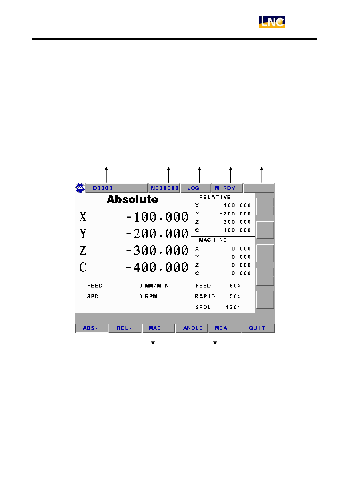
2.3.1 Display Screen Layout
1 2 3 4 5
1:present designate file name
2:present single block that is executed by controller
3:CNC mode signal
4:machine condition signal
5:wrong alarm/warning message
6:simply message hint area
7:entry area
LNC Technology Co., Ltd.
7 6
13
Page 18
LNC T520i
CNC Operation
2.3.2 Function Groups
POS (Position Coordinate Function Group)
POS
ABS ABS
MPG
REL
MAC
PARAM
Exit
X CLR.
All CLR.
Time CLR.
PART CLR.
Figure 2.3-1 Position Coordinate Layout
Z CLR.
INTCNT
MAXCNT
14 LNC Technology Co., Ltd.
Page 19
PROG (Program Editing Function Key)
PROG
LNC T520i
CNC Operation
FGPROG
BGPROG
PROCHK
GOTO
LDEL
MARK UNMARK
COPY CUT
PASTE
MDI CUR
DIRMNG
COMM.
LNC Technology Co., Ltd.
FILE
COPY
COPY A>C
REN
COMM
Figure 2.3-2 Program Editing Layout
15
SETT
Page 20
LNC T520i
CNC Operation
OFFSET Function Key
OFFSET
WEAR
GEOM
W.SHIFT
MACRO
WORK
ABS
NORUNT
SET X
INC
MINUNT
SET Z
SET ALL
Figure 2.3-3 OFFSET Layout
16 LNC Technology Co., Ltd.
Page 21

CAM Screen Function Keys
LNC T520i
CNC Operation
CAM
PRJ.MNG
SAVE
CONVER
CLOSE
PROCAD
PROCINS
PROCCPY
PROCDEL
LNC Technology Co., Ltd.
Figure 2.3-4 CAM Layout
17
Page 22

LNC T520i
CNC Operation
Preview Screen Function Keys
GRAPH
GRAPH
Win. Def.
Figure 2.3-5 Preview Screen Layout
18 LNC Technology Co., Ltd.
Page 23
DGNOS Screen Function Keys
DGNOS
LNC T520i
CNC Operation
ALARM
SYSUPD
ALARM WARN
HISMSG
LOGHST
IOCSA I BIT O BIT
C BIT
S BIT
A BIT
MLC2
LAD
REG
CNT
DRG
SYSTEM
LNC Technology Co., Ltd.
TMR
GBL H.D
Figure 2.3-6 DGNOS Layout
19
Page 24
LNC T520i
CNC Operation
SOFTPL Function Keys
SOFTPL
M LOCK
DRY RUN
OP SKIP
OP STOP
MST SKIP
MPG DRY
Z IGN
Figure 2.3-7 SOFTPL Layout
20 LNC Technology Co., Ltd.
Page 25
PARAM Function Keys
PARAM
LNC T520i
CNC Operation
NC.SYS
USROPT
SRVO
HOME
OPER
SPDL
MAC *
MPG *
COMP *
Auth. SET
CHK LOCK
Figure 2.3-8 PARAM Layout
Note: * means for machine makers use only.
LNC Technology Co., Ltd.
21
PWD.
Page 26
LNC T520i
CNC Operation
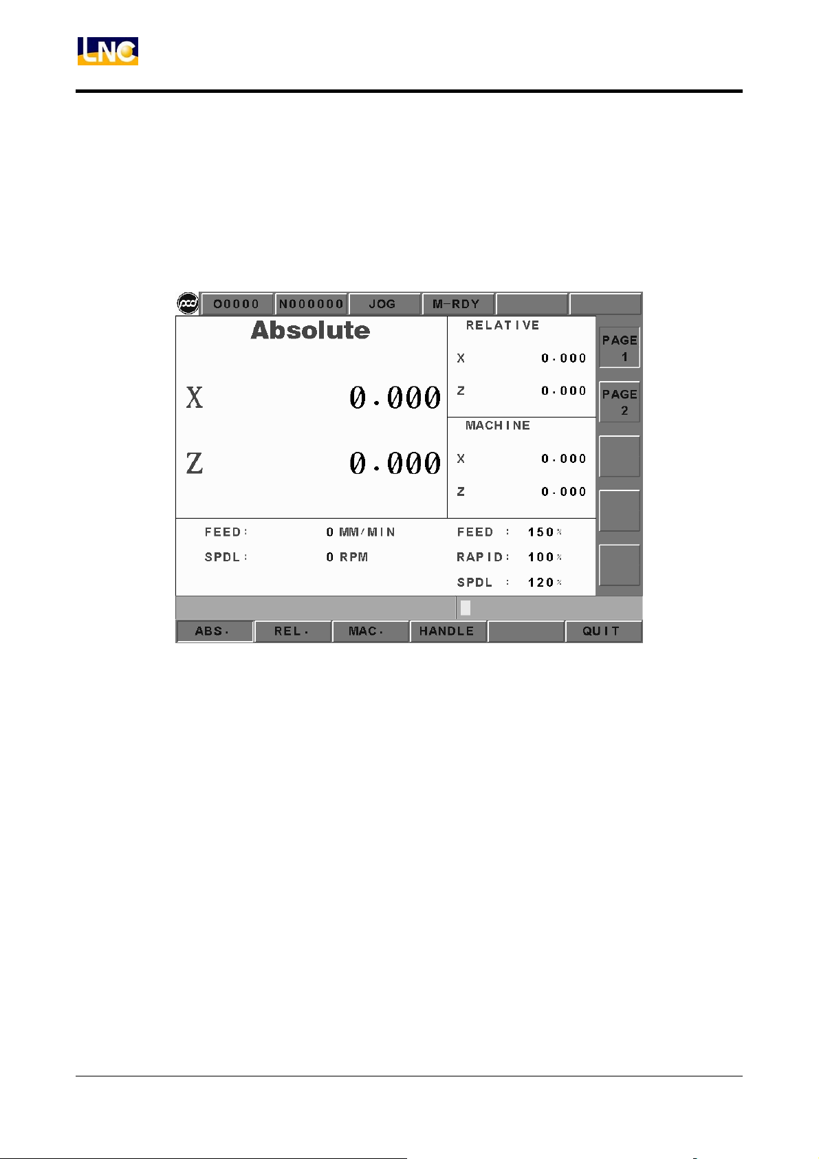
2.3.3 ABS (Absolute Coordinate)
Pressing 【ABS.】to enter into absolute coordinate screen. Beside the absolute coordinate
screen are sub-screens for【REL.】, and【MAC.】.
Figure 2.3-9 Absolute Coordinate Screen
Absolute coordinate is the program coordinate, which is [present value – tool offset =
program value]. This will display the present executing position of each axis minus each
axis offset.
22 LNC Technology Co., Ltd.
Page 27
LNC T520i
CNC Operation
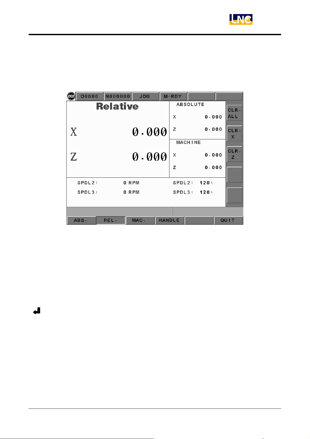
2.3.4 REL (Relative Coordinate)
Pressing 【 REL.】 to enter into the relative coordinate screen. Beside the relative
coordinate screen are sub-screens for【ABS.】and【MAC.】.
Figure 2.3-10 Relative Coordinate Screen
The relative coordinate system means the distance between the present position and any
point that is decided by users. So users can set the relative coordinate value to zero
anytime, or enter any non-zero value directly.
If want to reset the coordinate value and to let X coordinate to 100.00, Y coordinate to
200.000 and Z coordinate to 300.000, only need to set X100, Y200, Z300. Then, pressing
<> to reset the coordinate value immediately.
If want to set the 3 axes relative coordinate values to zero separately or at the same time,
only need to press the corresponding sub-function buttons 【CLR. X】, 【CLR. Y】, 【CLR.
Z】, and【CLR. All】to execute the corresponding clean.
LNC Technology Co., Ltd.
23
Page 28
LNC T520i
CNC Operation
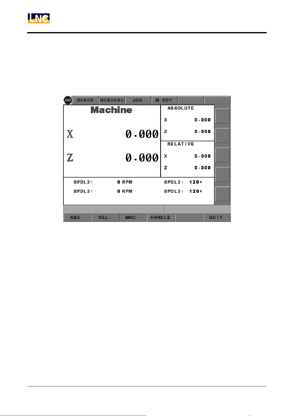
2.3.5 MAC (Machine Coordinate)
Pressing 【 MAC.】 to enter into the relative coordinate screen. Beside the machine
coordinate screen are sub-screens for【ABS.】and【REL.】.
Figure 2.3-11 Machine Coordinate Screen
Machine coordinate is the distance between the present position corresponding to the
reference point. Each machine has its own reference point. For safety concern, please
looking for the reference point whenever reboot machine before executing work.
24 LNC Technology Co., Ltd.
Page 29
LNC T520i
CNC Operation
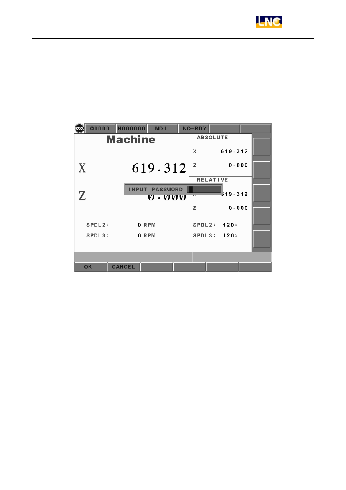
2.3.6 Exit System Screen
Pressing【EXIT】function button to enter into code entry windows and key-in correct codes.
Pressing【OK】button to exit CNC system and returning back to DOS system. Pressing
【CANCEL】button to return back to program and to continue executing.
Figure 2.3-12 Exit System Screen
LNC Technology Co., Ltd.
25
Page 30
LNC T520i
CNC Operation
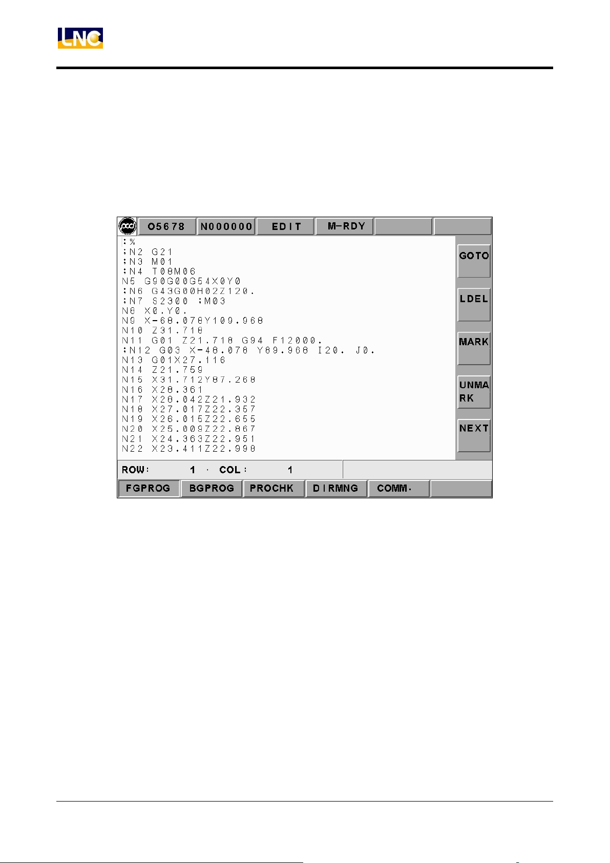
2.4 PROG Function
Pressing <PROG> is to enter into program function group screen. This function group
provides part program editing, checking, file managing, and RS232 transmitting and other
related functions.
Figure 2.4-1 FGPROG Screen
26 LNC Technology Co., Ltd.
Page 31

LNC T520i
CNC Operation
2.4.1 FGPROG (Foregoing Program)
Under editing condition, pressing 【FGPROG】 to display the program content of the
current opened controller. At this time, use the sub-function button at the right side and the
entering rows at the bottom of the screen to do the program editing.
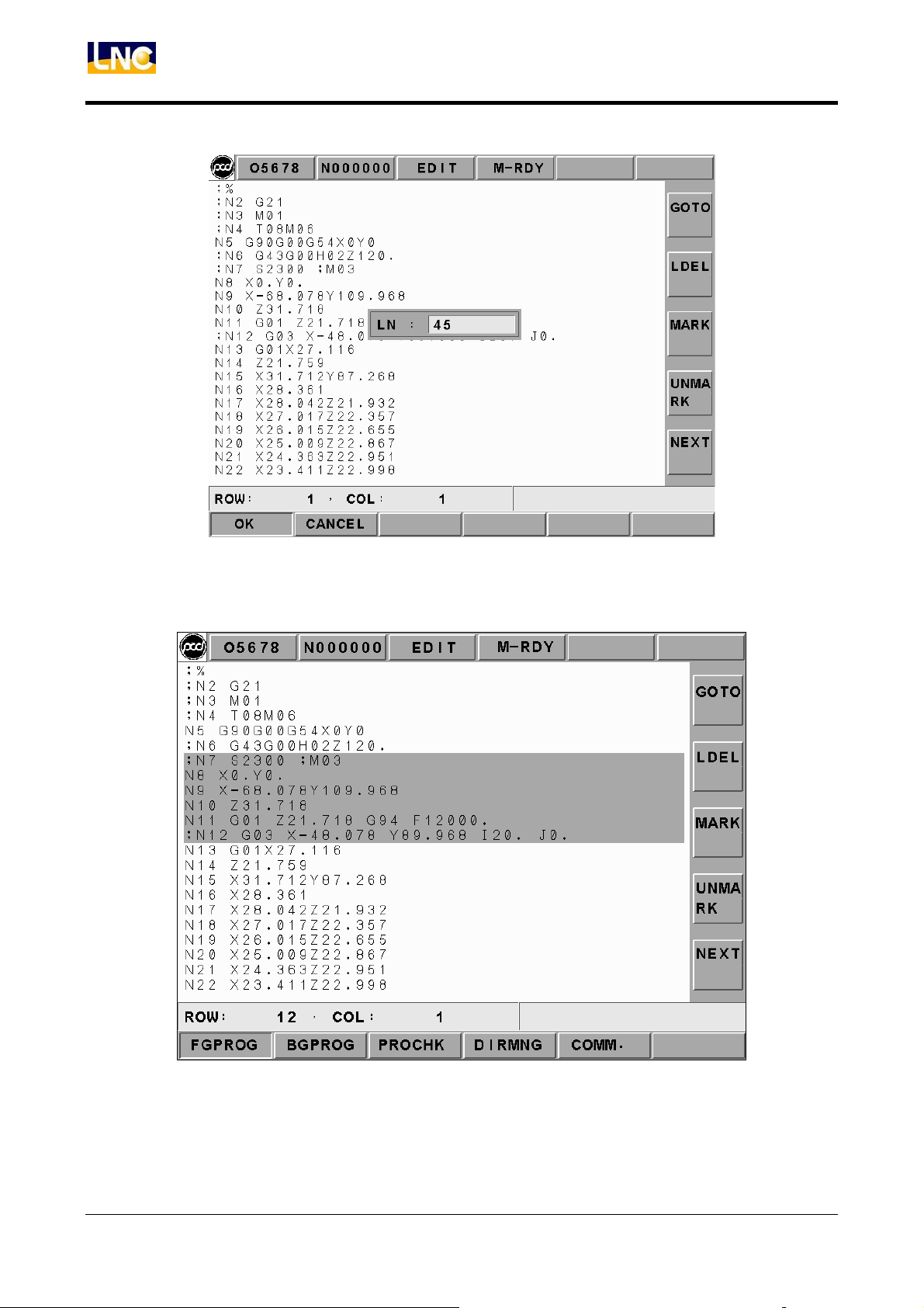
1. GOTO: Pressing【GOTO】function button at the right side to key-in “ROW’ number of
the program in the dialog box. Pressing【】to move the cursor to the assigned row
orientation (like Figure 2.5-2).
2. LDEL (Row Delete):Deleting a row of program codes at the cursor position.
3. MARK: Pressing【MARK】at the right side of the screen to move the cursor to the
wanted marking row’s starting/ending point. Moving the cursor to the starting/ending
position of the wanted marking row and pressing the【MARK】function key again to
mark the designated marking rows (like Figure 2.5-3).
4. UNMARK:Unmarking previous marking.
5. COPY:Copying the marked program in local range.
6. CUT:Cutting down the marked program in local range.
7. PASTE: Pasting on the program codes that are copied or cut at previous time.
Note: Not able to execute program enabling in editing mode.
LNC Technology Co., Ltd.
27
Page 32
LNC T520i
CNC Operation
Figure 2.4-2 Screen of Row Position Entry Column
Figure 2.4-3 Screen of Row Position Entry Column
28 LNC Technology Co., Ltd.
Page 33
LNC T520i
CNC Operation
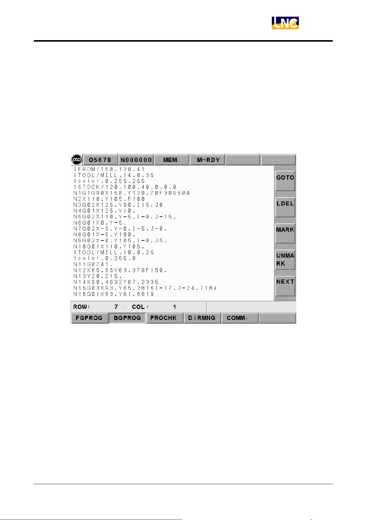
2.4.2 BGPROG (Background Program)
Pressing 【 BGPROG 】 to enter into background editing mode under auto mode.
Background editing allows users to edit another part program while executing one part
program in auto mode. Editing method and the environment of doing present program in
editing mode are totally the same.
LNC Technology Co., Ltd.
Figure 2.4-4 BGPROG Editing Mode
29
Page 34
LNC T520i
CNC Operation
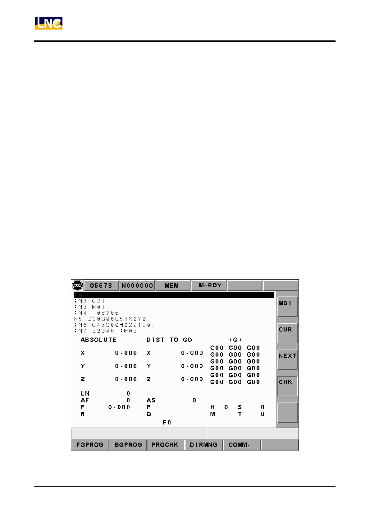
2.4.3 PROCHK (Program Checking)
Under auto mode, pressing【PROCHK】function buttons to enter into the auto program
checking screen as below figure. Sub-function buttons, at right side of the screen, provide
checking options.
【PROCHK】
To display data information of the present executing single block.
【NEXT】
To display data information of the next single block.
【CHK】
The upper half of the main screen will display program content and the currently
executing program will be highlighted. The bottom half has coordinate values,
M/S/G/T codes present value, actual speed display and etc.
Figure 2.4-5 【PROCHK】Screen
30 LNC Technology Co., Ltd.
Page 35
LNC T520i
CNC Operation
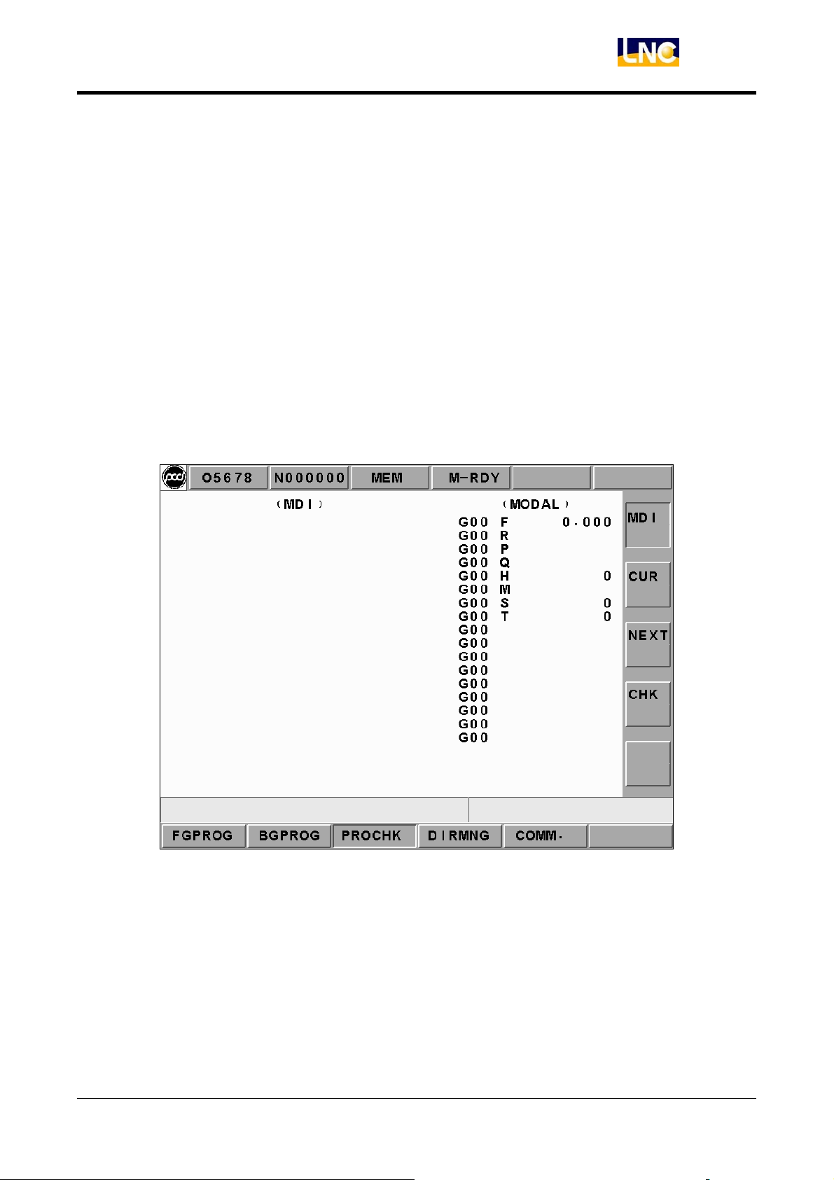
Pressing 【PROCHK】 function button under MDI mode to enter into the MDI screen as the
below figure. In this screen, users are able to execute a single block program. The
operation method is as the following steps:
1. To key-in a single motion command,
2. To press <INPUT> button and this command will occur at left half side of the
main screen,
3. To press (Cycle Start) button, and then the system will execute this command
immediately and the related information will occur.
It is more safe and time-efficiency when using this method to do testing.
LNC Technology Co., Ltd.
Figure 2.4-6 【PROCHK】Screen
31
Page 36
LNC T520i
CNC Operation
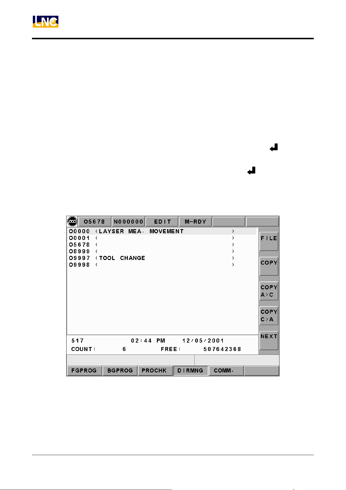
2.4.4 DIR MNG (File Management)
In file management screen, system provides the related file opening, copying, deleting,
renaming, and setting menu functions. A detailed description is as following.
【FILE】
1. Able to use direction key to choose the wanted open file after entering into the file
management screen. Also, users are able to open a file after pressing < >.
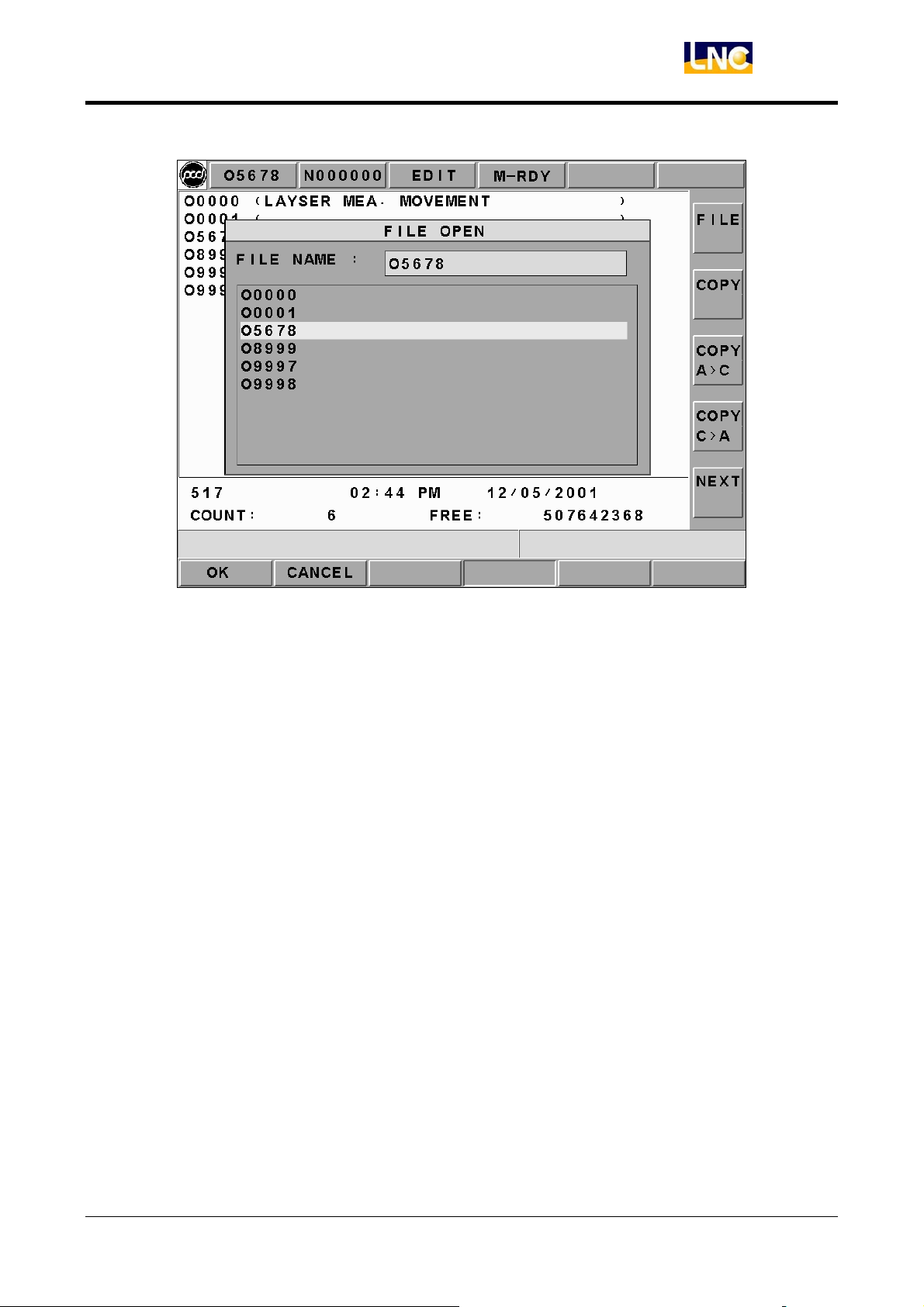
2. After pressing open file selection button, a dialog box will occur on the screen. Please
choose or key-in the wanted open file name and then pressing < > to open the file.
3. The opened file is a background program under auto mode. Automatically setting the
opened file to the present program under editing mode means NOT able to open the
file under other modes.
Figure 2.4-7 DIRMNG Screen
32 LNC Technology Co., Ltd.
Page 37
LNC T520i
CNC Operation
Figure 2.4-8 Screen of Pressing【FILE】Button
【COPY】
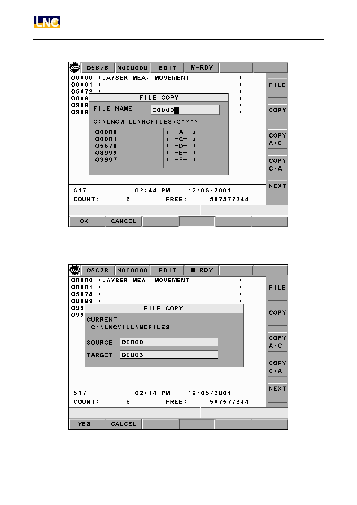
1. A dialog box of file copying will occur on the screen by pressing copy button. Users
are able to choose or key-in the file’s path or file name as the source file when copy
files. The screen after pressing copy function button is as Figure 2.4-9. After
completed entering and pressing confirm button, the screen of entering the destination
file is as figure 2.4-10.
2. Able to key-in the copied destination file name in the destination file column. If only
key-in file name, then the file path is the system default value.
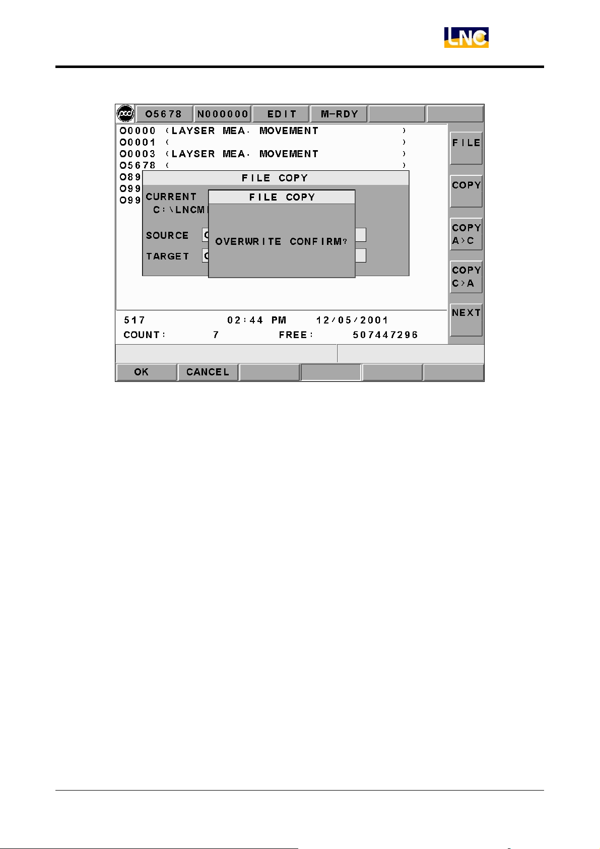
3. If the file is already existed, then the reminding windows will occur. Please confirm if
want to execute overwriting action. The screen is as Figure2.4-11.
4. If the program is copying, the message-reminding dialog box will occur “Copying….”
When complete, the message-reminding dialog box will occur “Copy Complete”.
LNC Technology Co., Ltd.
33
Page 38
LNC T520i
CNC Operation
Figure 2.4-9 Screen of Pressing【COPY】Function Button
Figure 2.4-10 Screen of Key-In Destination File Name
34 LNC Technology Co., Ltd.
Page 39
LNC T520i
CNC Operation
Figure 2.4-11 Screen When the Copied File is Already Existed
LNC Technology Co., Ltd.
35
Page 40
LNC T520i
CNC Operation
【REN】
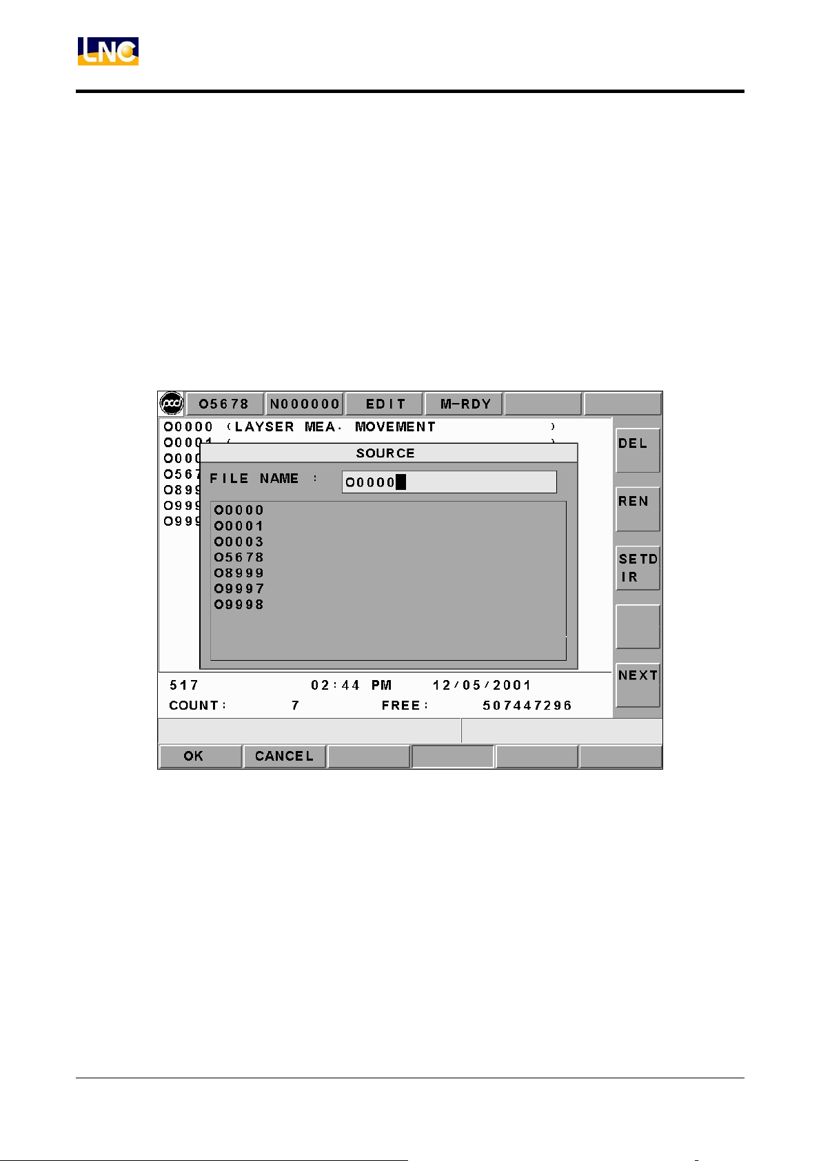
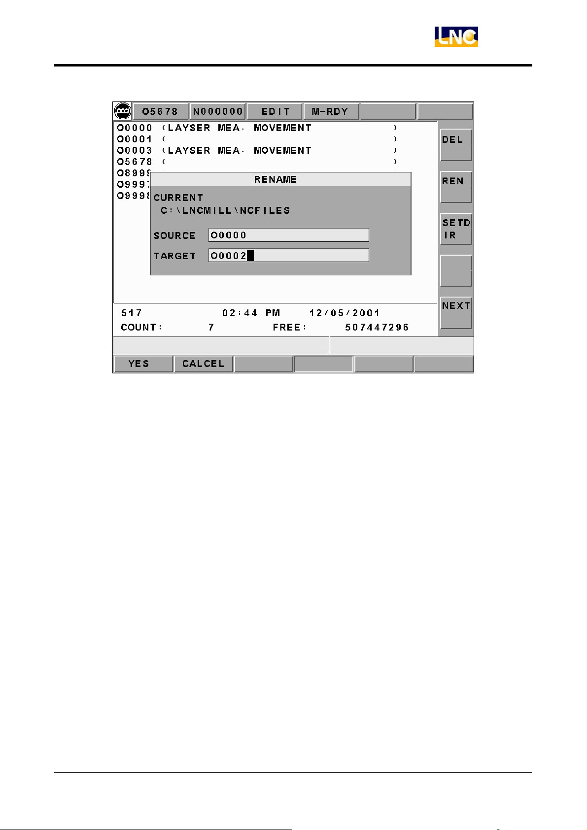
1. After pressing rename function button, a rename file source windows will occur on the
screen. Users are able to choose the wanted change’s file name. Pressing confirm
button to enter into the file rename windows.
2. To enter the destination file name in the rename windows and then to press confirm
button. After rename complete, users will be able to use program list to confirm.
Note: Please key-in “O0000” as a default file name into the source dialog box in order for
the rename dialog box to occur. Please see Figures 2.5-18 and 2.5-19 as examples.
Figure 2.4-12 【REN】Screen
36 LNC Technology Co., Ltd.
Page 41
LNC T520i
CNC Operation
Figure 2.4-13 Key-In Target File Name Screen
LNC Technology Co., Ltd.
37
Page 42
LNC T520i
CNC Operation
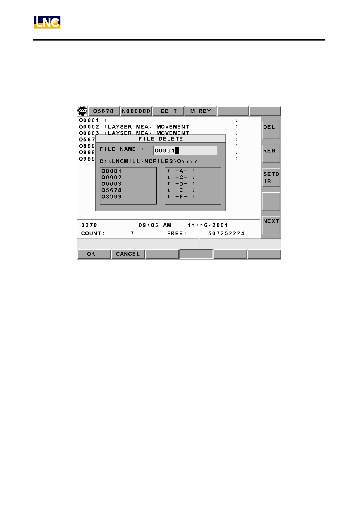
【DEL】
Pressing on this sub-function button, a file delete dialog box will appear on the screen.
Please choose the wanted delete file in that dialog box. After complete deleting, users can
use “Program Table” to confirm the result.
Figure 2.4-14 【DEL】Screen
38 LNC Technology Co., Ltd.
Page 43
LNC T520i
CNC Operation
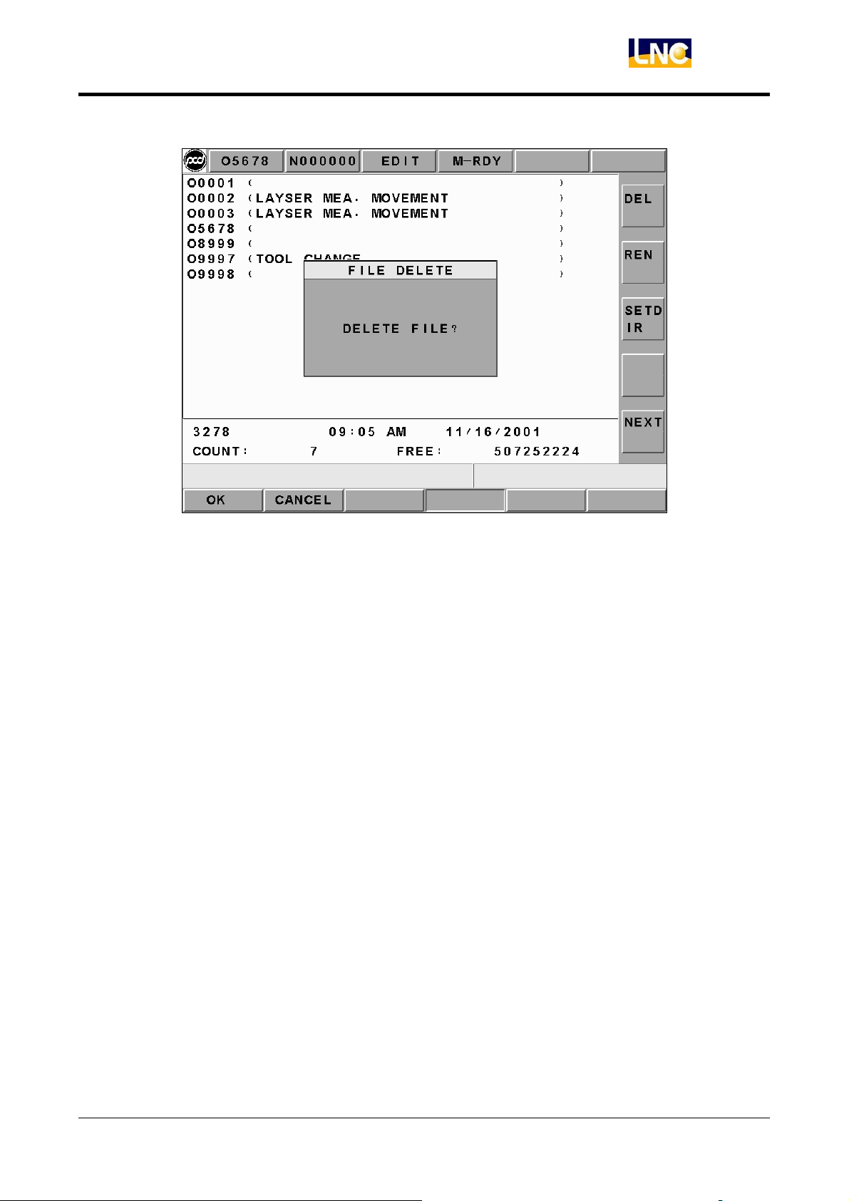
Figure 2.4-15 Double Confirmation Screen
LNC Technology Co., Ltd.
39
Page 44
LNC T520i
CNC Operation
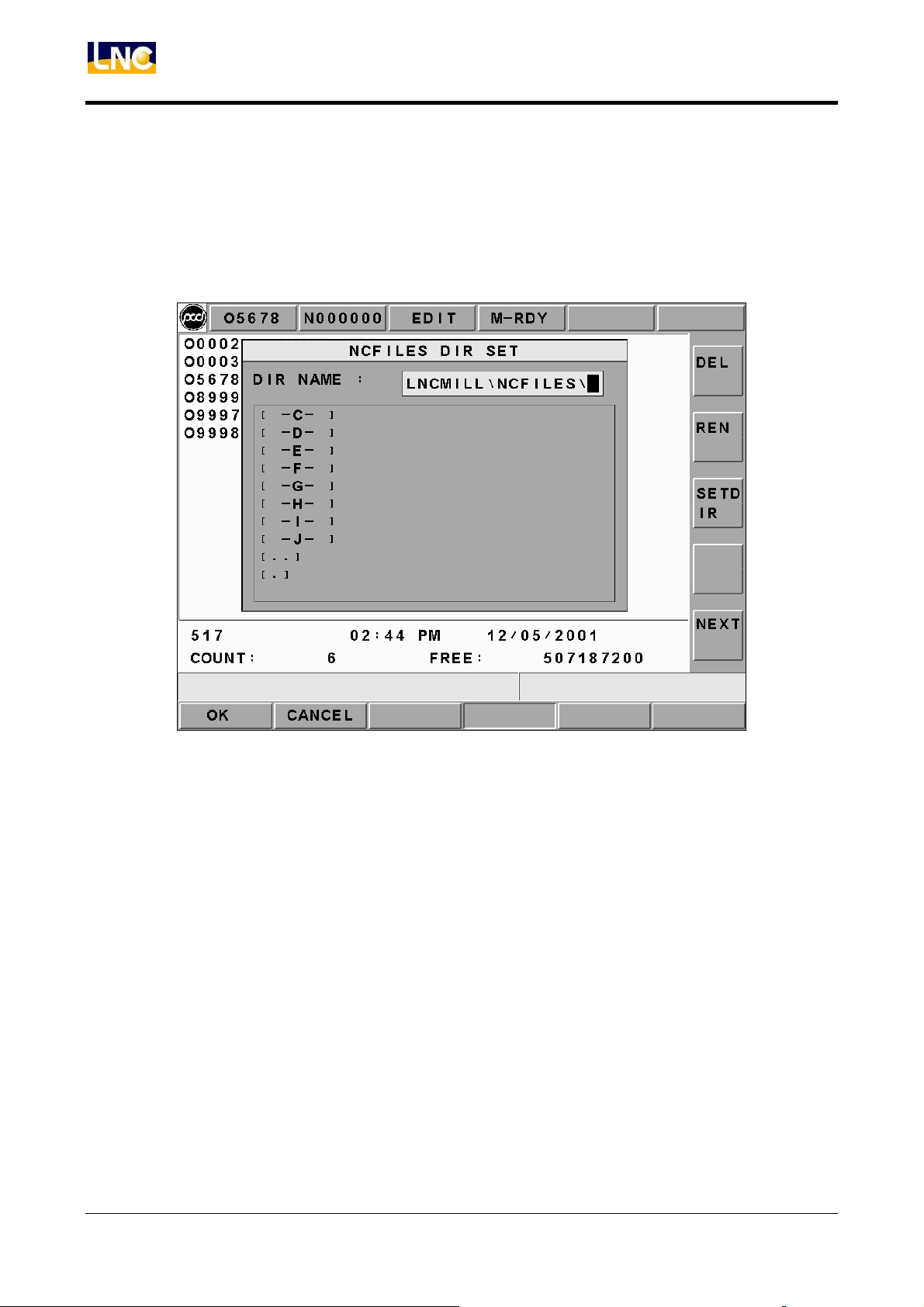
【SETDIR】
A dialog box of part program menu setting will occur on the screen by pressing this
sub-function button. Users are able to set the part program menu by using this dialog box
or by entering work path directly.
Figure 2.4-16 Setting Part Program Menu Screen
40 LNC Technology Co., Ltd.
Page 45
LNC T520i
[
CNC Operation
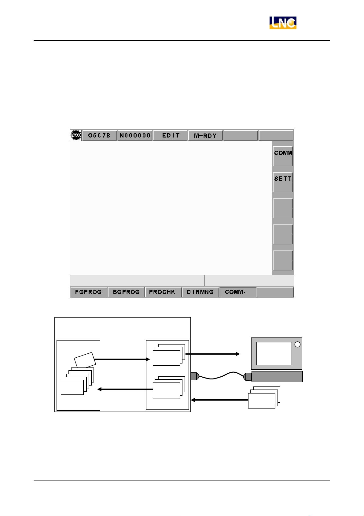
2.4.5 RS232
Clicking the【COMM.】function button to receive and transmit programs between the
controller and other PCs. Descriptions of how to operate sub-function buttons such as
【COMM】and【SETT】are as following.
LNC 520i CNC
Program store device
MMI
[SEND]
External PC
OPEN]
Files
Files
[SAVEAS]
Files
Files
[RS232]
Figure 2.4-17 【COMM.】 Screen
Figure 2.4-18 Files Transmitting/Receiving Figure between Controller and Other PCs
LNC Technology Co., Ltd.
41
Page 46

LNC T520i
CNC Operation
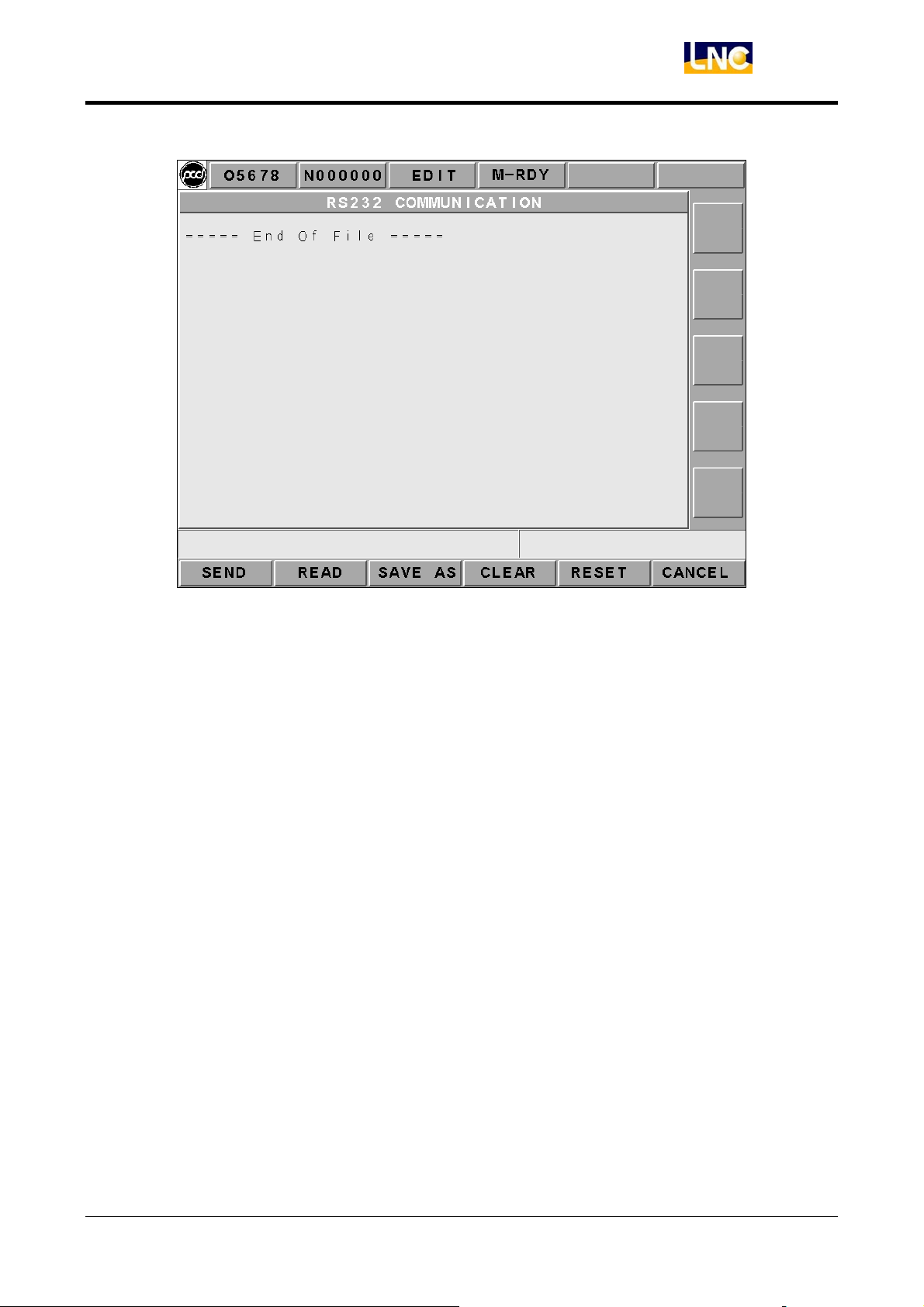
【COMM.】(Communication)
Users are able to executing RS-232 file transmitting (DNC), reading, saving, re-setting
and other operations. Before using RS232 function, please confirm whether or not the
hardware connection is correct. Also, the setting of RS232 transmitting protocol and
remote device must be the same.
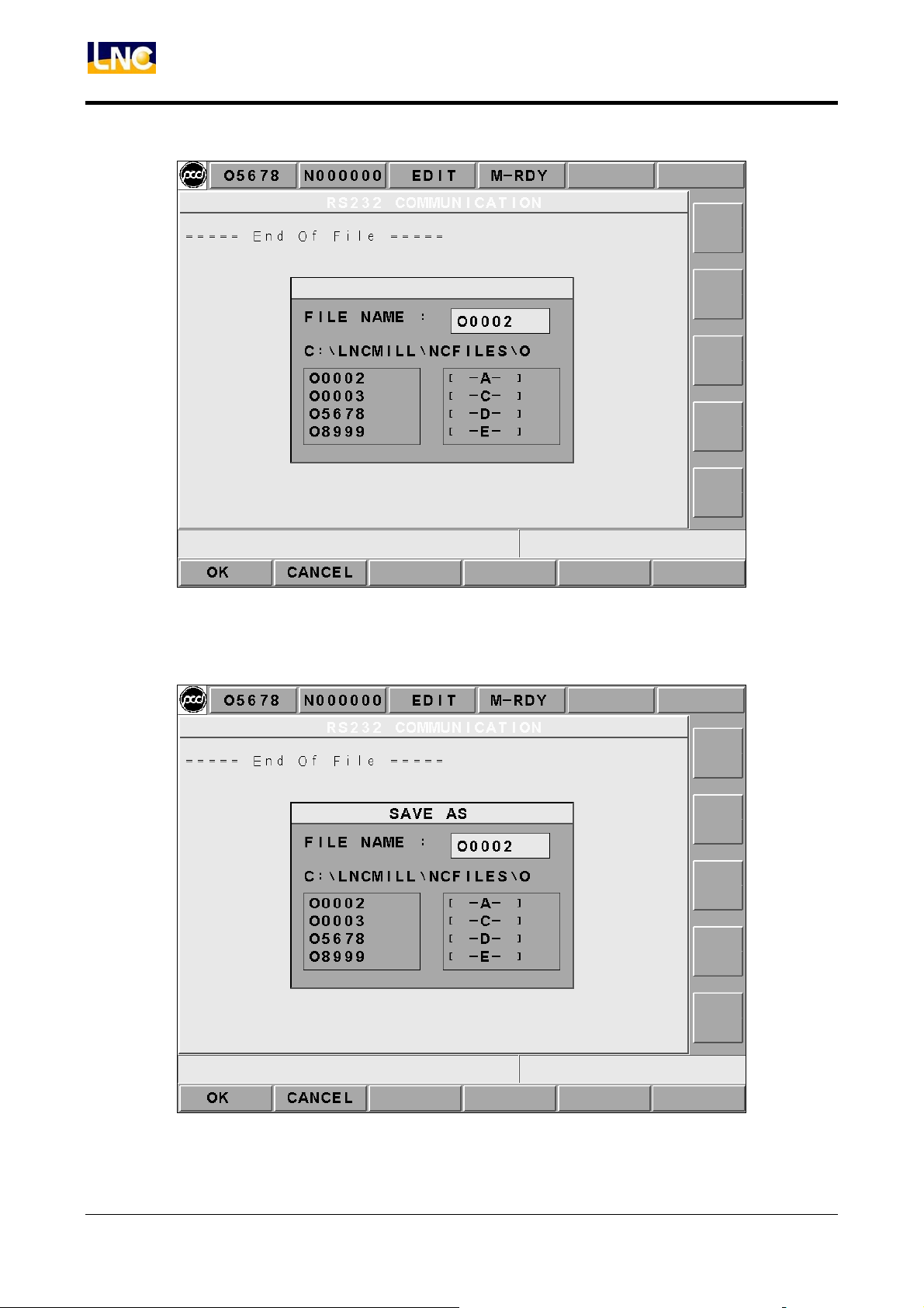
【SEND】
Pressing the transmitting button, the file selection windows will occur. Selecting the
wanted transmitting file and pressing confirm button to transmit the file via RS232. (like
Figure 2.5-20)
【SA VE AS】
When transmitting one program file to RS232 of the controller’s windows from outside,
pressing this key to select/key-in the storage path or file name directly.
【CLEAR】
Giving up and clearing program files in the windows.
【RESET】
Giving up file transmitting and resetting communication protocol in order to build up
connection with RS232.
42 LNC Technology Co., Ltd.
Page 47
LNC T520i
CNC Operation
Figure 2.4-19 Transmitting Files Screen
LNC Technology Co., Ltd.
43
Page 48
LNC T520i
CNC Operation
Figure 2.4-20 Selecting File Transmitting Function Screen
Figure 2.4-21 Screen of Save File Function
44 LNC Technology Co., Ltd.
Page 49
LNC T520i
CNC Operation
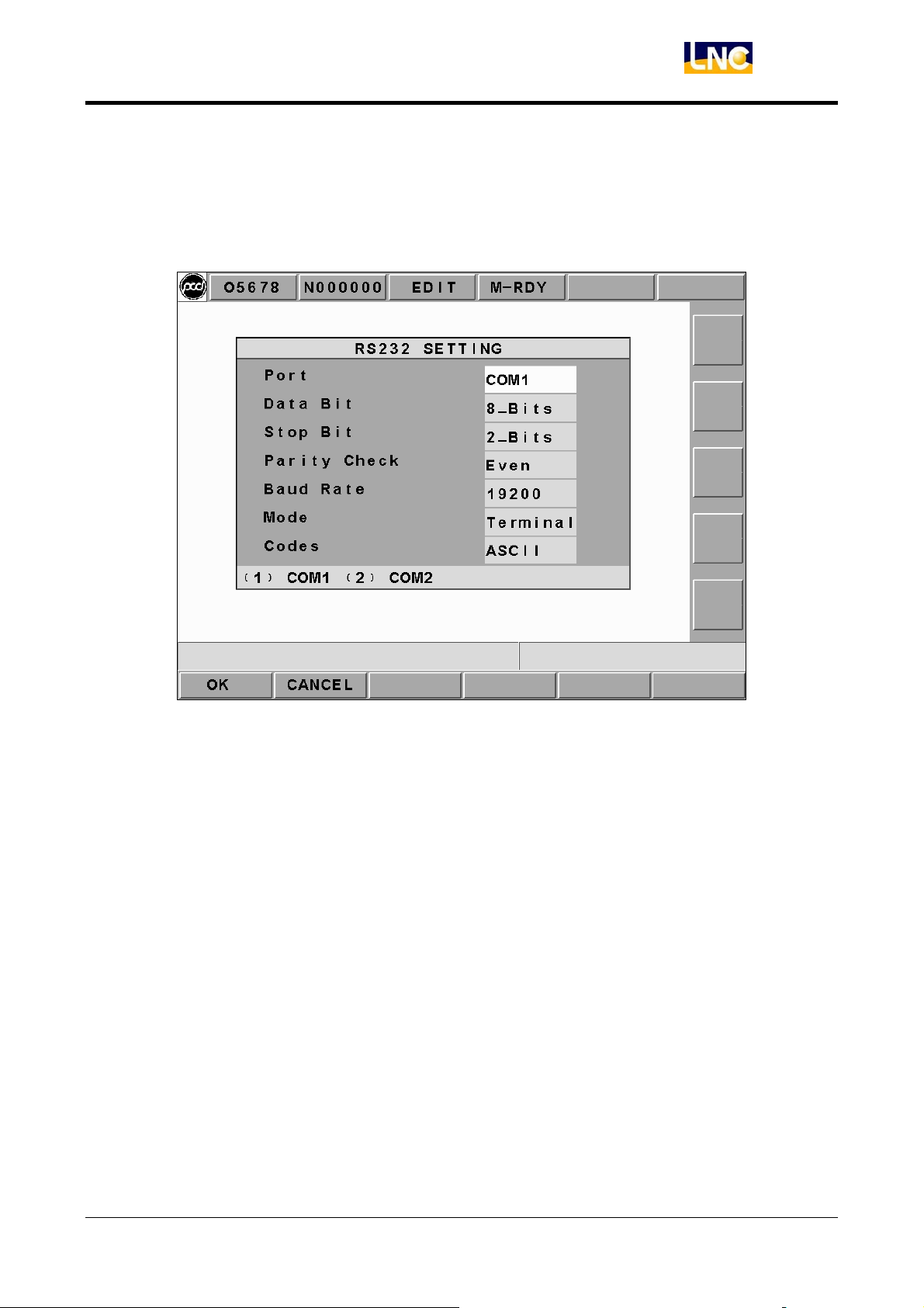
【RS232 SETTING】
This screen provides setting of RS232. The setting at each side of the RS232 transmitting
must be correct and the same in order to transmit (or so call DNC function) correctly.
Users are able to modify the transmitting protocol for RS232 on this screen.
Figure 2.4-22 RS232 Setting Screen
LNC Technology Co., Ltd.
45
Page 50

LNC T520i
CNC Operation
2.4.6 DNC Function
DNC function is a very useful function for CAD/CAM system users, especially the
controller is the controller used only (not the controller of PC BASED). Since the storage
memory capacity is not very big, so not possible to download all the programs at once.
This implies that it is very important for the DNC function to do its function while
transmitting. Since DNC program is doing its function while transmitting, so the controller
can’t edit it, neither using program calling nor using jump commanding.
In order to solve the above problems for users, Pou Yuen has installed high capacity hard
drive. Therefore, users can transmit files into the hard drive and then execute those files
(this method is called the internal DNC method.) The DNC function of executing its
functions while transmitting is the other DNC method (this method is called the external
DNC method.)
The above two methods are very convenience to use. The procedure is as below:
a. To set Controller and external PC as RS232 modal and to set the communication
protocol the same.
b. To switch to EDIT mode.
c. To press function button【COMM.】in order to enable file windows and to set file
name as RS232.
d. To switch to AUTO mode.
e. To press “CYCLE START” button on OP Panel in order to transmit CNC waiting
program.
f. To enable external PC to do RS232 file transmitting.
g. To execute machine work automatically.
46 LNC Technology Co., Ltd.
Page 51
LNC T520i
CNC Operation
2.5 OFFSET
Pressing <OFFSET> to enter into the offset function screens such as 【WEAR】, 【GEOM】,
【W. SHIFT】, 【MACRO】, and 【WORK】. Users are able to modify these settings under
MDI mode or machine ready mode.
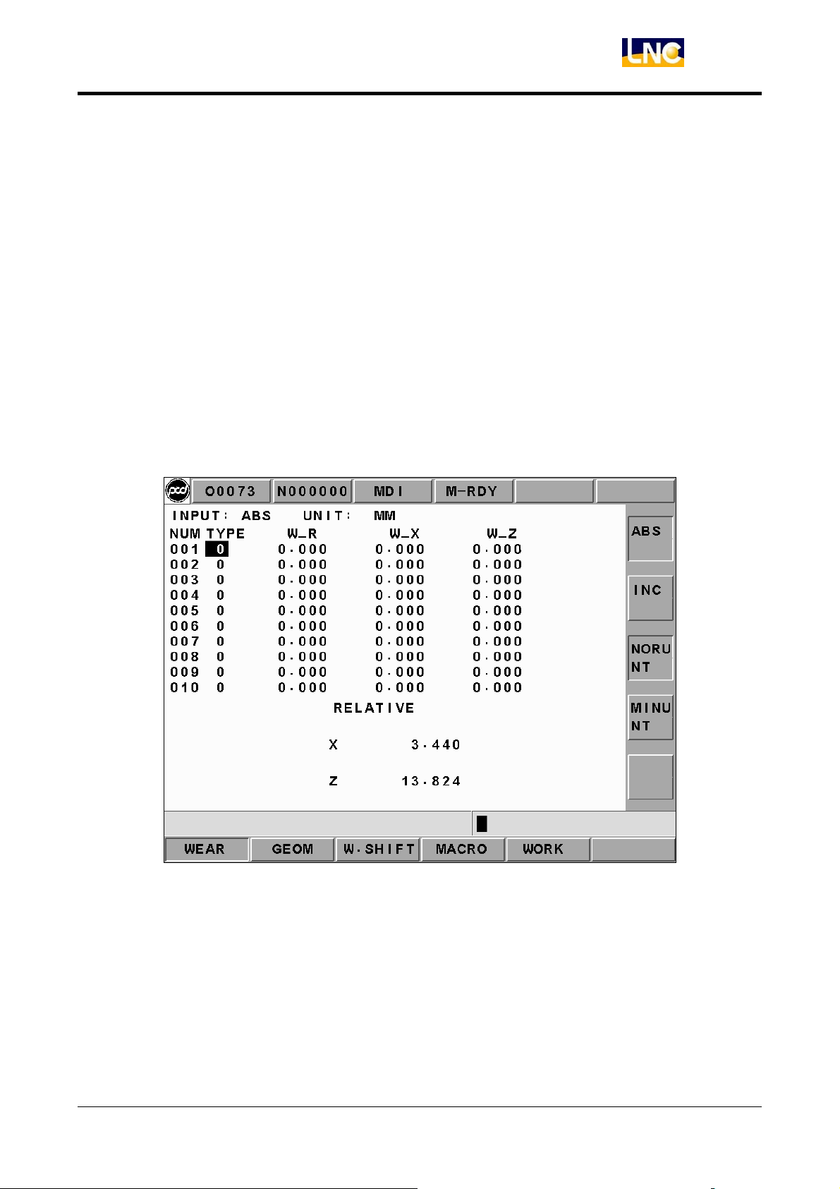
2.5.1 WEAR (Wear OFFSET)
Pressing 【WEAR】 button to enter the following screen. Also, users are able to key-in data
in MDI Mode.
LNC Technology Co., Ltd.
Figure 2.5-1 WEAR OFFSET-1
47
Page 52
LNC T520i
CNC Operation
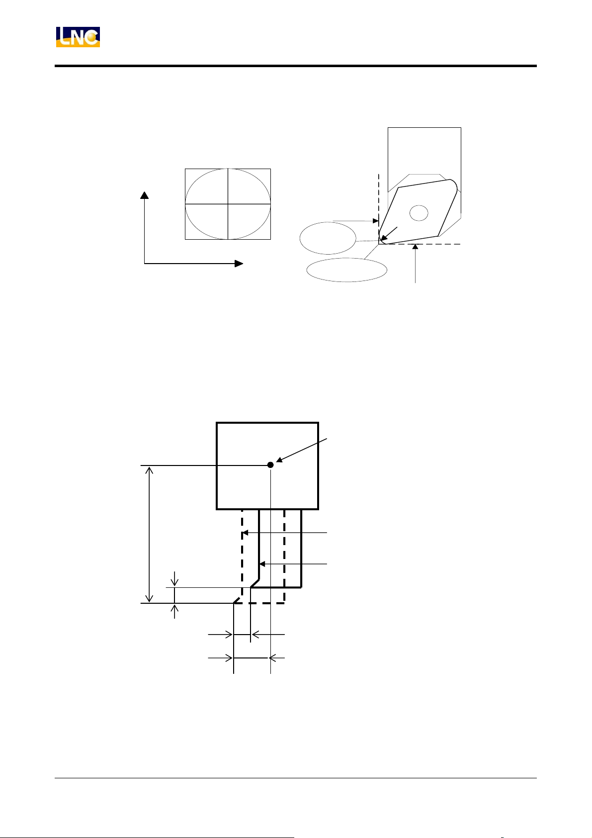
Description of Figure and each Column is as below:
Tool Type
X+
6
12
7
3 4
9 , 0
8
Z+
Type :Tool type
W_X :X axis WEAR OFFSET value
W_Z :Z axis WEAR OFFSET value
W_R :radius WEAR OFFSET value
5
Tool tip
Imaginary tool tip
Figure 2.5-2
Z
Program
Basic Point
Tool nose radius
Offset value R
X
X Axis GEOM
Imaginary Tool
Actual Tool
X Axis WEAR
Z Axis WEAR OFFSET value
Z Axis GEOM OFFSET value
Figure 2.5-3
48 LNC Technology Co., Ltd.
Page 53
LNC T520i
CNC Operation
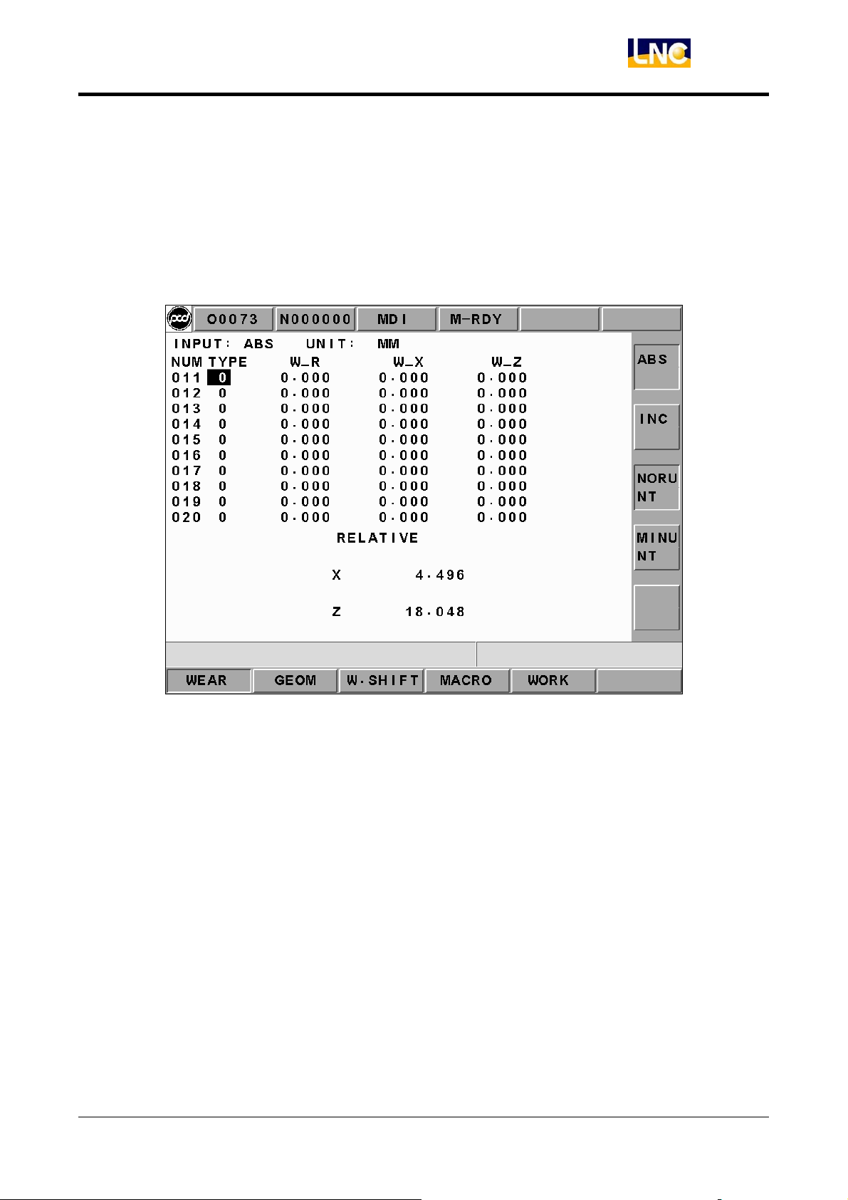
Everytime when the part program uses one tool offset number, the absolute coordinate will
change according to the tool offset value. The value is [absolute coordinate value =
machine coordinate value – external work shift - G54~G59 shift–(tool geometry offset
value + tool wear offset value)].
Pressing <PAGE↓> key to see more setting sets (max. 30 sets)
Figure 2.5-4 WEAR OFFSET-2
Moving the highlighter to the wanted setting number. Under MDI mode, key-in the setting
value and then pressing <INPUT> to write into a controller.
LNC Technology Co., Ltd.
49
Page 54
LNC T520i
CNC Operation
2.5.2 GEOM (Geometry OFFSET)
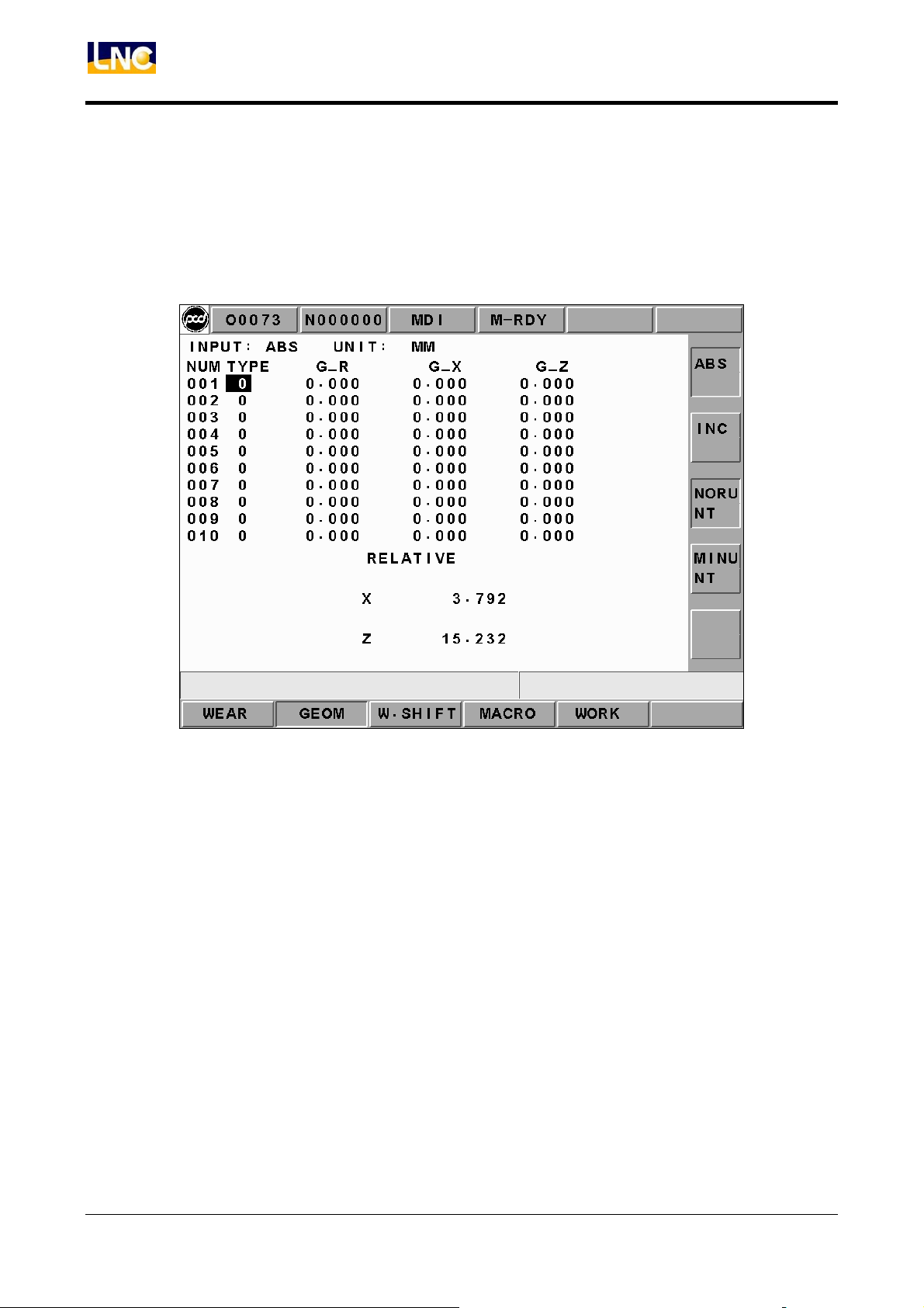
Pressing 【GEOM】 button to enter into the below screen so users are able to modify the
offset value on that screen.
Figure 2.5-5 GEOM OFFSET Screen
Type: Tool type
G_X :X Axis GEOM OFFSET value
G_Z :Z Axis GEOM OFFSET value
G_R :radius GEOM OFFSET value
Users are able to key-in the modified value directly under the conditions of MDI mode and
CNC ready. But, users are able to use “MXxx” and “MZzz” to set the offset value for G_X
and G_Z. The calculation method is as following:
Offset value = Machine coordinate value – external w o rk shi ft - G54~G59 shift – key-in value.
50 LNC Technology Co., Ltd.
Page 55
LNC T520i
CNC Operation
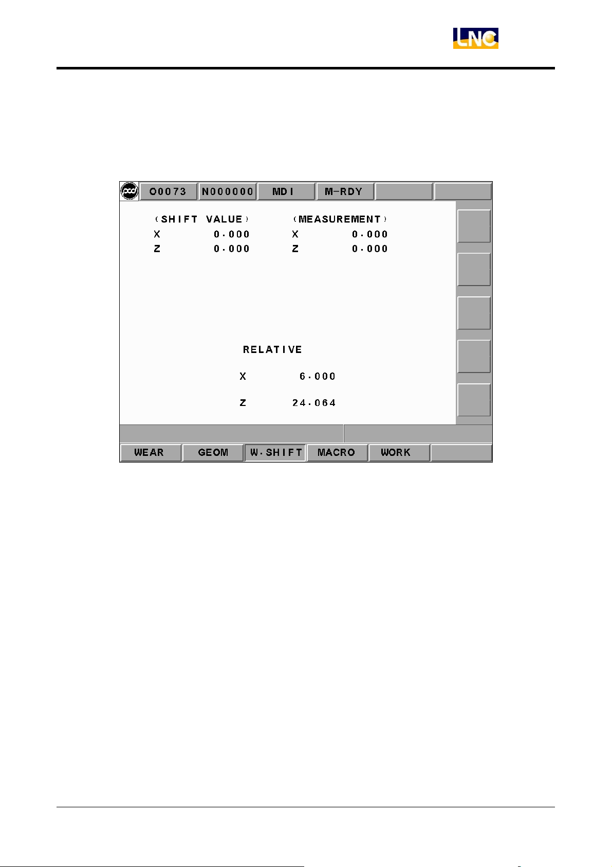
2.5.3 W. SHIFT (Work Coordinate Shift)
Pressing 【W. SHIFT】 button to enter into the setting screen of the work shift function.
Figure 2.5-6 Setting WORK SHIFT Screen
Two key-in value methods under MDI mode. The description is as below:
Method 1: Key-in the shift amount for each axis directly, key-in “X20. Z20.” first. Then,
pressing 【ENTER】 to update the new entry value into the shift value. So shift
value = entry value.
Method 2: Key-in the estimating value. Please key-in “MXxx MZzz” first and then pressing
【ENTER】 to update the new entry value into the estimating value column. So
estimating value = entry value.
The calculation of shift value is “Shift value = machine coordinate value – entry value -
G54~G59 shift – (wear offset value + geometry offset value).”
LNC Technology Co., Ltd.
51
Page 56
LNC T520i
CNC Operation
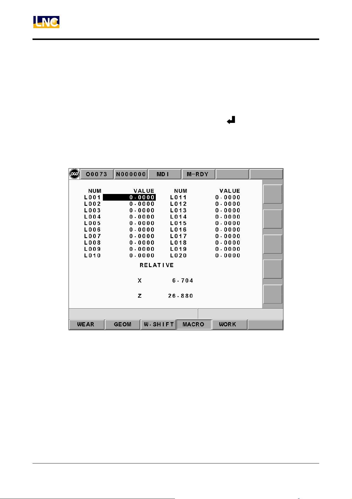
2.5.4 MACRO
Pressing 【MACRO】 button to enter into the MACRO variable screen. In this function
page, variables can be entered or modified. The modification method is to move the
highlighter to the wanted modify position and then to press<> button after entering the
wanted value. Variables that start with L are local variables and those start with C are
common variables. Please refer to MACRO chapter of program manual for a detailed
description.
Figure 2.5-7 Local Variables of MACRO Variables
52 LNC Technology Co., Ltd.
Page 57
LNC T520i
CNC Operation
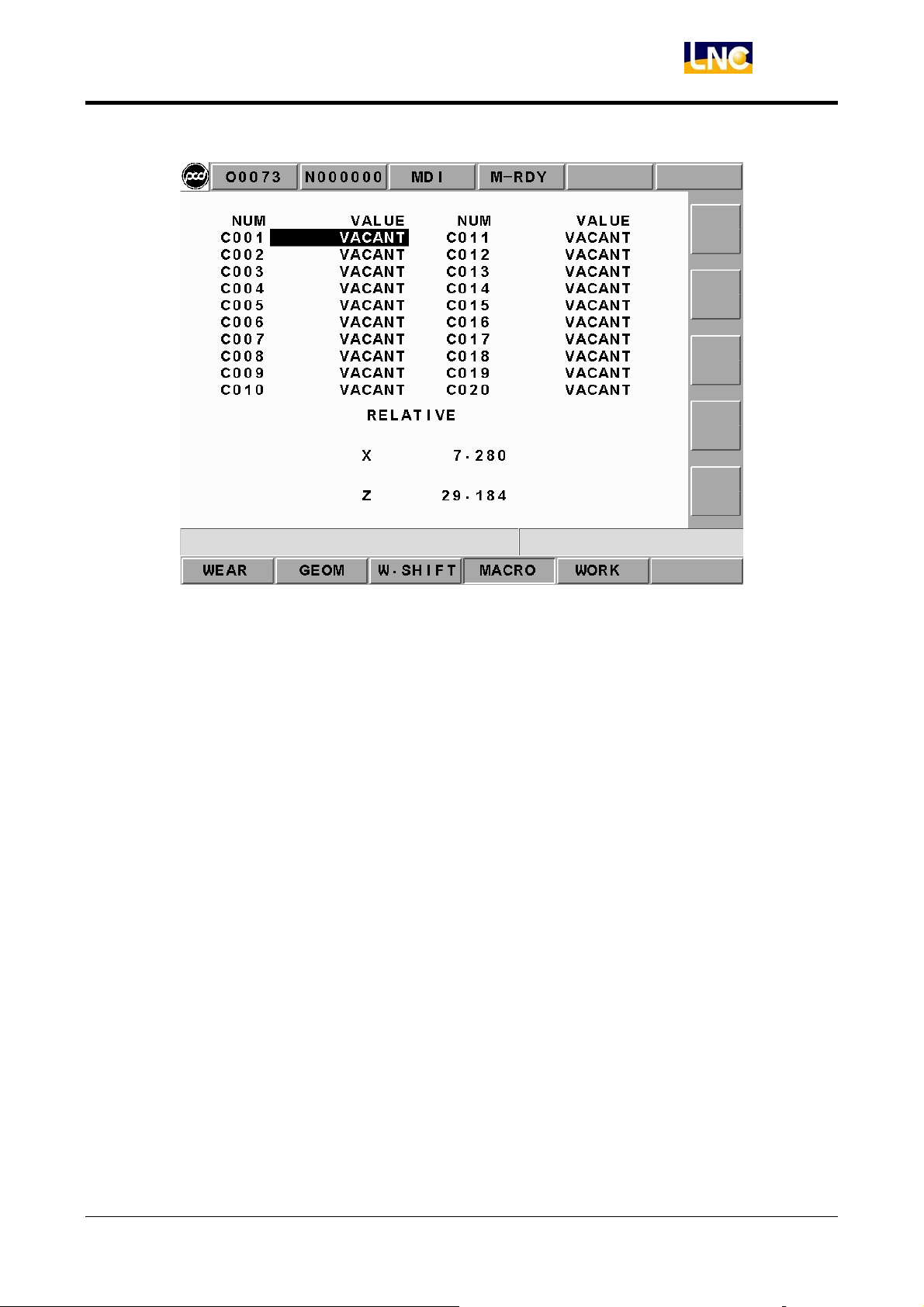
Figure 2.5-8 System Variables of MACRO Variables
LNC Technology Co., Ltd.
53
Page 58

LNC T520i
CNC Operation
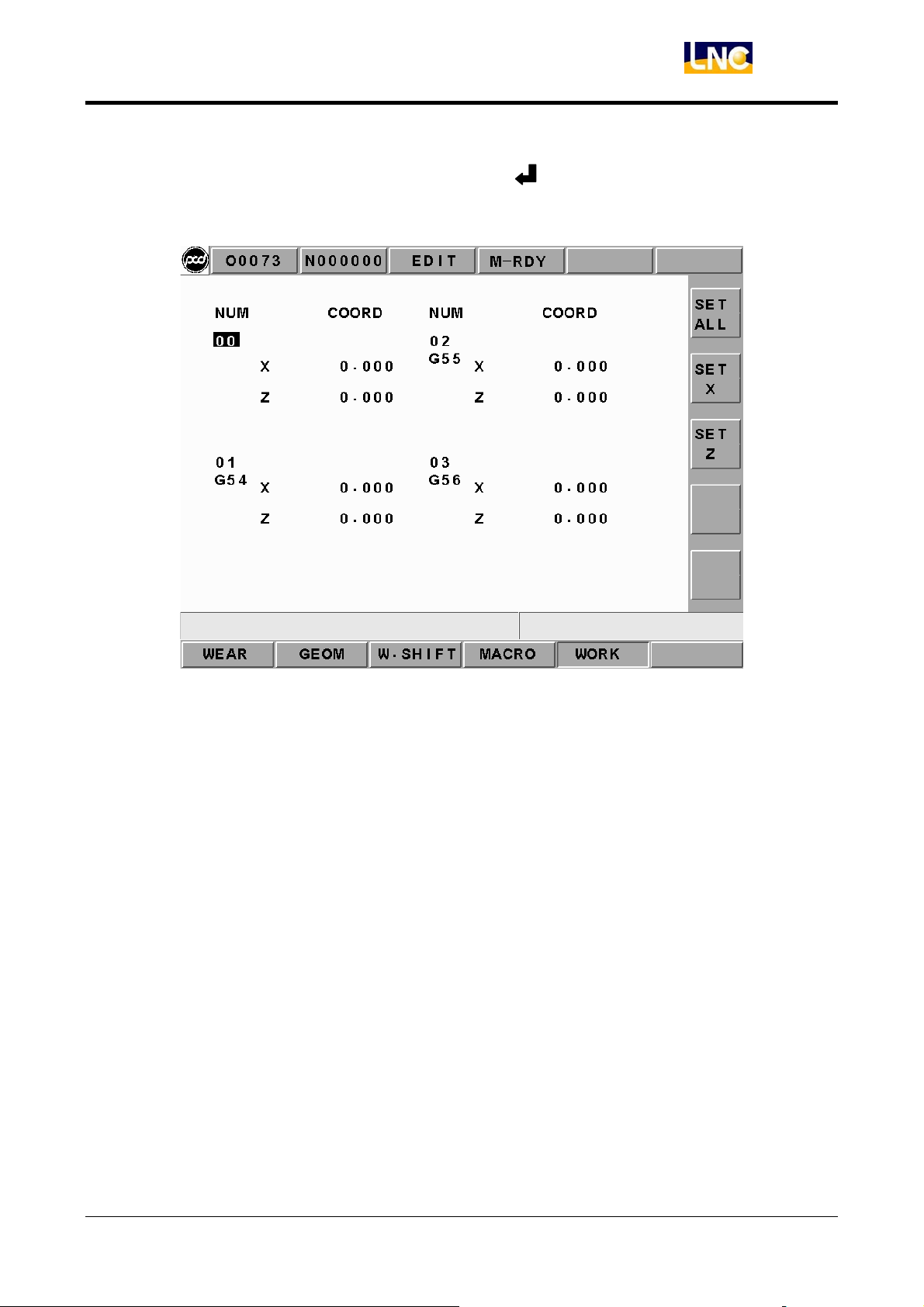
2.5.5 WORK (Coordinate Setting)
Pressing 【WORK】 to enter into the setting screen of the work coordinate system. There
are 7 sets of work coordinate system for setting, which indicate extending shift for G54 ~
G59. In MDI mode, users are able to use cursor to identify group. Also, after key-in
Xxx..Zzz…, users can press <> to renew the coordinate value in order for part program
in different coordinate system.
Extending shift setting will directly affect other 6 coordinate systems (G54 to G59).
Please see the following for description:
# 01: G54 machine coordinate value of the reference point = #01 setting value + #(00)
setting value
# 02: G55 machine coordinate value of the reference point = #02 setting value + #(00)
setting value
# 03: G56 machine coordinate value of the reference point = #03 setting value + #(00)
setting value
# 04: G57 machine coordinate value of the reference point = #04 setting value + #(00)
setting value
# 05: G58 machine coordinate value of the reference point = #08 setting value + #(00)
setting value
# 06: G59 machine coordinate value of the reference point = #06 setting value + #(00)
setting value
54 LNC Technology Co., Ltd.
Page 59
LNC T520i
CNC Operation
Additional example: key-in x-256.5, and pressing < > will set –256.5 to the x coordinate
value on the assigned cursor set.
Figure 2.5-9 Work Coordinate Setting Screen-1
LNC Technology Co., Ltd.
55
Page 60
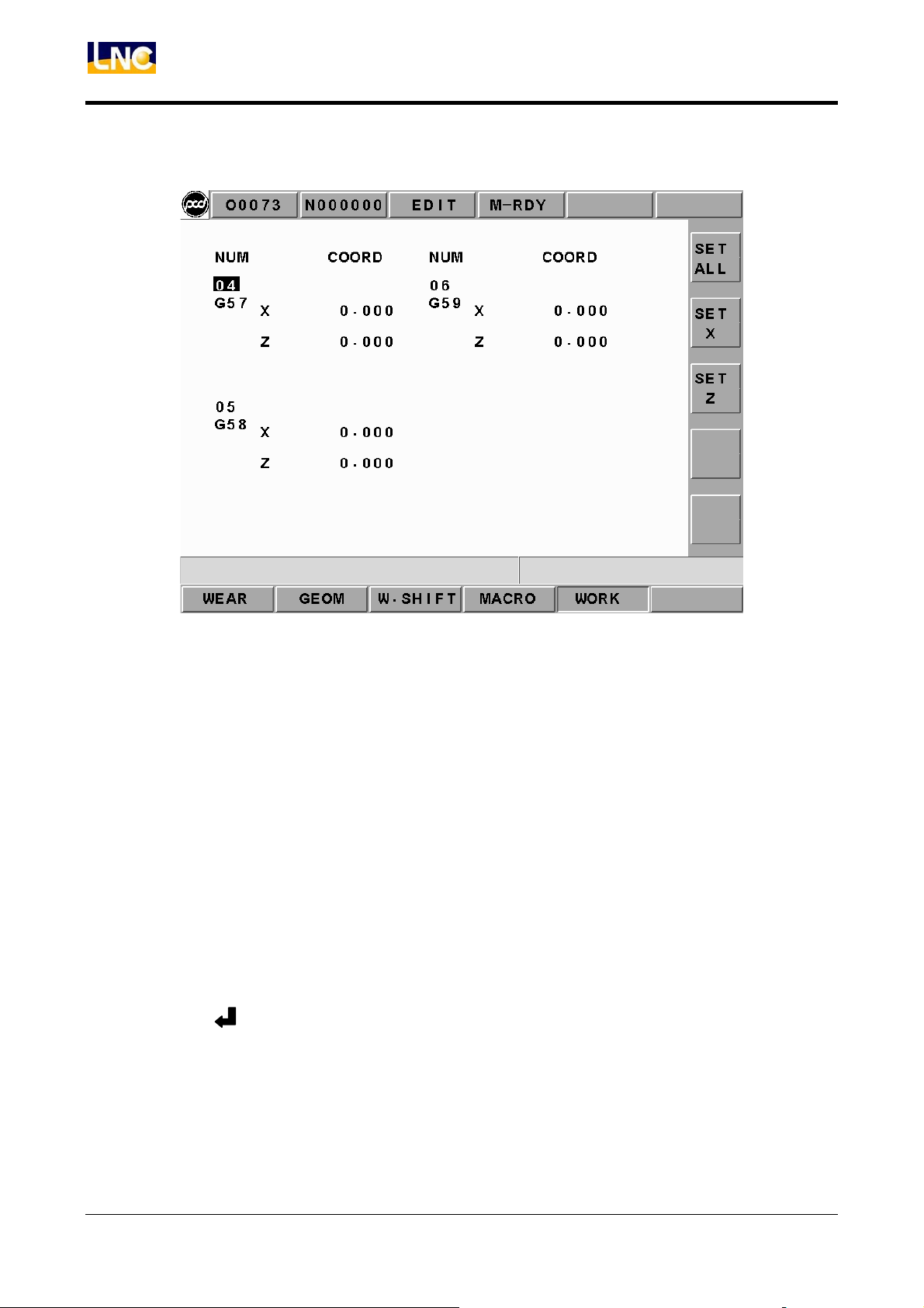
LNC T520i
CNC Operation
Pressing <PAGE↓> to view the next page.
Figure 2.5-10 Work Coordinate Setting Screen-2
Extending shift setting will directly affect other 6 coordinate systems (G54 to G59). When
setting, please consider work piece coordinate, tool and program executing relationships.
If want to reset one coordinate system:
a. Moving the cursor key to the wanted setting number of the coordinate system.
b. Key-in the axis name and the new coordinate value, users are able to write 3 axes
continuously. But, remember to put decimal point in order to prevent confusion.(i.e.,
X100. Z200.)
c. Pressing < > to key-in the value into controller.
56 LNC Technology Co., Ltd.
Page 61

LNC T520i
CNC Operation
2.6 Lathe EASY-CAM
2.6.1 Function Description
Users only need to key-in the needed working information and then to press【NC Gear
Shifting】button to produce working path program automatically. There are 14 working
methods of this function for users to choose. Each working method must be used with
different parameter according to its feature in order to produce correct working path
program.
2.6.2 Operation Procedure of How to Produce Working Path Program
1. Open a New Project File
Pressing 【DIRMNG】button on the main function screen to change the screen to the
file management screen. Pressing【New】button on the project management screen
and key-in the project name into the entry column and then pressing【OK】button. The
screen will change to the main function screen after opening file successfully.
2. New Procedure
Pressing【PROC ADD】button on the main function screen.
3. Working Method Selection
Pressing 【ENTER】button when yellow cursor occurs at the working method column
and a working method selection menu will popup. Using 【UP】 or 【DOWN】 key to
select the needed working method and then pressing 【ENTER】 or 【OK】 button.
Then, the selected working method will appear on the working method column.
4. Tool Number Selection and Tool Information Key-In
When the yellow cursor occurs at the tool number column, pressing【ENTER】button to
change the screen to the tool setting screen. Key-in the needed information according
to different working method and then pressing【ENTER】button. After that, pressing
【RTN】 button to change the screen to the main function screen. The chosen tool
number will appear on the tool number column.
LNC Technology Co., Ltd.
57
Page 62

LNC T520i
CNC Operation
5. Key-in Head Parameter Info
When the yellow cursor occurs at the head parameter column, pressing【ENTER】key
to switch the screen to the head parameter screen. After key-in the needed head
parameter data, pressing 【ENTER】key to switch the screen back to the main function
screen. Then, a blue “DEFINE” will occur on the head parameter column.
6. Key-in Cutting Parameter Information
When the yellow cursor occurs at the cutting parameter column, pressing【ENTER】
button to change the screen to the cutting parameter screen. After key-in the needed
cutting parameter data, pressing【RTN】button to change the screen back to the main
function screen. Blue characters, “Define”, will appear on the parameter column.
7. Key-in Geometry Define Information
When the yellow cursor occurs at the geometry define column, pressing 【ENTER】
button to change the screen to the geometry define screen. After key-in the needed
geometry define data, pressing【RTN】button to change the screen to the geometry
define screen. Then, blue characters, “Define”, will appear on the geometry define
column.
8. After the above seven steps, users can press 【SAVE】 to save the project. Or,
pressing【NC Gear Shifting】to produce the working path program.
58 LNC Technology Co., Ltd.
Page 63
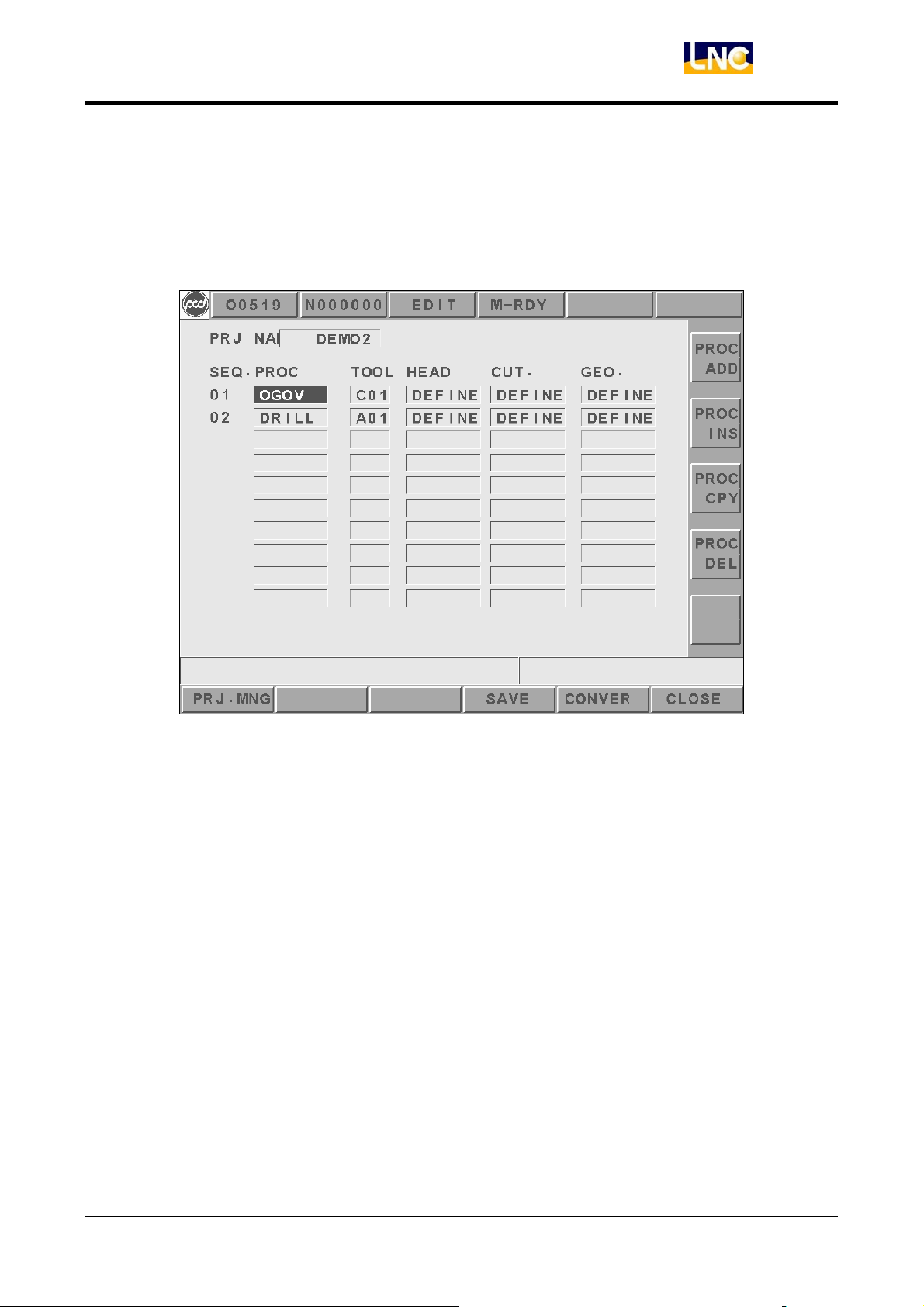
2.6.3 Operation Screen and Function Key Instruction
◎ Main Function, the screen is as below:
LNC T520i
CNC Operation
Figure 2.6-1 Main Function Page
【Column Description】
※ Project Name:Display the currently opened project name.
※ Procedure:Display procedure order number. The system will auto edit this column.
※ Working Method:Display the selected working name. A “clear working name” dialog
box will be popup when users press【ENTER】key at this column.
※ Tool #:Display the selected tool number. The screen will switch to the tool setting
screen when users press 【ENTER】at this column. 4 types of tool number, which are A
type for drilling tool, B type for profile lathe tool, C type for grooving tool, D type for
screwing tool. Number means the tool number from the tool list on the tool setting
page.
LNC Technology Co., Ltd.
59
Page 64

LNC T520i
CNC Operation
※ Head Parameter:Red indicates “un-define” and blue indicates “define”. “Un-define”
means users select to enter into the head parameter screen that never been in before.
On the other hand, “define” means users have been to the head parameter screen.
Screen will switch to the head parameter screen when users press【ENTER】key at this
column.
※ Cutting Parameter:Red indicates “un-define” and blue indicates “define”. “Un-define”
means the cutting parameter screen that users haven’t been in before. On the other
hand, “define” means users have been to the head parameter screen. Screen will
switch to the cutting parameter screen when users press【ENTER】key at this column.
※ Geometry Define:Red indicates “un-define” and blue indicates “define”. “Un-define”
means the geometry define screen that users haven’t been in before. On the other
hand, “define” means users have been to the geometry define screen. Screen will
switch to the geometry screen when users press 【ENTER】 key at this column. Screen
will switch to different geometry setting screens according to different working
methods.
【Function Keys at Screen Bottom】
※ PRJ. MNG:Switching screen to the project management windows.
※ SAVE:Saving the currently opened project.
※ CONVER:Switching the currently opened project data to the work path program.
※ CLOSE:Closing the currently opened project.
【Function Key at Right of Screen】
※ PROC ADD :Adding a new program to the next row of the row where the yellow cursor
occurs.
※ PROC INS:
Insert a new program to the previous row of the row where the yellow
cursor occurs.
※ PROC CPY:Copy a row of program where the yellow cursor occurs to the next row of
the copied row.
※ PROC DEL:Delete all procedures where yellow cursor occurs.
60 LNC Technology Co., Ltd.
Page 65
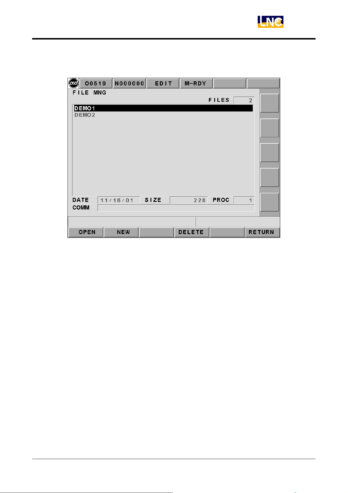
◎ Screen of Project Management is as below:
LNC T520i
CNC Operation
Figure 2.6-2 Project Management Page
【Column Description】
※ Project #:Display the current project number.
※ Display Dialog Box: Display all project list.
※ Project Date:Display the project date where the yellow cursor occurs.
※ File Size:Display the file size where the yellow cursor occurs.
※ Procedure #:Display the total procedure # of a project where the yellow cursor occurs.
※File Description:display the project description where the yellow cursor occurs. Pressing
【LEFT】 or 【RIGHT】key to move the yellow cursor to the column. Then, key-in data
into that column and press 【ENTER】key to write “NOTE” for the project.
LNC Technology Co., Ltd.
61
Page 66

LNC T520i
CNC Operation
【Function Keys at Screen Bottom】
※ OPEN:Downloading a project where the yellow cursor occurs and switching to the
main function page.
※ NEW:Building a new project name and the screen will switch to the main function
screen after confirm the key-in project name.
※ DELETE:Deleting a project where yellow cursor occurs.
※ RETURN:Switching screen to the main function screen.
【Function Keys at Right of Screen】
※ Confirm:Pressing 【NEW】 or 【DEL】 key at screen bottom for the confirm key to
occur. Pressing 【NEW】key at the screen bottom. Then pressing【OK】to open the new
file and to switch the screen to the main function screen. Pressing 【OK】after pressing
【DEL】key at the screen bottom, the project where the yellow cursor occurs will be
deleted.
※ Cancel:Pressing 【OPEN】 or 【DEL】 key at the screen bottom first. Then, pressing
【DEL】 key after pressing 【OPEN】 key at screen bottom to cancel opening new file.
Pressing 【CANCEL】 key after pressing 【DEL】 key at screen bottom to cancel
deleting file.
62 LNC Technology Co., Ltd.
Page 67
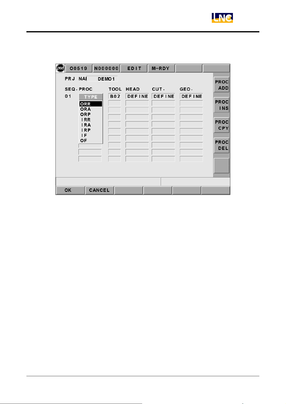
◎ Screen of Working Method is as below:
LNC T520i
CNC Operation
Figure 2.6-3 Working Method Page
LNC Technology Co., Ltd.
63
Page 68

LNC T520i
CNC Operation
【Column Description】
※ Working Method List:display a list of 14 types working methods as below show:
1. DRILL: drilling one internal hole on the material
2. ORR: Outer Rough Diameter
3. ORA: Outer Stock Removal in Turning
4. ORP: Outer Pattern Repeating
5. IRR: Internal Rough Diameter
6. IRA: Internal Stock Removal in Turning
7. IRP: Internal Pattern Repeating
8. IF: Internal Finishing Cycle
9. OF Outer Finishing Cycle
10. OGOV: Grooving on Outer Surfaces
11. IGOV: Grooving on Inter Surfaces
12. FGOV: Grooving on End Faces
13. OSEW: External Thread Cutting
14. ISEW: Internal Thread Cutting
Description of Each Working Method is as below:
☉ Drilling:drilling one internal hole on the material
☉ ORR: outer rough diameter. Cutting most of material part that is made by straight
line and arch. Tool moving direction is according to the perpendicular Z-axis
direction
☉ ORA:outer stock removal in turning. Clearing the most material part that is made by
line and arch. Tool moving direction is according to the perpendicular X-axis
direction.
☉ ORP: outer pattern repeating. Clearing the most material of the pattern that is made
by straight line and arch. Tool moving direction is according to the curve outline.
☉ IRR: internal rough diameter. Cutting most of material part that is made by straight
line and arch. Tool moving direction is according to the perpendicular Z-axis
direction.
☉ IRA:internal stock removal in turning. Clearing the most material part that is made
by line and arch. Tool moving direction is according to the perpendicular X-axis
direction.
64 LNC Technology Co., Ltd.
Page 69

LNC T520i
CNC Operation
☉ IRP: internal pattern repeating. Clearing the most material of the pattern that is
made by straight line and arch. Tool moving direction is according to the curve
outline.
☉ IF:internal finishing cycle. Clearing the rest of the material of the outline that is
combined by straight line and arch.
☉ OF:outer finishing cycle. Clearing the rest of the material of the outline part that is
combined by straight line and arch.
☉ OGOV:grooving on outer surfaces,. Using grooving tool to cut a concave shape on
the working piece. Outer surface, inter surface or end-faces is according to the
grooving position.
☉ IGOV:grooving on internal surface. Using grooving tool to cut a concave shape on
the working piece. Outer surface, inter surface or end-faces is according to the
grooving position.
☉ FGOV:grooving on end faces. Using grooving tool to cut a concave shape on the
working piece. Outer surface, inter surface or end-faces is according to the grooving
position.
☉ OSEW:external thread cutting. Cutting thread horizontally and selecting feeding
method according to the using method.
☉ ISEW:internal thread cutting. Cutting thread horizontally and selecting feeding
method according to the using method.
【Function Key at Screen Bottom】
※ Confirm:selecting the working method where the yellow cursor is at. Switching to the
main function screen and then displaying the selected working name on the working
method column.
※ Cancel:cancel selecting working method action and switch screen to the main function
screen.
【Function Key at Right of Screen】
None.
LNC Technology Co., Ltd.
65
Page 70
LNC T520i
CNC Operation
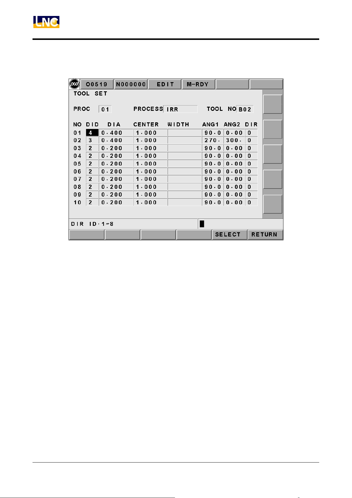
◎ Screen of Tool Setting is as below screen:
Figure 2.6-4 Tool Setting Page
【Column Description】
※ Procedure:Display the present editing procedure order number.
※ Working Method:Display the working method name of the present editing procedure.
※ Tool NO.:Display the selected tool NO. of the present editing procedure. 4 types of
tool NO. Type A for drilling tool, Type B for pattern tool, Type C for grooving tool, and
Type D for thread tool. The number should be the tool NO. from the tool clear list of the
screen.
※ Tool Clear Dialog Box at Screen Bottom: Able to display and edit 10 sets of data.
Users need to key-in different columns according to different working methods. The
description of each column is as below:
☉ Tool NO.:Tool parameter number, The same type, able to do CAM calculation
according to difference parameter. Selecting the NO. 1 tool parameter when one
tool is at the first procedure. But, for the 2nd procedure, users can select the 2nd tool
parameter for CAM calculation.
66 LNC Technology Co., Ltd.
Page 71
LNC T520i
CNC Operation
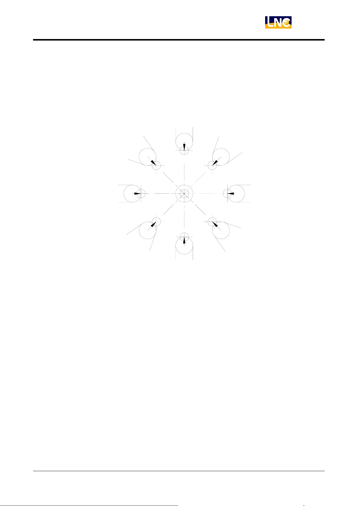
☉ Tool Direction:Tool noise direction, which is the imagery tool tip direction. Using 10
numbers (number 0~9) to indicate the corresponding position of the imagery tool
tip and tool noise center point. Like Figure 2.6-5, arrowhead position is the tool tip
point. Tool tips of imagery Tool # 0 and #9 is overlap with tool noise center point.
lmaginary tool
nose number 6
lmaginary tool
nose number 2
lmaginary tool
nose number 7
lmaginary tool
nose number 3
lmaginary tool nose
lmaginary tool
nose number 0,9
lmaginary tool
nose number 8
lmaginary tool
nose number 1
lmaginary tool
nose number 5
lmaginary tool
nose number 4
Figure 2.6-5 Corresponding Position Figure of Imagery Tool Tip Point and Tool Noise Center Point
LNC Technology Co., Ltd.
67
Page 72

LNC T520i
CNC Operation
☉Tool Radius: Tool noise radius. The below Figure is the tool tip after scaling in.
radius
Figure 2.6-6 Scale-In Figure of Tool Tip
☉ Radius: The below Figure is the internal radius of tool.
R
Figure 2.6-6 Internal Tool Radius
☉ Tool Width:Tool width.
☉ Feed Angle:Feel angle. To set the needed setting column, external pattern, axis,
wheel and fine-lathe to 90 and to set the internal pattern, axis, wheel and fine-lathe
to 270.
☉ Cutting Angle:The max. effective cutting angle. To set the needed setting column,
external pattern, axis, wheel and fine-lathe within the range of 0~90 when doing
profile cutting and to set the internal pattern, axis, wheel and fine-lathe within the
range of 270~360.
☉ Rotary Direction: Spindle rotary direction, clockwise (CW) or counter clockwise
(CCW).
68 LNC Technology Co., Ltd.
Page 73
LNC T520i
CNC Operation
【Function Keys at Bottom at the Screen】
※ Selection:select the needed tool parameter data, tool number at the upper screen
indicates the selected tool number.
※ Return:switch to the main function screen.
【Function Keys at Right of the Screen】
None.
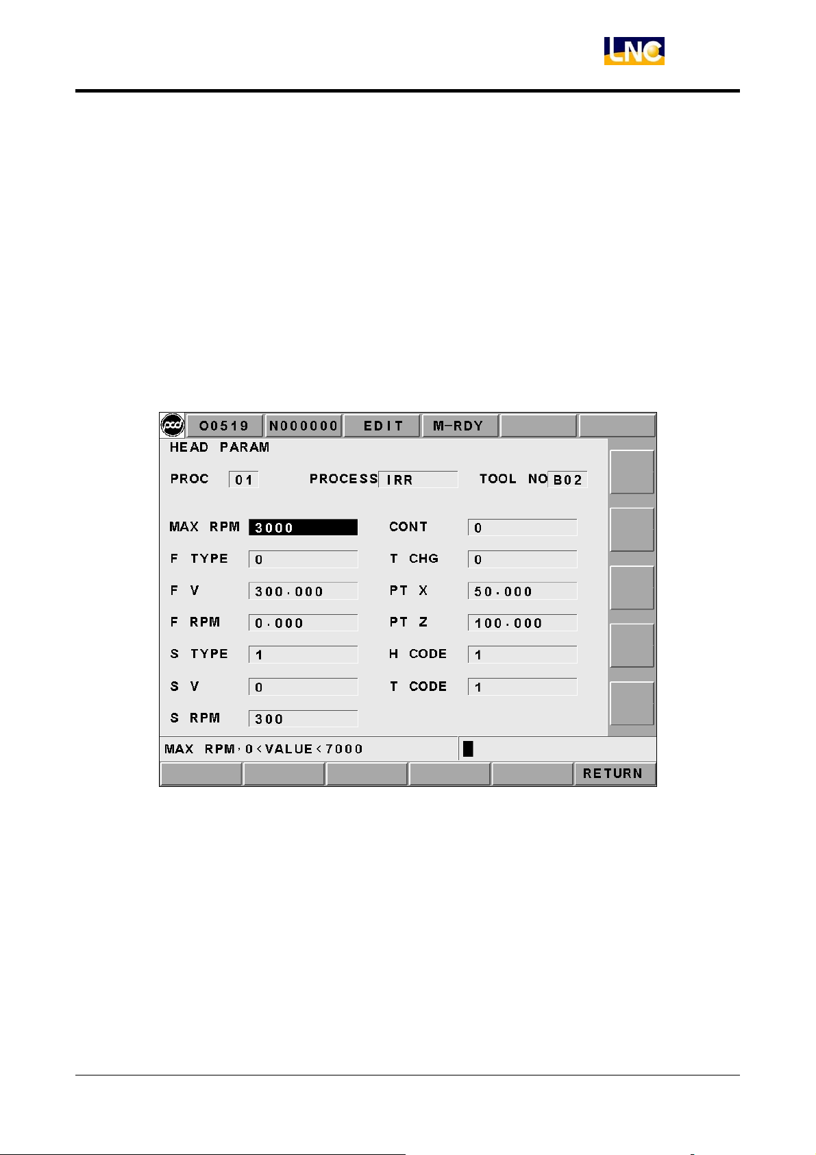
◎ Screen of Head Parameter is as below:
Figure 2.6-7 Header Parameter Page
【Column Description】
※ Procedure:Display the currently editing procedure number.
※ Working Method: Display the working method name of the currently editing
procedure.
※ Tool NO.:Display the selected tool NO. of the currently editing procedure. 4 types of
tool NO. Type A for drilling tool, Type B for pattern tool, Type C for grooving tool, and
Type D for thread tool. The number should be the tool NO. from the tool clear list of the
screen.
LNC Technology Co., Ltd.
69
Page 74

LNC T520i
CNC Operation
※ Head Parameter Column:Users can key-in an appropriate value according to the
actual need.
☉ Max. RPM:Spindle max. rotational speed
☉ F TYPE:0 means using feed/min, 1 means using feed/rotate.
☉ F V:When the feed unit is selected as 0, users must key-in any value that is larger
than 0 into this column.
☉ F RPM:When the feed unit is selected as 1, users must key-in any value that is
larger than 0 into this column.
☉ S TYPE:0 means using fixed cutting speed, 1 means using fixed rotating speed.
☉ S V: When fixed cutting/rotate is selected as 0, users must key-in any value large
than 0 into this column.
☉ S RPM:When fixed cutting/rotate is selected as 1, users must key-in any value
larger than 0 into this column.
☉ CONT:Whether or not to use cutting liquid. 0 means no need to use it, 1 means use
it.
☉ T CHG:0 means not need to use tool-exchanging point, 1 means use the user
default tool-exchanging point.
☉ PT X:User default of tool-exchanging X coordinate.
☉ PT Z:User default of tool-exchanging Z coordinate.
☉ H Code: Tool OFFSET number.
☉ T Code: Actual tool number on turret.
【Function Keys at Screen Bottom】
※ Return: switch to the main function screen.
【Function Keys at Right of the Screen】
None.
70 LNC Technology Co., Ltd.
Page 75
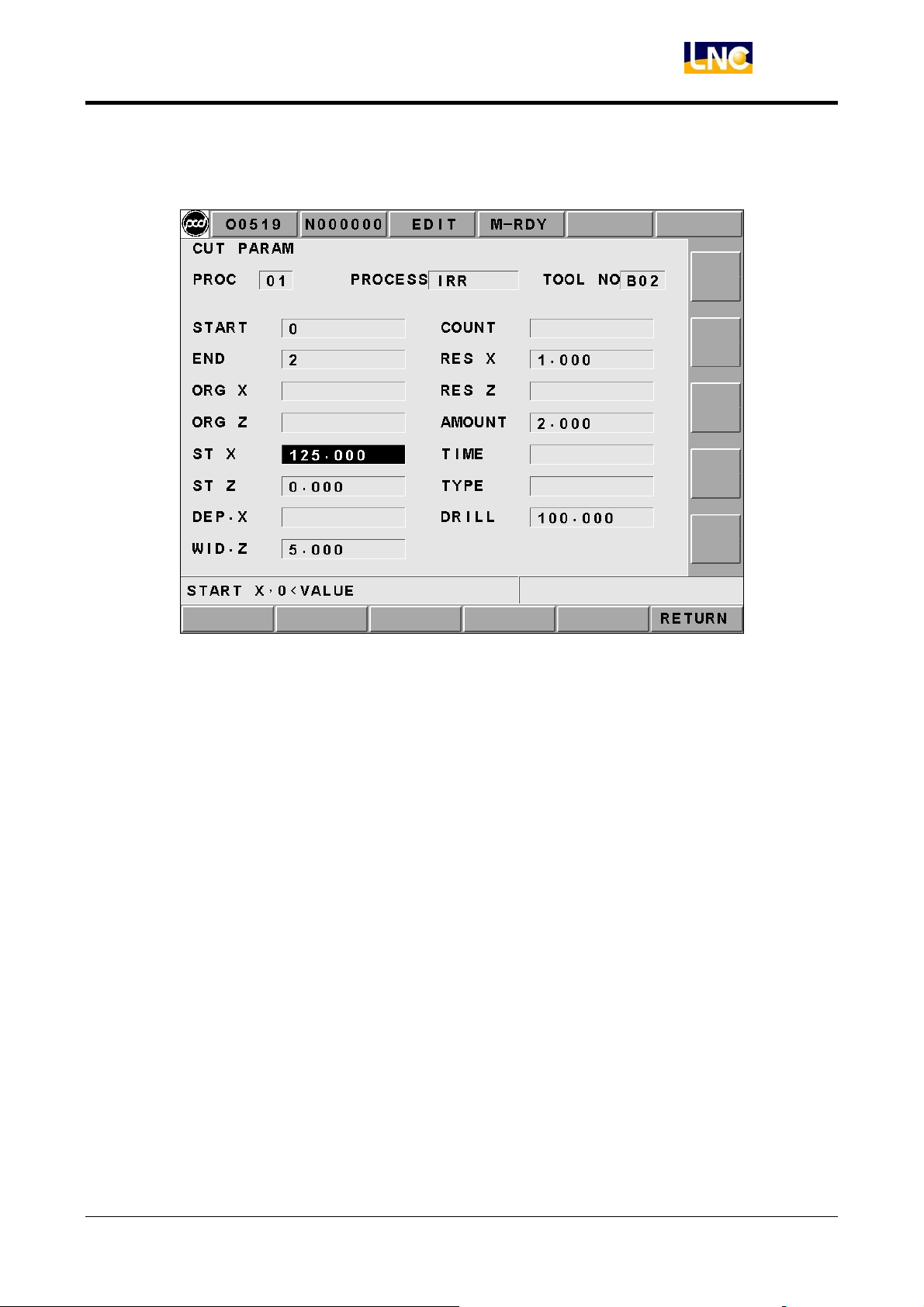
◎ Cutting Parameter is as the below screen:
LNC T520i
CNC Operation
Figure 2.6-8 Cutting Parameter Page
【Column Description】
※ Procedure:Display the currently editing procedure order number.
※ Working Method:Display the working name of the currently editing procedure.
※ Tool NO.:Display the selected tool NO. of the currently editing procedure. 4 types of
tool NO. Type A for drilling tool, Type B for pattern tool, Type C for grooving tool, and
Type D for thread tool. The number should be the tool NO. from the tool clear list of the
screen.
※ Cutting Parameter Column:The needed key-in column will be difference due to
different working methods.
☉ START:0.
☉ END:All linear and arch numbers of profile.
☉ ORG X:0.
☉ ORG Z:0.
☉ ST X:Material at the upper right point is the diameter coordinate.
☉ ST Z:Material at the upper right point is the Z coordinate
☉ DEP. X:lathe cutting depth
LNC Technology Co., Ltd.
71
Page 76

LNC T520i
CNC Operation
☉ WID. Z:Lathe cutting width.
☉ COUNT: Lathe-cutting repetitive times.
☉ RES X:Lathe-cutting preservation amount.
☉ RES Z:0
☉ AMOUNT: Lathe-cutting escape amount.
☉ TIME: Drilling dwell time.
☉ TYPE: The lathe-cutting mode selection.
☉ DRILL: Pre-drilling of internal lathe-cutting.
【Function keys at Screen Bottom】
※ Return:Switch to the main function screen.
【Function Keys at Right of Screen】
None.
72 LNC Technology Co., Ltd.
Page 77
LNC T520i
CNC Operation
◎ Geometry Definition:Below is the description of geometry drilling, geometry outlining,
geometry grooving, and geometry thread.
◇ Screen of Geometry Drilling is as below:
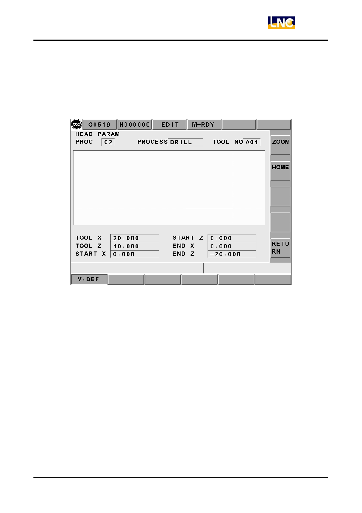
Figure 2.6-9 Geometry Drilling Page
【Column Description】
※ Procedure:Display the currently editing procedure order number.
※ Working Method:Display the selected tool NO. of the currently editing procedure. 4
types of tool NO. Type A for drilling tool, Type B for pattern tool, Type C for grooving
tool, and Type D for thread tool. The number should be the tool NO. from the tool clear
list of the screen.
※ Geometry Drilling Column:
☉ TOOL X:Tool point diameter coordinate
☉ TOOL Z:Tool point Z coordinate
☉ START X:Starting drilling hole point diameter coordinate, 0.
☉ START Z:Start drilling hole point Z coordinate.
☉ END X:Final drilling hole point diameter coordinate, 0.
☉ END Z:Final drilling hole point Z coordinate
LNC Technology Co., Ltd.
73
Page 78

LNC T520i
CNC Operation
【Function Keys at Screen Bottom】
※ Windows Scaling:Scale-in or return to original size of figure shape of display box at
center of screen.
※ Preview:Preview the Figure shape of the key-in data
※ Return:Switching screen to the main function screen.
【Function Keys at Right of Screen】
※ SCALE:Pressing the【SCALE】key at bottom of the screen for the “SCALE” key to
occur. Scale-in the selected Figure. A figure dialog box will occur when pressing this
key. Users are able to use 【UP】, 【DOWN】, 【LEFT】 and 【RIGHT】key to move
the dialog box. Moving the dialog box to the wanted scale-in position and pressing the
【ENTER】key to complete the action.
※ Fittest Size:Pressing 【WINDOW】at screen bottom for this function to be occur. This
will return to the original size of the Figure shape at inside of the dialog box at screen
center.
※ Return:Pressing the【SCALE】key at bottom of the screen to switch to the geometry
drilling screen.
74 LNC Technology Co., Ltd.
Page 79
◇ Screen of Geometry Profile is as below:
LNC T520i
CNC Operation
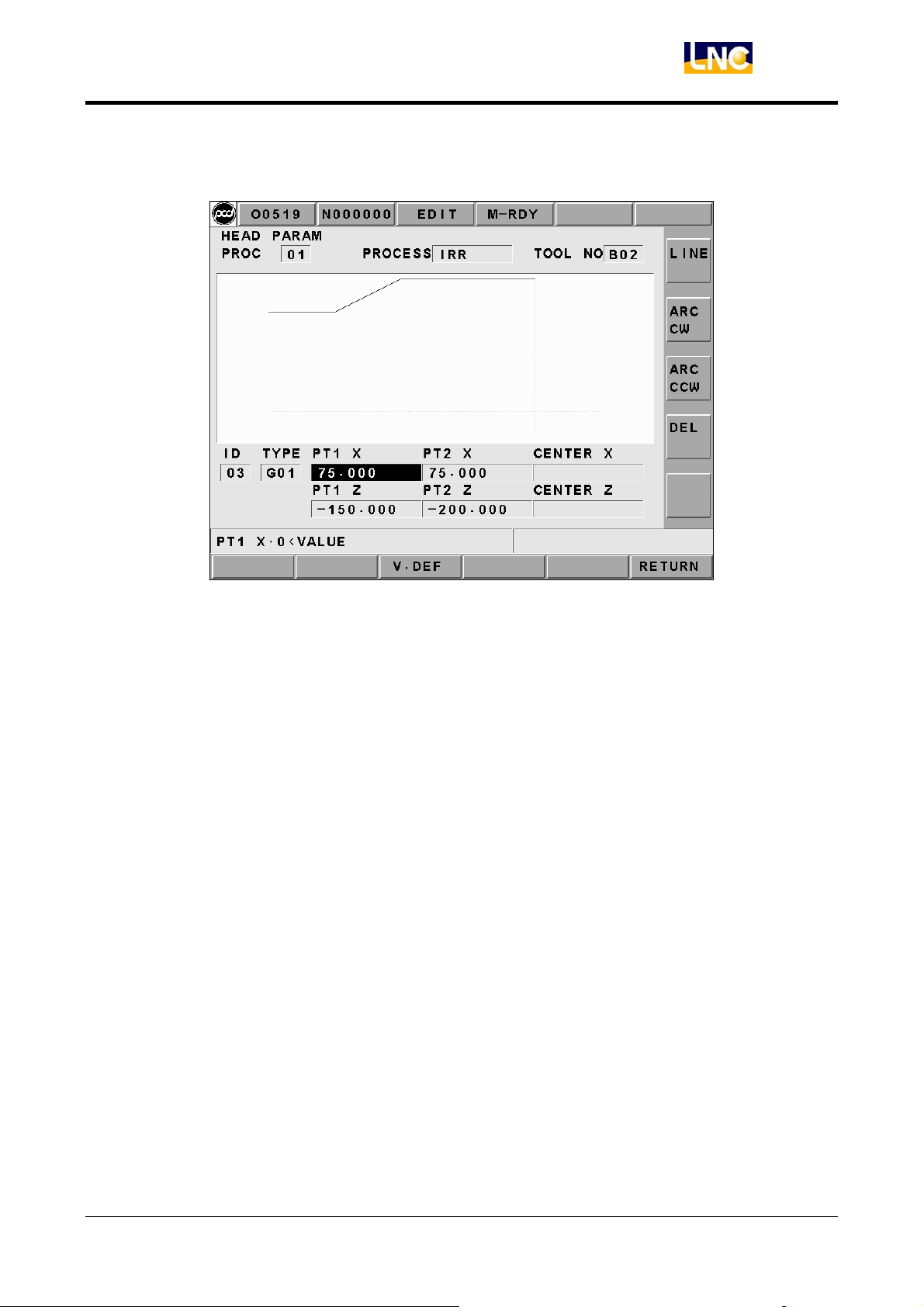
Figure 2.6-10 Geometry Profile Page
【Column Description】
※ Procedure:display the currently editing procedure order number
※ Working Method:display working name of the currently editing program
※ Tool NO.:display the selected tool NO. of the currently editing procedure. 4 types of
tool NO. Type A for drilling tool, Type B for pattern tool, Type C for grooving tool, and
Type D for thread tool. The number should be the tool NO. from the tool clear list of the
screen.
※ Order #:display profile linear order number, the system will auto-edit number.
※ Type : display profile linear type, G01 is linear, G02 is clockwise, and G03 is
counter-clockwise.
※ Geometry Profile Column:key-in the final-point coordinate of linear; cycle needs to
key-in multiple center-point coordinate.
☉ PT1 X:starting point diameter coordinate.
☉ PT1 Z:starting point Z coordinate.
☉ PT2 X:final point diameter coordinate.
☉ PT2 Z:final point Z coordinate.
☉ CENTER X:circle center diameter coordinate.
☉ CENTER Z:circle center Z coordinate.
LNC Technology Co., Ltd.
75
Page 80

LNC T520i
CNC Operation
【Function Keys at Screen Bottom】
※ Windows scale-in:scale-in or return to original size of the Figure shape of the dialog
box at screen center.
※ Return:switch to the main function screen.
※ Confirm:pressing 【LINE】 or 【CW】 or 【CCW】key at right of the screen to display
key-in data in Figure form and to display the confirm dialog box at the center of the
screen.
※ Cancel:pressing 【LINE】 or 【CW】 or 【CCW】key at right of the screen to cancel
key-in linear motion.
【Function Keys at Right of Screen】
※ Line:adding a new line. Users can key-in data after pressing this key. After pressing
this key, users can key-in data. Then, pressing 【OK】key at screen bottom to finish
adding new line.
※ CW:drawing a arch by clockwise direction. Users are able to key-in data after pressing
this key. Pressing【OK】key at screen bottom to complete this new adding action.
※ CCW:drawing a arch by counter clock-wise direction. Users are able to key-in data
after pressing this key. Pressing【OK】 key at screen bottom to complete this new
adding action.
※ Delete:delete the last line of the present profile
※ Zoom In:pressing the【SCALE】key at bottom of the screen for the “SCALE” key to
occur. Scale-in the selected Figure. A figure dialog box will occur when pressing this
key. Users are able to use 【UP】, 【DOWN】, 【LEFT】 and 【RIGHT】key to move
the dialog box. Moving the dialog box to the wanted zoom-in position and pressing the
【ENTER】key to complete the action.
※ Fittest Size:pressing 【WINDOW】at screen bottom for this function to be occur. This
will return to the original size of the Figure shape at inside of the dialog box at screen
center.
※ Return:when pressing【SCALE】 key at screen bottom to switch to the geometry
profile screen.
76 LNC Technology Co., Ltd.
Page 81
◇ Screen of Geometry Grooving is as below:
LNC T520i
CNC Operation
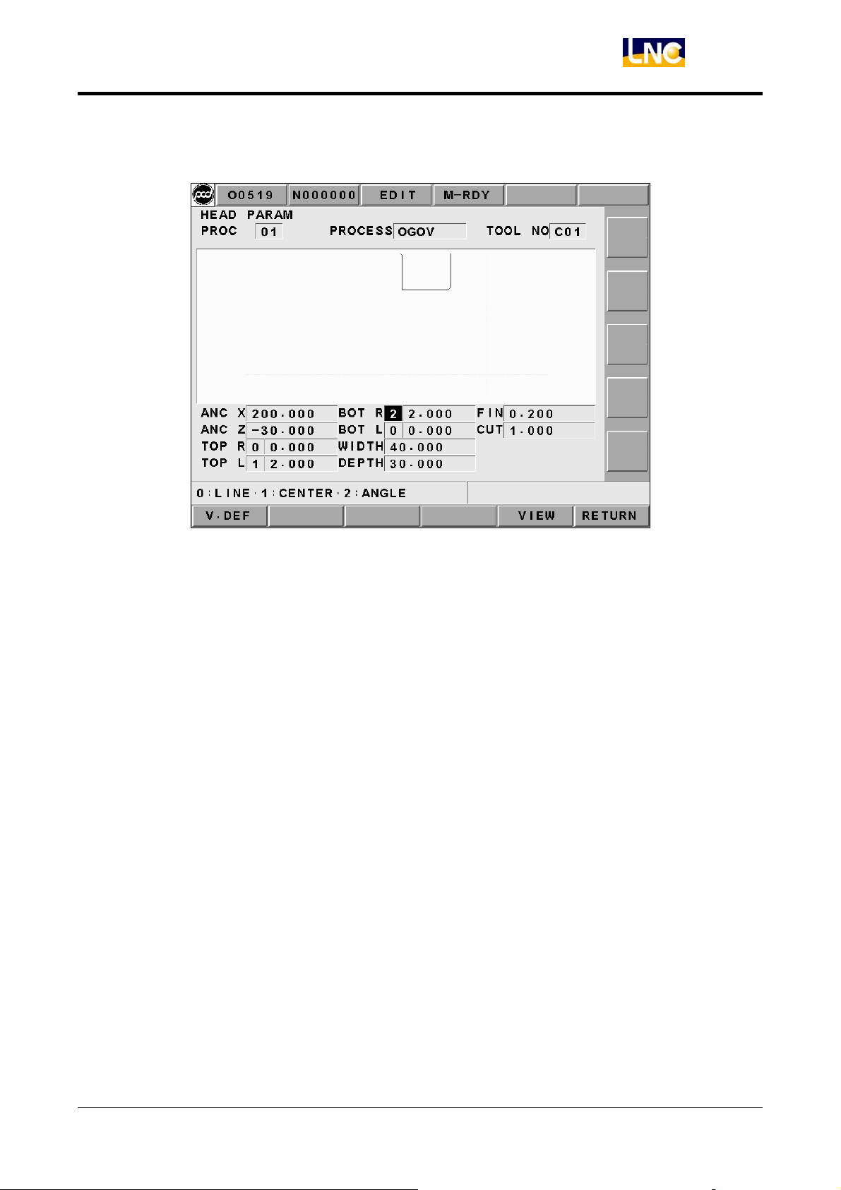
Figure 2.6-11 Geometry Grooving Page
【Column Description】
※ Procedure:display the currently procedure code number
※ Working Method:display the working name of the currently editing program.
※ Tool NO.:display the selected tool NO. of the currently editing procedure. 4 types of
tool NO. Type A for drilling tool, Type B for pattern tool, Type C for grooving tool, and
Type D for thread tool. The number should be the tool NO. from the tool clear list of the
screen.
※ Geometry Grooving Column:
☉ ANC X:Reference diameter coordinate.
☉ ANC Z:Reference Z coordinate.
☉ TOP R:upper right chamfer angle condition and amount, condition(0 = right angle,
1 = rounding angle, 2 = chamfer)but, the amount cannot be smaller than the
grooving-tool’s tool noise radius.
☉ TOP L:upper left chamfer angle condition and amount, condition(0 = right angle, 1=
rounding angle, 2 = chamfer ) but, the amount cannot be smaller than the
grooving-tool’s tool noise radius.
☉ BOT R:lower right chamfer angle condition and amount, condition(0= right angle,
1= rounding angle, 2= chamfer)but, the amount cannot be smaller than the
LNC Technology Co., Ltd.
77
Page 82

LNC T520i
CNC Operation
grooving-tool’s tool noise radius.
☉ BOT L:lower left chamfer angle condition and amount, condition(0= right angle, 1=
rounding angle, 2 = chamfer ) but, the amount cannot be smaller than the
grooving-tool’s tool noise radius.
☉ WIDTH:Grooving width.
☉ DEPTH:Grooving depth.
☉ FIN:preservation amount when cutting.
☉ CUT:everytime’s cutting width.
【Function Keys at Screen Bottom】
※ Windows Scale:scale-in or return to original size of figure shape of display box at
center of screen.
※ Preview:preview the Figure shape of the key-in data
※ Return:switch back to the main function screen.
【Function Keys at Right of Screen】
※ Scale:pressing the 【SCALE】 key at bottom of the screen for the “Zoom In” key to
occur. Scale-in the selected Figure. A figure dialog box will occur when pressing this
key. Users are able to use 【UP】, 【DOWN】, 【LEFT】 and 【RIGHT】key to move
the dialog box. Moving the dialog box to the wanted zoom-in position and pressing the
【ENTER】key to complete the action.
※ Fittest Size:
pressing 【WINDOW】at screen bottom for this function to be occur. This
will return to the original size of the Figure shape at inside of the dialog box at screen
center.
※ Return:pressing【SCALE】key at screen bottom to switch the screen to the geometry
grooving screen.
78 LNC Technology Co., Ltd.
Page 83
◇ Screen of Geometry Thread is as below:
LNC T520i
CNC Operation
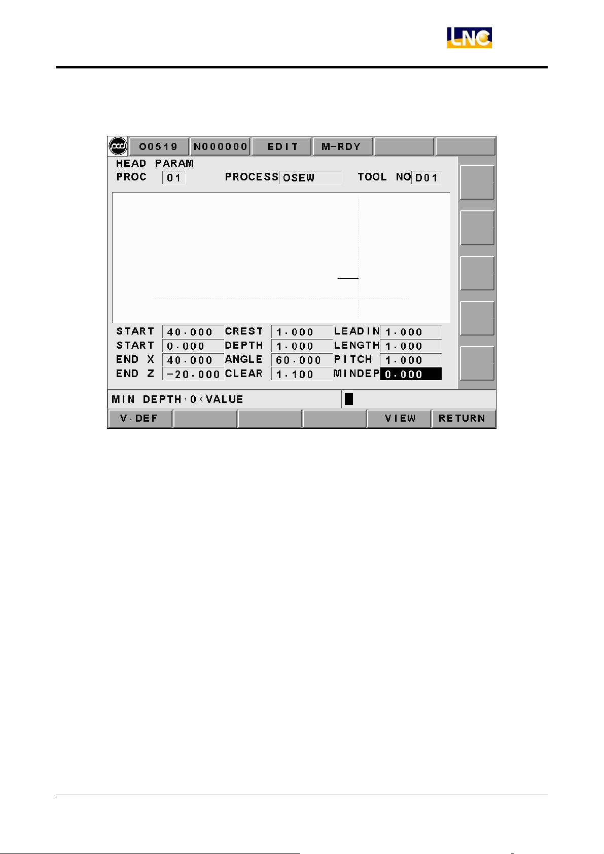
Figure 2.6-12 Geometry Thread Page
【Column Description】
※ Procedure:display the currently procedure code number.
※ Working Method:display the working name of the currently working programs.
※ Tool NO.:display the selected tool NO. of the currently editing procedure. 4 types of
tool NO. Type A for drilling tool, Type B for pattern tool, Type C for grooving tool, and
Type D for thread tool. The number should be the tool NO. from the tool clear list of the
screen.
※ Cutting Parameter Column:
☉ START:start tapping diameter coordinate
☉ START X:start tapping Z coordinate
☉ END:start tapping diameter coordinate
☉ END Z:end tapping Z coordinate
☉ CREST:thread height
☉ DEPTH:1
st
cutting depth
☉ ANGLE:tapping angle
LNC Technology Co., Ltd.
79
Page 84

LNC T520i
CNC Operation
☉ CLEAR:safety tool-hanging height
☉ LEADING:leading cutting amount
☉ LENGTH:post-chamfer angle length
☉ PITCH:tapping distance
☉ MINDEP:smallest lathe-cutting depth
【Function Keys at Screen Bottom】
※ Windows Scale:scale-in or return to original size of figure shape of display box at
center of screen.
※ Preview:preview the Figure shape of the key-in data
※ Return:switch to the main function screen.
【Function Keys at Right of Screen】
※ Scale:pressing the 【SCALE】 key at bottom of the screen for the “Zoom In” key to
occur. Scale-in the selected Figure. A figure dialog box will occur when pressing this
key. Users are able to use 【UP】, 【DOWN】, 【LEFT】 and 【RIGHT】key to move
the dialog box. Moving the dialog box to the wanted zoom-in position and pressing the
【ENTER】key to complete the action.
※ Fittest Size:pressing 【WINDOW】at screen bottom for this function to be occur. This
will return to the original size of the Figure shape at inside of the dialog box at screen
center.
※ Return:pressing【SCALE】key at screen bottom to switch the screen to the geometry
thread screen.
80 LNC Technology Co., Ltd.
Page 85
LNC T520i
CNC Operation
NOTE
※ Each parameter content will be different due to different working methods.
※ When a certain working part has set a geometry parameter, changeable types of
working methods of this procedure will be limited into the same working method. Using
“grooving on outer surfaces” as an example. Selecting “Procedure 1” as the “grooving
on outer surfaces” working method and setting the geometry variable.At this time, if
moving the highlighter to the working method selection, users can only choose
“Grooving on Outer Surfaces”, “Grooving on Inter Surfaces” and “Grooving on End
Faces”. Please add a new procedure if want to change the working method. Using the
same example for other three main types working methods.
※ Pattern cutting line must be from right to left and cannot be intersect with each other.
The max. line sections are 10.
※ Thread lathe-cutting is not able to do facing-thread and variable-lead thread.
※ Dwell time of tapping cutting parameter of drilling lathe-cutting cannot be zero.
Appendix A(Error Code Description)
◎ Table 2-1 Run Time DGNOS Output & Warning Message(R)
MSG Code Description
0 Complete program executing
1 Not enough memory
2 Curve not block
3 Curve section over 20
4 Lathe-cutting procedure over 10
5 Total tool number over 50
6 Tool parameter setting not reasonable
7 Cutting parameter setting not reasonable
LNC Technology Co., Ltd.
8 Not able to open file
9 Diskette is full
81
Page 86
LNC T520i
CNC Operation
Error Code Message (MSG)
◎Table 2-2 Tool Error Code(T)
102 Tool number setting smaller than 0
102 Spindle CW/CCW setting error
103 Cutting angle setting error
104 Max. effective setting error of external lathe cutting
105 Max. effective setting error of internal lathe cutting
106 Internal lathe-cutting setting error
107 Grooving tool width setting error or smaller than 0
108 Tool type setting error
109 Tool setting over 50 sets
110 Open file failure
◎ Table 2-3 Exchange File Error Code(E)
Error Code Message
121 Production number over range
122 G-code output type setting error
123 Diameter/radius program output setting error
124 Production tool number code assign error
125 Max. rotational speed assigning error
126 Assigned G94G95 setting error
127 No fixed value at G94 position
128 No fixed value at G95 position
129 Assigned G96G97setting error
130 No fixed value at G96 position
131 No fixed value at G97 position
132 Tool offset code smaller than 0
133 No assigned tool data in tool magazine
134 Production define error
135 Grooving profile definition (grooving width setting is less than 0)
136 Grooving profile definition(grooving setting value is less then 0)
82 LNC Technology Co., Ltd.
Page 87

Error Code Message
137 Grooving profile definition(preservation is less than 0)
138 Grooving profile definition(max. cutting width is less than 0 )
139 Grooving profile definition(grooving define error)
140 Thread profile definition (tapping height setting is less than 0)
141 1st time cutting depth setting error
142 Tapping angle setting error
143 Safety height is lower than tapping height
144 Leading cutting value is smaller than 0
145 Tapping distance setting error or smaller than 0
146 Min. cutting depth setting error
LNC T520i
CNC Operation
147 Thread type setting error
148 Profile lathe-cutting define(G01,G02.G03 assign error)
149 G02G03 define point can’t be arch
150 Drilling lathe-cutting parameter(drilling type selection error)
151 Drilling lathe-cutting parameter(feed amount setting error)
152 Drilling lathe-cutting parameter(tool escape amount setting error)
153 Rigid tapping cutting parameter(feel amount setting error)
154 Rigid tapping cutting parameter(tool escape setting error)
155 Rigid tapping cutting parameter(dwell time setting error)
156 Thread lathe-cutting parameter(feed type selection error)
157 Profile lathe-cutting parameter(stock removal type selection error)
158 Stock removal in facing (Material starting point setting error)
159 Stock removal in facing (Cutting width setting error)
160 Stock removal in facing (Preservation setting error )
161 Stock removal in facing (Tool escape amount setting error)
162 Stock removal in axis direction (Material starting point setting error)
163 Stock removal in axis direction (Cutting depth setting error)
164 Stock removal in axis direction (Preservation amount setting error)
165 Stock removal in axis direction (Tool escape amount setting error)
166 Stock removal in pattern (Material starting setting error)
167 Stock removal in pattern (Cutting depth setting error)
168 Stock removal in pattern (Preservation setting error)
LNC Technology Co., Ltd.
83
Page 88
LNC T520i
CNC Operation
Error Code Message
169 Stock removal in pattern (Tool escape amount setting error)
170 Stock removal in pattern (Cutting times setting error)
171 Profile lathe cutting line and arch numbers over limit
172 Opening file error
173 Tool corresponding turret NO. error
174 Material Z value setting error
175 Use external lathe-cutting tool error
176 Use internal lathe-cutting tool error
177 Use external grooving cutting tool error
178 Use internal grooving cutting tool error
179 Use face-grooving tool error
180 Use internal lathe-cutting tool error
181 Use external lathe-cutting tool error
182 Use drilling lathe-cutting tool error
84 LNC Technology Co., Ltd.
Page 89
LNC T520i
CNC Operation
2.7 GRAPH(GRAPH)
2.7.1 Function Introduction
Pressing function key【GRAPH】to enter into the【PROSIM】screen. This screen is able to
show the present working path or the working path of a preview program. Pressing
【CONSIM】to set the path display angle and the display range.
2.7.2 SIMU
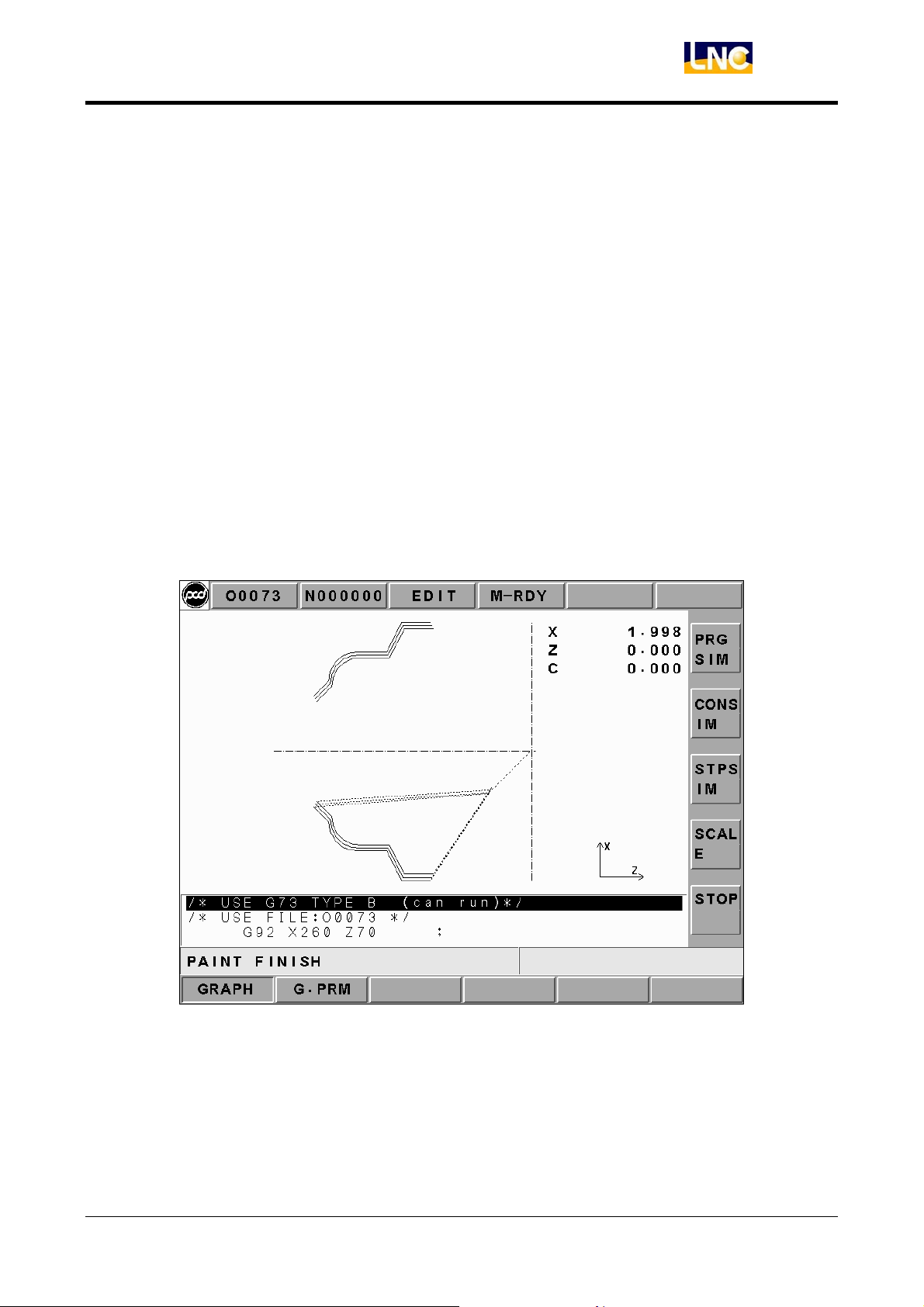
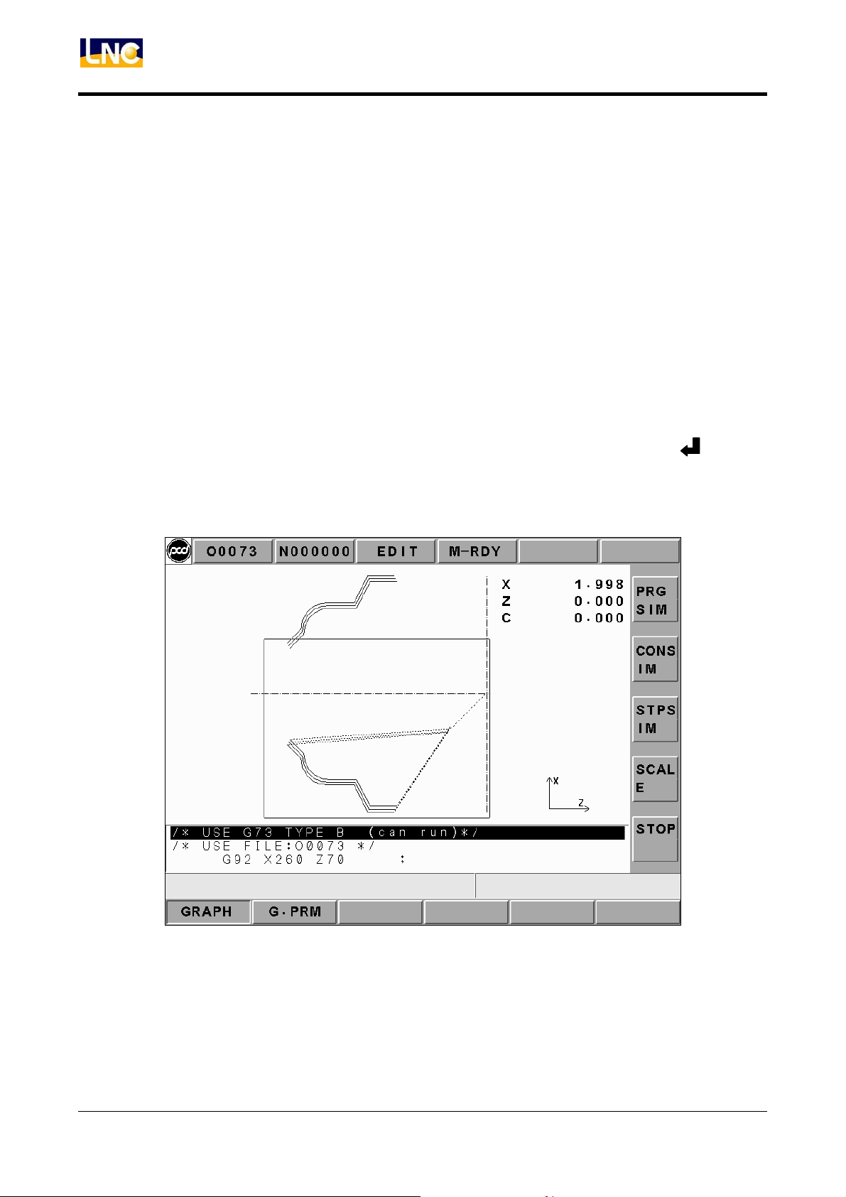
The path display screen is like the below Figure. Coordinate at upper right displays the
absolute coordinate of the present tool and lower right display the coordinate view angle.
Figure 2.7-1 Path Display Screen
【PRG SIM】:pressing this function key to draw the program setting’s working path in
program editing and CNC ready moods.
LNC Technology Co., Ltd.
85
Page 90
LNC T520i
CNC Operation
【CON SIM】:pressing this function key to draw the already restored program working
path again.
【STPSIM】:pressing this key to execute the single step drawing in order to draw the
downloaded program working path.
【STOP】:pressing this function key to stop the path drawing function when executing
【PRG SIM】or【CON SIM】.
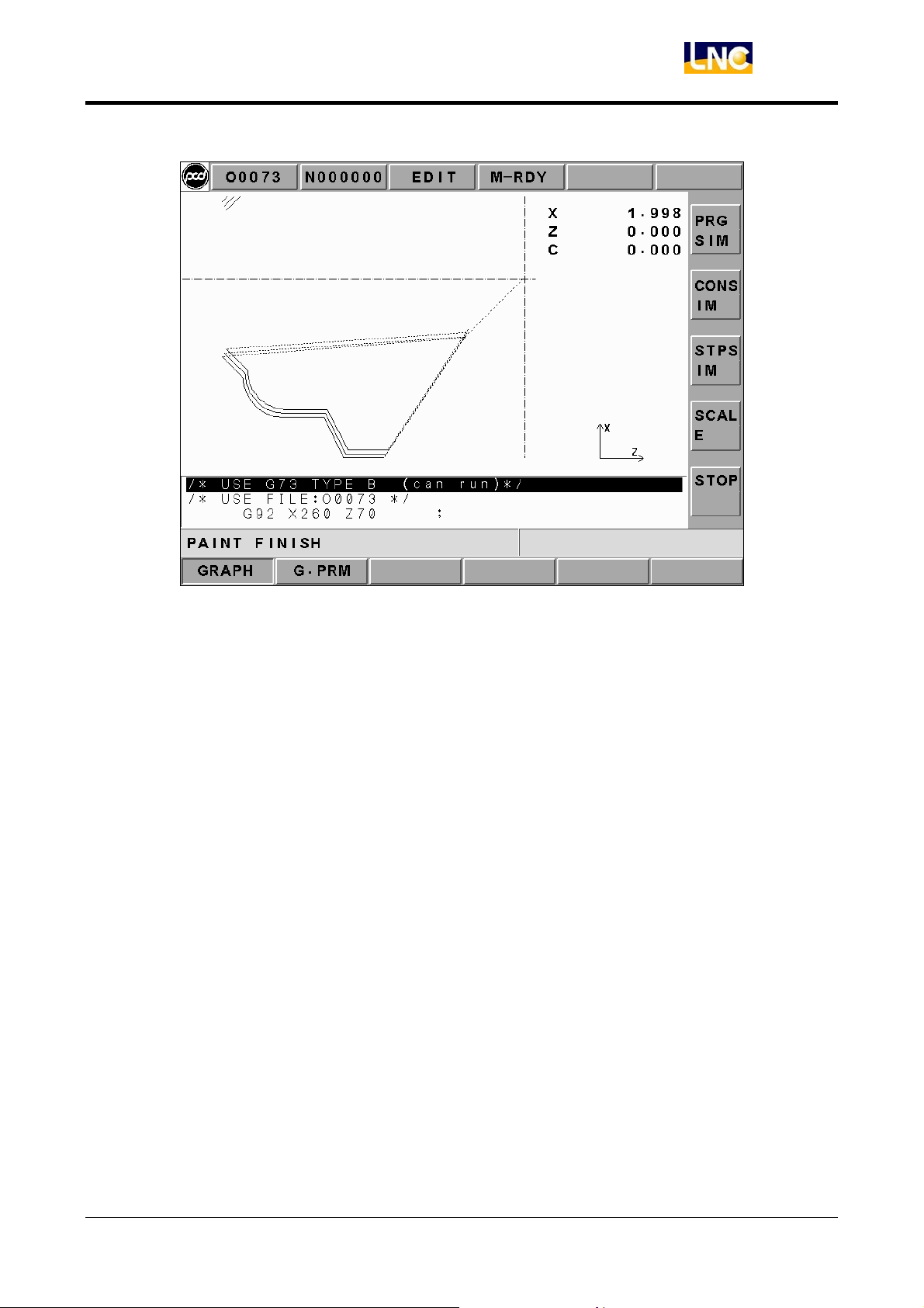
【SCALE】:a square border line will occur when pressing this function key, just like the
below Figure. This borderline indicates the zoom-in range of a Figure. Using
Page Up and Page Down keys to adjust the range size of the borderline.
Using direction key to move the borderline position. Pressing < > key or
【SCALE】 key to renew the working path inside the borderline when the
borderline has finished adjustment.
Figure 2.7-2 Before Figure Scale Out
86 LNC Technology Co., Ltd.
Page 91
LNC T520i
CNC Operation
Figure 2.7-3 After Figure Scale Out
※ Cursor is green when executing program, G00 is red, and G01, G02 and G03 are
yellow.
※ Cursor is green when program preview, G00 is blue, G01, G02 and G03 are pink. The
centerline is bright green.
LNC Technology Co., Ltd.
87
Page 92
LNC T520i
CNC Operation
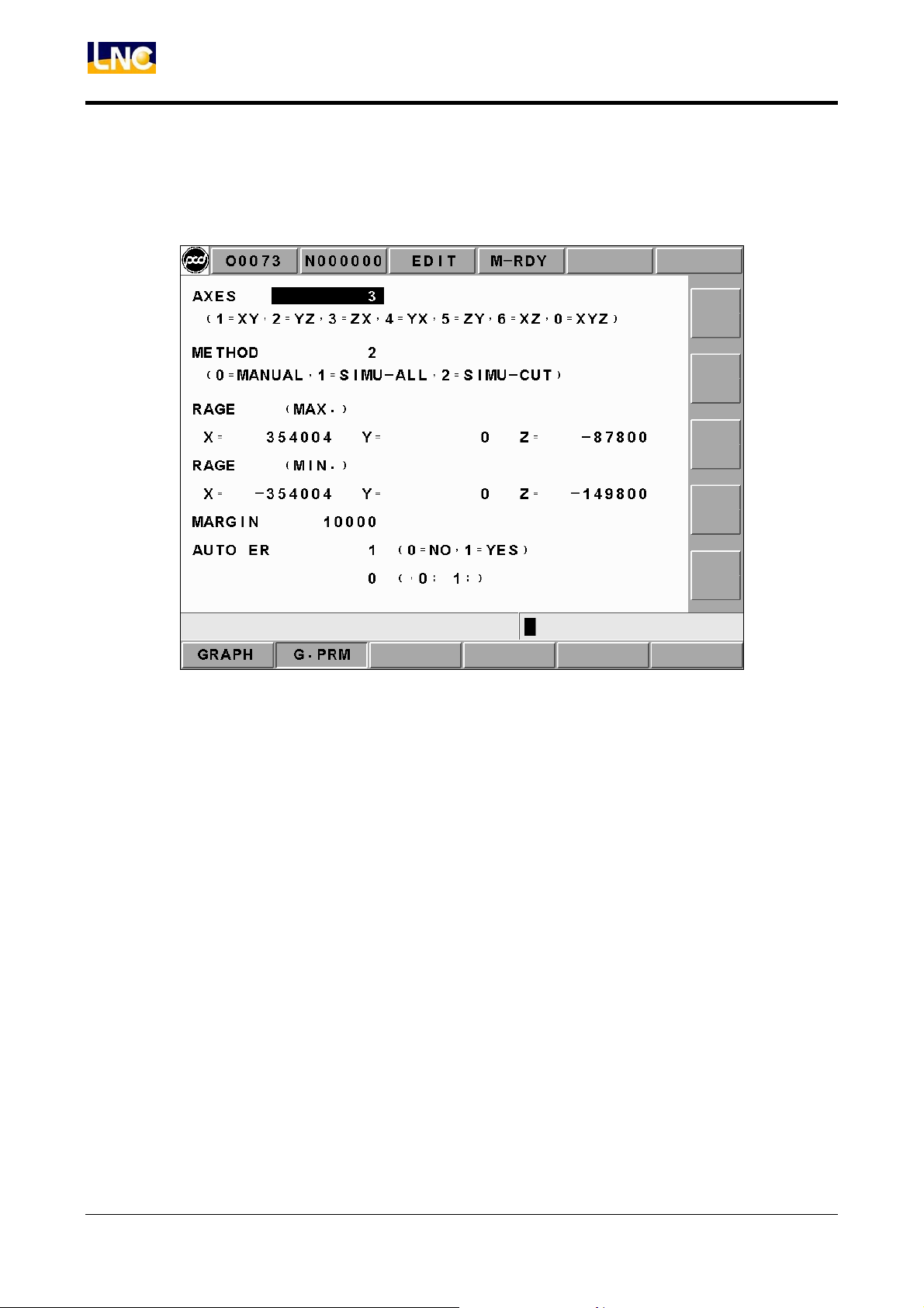
2.7.3 Window Definition
Figure 2.7-4 Screen of Window Definition
Drawing Panel:key-in the used coordinate view angle on the path display screen
(1=XY,2=YZ,3=ZX,4=YZ,5=ZY,6=XZ,0=XYZ).
Setting Method:key-in drawing range of【SIMU】screen(0=MPG,1=preview result
-full,2=preview result-cutting path).
0 MPG:preview the max. or min. value, set by manual, of the drawing range.
1 preview result-full:preview the drawing range as the max or min value of the
part program.
2 preview result-cutting path:preview the drawing range as the max and min
value of the cutting path of the currently reading program.
Drawing Range(max.):setting the max range of X, Y or Z axis range by manual
drawing.
Drawing Range(min.):setting the min. range of X, Y or Z axis range by manual
drawing.
88 LNC Technology Co., Ltd.
Page 93

LNC T520i
CNC Operation
Preserve Border:setting preservation amount for border in【SIMU】screen. Auto-Delete :
under the condition of not executing program preview and doing path display, users are
able to use this function to select whether or not to delete the previous path display screen
when enable cutting.(0=not delete, 1=auto delete).
LNC Technology Co., Ltd.
89
Page 94
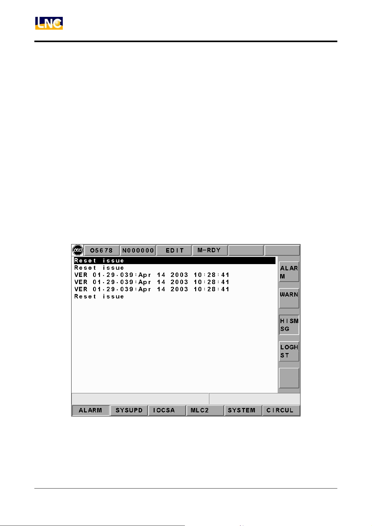
LNC T520i
CNC Operation
2.8 DGNOS
The following 6 main function screens, 【ALARM】, 【SYSUPD】, 【IOCSA】, 【MLC2】,
【SYSTEM】 and 【CIRCUL】 will occur by pressing <DGNOS> key. On DGNOS function
screen, users are able to know HMI and machine conditions in order to do the
maintenance and system testing.
2.8.1 ALARM
Pressing【ALARM】to enter into 【ALARM】, 【WARN】 and 【HISMSG】sub-functions
page. When any alarm or operation warning of MLC occurs, alarm or warning message
will occur on the screen. Users can use this screen to prevent any irregular condition of
controllers.
Figure 2.8-1 Alarm Content & Windows
90 LNC Technology Co., Ltd.
Page 95

LNC T520i
CNC Operation
【ALARM】
Alarm message will occur when there is any problem in system running. This will make the
system stop running and also will display the alarm message on the screen. When the
problem is solved, must press <RESET> in order to release the situation.
【WARN】
Warning message is decided by matching with the design of the MLC LADDER. Example
is when the safety door is not closed completely, LADDER program will send out “DOOR
NOT CLOSE” message. Or, when the Coolant Supply is broken, then the message
“COOLANT LAW” message will be sent out.
So when the alarm message occurs, please check the conditions of machine and
peripheral equipments according to the LADDER program. The system will stop running
when the system sends out the warning message and the warning message will be
displayed on the screen. When the problem is solved, must press <RESET> to release the
warning.
【HISMSG】
Able to display the version and program debug message after entering into the message
screen. Message displaying will not disconnect the working procedure, but it displays the
current running condition of the system.
LNC Technology Co., Ltd.
91
Page 96
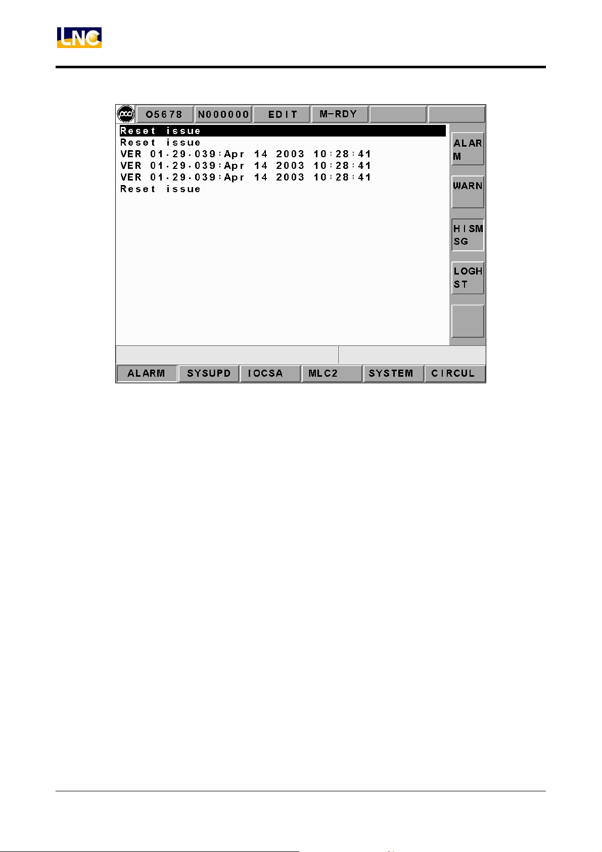
LNC T520i
CNC Operation
Figure 2.8-2 ALARM\ALARM
92 LNC Technology Co., Ltd.
Page 97
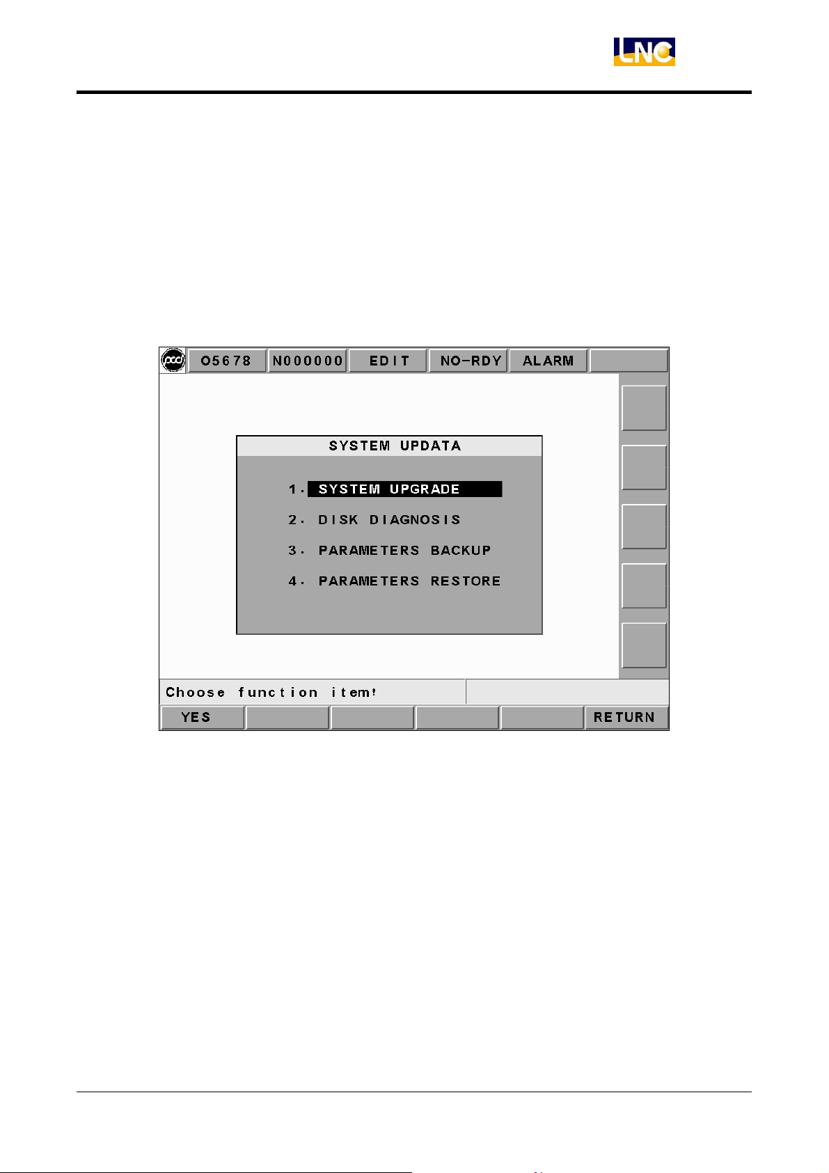
LNC T520i
CNC Operation
2.8.2 System Upgrade
This function can be executed only under the condition that CNC is NOT ready. Please
pressing 【UPDT】 button after pressing the EMG-STOP button. At this time, a screen
which function is selected by the cursor(Figure 2.10-3)will occur. This screen allows users
to select the wanted working item. Each function is listed as below:
LNC Technology Co., Ltd.
Figure 2.8-3 System Upgrade Screen
93
Page 98
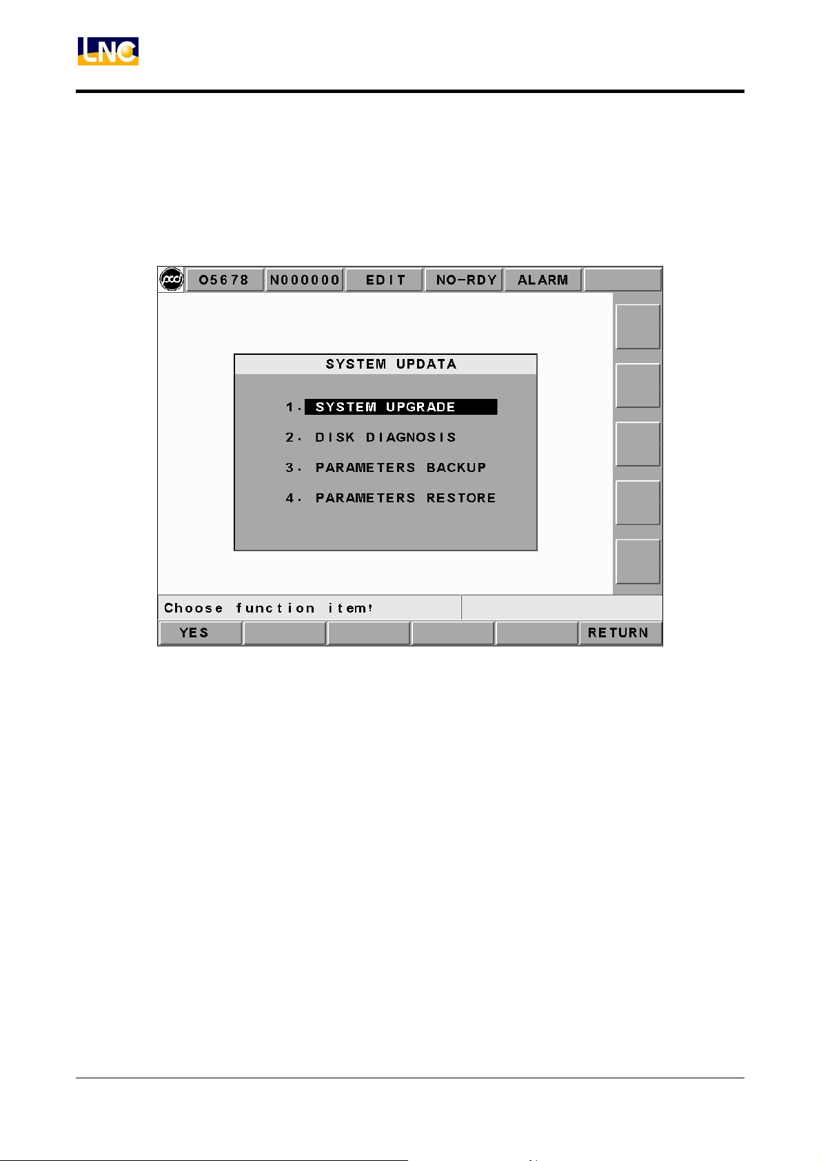
LNC T520i
CNC Operation
1. System Upgrade:
Please install Pou Yuen’s newest version software if choosing this function. Pressing
【YES】, the installation screen will occur. So, users only need to follow the instruction
to upgrade the system.
Figure 2.8-4 System Upgrade Screen
2. Disk Diagnosis:
Selecting this function, a confirmation dialog box will occur (like Figure 2.10-4).
Pressing the confirm button to return back to DOS mode (like Figure 2.10-5). Users are
able to choose to use A drive or C drive. If users do not choose, the system will use the
default C drive. There are 4 types of working items for users to choose:
(1)anti-virus,(2)hard drive scanning,(3)hard drive reset, and(4)exit
94 LNC Technology Co., Ltd.
Page 99
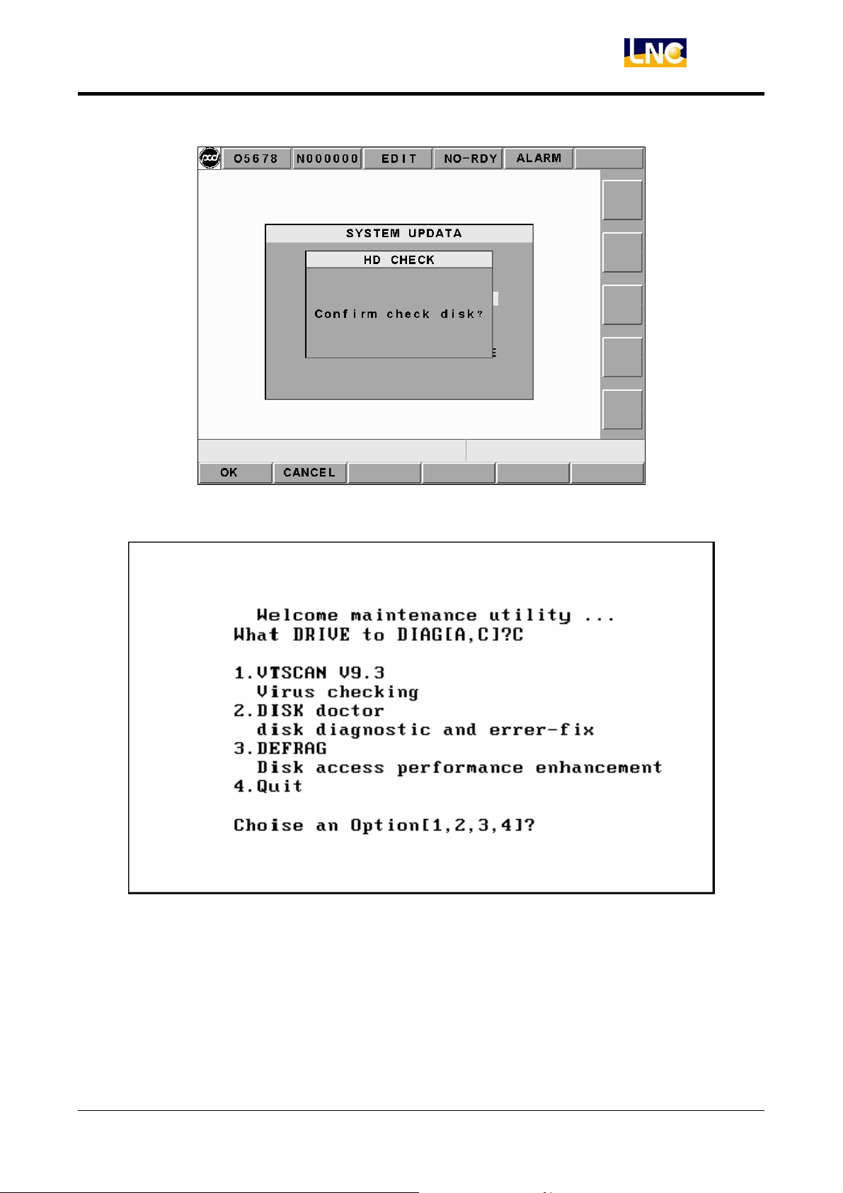
LNC T520i
CNC Operation
Figure 2.8-5 Confirm Whether or Not to Do the Hardware Checking
LNC Technology Co., Ltd.
Figure 2.8-6 Hardware Checking Function Selection
95
Page 100
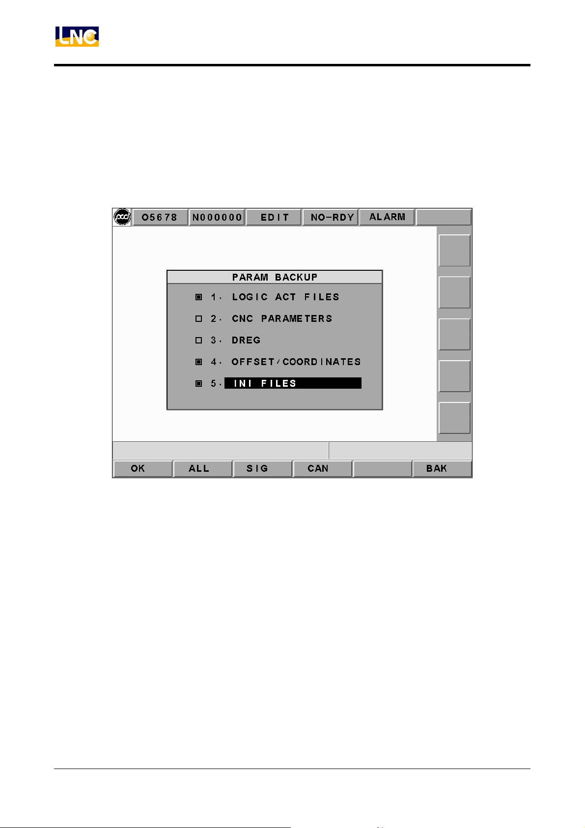
LNC T520i
CNC Operation
3. PARAM BACKUP (Parameter Backup)
The below dialog box will occur when choosing this function. Users are able to choose
the wanted backup parameter items. Users are able to key-in the dialog box of the
backup copy path after pressing the confirm button. Pressing the confirm button after
users key-in or select the wanted backup parameter to complete the parameter backup
function.
Figure 2.8-7 Parameter Backup Selection Screen
96 LNC Technology Co., Ltd.
 Loading...