


e/eM Style Standalone Keypad Installation/ Programming
Manual
This manual applies to these models: 212e, 212eM, 242e, and 242eM.
This equipment is designed to be installed and serviced by security and lock industry professionals.
Put Service Company Contact Information Here:
Company Name:
Service Number:
Contents
Section 1: |
Features and Product Description |
|
Section 2: |
Specifications |
|
Section 3: |
U.L. Requirements |
|
Section 4: |
Mounting |
|
Section 5: |
Wiring |
|
Section 6: |
Testing the Keypad |
|
Section 7: |
Programming |
|
Section 8: |
Troubleshooting |
|
Section 9: |
Programming Mode Loopback |
|
Section 10: |
Warranty |
|
Manual Revision Date: 12/10/04 |
Firmware Version: 1.0b |
|
Document # 6104401, Rev. 1.0, D1e |
1 |

e/eM Style Standalone Installation/Programming Manual
1. Features and Product
Description
1.1Features
•Flush Mount
•Indoor and Outdoor Use
•Keypad Programmable
•Access Control Functionality*
•Individually Control up to 4 Devices*
•Illuminated Backlit Keys (e keypad only)
•Durable Metal Braille Keys (eM keypad only)
•Keypress Feedback via Built-In Sounder
•Bi-Color Red/Green LED Indicates Relay Status
•Yellow LED Indicates Program Mode
•120 Users
•Panic and Duress Options
•Single Use Codes
•Lockout Users
•Two-Man Rule Option
•10 to 30 Volt DC Operation
•12 to 24 Volt AC Operation
•2 Amp Main Relay
•Remote Trigger Input (REX) *242 only
1.1.1Access Control Function (242 factory settings)
•Request to Exit Input
•Door Monitoring Input
•Relay Outputs
-Lock Release
-Forced Door
-Propped Door
-Alarm Shunt
•Keypad Programmable
2 |
Document # 6104401, Rev. 1.0, D1e |
e/eM Style Standalone Installation/Programming Manual
1.1.2 Output Functionality Options (242 field programmable settings)
•Request To Exit and Door Monitor Inputs
•Four Independently Programmable Outputs
•All Outputs Assignable by Code
•Outputs Programmable For Latched or Timed Operation
•Keypad Programmable
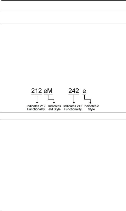
1.2Product Description and Naming Convention
IEI keypads and other standalone devices use an alpha-numeric model number convention to identify functionality and style. The numeric component identifies functionality. The alpha component identifies style.
Examples:
1.2.1 Functionality
The 242 keypad features the most flexibility and options available in a self-contained unit. It can perform access control functions, and also its four relay outputs can be assigned independently for timed operation or to latch. The 242 keypad can provide individual control of up to four devices, and is perfect for controlling electronic locking devices, security systems, CCTV systems, automatic operators, or machinery.
The 212 keypad features a single-relay output to control any device requiring an on/off switch. The output is timed or latched and operated by a user’s PIN code. Additionally, the 212 keypad provides basic keyless entry by controlling a door locking device where security is not an issue.
Document # 6104401, Rev. 1.0, D1e |
3 |

e/eM Style Standalone Installation/Programming Manual
1.2.2 Style
e keypads: Flush mount backlit keypad.
eM keypads: Flush mount durable metal keypad.
All keypads: Designed for both indoor and outdoor flush mount applications. The electronics for each keypad are conformal coated in the manufacturing process in order to provide this level of application flexibility. Installation is easy. All keypads mount to any standard single-gang electrical box or directly to any wall.
NOTE: This manual covers both 212 and 242 models. All features referring to the additional relays and outputs are available only on the 242 model.
4 |
Document # 6104401, Rev. 1.0, D1e |

e/eM Style Standalone Installation/Programming Manual
2. Specifications
Parameter |
Range/Description |
|||
Voltage |
10-30 VDC, 12-24 VAC (Auto-Adjusting) |
|||
|
e: |
|
|
|
|
75mA@10VDC, |
|
||
|
100mA@30VDC, |
|
||
Current |
125mA@12VAC, and |
|||
200mA@24VAC |
|
|||
|
eM: |
|
||
|
46mA@10VDC; 49mA@12VAC; |
|||
|
60mA@24VAC; 68mA@30VDC |
|||
|
Add 20 mA for each energized aux relay |
|||
Environment |
Indoor and Outdoor |
|||
Temperature Tolerance |
-20 °F to 130 °F (-28 °C to 54 °C) |
|||
Dimensions |
4.5" H x 2.75" W x 0.60" D |
|||
Main Relay (Form C) |
Contact Rating: |
2A @ 30VAC/DC |
||
Aux Relay (Form C) |
Contact Rating: |
1A @ 24V AC/DC |
||
REX Input |
Normally Open Dry Contact |
|||
Door Position Input |
Normally Closed Dry Contact |
|||
LEDs |
Bi-Color Red/Green Yellow |
|||
|
|
|
|
|
|
|
|
|
|
|
|
Default Settings |
||
Parameter |
|
|
Default Setting |
|
Master Code |
|
|
1234 |
|
Lock Output |
|
|
Relay 1 (Main Relay) (212 and 242) |
|
Alarm Shunt |
|
|
Relay 2 (242) |
|
Propped Door |
|
|
Relay 3 (242) |
|
Forced Door |
|
|
Relay 4 (242) |
|
Audio Alerts |
|
|
Not Assigned (212 and 242) |
|
REX |
|
|
Triggers Lock Output |
|
REX Operation |
|
|
Always Triggers (regardless of |
|
|
|
Door Loop) |
||
|
|
|
||
Error Lockout |
|
|
Enabled |
|
Error Lockout Threshold |
|
|
3 Attempts |
|
Error Lockout Duration |
|
|
10 Seconds |
|
Lock Output Time |
|
|
5 Seconds |
|
Propped Door Time |
|
|
30 Seconds |
|
Forced Door Time |
|
|
10 Seconds |
|
Visual Keypress Feedback |
|
Enabled |
||
Audio Keypress Feedback |
|
Enabled |
||
Auto-Entry |
|
|
Disabled |
|
User Lockout |
|
|
Enabled |
|
|
|
|
|
|
|
|
|
|
|
Document # 6104401, Rev. 1.0, D1e |
5 |

e/eM Style Standalone Installation/Programming Manual
3. U.L. Requirements
NOTE: This section applies to the 212e and 242e keypads only. The 212eM and 242eM keypads are not U.L. Listed.
The 212e/242e keypad is a U.L. Listed access control unit. This section contains information regarding all the requirements necessary to meet U.L. requirements.
This system must be installed in accordance with the National Electrical code (NFPA70), local codes, and the authorities having jurisdiction. In addition, all wires and cables used must be stranded and shielded U.L. Listed and/or recognized wire.
All interconnecting devices (that is, door contacts, REX, locking devices, etc.) must be U.L. Listed. A U.L. Listed access control power limited power supply must be used to power the keypad.
A minimum of three user codes must be programmed into the keypad for controlling access.
3.1 Tamper Requirements
To meet U.L. requirements, a U.L. Listed tamper switch must be installed in the single gang box used for mounting the keypad. The tamper switch must activate if the keypad is removed from the box and must disconnect power from the lock. The lock must be a failsecure device, meaning the lock remains locked when power is removed. In addition, once the tamper device is activated, it must be configured so that it can only be reset from within the protected area. Only a Sentrol 3012 or Sentrol 3025T tamper switch can be used. The diagrams on the next page show the suggested mounting location for each device.
6 |
Document # 6104401, Rev. 1.0, D1e |

e/eM Style Standalone Installation/Programming Manual
Figure 1 Mounting a Sentrol 3012 Tamper Switch
Figure 2 Mounting a Sentrol 3025T Tamper Switch
Document # 6104401, Rev. 1.0, D1e |
7 |
e/eM Style Standalone Installation/Programming Manual
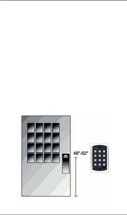
4. Mounting
The keypad is designed to be flush mounted using a standard sin- gle-gang electrical box. In addition, it can be flush mounted directly to the wall surface by cutting a hole in the wall. To properly size the mounting and wire access hole, use the installation template on the last page in this manual and on the unit’s container.
Mounting height can vary depending on requirements. An appropriate range is typically between 48 and 52 inches on center off the floor.
For outdoor installations, use a weatherproof backbox and seal the wire entry locations with silicone and provide a drain hole. In addition, use the anti-oxidant grease pack for the wire harness connectors.
Figure 3 Keypad Mounting Height
8 |
Document # 6104401, Rev. 1.0, D1e |

e/eM Style Standalone Installation/Programming Manual
5. Wiring
Figure 4 Keypad Connector and Wire Harness
5.1 Wire Harness Configuration
Pin |
Wire Color |
Signal Name |
|
|
|
|
|
1 |
Red |
V+ |
|
2 |
Black |
V- |
|
3 |
White/Black |
Not Used |
|
4 |
White/Yellow |
Not Used |
|
5 |
Brown |
Remote Trigger (REX) |
|
6 |
White/Orange |
Loop Common |
|
7 |
White |
Door Loop Monitor |
|
8 |
Green |
Main Relay - Normally |
|
Open |
|||
|
|
||
9 |
Blue |
Main Relay - Common |
|
10 |
Gray |
Main Relay - Normally |
|
Closed |
|||
|
|
||
|
|
|
NOTE: For wiring the accessory relay board, see sections 5.6 and 5.7.
Document # 6104401, Rev. 1.0, D1e |
9 |
 Loading...