


IEI 212e StandaloneTM
Keypad Installation/
Programming Manual
Contents
Section 1: Features and Product Description
1.1Features
1.2Product Description
Section 2: Specifications Section 3: Mounting Section 4: Wiring
4.1Wire Harness Configuration
4.2Wiring the 212e Keypad to a Maglock (Fail-Safe)
4.3Wiring the 212e Keypad to an Electric Strike (Fail-Secure)
4.4Shunting a Normally Closed Zone
4.5Wiring Remote Trigger as Request to Exit (REX) Button
Section 5: Testing the Keypad
Section 6: Programming
6.1Programming Main Relay Time
6.2Programming Users
6.3Programming Keypad Options
Section 7: Troubleshooting
Section 8: Programming Mode Loopback Section 9: Warranty
Document # 6104001, Rev. 1.0 |
1 |

IEI 212e Standalone Installation/Programming Manual
1. Features and Product
Description
1.1Features
•Flush Mount
•Indoor and Outdoor Use
•Keypad Programmable
•Illuminated Backlit Keys
•Keypress Feedback via Built-In Sounder
•Bi-Color Red/Green LED Indicates Relay Status
•Yellow LED Indicates Program Mode
•120 Users
•10 to 30 Volt DC Operation
•12 to 24 Volt AC Operation
•2 Amp Main Relay
•Remote Trigger Input (REX)
•5-Year Warranty
1.2Product Description
The 212e Keypad is designed for convenience, and features a single relay output to control any device requiring an on/off switch. The output is timed or latched and operated by a user’s PIN code. Additionally, the 212e Keypad can provide basic keyless entry by controlling a door locking device where security is not an issue. It allows 120 users as well as various keypad options.
All e style keypads are designed for both indoor and outdoor flush mount applications. The electronics for each e keypad are conformal coated in the manufacturing process in order to provide this level of application flexibility. In addition, each e style keypad uses hardened keys to assure long-term, high-quality performance. Each e style keypad contains illuminated clear keys that make operation in low-light situations easy and accurate. Installation is easy. All e style keypads mount to any standard single-gang electrical box or directly to any wall.
2 |
Document # 6104001, Rev. 1.0 |

IEI 212e Standalone Installation/Programming Manual
2. Specifications
Parameter |
Range/Description |
|
|
|
|
Voltage |
10-30 VDC, |
|
12-24 VAC |
|
|
|
|
|
|
|
|
|
65mA@12VDC, |
|
Current |
84mA@24VDC, |
|
50mA@12VAC, and |
|
|
|
|
|
|
80mA@24VAC |
|
|
|
|
Environment |
Indoor and Outdoor |
|
|
|
|
Temperature Tolerance |
-20 °F to 130 °F |
|
|
|
|
Dimensions |
4.5" H x 2.75" W x 0.60" D |
|
|
|
|
Main Relay (Form C) |
Contact Rating: |
2A @ |
|
30VAC/DC |
|
|
|
|
|
|
|
|
|
|
Document # 6104001, Rev. 1.0 |
3 |

IEI 212e Standalone Installation/Programming Manual
3. Mounting
The 212e Keypad is designed to be flush mounted using a standard single-gang electrical box. In addition, it can be flush mounted directly to the wall surface by cutting a hole in the wall. In order to properly size the mounting and wire access hole, use the installation template on the last page of this manual and on the unit’s container. Mounting height can vary depending on requirements. An appropriate range is typically between 48 and 52 inches on center off the floor.
For outdoor installations, use a weatherproof backbox and seal the wire entry locations with silicone. In addition, use the anti-oxidant grease pack for the wire harness connectors.
Figure 1 212e Mounting Height
4 |
Document # 6104001, Rev. 1.0 |
IEI 212e Standalone Installation/Programming Manual
4. Wiring
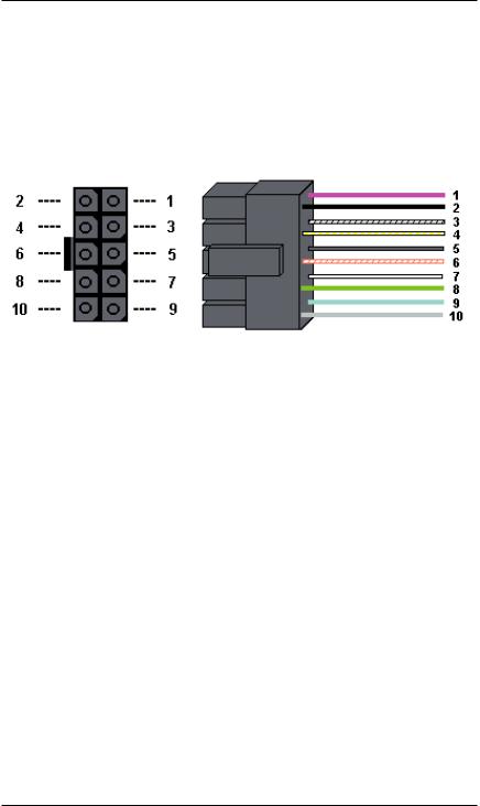
Figure 2 212e Connector and Wire Harness
4.1 Wire Harness Configuration
Pin |
Wire Color |
Signal Name |
|
|
|
|
|
1 |
Red |
V+ |
|
|
|
|
|
2 |
Black |
V- |
|
|
|
|
|
3 |
White/Black |
Not Used |
|
|
|
|
|
4 |
White/Yellow |
Not Used |
|
|
|
|
|
5 |
Brown |
Remote Trigger (REX) |
|
|
|
|
|
6 |
White/Orange |
Loop Common |
|
|
|
|
|
7 |
White |
Not Used |
|
|
|
|
|
8 |
Green |
Main Relay - Normally |
|
Open |
|||
|
|
||
|
|
|
|
9 |
Blue |
Main Relay - Common |
|
|
|
|
|
10 |
Gray |
Main Relay - Normally |
|
Closed |
|||
|
|
||
|
|
|
|
|
|
|
Document # 6104001, Rev. 1.0 |
5 |
 Loading...