

Page 1
Installation
Instructions
For Fully Integrated Freezer
MF 1851 / MF 2451 / MF 3051 / MF 3651
7085 859-00
Page 2
I
mportant
Please Read and Follow these
Instructions
These instructions contain Danger, Warning and
Caution notes.
This information is important for safe and efficient
installation and operation.
Always read and comply with all Danger, Warning and
Caution notes!
DANGER!
Danger indicates a hazard which
will cause serious injury or death if
precautions are not followed.
WARNING !
Warning indicates a potentially hazardous
situation which, if not avoided, could result
in death or serious injury.
CAUTION!
Caution indicates a potentially hazardous
situation which, if not avoided, may result
in minor or moderate injury.
IMPORTANT
This indicates information that is especially relevant
to a problem-free installation and operation.
Content Page
Please Read and Follow these Instructions.................. 2
Note to the Installer ........................................................ 2
R600a Refrigerant ......................................................... 2
Disposal of Old Appliance ............................................. 3
Disposal of Packaging Material ..................................... 3
Electrical Safety ............................................................. 3
Blocking for Safety ......................................................... 3
Appliance Dimensions ................................................... 4
Door Swing Clearance (top view) ................................. 5
Cabinet Opening Dimensions ....................................... 6
Panel Dimensions .......................................................... 8
Unpacking .....................................................................10
Standard Accessories...................................................12
Mounting the anti tipping device in cabinets deeper
than 24" - Figure 1- 2 ...................................................13
Mounting the anti tipping device on wooden floors -
Figure 3 .........................................................................13
Mounting the anti tipping device on concrete floors -
Figure 4 - 5 ....................................................................14
Safety Instructions and Warnings for Water Connection ..15
Water Connection Requirements .................................15
Appliance Installation ....................................................15
Please note in case of removing appliance from the
recess ........................................................................... 24
Important Note for Changing over Door Hinges or
Limiting the Hinges to a 90° Opening Angle .............. 24
R600a Refrigerant
Note to the Installer
It is very important to follow the instructions in the
manual to ensure proper installation and operation of
the unit.
Before installing the unit, be sure to thoroughly read
and understand all of the information in this manual.
WARNING !
Electrocution hazard.
Do not connect to the electrical outlet
before the installation is completed.
2
WARNING !
The refrigerant R600a contained within the
appliance is environmentally friendly, but
flammable. Leaking refrigerant can ignite.
To prevent possible ignition, follow
the warnings below:
•
Keep ventilation openings, in
the appliance enclosure or in
the built-in structure, clear of
obstruction.
• Do not damage the refrigerant
circuit.
• Component parts and power cords shall be
replaced with like components performed by
factory authorized service personnel only.
Page 3
S
afety
Disposal of Old Appliance
DANGER!
Risk of child entrapment.
Child entrapment and suffocation are not problems of
the past.
Junked or abandoned refrigerators are still dangerous –
even if they will sit for “just a few days.”
If you are getting rid of your old refrigerator, please follow these instructions to help prevent accidents.
Before you discard old appliances:
• Take off the doors.
• Leave the shelves in place so that children
may not easily climb inside.
• Cut off the power cable from the discarded
refrigerator. Discard separately from the
refrigerator.
• Be sure to follow your local requirements for
disposal of appliances.
Electrical Safety
Connect this appliance to a 15 amp or 20 amp, 110120 VAC circuit which is grounded and protected by a
circuit breaker or fuse.
We recommend using a dedicated circuit for this appliance to prevent circuit overload and the chance of
interruption to the appliance.
This appliance is equipped with a three-prong (grounding) polarized plug for your protection against possible
shock hazards.
Where a two-prong wall receptacle is encountered,
contact a qualified electrician and have it replaced with
a properly grounded three-prong receptacle in accordance with all local codes and ordinances.
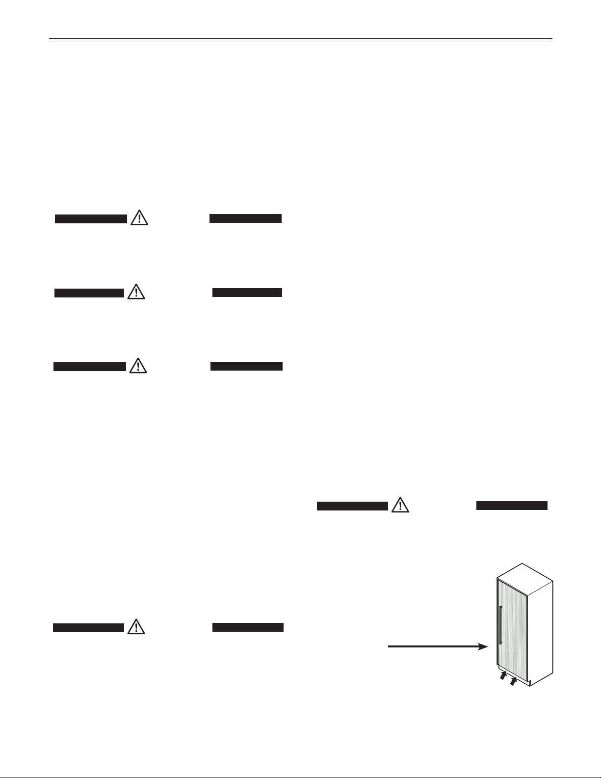
WARNING!
Electrocution hazard.
Electrical grounding required.
Do not remove the round grounding
•
prong from the plug.
Contact the trash collection agency in
your area for additional information.
Disposal of Packaging Material
WARNING !
Keep packaging materials away from
children. Polythene sheets and bags can
cause suffocation!
If possible, please recycle packaging material at a recycling facility.
Do not use extension cords or
•
ungrounded (two prong) adapters.
• Do not use a power cord that is frayed or
damaged.
• Do not use a power strip.
Failure to follow these instructions may
result in fire, electric shock or death.
Blocking for Safety
WARNING !
To avoid a hazard due to instability of the
appliance, it must be fixed in accordance
with the instructions.
3
Page 4
p
lannIng
I
nformatIon
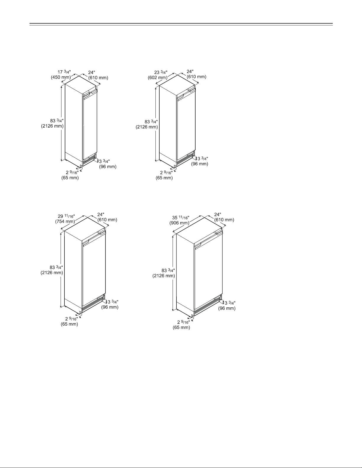
Appliance Dimensions
MF 1851
MF 2451
MF 3651MF 3051
Stated minimum height dimensions include when the levelled feet are fully inserted.
Width will increase by 1/4" (6.5 mm) when mounting strips are installed.
4
Page 5
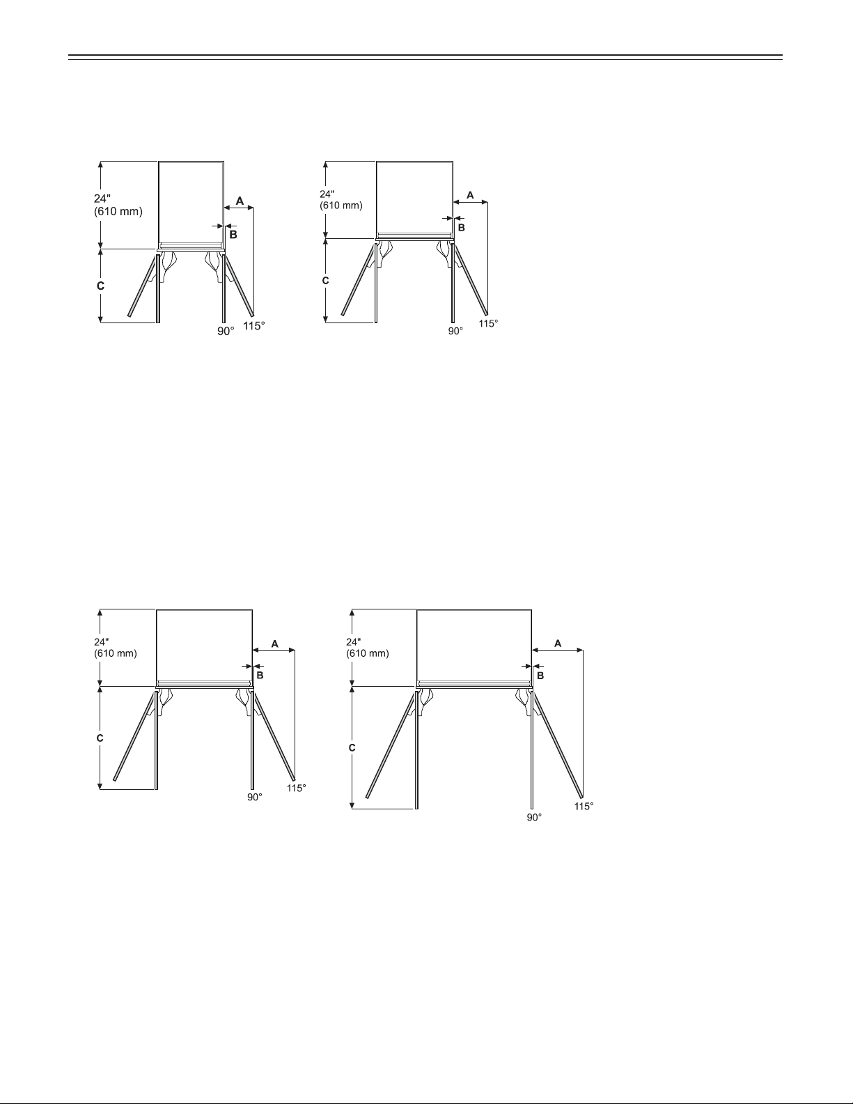
Door Swing Clearance (top view)
p
lannIng
I
nformatIon
MF 1851
Inset installation style
A = 8 1/4" (210 mm)
B = 1/2" (12.5 mm)
C = 19 7/8" (505 mm)
Frameless installation style
A = 8 1/2" (216 mm)
B = 1/2" (12.5 mm)
C = 20 3/8" (517 mm)
MF 2451
Inset installation style
A = 10 3/4" (273 mm)
B = 1/2" (12.5 mm)
C = 25 7/8" (658 mm)
Frameless installation style
A = 11" (279 mm)
B = 1/2" (12.5 mm)
C = 26 3/8" (670 mm)
MF 3051 MF 3651
Inset installation style
A = 13 1/4" (337 mm)
B = 1/2" (12.5 mm)
C = 31 7/8" (810 mm)
Frameless installation style
A = 13 1/2" (343 mm)
B = 1/2" (12.5 mm)
C = 32 3/8" (822 mm)
Inset installation style
A = 15 3/4" (400 mm)
B = 1/2" (12.5 mm)
C = 37 7/8" (962 mm)
Frameless installation style
A = 16" (406 mm)
B = 1/2" (12.5 mm)
C = 38 3/8" (975 mm)
Dimension A and B: Add panel thickness and handle to calculate distance to wall.
5
Page 6
p
lannIng
I
nformatIon
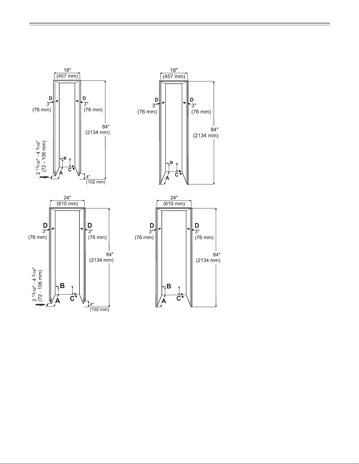
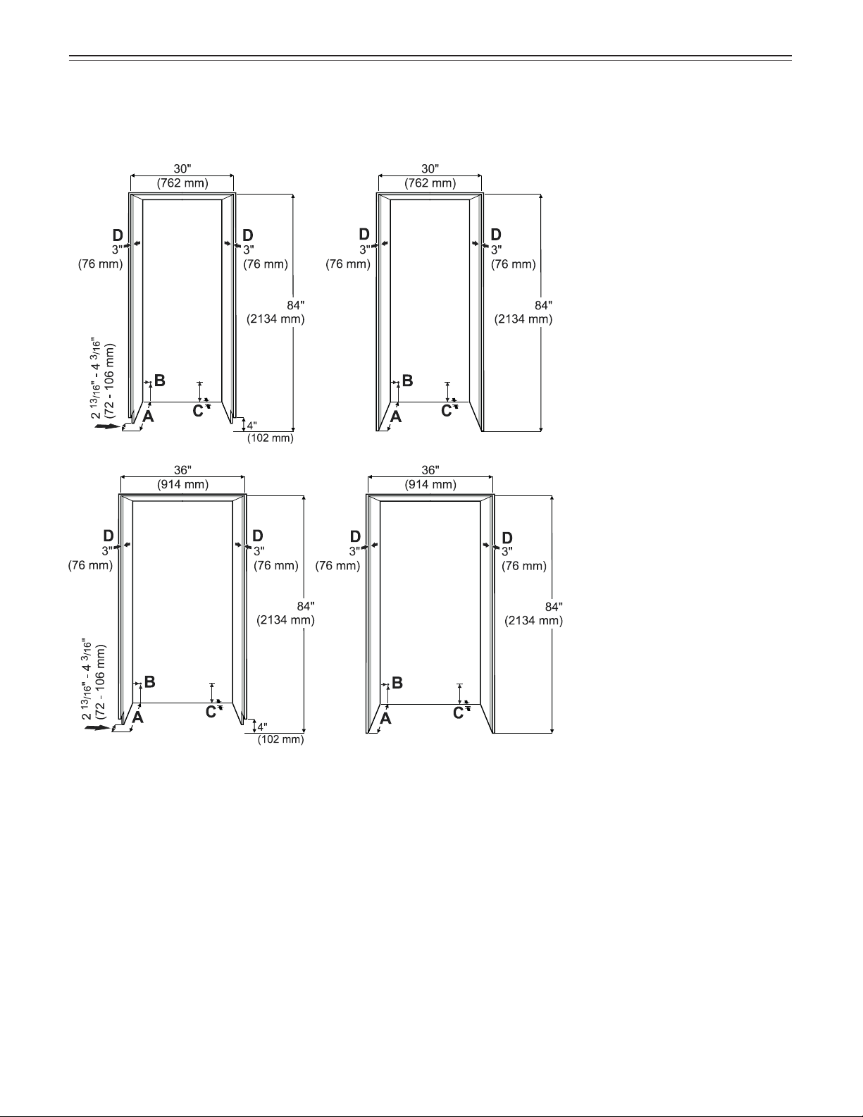
Cabinet Opening Dimensions
Continous toe kick Individual toe kick
A
Cabinet depth frameless installation
style = 25" (635 mm)
Cabinet depth inset installation
style = 25" (635 mm) plus panel
thickness
B
This is the point where the power
cord exits from the appliance rear.
3/4" (19 mm) from the left and 5"
(127 mm) from the floor.
Free length of the power cord is 98"
(2.5 m).
IMPORTANT
The power plug must be
easily accessible so that
the appliance can be
disconnected from the mains
quickly in an emergency. It
must not be behind the back
of the appliance.
C
The appliance has a recess in this
area for cable and waterline laying.
1" (25 mm) in depth and 5 1/2"
(140 mm) in height over the whole
width of the appliance.
D
This surface is visible when the
appliance door is open. Designed
finish is required.
6
Page 7
p
lannIng
Continous toe kick Individual toe kick
I
nformatIon
A
Cabinet depth frameless installation
style = 25" (635 mm)
Cabinet depth inset installation
style = 25" (635 mm) plus panel
thickness
B
This is the point where the power
cord exits from the appliance rear.
3/4" (19 mm) from the left and 5"
(127 mm) from the floor.
Free length of the power cord is 98"
(2.5 m).
IMPORTANT
The power plug must be
easily accessible so that
the appliance can be
disconnected from the mains
quickly in an emergency. It
must not be behind the back
of the appliance.
C
The appliance has a recess in this
area for cable and waterline laying.
1" (25 mm) in depth and 5 1/2"
(140 mm) in height over the whole
width of the appliance.
D
This surface is visible when the
appliance door is open. Designed
finish is required.
7
Page 8
p
lannIng
I
nformatIon
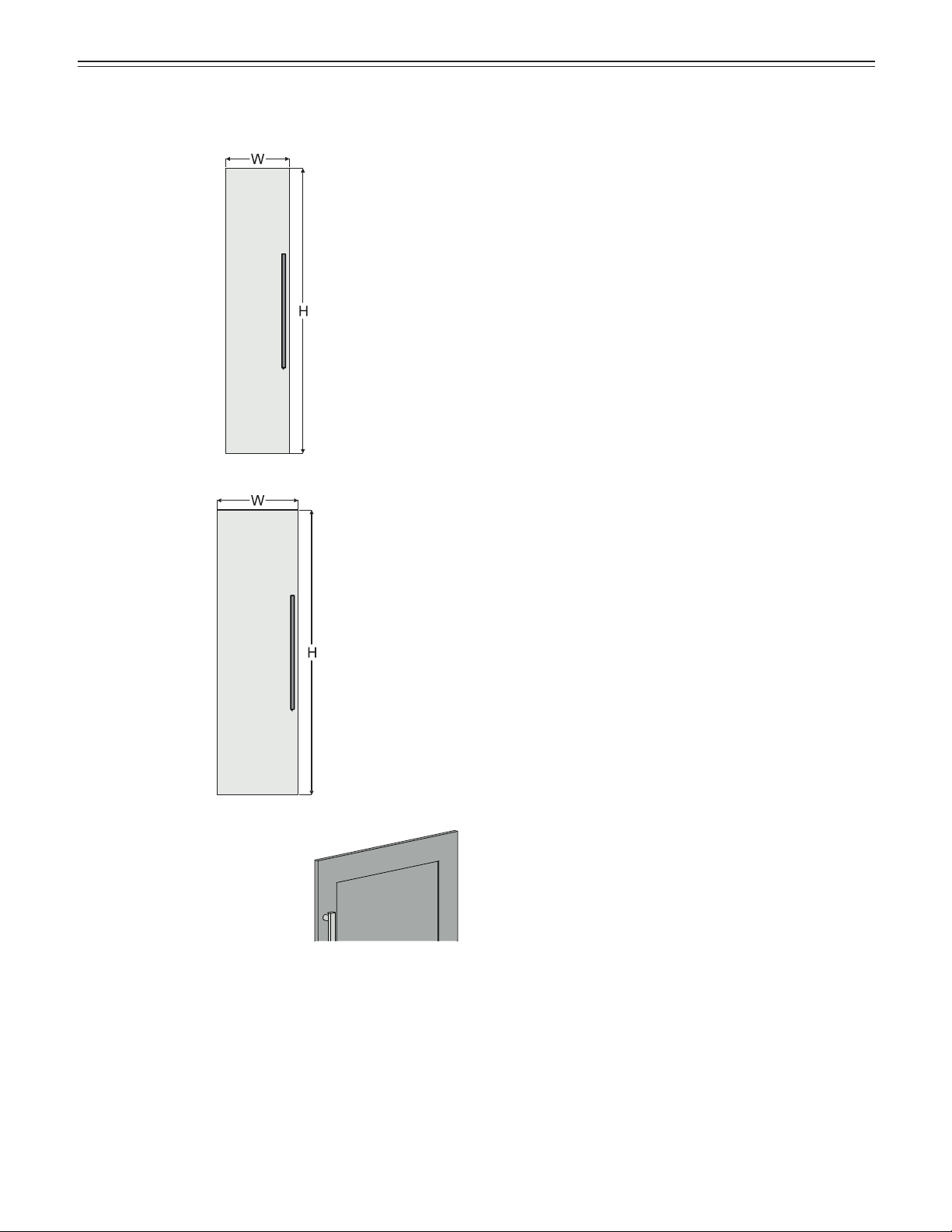
Panel Dimensions
18" recess
Inset installation style
H = 79 7/8" (2029 mm)
W = 17 3/4" (451 mm)
Frameless installation style
H = 80" (2032 mm) plus overlapping of the panel on the top
W = 18" (457 mm) plus overlapping of the panel on both sides
Minimum panel thickness = 5/8" (16 mm) *
Maximum panel thickness = 1" (25 mm)
Maximum panel weight = 55 lbs (25 kg)
24" recess
Inset installation style
H = 79 7/8" (2029 mm)
W = 23 3/4" (603 mm)
Frameless installation style
H = 80" (2032 mm) plus overlapping of the panel on the top
W = 24" (610 mm) plus overlapping of the panel on both sides
Minimum panel thickness = 5/8" (16 mm) *
Maximum panel thickness = 1" (25 mm)
Maximum panel weight = 66 lbs (30 kg)
* If a “shaker style” panel is used which undershoots
the minimum panel thickness, shorter screws than
those supplied in the accessory pack must be used.a
8
Page 9

p
lannIng
30" recess
Inset installation style
H = 79 7/8" (2029 mm)
W = 29 3/4" (756 mm)
Frameless installation style
H = 80" (2032 mm) plus overlapping of the panel on the top
W = 30" (762 mm) plus overlapping of the panel on both sides
Minimum panel thickness = 5/8" (16 mm) *
Maximum panel thickness = 1" (25 mm)
Maximum panel weight = 77 lbs (35 kg)
I
nformatIon
36" recess
Inset installation style
H = 79 7/8" (2029 mm)
W = 35 3/4" (908 mm)
Frameless installation style
H = 80" (2032 mm) plus overlapping of the panel on the top
W = 36" (914 mm) plus overlapping of the panel on both sides
Minimum panel thickness = 5/8" (16 mm) *
Maximum panel thickness = 1" (25 mm)
Maximum panel weight = 88 lbs (40 kg)
* If a “shaker style” panel is used which undershoots
the minimum panel thickness, shorter screws than
those supplied in the accessory pack must be used.a
9
Page 10

U
npackIng
Unpacking
1. Cut the straps and
remove them.
2. Press in the lug, tear
or cut the carton on
the edge and remove
it.
3. Remove all styrofoam packing
material from the sides and top.
4. Remove the box with
mounting parts.
Tx™ 2 0
Tx™ 2 0
7. Remove the safety transportation brackets and anti tipping
device.
Remove the packed cover
strips and support strips from
the appliance rear.
WARNING !
Risk of injury and damage.
5. Remove the ventilation grille.
6. Secure the appliance door with tape
to prevent it from being opened accidentally.
DANGER!
Risk of death or serious injury due to
appliance tipping.
Do not remove the transit supports before
the appliance is in the recess.
Four people are required to safely remove
the appliance from the bottom pallet.
8. One person tilt the appliance back
carefully and holds it in place.
9. Two people grasp the appliance from the bottom and
lift. One on each side.
10. One person removes the pallet.
Place the appliance carefully on the floor.
10
Page 11

U
npackIng
Alternative possibility:
Cut off the marked area from the pallet.
or
Tilt the appliance slightly sideways.
Slide a two-wheeled cart between the appliance and
packaging.
Restrain the appliance to the cart with straps.
Tilt the appliance onto the cart.
Place the appliance carefully on the floor.
11
Page 12

S
tandard
a
cceSSorIeS
Standard Accessories
Ventilation grille
Top cover for the door
panel attachment bracket
anti tipping device
Retaining screws for installation
30 pcs. 8 pcs. 2 pcs.
Tx™ 15
Tx™ 15
16 pcs. 20 pcs.
20 pcs.
M6 x 12
Tx™ 2 0
Door rack
3 pcs.
10 mm
wrench
Panel
support
strips
Door cover strips
for the panel
supports
Depth adjustment aid
4 pcs.
Water filter
Appliance cover strips
for the gap between
appliance and recess
Panel support
10 pcs.
Tx™ 15
SmartDeviceBox
Includes component for
Smartphone Connectivity
DO NOT DISCARD!
Forward to appliance user!
TM
Tor x
keys
Divider for ventilation
duct in the toe kick area
or
Tx™ 10
12
Page 13

B
lockIng for
S
afety
Mounting the anti tipping device
in cabinets deeper than 24" -
Figure 1- 2
To ensure the compressor mounting plate reaches
the anti tipping bracket in cabinets deeper than 24", a
wooden spacer must be mounted between the appliance back and the wall. The anti tipping bracket will
be fastened to the floor downwards and to the spacer
backwards.
WARNING !
Be sure the wooden spacer is fastened
securely to the floor.
Measuring for mounting the wooden spacer on
inset kitchen cabinets - Figure 1
Depth of spacer depending on clearance between appliance and wall
Mounting the anti tipping device
on wooden floors - Figure 3
1. Mark the center line of the appliance on the back
wall. Align the anti tipping bracket center to this line.
WARNING !
Be sure that there is no plumbing or
electrical wiring located in this area which
screws or drills could damage.
2. Fasten bracket to the wooden floor using 5 screws
(1/4" x 2-1/8"). Drill pilot holes if necessary.
3. Fasten bracket with 3 screws (1/4" x 2-1/8") into the
wall plate.
Panel thickness
Figure 1
Measuring for mounting the wooden spacer on
frameless kitchen cabinets - Figure 2
Depth of spacer depending on clearance between appliance and wall
Figure 2
IMPORTANT
If the floor slopes down sideways, the anti-tipping
bracket must be fitted horizontally. Lay down
spacers in the appropriate positions.
Wall
Figure 3
Wall Plate
Screw length measuring tool
13
Page 14

B
lockIng for
S
afety
Mounting the anti tipping device
on concrete floors - Figure 4 - 5
Secure the appliance in place so it does not tip forward
when the fully stocked door is opened.
bracket is provided with the appliance.
1. Mark the center line of the appliance on the back
wall.
Align the anti tipping bracket center to this line.
WARNING !
Be sure that there is no plumbing or
electrical wiring located in this area which
screws or drills could damage.
The anti tipping
Wall
Figure 4
2. Drill a 3/8" diameter hole in any position as shown in
Figure 4 using a carbide drill bit.
The depth of the holes must exceed the overall length
of the anchors.
Clean the holes after drilling.
3. Attach washer and screw on hex nut to the end of
each anchor.
Drive in all 3 anchors.
Align the bracket center to the center line on the back
wall again.
Fasten the anchors by turning the hex nut.
4. Fasten bracket with 3 screws (1/4" x 2-1/8") into the
wall plate (Figure 5).
Wall Plate
Wall
Figure 5
Wall Plate
14
Page 15

I
nStallatIon
Safety Instructions and Warnings
for
Water Connection
• Do not install the water connection while the appliance is connected to an electrical outlet.
• The connection to the water supply may only be
made by a trained and licensed plumber.
WARNING !
Connect to potable water supply only.
Water Connection Requirements
• The water pressure must be in the range of
40-90 psi (2.8-6.2 bar).
Failure to meet these requirements may result in ice
maker malfunction and a water leak that can damage
flooring and surrounding furniture.
• A shut-off valve must be installed between the water
line and the main water supply. It must be easily accessible so the water supply can be stopped
immediately if necessary.
Appliance Installation
Move the appliance towards the final position and leave
enough space to work behind.
Insert the water line until it comes out
on the appliance rear and pull through.
Connect the other end to the male
connector and tighten.
IMPORTANT
Do not install the shut-off valve behind the appliance.
For the water supply we recommend
braided style ice maker hoses with
1/4" connectors.
Thread: 7/16-24 UNS
Hose or pipe diameter 1/4"
To connect to a 1/4" copper line
use a 1/4" compression nut and a
metal compression ring.
To connect to a 1/4" PEX line use a 1/4" compression
nut and a plastic compression ring.
A water line is not supplied with the appliance.
IMPORTANT
Do not use any old or already premounted water
supply lines.
IMPORTANT
Make sure that the connection is fitted with a seal
and is tight.
The steel plate can be removed to facilitate
connecting the water hose.
Remove the cover.
15
Page 16

I
nStallatIon
Insert the water filter as far as it will go
with the front knobs in a horizontal position
and turn clockwise until it snaps in.
Route the power cord
towards the electrical outlet.
Route the water line towards
the water shut-off valve.
Remove the mounting
strip from the attachment
bracket, turn 180° and
insert into the attachment
bracket as far as it will go.
Remove the
tapes.
IMPORTANT
Complete the installation
before switching on the
device.
Open the door and
remove the transit
support.
Tx™ 10
Apply the appliance cover strips to
the left and right front edge of the
appliance housing, align in height
with the top profile and screw into
place. The strip is transparent so
the designed mounting holes on
the appliance housing are visible.
We recommend that you mark and
pre-drill the hole positions in the
strip.
IMPORTANT
Use the correct flat head
screws, otherwise the edges
of the cabinet will be damaged
when sliding the appliance into
the recess.
16
Page 17

Mounting the depth adjustment aid into the cover strips
Align the appliance in
depth.
X = Recess front to
appliance housing front
(not cover strip)
Inset 7/8" (22 mm) panel
5
X = 2
/
" (66 mm)
8
Inset 3/4" (19 mm) panel
1
X = 2
/
" (63 mm)
2
Inset 5/8" (16 mm) panel
3
X = 2
/
" (60 mm)
8
Frameless
3
X = 1
/
" (44 mm)
4
I
nStallatIon
Recess
Top vi ew
or
with the depth adjustment aid:
The surface of the depth adjustment aid must be flush with the
surface of the recess. (Example
shows 3/4" (19mm))
Slide the appliance into the
recess. To avoid damage,
move the power cord and the
water line at once.
17
Page 18

I
nStallatIon
Remove the transit supports
using the Torx 25 key.
DANGER!
Risk of death or serious injury due to
appliance tipping.
Do not open the appliance door before the
height adjustment is finished and the anti
tipping bracket supports the appliance.
Turn clockwise to raise the appliance.
Raise the appliance evenly by turning the screws successively until the appliance back touches the antitipping bracket (lift approx. 1/4" / 6.5 mm).
Maximum height adjustment of the appliance = 3/4" (19 mm)
IMPORTANT
When turning the screws with a power driver please
consider absolutely.
Mount the ventilation grille with the grille
segments tilted down.
Remove the depth adjustment aid before fastening the
appliance in the recess.
Fasten the appliance in
the recess through the
appliance cover strips
using eight screws 4 x 14
for each side. We recom-
Tx™ 15
Close the front part
of the appliance
cover strips.
Hint:
Use the removed
transportation safety
component to help
with closing.
mend that you mark and
pre-drill the hole positions
in the strip.
Maximum rotation speed = 400 rpm
Maximum torque = 8.8 lbs/in (1 Nm)
Failure to follow this instruction will result in
damage to the height adjustment unit.
18
Page 19

I
nStallatIon
Push the mounting strip upwards. The bottom edge of
the mounting strip must be aligned with the top edge of
the adjacent cabinet door.
Inset installation style
Frameless installation style
Position the attachment bracket in the middle of the
door panel, align horizontally and secure to the
door panel using eight 4 x 14 screws.
Tx™ 15
IMPORTANT
Risk of damaging the panel.
Do not undershoot the minimum panel thickness
(shaker style).
Open the door.
Unscrew the attachment bracket
with the mounting strip. Use the
10 mm wrench provided.
IMPORTANT
When removing, ensure that the
mounting strip does not move.
IMPORTANT
Door handles should be mounted now because the
side support strips will cover the mounting holes.
Only use countersunk
screws for handle mounting.
The holes should be countersunk.
The screw heads should be
flush with the panel.
19
Page 20

I
nStallatIon
Position the panel support strips with the top lug in
the cut of the top attachment bracket.
Align the strips parallel to the side edge
of the panel and screw into place
with ten 4 x 14 screws.
IMPORTANT
If the door has to be limited to a 90° opening angle,
it must be done before the panel is mounted onto
the appliance door. See chapter "Important Note
for Changing over Door Hinges or Limiting the
Hinges to a 90° Opening Angle" on page 24.
Open the appliance door.
Place the door panel on the top adjusting
bolts and align in the centre.
Screw the hex nuts onto the
adjusting bolts and tighten.
Use the 10 mm wrench
provided.
Tx™ 15
IMPORTANT
Risk of damaging
the panel.
Do not undershoot
the minimum panel
thickness (shaker
style).
or
Tx™ 15
Close the door and check the position of the panel.
IMPORTANT
After a certain time
and loading, it may be
necessary to readjust the
door again.
20
Mount the base of the ventilation ductdivider with two screws 4 x 19.
Click on the cover.
Page 21

I
nStallatIon
Align the panel in its vertical
position if necessary.
Loosen the hex nuts
and turn the adusting bolts with the
Torx 15 key provided.
Maximum adjustment: 15 mm (5/8")
Align the panel horizontally with the long
holes in the attachment bracket.
Align the panel in its depth at the bottom.
Loosen the screws, align the panel and tighten the
screws. Use the Torx 20 key provided.
Fasten the panel through the bottom attachment bracket with two screws 4 x 14.
Tighten the hex
nuts. Use the 10 mm
wrench provided.
Align the panel in its
depth.
Loosen the screws,
align the panel and
tighten the screws.
Tx™ 15
IMPORTANT
Risk of damaging the panel.
Do not undershoot the minimum panel thickness
(shaker style).
21
Page 22

I
nStallatIon
Insert the panel supports into the support strips
between panel and appliance door and screw
into place with two screws M6 x 12 each.
Hook the door cover strips at the front of the supports
and snap in at the back.
Tx™ 2 0
22
Page 23

Click cover into place.
I
nStallatIon
Adjust the brackets to the thickness of the toe kick
panel.
Check that there is no gap between the appliance air
divider and the door air divider.
IMPORTANT
There will be a gap if the ventilation grille is fitted
in c orrectly.
Remove the backing foil and affix the toe kick panel.
23
Page 24

I
nStallatIon
Please note in case of removing
appliance from the recess
If the appliance has to be removed from the recess
again, please make sure you take account of the following.
Insert the door racks.
Insert the hooks of the rack into the
openings of the clip-in strip at the
desired height and push down.
IMPORTANT
Be sure each door rack is fixed
properly in the clip-in strip.
1. Unload the appliance.
2. Disconnect the appliance from the power source.
3. Remove the mounted front panel from the appliance
do or.
4. Lower the appliance using the height adjustment unit.
5. Mount the transit supports with
two screws for each support using
a Torx 25 key.
DANGER!
Risk of death or serious injury due to
appliance tipping.
Do not remove the appliance without the
mounted transit supports.
Important Note for Changing
over Door Hinges or Limiting the
Hinges to a 90° Opening Angle
Changing the door hinges or limiting the hinges to a 90°
opening angle should only be carried out by a trained
expert.
The door hinges are fitted with strong closing springs. If
the hinge accidentally snaps shut, this can lead to serious injury.
The door itself is very heavy. Do not try to dismount the
door yourself.
Contact the Liebherr service for more information. See
contact details on the back of this manual.
24
Page 25

I
nStallatIon
25
Page 26

For Service in the U.S.
Liebherr Service Center
Toll Free: 1-866-LIEBHER or 1-866-543-2437
Email: Service-appliances.us@liebherr.com
PlusOne Solutions, Inc.
3501 Quadrangle Blvd, Suite 120
Orlando, FL 32817
For Service in Canada
Liebherr Service Center
Toll Free: 1-888-LIEBHER or 1-888-543-2437
www.euro-parts.ca
EURO-PARTS CANADA
39822 Belgrave Road
Belgrave, Ontario, N0G 1E0
Phone: (519) 357-3320
Fax: (519) 357-1326
*708585900*
www.liebherr-appliances.com
 Loading...