

Page 1
Product advantages
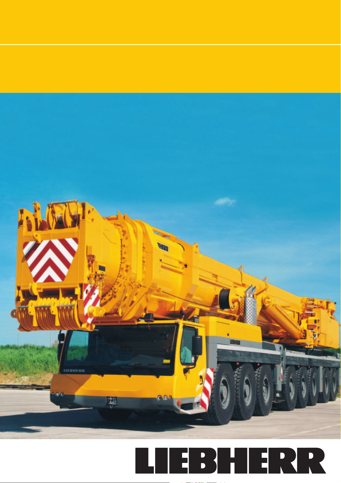
LTM 1500-8.1
mobile crane
Max. lifting capacity: 500 t at 3 m radius
Max. height under hook: 145 m with lattice luffing jib
Max. radius: 108 m with lattice luffing jib
Page 2
16.6
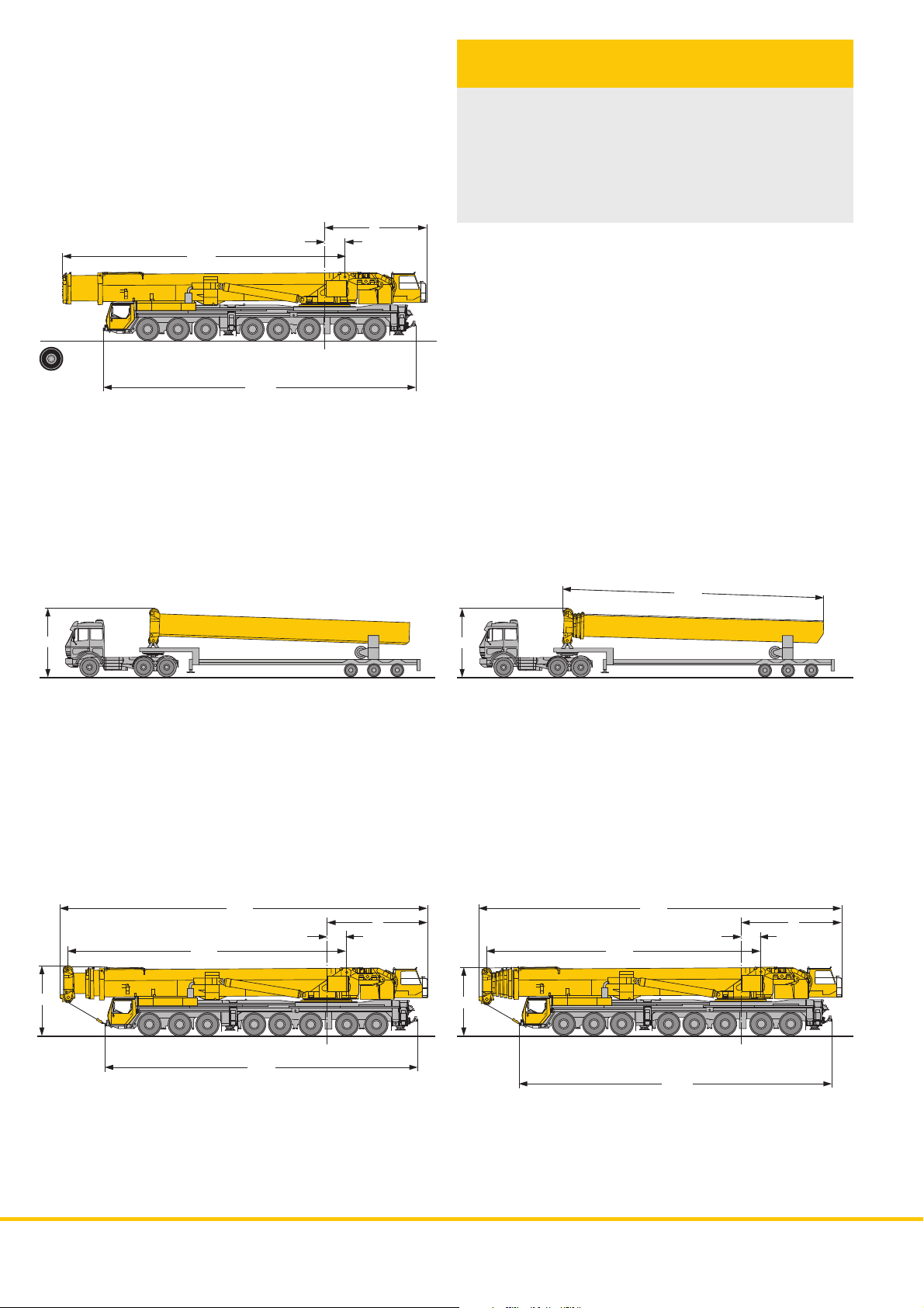
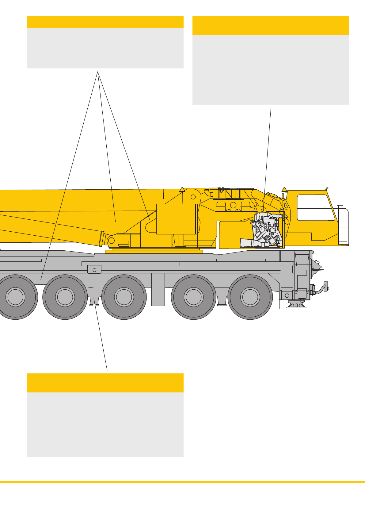
The variable telescoping
boom system
• 96 t total weight incl. 50 m telescopic boom and permanent
outrigger system
• Boom change device with hoisting and displacement
mechanism on low loader
• Quick Connection for the dismantling of the telescopic boom
(10 t axle load)
• Quick Connection for the dismantling of the superstructure
(6 t axle load)
6
1.2
14.00 R25
4
10.6 t
10.6 t 10.6 t
10.6 t
+
18.4
Tele 3
11.8 t
11.8 t
11.8 t
11.8 t
or
+
15.3
Tele 3 + 4 + 5 + 6
4
=
21.6
16.4
6
1.2
50 m
4
12 t12 t12 t12 t
18.4
12 t
12 t12 t12 t
=
21.3
16.1
6
1.2
84 m
4
14.7 t
14.7 t
14.7 t14.7 t
12.5 t
12.5 t
18.4
12.5 t
12.5 t
2
LTM 1500-8.1
Page 3
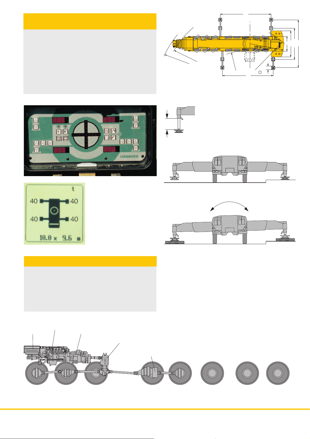
Setting on outriggers – quick,
convenient and safe
• Permanent supporting pads
• Supporting rams with 500 mm travel
• Automatic levelling of the crane during the supporting
procedure
• 2 x 9° lateral inclination, even with locked suspension
• Inclinometer (electronic display of inclination) with two
indicators on the carrier and one display on the LICCON
monitor
• Indicators of supporting forces on the carrier and on the
LICCON monitor
• Control of sliding outriggers with display of the state of
extension on the LICCON monitor (optional)
500500
R = 16.25
R = 15
10
R = 7.15
10
10
R = 6.6
R = 12.2
R = 12,2
0,7
0.7
3
3
5.2
9.6
6.25
Robust drive concept
• 4 axles permanently driven (1st, 2nd, 4th and 5th axle)
• 6 axles are steered;
independent steering of axles 7 and 8
• Automated gear system ZF-TC-TRONIC with converter
and retarder, 12 forward and 2 reversed speeds, automated
control
• Transfer case
• Driving axles with longitudinal differential locks
radiator
1st axle
driven
steered
Diesel engine
D9508 A7
2nd axle
driven
steered
Transmission
ZF-TC-TRONIC
transfer case
3rd axle
non driven
steered
eddy-current
brake
4th axle
driven
steered
5th axle
driven
non steered
6th axle
non driven
non steered
7th axle
non driven
steered
8th axle
non driven
steered
LTM 1500-8.1
3
Page 4
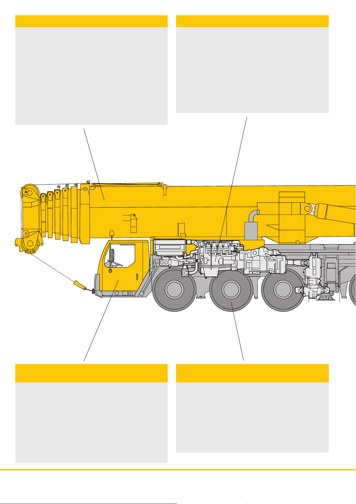
Outstanding boom technology
Powerful carrier drive
• Focal points of the new boom technology:
- oviform boom profile
- patented internal interlocking system of
the telescopes
- automatic telescoping system
• Telescopic boom with electronically controlled telescoping
system
• Boom bearings of low maintenance polyamide
slide blocks
• Outstanding lifting capacities, e.g.
161 t at 10 m radius
77 t at 20 m radius
37.4 t at 40 m radius
21.4 t at 60 m radius
13 t at 80 m radius
3.6 t at 108 m radius
• 8-cylinder Liebherr turbo-charged Diesel engine D9508 A7
of 500 kW/680 hp, exhaust emissions acc. to 97/68/EG stage
3 and EPA/CARB Tier 3, energy-saving, emission-optimized,
robust and reliable, electronic engine management
• Automated gear system ZF-TC-TRONIC with converter
and retarder, 12 forward and 2 reversed speeds, automated
control
• Transfer case
• Robust crane axles, welded design
• Max. driving speed 80 km/h
• In addition to the service and parking brakes, the following
sustained-action brakes: Exhaust brake with Liebherr auxiliary
brake system by valve control, intarder filled to transmission,
Telma-type eddy current brake on 4th axle
Data bus technique revolutionizes
crane electric system
• The data transmission to the individual functional blocks is
realized digitally by just a few data cables instead of the
traditional electrical wiring. Thus, increased functional reliability
and essentially less contacts
• Self-manufactured bus systems, especially adapted to the
requirements of a mobile crane
• The vehicle and crane electrics with all cockpit functions, the
outrigger system and the boom sensor system are
interconnected by 6 Liebherr system busses
• Comprehensive diagnostic facilities, quick
localization of errors
• The new data bus technique provides a distinctive increase
in functionality and efficiency
4
4
Outstanding carrier technology for
road and off-road application
• Weight optimized and low maintenance axles of high-tensile
steel; perfect track keeping and lateral stability due to special
control linkage arrangement
• Steering knuckles mounted on steel bearings, thus bearing
failures are practically ruled out
• The perfected and robust axles are manufactured in large
series and are part of the trouble-free components of a mobile
crane
• The cardan shafts in the axles are maintenance-free and are
safely located within the axle body. 70° diagonal toothing
enables easy and fast fitting by just a few screws.
LTM 1500-8.1
LTM 1500-8.1
Page 5
Weight-optimized steel structure
• Carrier, superstructure and telescopic boom in light-gauge
design, calculated by the F.E.M. method, weight-optimized
and of particular torsional rigidity
• Tensile property of material with high safety factors through
the application of STE 960 (960 N/mm2) for all supporting
members
Crane drive with proved
components
• 6-cylinder Liebherr turbo-charged Diesel engine type D936L
A6 of 240 kW/326 h.p, exhaust gas emissions in accordance
with the directives 97/68/EG stage 3 and EPA/CARB Tier 3,
electronically controlled engine speed, engine located laterally
to the rear of the superstructure
• Pump distribution gear with 4 servo-controlled axial piston
variable displacement pumps operating in a closed oil circuit
for winches 1, 2, 3 and slewing gear; 2 servo-controlled
double axial piston variable displacement pumps in an open
oil circuit for luffing/telescoping; oil cooler within the hydraulic
oil circuit
Crane and road-preserving
Niveaumatik suspension
• Maintenance-free suspension rams, free of lateral forces and
protected by synthetic tubes
• Level adjustment (suspension set to ”travel mode”) can be
performed automatically by push-button control from any
position
• Stable cornering ability due to cross mounting of the hydraulic
suspension
• Axle locking system (locking of the suspension for travelling
with equipment) integrated into the suspension ram and
controllable from the driver’s cabin
LTM 1500-8.1
5
Page 6
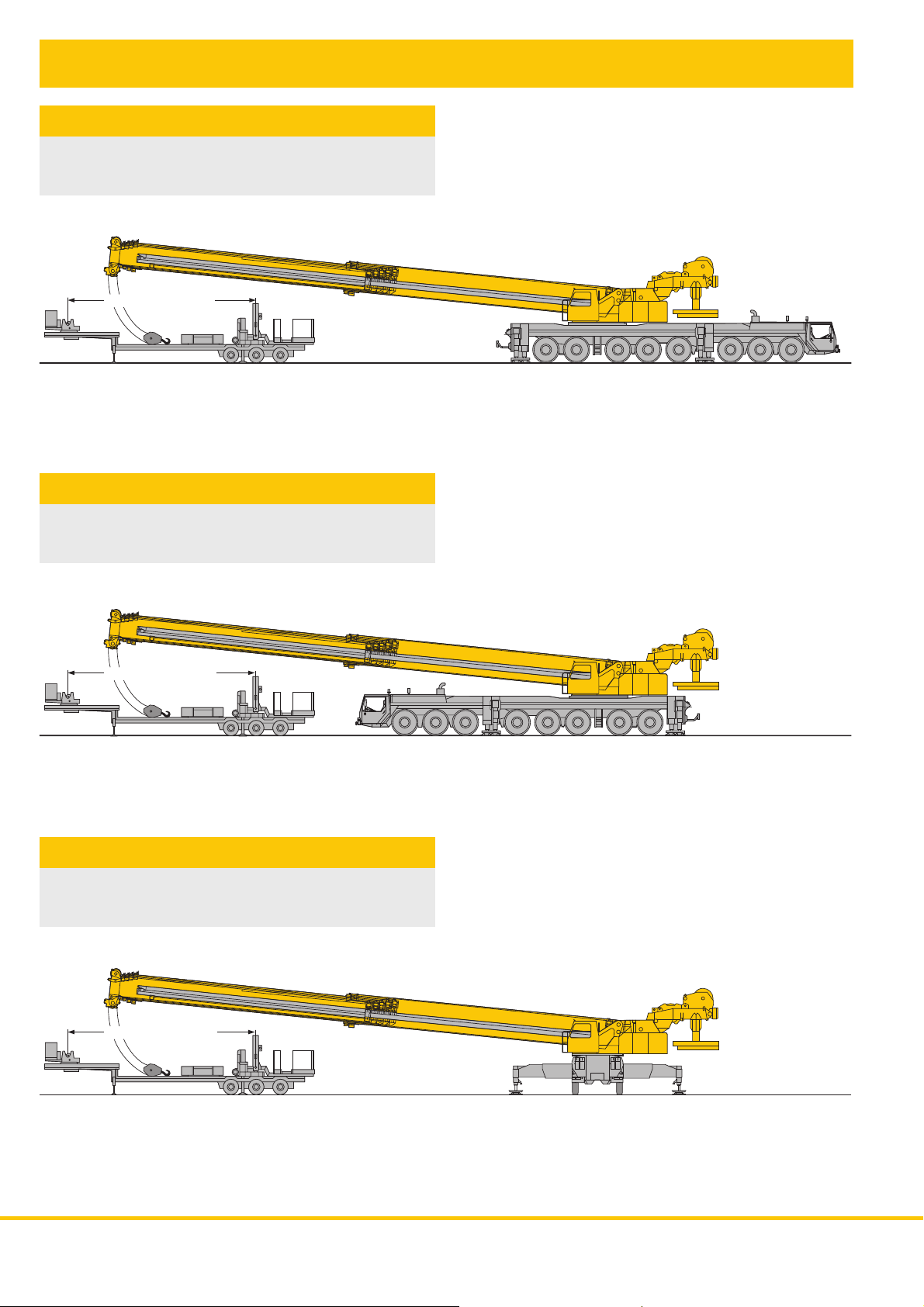
Dismantling of telescopes 2 - 6 or 3 - 6 respectively over the vehicle’s rear,
front or side
Variant 1
Crane on outriggers, dismantling over the vehicle’s rear
Minimum counterweight with 2 – 6 telescopes 30 t
min. 9 – max. 11 m
3 – 6 telescopes 15 t
Variant 2
Crane on outriggers, dismantling over the vehicle’s front
Minimum counterweight with 2 – 6 telescopes 30 t
min. 9 – max. 11 m
3 – 6 telescopes 30 t
Variant 3
Crane on outriggers, dismantling over the side
Minimum counterweight with 2 – 6 telescopes 30 t
3 – 6 telescopes 15 t
min. 9 – max. 11 m
6
LTM 1500-8.1
Page 7

Sequence
Extend telescopes 2 or 3 to 100 %.
Retract telescoping ram and interlock it with
telescopes 1 or 2.
Extend telescopes 1 or 2 until the interlocking pin is accessible.
Put the boom head slightly on the low loader and dismantle
the upper slide blocks of telescope 1 or 2. Lower the telescopic
boom slightly in order to dismantle the lower slide pads. Remove
the slide pads from telescope 1 or 2. Release the interlock
between telescope 1 and 2 or 2 and 3 respectively by means
of the emergency release screw. Extend the supporting frame
of the low loader and raise telescopic sections 2 – 6 or 3 – 6
respectively.
LTM 1500-8.1
Retract telescope 1 or 2 and lower the boom on to the low
loader.
Lock the boom to the supporting frame by the lateral pressure
plates. Lock the boom head in the supporting device by the
ratchet.
16 m
min 9 – max 11 m
7
Page 8

Load handling – precise and safe
• 7-section, 84 m long telescopic boom for 84 m height under
hook and 74 m radius
• Considerable gain in lifting height and reach due to the
exceptionally long boom
• 4-section, 50 m long telescopic boom for 50 m height under
hook and 48 m radius
• Oviform boom profile of particular torsional rigidity and for
the highest capacities
• Patented internal interlocking system of the telescopes - of
functional reliability and maintenance-free
• High functionality of the boom system due to the automatic
telescopic system ”Telematik”
• Optimal utilization of the telescopic boom through numerous
telescoping variants
78.6 m
73.4 m
68.1 m
84 m
36.9 m
31.7 m
26,5 m
21,3 m
16,1 m
47.3 m
42.1 m
62.9 m
57.7 m
52.5 m
50 m
47.3 m
42.1 m
36.9 m
31.7 m
26,5 m
21,3 m
16,1 m
8
LTM 1500-8.1
Page 9

Multi-variable boom configuration
system
• Telescopic boom T, 16.1 m - 84 m, also with additional guying
system TY and with boom extension TV
• Fixed lattice jib TF, 14 m - 63 m, mountable at 0° or 20°, also
with additional guying system TYF
• Luffing lattice jib TN, 21 m - 91 m, mountable to the 16.1 m
- 78.8 m long telescopic boom at an inclination of 83°, 75°
and 67°, also with additional guying system TYN
• Intermediate sections of the TF and TN configuration are
identical and can be slid into one another for transportation
• Jib A-frames with T-adapter and N-base section form a
complete mounting/transport unit and can be mounted with
4 pins only
• Easy-to-rig stay rods which remain on the intermediate
sections during transportation
• Standard auxiliary winch for easy reeving of the hoist and
luffing ropes
• Rigging of the jib is practicable in suspended condition on
restricted sites
• Winch 2 for 2-hook operation or for operation with mast nose
• Winch 3 for luffing of the jib
150 m
140 m
130 m
120 m
110 m
100 m
90 m
80 m
70 m
60 m
50 m
T/TY TF/TYF/TVYF T/TYTN/TYN/TVYN TF/TYF TN/TYN
LTM 1500-8.1
40 m
30 m
20 m
10 m
9
Page 10

• The electrical and electronical components are interconnected
by the most modern data bus transmission technique
• Self-manufactured bus systems, especially adapted to the
requirements of a mobile crane
• Diesel engine and automatic transmission are controlled by
a CAN data bus system. The fully electronic drive management
reduces fuel consumption and improves the emission of
exhaust gases
• The electric systems of the vehicle and crane as well as all
cockpit functions, the systems of the outriggers and sensors
of the boom are interconnected by 6 Liebherr system busses
• Digital data transmission to the individual functional blocks
by only a few data cables instead of the traditional electrical
wiring; thus increased functional reliability and essentially
less contacts
• The control of the functional blocks is realized by I/O modules,
the programming of which is performed by means of the
Liebherr system busses. The control intelligence is integrated
into the LICCON central units
• Comprehensive diagnostic facilities, quick error localization
• The new data bus technique distinctively increases functionality
and efficiency
17
18
10
6
7
5 1
1a
CAN-Bus
2a
LSB 2
2
LTM 1500-8.1
Page 11

LSB 5
19
LSB 1
15
LSB 4
16
3a
14
12
LSB 6
13
3
8
LTM 1500-8.1
11
Page 12

Legend
LSB Liebherr system bus 1
LSB Liebherr system bus 2
LSB Liebherr system bus 3
LSB Liebherr system bus 4
LSB Liebherr system bus 5 (also for TN mode)
LSB Liebherr system bus 6 (also for TA mode)
CAN busse
SCI serielle communication interface
1 Input/output modules for electronic control of suspension,
Liebherr Diesel engine, automatic transmission, operating
functions, compressed air control for brake function
1a Instruments-key board unit in driver’s cabin
2 Input/output module for differential locks, display functions
3 Input/output module for outriggers - right
3a Control unit for outriggers - right
4 Input/output module for outriggers - left
4a Control unit for outriggers - left
5 Input/output module for engine brake, tempostat, temposet,
electronic control of Diesel engine (steering column switch,
right) and automatic transmission
6 Control of Allison automatic transmission
7 Control of injection pump Liebherr Diesel engine/carrier
8 Slewing sensor slipring unit
9 Connection Liebherr system bus (LSB 1, 2, 3, 4, 5, 6)
10 LICCON central unit
11 LICCON monitors in the crane cabin
12 Length sensor
13 Cable drum/energy cable for interlocking gripper/telescopic
boom
14 Inductive sensors (12 x)
15 Angle sensor on the base section
16 Cable drum for items 17, 18, 19 and jib
17 Wind sensor
18 Hoist limit switch
19 Angle sensor
20 Input/output module for electronic control of Diesel
engine/superstructure, air flap, ventilator clutch,
exhaust flap
21 Control of injection pump Liebherr Diesel
engine/superstructure
11
CAN-Bus
2021
10
11
LSB 3
9
LTM 1500-8.1
4a4
12
Page 13

Comfortable driver’s cabin of
outstanding functionality
• Modern and comfortable driver’s cab of high functionality
and convincing design
• Heat and sound absorbing internal panelling
• Ergonomically arranged operating and display elements for
safe and convenient handling at permanent operation
• Digital display and keyboard units interconnected with the
functional blocks by data bus technique
• Air-cushioned driver’s and co-driver’s seats, headrests, driver’s
seat with pneumatic lumber support
• Height and inclination adjustable steering wheel
• Heated and electrically adjustable rear mirrors
• Side panes with electrical lifters
• Engine independent auxiliary warm water heater
• Safety belts for driver and co-driver
• Green-tinted windows for heat absorption
• Automatic windscreen washers/wipers with
intermittent control
• Delayed disconnection of interior lighting
• Various racks and boxes for crane documentation, etc.
• Optional equipment
Air conditioning, seat heating, 3rd seat with headrest, sleeper
berth, cassette radio
13
LTM 1500-8.1
Page 14

Comfortable and spacious
crane cabin
• Galvanized crane cab with tinted panes all-round, front
knockout window with large parallel windscreen wiper, large
skylight of bullet-proof glass with large parallel windscreen
wiper, roller blind on skylight, space-saving sliding door, cabin
inclinable backwards
• Green tinted front and side panes for heat absorption
• Wash/windscreen wiper for front window and skylight
• 2 working projectors, 70 watt each, at the front and rear of
the cabin
• Engine independent additional warm water heater
• Optional equipment
Air conditioning, seat heating, roller blind on rear pane,
cassette radio
• Spring-mounted and hydraulically cushioned crane operator’s
seat with pneumatic lumber support and headrest
• Convenient armrest-integrated controls, vertically and
horizontally adjustable master switch consoles and armrests,
ergonomically inclined operating consoles
• Heat and sound absorbing internal panelling
• Display of all essential operating functions on the LICCON
monitor
14
LTM 1500-8.1
Page 15

LICCON computer system
with practical application programs
• Serial application programs: Safe load indicator, configuration
program with configuration image, operating program with
operating image, telescoping program with telescoping image,
supporting pressure indication, control parameter program,
test system; optional extra: work area limitation and LICCON
work planner
LTM 1500-8.1
15
Page 16

LICCON-assisted telescoping system
• Telescoping by single-stage hydraulic ram with hydraulic
driving tenons
• Telescoping procedure controllable on the LICCON monitor,
convenient and simple guide mode on the monitor, precise
approach of the interlocking positions
• Telescopable loads are displayed on the LICCON operating
image
• ”Automatic operation”, fully automatic telescoping to the
desired boom length, rapid-cycle system with high working
speeds
• Extremely light telescoping system, thus increases in lifting
capacity with long booms and at large radii
• Automatic cushioning of telescopes in end positions during
telescoping and retracting for preserving the structural
members
The LICCON work area
limitation system
• It relieves the crane operator, especially in situations where
the handling of loads requires his full attention, by controlling
the work area limits. Work areas can be restricted by buildings,
bridges, roofs, high-tension lines, pipe lines or adjacent
cranes. The automatic work area limitation system can easily
be programmed and is clearly understandable. Four different
limitation functions are practicable:
• Height limitation of the pulley head
• Radius limitation
• Slewing angle limitation
• Limitation of edges
LTM 1500-8.1
16
Page 17

The LICCON test system
• The test system assists the servicing personnel in quickly
localizing errors of the sensor system without needing any
further measuring instruments
• Convenient interactive functions permit the observation of
all in- and outputs of the general system by different displays
on the monitor even during crane operation. It equally visualizes
the allocation of the individual sensors to the system as well
as their function and the terminals concerned in the control
cabinet
• The table of contents enables the display of the contents
and state of development of the program modules as well
as the load charts on the monitor
• The service starts on the monitor, error detection becomes
a matter of seconds
The service and diagnostic
system LISSy
• This service and diagnostic system LISSy enables the data
base-protected control of the programmed errors including
error text, description of the cause of error as well as the
measures to be taken for the elimination of those errors
• The system provides a quick diagnostic analysis due to the
rapid online access to the service documentation such as
electric circuit diagrams and workshop manual
• The possibility to memorize the experiences of the crane
users in respect to the administrated errors contributes to a
progressive growth of the service and diagnostic system
LISSy to a data base of experience and knowledge
The LICCON work planner
• The LICCON work planner consists of a software program
for planning, simulation and documentation of crane
applications on the monitor
• The 2-D planner allows to draw buildings, to write texts and
to represent a crane model true to scale including its entire
motions within a fictional construction site
• The work planner enables the preparation of more transparent
offers, it facilitates the briefing of the crane operators and it
can be run on a laptop at the construction site
17
LTM 1500-8.1
Page 18

15 t
15 t
15 t
15 t
15 t
15 t
15 t
15 t
15 t
105 t
165 t
135 t
Multivariable counterweight system
• Ballast variants of 165 t, 135 t, 105 t, 90 t, 75 t, 45 t, 30 t and
15 t, thus a considerable application spectrum
• Counterweight slabs of ideal transport dimensions
• The counterweight base slab (15 t) and 6 counterweight slabs
(15 t each) as well as the winch frame with winch 2 and 3
can be mounted as a complete unit
Counterweight erection:
• Pile up the counterweight slabs on the carrier frame, the base
slab with the ballasting rams forms the carrying plate
• Pick up the winch frame including winch 2, and winch 3 if
required, lower it into the fixing devices of the ballasting rams
and bolt it
• Pile up the lateral counterweight slabs, depending on the
requirement (a total of 4 slabs, 15 t each)
• Connect the hydraulic devices and the remote control panel.
• Extend the ballasting rams and push the winch frame including
winches 2 and 3 upwards
• Swing superstructure into the longitudinal axis of the winch
frame
15 t
15 t
15 t
15 t
15 t
15 t
15 t
15 t
15 t
15 t
15 t
15 t
15 t
15 t
15 t
15 t
105 t
165 t
135 t
105 t
• Lower the winch frame by retracting the ballasting rams and
enter the centering pins into the location holes of the
superstructure. Continue to retract the ballasting rams and
raise the counterweight slabs until they sit close to the winch
frame
• Disconnect the hydraulic and electric connections
18
LTM 1500-8.1
Page 19

Counterweight frame – compact
and quickly mountable
• Modular set-up of the counterweight frame, consisting of
base frame and two winch packages, compact transport unit
• Winch 2 and winch 3 with luffing block are pinned and thus
quickly interchangeable if required, e.g. for the application
of a second LTM 1500-8.1
• The winches are connected to the hydraulic system of the
crane by rapid action couplings
• Auxiliary winch with control panel for reeving of the hoist
rope and luffing rope
LTM 1500-8.1
2480
R = 6600
5200
19
Page 20

Electric/electronic crane control with integrated safe load indicator
• Control of the winches, slewing gear as well as of the luffing
and telescoping motions by the LICCON system (SPS control)
• Four working motions can be performed independent of one
another
• Hoisting/lowering, slewing and luffing speeds are preselectable
by 5 steps
• Luffing speed controlled automatically dependent on the
boom length
• Very short response rate when initiating the crane motions
LICCON
monitor
LICCON
monitor
telescoping
control
levers
engine
control
2 Liebherr double
variable displacement
pumps
• Hoist gear and slewing gear are operating within a ”closed
oil circuit”. This enables a particularly precise hoisting, lowering
or slewing of the load. More-over, the potential energy
generated during the lowering of a load is not converted into
heat but can be re-employed for a 2nd motion. This offers
the particular advantage in saving fuel and in a reduced
thermal exposure of the oil than in an open circuit.
No overheating of the oil.
single-stage
telescoping
ram with
hydraulic
interlocking
device
luffing
ram
luffing winch (jib)
control block
hoist winch I
transmitters,
sensors
LICCON
control
slewing gear
4 variable
displacement
pumps
hoist winch II
Liebherr Diesel engine D936L A6
Subject to modifications
Liebherr-Werk Ehingen GmbH
Postfach 1361, 89582 Ehingen, Germany
콯 +49 7391 5 02- 0, Fax +49 73 91 5 02-33 99
www.liebherr.com, E-Mail: info.lwe@liebherr.com
PN 231.01.E12.2009
 Loading...