

Page 1
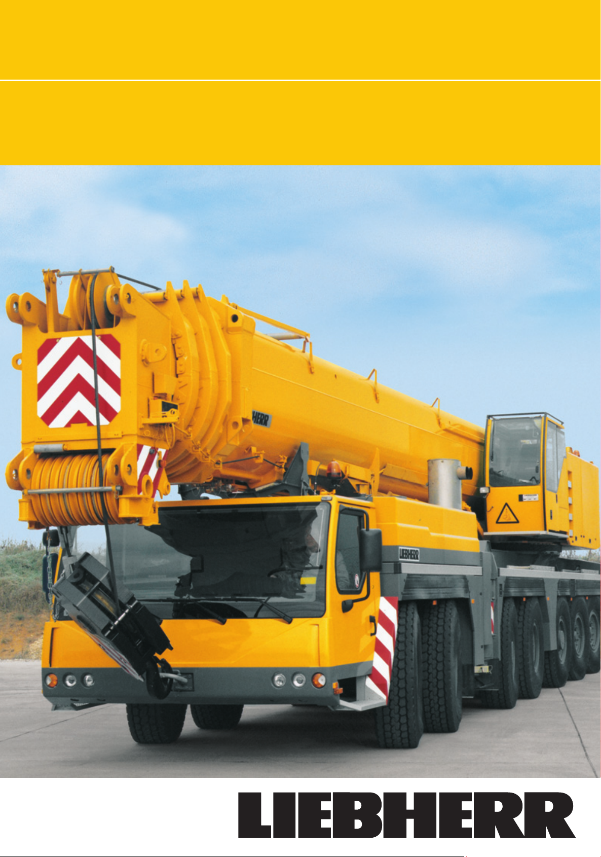
Product advantages
mobile crane
Max. load capacity: 400 t
Max. height under hook: 130 m
Max. radius: 100 m
LTM 1400-7.1
Page 2
4
11° 19°
14.00 R 25
1.9
R=13.1
R=14.05
12 t 12 t 12 t 12 t 12 t 12 t 12 t
R=11.4
16.56
18.45
R = 6.8
10
0,7
R = 5.6
R = 6.6
Compact, maneuverable and safe
• Overall length 18.45 m, carrier 16.56 m long
• Overhang angles, front up to 11°, rear up to 19°
• Smallest turning radius by active rear-axle steering, 13.6 m
over carrier
• Drive 14 x 6, axles 1, 3 and 5 are driven
Drive 14 x 8, axles 1, 3, 5 and 6 are driven; 6th axle activatable
for off-road displacement
• Driving axles with differential locks for lateral blocking to
increase the off-road quality
• Total weight 84 t, uniform axle load distribution (12 t) due to
3
6.8
6.23
hydropneumatic suspension "Niveaumatik"
9.5
• Telescopic boom guying system can technically carried along
by the crane
• For safe displacement, in addition to the service and parking
brakes, retarder in the TC-TRONIC gear and exhaust retarder
with Liebherr-additional braking system by valve control (ZBS)
as standard features; TELMA eddy-current brake on the 4th
axle (optional)
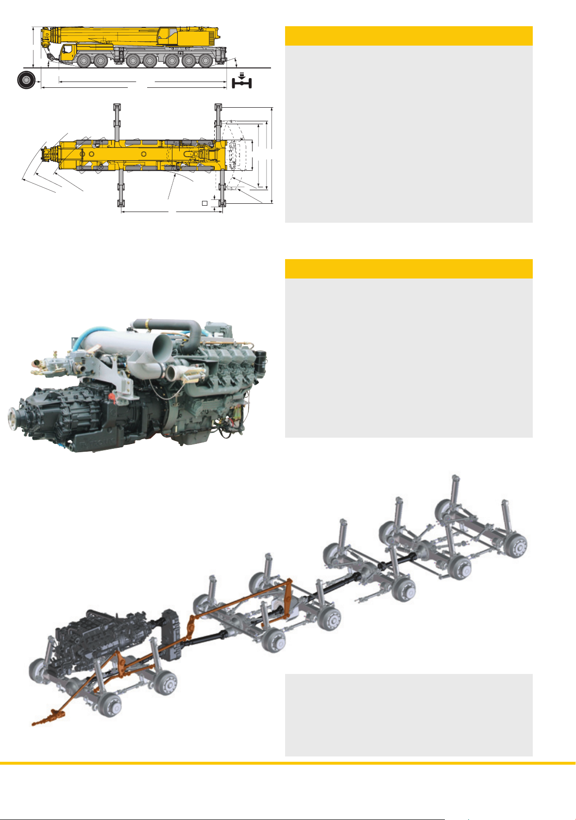
Modern drive concept
• Powerful, 8-cylinder Liebherr turbo-charged Diesel engine
D9508 A7 of 450 kW/612 hp, exhaust emissions acc. to
97/68/EG stage 3 and EPA/CARB Tier 3, robust and reliable,
modern electronic controlled engine management
• Automated gear system ZF-TC-TRONIC with converter and
retarder; 12 forward and 2 reversed speeds, automated
control
• Reduced fuel consumption due to a great number of speeds,
sensitive maneuvering due to converter
• 1-step, robust transfer case with transfer differential
• Weight-optimized, robust axles of minor maintenance, good
track keeping due to special drag-links and precise lateral
guidance; maintenance-free steering nuckles mounted on
steel-armoured rubber
• Maintenance-free cardan shaft; simple and quick fitting due
to 70° diagonal toothing
• Lateral force and maintenance free suspension rams, rams
protected against damage by plastic pipes
• Level regulation (suspension on "displacement mode") can
be performed automatically by pushbutton control from any
position
• Stable cornering ability of the crane due to cross-linkage of
the hydropneumatic suspension
• Max. displacement speed 80 km/h, max. gradability 39 %
LTM 1400-7.1 LTM 1400-7.1LTM 1400-7.1
Page 3
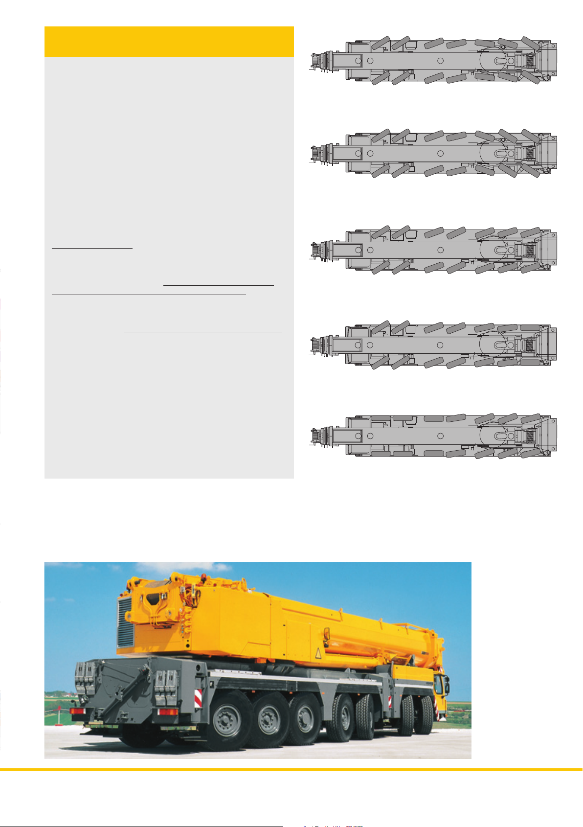
Variable steering concept with "active
rear-axle steering"
Axles 4 – 7 provided for "active rear-axle steering”, 5 steering
methods are preselectable by fixed programs (P)
P1 Road displacement steering
Axles 1 – 3 are steered mechanically by means of the steering
wheel with hydraulic assistance. Axles 4 and 5 are steered
“actively”, speed-dependent up to 30 km/h in relation to the
degree of lock of the front axle, and set and blocked to straight
displacement at over 30 km/h. Axles 6 and 7 are steered
“actively”, speed-dependent up to 60 km/h, in relation to the
degree of lock of the front axles, and set electrohydraulically
to straight displacement up to 60 km/h. The modification of
the steering angle in dependance of the speed guarantees a
precise and stable displacement quality and reduces the
abrasion of the pneumatics.
P1
P2
P2 All-wheel steering
Axles 4 – 7 are locked in conformance with the steering angle
of the 1st axle by means of the steering wheel to realize the
smallest turning radii.
P3 Crab steering
Axles 4 – 7 are locked in the identical sense of axles 1 – 3 by
means of the steering wheel.
necessary for crab steering as all axles are steered.
P4 Steering without swerving out
Axles 4 – 7 are locked in relation to the steering angle of the
1st axle to prevent
P5 Manual crab steering
Axles 1 – 3 are steered by means of the steering wheel, axles
4 – 7 are steered independently from the steering lock of axles
1 – 3 by pushbuttons.
• In case of a failure of the active rear-axle steering, it is rendered
ineffective and the rear axles are set to straight travel by the
centering rams
• Two independent hydraulic circuits with wheel and engine
driven hydraulic pump, thus maximum safety standard
• Two independent steering processors
(by existing E/A modules) and divergent sensory system
• The entire know-how for the "active rear-axle steering"
by Liebherr
any swerving out of the rear of the carrier.
The raising of the axles is not
P3
P4
P5
LTM 1400-7.1LTM 1400-7.1
310
Page 4
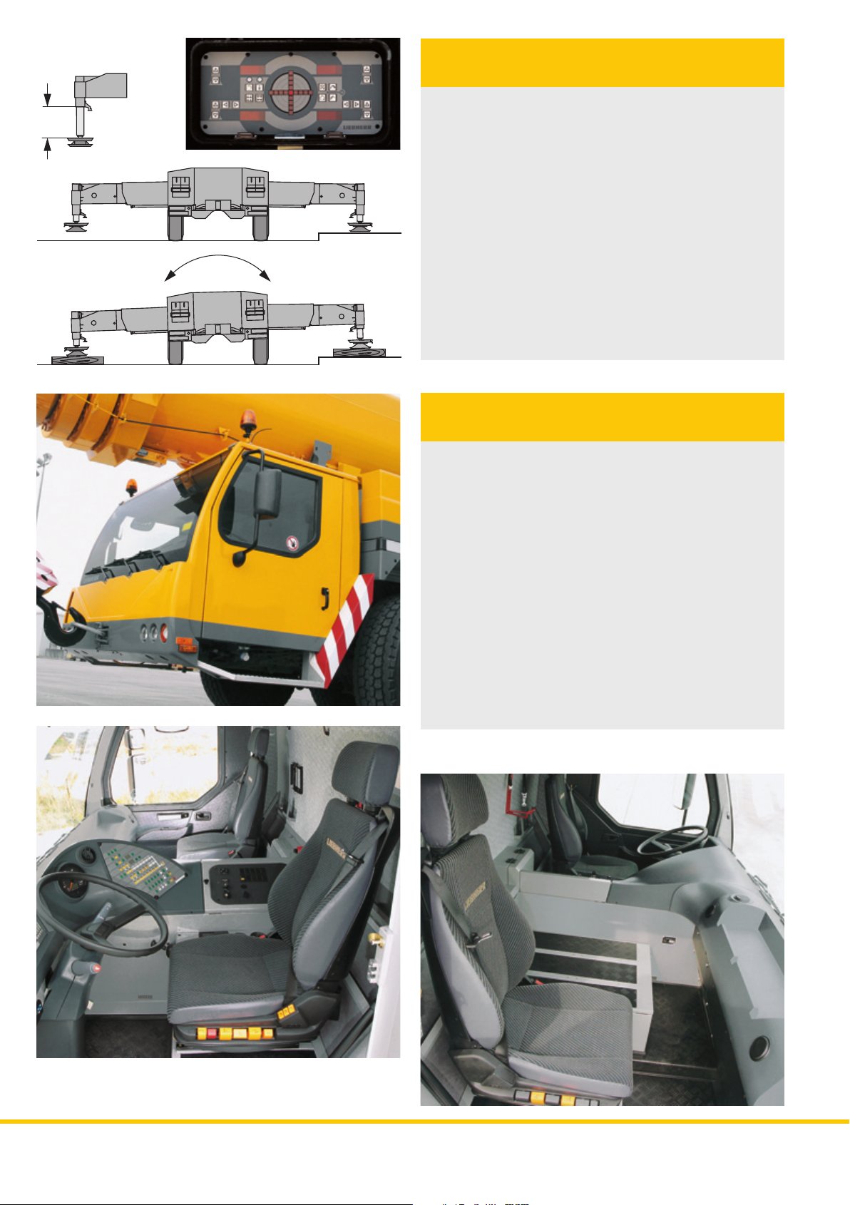
600
Setting crane on outriggers –
quick, convenient and safe
• Supporting basis: 10 m x 9.5 m or 10 m x 6.23 m
• Fixed suporting pads with lateral compensation
• Supporting rams with 600 mm travel
• Level control of the outriggers, all-automatic levelling of the
crane during the supporting procedure by "push-button
control"
• 2 x 9° lateral inclination of the carrier, thus simple underlay
of the supporting pads
• Inclinometer (electronic inclination indication), two displays
on the carrier and a display on the LICCON monitor in the
crane cab
• 2 supporting force indicators on the control panels on the
carrier and on the LICCON display screen to indicate the
supporting force on the supporting rams
• 4 projectors for the illumination of the supporting zone
• Axle locking (blocking of the suspension for the displacement
with equipment) controllable from the driver’s cab
• Operation of the outrigger system in accordance with the
rules for the prevention of accidents
Comfortable driver’s cab of
outstanding functionality
• Modern driver’s cab of outstanding functionality and
convincing design. Corrosion resistant sheet steel version,
cataphoretic dip-primed, front section mounted on shock
absorbers, rear damped hydraulically, internal sound and
heat absorbing panelling
• Safety glas all-round, greenish tinted front and side windows
for heat insulation, electric window lifters
• 3 automatic windscreen washers/wipers with intermittent
control
• Heated and electrically adjustable outer rear mirrors
• Air-cushioned driver’s and co-driver’s seat with headrests,
driver’s seat with pneumatic lumber support
• Safety belts for driver’s and co-driver’s seat
• Height and inclination adjustable steering wheel
• Standardized, digital operating and control instruments
arranged ergonomically for safe and convenient handling,
arranged operator-friendly in a half-round shape
• Digital display and keyboard units interconnected with the
functional blocks by data bus technology
• Additional heater with engine preheating
4 9
LTM 1400-7.1 LTM 1400-7.1
Page 5

Comfortable crane cab of outstanding
functionality
• Crane cab in corrosion-resistant, galvanized sheet steel
version, pouder-coated, with sound and heat insulating
internal paneling, interior of modern design, tinted window
panes all-round, front knockout window with large windscreen
wiper and wish/wash device, skylight of bullet-proof glas
with large parallel windscreen wiper and wish/wash device,
roller blinds on front window and skylight, space-saving
sliding door
• Greenish tinted front and side windows for heat absorbtion
• Pneumatic operated lateral foot board for safe access to and
from the carrier
• Crane cab tiltable to the rear by 20° to improve the sight
• 1 working projector 70 Watt, at the cabin front
• Spring-mounted and hydraulically cushioned crane operator’s
seat with pneumatic lumber support and headrest
• Operator-friendly armrest-integrated controls, vertically and
horizontally adjustable master switch consoles and armrests,
ergonomical adjustable operating consoles
• Ergonomical control levers with integrated winch and slewing
indicators
• Modern instrument support with integrated LICCON monitor,
display of all essential operating data on the LICCON display
screen
• Additional heater with engine preheating
LTM 1400-7.1LTM 1400-7.1
5
Page 6

Crane drive with field-proven
components
• Crane engine: 6-cylinder Liebherr turbo-charged Diesel engine
type D936L A6 of 240 kW/326 h.p, exhaust gas emissions
in accordance with the directives 97/68/EG stage 3 and
EPA/CARB Tier 3, robust and reliable, electronic engine
management, optimated fuel consumption, exhaust gas
system of special steel
• Hydraulic system with 5 variable axial piston pumps with
servo-control and capacity regulation, auxiliary pumps for
central feeding and ventilator drive, electric driven oil cooler
• Standard high-efficiency noise absorption of the dieselhydraulic crane drive
Winch technology by Liebherr
• Self-manufactured Liebherr winches (1, 2 and 3) with special
grooving, with incorporated planetary gears and springmounted multi-disk brakes as static brakes
Winch 1
main hoist gear
Winch 1 Winch 2Auxiliary
Winch 3
winch
Winch 2
auxiliary hoist gear, required for 2-hook operation with luffing
lattice jib
Winch 3
for variation of the luffing lattice jib
Auxiliary winch
for reeving of the hook block and for the erection of the lattice
luffing jib
• Drive of the hoist gear within a "closed oil circuit", i.e. during
lowering of the load, the oil motor is propping itself up on
the variable displacement pump due to the closed oil circuit
(hydraulic shaft). The potential energy is not converted into
heat, but can be re-employed for an additional movement.
Besides a saving in fuel, the hydraulic oil is less thermically
exposed than in an "open oil circuit"
• Axial-piston variable displacement motor of own manufacture,
specially laid out for crane operation, exposed to tough
fatigue test and field-proven
• Display of the rotary motion of the winch on the LICCON
display screen
• Non-rotating hoist rope, standard rotation absorber
• Video control of the winches (standard in conjunction with
the jib variation winch)
Page 7

Counterweight assembly – just a
matter of minutes
• 140 t total counterweight, 100 t basic counterweight,
40 t additional counterweight
• Hydraulic ballasting device on the counterweight frame
• "60-t-package" of just 3 m transport width, mountable by
one lift
• Hoist gear 2 fitted to the counterweight frame
• Jib variation winch (winch 3) to be pinned on the counterweight
frame
• The counterweight radius can be reduced from 6.6 m
to 5.6 m by the displacement of the entire counterweight
• Reeving winch (auxiliary winch) on the counterweight frame
as standard equipment
Partial counterweight, radius 5.6 m 140 t total counterweight, radius 6.6 m
60 t-package with winch 3 Luffing jib mode, counterweight radius 5.6 m
or 6.6 m
LTM 1400-7.1LTM 1400-7.1
76
Page 8

Outstanding boom technology
• 5-section, 60 m long telescopic boom in light-gauge design,
weight-optimized by FEM processing
• Material stability with high safety factors by the application
of ultra-high grain refined steels, boom bottom shell of
S 1100 QL (1100 N/mm
• Optimated, oviform boom profile with continuous curvature
in the bottom shell and upper offset joint, high stability against
deflection for maximum load capacities
• Outstanding functionality of the boom system due to the
automated, electronically controlled telescoping system
"Telematik"
• Patented internal locking system of the telescopes – reliable
and maintenance-free
• Optimal utilization of the telescopic boom due to a multitude
of telescoping variants
• All telescopes are also telescopable under partial load
• Y-guying system for the telescopic boom for a distinctive
increase of the load capacity
• The telescopic boom is always kept straight in its geometry,
ineffected by lateral sun radiation or side wind. For that
purpose, the stay ropes of the Y-guing system are wound
onto two accumulator blocks on the Y-frames by two rope
winches. Grips, pressed onto the stay ropes, define the rope
lengths in relation to the telescopic boom lengths; limit
switches control the positioning of the pressed-on grips; the
stay ropes are locked to the pressed-on grips by means of
tensioning rams in the Y-frames.
• Self-assembly of the Y-frames; carrier width/height with fitted
and laterally hinged Y-guying system: 3.03 m/4.07 m
2
)
8
Page 9

Multi variable boom configuration
system
• Telescopic boom T, 15.4 m – 60 m
• Telescopic boom guying system TY, 5.25 m wide "spacer"
for TYSF and TYSN mode
• Fixed lattice jib TF (TYSF), 7 m - 56 m, mountable at 0°, 20°
or 40° on the 15.4 m – 60 m long telescopic boom
• Lattice luffing jib TN (TYSN), 14 m – 84 m, mountable on the
15.4 m – 56.4 m long telescopic boom
• Continuous load capacity interpolation during luffing of the
boom configuration TN (TYSN) between 82° and 68° telescopic
boom inclination
• Intermediate sections TF and TN equipment are identical,
intermediate sections can be slid into one another for
transportation
• Jib A-frames with T-adapter and N-base section form a
complete mounting/transport unit and can be fitted with just
4 pins
• Easy-to-rig stay rods which remain on the intermediate
sections during transportation
• Auxiliary winch on the counterweight frame for easy reeving
of the hoist and luffing ropes
• Rigging of the jib can be performed in suspended condition
on restricted sites
• Winch 2 for 2-hook operation on the lattice jib
• Winch 3 for jib variation. The variation winch forms one unit
with the variation block. The variation rope remains reeved
during transportation.
12.6
6.46.2
38°
38°
R = 10
R = 9.8
56.5 m
51.4 m
46.3 m
41.1 m
36 m
30.8 m
60 m
R = 6.6
R = 5.6
T 60 m
F 56,6 m
F 28 m
F 21 m
F 14 m
F 7 m
T 56.6 m
F 56 m
F 49 m
F 42 m
F 35 m
56.6 m
51.4 m
46.3 m
20°
F 49 m
40°
F 49 m
46.3 m
82°
N 56 m
N 49 m
N 42 m
N 35 m
N 28 m
N 21 m
oviform boom profile
N 70 m
N 63 m
68°
N 77 m
N 84 m
130 m
120 m
110 m
100 m
90 m
80 m
70 m
60 m
50 m
40 m
T/TY
TF / TYF
15.4 m
30 m
20 m
10 m
0 m
TN / TYN
Page 10

Data bus technology for more
functionality and efficiency
• The electric and electronic components are interconnected
by the most modern data bus transmission technology
• Digital data transmission to the individual functional blocks
by just a few data cables instead of the conventional electric
wiring; thus increased functional reliability due to essentially
less contacts
• Self-manufactured Liebherr bus systems (LSB), specially
matched for the requirements of a mobile crane
• Diesel engine and automatic transmission are controlled by
means of a CAN data bus. The all-electronic drive
management reduces fuel consumption and improves the
exhaust gas emission
• The electric systems of the carrier and the crane as well as
all cockpit functions, the outrigger system and the boom
sensory system are interconnected by 4 Liebherr-system
busses
• The control of the functional blocks is realized by E/A modules,
the programming of which is performed by means of the
Liebherr system busses. The control intelligence is integrated
into the LICCON central unit
• Comprehensive diagnostic facilities, quick error localization,
operating error indication
• Test programs for functional test of the keyboard and display
unit as well as for the test of the control units of engine and
transmission management, Liebherr additional brake system,
hydraulic ventilator, hydraulic suspension and outrigger control
units
• The new data bus technology distinctively increases the
fuinctionality and efficiency of the mobile crane
16
17
LSB 1
LSB 5
LSB 3
LSB 4
18
Legende
LSB Liebherr system bus 1
LSB Liebherr system bus 2
LSB Liebherr system bus 3
LSB Liebherr system bus 4
LSB Liebherr system bus 5
LSB Liebherr system bus 6
CAN busse
SCI serielle communication interface
1 Input/output module for electronic control of the suspension,
Liebherr Diesel engine, automatic transmission, control
functions, pneumatic control for brake function
1a Instruments-keyboard unit in driver’s cab
2 Input/output module for differential locks, display functions
2a Instruments-display unit in driver’s cab
3 Input/output module for outriggers - right
3a Control unit for outriggers - right
4 Input/output module for outriggers - left
4a Control unit for outriggers - left
5 Input/output module for engine brake, tempomat, temposet,
electronic control Diesel engine (steering column switch right)
and automatic transmission
6 Control ZF-TC-TRONIC automatic transmission
7 Control injection pump Liebherr Diesel engine/carrier
8 Slewing sensor in slipring unit
9 Connection Liebherr system bus (LSB 1, 2, 3, 4, 5,6)
10 LICCON central unit
11 LICCON monitor in crane cab
12 Length sensor and cable drum/energy cable for interlocking
gripper//telescopic boom
13 Inductive sensor
14 Angle sensor on base section
15 Cable drum for items 16, 17, 18 and lattice luffing jib
16 Wind sensor
17 Hoist limit switch
18 Angle sensor
19 Input/output module for electronic control of the Diesel
engine/superstructure, ventilator clutch, exhaust flap
20 Control injection pump Liebherr Diesel engine/superstructure
21 Joystick selector
22 Pressure sensor for output management and LMB (safe load
indictor) and supporting pressures
23 Angle sensor active rear-axle steering
24 Steering block active rear-axle steering
25 Pedal telescoping
26 Winch rotation sensor
27 Inductive sensor Y-guying system
1a
14
15
6
5
1
7
CAN-Bus
3a
23
LSB 1
22
3
8
CAN-Bus
13
27
12
CAN-Bus
LSB 6
20
19
11
9
10
26
21
21
2a
LSB 2
25
2
LTM 1400-7.1LTM 1400-7.1
24
23
4 4a
1110
Page 11

LICCON configuration and
operating program
• Serial application programs: Safe load indicator (LMB) ,
configuration program with configuration picture, operating
program with operating picture, telescoping program with
telescoping picture, supporting pressure indication, control
parameter program, test system; optional extras: Work area
limitation and the LICCON work planner
• Setting of the configuration by convenient interactive functions
• Safe and conscious acknowlegement of the adjusted
configuration
• Representation of all essential data by graphic symbols on
the operating picture
• With integrated wind speed measuring system
• Reliable cut-off device when exceeding the admissible load
moments
• Load capacity values for any boom intermediate length
• Winch display for precise lifting/lowering of the load
LICCON-assisted telescoping system
• Telescoping by single-stage hydraulic ram with hydraulic
driving tenons (patented internal locking system)
• Telescoping procedure controllable by covenient operator
guide on the monitor, the interlocking positions are precisely
approached
• Telescopable loads are displayed on the LICCON operating
picture
• Rapid-cycle telescoping system with "automatic mode", i.e.
all-automatic telescoping to the desired boom length
• Very compact and light-weight telescoping system, thus load
capacity increases especially with long booms and at large
radii
• Automatic cushioning of the telescopes in end positions
during telescoping and retracting to preserve the structural
members
12112
Page 12

The LICCON test system
• The test system assists the servicing personnel in quickly
localizing errors of the crane‘s sensory system without the
need of measuring instruments
• The service starts at the display screen, trouble shooting
becomes a matter of seconds
• Occurring errrors are indicated by error codes and error
descriptions on the display screen
• Convenient interactive functions permit the observation of
all in and outputs of the general system by different
representations on the monitor, even during crane operation.
It also visualizes the allocation of the individual sensors and
actuators to the system as well as their function on the display
screen
The LICCON work area limitation
• It relieves the crane operator, especially in situations where
the handling of loads requires his full attention, by controlling
the work area limits. Work areas can be restricted by buildings,
bridges, roofs, high-tension power lines, pipe lines or adjacent
cranes. The automatic work area limitation (optional) can
easily be programmed. Four different limitation functions are
practicable:
• Height limitation of the pulley head
• Radius limitation
• Slewing angle limitation
• Limitation of edges
The LICCON work planner
• The LICCON work planner consists of a software program
on CD for planning, simulation and documentation of crane
applications on the display screen (optional)
• The 2-D planner program permits the drawing of buildings,
to write texts and to represent a crane model true to scale
including its entire working motions within a fictional
construction site
• The work planner enables the preparation of more transparent
offers, it facilitates the briefing of the crane operators and
can be run on a laptop at the construction site
LTM 1400-7.1
13
Page 13

Electric/electronic crane control with integrated safe load indicator
• Control of the winches, the slewing gear as well as the luffing
and telescoping motions by the LICCON system (PLC control)
• Four working motions can be performed independent from
one another
• Hoisting/lowering and luffing speeds are preselectable by
5 steps
• The luffing speed is controlled automatically in relation to the
the boom length
LICCON
monitor
Joystick
selectors
telescoping engine
control
• Very short response rates at the activation of crane motions
• Joystick selectors with vibrating motion detectors
• Slewing motion continuously controllable from
0 – 1,5 min-1, additionally 6 steps between 10 % and
100 % preselectable by the LICCON control
• Electrohydraulic interlocking system of the superstructure
over front and over rear
single-stage
telescoping
ram with
hydr.
interlocking
device
jib variation
winch
luffing rams
control block
hoist winch I
1 double variable
transmitters
sensors
slewing gear
LICCON control
displacement
displacement
pump
hoist winch II
Liebherr Diesel engine D936L A6
4 variable
pumps
Optional features contribute to an expansion of the application spectrum
and increase comfort and safety
On the carrier
• Eddy-current brake
• Outrigger control
• Rope box
• Air-conditioning system
• Radio preparation
• Seat heating for driver’s and co-drivers seat
• 3rd seat
• Maneuvering coupling
• Fog lamps
• CD radio set
On the crane superstructure
• Air-conditioning system
• Seat heating
• Video control of the winches
• Work area limitation program
• Working projector Xenon on the telescopic boom base section
• GSM module for tele diagnostic
• CD radio set
Further optional features by request
Subject to technical modifications.
Liebherr-Werk Ehingen GmbH
Postfach 1361, 89582 Ehingen, Germany
콯 +49 73 91 5 02-0, Fax +49 73 91 5 02-33 99
www.liebherr.com, E-Mail: info.lwe@liebherr.com
PN 146.02.E07.2007
 Loading...