

Page 1
LICCON2
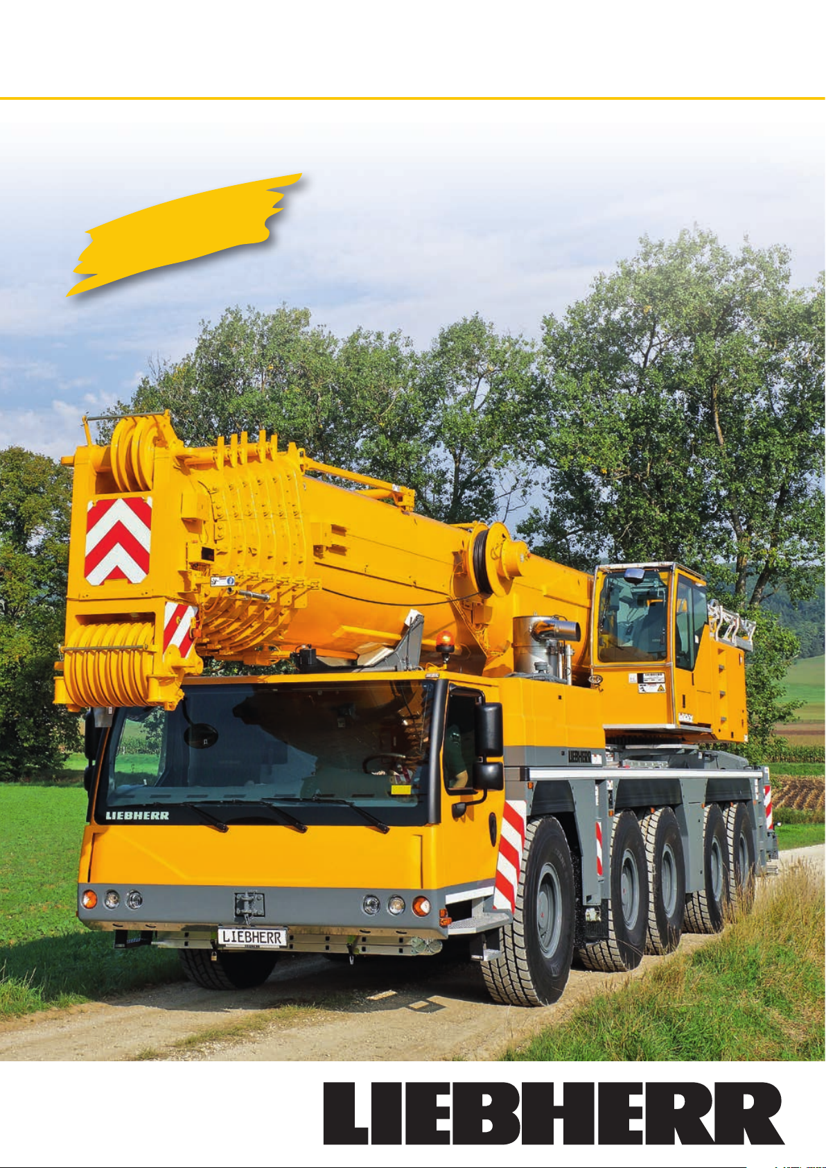
LTM 1200-5.1Mobile Crane
Max. lifting capacity: 200 t
Max. lifting height: 101 m
Max. working radius: 80 m
Page 2
Mobile Crane LTM 1200-5.1
Flexible and economical to operate
LTM 120 0-5 .1
2
Page 3
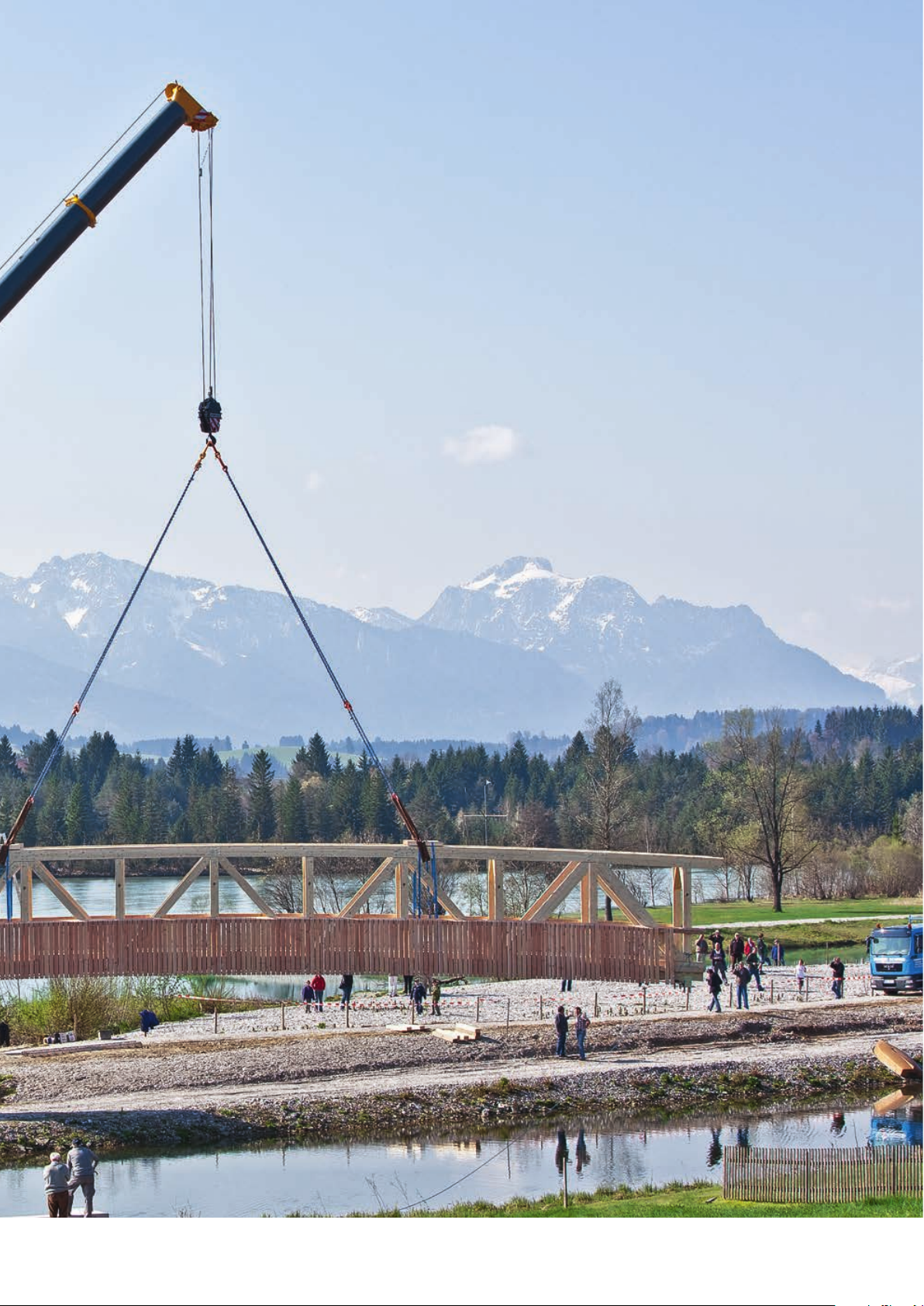
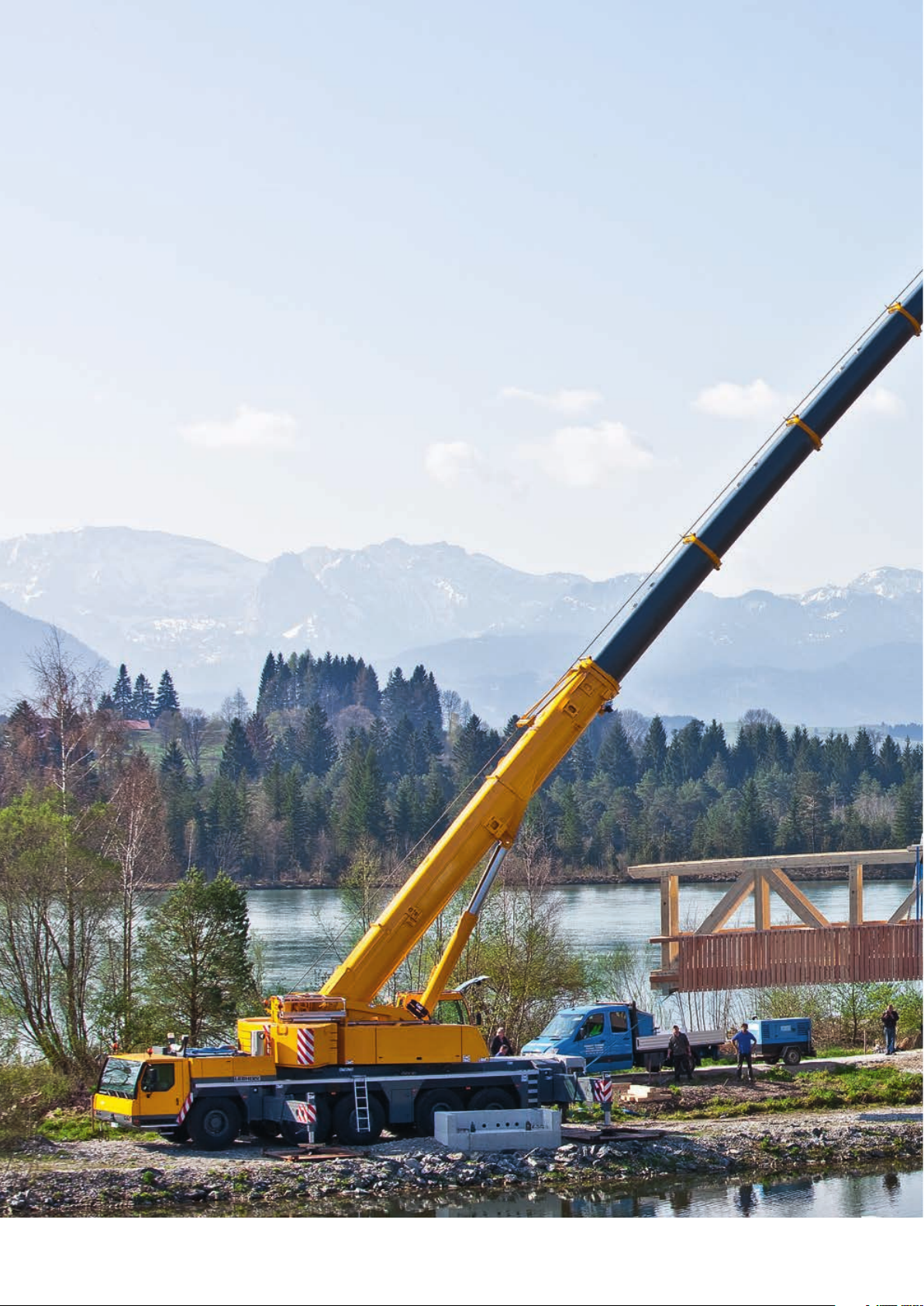
A long telescopic boom, high capacities, an extraordinary mobility as well as a comprehensive comfort and safety configuration distinguish the mobile crane LTM 1200-5.1
from Liebherr. The 200-tonne crane offers state of the art technology for more convenience in practical operation.
• 72 m long telescopic boom and 7 m telescopic boom extension
• 12.2 m – 36 m long folding fly jib, hydraulically adjustable (option)
• Capacity 10.6 t at the 72 m long telescopic boom
• Great flexibility of use due to optimum lifting capacities with full and partial
ballast
• Active, speed-depending rear-axle steering
• Pneumatic disc brakes
• LICCON2-control with mobile control and display unit BTT
LTM 120 0-5 .1
3
Page 4
LTM 120 0-5 .1
4
Drive train
• 6-cylinder Liebherr turbo-diesel
engine, 370 kW/503 HP, max. torque
2355 Nm
• Automated ZF-AS Tronic gearbox,
12 forward and 2 reverse speeds
• ZF intarder directly at the gearbox
• 2-stage transfer case, 0.5 km/h
crawling speed
• Axles 2, 4 and 5 driven, axle 1 as option
Page 5
15115
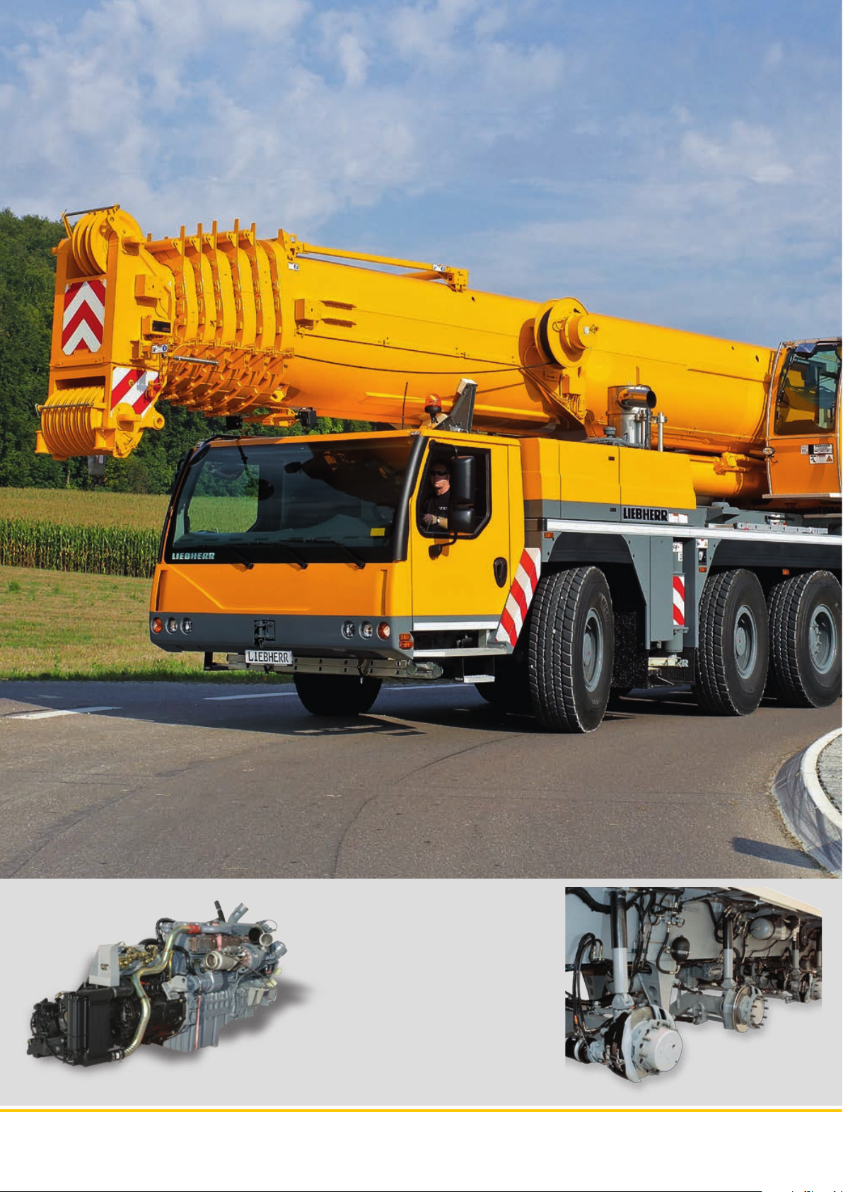
Most modern chassis and drive technology
High mobility and efficiency
A high performance 6-cylinder Liebherr turbo diesel engine with 370 kW/503 HP
provides for dynamic driving performance. The automatic 12-speed power shift
system ZF-AS Tronic with intarder provides a high level of cost effectiveness
and excellent comfort.
• Reduced fuel consumption due to the large number of gears and the high
efficiency of the dry clutch
• Excellent manoeuvrability and minimum crawling speed thanks to two-stage
transfer case
• Wear-free braking with ZF intarder
• Telma eddy current brake optional, wear free and comfortable
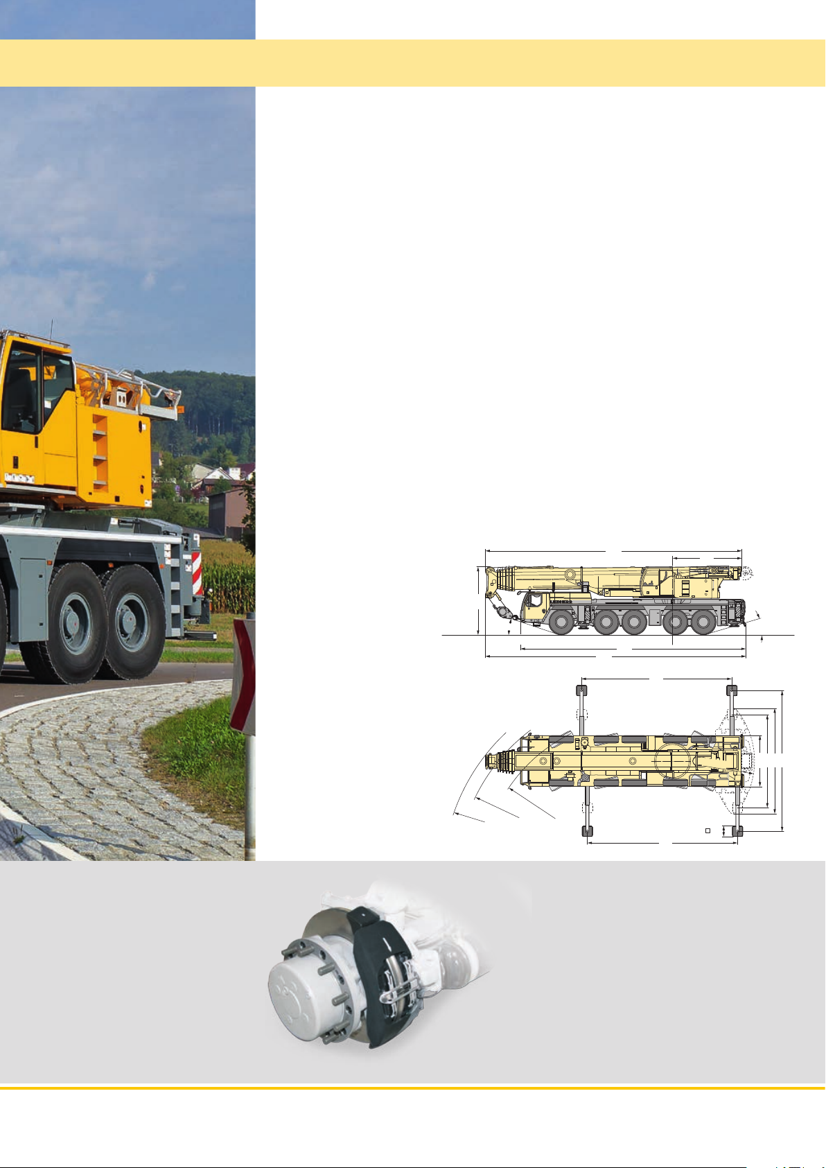
Compact, mobile and weight-optimised
Thanks to its compact design, the LTM 1200-5.1 can operate on the smallest of
construction sites.
• Chassis length 13.38 m
• Smallest turning radius 11.0 m
• Vehicle width 3.0 m, with tyres 445/95 R 25 (16.00 R 25)
• Ballast radius 4.85 m
4066
Hydro-pneumatic suspension
“Niveaumatik”
• Maintenance-free suspension cylinders
• Large dimensions to cope with high
axle loads
• Spring travel +150/-150 mm
• High lateral stability when cornering
• Choice of driving states using fixed
programmes
4000
R = 11850
17°
445/95 R 25 (16.00 R 25)
R = 11000
R = 9580
15370
13382
8879
R = 4850
8899
Pneumatic disc brakes
• Higher braking power, better brake control
• Improved track stability
• No brake fading at higher operation temperatures
• Higher service life
• Shorter working times for changing of the
brake pads
• Brake pads with wear indication
16°
6230
3000
5500
8300
600
S2670
LTM 120 0-5 .1
5
Page 6
LTM 120 0-5 .1
6
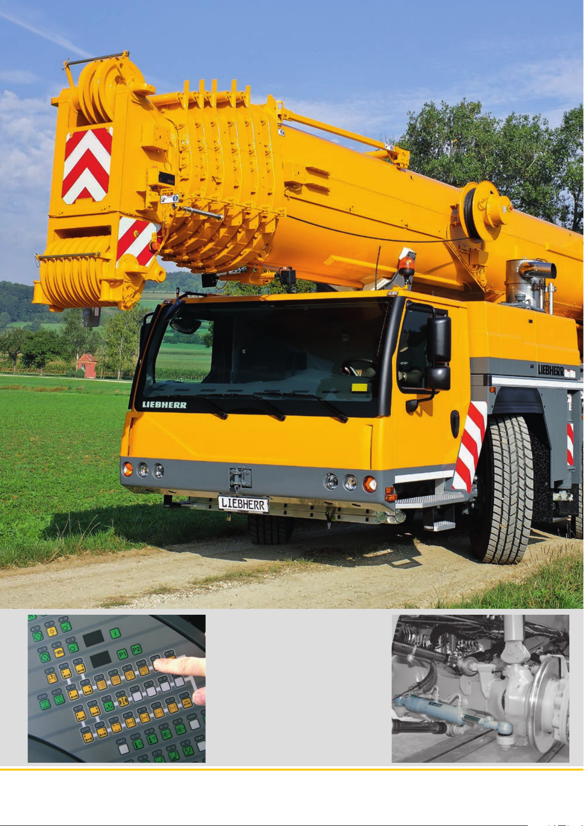
Five steering programmes
• Selection of programme by simple
push button
• Clear arrangement of control elements and displays
• Programmes can be switched while
driving
• Crab steering controlled in comfort
via the steering wheel
Page 7

Variable steering concept
Active rear-axle steering
The rear axles are electro-hydraulically actively steered depending on the speed
and the steering angle of the front axles. Five different steering programmes (P)
can be selected by push button.
• Distinct reduction of the tyre wear
• Improvement of the manoeuvrability
• Stabile driving performance even at high speeds
• All 5 axles steerable
High safety standards – entire know-how from
Liebherr
• Centring cylinder for automatic straightening of rear axles in case of failure
• Two independent hydraulic circuits with wheel- and engine driven hydraulic
pump
• Two independent control computers
Centring cylinder to straighten
rear axles
• Automatic straightening of rear
axles in case of failure
P1 Road steering
Axles 1 and 2 are steered mechanically
using the steering wheel. Axles 3, 4 and 5
are actively steered, depending on speed
and the front axles lock angle. At speeds
of 30 km/h and over, axles 3 and 4 are set
to straight-ahead position and locked; at
60 km/h and over, axle 5 is locked in the
same forward position.
P2 All-wheel steering
The axles 3, 4 and 5 are turned depending
of the axle lock of the front axles by the
steering wheel so far that smallest turning
radii are achieved.
P3 Crab steering
Axles 3, 4 and 5 are turned in the same
direction as the wheel lock on axles 1 and
2 using the steering wheel.
P4 Reduced swing out
The axles 3, 4 and 5 are turned depending on the axle lock of the front axles, so
that the swing out of the chassis rear gets
minimized.
P5 Independent rear-axle steering
The axles 1 and 2 are turned by using the
steering wheel; the axles 3, 4 and 5 are
steered by push button independently
from the axle lock of the axles 1 and 2.
LTM 120 0-5 .1
7
Page 8

LTM 120 0-5 .1
8
The driver’s cab
• Corrosion resistant
• Safety glass on all sides
• Tinted glass
• Electric window lifters
• Heated and electronically adjustable
outside mirrors
• Air-sprung driver’s seat with lumbar
support
Page 9

700
Comfort and functionality
Modern driving cab and crane cab
The modern driving cab as well as the backwards tiltable crane cab offer a comfortable and functional working place. The control elements and displays are
arranged according to ergonometric factors. Thus a safe and wear free working
is assured.
Speedy and safe set-up
The supporting, ballast assembly and attachment of additional equipment have
all been designed with speed, safety and comfort in mind. Specific ascents,
handholds and rails are provided to ensure the safety of operating staff.
Supporting crane on outriggers –
quick, comfortable and safe
• BTT blue tooth terminal, mobile
control and display unit
• Electronic inclination display
• Fully automatic levelling by push
button
• Engine start/stop and speed control
• Support area lighting with four integrated lights
• Support cylinder stroke: front
650 mm, rear 700 mm
• Outrigger beams 2-stage,
fully hydraulic, low-maintenance extension system
The crane cab
• Large field of vision
• Safety glazing
• Tinted window panes
• Crane driver’s seat with lumbar support,
multiply adjustable
• Heat and noise insulated interior cladding
• Corrosion resistant
• Working floodlight
• Can be tilted 20° backwards
LTM 120 0-5 .1
9
Page 10

LTM 120 0-5 .1
10
The fully automatic telescoping system
„TELEMATIK“
• Greater lifting capacities with longer booms
and larger radii thanks to ‚light‘ telescoping
system
• One-stage hydraulic cylinder with hydraulically operated drive pin
• Maintenance-free telescoping system
• Fully automatic telescoping
• Easiest control and monitoring of telescoping action on LICCON screen
5.4 m long assembly jib
Page 11

High lifting capacities and flexible boom system
Powerful, long telescopic boom and functional
lattice extensions
The telescopic boom consists of the base section and 6 telescopic sections,
which can be comfortably and automatically extended and pinned to the requested length by the thousand fold proven single cylinder telescoping system
TELEMATIK.
• 72 m long telescopic boom
• 12.2 m – 36 m long double swing-away jib, attachable at 0°, 22.5° and 45°
• Hydraulic adjustment of the swing-away jib at full load from 0° to 45°
(optional), interpolation of capacities
• Hydraulic assistance for assembly of the swing-away jib with BTT
• Intermediate section 7 m for extension of the telescopic boom for operation
with swing-away jib
High lifting capacities both with full and partial
counterweight offer a wide operational range
• High lateral stability due to the oval boom profile
• Optimized capacities due to the numerous extension variations
• Capacity 10.6 t at 72 m long telescopic boom
High capacities at unpinned telescopic lengths
• High telescopable capacities due to interpolation
• Separate charts for holding of the load at unpinned telescopic lengths
• Display at LICCON monitor
Holding capacity
Unpinned telescopic length
Telescopable capacity
Rooster sheave, foldable sidewise
Hydraulic assistance for assembly
of the swing-away jib with BTT
LTM 120 0-5 .1
11
Page 12

0
Hydraulic folding jib
0°- 22,5°
0°- 45°
108 m
104
100
96
92
88
84
80
76
72
68
64
60
56
52
48
82°
Adjustable folding jib (0° to 45°) Hose reel for the hydraulic
cylinder
44
40
36
32
28
24
20
16
12
8
4
LTM 120 0-5 .1
12
Page 13

Variable counterweight
Counterweight assembly – a matter of minutes
• Multiple counterweight variations from 0 t to 72 t
• Rapid ballasting with keyhole technology from within the crane cab
• Compact counterweight dimensions, at 52 t ballast only 3.75 m ballast width
• Tail swing only 4.85 m
10 t
10 t
10 t
10 t
10 t
10 t
12 t
Total ballast 72.0 t
13
12 t 12 t 12 t 12 t 12 t
LTM 120 0-5 .1
Page 14

LTM 120 0-5 .1
14
The hoist gear
• Liebherr hoist winch with internal
planetary gear and spring loaded multi
disk brake
• Rope pull 105 kN at the outer layer
• Max. rope speed 140 m/min
• 2. hoist gear optional
Page 15

High-power crane drive
With tried-and-tested components
The drive components for crane operation are constructed for high performance
and ensure sensitive and precise load handling. They are specially designed to
suit the crane’s usage and have been subjected to hard endurance tests.
• Crane engine: 4-cylinder Liebherr turbo diesel engine, 145 kW/197 HP, max.
torque 926 Nm, optimized fuel consumption by electronic engine management
• Sensitive motions of the hoist gears in closed hydraulic circuits
• Electric/electronic SPS-crane control via the LICCON-computer system
• In-house fabricated Liebherr winches, 105 kN rope pull at the outer layer,
less reeving necessary due to high line pull
The slewing gear
• Liebherr planetary gearbox, spring
loaded multi disk brake
• Sensitive motions in closed hydraulic circuit
-1
• Slewing speed from 0 – 1.3 min
infinitively variable
Sensor
LICCON
monitor
Control block
Contro l
unit
Telescoping
cylinder
Luffing
cylinder
Slewing gear
Contro l lever wit h touch di splays
Contro l
unit
Hoist gear I
The central greasing
• Standard central greasing device
for slewing bearing, boom bearing,
luffing cylinder and winch bearing
• Even supply of grease
• Filling quantity visible at any time
in transparent reservoir
Contro l
unit
Engine control
Contro l
unit
Hoist gear II
Liebherr diesel engine
LTM 120 0-5 .1
15
Page 16

LTM 120 0-5 .1
16
The LICCON test system
• Rapid localisation of problems without
any other measuring instruments
• Error code and description displayed
• Convenient interactive functions for
monitoring all inputs and outputs
• Displays functions and allocation of
sensors and actuators
Page 17

Intelligent crane control
For functional and safe crane operation:
the LICCON computer system
The soft and hardware of the mobile crane control is developed by Liebherr inhouse. The centre is the LICCON computer system (Liebherr Computed Control).
• Integrated LML load moment limiter
• Key components are in-house manufactured by Liebherr
• Guaranteed spare parts availability
• Worldwide proven under the most different climate conditions
• Operator friendly
The second control generation LICCON2 is the result of a continuous development by the Liebherr specialists and enables the adaption to the constantly increasing demands of the markets due to its modern and future oriented control.
The data bus technology
Liebherr mobile cranes are completely interlaced by the data bus system. All
important electric and electronic components are equipped with own micro
processors and communicate with each other by only limited data cables. For
the special demands of the mobile crane Liebherr has developed own data bus
systems (LSB – Liebherr-System-Bus). The data bus technology improves the
reliability, the comfort and the safety for road driving and crane operation:
• Higher reliability due to remarkable lesser electric cables and contacts
• Continuous self testing of the “intelligent sensors“
• Comprehensive diagnosis possibilities, fast fault finding
The LICCON working range
limiting system
• Makes the crane operator’s job easier by
automatically monitoring workspace restrictions such as bridges, roofs, etc.
• Simple programming
• Four different limitation functions:
- Pulley-head height limitation
- Radius limitation
- Slewing angle limitation
- Edge limitation
The LICCON work planner
• Computer programme for planning, simulating and documenting crane operations on a PC
• Representation of all the crane’s load
charts
• Automatic search for suitable crane
based on load, radius and lifting height
parameters
• Simulation of crane operations with
outline functions and supporting force
display
LTM 120 0-5 .1
17
Page 18

LICCON2 – safe and comfortable
Attaching and detaching of the
hook block
The BTT Bluetooth Terminal offers the crane driver the
possibility to attach or detach the hook block at the front
of the vehicle within sight, as the hoist winch and the luffing cylinder of the telescopic boom are remote controlled.
Wireless remote control
(option)
All crane motions can be controlled
outside of the cab.
• Higher efficiency
• Free view and closeness to the load
• Prevention of communication errors
Wireless remote control
between the crane driver and the
job site personnel
Colour monitor
The readability of the data on
the monitor of the LICCON2
control system in the crane
cab is enhanced by the
colour display. Warnings and
crane utilization are considerably better recognized.
Supporting the crane
By use of the BTT the mobile crane will
be setup comfortably and safely. Engine start/stop and speed regulation,
electronic inclination display and automatic levelling are standard. Optionally
the BTT can also display the outrigger
forces.
Touch displays
Below the joy sticks integrated in the armrests the touch
displays are installed, with
which the various operational
functions can be selected.
These are beside others the
supporting of the crane, the
adjustment of the working
floodlights as well as heater
and air condition controls.
PN 210.00.E02.2014
Liebherr-Werk Ehingen GmbH
Postfach 1361, 89582 Ehingen, Germany
+49 7391 502-0, Fax +49 7391 502-3399
www.liebherr.com, E-Mail: info.lwe@liebherr.com
www.facebook.com / LiebherrConstruction
The pictures contain also accessories and special equipment not included in the standard scope of delivery. Subject to modification
 Loading...