

Page 1
Mobile crane
Product advantages
Max. load capacity: 160 t
Max. height under hook: 95 m
Max. radius: 70 m
LTM 1160-5.1
Page 2
4000
21°
16.00 R 25
2394
15020
12 t 12 t 12 t 12 t 12 t
12346
14740
31364823
26°
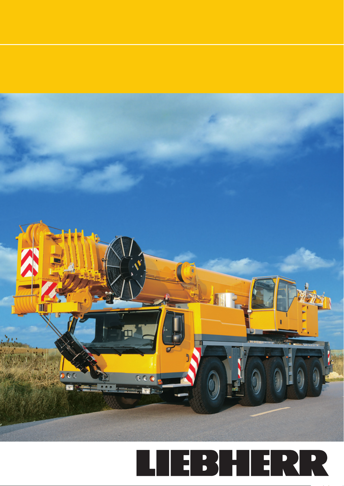
Compact, maneuverable
and weight-optimized
• Overall length 15.02 m, chassis length 12.35 m
• Large overhang angle of up to 26°
• Minimum turning-circle radius 10.6 m with all-wheel steering
• Rear ballast radius only 4.22 m
• 60 t gross weight, incl. 6.5 t ballast, 10 x 8 driveline,
16-inch tires, 26 t hook block (axle load 5 x 12 t)
• 3 optional tire sizes
14.00 R 25 (vehicle width 3 m)
16.00 R 25 (vehicle width 3 m)
20.5 R 25 (vehicle width 3.1 m)
R = 10600
R = 11800
R = 12300
R = 4220
R = 5100
7984
5310
7500
5000
3000
600
34964488
Modern drive concept
• Powerful, 6-cylinder Liebherr Type D846 A7 turbocharged
diesel engine, 370 kW/503 hp, exhaust emissions comply
with 97/68/EC Stage 3 and EPA/CARB Tier 3; robust and
reliable, with modern, electronic engine management
• ZF AS-TRONIC automated manual shift gearbox; ZF Intarder
fitted directly to gearbox; 12 forward and 2 reverse gears,
automated gear shift, high number of gear ratios helps to
reduce fuel consumption
• Robust 2-stage transfer box with lockable differential,
creep speed 0.78 km/h
• Drive 10 x 6: axles 2, 4 and 5 driven
• Drive 10 x 8 (optional): axles 2, 4 and 5 driven,
axle 1 can be engaged for off-road travel
• Robust, low-maintenance weight-optimized axles, special
arrangement of the maintenance-free suspension control
arms for excellent directional and lateral stability, steel and
rubber locating bushings
• Maintenance-free propeller shafts; easy and quick fitting
due to 70° degree cross-splines
• “Niveaumatik” hydropneumatic suspension, programcontrolled for raising crane onto outrigger supports, crane
travel with equipment and on-road crane travel; suspension
travel +150/-150 mm
• Maintenance-free suspension rams free from lateral forces,
piston rods protected against damage by plastic tubes
• Retarders:
Exhaust brake with additional Liebherr brake system (ZBS),
Intarder integrated in gearbox, Telma eddy current brake
(optional)
• Service brake:
All axles fitted with air-operated disc brakes, high braking
performance, extended maintenance intervals, rapid brake
pad renewal
LTM 1160-5.1 LTM 1160-5.1
Page 3
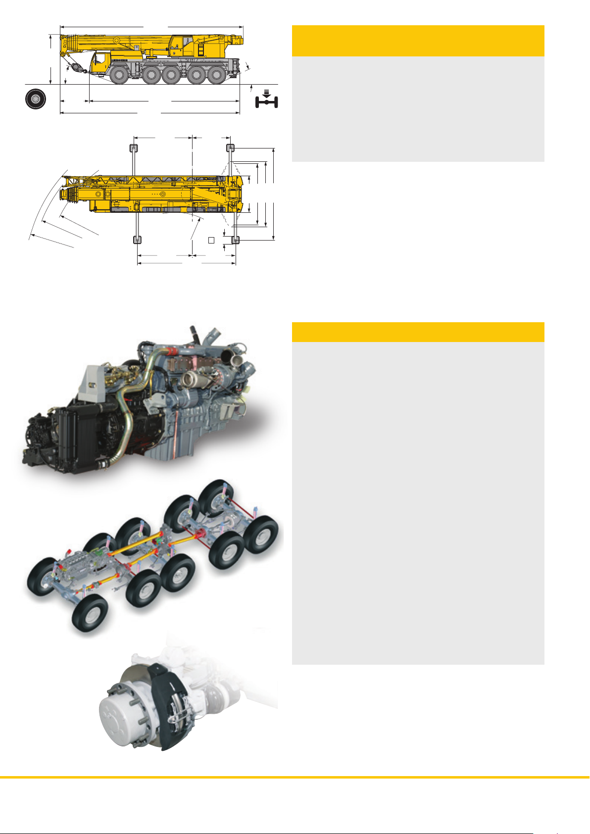
Variable steering concept
with „active rear-wheel
steering“
Axles 3, 4 and 5 incorporated into active rear-wheel steering
system; 5 steering methods can be preselected as fixed
programs (P):
P1: On-road steering
Axles 1 and 2 are steered mechanically from the steering
wheel, with hydraulic power assistance. Axles 3, 4 and 5 are
steered actively by a speed-dependent method according to
the front wheel lock angle. Above 30 km/h, axles 3 and 4 are
returned to the straight-ahead position and fixed. Above
60 km/h, axle 5 is also fixed in the straight-ahead position.
The change in steering lock angle according to road speed
results in precise, stable driving road behavior at higher speeds,
reduced tire abrasion and much-improved maneuverability
P2: All-wheel steering
Axles 3, 4 and 5, depending on the wheel lock angle of axle 1,
are turned by means of the steering wheel so that the smallest
turning-circle radius can be obtained
P3: Crabwise steering
Axles 3, 4 and 5 are turned into the same direction as axles 1
and 2 by means of the steering wheel
P4: Steering without superstructure
projection when turning
Axles 3, 4 and 5 are turned in accordance with the wheel lock
angle at axle 1, so that the rear of the vehicle does not project
when cornering
P5: Independent rear-axle steering
Axles 1 and 2 are turned by the steering wheel, axles 3, 4 and 5
are steered independent of the lock angle at 1 and 2 by
pushbuttons; at the same time the lock angle at axle 3 is
adapted to suit the actual situation
• A failure in the rear-axle steering shuts it down; the rear axles
are set to the straight-ahead position by centering rams
• Two independent hydraulic circuits with wheel-driven
and engine-driven hydraulic pumps for the maximum
level of safety
• Two independent control processors (by way of existing
input/output modules) and diversified sensor system
• The entire know-how for the active rear-wheel steering
comes from Liebherr
310
Page 4
700
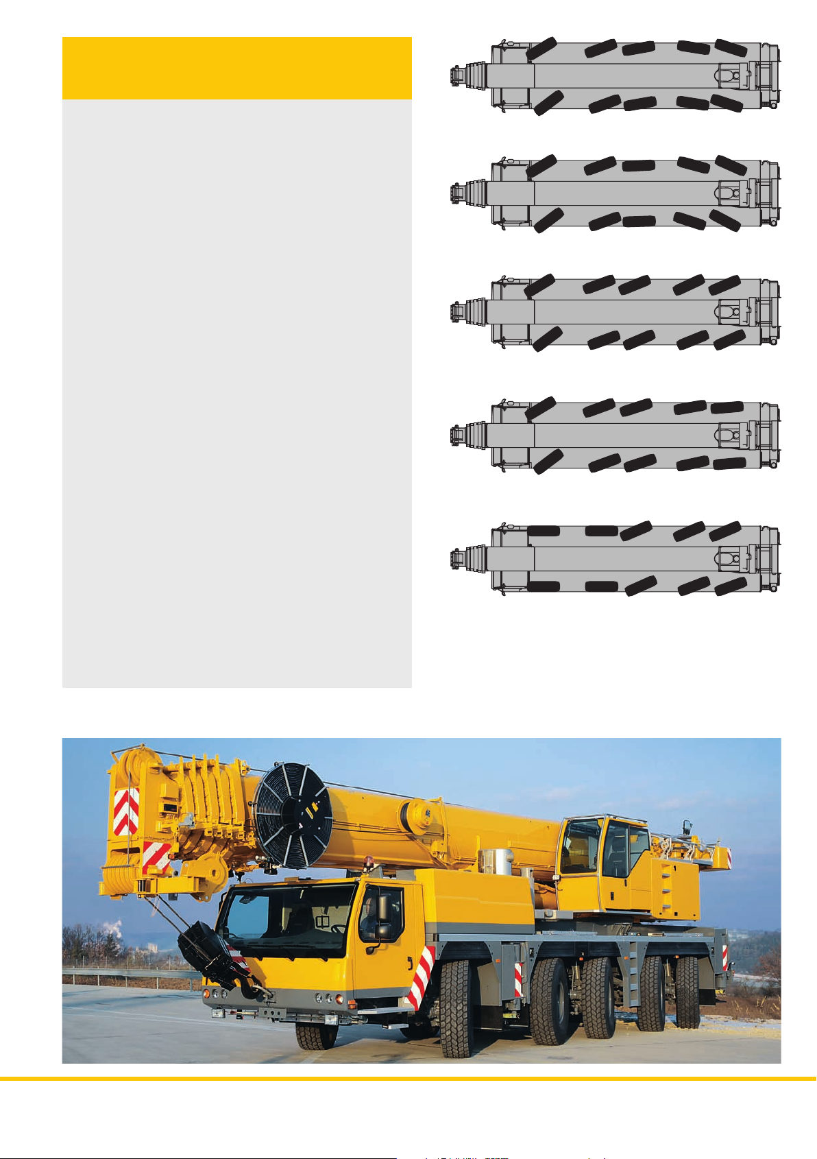
Supporting crane on outriggers –
quick, convenient and safe
• Variable support base width
Outriggers retracted
Support base area 5.0 m x 7.9 m
Support base area 7.5 m x 7.9 m
• Fixed support pads with splash guard
for protection against dirt
• Support jack extension range up to 700 mm
• Self-leveling of the outriggers, fully-automatic leveling of the
crane by pushbutton during the supporting procedure
•2 x 9° lateral inclination of crane chassis and superstructure
• Control panels at either side of the chassis with foil-covered
keyboard and electronic angle indicator, pushbuttons for
ENGINE/START/STOP and speed control are illuminated
and lockable
• Operation of the outrigger system in accordance with the
accident prevention regulations
• Illumination of the support area by 4 built-in lights
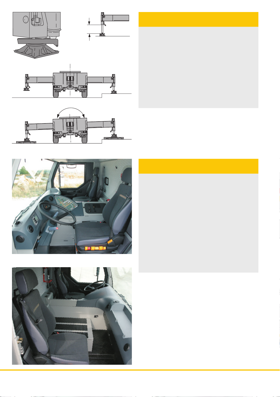
Comfortable, highly efficient
operator’s cab
• Modern, comfortable operator’s cab of highly efficient,
convincing design, corrosion-resistant sheet steel
construction, cataphoretic dip-primer coating, resilient rubber
front mountings, hydraulic damping at rear, sound and heat
absorbent interior paneling
• Safety glass all-round, sunproof green-tinted windshield and
side windows for heat absorption, electric window lifters
• Ergonomically correct arrangement of controls and displays
for safe and convenient handling for long periods
• Digital display and key-panel units interconnected with the
functional blocks by data bus technology
• Air-sprung driver’s seat with pneumatic lumbar
support and head restraint
• Steering wheel adjustable for height and angle
• Heated, electrically adjustable outside mirrors
• Seat belts for driver and co-driver
• 3 windshield wipers with automatic wipe/wash system and
intermittent-wipe setting
• Delayed switch-off of interior lighting
• Various storage shelves and compartments
• Preparation for radio
LTM 1160-5.1 LTM 1160-5.1
Page 5

Comfortable, highly efficient
crane cab
• Crane cab made from corrosion-resistant galvanized sheet
steel, powder-coated, with sound and heat absorbent internal
paneling, modern interior design, tinted windows all round,
opening windshield with large wiper and wipe/wash system,
armored-glass skylight with large parallel-action wiper and
wipe/wash system, roller sunblinds on windshield and
skylight, space-saving sliding door
• Green tinted windshield and side windows for heat absorption
• Pneumatically extending step for safe access to chassis
• Crane cab can be tilted to the rear by 20°
to improve view of work area
• 1 work-area light, 70 Watt, at front of the cab
• Sprung, hydraulically damped crane operator’s seat with
pneumatic lumbar support and head restraint
• Operator-friendly controls integrated into armrests, vertically
and horizontally adjustable joystick selector consoles and
armrests, ergonomically adjustable operating consoles
• Ergonomically designed control levers with integrated winch
rotation and slewing gear feedback device
• Modern instrument panel with integral LICCON monitor,
display of all relevant operating data on the LICCON screen
• Preparation for radio
58
Page 6

Crane driveline with
field-proven components
• Crane engine: 4-cylinder Liebherr Type D934S A6
turbocharged diesel engine developing 145 kW/197 hp,
exhaust emissions in accordance with 97/68/EC Stage 3
and EPA/CARB Tier 3, robust and reliable, located opposite
to the crane cab for reduced noise level, electronic engine
management, optimized fuel consumption, stainless steel
exhaust system
• Hydraulic system with 5 axial-piston variable displacement
pumps with servo control and output regulation, electric oil
cooler as standard feature
• Standard high-efficient noise insulation for diesel-hydraulic
crane drive
Winch technology by Liebherr
• Winches of Liebherr’s own make (hoisting gear 1 and 2) with
special rope grooving, built-in planetary gears and springaction multi-disk hold-on brakes
• Axial-piston constant displacement pumps of Liebherr’s
own make, specially designed for crane operation and
subjected successfully to tough endurance tests
• Display of winch rotation on the LICCON screen
• Low-twist hoisting rope
7.25 t
Ballasting in a matter
of minutes
• High number of ballast variants from 4.6 t - 46.5 t
• Ballasting controlled from the crane cab
• Quick ballasting by the “key-hole” method
• Compact ballast weight dimensions,
e.g. only 3 m wide for 32 t of ballast
• Ballast slewing radius only 4.22 m
0.9 t
1.85 t
2.3 t
1.85 t
2.2 t
10.8 t
8.6 t
7.25 t
1.6 t
1.9 t
LTM 1160-5.1 LTM 1160-5.1
Page 7

Lifting loads precisely
and safely
• 6-section, 62 m long telescopic boom and 12.2 m - 22 m
long double folding jib, can be extended to 29 m or 36 m
• One 7 m long intermediate telescopic boom extension
section for operation with folding jib
• Telescopic boom with rounded oval lower chord for high
lateral stability
• Optimal utilization of the telescopic boom thanks to a large
program of extension variants
• Folding jib can be installed at 0°, 22.5° or 45°; hydraulic
erecting aid, hydraulic ram for continuous luffing of folding
jib from 0° - 45° (optional)
• Luffing under load (with load interpolation)
• Erecting jib 5.3 m long, integrated into folding jib
• Easy and quick re-reeving of hoisting rope
with socket connection
• Load hook with socket connection, cylindrical hook pattern,
can be rolled easily for erecting purposes
62 m
58.1 m
60 m
53.6 m
49.1 m
50 m
44.6 m
40 m
oviform boom profile
40 m
30 m
20 m
35.5 m
31 m
26.5 m
22 m
17.5 m
13 m
10 m
76
Page 8

• Electric and electronic components are interconnected by
the latest data bus transmission technology
• Instead of the traditional electric wiring, data transmission
to the individual function blocks is performed digitally along
just a few data cables, thus improving reliability thanks to
a much-reduced number of contacts
• Bus systems of Liebherr’s own manufacture (LSB), specially
suited to mobile crane requirements
• Diesel engine and automatic transmission are controlled by
a CAN data bus. All-electronic driveline management reduces
fuel consumption and exhaust emissions
• The chassis and crane electrical systems and all cockpit
functions and the outrigger and boom sensor systems are
interconnected by 4 Liebherr system bus lines
• Control of the function blocks is by I/O modules programmed
by the Liebherr system bus lines. The control intelligence is
integrated into the central LICCON unit
• Comprehensive diagnostic facilities, quick fault localization,
operating error display
• Programs for functional test of keyboard and display unit
and for testing the engine and transmission management
control units, additional Liebherr brake system, hydraulic
fan, hydraulic suspension and outrigger control panels
• This new data bus technology greatly enhances the
functionality and efficiency of the mobile crane
17
LSB 1
LSB 3
18
16
Legend:
LSB - Liebherr system bus 1
LSB - Liebherr system bus 2
LSB - Liebherr system bus 3
CAN - Busses
SCI - Serial Communication Interface
1 Input/output module for control of the suspension, Liebherr
diesel engine, automatic transmission, control functions,
compressed air monitoring for brake functions
1a Instrument panel key unit in driver’s cab
2 Input/output module for differential locks, display functions
2a Instrument panel key unit in driver’s cab
3 Input/output module for outrigger system - right
3a Control unit for outrigger system - right
4 Input/output module for outrigger system - left
4a Control unit for outrigger system - left
5 Input/output module for engine brake, cruise control,
speed holder, electronic control of diesel engine
(right steering column switch) and automatic transmission
6 Control of Liebherr diesel engine (chassis) and
automatic transmission
7 Tilt angle sensor for automatic leveling
8 Rotation sensor in slipring unit
9 Connection to Liebherr system bus (LSB 1, 2, 3, 4)
10 LICCON central unit
11 LICCON monitor in crane cab
12 Length sensor and cable drum/energy cable for
interlocking gripper/telescopic boom
13 a Inductive sensors (6 x)
13 b Track sensors (2x)
14 Angle sensor on boom pivot section
15 Cable drum for items 16, 17, 18
16 Wind sensor
17 Hoisting limit switch
18 Angle sensor
19 Input/output module for electronic control of diesel engine
(superstructure), air flap, fan clutch, exhaust flap valve
20 Injection pump control – Liebherr diesel engine
(superstructure)
21 Control sensor
22 Pressure sensor (4 x) for output management and LMB
(safe load indicator)
23 Valve for active rear-axle steering
1a
14
LSB 4
20
11
19
9
10
LSB 2
21 21
15
6
22
CAN-Bus
5
3a
1
3
8
13b
CAN-Bus
13a
12
2a
LSB 1
7
2
LSB 1
23
LTM 1160-5.1 LTM 1160-5.1
CAN-Bus
4
4a
98
Page 9

LICCON setting-up and
operating program
• Standard application programs: safe load indicator (LMB),
setting-up program with image, operating program with
image, telescoping program with image, test parameter
program, test system; support load indication and work area
limiting as optional features
• Setting-up program values selected by
convenient interactive functions
• Safe and reliable acknowledgement of the setting-up values
• All essential data shown by graphic symbols
on the operating image
• With integrated wind force measurement
• Reliable shut-down device if admissible load
moments are exceeded
• Load capacity values for any intermediate boom length
• Winch displays for precise lifting/lowering of the load
LICCON-assisted
telescoping system
• Telescoping by single-stage hydraulic ram with hydraulic
actuating pins (patented internal locking system)
• Telescoping controllable by convenient operator
guidance on the monitor screen, precise approach
to pin locking positions
• Loads that can be telescoped are shown on the
LICCON operating display
• Rapid-cycle telescoping system with automatic mode, i.e.
all-automatic telescoping to each desired boom length
• Extremely compact, lightweight telescoping system for
increased load capacities, especially with long booms and
large radii
• Automatic damping at limit positions during telescoping and
retracting, to minimize loads on structural members
LTM 1160-5.1 LTM 1160-5.1
Page 10

The LICCON test system
• This test system assists the servicing personnel to localize
faults in the crane sensory system quickly without the need
for measuring instruments
• Service work starts at the display screen:
troubleshooting takes only a few moments
• Faults are indicated by codes and descriptions
on the display screen
• Convenient interactive functions permit observation of all
inputs and outputs to and from the entire system; they can
be displayed in different forms on the display screen even
during crane operation. The system also visualizes the
position of the system’s individual sensors and actuators
and their functions
The LICCON work area
limiting system
• This reduces the crane operator’s workload, by monitoring
the work area limits, especially in situations where the
handling of loads requires close attention. Work areas can
be restricted to allow for buildings, bridges, roofs, hightension power lines, pipelines or adjacent cranes. The
automatic work area limiting system (optional) can easily be
programmed. Four different limiting functions are practicable:
• Height limit for pulley head
• Radius limit
• Slewing angle limit
• Border limits
The LICCON work planner
• The LICCON work planner consists of a software program
on CD for the planning, simulation and documentation of
crane applications on the display screen (optional)
• The 2D planner program permits buildings to be drawn, text
entered and a true to scale crane model represented, including
all movements within a simulated construction site
• The work planner creates greater clarity when preparing
offers, facilitates the briefing of crane operators and can be
run on a laptop at the construction site
112
Page 11

Electric/electronic PLC crane control
with test system
• Control of winches, slewing gear and luffing and telescoping
movements by the LICCON computer system (PLC control)
• Four working movements can be performed independently
• 5-step preselection of lifting/lowering, luffing and slewing speeds
• Very rapid response rates when crane movements are selected
• Hoisting and slewing gear run in closed circuits. This permits
very sensitive lifting/lowering of loads and slewing movements.
Single-stage
LICCON
monitor
Joystick
selector
Engine
control
telescoping
ram with
hydraulic
interlocking
device
When lowering loads, the energy generated is not converted
into heat but can be re-used for a second movement. This
saves fuel and the oil is exposed to less heat than when
operating in an open circuit
• Functional test of all essential components by means of the
LICCON test system
Luffing ram
Liebherr-
Control block
hoist winch I
Transmitters
Sensors
slewing gear
LICCON-
control
3 variable
displacement pumps
Liebherr
1 double variable
displacement
pump
Diesel engine D934S A6
Optional features make the crane even more versatile
and increase operating convenience and safety
On the chassis:
• Additional heater with engine preheating
• Eddy-current brake
• Support load indicator on the chassis and
in the operator’s cab
• Rope storage box
• Air conditioning
• D12/D19 trailer tow hitch
• Preparation for intercom radio
• Seat heating for driver and co-driver
• Radio with CD player
On the crane superstructure:
• Additional heater with engine preheating
• 2nd hoisting gear
• Air conditioning
• Seat heating
• Work area limiting
• Aircraft warning light
• Xenon work-area light, electrically adjustable,
on boom pivot section
• GSM module for tele-diagnostics
• Radio with CD player
• Emergency actuation
Liebherr-
hoist winch II
Subject to modifications.
Liebherr-Werk Ehingen GmbH
Postfach 1361, 89582 Ehingen, Germany
콯 +49 7391 5 02- 0, Fax +49 73 91 5 02-33 99
www.liebherr.com, E-Mail: info.lwe@liebherr.com
Further optional extras on request.
PN 162.01.E07.2007
 Loading...