

Page 1
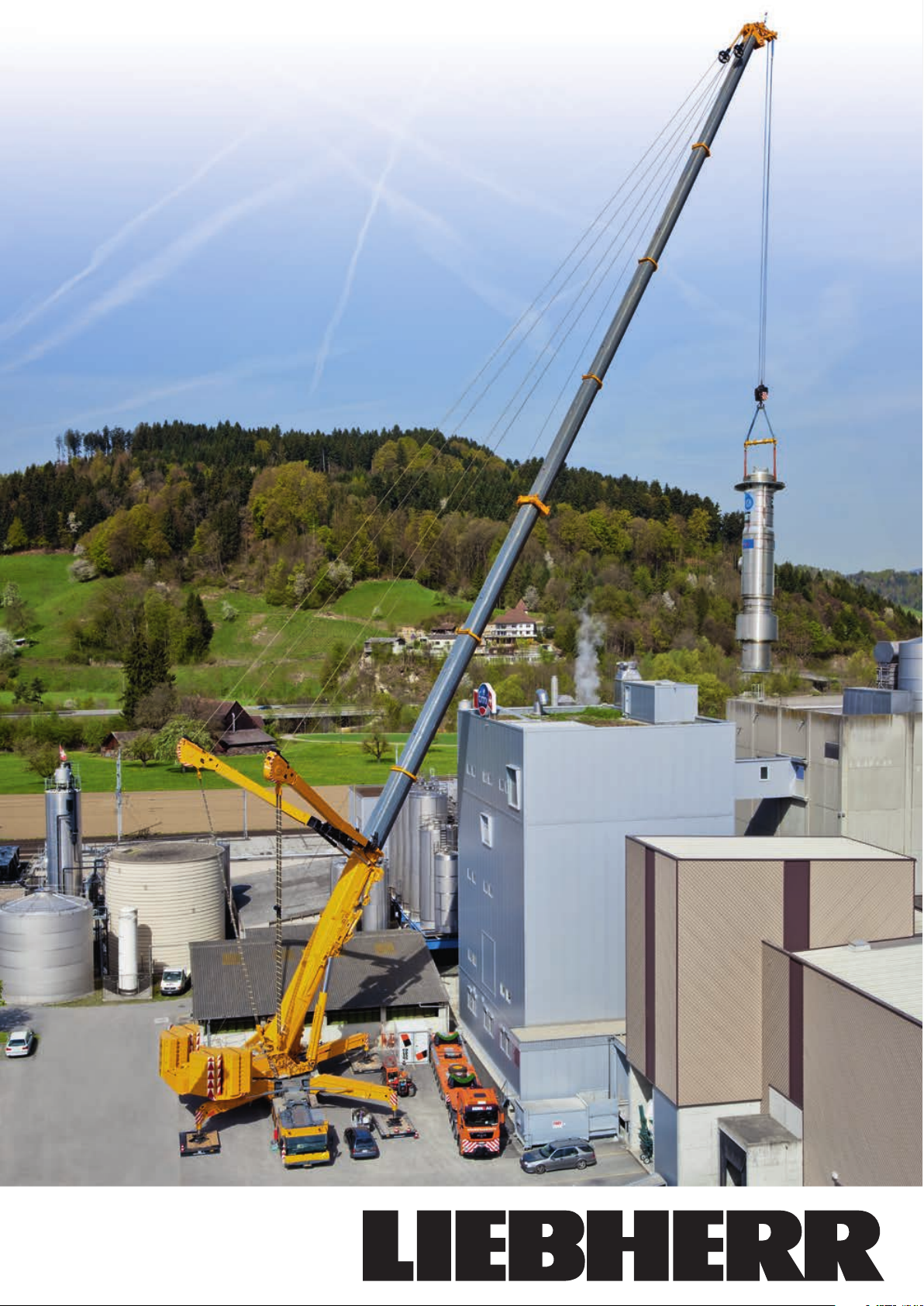
Mobile Crane
LT M 112 0 0 - 9
Max. Capacity: 1,200 t
Max. Hoisting height: 188 m
Max. Radius: 136 m
.1
Page 2
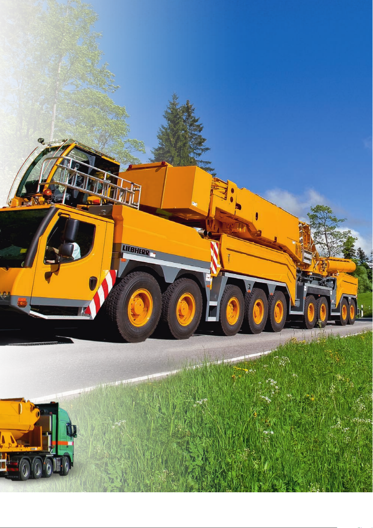
Mobile Crane LTM 11200-9.1
With maximum capacity
universally useable
2
LT M 11 20 0- 9.1
Page 3
The LTM 11200-9.1 with its capacity of 1,200 t is the strongest telescopic mobile crane in the market
and offers the worldwide longest telescopic boom. A remarkable increase of the capacity is realized
with the Y-telescopic boom suspension. Short erection times, an extraordinary mobility as well as a
comprehensive comfort and safety configuration distinguish the mobile crane LTM 11200-9.1 from
Liebherr.
• 100 m long telescopic boom and 22 m telescopic boom extension (10 m + 6 m + 6 m)
• Capacity 65 t at the 100 m long, suspended telescopic boom
• 126 m long luffing fly jib
• 60.5 m long fixed jib, optionally hydraulically adjustable
• Fast and comfortable erection with marginal required space
• Optimal for assemblies in the industry, in the wind power generation field and at
infrastructure projects
• Active, speed depending rear axle steering, all axles steered
• Economical transportation
LT M 11 20 0- 9.1
3
Page 4
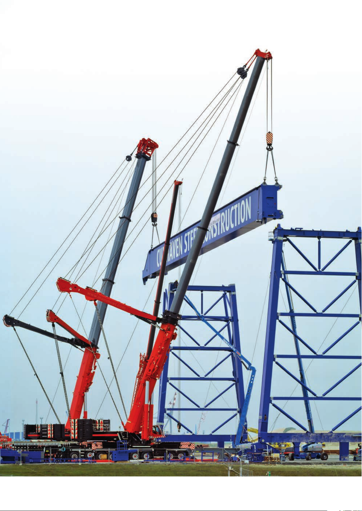
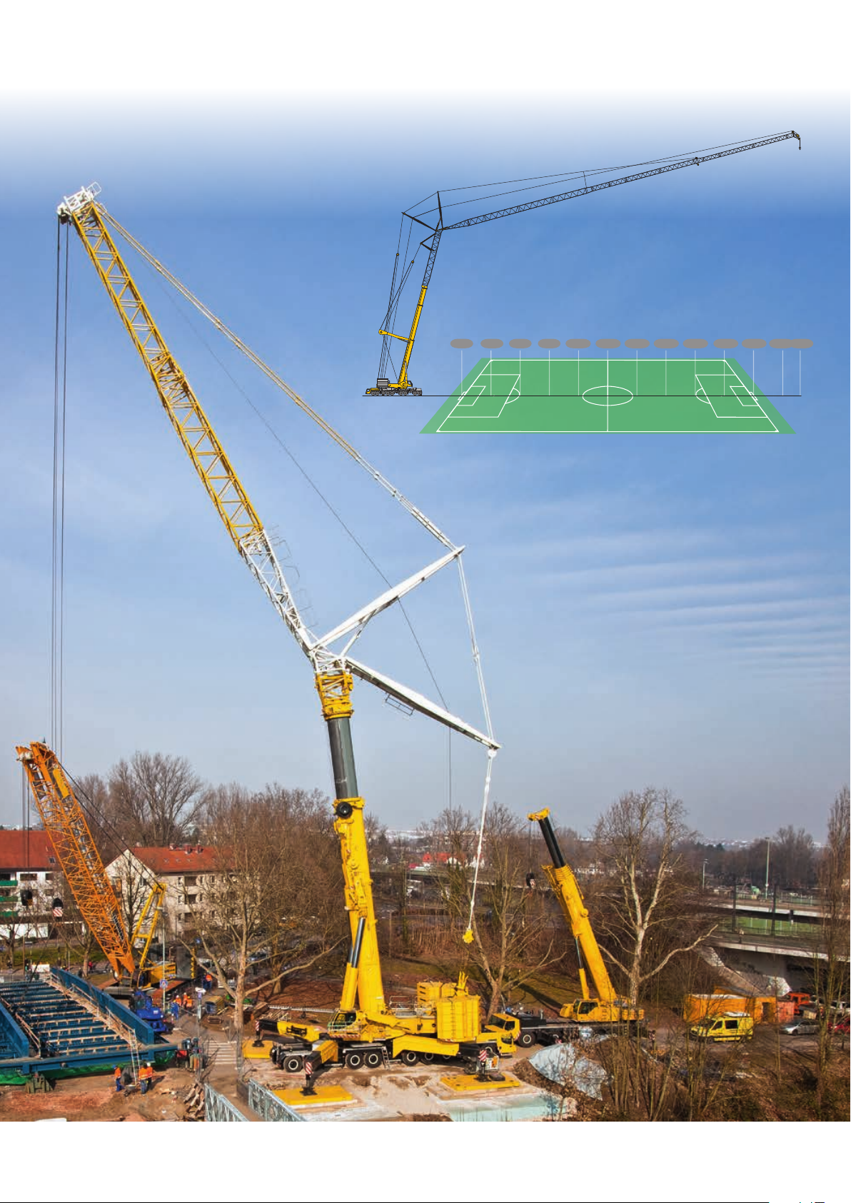
Large operation spectrum with high
performance and variable boom systems
Erection of a portal crane
Load 129.5 t each crane at
max. 21 m radius
Cra n e 1:
System T3Y
Telescopic boom 55 m + Y-suspension
Crane 2:
System T7Y
Telescopic boom 53.3 m +
Y-suspension
4
LT M 11 20 0- 9.1
Page 5
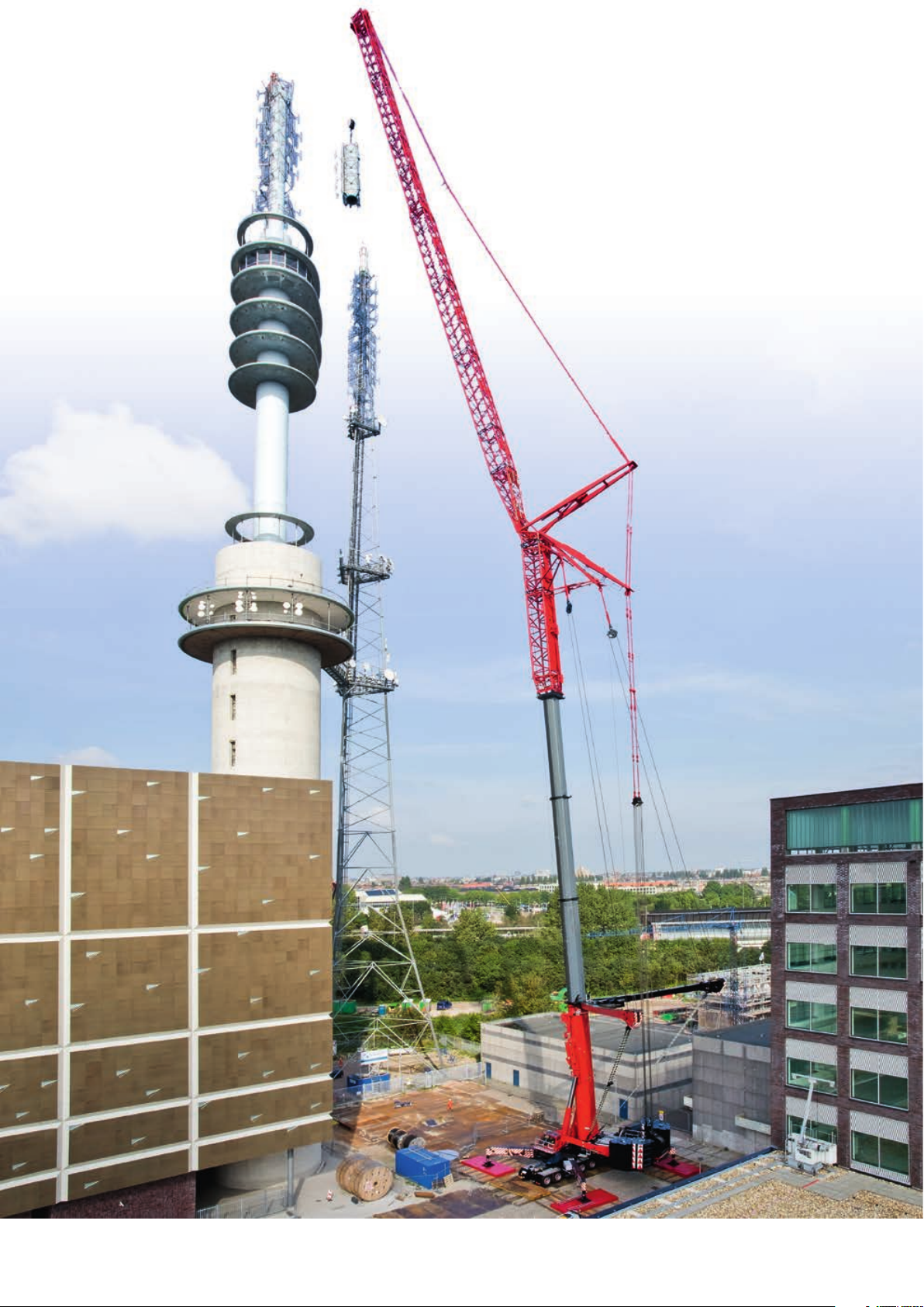
Erection of a radio tower
Load 9.5 t to 154 m hoisting height at
31 m radi us
System T3YV2VEN
Telescopic boom 52.2 m + Y-suspension +
adapter 20.2 m + luffing fly jib 90 m
LT M 11 20 0- 9.1
5
Page 6
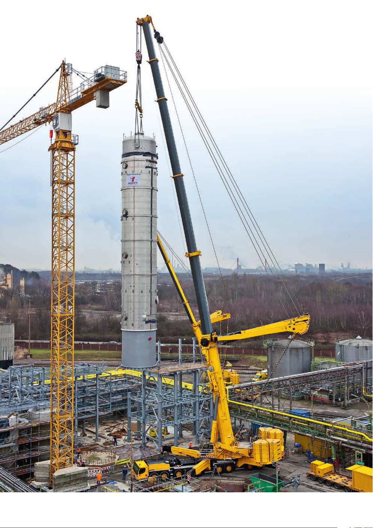
Erection of an
absorber column
Load 128 t at max. 21 m radius
System T7Y
Telescopic boom 65 m + Y-suspension
6
LT M 11 20 0- 9.1
Page 7
Outstanding capacities
at large radii with luffing fly jib
152 t 104 t 74 t 9,9 t 7,1 t59 t 46,5 t 36,5 t 26,2 t 20,3 t 14,3 t 2,1 t3,4 t
706050403020100 120 130 136 m1101009080
LT M 11 20 0- 9.1
7
Page 8
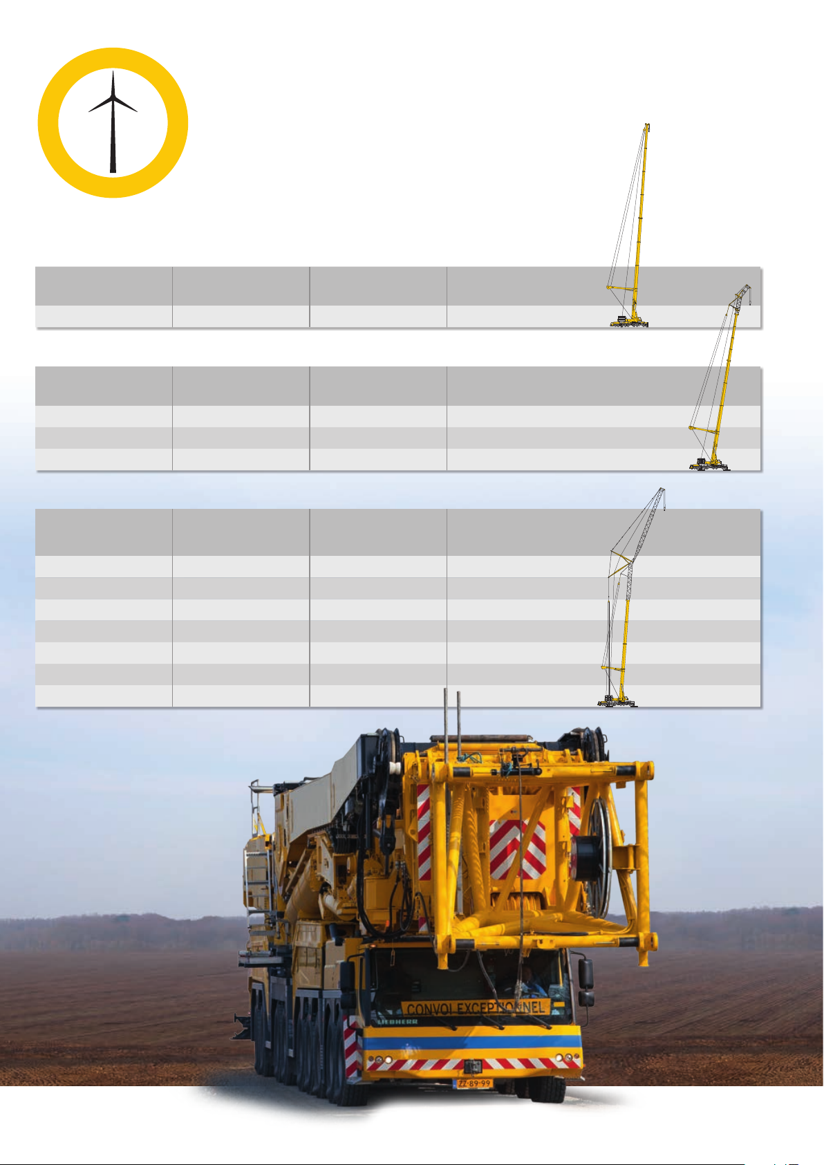
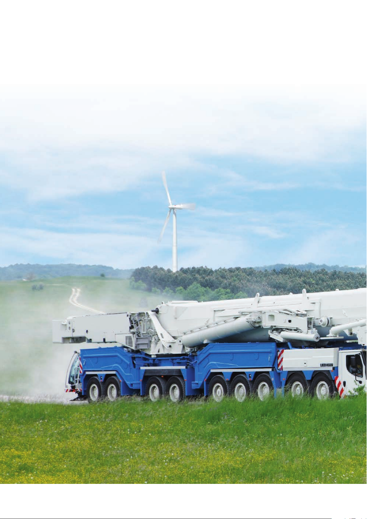
Optimized for the installation
of wind power generators
100 m-telescopic boom + Y-guying system
Height of hub of wind
power generator
80 m 84 t x 16 m 92 m T7Y
100 m-telescopic boom + Y-guying system + fixed jib
Height of hub of wind
power generator
80 m 94 t x 20 m 89 m T7YVENZF
100 m 76 t x 16 m 107 m T7YVEV2NZF
105 m 65 t x 16 m 114 m T7YVEV3V2NZF
52 m-telescopic boom + Y-guying system + luffing jib
Height of hub of wind
power generator
80 m 141 t x 18 m 90 m T3YVEN
100 m 97 t x 22 m 112 m T3YV2VEN
105 m 83 t x 24 m 117 m T3YV2VEN
120 m 58 t x 32 m 128 m T3Y V2VEN
130 m 38 t x 36 m 138 m T3Y V2VEN
140 m 26.1 t x 44 m 148 m T3YV2VEN
150 m 15.8 t x 50 m 158 m T3YV2VEN
Max. capacity
at radius
Max. capacity
at radius
Max. capacity
at radius
Hook height System
Hook height System
Hook height System
8
LT M 11 20 0- 9.1
Page 9

LT M 11 20 0- 9.1
9
Page 10

Economical transportation
The chassis drives on the road with
slewing platform, luffing cylinder and all
four folding beams.
The chassis weight and the axle loads
can further be reduced by dismantling
of equipment components.
Vehicle without telescopic boom 12 t 12 t 108 t
Vehicle without telescopic boom,
without winches
Vehicle without telescopic boom,
without winches, without swingout beams
Axle 1-2 Axle 3-9 Total weight
< 10 t < 12 t < 100 t
< 9 t < 9 t < 76 t
The boom is transported separately on a low bed trailer. For this different variations are possible.
Variable boom transportation concept (examples)
34 t
Heel section + telescope 1
52 t
52 m telescopic boom
77 t
52 m telescopic boom + Y-suspension
75 t
100 m telescopic boom
10 0 t
100 m telescopic boom + Y-suspension
Stated weights without boom lifting unit
10
LT M 11 20 0- 9.1
Page 11
LT M 11 20 0- 9.1
11
Page 12

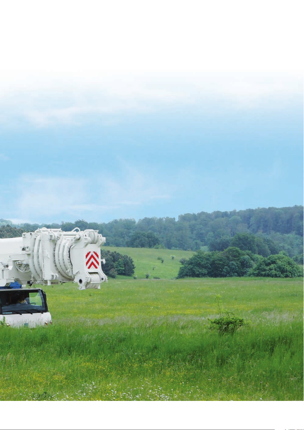
Flexible driving
on the job site
The LTM 11200-9.1 can drive on the job site with the
better part of its equipment on board.
• Reduction of mobilisation times
• Driving inside of a width of 3 m
• Safe driving due to a low centre of gravity
• Boom assembly outside of the job site at limited
site space
Simple and speedy boom assembly
12
LT M 11 20 0- 9.1
Page 13

The assembly of the boom on the job site
can optionally be carried out without an auxiliary crane. By means of four special support jacks the boom is lifted so that the low
bed trailer can move off and the chassis of
the LTM 11200-9.1 can be positioned below
the boom to the front or the rear. The boom
can now be mounted to the chassis with a
few manual actions.
LT M 11 20 0- 9.1
13
Page 14

Economical crane
assignment logistic
A multitude of heavy duty crane operations can be performed with a small number of transportation vehicles.
For the erection of a wind power plant with a hub height
of 80 m and a component weight of up to 80 t for example
only four transportation units are necessary:
Crane LTM 11200-9.1 – self propelled
Transport of telescopic boom T7 – 100 m
Transport of the Y-suspension plus 30 t ballast
Transport of 52 t ballast incl. base plate
14
LT M 11 20 0- 9.1
Page 15

65
Y
360°
54
55
57
82 t
EN
35
22,5
34,5
T 100 m
35
21,2
21,7
T 94,2 m
T 88,3 m
5,5
7,3
2,6
3,8
100 m
T 100 m
T 94,2 m
T 88,3 m
T7
84
97
7,6
4,0
86°
0 4 8 12 16 20 24 28 32 36 40 44 48 52 56 60 64 68 72 76 m
S2528
108 m
104
100
96
92
88
84
80
76
72
68
64
60
56
52
48
44
40
36
32
28
24
20
16
12
8
4
0
LT M 11 20 0- 9.1
15
Page 16

Counterweight
The ballast concept of the LTM 11200-9.1 developed by Liebherr offers numerous advantages for
the crane operator.
• Dimensions and weights of the ballast plates are
ideally adapted to the low bed trailers
• Complete ballast assembly without an auxiliary
crane
• High economy due to compatibility of the ballast
weights with those of other large Liebherr cranes
• Comfortable and safe ballasting with the mobile
control and display unit BTT
16
Base plate 22 t
16 identical plates 10 t each 160 t
4 identical plates 5 t each 20 t
Total ballast 202 t
LT M 11 20 0- 9.1
Page 17

The large scale ballast distribution with two
ballast stacks on each side provides by the
low working height for improved safety and
ergonometric working conditions.
Simple pinning of the base plate to the
ballasting device
Self assembly of hoist gear 2
LT M 11 20 0- 9.1
17
Page 18

Chassis and drive technology
Hydro pneumatic axle suspension
„Niveaumatik“
• Maintenance-free suspension cylinders
• Large dimensions to cope with high axle loads
• Spring travel +175/-125 mm
• High side stability at cornering
• Choice of the driving conditions by fixed programmes
Air operated disk brakes
• Higher braking power, better brake control
• Improved track stability
• No brake fading at higher operation temperatures
• Higher service life
• Shorter working times for changing of the brake pads
• Brake pads with wear indication
Intarder and Telma-Eddy current
brake as standard
• No wear, low maintenance system
• Increased safety due to fast activation in milliseconds
• Reduction of operation costs
• High comfort due to braking absolutely without jolts
• Environmentally friendly brake system, no emission
and respirable dust
Chassis engine
• Powerful 8-cylinder turbo diesel engine with
500 kW/680 HP, max. torque 3,000 Nm
• Automated 12-speed-shift system ZF-TC-TRONIC with
torque converter and intarder directly at the gearbox
offers high efficiency and best comfort
• Axle 1, 2, 4 and 5 are driven axles
Superstructure engine
• 6-cylinder Liebherr turbo diesel engine,
270 kW/367 HP, max. torque 1,720 Nm
• Optimized fuel consumption due to electronic engine
management
18
LT M 11 20 0- 9.1
Page 19

Variable steering concept
Active rear axle steering
• Electro hydraulic steering of the rear axles depending
on the speed and the steering angle of the front axle
• Distinct reduction of the tyre wear
• Improvement of the manoeuvrability
• Stabile driving performance
• All 9 axles steerable, no lifting of the middle axles
during crab steering
High safety standards
• Centralizing cylinders for automatic straightening of the rear
axles in case of failure
• Two independent hydraulic circuits with wheel driven and motor
driven hydraulic pumps
• Two independent steering computers
5 steering programmes
• Programme selection by simple push button
• Clear arrangement of the control elements and displays
• Programmes changeable during driving
• Crab steering controlled comfortably by the steering wheel
P1 Road steering
P2 All-wheel steering
P3 Crab steering
P4 Reduced swing out
P5 Independent rear axle steering
LT M 11 20 0- 9.1
19
Page 20

Comfort and functionality
The modern driving cab as well as the movable crane cab offer a comfortable and functional working place. The control elements and displays are arranged according to ergonometric factors. Thus a safe and wear free working is assured.
The driver’s cab
• Corrosion resistant
• All around safety glazing
• Tinted windows
• Heatable and electrically adjustable
outside mirrors
• Air cushioned driver’s seat with lumbar
support
• Engine independent additional heating,
air condition
The crane cab
• Optimized heating and ventilation system,
automatic temperature control, engine
independent additional heating, air
condition
• Extended field of view due to large
screens
• Crane driver seat with lumbar support,
multiply adjustable
• 20° tiltable to the rear
• Can hydraulically be lowered for a
comfortable access
20
LT M 11 20 0- 9.1
Page 21

Crane supporting –
fast, comfortable and safe
• BTT – Bluetooth Terminal, mobile control and
display device
• Electronic inclination display
• Fully automatic leveling by push button
• Display of supporting forces
• Engine start/stop and speed regulation
• Lighting of the support area with 4 integrated
floodlights
• Stroke of supporting cylinders 750 mm
• Folding beams slewable, 2-fold telescopable
Safe working with
well-thought-out solutions
The supporting, the boom and counterweight assembly
as well as the attachment of additional equipment are designed for speed, safety and comfort. For the safety of the
operating personnel ascents, holding grips and railings
are furnished.
For the observation of the winches and the Y-suspension
in operation mode cameras are installed, which transfer
their pictures to the crane cab. Likewise a back-up camera
system for a safe and comfortable reversing is in place.
LT M 11 20 0- 9.1
21
Page 22

Intelligent
crane control
For functional and safe crane
operation, the LICCON computer
system
The soft- and hardware of the mobile crane control is developed by Liebherr in-house. The centre is the LICCON
computer system (Liebherr Computed Control).
• Integrated LML-load moment limiter
• Key components are in-house manufactured by
Liebherr
• Guaranteed availability of spare parts
• Worldwide proven under the most different climate
conditions
• Operator friendly
The data bus technology
Liebherr mobile cranes are completely interlaced by the
data bus system. All important electric and electronic
components are equipped with own micro processors
and communicate with each other by only limited data
cables. For the special demands of the mobile crane
Liebherr has developed own data bus systems (LSB –
Liebherr-System-Bus). The data bus technology improves
the reliability, the comfort and the safety for road driving
and crane operation:
• Higher reliability due to remarkable less electric cables
and contacts
• Continuous self testing of the „intelligent sensors“
• Comprehensive diagnosis possibilities, fast fault
finding
22
LT M 11 20 0- 9.1
Page 23

BTT-Bluetooth Terminal
For the remote control of crane assembly functions like e.g.
supporting, boom assembly and the ballasting
• Free view and proximity to the assembly work
• Higher comfort and economy
The LICCON work planner
• Computer programme for planning, simulation and
documentation of crane operations at the PC
• Display of all load charts belonging to a specific crane
• Automatic search for the suitable crane by input of the load case
parameters load, radius and hoisting height
• Simulation of crane operations with drawing functions and
display of support forces
LT M 11 20 0- 9.1
23
Page 24

LT M 112 0 0 - 9.1
PN 178 .0 0. E0 2. 2014
Liebherr-Werk Ehingen GmbH
Postfach 1361, 89582 Ehingen, Germany
+49 7391 502-0, Fax +49 7391 502-3399
www.liebherr.com, E-Mail: info.lwe@liebherr.com
www.facebook.com / LiebherrConstruction
The pictures contain als o accessories and speci al equipment not included in the stand ard scop e of delivery. Subjec t to modific ation
 Loading...