

Page 1
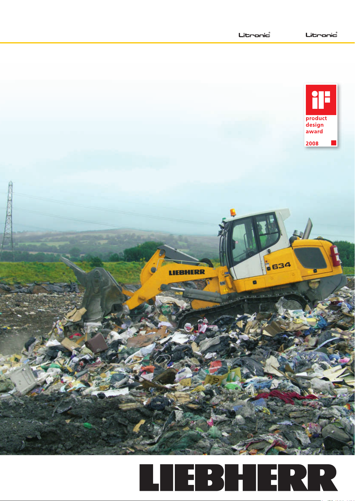
Crawler Loaders
LR 624 LR 634
Product Information
Refuse Loading and
Landfi ll Operation
Page 2
LR 624 Litronic LR 634 Litronic
2
Page 3
Liebherr offers a wide range of additional functions and
equipment for generation IV – crawler loaders.
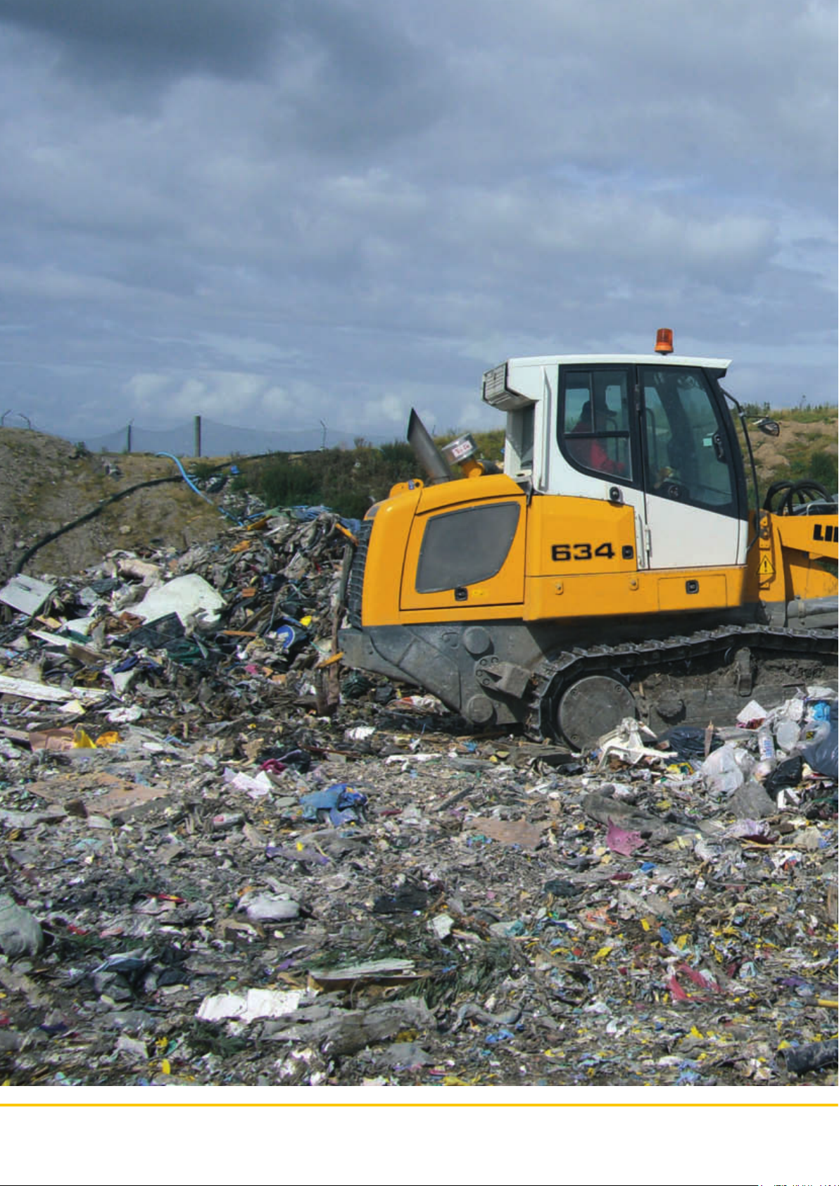
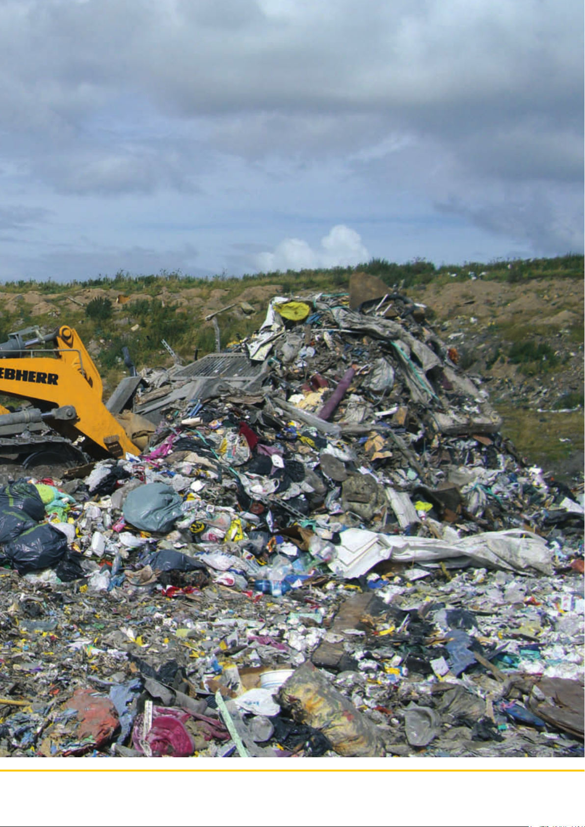
Particularly at waste dumps and waste transfer stations,
the crawler loader becomes indispensable due to its universal operation possibilities. The crawler loader can be
used to shove and condense garbage, and also to load,
sort, break, and reduce material into smaller pieces. In
addition, the crawler loader can be used for many earthmoving purposes at landfi lls, such as refi lling, grading,
carrying material off, and building dams. Even trucks that
get stuck can easily be towed out by a crawler loader.
The Liebherr crawler loader can be individually confi gured with many additional options according to the
purpose of its use, which enables us to provide each
customer with the ideal machine.
The specifi c components were developed especially for
landfi ll usage and guarantee a high life expectancy of the
base machine even under diffi cult circumstances, such
as aggressive material or heavy pollution. The generation
IV- Liebherr crawler dozers guarantee maximum quality
since they combine the functions of power, reliability,
effi ciency and comfort all in one machine.
LR 624 Litronic LR 634 Litronic
3
Page 4
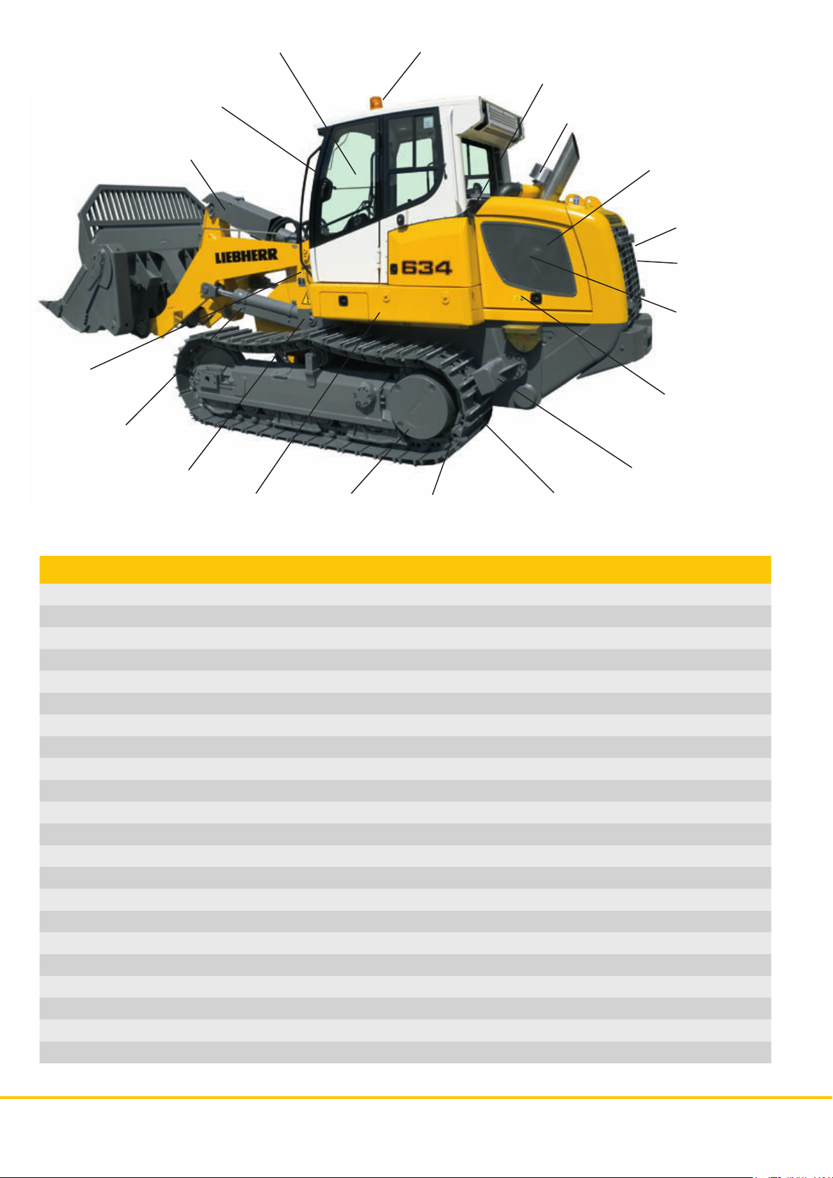
Hydraulic oil indicator Rotating beacon
Protective grille
Sealed ventilation slots
in operator’s cab
Air pre-cleaner engine
Tilt cylinder guard
Filler guard
Lifting cylinder guard
Lift cylinder covers
Tank guard
Protection rings
for fi nal drives
Sprocket segments
with recesses
Fine perforated
plates
Radiator
guard
Reversible fan
Exhaust manifold
isolation
External air
supply alternator
Rear striker bar
Track shoes with
trapezoidal holes
Landfi ll equipment LR 624/LR 634 Standard Recommandation Option
Lift cylinder covers •
Sealed ventilation slots in operator’s cab •
Rear striker bar •
Tank guard •
Track shoes with trapezoidal holes •
External air supply alternator •
Fine perforated plates •
Exhaust manifold isolation •
Radiator guard •
Air pre-cleaner engine •
Reversible fan •
Rear view monitoring camera •
Rotating beacon •
Protection rings for fi nal drives •
Filler guard •
Lifting cylinder guard •
Tilt cylinder guard •
Protective ventilation system •
Protective grille •
Hydraulic oil indicator •
Sprocket segments with recesses •
Central lubrication system •
Subject to technical modifi cations
LR 624 Litronic LR 634 Litronic
4
Page 5

Landfi ll equipment volume
Sealed ventilation slots
in operator’s cab
The front, rear, left and right ventilation slots of the cab are fi tted with
seals to ensure no dirt gets into the
recesses, thus reducing the number
of times cleaning is required.
Lift cylinder covers
The lift cylinders are enclosed
by covers to protect from dirt
and contamination.
Exhaust manifold isolation
The exhaust system is shrouded to
prevent the ignition of dust or waste
particles around the engine, as well
as fl ying sparks.
External air supply alternator
The alternator is provided with pure
cooling air by a hose to guarantee
best cooling results.
LR 624 Litronic LR 634 Litronic
5
Page 6

Landfi ll equipment volume
Protection rings for fi nal drives
The protection rings guarantee
additional protection of the fi nal
drives using a twin lifetime seal
and electronic density control
Radiator guard
A sturdy lateral swivel radiator guard with 45°angled ribs
and a standard skirting protection ensure ideal protection for the rear side and the radiator.
LR 624 Litronic LR 634 Litronic
6
Filler guard
A solid guard reduces the risk of damaging the
diesel fi ller neck. It can be fi tted in combination
with a tank guard.
Page 7

Landfi ll equipment volume
Air pre-cleaner engine
The centrifugal force of the precleaner removes dust particles
before they reach the fi lter. Especially in dust-intensive use,
e.g. at landfi lls, the pre-cleaner
ensures pure air is drawn in. The
system guarantees a longer life
of the fi lter cartridge, reduces
wear and increases the engine’s
life expectancy.
Reversible fan
The reversible fan is benefi cial
in dirt-intense usage due to its
self-cleansing abilities. By reversing the air stream the fan blows
dirt particles off, which increases
the cooling power and reduces
cleaning intervals.
Fine perforated plates
The fi ne perforated plates surrounding the engine prevent intrusion of
dirt particles. Sucked-in material is
blown off by the reversible fan.
Hydraulic oil indicator
The indicator allows monitoring
of the hydraulic oil to prevent
overheating.
LR 624 Litronic LR 634 Litronic
7
Page 8

Front attachments
Strong steel cutter and wear plates provide the necessary longer life guarantee, since they need to resist extremely
corrosive and aggressive material at landfi lls. No matter if used for loading, grading or pushing, all the bucket
versions provide excellent fi lling and penetration attributes.
Standard bucket
The standard bucket is the
most frequently used front
end attachment for crawler
loaders. The shape and
capacity of the bucket has
been designed in a way that
makes it usable for any kind
of material. The standard
bucket is available with an
optional trash rack, which
increases the loading capacity.
Multi purpose bucket
The multi purpose bucket
is a high-performance
multifunctional tool. It can
be used for loading, shoving, grabbing, as well as
grading. The bucket allows
bulky material to be easily
picked up and transported
securely. An optional trash
rack and tilt cylinder protection guard are also available.
Waste handling bucket
The waste handling bucket offers a higher fi lling capacity
and is therefore best suited for material of low weight or
low density. Depending on its specifi c use it is available
with or without teeth.
LR 624 Litronic LR 634 Litronic
8
Page 9

Front attachments
Bolt-on adapters and
teeth segments
create a smooth surface
and increase the bucket
capacity.
Bolt-on adapters
and teeth
provide excellent ground
penetration.
Flush mounted weld-on
adapters and teeth
merge to an even surface
with the main bucket and
provide an excellent fi nish
when levelling.
Bolt-on cutting edges
don’t have as much penetration power, but are
suitable for stockpiling
and clearing tasks.
Bucket options Standard 4in1 Waste handling
bucket bucket bucket
Trash rack • • Standard
Bolt-on adapters and teeth • • •
Bolt-on adapters and teeth segments • •
Flush mounted weld-on adapters and teeth • •
Bolt-on cutting edges • • •
• Optional
Rear attachments
The radial 3-shank ripper provides excellent penetration
and ripping behaviour. At landfi lls, it is mainly used for
loosening the overburden before it is removed to make
room for more waste.
LR 624 Litronic LR 634 Litronic
9
Page 10

Landfi ll equipment options
Tank guard
A 10mm thick protection surrounds
the hydraulic tank and tread-plate
to avoid damage from outside. The
smooth surface prevents objects
from getting entangled.
Track shoes with trapezoidal holes
The trapezoidal holes provide better dispersal of material adhering to
bushings and track shoes.
Rear striker bar
Bars at the rear side optimize the
track’s self-cleaning abilities. In addition, they prevent material from
getting tangled in the chains and
being dragged over the track.
Lifting cylinder guard
The hydraulic pipes of both lifting
cylinders are protected by robust
covers.
Sprocket segments
with recesses
The segment recesses improve
the bushings’ running abilities, as
material on the wearing surface is
automatically pressed through the
lateral openings.
Tilt cylinder guard
The tilt cylinder is protected by a
robust cover that is attached to the
cylinder’s piston.
Protective grille
The windshield, made of safety
glass, is provided with extra protection from falling objects by a
strong metal grille.
LR 624 Litronic LR 634 Litronic
10
Rear view monitoring camera
A display inside the cabin shows
a picture of the area behind the
machine, thus providing the driver
with a detailed rear view and improving comfort.
Page 11

Technical data
Standard bucket
Version with
Nominal rated bucket capacity according to ISO 7546
Nominal rated bucket capacity according to SAE J732
Nominal rated bucket capacity according
to ISO 7546 with trash rack
Nominal rated bucket capacity according
to SAE J732 with trash rack
Breakout force according to ISO 8313
Static tipping load according to ISO 8313
Bucket width, overall
Digging depth, max
Bucket weight
Operating weight ¹
Ground pressure ¹
cu.in
cu.in
cu.in
cu.in
kg/cm²
bolt-on adapters,
segments and teeth
m
m
m
m
kN
kg
mm
ft-in
mm
kg
kg
PSI
3
3
3
3
lb
lb
in
lb
lb
1,8 / 2,4
2.35 / 3.14
1,8 / 2,5
2.35 / 3.27
1,9 / 2,5
2.49 / 3.27
2,0 / 2,6
2.62 / 3.40
127 / 164
28,541 / 36,856
11.765 / 14.148
25,937 / 31,191
2.444 / 2.529
8’0’’ / 8’4’’
136 / 150
5.35’’ / 5.91’’
1.238/ 1.707
2,729 / 3,763
17.006 / 20.914
37,492 / 46,107
0,67 / 0,73
9.53 / 10.38
4 in 1 bucket
Version with
Nominal rated bucket capacity according to ISO 7546
Nominal rated bucket capacity according to SAE J732
Nominal rated bucket capacity according to ISO 7546
with trash rack
Nominal rated bucket capacity according to SAE J732
with trash rack
Breakout force according to ISO 8313
Static tipping load according to ISO 8313
Bucket width, overall
Digging depth, max
Bucket weight
Operating weight ¹
Ground pressure ¹
¹ Machine with ROPS/FOPS cab, coolant and lubricants, full fuel tank, operator (75kg/165lb), bucket without trash rack), rear bumper and track shoes (LR 624 508mm / 20”, LR 634 560mm / 22”)
² If the ripper is mounted, no rear bumper will be fi tted to the machine (weight rear bumper)
cu.in
cu.in
cu.in
cu.in
kg/cm²
bolt-on adapters,
segments and teeth
m
m
m
m
kN
kg
mm
ft-in
mm
kg
kg
PSI
3
3
3
3
lb
lb
in
lb
lb
1,6 / 2,0
2.09 / 2.62
1,6 / 2,1
2.09 / 2.75
1,7 / 2,1
2.22 / 2.75
1,8 / 2,2
2.35 / 2.88
113 / 156
25,394 / 35,058
10.376 / 12.839
22,875 / 28,305
2.448 / 2.529
8’0” / 8’4”
196 / 220
7.72” / 8.66”
1.782 / 2.247
3,929 / 4,954
17.614 / 21.531
38,832 / 47,468
0,70 / 0,75
9.95 / 10.67
LR 624 / LR 634
fl ush mounted weld-on
adapters and teeth
1,7 / 2,3
2.22 / 3.01
1,7 / 2,3
2.22 / 3.01
1,9 / 2,5
2.49 / 3.27
2,0 / 2,6
2.62 / 3.40
138 / 180
31,013 / 40,451
12.011 / 14.514
26,480 / 31,998
2.450 / 2.500
8’0’’ / 8’2’’
111 / 120
4.37’’ / 4.72’’
1.126 / 1.539
2,482 / 3,393
16.849 / 20.746
37,146 / 45,737
0,67 / 0,72
9.53 / 10.24
LR 624 / LR 634
fl ush mounted weld-on
adapters and teeth
1,5 / 1,9
1.96 / 2.49
1,5 / 1,9
1.96 / 2.49
1,7 / 2,1
2.22 / 2.75
1,8 / 2,2
2.35 / 2.88
123 / 169
27,642 / 37,979
10.610 / 13.191
23,391 / 29,081
2.450 / 2.500
8’0” / 8’2”
161 / 190
6.34” / 7.48”
1.671 / 2.080
3,684 / 4,586
17.502 / 21.363
38,585 / 47,097
0,69 / 0,74
9.81 / 10.52
bolt-on
cutting edge
1,8 / 2,4
2.35 / 3.14
1,8 / 2,5
2.35 / 3.27
1,9 / 2,5
2.49 / 3.27
2,0 / 2,6
2.62 / 3.40
127 / 164
28,541 / 36,856
11.863 / 14.268
26,153 / 31,456
2.420 / 2.490
7’11’’ / 8’2’’
136 / 150
5.35’’ / 5.91’’
1.140 / 1.587
2,513 / 3,499
16.908 / 20.794
37,276 / 45,843
0,67 / 0,72
9.53 / 10.24
bolt-on
cutting edge
1,6 / 2,0
2.09 / 2.62
1,6 / 2,1
2.09 / 2.75
1,7 / 2,1
2.22 / 2.75
1,8 / 2,2
2.35 / 2.88
113 / 155
25,394 / 34,833
10.473 / 12.959
23,089 / 28,570
2.420 / 2.490
7’11” / 8’2”
186 / 220
7.32” / 8.66”
1.685 / 2.127
3,715 / 4,689
17.517 / 21.411
38,618 / 47,203
0,69 / 0,75
9.81 / 10.67
LR 624 Litronic LR 634 Litronic
11
Page 12

Technical data
Waste handling bucket LR 624 / LR 634
Version with Trash rack without teeth
Nominal rated bucket capacity according to ISO 7546
for earth
Nominal rated bucket capacity according to SAE J732
for earth
Nominal rated bucket capacity according to ISO 7546
for waste
Nominal rated bucket capacity according to SAE J732
for waste
Breakout force ISO 8313
Static tipping load according ISO 8313
Bucket width, overall
Digging depth, max
Bucket weight
Operating weight ¹
Ground pressure ¹
m
cu.in
m
cu.in
m
cu.in
m
cu.in
kN
kg
mm
ft-in
mm
kg
kg
kg/cm²
PSI
3
3
3
3
lb
lb
in
lb
lb
2,1 / 2,8
2.75 / 3.66
2,1 / 2,8
2.75 / 3.66
3,4 / 4,6
4.45 / 6.02
3,6 / 4,6
4.71 / 6.02
99 / 143
22,248 / 32,136
11.395 / 13.830
25,122 / 30,490
2.736 / 3.000
9’00’’ / 9’10’’
216 / 240
8.5’’ / 9.45’’
1.327 / 1.681
2,926 / 3,706
17.095 / 20.868
37,688 / 46,006
0,68 / 0,73
9.67 / 10.38
3-shank ripper LR 624 / LR 634
radial
Beam width mm 2.096 / 2.100
ft-in 6’11’’ / 6’11’’
Ripping width mm 1.800 / 1.860
ft-in 5’11’’ / 6’1’’
Penetration, max. mm 354 / 390
in 13.94’’ / 15.35’’
Ground clearance, max. below teeth mm 721 / 826
ft-in 2’4’’ / 2’9’’
Additional length, transport position mm 638 / 740
ft-in 2’1’’ / 2’5’’
Ripper weight² kg 935 / 1.163
lb 2,061 / 2,564
Change in operating weight kg 876 / 705
lb 1,931 / 1,554
Change in ground pressure kg/cm2 0,03 / 0,02
PSI 0.43 / 0.28
Change in static tipping load kg 1.460 / 924
lb 3,219 / 2,037
¹ Machine with ROPS/FOPS cab, coolant and lubricants, full fuel tank, operator (75kg/165lb), bucket without trash rack), rear bumper and track shoes (LR 624 508mm / 20”, LR 634 560mm / 22”)
² If the ripper is mounted, no rear bumper will be fi tted to the machine (weight rear bumper)
Printed in Germany by Typodruck BK-RP LWT/VM 10450831-2-09.08
Liebherr-Werk Telfs GmbH
Hans Liebherrstraße 35, A-6410 Telfs
콯 +43 50809 6-100, Fax +43 50809 6-7772
www.liebherr.com, E-Mail: lwt.marketing@liebherr.com
Subject to technical modifi cations.
 Loading...