

Page 1
Technical data
LR 1300 SX
Hydraulic lift crane
Complies with ANSI/ASME B 30.5 1006.01
Page 2
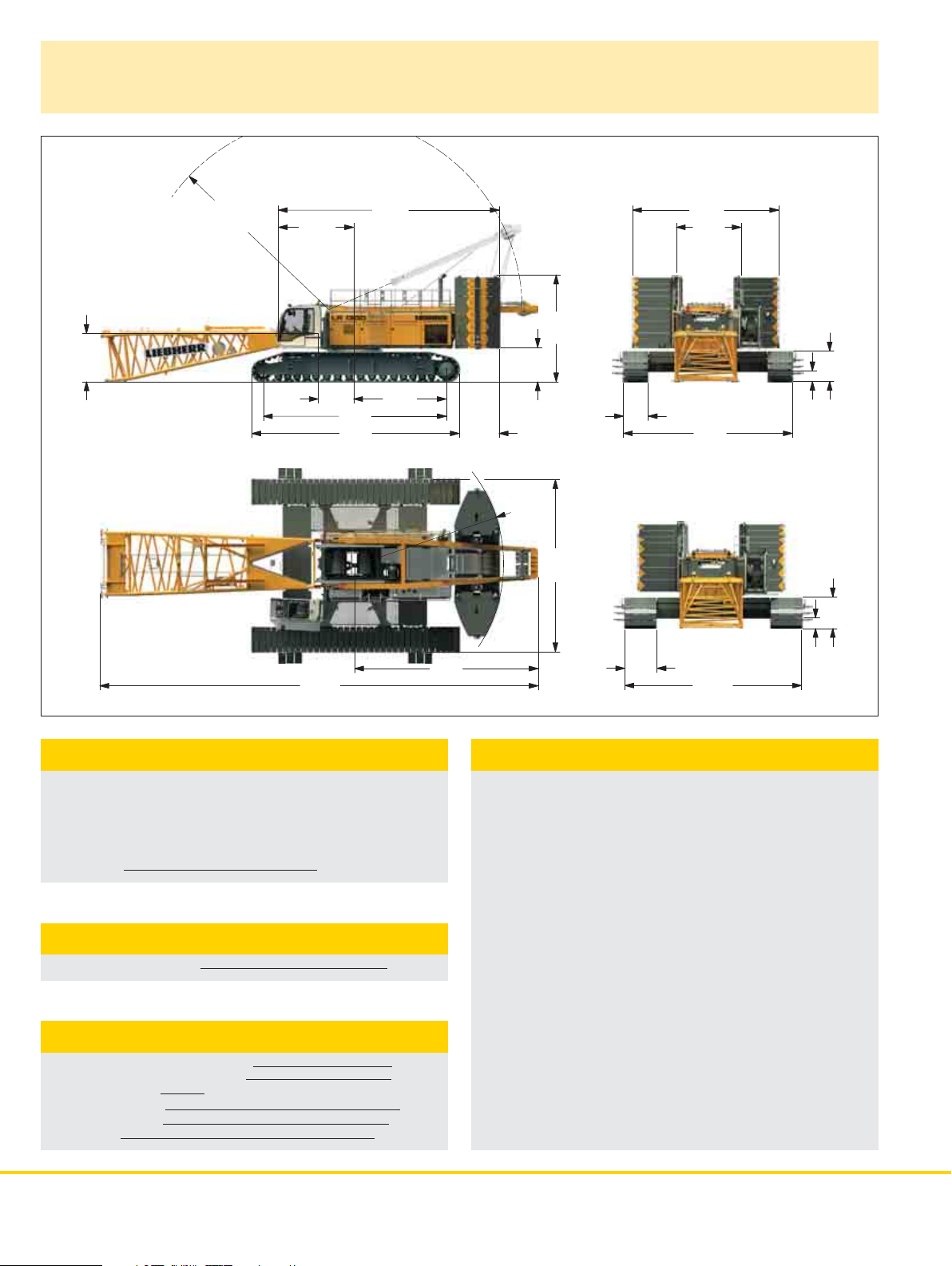
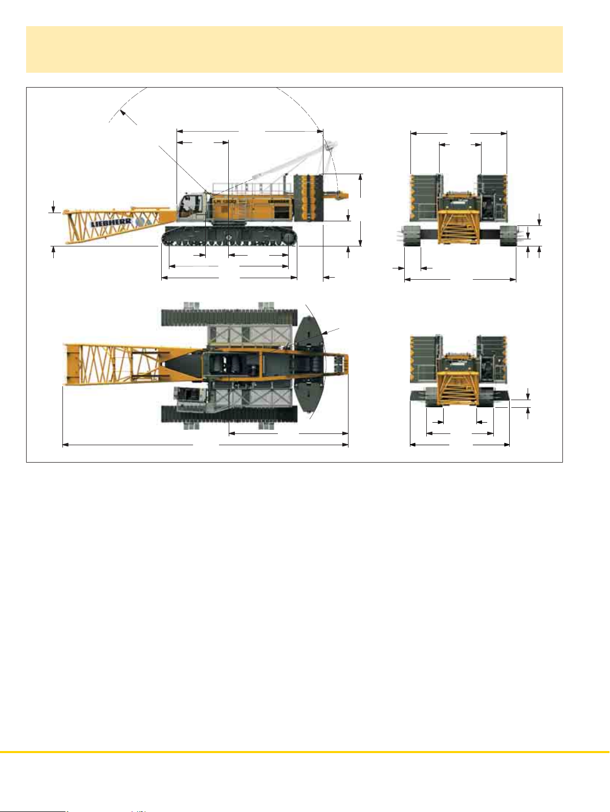
Dimensions
Basic machine with undercarriage
7´5´´
R 32´
11´10´´
5´7´´
27´11´´
31´8´´
34´
14´
6´2´´
5´3´´
R 22´11´´
16´5´´
26´3´´
47.2´´
22´9´´
9´10´´
26´3´´
57.7´´
15.7´´
58.5´´
28´1´´
66´10´´
Operating weight
The operating weight includes the basic machine with crawlers,
2 main winches 33,725 lbf and 66 ft main boom, consisting of
A-frame, boom foot (33 ft), boom head (23 f t), boom extension
(10 ft), 273,400 lbs basic counterweight, 125,700 lbs carbody
conterweight and 661,400 lbs hook block.
Total weight approx. 639,400 lbs
Ground pressure
Ground bearing pressure 20.6 PSI
Equipment
Main boom (No. 2821.xx) max. length 302 ft
Luffing jib (No. 2316.xx) max. length 371 ft
Max. combination main boom 184 ft and luffing jib 371 ft
Fixed jib (No. 0906.xx) 23 ft
Fixed jib (No. 1507.xx) 26.2 ft
Auxiliary jib 79,400 lbs
59´´
27´3´´
15.7´´
Remarks
1. The lifting capacities stated are valid for lif ting operation only
(corresponding with crane classification according to F.E.M.
1.0 01. cra ne g rou p A1).
2. Crane standing on firm, horizontal ground.
3. The weight of the lifting device (hoisting ropes, hook block,
shackle etc.) must be deducted form the gross lifting capacity to
obtain a net lifting value.
4. Additional equipment on boom (e.g. boom walkways, auxiliary jib)
must be deducted to get the net lifting capacity.
5. For max. wind speed please refer to lift chart in operator‘s cab
or manual.
6. Working radii are measured from center of swing and under load.
7. The lifting capacities are valid for 360 degrees of swing.
8. Calculation of stability under load is based on ANSI/ASME B 30.5
load ratings as well as ISO 4305 Table 2 and is tested according
to SAE J765.
9. Loads for calculation of structures are corresponding to F.E.M.
1.001-1998 and are tested according to SAE J987.
2 LR 1300 sx AN SI/ANSE B 3 0.5
Page 3
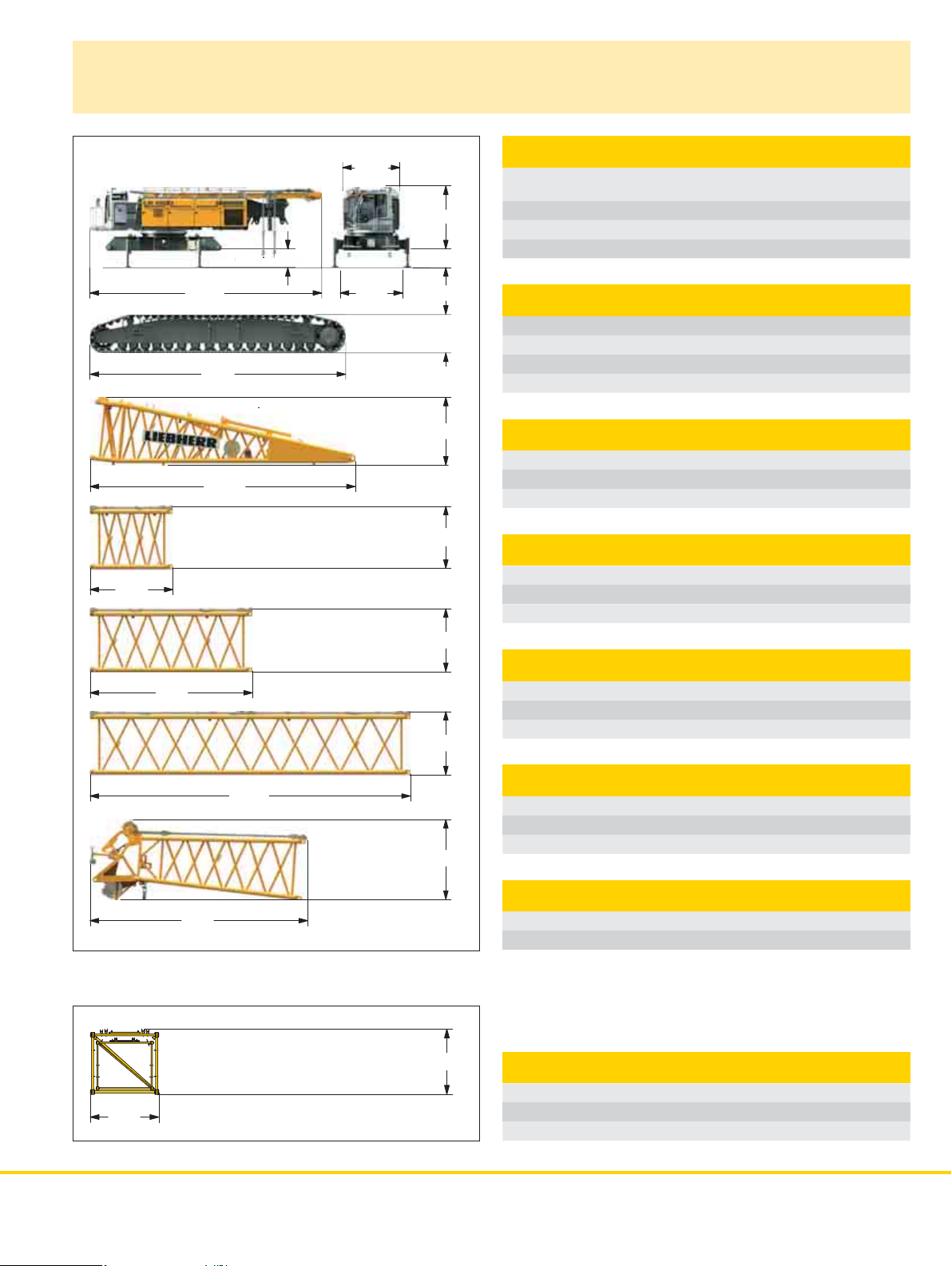
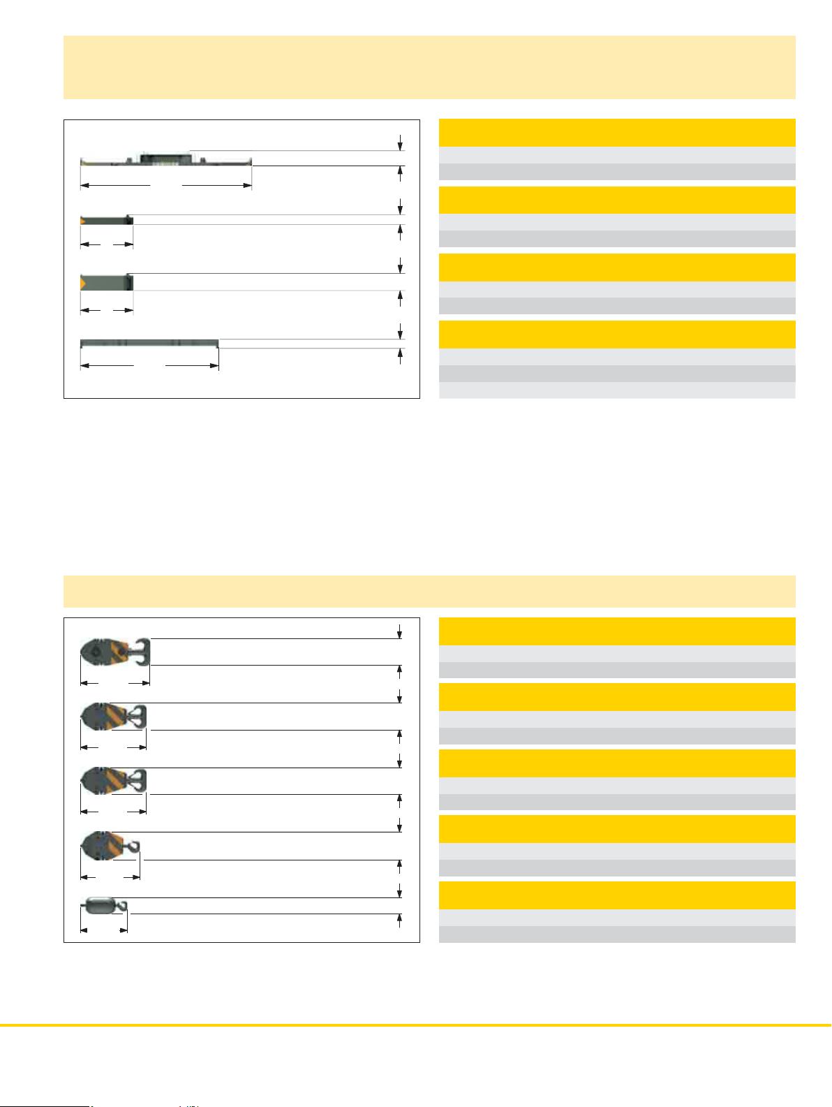
Transport dimensions and weights
Оp
ion
´
Basic machine and boom (No. 2821.xx)
10´8´´
20´6´´
40´
31´8´´
33´10´´
t
55.7´
Оption 55.7´´
9´10´´
11´2´´
10´10´´
38.4´´
57.7´´
8´8´´
8´1´´
8´1´´
8´1´´
Basic machine
with A-frame, 2x 33,725 lbf crane winches, without boom foot, basic
counterweight and crawlers
Width 9´10´´
Weight without hoist rope 101,450 lbs
Weight of hoist rope 2.75 lbs/ft
Crawler 2x
Optional Standard
Flat track shoes 59 inch 47.2 inch
Width 59 inch 55.1 inch
Weight 57,765 lbs 49,275 lbs
Boom foot (No. 2821.30)
Width 2970 mm
Weight without winch 5700 kg
Weight incl. winch and rope 7400 kg
Boom section (No. 2821.30) 10 f t
Width 9´9´´
Weight incl. main boom pendants 3,090 lbs
Weight incl. main boom and luffing jib pendants 3,310 lbs
Boom section (No. 2821.30) 20 ft
Width 9´9´´
Weight incl. main boom pendants 4,700 lbs
Weight incl. main boom and luffing jib pendants 5,100 lbs
40´2´´
26´11´´
9´9´´
*) Weights depend on the equipment installed
10´2´´
8´1´´
Boom section (No. 2821.30) 40 ft
Width 9´9´´
Weight incl. main boom pendants 8,290 lbs
Weight incl. main boom and luffing jib pendants 9,090 lbs
Boom head (No. 2821.24)
Width 9´9´´
Weight incl. main boom pendants 11,905 lbs
Boom - luffing jib transport option
No. 2821.xx/2316.xx 40/40 20/20 10/10 ft
Length 41´ 20´6´´ 10´8´´
Weight* 13,060 7,200 4,635 kg
LR 1300 sx AN SI/ANSE B 3 0.5 3
Page 4
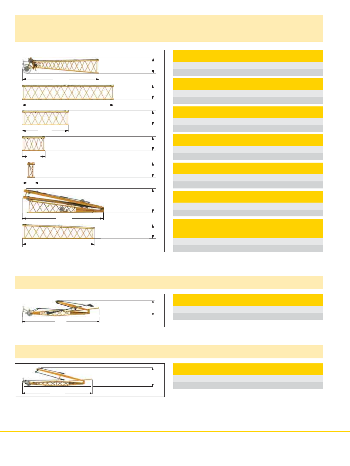
Transport dimensions and weights
Luffing jib (No. 2316.xx)
Luffing jib head (No. 2316.20)
7´2´´
35´3´´
6´3´´
39´10´´
6´3´´
20´2´´
Width 8´
Weight* 5,070 lbs
Luffing jib section (No. 2316.20) 40 ft
Width 8´
Weight* 3.970 lbs
Luffing jib section (No. 2316.20) 20 ft
Width 8´
Weight* 2,100 lbs
10´4´´
45.3´´
38´5´´
40´
Fixed jib (No. 0906.21)
30´2´´
6´3´´
6´7´´
10´10´´
8´1´´
5´11´´
Luffing jib section (No. 2316.20) 10 f t
Width 8´
Weight* 1,325 lbs
L - boom jib section (No. 2316.20) 39.4 inch
Width 8´
Weight* 1,415 lbs
Luffing jib foot with A-frames (No. 2316.22)
Width 8´9´´
Weight* 17,800 lbs
L - boom
section tapered (No. 2821/2316.24) 40 ft
Width 9´9´´
Weight* 5,955 lbs
Fixed jib (No. 0906.21)
Width 59.1 inch
Weight* 5,300 lbs
Fixed jib (No. 1507.20)
33´5´´
*) including carbon fibre pendants
4 LR 1300 sx AN SI/ANSE B 3 0.5
8´11´´
Fixed jib (No. 1507.20)
Width 8´1´´
Weight* 7,275 lbs
Page 5
Transport dimensions and weights
Counterweights
Counterweight 1x
Width 6´11´´
Weight 31,970 lbs
Counterweight 6x
Width 6´11´´
Weight 11,025 lbs
Counterweight 8x
Width 6´11´´
Weight 22,050 lbs
Carbody counterweight 4x
Optional Standard
Width 59.1 inch 47.2 inch
Weight 29,545 lbs 31,420 lbs
22´6´´
7´
7´
18´2´´
(оptional 17´2´´)
24.2´´
15.6´´
26.8´´
13.8´´
Hooks
8´2´´
7´3´´
6´6´´
6´1´´
3´7´´
32.3´´
32.3´´
32.3´´
32.3´´
19.7´´
661,400 lbs hook block – 11 sheaves
Width 34.6 48.4 inch
Weight 7,055 12,125 lbs
330,700 lbs hook block – 5 sheaves
Width 19.7 26.0 32.3 inch
Weight 3,530 6,180 8,820 lbs
220,500 lbs hook block – 3 sheaves
Width 13.4 18.9 24.4 inch
Weight 2,425 4,520 6,620 lbs
110,230 lbs hook block – 1 sheave
Width 11.0 16.1 21.3 inch
Weight 1,765 3,530 5,295 lbs
35,300 lbs single hook
Width 19.7 inch
Weight 1,985 lbs
LR 1300 sx AN SI/ANSE B 3 0.5 5
Page 6
Dimensions (optional)
Basic machine with telescopic undercarriage
7´10´´
R 32´
12´6´´
5´7´´
66´10´´
27´11´´
31´9´´
34´8´´
14´
28´1´´
6´2´´
16´11´´
5´9´´
R 22´11´´
47.2´´
22´9´´
9´10´´
26´3´´
7´10´´
15´9´´
23´4´´
58.1´´
20.5´´
20.5´´
6 LR 1300 sx AN SI/ANSE B 3 0.5
Page 7
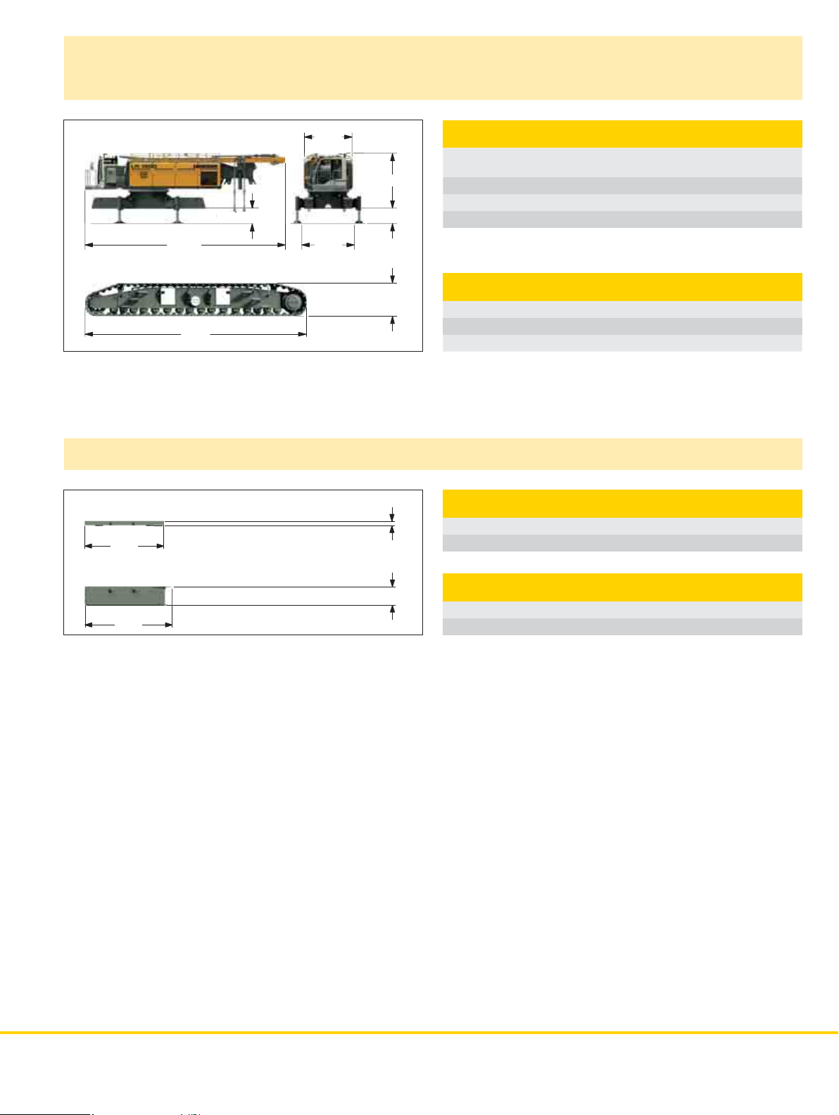
Transport dimensions and weights (optional)
Basic machine
9´10´´
Option 55.7´´
55.7´´
40´4´´
31´9´´
10´9´´
Carbody counterweights (optional)
10´5´´
11´6´´
38.1´´
4´10´´
7.9´´
Basic machine
with A-frame, 2x 33,725 lbf crane winches, without boom foot, basic
counterweight and crawlers
Width 9´10´´
Weight without hoist rope 102,515 lbs
Weight of hoist rope 2.75 lbs/ft
Crawler 2x
Track pads 47.2 inch
Width 47.2 inch
Weight 50,710 lbs
Carbody counterweight 2x
Width 5´11´´
Weight 13,670 lbs
11´7´´
30.3´´
Carbody counterweight 2x
Width 5´11´´
Weight 44,315 lbs
LR 1300 sx AN SI/ANSE B 3 0.5 7
Page 8
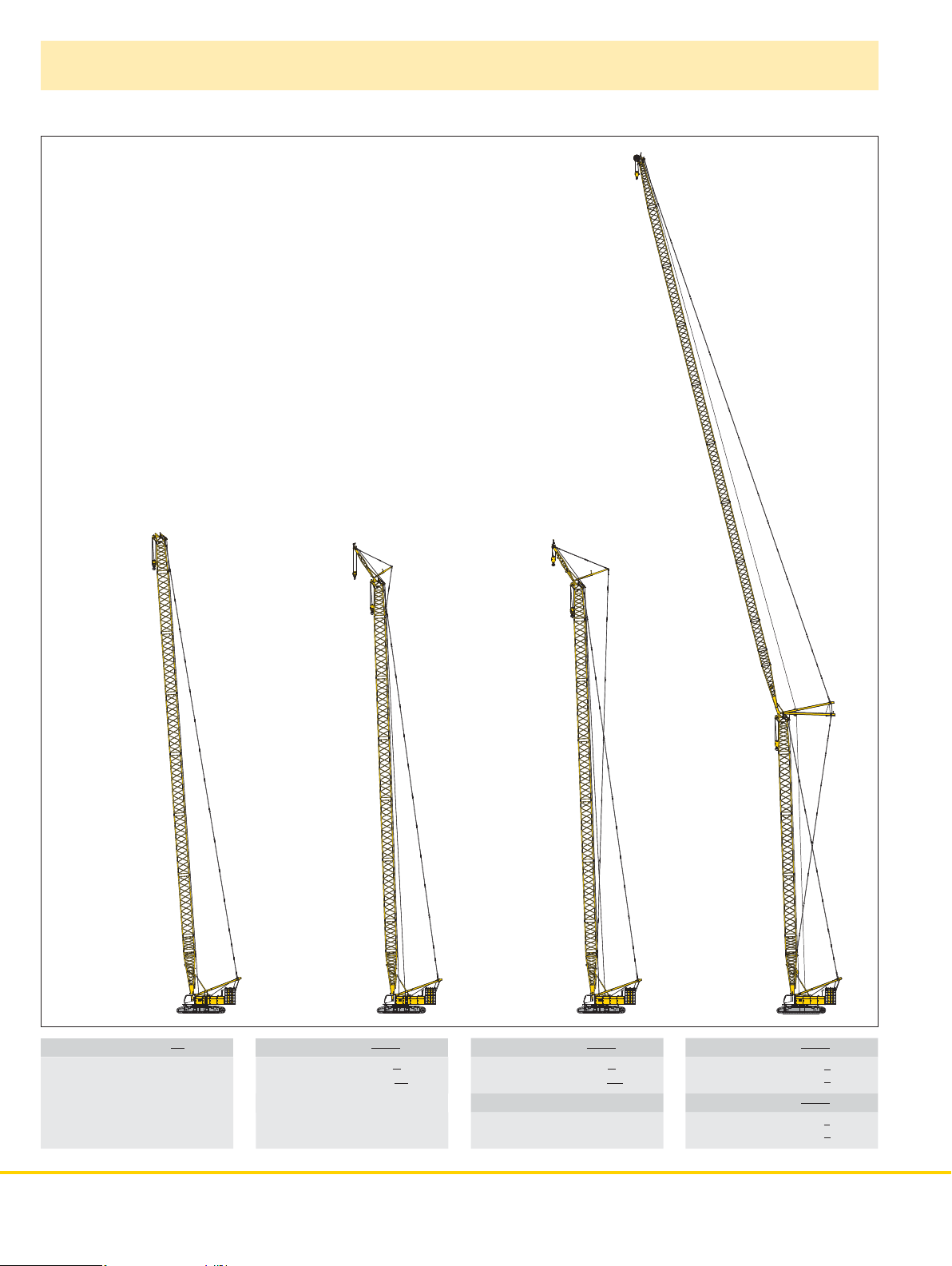
Boom combinations
7 m (23 ft)
No. 2821.24
12 m (40 ft)
No. 2821.30
12 m (40 ft)
No. 2821.30
12 m (40 ft)
No. 2821.30
12 m (40 ft)
No. 2821.30
7 m (23 ft)
No. 0907.21
7 m (23 ft)
No. 2821.24
12 m (40 ft)
No. 2821.30
12 m (40 ft)
No. 2821.30
12 m (40 ft)
No. 2821.30
8 m (26 ft)
No. 1507.20
7 m (23 ft)
No. 2821.24
12 m (40 ft)
No. 2821.30
12 m (40 ft)
No. 2821.30
12 m (40 ft)
No. 2821.30
10 m (32.8 ft)
No. 2316.20
12 m (40 ft)
No. 2316.20
12 m (40 ft)
No. 2316.20
12 m (40 ft)
No. 2316.20
12 m (40 ft)
No. 2316.20
12 m (40 ft)
No. 2316.20
12 m (40 ft)
No. 2316.20
12 m (40 ft)
No. 2316.20
6 m (20 ft)
No. 2316.20
3 m (10 ft)
No. 2316.20
10 m (32.8 ft)
No. 2316.22
7 m (23 ft)
No. 2821.24
12 m (40 ft)
No. 2821.30
12 m (40 ft)
No. 2821.30
12 m (40 ft)
No. 2821.30
3 m (10 ft)
No. 2821.30
10 m (32.8 ft)
No. 2821.30
Main boom No.2821.xx 302 ft
8 LR 1300 sx AN SI/ANSE B 3 0.5
12 m (40 ft)
No. 2821.30
12 m (40 ft)
No. 2821.30
6 m (20 ft)
No. 2821.30
10 m (32.8 ft)
No. 2821.30
Max. combination 295 ft
Main boom
No. 2821.xx 272 ft
Fixed jib No. 0906.21 23 ft
12 m (40 ft)
No. 2821.30
12 m (40 ft)
No. 2821.30
6 m (20 ft)
No. 2821.30
10 m (32.8 ft)
No. 2821.30
Max. combination 298 ft
Main boom
No. 2821.xx 272 ft
Fixed jib No. 1507.21 26 ft
12 m (40 ft)
No. 2821.30
12 m (40 ft)
No. 2821.30
3 m (10 ft)
No. 2821.30
10 m (32.8 ft)
No. 2821.30
Max. combination 555 ft
Main boom
No. 2821.xx 184 ft
Luffing jib No. 2316.xx 371 ft
Max. combination
Main boom
No. 2821.xx 223 ft
348 ft
Luffing jib No. 2316.xx 125 ft
Page 9

Technical description
Engine
Power rating according to ISO 9249, 390 kW (523 hp) at 1900 rpm
Engine type
Fuel tank
indicator and reserve warning
Engine complies with NRMM exhaust certification EPA/CARB Tier 4i
or 97/68 EC Stage IIIB.
Liebherr D 856 A7 SCR
238 gal capacity with continuous level
Hydraulic system
An axial displacement pump supplies the open loop hydraulic
system for boom luffing, jib luffing and travel. The main hoist winches
and swing are operated in a closed loop system. All functions
can be operated simultaneously. To minimize peak pressure an
automatic working pressure cut–off has been installed. All filters are
electronically monitored.
The use of synthetic environmentally friendly (biodegradable) oils is
possible.
Working pressure
Oil tank capacity
max. 5076 PSI
238 gal
Luffing jib winch
Line pull max. 23,605 lbf
Rope diameter
Jib luffing
20 mm
69 sec. from 15° to 78°
Main winches
Line pull (1st layer) max. 48,335 lbf
Line pull (7th layer)
Rope diameter
Drum diameter
Rope speed
Rope capacity in 7 layers
The winches are outstanding in their compact design and easy
assembly.
Propulsion is via a planetary gearbox in an oil bath.
Load support by the hydraulic system; additional safety factor
provided by a spring loaded, multi–disc holding brake.
The main winches use pressure controlled, variable flow hydraulic
motors.
This system features sensors that automatically adjust oil flow to
provide max. winch speed depending on load.
Option – winch with free-fall system:
Line pull (1st layer in crane operation)
Line pull (7th layer in crane operation)
Line pull (1st layer in free-fall operation)
Line pull (7th layer in free-fall operation)
Rope diameter
Drum diameter
Rope speed
Rope capacity in 7 layers
The winches are outstanding in their compact design and easy
assembly.
Clutch and braking functions on the free-fall system are provided by a
compact designed, low wear and maintenance-free multi–disc brake.
33,725 lbf
28 mm
28.7 inch
0 – 453 ft/min
1,870 ft
max. 42,715 lbf
29,225 lbf
38,220 lbf
26,530 lbf
28 mm
28.3 inch
0 – 351 ft/min
1,870 ft
Boom winch
Line pull max. 48,785 lbf
Rope diameter
Boom up
24 mm
127 sec. from 15° to 86°
Crawlers
Propulsion through a xial piston motor, hydraulically released spring
loaded multi–disc brake, crawler tracks, hydraulic chain tensioning
device.
Track pads 47.2 inch (optional 59 inch)
Drive speed
0 – 0.8 mph
Swing
Consists of rollerbearing with external teeth, swing drive with fixed
axial piston hydraulic motor, spring loaded and hydraulically released
multi–disc holding brake, planetary gearbox and pinion.
Both swing modes are possible – speed control or free swing.
A multi– disc holding brake acts automatically at zero swing motion.
Swing speed from 0 – 1.8 rpm continuously variable.
Control
The control system – developed and manufactured by Liebherr – is
designed to withstand extreme environmental conditions such as
temperature, vibration and electromagnetic interference and to meet
all requirements that are needed in heavy duty crane operation.
Complete machine operating data are shown on a high resolution
display. Standard operational information is displayed by means of
graphical symbols, fault indications are displayed in plain text (more
than 15 languages available).
The cranes are equipped with propor tional control for all main
movements, which can be carried out simultaneously.
The crane is operated with 2 multi–directional joysticks, the right for
winch I and boom, the left for winch II and swing control.
Option:
Bi–directional double T–levers for simultaneous boom and luffing jib
operation.
The crawlers are activated by the two foot pedals. Additionally, hand
levers can be attached to the pedals.
Remote control for assembly of counterweight and boom hinge pins.
Noise emission
Noise emissions correspond with 2000/14/EC directive on noise
emission by equipment used outdoors.
LR 1300 sx AN SI/ANSE B 3 0.5 9
Page 10

Self-assembly system
Unloading of basic machine
Unloading and assembly of crawlers
Unloading and assembly of carbody counterweight
Unloading and assembly of counterweight
Unloading and assembly of boom foot
Unloading and assembly of boom
10 LR 1300 sx ANS I/ANSE B 30 .5
Page 11

Erecting of main boom to working position
Assembly of boom
Reeving of hoist and luffing jib ropes
Erecting of main boom and luffing jib Working position
LR 1300 sx AN SI/ANSE B 3 0.5 11
Page 12

Main boom (No. 2821.xx) 86° – 15°
273,400 lbs counterweight and 125,700 lbs carbody counterweight
m
ft
104
340
320
300
280
260
240
220
200
180
160
140
120
100
100
76 ft
16
66 ft
12
86°
4
8
96
92
88
302 ft
292 ft
56
60°
282 ft
272 ft
52
262 ft
253 ft
243 ft
233 ft
4448
84
80
76
72
68
64
60
56
52
48
44
40
36
32
28
80
24
20
60
16
40
12
20
0
20°
8
4
0
88
40°
30°
15°
76
8084
72
50°
68
6064
223 ft
213 ft
203 ft
194 ft
70°
184 ft
174 ft
323640
164 ft
154 ft
144 ft
134 ft
28
80°
125 ft
115 ft
105 ft
95 ft
85 ft
2024
Auxiliary jib 79,400 lbs
6.6´
The maximum capacity of the
auxiliary jib is 79,400 lbs.
The corresponding load chart
is programmed in the LMI
system.
0 m
180
160
260280
240
200220
120140
100
60
80
40
0 ft
20
Main boom configuration ( No. 2821.xx)
Configuration for boom lengths between 66 f t and 3 02 ft
Length* Amount of boom extensions
Boom foot 33 ft1111111111111111111111111
Boom insert10 ft1111111111111
Boom insert 20 ft 11 11 11 11 11 11
Boom insert 40 ft 1111222233334444555566
Boom head 23 ft1111111111111111111111111
Boom length (ft) 66 76 85 95 105 115 125 134 144 154 164 174 184 194 203 213 223 233 243 253 262 272 282 292 302
*Actual lengths of boom sections are metric (e.g. 3 m, 6 m, 7 m, 10 m, 12 m). The figures shown above are approximate conversions to feet.
12 LR 1300 sx ANSI/ANSE B 30.5
Page 13

Lift chart for main boom (No. 2821.xx)
229,300 lbs counterweight and 125,700 lbs carbody counterweight
Boom length in (ft)
Radius 66 75 85 105 125 144 164 184 203 223 243 262 272 282 Radius
(ft) lbs lbs lbs lbs lbs lbs lbs lbs lbs lbs lbs lbs lbs lbs (ft)
15 662,4 662,4 15
20 578,7 578,3 577,1 574,4 570,0 526,0 20
25 459,0 458,7 457,5 456,4 454,5 453,0 447,4 430,7 369,5 25
30 379,1 378,8 377,7 376,7 374,7 373,3 371,2 369,6 344,9 326,4 291,8 249,7 242,4 227,7 30
40 274,0 274,4 274,2 274,3 273,8 273,4 271,4 269,7 265,7 259,2 252,7 239,8 235,6 222,8 40
50 198,5 198,8 198,6 198,5 197,8 197,3 196,4 195,7 194,7 193,9 190,0 185,4 183,1 180,7 50
60 154,0 154,4 154,1 154,1 153,3 152,6 151,6 150,8 149,7 148,8 147,7 146,4 144,5 142,5 60
70 125,0 124,8 124,8 123,9 123,2 122,1 121,2 120,1 119,1 117,9 116,9 116,3 115,7 70
80 103,9 104,0 103,1 102,4 101,3 100,3 99,1 98,1 96,9 95,8 95,2 94,5 80
90 88,4 87,6 86,9 85,7 84,8 83,5 82,4 81,2 80,0 79,4 78,8 90
105 71,1 70,4 69,8 68,6 67,6 66,4 65,2 63,9 62,8 62,1 61,4 105
125 54,4 53,9 52,8 51,8 50,5 49,4 48,0 46,8 46,2 45,4 125
145 42,5 41,6 40,6 39,3 38,2 36,8 35,6 35,0 34,2 145
165 33,2 32,5 31,2 30,1 28,7 27,5 26,9 26,1 165
185 25,9 24,7 23,7 22,3 21,1 20,5 19,7 185
200 20,7 19,7 18,4 17,2 16,5 15,8 200
220 15,2 13,9 12,8 12,1 11,4 220
240 10,2 9,1 8,5 7,7 240
260 5,9 5,3 4,6 260
270 3,9 3,2 270
275 2,4 275
TLT 10539958 - M107135 Offiziell
Lift chart for main boom (No. 2821.xx)
273,400 lbs counterweight and 125,700 lbs carbody counterweight
Boom length in (ft)
Radius 66 75 85 105 125 144 164 184 203 223 243 262 272 282 292 302 Radius
(ft) lbs lbs lbs lbs lbs lbs lbs lbs lbs lbs lbs lbs lbs lbs lbs lbs (ft)
20,9 480,4 20,9
25 453,8 447,4 430,7 369,5 25
30 398,1 389,6 384,3 379,7 370,3 344,9 326,4 291,8 249,7 242,4 227,7 214,8 30
35 345,3 341,5 338,1 332,7 326,1 322,4 314,7 300,7 278,3 245,7 240,7 227,0 214,8 198,8 35
40 300,7 300,5 299,4 298,4 295,0 291,9 289,2 281,4 274,6 271,7 267,1 239,8 235,6 222,8 210,8 195,5 40
60 174,7 175,1 174,9 174,8 174,0 173,3 172,3 171,5 170,4 169,5 168,4 167,4 166,2 163,9 161,6 155,6 60
70 142,2 142,0 141,9 141,1 140,4 139,3 138,4 137,3 136,3 135,1 134,1 133,5 132,9 132,4 130,9 70
80 118,6 118,6 117,8 117,1 115,9 115,0 113,8 112,8 111,5 110,4 109,8 109,2 108,7 108,1 80
90 101,2 100,4 99,7 98,5 97,5 96,3 95,2 94,0 92,8 92,2 91,6 91,0 90,4 90
105 81,8 81,2 80,5 79,3 78,4 77,1 76,0 74,7 73,5 72,9 72,2 71,6 71,0 105
125 63,2 62,7 61,6 60,6 59,3 58,2 56,9 55,6 55,0 54,3 53,7 53,0 125
145 50,0 49,1 48,1 46,9 45,7 44,4 43,1 42,5 41,7 41,2 40,5 145
165 39,6 38,8 37,6 36,5 35,1 33,9 33,4 32,7 31,9 31,2 165
185 31,6 30,5 29,4 28,1 26,9 26,2 25,5 24,9 24,2 185
200 26,0 25,0 23,7 22,5 21,8 21,1 20,5 19,8 200
220 20,0 18,8 17,6 16,9 16,2 15,6 14,9 220
240 14,6 13,5 12,9 12,1 11,6 10,8 240
260 9,9 9,4 8,4 7,7 6,6 260
270 7,6 6,5 5,8 4,7 270
280 4,6 4,0 2,9 280
285 3,1 285
Above lift chart is for reference only.
For actual lift duty and complete chart with all available configurations please refer to lift chart in operator’s cab or manual.
TLT 10539958 - M107135 Offiziell
LR 1300 sx AN SI/ANSE B 3 0.5 13
Page 14

Working range – luffing jib (No. 2316.xx) 78° – 15°
Main boom 88° – 45°
78°
560
170
70°
73°
76°
520
480
440
400
360
320
280
240
200
160
120
80
40
160
150
140
130
120
110
100
90
80
70
60
50
40
30
20
10
15°
30°
40°
50°
312 ft
302 ft
371 ft
292 ft
282 ft
361 ft
351 ft
272 ft
262 ft
60°
341 ft
331 ft
253 ft
243 ft
322 ft
233 ft
223 ft
213 ft
203 ft
194 ft
184 ft
174 ft
164 ft
154 ft
45°
144 ft
134 ft
125 ft
184 ft
174 ft
115 ft
105 ft
164 ft
154 ft
95 ft
65°
144 ft
134 ft
85 ft
76 ft
125 ft
115 ft
66 ft
105 ft
95 ft
75°
85 ft
76 ft
66 ft
83°
88°
0
0
102030405060708090100110
0 m
40 0 ft80120160200240280320360
Boom configuration for main boom lengths (66 ft – 223 ft) – see table on page 12
Jib configuration for jib lengths (66 ft – 371 ft)
Length* Amount of luffing jib extensions
Luffing jib foot 33 ft11111111111111111111111111111111
Luffing jib insert10 ft1111111111111111
Luffing jib insert 20 ft 11 11 11 11 11 11 11 11
Luffing jib insert 40 ft 1111222233334444555566667777
Luffing jib head 33 ft11111111111111111111111111111111
Luf fing jib length (f t) 66 75 85 95 105 115 125 134 144 154 164 174 184 194 203 213 223 233 243 253 262 272 282 292 302 312 322 331 341 351 361 371
*Actual lengths of boom sections are metric (e.g. 3 m, 6 m, 10 m, 12 m). The figures shown above are approximate conversions to feet.
14 LR 1300 sx ANSI/ANSE B 30.5
Page 15

Lift chart – luffing jib (No. 2316.xx)
Main boom angle 88°
Ma i n b o o m 6 6 f t Mai n b o o m 105 f t
Radius 66 135 174 213 253 292 331 361
(ft) lbs lbs lbs lbs lbs lbs lbs lbs
40,6 207,1
50 168,4 154,6
60 139,4 131,1 128,3 110,3
70 108,3 106,3 103,9 100,4 80,6
75 97,1 97,0 95,3 79,3 55,1
85 84,6 81,1 79,2 75,5 53,9 39,0
90 78,8 75,0 73,7 69,5 52,8 38,5 29,6
120 54,9 53,2 50,3 48,1 46,3 33,9 25,9
140 44,0 43,5 40,0 38,6 36,4 30,6 24,0
180 30,3 29,2 27,8 25,4 23,2 19,9
215 22,3 21,0 18,7 16,1 14,4
255 14,5 13,5 11,1 8,6
290 9,0 7,8 2,8
295 7,2 2,0
330 3,6
Jib length in (ft)
Radius 66 135 184 213 253 292 331 371
(ft) lbs lbs lbs lbs lbs lbs lbs lbs
40 258,0
50 231,5 194,6
55 210,8 185,3 134,6
60 185,0 175,2 132,9 102,9
70 138,9 151,0 128,5 100,1 75,6
75 113,5 140,2 125,7 98,5 74,7 50,4
85 121,4 116,9 94,6 72,5 49,8 37,1
95 106,0 102,4 90,0 69,9 48,5 36,3 26,2
140 54,5 63,7 60,8 59,2 42,7 30,4 21,8
190 34,1 39,4 39,3 35,6 25,9 18,3
215 28,0 31,5 30,7 24,3 17,0
255 19,6 22,4 19,2 14,9
295 12,0 14,1 5,1
310 11,1 2,1
330 7,0
Main boom 134 ft Main boom 184 ft
Radius 66 135 174 213 253 292 331 371
(ft) lbs lbs lbs lbs lbs lbs lbs lbs
28,7 258,0
45 245,7 185,5
55 207,6 178,3 133,9
60 186,8 170,0 131,6 96,4
70 147,5 151,3 126,3 94,5 70,4
80 130,9 121,2 91,2 69,1 50,7
85 121,5 114,6 89,3 68,3 50,2 35,9
95 106,0 104,1 86,1 66,2 48,4 35,4 25,2
140 57,6 64,8 61,6 58,0 42,0 29,8 21,3
180 39,2 44,1 43,8 37,0 26,6 18,4
220 27,6 31,3 30,2 23,9 16,4
255 20,8 22,7 19,6 15,1
295 13,1 14,9 5,3
310 11,9 2,4
330 7,9
Jib length in (ft)
Radius 66 135 174 213 253 292 331 371
(ft) lbs lbs lbs lbs lbs lbs lbs lbs
30,4 255,6
45 227,6 147,6
55 194,1 143,7 108,8
65 166,1 133,9 105,3 81,2
70 154,7 129,2 103,1 80,3 61,0
75 132,8 124,6 101,0 79,1 61,0
90 110,3 92,9 74,6 58,6 45,1 32,9
95 105,3 90,1 73,5 57,5 44,4 32,7 23,4
145 54,5 62,1 57,2 48,7 38,5 27,5 19,6
180 41,0 44,7 42,6 34,8 24,9 17,6
220 28,6 31,8 29,6 22,5 15,8
260 19,0 22,4 18,7 14,0
295 13,4 15,7 5,7
310 12,7 2,8
335 7,6
Jib length in (ft)
Jib length in (ft)
Main boom 194 ft Main boom 213 ft
Radius 66 135 174 213 253 292 331 341
(ft) lbs lbs lbs lbs lbs lbs lbs lbs
30,8 240,6
50 203,7 139,9
55 187,7 136,2 104,5
65 162,3 127,7 101,2 78,5
70 151,4 123,5 99,0 77,8 59,3
80 115,1 94,8 75,3 58,6 44,9
90 106,1 88,9 72,1 57,0 44,5 32,5 29,6
120 79,7 74,0 63,5 51,4 40,8 29,7 27,2
145 55,5 61,5 55,7 47,2 37,8 27,4 25,1
180 41,7 44,5 40,9 33,9 24,8 22,6
220 29,1 31,9 29,0 22,4 20,4
260 19,1 22,7 18,8 17,6
295 13,7 15,4 14,8
335 7,7 8,4
345 6,4
Capacities in 1000 lbs with luffing jib (No. 2316.xx) 273,400 lbs counterweight + 125,700 lbs carbody counterweight. Above lif t char t is for
reference only. For actual lift duty and complete chart with all available configurations please refer to lift chart in operator’s cab or manual.
Jib length in (ft)
Radius 66 135 174
(ft) lbs lbs lbs
31,5 214,0
50 184,6 125,9
55 173,5 122,5 95,9
60 165,4 118,7 95,0
70 145,8 111,6 91,3
80 33,4 104,0 86,9
90 96,8 81,9
100 90,0 77,8
110 83,7 73,2
120 76,9 68,6
140 61,0 60,9
145 56,1 58,9
160 53,6
180 41,9
185 33,4
Jib length in (ft)
Main boom 223 ft
Jib length in (ft)
Radius 125
(ft) lbs
44,1 128,9
50 126,8
60 119,1
70 111,0
80 104,0
90 95,4
95 92,0
100 89,1
105 85,6
110 82,3
115 79,3
120 76,8
125 72,3
130 67,0
135 61,6
TLT 10539958 - M107135 Offiziell
LR 1300 sx AN SI/ANSE B 3 0.5 15
Page 16

Lift chart – luffing jib (No. 2316.xx)
Main boom angle 83°
Ma i n b o o m 6 6 f t Mai n b o o m 105 f t
Radius 66 135 174 213 253 292 331 361
(ft) lbs lbs lbs lbs lbs lbs lbs lbs
37,7 258,0
60 165,7 162,0
70 129,7 128,6 120,9
80 98,6 103,3 103,2
85 94,8 96,0 94,6
95 80,6 79,9 80,0 72,4
105 70,9 69,2 68,3 67,4 49,6
120 59,4 56,6 56,5 55,9 48,0 33,6
125 56,7 54,0 53,2 51,9 47,1 33,3 24,6
145 46,2 44,4 41,9 40,8 38,8 31,0 23,2
185 32,1 30,0 29,0 26,2 25,1 20,2
220 23,6 21,8 19,5 17,2 14,9
260 15,9 14,1 11,8 8,9
300 9,8 7,9
335 4,8
Jib length in (ft)
Radius 66 135 174 213 253 292 331 371
(ft) lbs lbs lbs lbs lbs lbs lbs lbs
42,5 258,0
65 166,5 164,2
75 139,3 137,1 134,7
85 115,2 117,4 116,0
90 109,4 108,0 96,1
100 96,2 94,8 91,9 70,4
110 85,6 84,2 82,8 68,8 47,5
125 73,2 71,9 70,4 65,6 46,1 32,4
135 66,6 65,3 63,9 62,4 44,8 31,5 22,0
150 56,1 57,2 55,8 54,3 42,7 30,0 21,0
190 38,3 40,9 39,5 37,3 26,5 18,3
225 29,1 31,0 29,6 24,1 16,6
265 20,5 22,7 19,5 13,6
305 12,9 14,9 4,2
340 7,8
Main boom 134 ft Main boom 184 ft
Radius 66 135 174 213 253 292 331 371
(ft) lbs lbs lbs lbs lbs lbs lbs lbs
46,1 234,2
70 150,3 147,7
80 127,3 125,0 123,5
85 118,1 116,0 114,5
90 108,1 106,6 92,5
105 89,5 88,1 86,5 66,7
115 80,1 78,7 77,1 65,3 46,3
125 72,3 70,9 69,4 63,5 45,5 31,7
140 62,9 61,6 60,1 58,5 43,5 30,8 21,3
155 55,3 54,2 52,7 51,2 41,7 29,4 20,3
190 41,6 40,3 38,8 37,2 26,5 18,0
230 29,5 29,5 28,0 23,9 16,1
270 20,9 21,5 19,6 13,1
305 14,7 15,8 5,0
345 8,1
Jib length in (ft)
Radius 66 135 174 213 253 292 331 371
(ft) lbs lbs lbs lbs lbs lbs lbs lbs
52,1 195,3
75 135,0 128,3
85 115,7 113,2 104,0
95 100,8 98,7 97,0
100 92,7 91,1 81,0
110 82,5 80,9 77,6 60,1
120 74,2 72,6 71,0 59,1 42,7
130 67,2 65,7 64,1 57,4 42,3 29,6
160 51,8 50,6 49,0 47,4 39,1 27,6 19,4
200 33,4 36,3 34,8 33,1 24,8 17,0
235 28,9 27,5 26,0 22,7 15,5
275 20,9 19,9 18,1 13,2
310 14,6 14,4 5,3
325 12,9 2,5
350 8,5
Jib length in (ft)
Jib length in (ft)
Main boom 194 ft Main boom 213 ft
Radius 66 135 174 213 253 292 331
(ft) lbs lbs lbs lbs lbs lbs lbs
53,3 186,2
75 134,3 123,8
85 115,1 112,5 100,6
95 100,3 98,1 96,2
100 92,1 90,5 78,5
110 82,0 80,4 75,9 58,6
120 73,7 72,1 70,5 57,8 42,2
135 63,8 62,3 60,7 55,6 41,4 29,3
160 51,5 50,2 48,7 47,1 38,7 27,5
200 37,4 36,1 34,5 32,4 24,8
235 28,6 27,2 25,7 22,7
275 21,1 19,7 17,6
315 14,0 13,7
340 10,3
360
Capacities in 1000 lbs with luffing jib (No. 2316.xx) 273,400 lbs counterweight + 125,700 lbs carbody counterweight. Above lif t char t is for
reference only. For actual lift duty and complete chart with all available configurations please refer to lift chart in operator’s cab or manual.
16 L R 1300 sx ANS I/ANSE B 30.5
Jib length in (ft)
Radius 66 135 174
(ft) lbs lbs lbs
55,7 170,9
80 122,7 114,5
90 106,2 102,7 93,0
95 99,3 96,8 91,1
100 90,9 87,0
110 80,9 79,3
120 72,7 71,1
130 65,9 64,4
140 60,1 58,6
150 55,2 53,7
160 50,8 49,5
165 48,8 47,6
180 42,5
190 39,5
200 36,9
Jib length in (ft)
Main boom 223 ft
Jib length in (ft)
Radius 125
(ft) lbs
74,2 116,7
75 116,5
80 113,9
90 101,6
100 90,9
110 80,9
115 76,6
120 72,8
125 69,2
130 66,0
135 63,0
140 60,2
145 57,6
150 55,2
155 53,0
TLT 10539958 - M107135 Offiziell
Page 17

Lift chart – luffing jib (No. 2316.xx)
Main boom angle 75°
Ma i n b o o m 6 6 f t Mai n b o o m 105 f t
Radius 66 135 174 213 253 292 331 361
(ft) lbs lbs lbs lbs lbs lbs lbs lbs
60 181,2
85 117,3 115,1
105 85,0 84,2
120 68,8 68,1 65,1
135 58,9 55,7 55,7 50,2
155 47,1 45,7 43,8 42,7 38,6
170 40,0 37,8 36,3 34,5 28,3
180 36,7 34,6 32,4 32,7 27,6 20,6
195 33,0 31,0 30,0 28,3 25,0 20,1
200 30,7 28,8 26,8 24,3 19,7
230 24,1 22,4 20,1 17,9 15,8
270 16,2 14,2 11,9 10,0
305 10,6 8,3 6,2
345 5,4 3,6
370 2,2
Jib length in (ft)
Radius 66 135 174 213 253 292 331 371
(ft) lbs lbs lbs lbs lbs lbs lbs lbs
70 144,8
95 99,4 96,8
100 93,3 90,9
115 76,6 75,0
130 65,9 64,3 62,7
145 57,6 56,1 54,4 52,8
165 48,9 47,6 46,0 44,3 41,5
180 42,5 40,9 39,3 37,6 27,7
195 38,2 36,7 35,1 33,5 26,9 18,3
205 33,4 34,2 32,7 31,1 26,1 18,1
240 27,3 25,8 24,3 22,6 16,4
280 20,0 18,6 17,0 14,5
315 14,8 13,3 5,2
330 11,9 2,1
355 9,1
Main boom 134 ft Main boom 184 ft
Radius 66 135 174 213 253 292 331 371
(ft) lbs lbs lbs lbs lbs lbs lbs lbs
75 129,1
105 85,5 82,8
120 70,3 68,5
140 58,1 56,4 54,7
155 51,1 49,6 47,9 46,1
170 45,4 44,0 42,3 40,6 38,9
175 33,4 42,4 40,7 39,0 37,3
190 38,0 36,4 34,7 33,1 27,0
205 34,2 32,8 31,2 29,5 26,3 17,5
210 33,1 31,7 30,1 28,4 25,9 17,5
250 24,4 23,0 21,3 19,6 15,7
285 18,3 16,8 15,2 12,7
325 12,8 11,3 4,7
335 10,5 2,6
365 8,2
Jib length in (ft)
Radius 66 135 174 213 253 292 331 371
(ft) lbs lbs lbs lbs lbs lbs lbs lbs
90 97,0
115 72,0 66,4
120 68,2 65,3
135 56,4 54,5
150 49,4 47,6 45,7
165 43,8 42,1 40,2 37,9
185 37,6 36,1 34,4 32,5 29,3
200 32,5 30,9 29,1 26,1 22,9
215 29,4 27,8 26,0 23,3 20,2 16,5
225 27,5 26,0 24,3 21,7 18,7 15,6
260 20,7 19,1 17,0 14,1 11,2
300 14,6 13,1 10,3 7,6
340 9,7 7,4 3,0
345 7,0 2,3
375 4,6
Jib length in (ft)
Jib length in (ft)
Main boom 194 ft Main boom 213 ft
Radius 66 135 174 213 253 292 331
Jib length in (ft)
(ft) lbs lbs lbs lbs lbs lbs lbs
90 95,6
120 67,3 64,1
135 55,4 53,5
155 46,6 44,8 42,9
170 41,4 39,6 37,8 35,1
185 37,0 35,4 33,6 31,3 27,9
190 33,4 34,1 32,4 30,2 26,9
205 30,8 29,1 27,1 24,0 20,8
220 27,8 26,2 24,5 21,4 18,4
225 26,9 25,4 23,6 20,7 17,6
265 19,5 17,9 15,6 12,7
300 14,2 12,4 9,6
340 9,0 6,8
380 3,7
390
Capacities in 1000 lbs with luffing jib (No. 2316.xx) 273,400 lbs counterweight + 125,700 lbs carbody counterweight. Above lif t char t is for
reference only. For actual lift duty and complete chart with all available configurations please refer to lift chart in operator’s cab or manual.
Radius 66 135 174
(ft) lbs lbs lbs
95 86,7
125 62,0 58,7
140 51,0 49,0
150 46,7 44,8
160 43,0 41,2
170 39,8 38,0
180 36,9 35,2
190 34,3 32,7
195 33,1 31,6
200 30,5
210 28,5
215 27,5
220 26,6
225 25,7
230 24,9
Jib length in (ft)
Main boom 223 ft
Jib length in (ft)
Radius 125
(ft) lbs
120,9 60,6
125 58,2
130 55,4
135 52,9
140 50,5
145 48,4
150 46,3
155 44,5
160 42,7
165 41,0
170 39,5
175 38,0
180 36,6
185 35,3
TLT 10539958 - M107135 Offiziell
LR 1300 sx AN SI/ANSE B 3 0.5 17
Page 18

Lift chart – luffing jib (No. 2316.xx)
Main boom angle 65°
Ma i n b o o m 6 6 f t Mai n b o o m 105 f t
Radius 66 135 174 213 253 292 331 361
(ft) lbs lbs lbs lbs lbs lbs lbs lbs
80 122,3
100 93,0
120 70,6
140 53,6 52,9
165 40,6 39,0 38,4
185 32,6 32,4 29,9
205 28,2 26,2 24,6
210 24,9 23,4 21,3
230 21,3 18,9 17,0 14,3
240 19,5 17,1 15,3 13,5
245 16,3 14,4 12,7 9,4
280 12,3 9,8 7,8 6,1
320 6,7 4,4 2,4
325 4,1 2,1
355 2,4
Jib length in (ft)
Radius 66 135 174 213 253 292 331 371
(ft) lbs lbs lbs lbs lbs lbs lbs lbs
95 93,7
115 74,2
135 58,4
155 49,2 47,4
180 40,5 39,0 37,3
185 33,4 37,6 35,9
200 33,8 32,2 30,4
220 29,6 28,1 26,4
225 27,2 25,5 23,8
245 23,9 22,3 20,6 18,8
260 21,7 20,2 18,5 16,8
295 16,1 14,5 12,8 10,5
335 10,9 9,3 5,9
350 8,2 2,4
375 6,2
Main boom 134 ft Main boom 184 ft
Radius 66 135 174 213 253 292 331 371
(ft) lbs lbs lbs lbs lbs lbs lbs lbs
110 74,3
125 63,5
145 50,0
170 40,8 39,0
190 35,2 33,6 31,7
195 34,0 32,5 30,6
215 28,3 26,6 24,8
235 24,8 23,2 21,5 19,6
260 19,7 18,1 16,3 13,8
270 18,5 16,9 15,1 12,7
280 15,8 14,1 11,7 8,8
310 12,8 11,2 9,1 6,4
345 8,5 6,3 3,8
360 5,1 2,0
385 3,3
Jib length in (ft)
Radius 66 135 174 213 253 292 331
(ft) lbs lbs lbs lbs lbs lbs lbs
125,6 55,8
150 44,6
170 34,9
190 30,1 28,2
215 25,3 23,5 21,6
235 20,6 18,7 16,2
255 18,0 16,3 14,0
260 15,7 13,5 10,5
280 13,7 11,7 8,8 5,8
290 12,8 10,9 8,0 5,1
300 10,0 7,3 4,5
320 8,2 5,7 3,1
330 7,4 5,0 2,4
335 4,6 2,0
370 2,2
Jib length in (ft)
Jib length in (ft)
Main boom 194 ft Main boom 213 ft
Radius 66 135 174 213 253 292 331
(ft) lbs lbs lbs lbs lbs lbs lbs
129,8 52,0
155 33,4
170 33,6
195 27,9 26,0
215 24,3 22,5 20,4
220 23,5 21,7 19,8
260 16,5 14,8 12,2 9,1
285 12,4 10,2 7,2 4,2
290 12,0 9,8 6,9 3,9
295 11,5 9,3 6,5 3,6
300 8,9 6,2 3,3
310 8,0 5,4 2,7
315 7,6 5,0 2,4
335 6,0 3,5
355 2,2
Capacities in 1000 lbs with luffing jib (No. 2316.xx) 273,400 lbs counterweight + 125,700 lbs carbody counterweight. Above lif t char t is for
reference only. For actual lift duty and complete chart with all available configurations please refer to lift chart in operator’s cab or manual.
18 L R 1300 sx ANSI/ANSE B 3 0.5
Jib length in (ft)
Radius 66 135 174
(ft) lbs lbs lbs
138,1 45,0
160 37,3
178 29,0
205 23,8 21,8
210 23,0 21,1
220 21,5 19,6
225 20,7 18,9
230 20,0 18,3
235 17,6
240 17,0
245 16,4
250 15,9
255 15,3
260 14,8
265 14,3
Jib length in (ft)
Main boom 223 ft
Jib length in (ft)
Radius 125
(ft) lbs
176,1 28,7
180 27,9
185 26,9
190 25,9
195 25,0
200 24,1
205 23,3
210 22,5
215 21,7
220 21,0
225 20,2
TLT 10539958 - M107135 Offiziell
Page 19

Lift chart – luffing jib (No. 2316.xx)
Main boom angle 45°
Ma i n b o o m 6 6 f t Mai n b o o m 105 f t
Radius 66 135 174 213 253 292 331
Jib length in (ft)
(ft) lbs lbs lbs lbs lbs lbs lbs
115 73,8
170 43,3
185 38,8
225 27,8
235 24,1
260 18,8
265 15,7
300 11,4 9,2
330 6,5 3,7
335 6,1 3,6
360 2,1
Radius 66 135 174 213 253 292 331
(ft) lbs lbs lbs lbs lbs lbs lbs
137,5 53,1
145 49,7
194 31,5
215 27,3
227 23,6
250 20,4
260 17,4
290 14,3
295 12,2
325 9,7 7,9
360 5,2 2,7
365 4,8 2,4
370 2,1
Jib length in (ft)
Main boom 134 ft Main boom 184 ft
Jib length in (ft)
Radius 66 135 174 213 253 292
(ft) lbs lbs lbs lbs lbs lbs
158,4 39,7
165 37,7
215 23,4
235 20,5
249 17,1
270 14,8
280 12,0
310 9,7
315 7,1
345 4,9 2,2
Radius 66 135 174
(ft) lbs lbs lbs
193,2 22,7
195 22,4
200 21,6
250 12,0
260 11,2
270 10,3
285 6,4
295 5,6
300 5,3
305 4,9
Jib length in (ft)
Main boom 194 ft Main boom 213 ft
Radius 66 135 174
(ft) lbs lbs lbs
200,2 19,9
210 18,5
260 9,3
270 8,5
290 4,1
305 3,2
315 2,6
Capacities in 1000 lbs with luffing jib (No. 2316.xx) 273,400 lbs counterweight + 125,700 lbs carbody counterweight. Above lif t char t is for
reference only. For actual lift duty and complete chart with all available configurations please refer to lift chart in operator’s cab or manual.
Jib length in (ft)
Radius 66 135
(ft) lbs lbs
214,1 14,7
220 14,1
225 13,5
275 4,2
280 3,9
285 3,6
290 3,2
Jib length in (ft)
TLT 10539958 - M107135 Offiziell
LR 1300 sx AN SI/ANSE B 3 0.5 19
Page 20

Working range main boom 88° – 30°
Fixed jib
m
ft
104
340
100
320
300
280
260
240
220
200
180
160
140
120
100
96
92
88
84
80
76
72
68
64
60
56
52
48
44
40
36
32
28
80
24
20
60
16
40
12
20
8
4
0
0
88
(No.0906.21)
30°
76
8084
72
offset 30°
50°
40°
68
6064
56
52
272 ft
262 ft
60°
253 ft
243 ft
4448
233 ft
223 ft
213 ft
203 ft
194 ft
184 ft
70°
174 ft
164 ft
323640
154 ft
144 ft
28
134 ft
125 ft
115 ft
105 ft
2024
95 ft
85 ft
80°
16
76 ft
66 ft
88°
0 m
12
4
8
180
160
260280
240
200220
120140
100
60
80
40
0 ft
20
Main boom configuration ( No. 2821.xx)
Configuration for boom lengths between 66 f t and 272 ft
Length Amount of boom extensions
Boom foot 33 ft1111111111111111111111
Boom insert10 ft11111111111
Boom insert20 ft 11 11 11 11 11 1
Boom insert40 ft 1111222233334444555
Boom head 23 ft1111111111111111111111
Boom length (ft) 66 76 85 95 105 115 125 134 144 154 164 174 184 194 203 213 223 233 243 253 262 272
*Actual lengths of boom sections are metric (e.g. 3 m, 6 m, 7 m, 10 m, 12 m). The figures shown above are approximate conversions to feet.
20 LR 1300 sx AN SI/ANSE B 3 0.5
Page 21

Lift chart - fixed jib 7 m (No. 0906.21) offset 30°
273,400 lbs counterweight and 125,700 lbs carbody counterweight
Main boom 66 ft
Radius 23
(ft) lbs
45 142,3
50 135,4
55 128,3
60 123,3
65 119,2
70 115,1
75 111,8
80 109,8
85 108,2
Main boom 144 ft
Radius 23
(ft) lbs
30 184,1
40 169,8
50 157,2
60 148,4
70 139,6
80 118,9
90 101,1
100 87,3
110 76,2
120 67,2
130 59,8
140 53,4
155 45,3
Main boom 85 ft
Radius 23
(ft) lbs
40 157,3
50 143,2
55 137,9
60 131,7
65 126,4
70 122,9
75 119,5
80 116,2
85 111,6
90 103,3
95 95,9
100 89,4
105 83,4
Main boom 164 ft
Radius 23
(ft) lbs
26,6 188,4
30 185,3
40 171,7
50 160,5
60 152,4
70 141,0
80 117,9
90 100,0
100 86,2
120 66,1
140 52,3
160 42,0
175 33,4
Main boom 105 ft
Radius 23
(ft) lbs
40 162,7
50 149,5
60 138,4
70 128,9
80 120,6
85 111,1
90 102,9
95 95,5
100 89,1
105 83,2
110 78,0
115 73,2
120 68,8
Main boom 184 ft
Radius 23
(ft) lbs
27,3 187,3
30 186,5
40 174,1
50 163,5
60 154,2
70 141,1
80 117,1
100 85,2
120 65,3
140 51,3
160 41,0
180 33,1
190 29,8
Main boom 125 ft
Radius 23
(ft) lbs
35 173,8
40 166,8
50 154,4
60 143,4
70 135,2
80 119,7
90 101,9
100 88,1
110 77,1
120 68,0
130 60,5
135 57,2
140 54,0
Main boom 203 ft
Radius 23
(ft) lbs
28 186,2
30 186,2
40 175,9
50 166,1
60 156,7
80 116,1
100 84,1
120 64,1
140 50,1
160 39,8
180 31,9
200 25,6
205 24,2
Main boom 223 ft
Radius 23
(ft) lbs
28,7 185,1
30 185,1
40 176,9
60 155,1
80 115,1
100 83,1
120 63,0
140 49,0
160 38,7
180 30,8
200 24,5
220 19,4
225 18,2
Capacities in 1000 lbs with fixed jib (No. 0906.21) 273,400 lbscounterweight + 125,700 lbs carbody counterweight. Above lift chart is for reference
only. For actual lift duty and complete chart with all available configurations please refer to lift chart in operator’s cab or manual.
Main boom 243 ft
Radius 23
(ft) lbs
29,4 183,8
30 183,8
40 177,2
60 157,7
80 114,1
100 81,9
120 61,8
140 47,7
160 37,4
180 29,5
200 23,2
220 18,1
240 13,8
Main boom 262 ft
Radius 23
(ft) lbs
30 181,7
40 176,6
60 161,7
80 113,2
100 80,9
120 60,7
140 46,5
160 36,2
180 28,3
200 22,1
220 16,9
240 12,7
260 8,9
Main boom 272 ft
Radius 23
(ft) lbs
30,4 180,5
40 176,4
60 161,7
80 112,7
100 80,3
120 60,1
140 45,9
160 35,6
180 27,7
200 21,4
220 16,3
240 12,1
265 7,0
TLT 10539958 - M107135 Offiziell
LR 1300 sx AN SI/ANSE B 3 0.5 21
Page 22

Working range main boom 88° – 30°
Fixed jib
m
ft
104
340
100
320
300
280
260
240
220
200
180
160
140
120
100
96
92
88
84
80
76
72
68
64
60
56
52
48
44
40
36
32
28
80
24
20
60
16
40
12
20
8
4
0
0
88
(No. 1507.20)
30°
76
8084
72
offset 30°
50°
40°
68
6064
56
52
272 ft
262 ft
60°
253 ft
243 ft
4448
233 ft
223 ft
213 ft
203 ft
194 ft
184 ft
70°
174 ft
164 ft
323640
88°
80°
0 m
28
2024
12
16
4
8
180
160
260280
240
200220
120140
100
60
80
40
0 ft
20
Main boom configuration ( No. 2821.xx)
Configuration for boom lengths between 164 ft and 272 ft
Length* Amount of boom extensions
Boom foot 33 ft 111111111111
Boom insert10 ft 111111
Boom insert 20 ft 1 1 1 1 1 1
Boom insert40 ft 233334444555
Boom head 23 ft 111111111111
Boom length (ft) 164 174 184 194 203 213 223 233 243 253 262 272
*Actual lengths of boom sections are metric (e.g. 3 m, 6 m, 7 m, 10 m, 12 m). The figures shown above are approximate conversions to feet.
22 LR 1300 sx ANS I/ANSE B 30.5
Page 23

Lift chart - fixed jib 8 m (No. 1507.20) offset 30°
124 t counterweight and 57 t carbody counterweight
Main boom 164 ft
Radius 26
(ft) lbs
26,2 257,9
30 257,9
40 251,6
50 220,5
60 175,2
70 141,2
80 117,2
90 99,3
100 85,4
120 65,4
140 51,4
160 41,1
175 34,9
Main boom 203 ft
Radius 26
(ft) lbs
27,8 257,9
30 257,9
40 251,4
50 212,0
60 173,8
80 115,3
100 83,2
120 63,2
140 49,1
160 38,8
180 30,9
200 24,6
210 21,9
Radius 26
(ft) lbs
26,7 257,9
30 257,9
40 247,6
50 219,6
60 174,9
70 140,9
80 116,8
100 85,0
120 65,0
140 51,1
160 40,8
180 32,8
185 31,1
Main boom 213 ft
Radius 26
(ft) lbs
28,2 257,9
30 257,9
40 257,9
50 209,6
60 173,4
80 114,9
100 82,8
120 62,7
140 48,7
160 38,4
180 30,5
200 24,2
220 19,0
Main boom 184 ftMain boom 174 ft
Radius 26
(ft) lbs
27,1 257,9
30 257,9
40 246,1
50 217,9
60 174,5
70 140,4
80 116,3
100 84,4
120 64,4
140 50,4
160 40,1
180 32,2
195 27,3
Main boom 223 ft
Radius 26
(ft) lbs
28,6 257,2
30 256,7
40 251,7
60 172,3
80 114,4
100 82,2
120 62,1
140 48,0
160 37,6
180 29,8
200 23,5
220 18,3
225 17,1
Main boom 194 ft
Radius 26
(ft) lbs
27,4 257,9
30 257,9
40 247,6
50 216,5
60 174,1
70 140,0
80 115,8
100 83,9
120 63,8
140 49,8
160 39,5
180 31,6
200 25,3
Main boom 233 ft
Radius 26
(ft) lbs
29 243,6
30 243,6
40 239,2
60 170,7
80 113,9
100 81,6
120 61,5
140 47,4
160 37,0
180 29,2
200 22,9
220 17,7
235 14,4
Main boom 243 ft
Radius 26
(ft) lbs
29,3 223,1
40 217,8
60 167,9
80 113,3
100 81,0
120 60,8
140 46,7
160 36,3
180 28,4
200 22,1
220 17,0
240 12,7
245 11,7
Capacities in 1000 lbs with fixed jib (No. 1507.20) 273,400 lbs counterweight + 125,700 lbs carbody counterweight. Above lift chart is for reference
only. For actual lift duty and complete chart with all available configurations please refer to lift chart in operator’s cab or manual.
Main boom 253 ft
Radius 26
(ft) lbs
29,7 212,7
40 212,7
60 168,8
80 112,9
100 80,5
120 60,3
140 46,2
160 35,8
180 27,9
200 21,6
220 16,5
240 12,2
255 9,3
Main boom 262 ft
Radius 26
(ft) lbs
30,1 196,3
40 193,6
60 165,4
80 112,4
100 80,0
120 59,7
140 45,5
160 35,1
180 27,2
200 20,9
220 15,8
240 11,5
260 7,2
Main boom 272 ft
Radius 26
(ft) lbs
30,4 183,7
40 181,2
60 159,3
80 111,9
100 79,4
120 59,1
140 44,9
160 34,5
180 26,6
200 20,3
220 15,1
240 10,8
270 4,2
TLT 10539958 - M107135 Offiziell
LR 1300 sx AN SI/ANSE B 3 0.5 23
Page 24

Liebherr-Werk Nenzing GmbH
Dr. Hans Liebherr Str. 1, 6710 Nenzing/Austria
Tel.: +43 50809 41–473, Fax: +43 50809 41–499
crawler.crane@liebherr.com, www.liebherr.com
facebook.com/LiebherrConstruction
LR 1300 SX—10563868—02 /2014 Subjec t to chan ge witho ut notic e.
 Loading...