

Page 1
Machine for
LH 80 M
Industrial Applications
litronic
Operating Weight: 76,200 – 78,100 kg
Engine Output: 230 kW / 313 HP
`
Page 2

Technical Data
Engine
Rating per ISO 9249
�������������������������������
Model
���������������������������������
Type
Bore/Stroke
Displacement
Engine operation
������������������������������
Cooling
Air cleaner
����������������������������
Fuel tank
Engine idling
Electrical system
Voltage
Batteries
Alternator
����������������������������
Standard
���������������
�������������������
�����������������
�������������������
��������������������������
������������������������
������������������������
����������������������
���������������������
Hydraulic System
Hydraulic pump
for attachment
and travel drive
Max. flow
Max. pressure
Pump regulation
Hydraulic pump
for swing drive
Max. flow
Max. pressure
Hydraulic tank
Hydraulic system
Hydraulic oil filter
Hydraulic oil cooler
MODE selection
S (Sensitive)
E (ECO)
P (Power)
Tool Control
���������������
����������������������
����������������
�������������������
����������������
����������������������
����������������
����������������������
������������������
������������������
����������������
��������������������
�������������������
������������������������
����������������������
������������������������
Hydraulic Controls
Power distribution
Servo circuit
Attachment and swing
Travel
Additional functions
�������������������������������
Option
�����������������
��������������������������
���������������
230 kW (313 HP) at 1,700 RPM
Liebherr D936 according to level IIIB / Tier 4i
6 cylinder in-line
122/150 mm
10.5 l
4-stroke diesel
Common-Rail
turbo-charged and after-cooled
reduced emissions
water-cooled with integrated motor oil cooler
dry-type air cleaner with pre-cleaner, primary and
safety elements
910 l
sensor controlled
24 V
2 x 170 Ah/12 V
three phase current 28 V/100 A
Liebherr particle filter
two Liebherr variable flow, swashplate pumps
(double construction)
2 x 350 l/min.
350 bar
electro-hydraulic with electronic engine speed sens-
ing regulation, pressure compensation, flow compen-
sation, automatic oil flow optimizer
reversible, variable flow, swashplate pump, closed-
loop circuit
185 l/min.
380 bar
390 l
910 l
2 full flow filters in return line with integrated fine filter
area (5 μm)
cooling system, consisting of a cooling unit for water
and charge air and a 2
with an infinitely variable, thermostatically controlled
fan drive system
adjustment of engine and hydraulic performance via
a mode pre-selector to match application, e.g. for
especially economical and environmentally friendly
operation or for maximum material handling and
heavy-duty jobs
for precision work and lifting through very sensitive
movements
for especially economical and environmentally friendly
operation
for maximum digging power and heavy duty jobs
ten preadjustable pump flows and pressures for add
on tools
via control valves in single block with integrated
safety valves
�������
with hydraulic pilot control and proportional joystick
levers
electroproportional via foot pedal
via switch or electroproportional foot pedals
Liebherr-Proportional-Control, proportionally acting
transmitters on the joysticks for additional hydraulic
functions
nd
cooler for hydraulic oil, each
Swing Drive
�����������������������������
Drive by
Transmission
Swing ring
Swing speed
Swing torque
Holding brake
Option
�����������������������
��������������������������
�����������������������
�����������������������
����������������������
�������������������������������
Operator’s Cab
����������������������������������
Cab
Operator’s seat Standard
Operator’s seat Comfort
�����������������������������
(Option)
Operator’s seat Premium
�����������������������������
(Option)
Control system
Operation and displays
Air-conditioning
Noise emission
ISO 6396
2000/14/EC
���������������������
��������������������
����������������������������
�������������������������
Undercarriage
���������������������������������
Type
��������������������������������
Drive
Travel speed
Driving operation
Axles
Service brake
Holding brake
Stabilization
������������������������
�������������������
��������������������������������
�����������������������
����������������������
������������������������
Liebherr swash plate motor in a closed system with
integrated brake valve
Liebherr planetary reduction gear
Liebherr, sealed single race ball bearing swing ring,
internal teeth
0 – 6.4 RPM stepless
154 kNm
spring applied – pressure released
pedal controlled positioning brake
safety cab structure with individual windscreens or
featuring a slide-in subpart under the ceiling, work
headlights integrated in the ceiling, a door with a side
window (can be opened on both sides), large stowing
and depositing possibilities, shockabsorbing suspen-
sion, sounddamping insulating, tinted laminated
safety glass, separate shades for the sunroof window
and windscreen
���������
air cushioned operator’s seat with headrest, lap belt,
seat heater, manual weight adjustment, adjustable
seat cushion inclination and length and mechanical
lumbar vertebrae support
in addition to operator’s seat standard: lockable hori-
zontal suspension, automatic weight adjustment,
adjustable suspension stiffness, pneumatic lumbar
vertebrae support and passive seat climatisation with
active coal
in addition to operator’s seat comfort: active elec-
tronic weight adjustment (automatic readjustment),
pneumatic low frequency suspension and active seat
climatisation with active coal and ventilator
joysticks with arm consoles and swivel seat
�����������
large high-resolution operating unit, selfexplanatory,
colour display with touchscreen, video-compatible,
numerous setting, control and monitoring options,
e.g. air conditioning control, fuel consumption,
machine and tool parameters
automatic air-conditioning, recirculated air function,
fast de-icing and demisting at the press of a button,
air vents can be operated via a menu; recirculated air
and fresh air filters can be easily replaced and are
accessible from the outside; heating-cooling unit,
designed for extreme out-side temperatures, sensors
for solar radiation, inside and outside temperatures
LpA (inside cab) = 71 dB(A)
LWA (surround noise) = 105 dB(A)
torsion-resistant box design made from high-strength
steel plate, designed for the toughest requirements
variable flow swashplate motor with automatic brake
valve
0 – 10 km/h stepless
automotive driving using accelerator pedal, cruise
control function: storage of variable accelerator pedal
positions
90 t drive axles; manual or automatic hydraulically
controlled front axle oscillation lock
wet, maintenance-free, low backlash multi disc
brakes
wet, maintenance-free multi disc brakes
4-point outriggers
Uppercarriage
���������������������������������
Type
2 LH 80 M Litronic Machine for Industrial Applications
slewing platform made from high-strength steel plate,
designed for the toughest requirements
Attachment
���������������������������������
Type
Hydraulic cylinders
Energy recovering cylinder
Bearings
Lubrication
����������������
����������������������������
�������������������������
high-strength steel plates at highlystressed points for
the toughest requirements. Complex and stable
mountings of attachment and cylinders.
Liebherr cylinders with special seal system. Shock
absorption
��������
Liebherr gas cylinder with special sealing and control
system
sealed, low maintenance
Liebherr full-automatic central lubrication system
(country-dependent)
Page 3
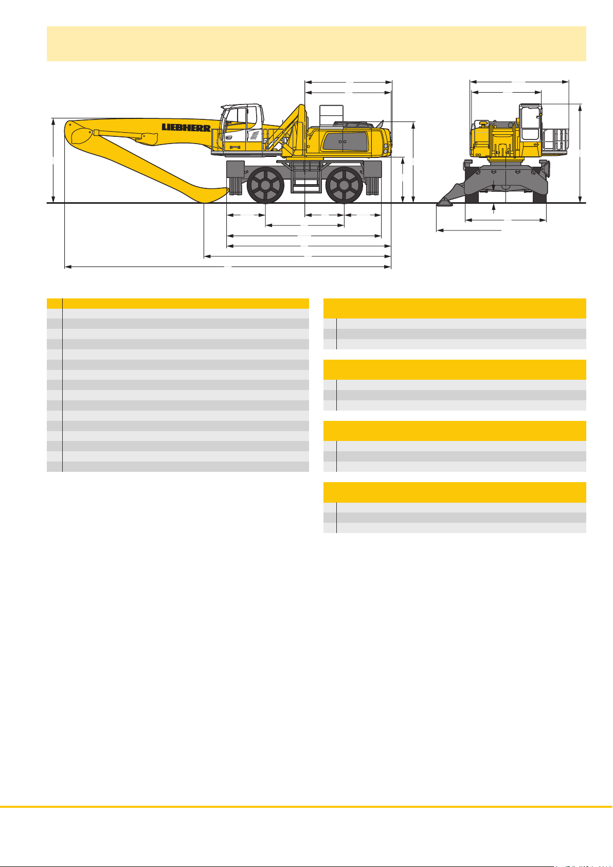
Dimensions
W
T4
X
mm
A 3,190
A1 4,530
B 3,800
B1 6,350
C 4,530
D 3,950
E 3,950
H 3,725
K 2,095
L 3,600
M 1,800
Q 535
T1 1,700
T4 1,775
U4 7,075
Z 7,525
E = Tail radius
Tires 23.5-25
A1
A
Q
B
B1
U4
E
D
H
K
M
L
Z
V
T1
Industrial-Type Straight Mono Boom 10.50 m
and Industrial Stick m 7.80 9.00
V mm 8,550 7,450
W mm 4,100 4,500
X mm 15,150 15,100
Industrial-Type Straight Mono Boom 11.50 m
and Industrial Stick m 9.00 10.00
V mm 8,300 7,600
W mm 4,200 5,300
X mm 16,150 16,050
Industrial-Type Angled Mono Boom 11.50 m
and Industrial Stick m 9.00 10.00
V mm 8,250 7,550
W mm 5,300 5,950
X mm 16,150 16,050
Industrial-Type Straight Mono Boom 12.50 m
and Industrial Stick m 9.00 10.00
V mm 9,100 8,350
W mm 3,850 4,500
X mm 17,100 17,100
C
LH 80 M Litronic Machine for Industrial Applications 3
Page 4

Industrial Attachment
with Industrial-Type Straight Mono Boom 10.50 m
ft m
70
65
60
55
50
45
40
35
30
25
20
15
10
-10
-15
-20
-25
22
20
18
16
14
12
10
8
6
4
2
5
0
0
-5
-2
-4
-6
-8
1
2
3
4
02468101214161820
m
Attachment Envelope
Kinematic variant 2A
1 with industrial stick 7.80 m
2 with industrial stick 9.00 m
3 with industrial stick 7.80 m and grapple model GMM 80-5
4 with industrial stick 9.00 m and grapple model GMM 80-5
Operating Weight
The operating weight includes basic machine with 4 pt. outriggers,
hydr. cab elevation, 4 solid tires and industrial attachment with industrial-type straight mono boom 10.50 m.
with grapple model GMM 80-5/1.70 m
and industrial stick 7.80 m 76,200 kg
and industrial stick 9.00 m 76,700 kg
3
semi-closed tines Weight
65 60 55 50 45 40 35 30 25 20 15 10 5 0
Kinematic Variant 2A
Hole A
ft
2A2A
Hole 2
Energy recovery with
kinematic variant 2A
4 LH 80 M Litronic Machine for Industrial Applications
Page 5
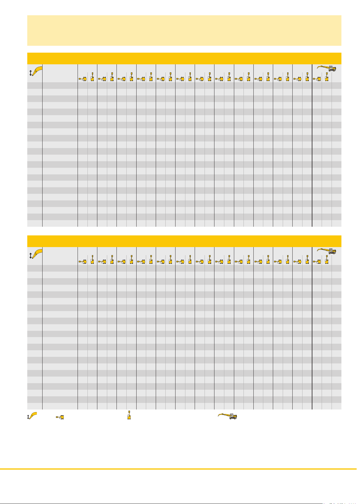
Lift Capacities
with Industrial-Type Straight Mono Boom 10.50 m (Kinematic Variant 2A)
Industrial Stick 7.80 m
4.5 m 6.0 m 7.5 m 9.0 m 10.5 m 12.0 m 13.5 m 15.0 m 16.5 m 18.0 m 19.5 m 21.0 m
m Undercarriage m
Stabilizers raised
24.0
4 pt. outriggers down
Stabilizers raised
22.5
4 pt. outriggers down
Stabilizers raised
21.0
4 pt. outriggers down
Stabilizers raised
19.5
4 pt. outriggers down
Stabilizers raised
18.0
4 pt. outriggers down
Stabilizers raised
16.5
4 pt. outriggers down
Stabilizers raised
15.0
4 pt. outriggers down
Stabilizers raised
13.5
4 pt. outriggers down
Stabilizers raised
12.0
4 pt. outriggers down
Stabilizers raised
10.5
4 pt. outriggers down
Stabilizers raised
9.0
4 pt. outriggers down
Stabilizers raised
7.5
4 pt. outriggers down
Stabilizers raised
6.0
4 pt. outriggers down
Stabilizers raised
4.5
4 pt. outriggers down
Stabilizers raised
3.0
4 pt. outriggers down
Stabilizers raised
1.5
4 pt. outriggers down
Stabilizers raised
0
4 pt. outriggers down
Stabilizers raised
– 1.5
4 pt. outriggers down
Stabilizers raised
– 3.0
4 pt. outriggers down
Stabilizers raised
– 4.5
4 pt. outriggers down
Stabilizers raised
– 6.0
4 pt. outriggers down
Stabilizers raised
– 7.5
4 pt. outriggers down
15.0* 15.0* 13.0* 13.0*
15.0* 15.0* 13.0* 13.0*
14.8* 14.8* 12.6* 12.6* 10.6* 10.6*
14.8* 14.8* 12.6* 12.6* 10.6* 10.6*
15.7* 15.7* 14.4* 14.4* 11.6 12.5* 9.0 9.5*
15.7* 15.7* 14.4* 14.4* 12.5* 12.5* 9.5* 9.5*
15.4* 15.4* 11.9 13.1 9.2 10.2 7.2 8.1
15.4* 15.4* 13.8* 13.8* 12.1* 12.1* 8.8* 8.8*
15.3* 15.3* 11.9 13.2 9.3 10.3 7.3 8.1 6.1 6.8
15.3* 15.3* 13.7* 13.7* 12.5* 12.5* 11.4* 11.4* 8.4* 8.4*
15.4* 15.4* 11.9 13.1 9.3 10.3 7.4 8.2 5.8 6.5 5.3 6.0
15.4* 15.4* 13.8* 13.8* 12.5* 12.5* 11.5* 11.5* 10.0* 10.0* 8.1* 8.1*
17.3* 17.3* 15.1 15.7* 11.6 12.8 9.1 10.1 7.3 8.1 5.8 6.5 4.8 5.4
17.3* 17.3* 15.7* 15.7* 13.9* 13.9* 12.6* 12.6* 11.5* 11.5* 10.6* 10.6* 7.9* 7.9*
18.6* 18.6* 14.6 16.1 11.2 12.4 8.8 9.8 7.1 7.9 5.7 6.4 4.6 5.3 4.3 4.9
18.6* 18.6* 16.1* 16.1* 14.2* 14.2* 12.8* 12.8* 11.6* 11.6* 10.7* 10.7* 9.6* 9.6* 7.9* 7.9*
19.4* 19.4* 18.6 19.5* 13.8 15.3 10.7 11.9 8.5 9.4 6.8 7.7 5.6 6.3 4.6 5.2 4.0 4.6
19.4* 19.4* 19.5* 19.5* 16.7* 16.7* 14.6* 14.6* 13.0* 13.0* 11.8* 11.8* 10.7* 10.7* 9.7 9.8* 7.9* 7.9*
26.3* 26.3* 24.3 25.5* 17.1 19.2 12.9 14.4 10.1 11.2 8.1 9.0 6.6 7.4 5.4 6.1 4.4 5.1 3.8 4.4
26.3* 26.3* 25.5* 25.5* 20.6* 20.6* 17.4* 17.4* 15.1* 15.1* 13.3* 13.3* 12.0* 12.0* 10.8* 10.8* 9.6 9.8* 7.9* 7.9*
19.0* 19.0* 21.5 24.5 15.6 17.5 11.9 13.3 9.4 10.5 7.6 8.5 6.2 7.0 5.2 5.9 4.3 4.9 3.7 4.2
19.0* 19.0* 27.5* 27.5* 21.8* 21.8* 18.1* 18.1* 15.5* 15.5* 13.6* 13.6* 12.1* 12.1* 10.9* 10.9* 9.4 9.7* 8.1* 8.1*
3.9* 3.9* 19.0 20.2* 14.0 16.0 10.9 12.3 8.7 9.9 7.1 8.1 5.9 6.7 5.0 5.6 4.2 4.8 3.6 4.1
3.9* 3.9* 20.2* 20.2* 22.7* 22.7* 18.7* 18.7* 15.9* 15.9* 13.8* 13.8* 12.2* 12.2* 10.7 10.8* 9.3 9.6* 8.1* 8.1*
3.2* 3.2* 10.5* 10.5* 12.8 14.7 10.1 11.5 8.2 9.3 6.7 7.7 5.6 6.4 4.8 5.5 4.1 4.7 3.6 4.1
3.2* 3.2* 10.5* 10.5* 23.2* 23.2* 19.0* 19.0* 16.1* 16.1* 13.9* 13.9* 12.1* 12.1* 10.5 10.7* 9.1 9.2* 7.6* 7.6*
4.0* 4.0* 9.0* 9.0* 12.0 13.8 9.5 10.9 7.7 8.8 6.4 7.3 5.4 6.2 4.6 5.3 4.0 4.6 3.6 4.2
4.0* 4.0* 9.0* 9.0* 20.9* 20.9* 18.8* 18.8* 15.9* 15.9* 13.7* 13.7* 11.9* 11.9* 10.3* 10.3* 8.6* 8.6* 7.0* 7.0*
9.4* 9.4* 11.5 13.3 9.1 10.4 7.4 8.5 6.2 7.1 5.2 6.0 4.5 5.2 3.9 4.5 3.8 4.4
9.4* 9.4* 17.8* 17.8* 18.0* 18.0* 15.3* 15.3* 13.1* 13.1* 11.2* 11.2* 9.5* 9.5* 7.6* 7.6* 6.8* 6.8*
11.3 13.1 8.8 10.2 7.2 8.3 6.0 6.9 5.1 5.9 4.4 5.1 4.3 4.9
17.4* 17.4* 16.3* 16.3* 14.0* 14.0* 11.9* 11.9* 10.1* 10.1* 8.2* 8.2* 7.5* 7.5*
7.2 8.3 6.0 6.9
11.9* 11.9* 10.1* 10.1*
7.0
9.9
11.9
13.4
14.6
15.6
16.3
16.9
17.4
17.7
17.9
17.9
17.8
17.6
17.0
15.5
12.0
Industrial Stick 9.00 m
4.5 m 6.0 m 7.5 m 9.0 m 10.5 m 12.0 m 13.5 m 15.0 m 16.5 m 18.0 m 19.5 m 21.0 m
m Undercarriage m
Stabilizers raised
24.0
4 pt. outriggers down
Stabilizers raised
22.5
4 pt. outriggers down
Stabilizers raised
21.0
4 pt. outriggers down
Stabilizers raised
19.5
4 pt. outriggers down
Stabilizers raised
18.0
4 pt. outriggers down
Stabilizers raised
16.5
4 pt. outriggers down
Stabilizers raised
15.0
4 pt. outriggers down
Stabilizers raised
13.5
4 pt. outriggers down
Stabilizers raised
12.0
4 pt. outriggers down
Stabilizers raised
10.5
4 pt. outriggers down
Stabilizers raised
9.0
4 pt. outriggers down
Stabilizers raised
7.5
4 pt. outriggers down
Stabilizers raised
6.0
4 pt. outriggers down
Stabilizers raised
4.5
4 pt. outriggers down
Stabilizers raised
3.0
4 pt. outriggers down
Stabilizers raised
1.5
4 pt. outriggers down
Stabilizers raised
0
4 pt. outriggers down
Stabilizers raised
– 1.5
4 pt. outriggers down
Stabilizers raised
– 3.0
4 pt. outriggers down
Stabilizers raised
– 4.5
4 pt. outriggers down
Stabilizers raised
– 6.0
4 pt. outriggers down
Stabilizers raised
– 7.5
4 pt. outriggers down
Height Can be slewed through 360° In longitudinal position of undercarriage Max. reach * Limited by hydr. capacity
The lift capacities on the stick end without attachment are stated in metric tons (t) and are valid on a firm, level supporting surface with blocked oscillating axle. These
capacities can be slewed through 360° with the undercarriage in the transverse position. Capacities in the longitudinal position of the undercarriage (+/– 15°) are specified over the steering axle with the stabilizers raised and over the rigid axle with the stabilizers down. Indicated loads comply with the ISO 10567 standard and do not
exceed 75 % of tipping or 87 % of hydraulic capacity. The lift capacity values indicated are attained at the corresponding operating temperature. This operating temperature is ensured by continuous movement of the boom. Weights of fitted working tools (grabs, load hooks, etc.) and load accommodation equipment are to be
deducted from the lift capacity values. The lift capacity of the unit is limited by its stability, the lifting capability of the hydraulic elements, or the maximum permissible
lifting capacity of the load hook.
In accordance with the harmonised EU Standard EN 474-5, hydraulic excavators used for lifting operations must be equipped with pipe rupture protection devices on
the hoist cylinders and an overload warning device.
13.1* 13.1* 12.4* 12.4*
13.1* 13.1* 12.4* 12.4*
12.9* 12.9* 10.9* 10.9* 9.6* 9.6*
12.9* 12.9* 10.9* 10.9* 9.6* 9.6*
12.6* 12.6* 10.9* 10.9* 8.4* 8.4*
12.6* 12.6* 10.9* 10.9* 8.4* 8.4*
13.3* 13.3* 12.2* 12.2* 9.5 10.5 7.3 7.9* 7.2 7.7*
13.3* 13.3* 12.2* 12.2* 10.6* 10.6* 7.9* 7.9* 7.7* 7.7*
12.5 13.0* 9.7 10.7 7.6 8.4 6.0 6.7
13.0* 13.0* 11.9* 11.9* 10.1* 10.1* 7.2* 7.2*
12.5 12.9* 9.8 10.8 7.7 8.6 6.1 6.8 5.1 5.8
12.9* 12.9* 11.8* 11.8* 10.9* 10.9* 9.3* 9.3* 6.9* 6.9*
12.4 12.9* 9.7 10.7 7.7 8.5 6.1 6.8 4.8 5.5 4.5 5.1
12.9* 12.9* 11.8* 11.8* 10.8* 10.8* 10.1* 10.1* 7.9* 7.9* 6.7* 6.7*
14.6* 14.6* 12.2 13.1* 9.5 10.5 7.6 8.4 6.1 6.8 4.8 5.5 4.1 4.6
14.6* 14.6* 13.1* 13.1* 11.9* 11.9* 10.9* 10.9* 10.1* 10.1* 9.4* 9.4* 6.6* 6.6*
15.1* 15.1* 11.8 13.0 9.2 10.2 7.4 8.2 5.9 6.6 4.8 5.4 3.8 4.4 3.7 4.3
15.1* 15.1* 13.4* 13.4* 12.1* 12.1* 11.0* 11.0* 10.2* 10.2* 9.4* 9.4* 7.1* 7.1* 6.5* 6.5*
15.8* 15.8* 14.6 15.7* 11.2 12.4 8.8 9.8 7.1 7.9 5.7 6.4 4.7 5.3 3.8 4.3 3.5 4.0
15.8* 15.8* 15.7* 15.7* 13.8* 13.8* 12.4* 12.4* 11.2* 11.2* 10.3* 10.3* 9.4* 9.4* 8.3 8.5* 6.5* 6.5*
16.6* 16.6* 18.4 19.3* 13.6 15.1 10.5 11.7 8.4 9.3 6.7 7.6 5.5 6.2 4.5 5.1 3.7 4.2 3.3 3.8
16.6* 16.6* 19.3* 19.3* 16.4* 16.4* 14.3* 14.3* 12.7* 12.7* 11.4* 11.4* 10.4* 10.4* 9.5* 9.5* 8.2 8.6* 6.6* 6.6*
30.4* 30.4* 23.6 25.5* 16.7 18.7 12.5 14.0 9.8 11.0 7.8 8.8 6.4 7.2 5.2 5.9 4.3 4.9 3.6 4.1 3.1 3.7
30.4* 30.4* 25.5* 25.5* 20.5* 20.5* 17.2* 17.2* 14.8* 14.8* 13.0* 13.0* 11.6* 11.6* 10.5* 10.5* 9.4 9.5* 8.1 8.5* 6.7* 6.7*
12.6* 12.6* 20.6 23.5 14.9 16.9 11.4 12.9 9.0 10.2 7.3 8.3 6.0 6.8 5.0 5.7 4.1 4.8 3.5 4.0 3.1 3.6
12.6* 12.6* 27.4* 27.4* 21.6* 21.6* 17.9* 17.9* 15.3* 15.3* 13.3* 13.3* 11.8* 11.8* 10.6* 10.6* 9.2 9.5* 8.0 8.3* 6.8* 6.8*
5.1* 5.1* 17.8* 17.8* 13.4 15.3 10.4 11.8 8.3 9.5 6.8 7.8 5.6 6.4 4.7 5.4 4.0 4.6 3.4 3.9 3.0 3.5
5.1* 5.1* 17.8* 17.8* 22.4* 22.4* 18.4* 18.4* 15.6* 15.6* 13.5* 13.5* 11.9* 11.9* 10.5 10.5* 9.0 9.3* 7.9 8.0* 6.9* 6.9*
4.7* 4.7* 11.1* 11.1* 12.2 14.1 9.6 11.0 7.7 8.9 6.4 7.3 5.3 6.1 4.5 5.2 3.8 4.4 3.3 3.8 3.0 3.6
4.7* 4.7* 11.1* 11.1* 22.7* 22.7* 18.6* 18.6* 15.7* 15.7* 13.5* 13.5* 11.8* 11.8* 10.3 10.3* 8.9 9.0* 7.5* 7.5* 6.4* 6.4*
5.4* 5.4* 10.0* 10.0* 11.4 13.3 9.0 10.4 7.3 8.4 6.0 7.0 5.1 5.9 4.3 5.0 3.7 4.3 3.2 3.8 3.1 3.7
5.4* 5.4* 10.0* 10.0* 20.7* 20.7* 18.3* 18.3* 15.4* 15.4* 13.2* 13.2* 11.4* 11.4* 9.9* 9.9* 8.4* 8.4* 6.6* 6.6* 5.9* 5.9*
6.4* 6.4* 10.2* 10.2* 11.0 12.8 8.6 10.0 7.0 8.1 5.8 6.7 4.9 5.7 4.2 4.9 3.6 4.3 3.4 4.0
6.4* 6.4* 10.2* 10.2* 18.1* 18.1* 17.3* 17.3* 14.6* 14.6* 12.5* 12.5* 10.7* 10.7* 9.1* 9.1* 7.4* 7.4* 6.3* 6.3*
10.8 12.6 8.4 9.8 6.8 7.9 5.7 6.6 4.8 5.6 4.2 4.8 4.0 4.7
17.8* 17.8* 15.4* 15.4* 13.2* 13.2* 11.2* 11.2* 9.5* 9.5* 7.7* 7.7* 7.3* 7.3*
6.4
9.7
11.9
13.6
14.9
16.0
16.9
17.6
18.2
18.6
18.9
19.0
19.1
19.0
18.8
18.4
17.3
15.4
LH 80 M Litronic Machine for Industrial Applications 5
Page 6

Industrial Attachment
with Industrial-Type Straight Mono Boom 11.50 m
ft m
75
70
65
60
55
50
45
40
35
30
25
20
15
10
5
0
-5
-10
-15
-20
-25
-30
-10
24
22
20
18
16
14
12
10
8
6
4
2
0
-2
-4
-6
-8
657075 60 55 50 45 40 35 30 25 20 15 10 5 0
1
2
3
4
0246810121416182022
m
ft
Attachment Envelope
Kinematic variant 2A
1 with industrial stick 9.00 m
2 with industrial stick 10.00 m
3 with industrial stick 9.00 m and grapple model GMM 80-5
4 with industrial stick 10.00 m and grapple model GMM 80-5
Operating Weight
The operating weight includes basic machine with 4 pt. outriggers,
hydr. cab elevation, 4 solid tires and industrial attachment with industrial-type straight mono boom 11.50 m.
with grapple model GMM 80-5/1.70 m
and industrial stick 9.00 m 77,300 kg
and industrial stick 10.00 m 77,600 kg
3
semi-closed tines Weight
Kinematic Variant 2A
Hole A
2A2A
Hole 2
Energy recovery with
kinematic variant 2A
6 LH 80 M Litronic Machine for Industrial Applications
Page 7

Lift Capacities
with Industrial-Type Straight Mono Boom 11.50 m (Kinematic Variant 2A)
Industrial Stick 9.00 m
4.5 m 6.0 m 7.5 m 9.0 m 10.5 m 12.0 m 13.5 m 15.0 m 16.5 m 18.0 m 19.5 m 21.0 m
m Undercarriage m
Stabilizers raised
24.0
4 pt. outriggers down
Stabilizers raised
22.5
4 pt. outriggers down
Stabilizers raised
21.0
4 pt. outriggers down
Stabilizers raised
19.5
4 pt. outriggers down
Stabilizers raised
18.0
4 pt. outriggers down
Stabilizers raised
16.5
4 pt. outriggers down
Stabilizers raised
15.0
4 pt. outriggers down
Stabilizers raised
13.5
4 pt. outriggers down
Stabilizers raised
12.0
4 pt. outriggers down
Stabilizers raised
10.5
4 pt. outriggers down
Stabilizers raised
9.0
4 pt. outriggers down
Stabilizers raised
7.5
4 pt. outriggers down
Stabilizers raised
6.0
4 pt. outriggers down
Stabilizers raised
4.5
4 pt. outriggers down
Stabilizers raised
3.0
4 pt. outriggers down
Stabilizers raised
1.5
4 pt. outriggers down
Stabilizers raised
0
4 pt. outriggers down
Stabilizers raised
– 1.5
4 pt. outriggers down
Stabilizers raised
– 3.0
4 pt. outriggers down
Stabilizers raised
– 4.5
4 pt. outriggers down
Stabilizers raised
– 6.0
4 pt. outriggers down
Stabilizers raised
– 7.5
4 pt. outriggers down
12.5* 12.5* 10.3* 10.3*
12.5* 12.5* 10.3* 10.3*
12.3* 12.3* 10.5* 10.5* 8.8* 8.8*
12.3* 12.3* 10.5* 10.5* 8.8* 8.8*
13.1* 13.1* 12.0* 12.0* 9.3 10.3 7.2 7.9*
13.1* 13.1* 12.0* 12.0* 10.4* 10.4* 7.9* 7.9*
12.5 12.8* 9.7 10.7 7.5 8.3 5.8 6.6
12.8* 12.8* 11.6* 11.6* 10.1* 10.1* 7.4* 7.4*
12.6 12.7* 9.8 10.8 7.7 8.5 6.0 6.7 4.9 5.5
12.7* 12.7* 11.5* 11.5* 10.5* 10.5* 9.5* 9.5* 7.1* 7.1*
12.5 12.7* 9.7 10.7 7.7 8.5 6.1 6.8 4.7 5.4 4.2 4.8
12.7* 12.7* 11.5* 11.5* 10.4* 10.4* 9.6* 9.6* 8.5* 8.5* 6.8* 6.8*
14.4* 14.4* 12.3 12.8* 9.6 10.6 7.6 8.4 6.0 6.7 4.8 5.4 3.7 4.3
14.4* 14.4* 12.8* 12.8* 11.5* 11.5* 10.5* 10.5* 9.6* 9.6* 8.9* 8.9* 6.7* 6.7*
14.8* 14.8* 11.9 13.0* 9.3 10.3 7.4 8.2 5.9 6.6 4.7 5.3 3.7 4.3 3.3 3.9
14.8* 14.8* 13.0* 13.0* 11.7* 11.7* 10.6* 10.6* 9.6* 9.6* 8.9* 8.9* 8.2* 8.2* 6.6* 6.6*
15.1* 15.1* 14.9 15.2* 11.4 12.6 8.9 9.9 7.1 7.9 5.7 6.4 4.6 5.2 3.7 4.2 3.0 3.5
15.1* 15.1* 15.2* 15.2* 13.3* 13.3* 11.9* 11.9* 10.7* 10.7* 9.7* 9.7* 8.9* 8.9* 8.2* 8.2* 6.5* 6.5*
15.0* 15.0* 17.5* 17.5* 13.9 15.5 10.7 11.9 8.4 9.4 6.7 7.6 5.4 6.2 4.4 5.0 3.6 4.1 2.8 3.3 2.8 3.3
15.0* 15.0* 17.5* 17.5* 15.7* 15.7* 13.7* 13.7* 12.1* 12.1* 10.8* 10.8* 9.8* 9.8* 9.0* 9.0* 8.2 8.2* 6.8* 6.8* 6.5* 6.5*
18.0* 18.0* 22.3* 22.3* 17.2 19.2 12.8 14.3 9.9 11.1 7.9 8.8 6.3 7.2 5.1 5.9 4.2 4.8 3.4 4.0 2.8 3.3 2.6 3.1
18.0* 18.0* 22.3* 22.3* 19.5* 19.5* 16.3* 16.3* 14.1* 14.1* 12.3* 12.3* 11.0* 11.0* 9.9* 9.9* 9.0* 9.0* 8.0 8.2* 6.9 7.3* 6.6* 6.6*
19.4* 19.4* 21.2 24.1 15.2 17.2 11.6 13.0 9.1 10.2 7.3 8.2 5.9 6.7 4.8 5.5 4.0 4.6 3.3 3.8 2.7 3.2 2.5 3.0
19.4* 19.4* 25.9* 25.9* 20.5* 20.5* 16.9* 16.9* 14.4* 14.4* 12.6* 12.6* 11.2* 11.2* 10.0* 10.0* 9.0* 9.0* 7.8 8.1* 6.8 7.1* 6.5 6.7*
2.9* 2.9* 15.7* 15.7* 13.3 15.3 10.3 11.8 8.2 9.4 6.7 7.6 5.5 6.3 4.5 5.2 3.8 4.4 3.1 3.7 2.6 3.1 2.4 2.9
2.9* 2.9* 15.7* 15.7* 21.2* 21.2* 17.4* 17.4* 14.8* 14.8* 12.8* 12.8* 11.3* 11.3* 10.0* 10.0* 8.9 9.0* 7.7 8.0* 6.7 6.9* 6.4* 6.4*
2.1* 2.1* 7.7* 7.7* 11.8 13.7 9.3 10.7 7.5 8.6 6.1 7.1 5.1 5.9 4.2 4.9 3.6 4.2 3.0 3.5 2.5 3.0 2.4 2.9
2.1* 2.1* 7.7* 7.7* 21.6* 21.6* 17.7* 17.7* 14.9* 14.9* 12.9* 12.9* 11.3* 11.3* 10.0* 10.0* 8.6 8.8* 7.5 7.8* 6.5* 6.5* 6.0* 6.0*
2.7* 2.7* 6.5* 6.5* 10.7 12.5 8.5 9.8 6.9 8.0 5.7 6.6 4.7 5.5 4.0 4.7 3.4 4.0 2.9 3.4 2.5 3.0 2.4 2.9
2.7* 2.7* 6.5* 6.5* 14.7* 14.7* 17.6* 17.6* 14.9* 14.9* 12.8* 12.8* 11.1* 11.1* 9.8 9.8* 8.5 8.6* 7.4* 7.4* 5.9* 5.9* 5.5* 5.5*
3.7* 3.7* 6.7* 6.7* 10.0 11.8 7.9 9.3 6.4 7.5 5.3 6.3 4.5 5.3 3.8 4.5 3.2 3.9 2.8 3.3 2.5 3.0
3.7* 3.7* 6.7* 6.7* 12.6* 12.6* 17.0* 17.0* 14.4* 14.4* 12.4* 12.4* 10.8* 10.8* 9.4* 9.4* 8.1* 8.1* 6.7* 6.7* 5.0* 5.0*
7.5* 7.5* 9.6 11.4 7.5 8.9 6.1 7.2 5.1 6.0 4.3 5.1 3.7 4.4 3.2 3.8 2.8 3.3 2.7 3.2
7.5* 7.5* 12.3* 12.3* 15.8* 15.8* 13.5* 13.5* 11.7* 11.7* 10.1* 10.1* 8.7* 8.7* 7.3* 7.3* 5.7* 5.7* 5.4* 5.4*
9.5 11.3 7.4 8.7 6.0 7.1 5.0 5.9 4.2 5.0 3.6 4.3 3.2 3.8
12.7* 12.7* 13.8* 13.8* 12.1* 12.1* 10.4* 10.4* 9.0* 9.0* 7.5* 7.5* 6.1* 6.1*
8.9
11.5
13.4
14.9
16.1
17.1
18.0
18.6
19.2
19.6
19.8
20.0
20.0
20.0
19.8
19.4
18.3
16.4
Industrial Stick 10.00 m
4.5 m 6.0 m 7.5 m 9.0 m 10.5 m 12.0 m 13.5 m 15.0 m 16.5 m 18.0 m 19.5 m 21.0 m
m Undercarriage m
Stabilizers raised
24.0
4 pt. outriggers down
Stabilizers raised
22.5
4 pt. outriggers down
Stabilizers raised
21.0
4 pt. outriggers down
Stabilizers raised
19.5
4 pt. outriggers down
Stabilizers raised
18.0
4 pt. outriggers down
Stabilizers raised
16.5
4 pt. outriggers down
Stabilizers raised
15.0
4 pt. outriggers down
Stabilizers raised
13.5
4 pt. outriggers down
Stabilizers raised
12.0
4 pt. outriggers down
Stabilizers raised
10.5
4 pt. outriggers down
Stabilizers raised
9.0
4 pt. outriggers down
Stabilizers raised
7.5
4 pt. outriggers down
Stabilizers raised
6.0
4 pt. outriggers down
Stabilizers raised
4.5
4 pt. outriggers down
Stabilizers raised
3.0
4 pt. outriggers down
Stabilizers raised
1.5
4 pt. outriggers down
Stabilizers raised
0
4 pt. outriggers down
Stabilizers raised
– 1.5
4 pt. outriggers down
Stabilizers raised
– 3.0
4 pt. outriggers down
Stabilizers raised
– 4.5
4 pt. outriggers down
Stabilizers raised
– 6.0
4 pt. outriggers down
Stabilizers raised
– 7.5
4 pt. outriggers down
Height Can be slewed through 360° In longitudinal position of undercarriage Max. reach * Limited by hydr. capacity
The lift capacities on the stick end without attachment are stated in metric tons (t) and are valid on a firm, level supporting surface with blocked oscillating axle. These
capacities can be slewed through 360° with the undercarriage in the transverse position. Capacities in the longitudinal position of the undercarriage (+/– 15°) are specified over the steering axle with the stabilizers raised and over the rigid axle with the stabilizers down. Indicated loads comply with the ISO 10567 standard and do not
exceed 75 % of tipping or 87 % of hydraulic capacity. The lift capacity values indicated are attained at the corresponding operating temperature. This operating temperature is ensured by continuous movement of the boom. Weights of fitted working tools (grabs, load hooks, etc.) and load accommodation equipment are to be
deducted from the lift capacity values. The lift capacity of the unit is limited by its stability, the lifting capability of the hydraulic elements, or the maximum permissible
lifting capacity of the load hook.
In accordance with the harmonised EU Standard EN 474-5, hydraulic excavators used for lifting operations must be equipped with pipe rupture protection devices on
the hoist cylinders and an overload warning device.
10.9* 10.9* 10.3* 10.3*
10.9* 10.9* 10.3* 10.3*
10.9* 10.9* 9.1* 9.1* 8.3* 8.3*
10.9* 10.9* 9.1* 9.1* 8.3* 8.3*
11.7* 11.7* 10.6* 10.6* 9.1* 9.1* 7.3* 7.3*
11.7* 11.7* 10.6* 10.6* 9.1* 9.1* 7.3* 7.3*
11.4* 11.4* 9.9 10.4* 7.7 8.5 6.0 6.7*
11.4* 11.4* 10.4* 10.4* 8.9* 8.9* 6.7* 6.7*
11.8* 11.8* 10.1 11.1* 7.9 8.8 6.2 6.9 5.0 5.6
11.8* 11.8* 11.1* 11.1* 10.1* 10.1* 8.5* 8.5* 6.3* 6.3*
12.1* 12.1* 10.2 11.0* 8.0 8.9 6.3 7.1 4.9 5.6 4.2 4.8
12.1* 12.1* 11.0* 11.0* 10.0* 10.0* 9.2* 9.2* 7.8* 7.8* 6.1* 6.1*
12.2* 12.2* 10.2 11.0* 8.0 8.9 6.4 7.1 5.0 5.6 3.9 4.4 3.7 4.2
12.2* 12.2* 11.0* 11.0* 10.0* 10.0* 9.2* 9.2* 8.5* 8.5* 6.6* 6.6* 5.9* 5.9*
12.3* 12.3* 10.0 11.0 7.9 8.8 6.3 7.0 5.0 5.6 3.9 4.5 3.2 3.8
12.3* 12.3* 11.1* 11.1* 10.1* 10.1* 9.2* 9.2* 8.5* 8.5* 7.9* 7.9* 5.7* 5.7*
12.5 12.5* 9.7 10.7 7.7 8.5 6.1 6.9 4.9 5.5 3.9 4.4 3.0 3.5 2.9 3.4
12.5* 12.5* 11.2* 11.2* 10.1* 10.1* 9.3* 9.3* 8.5* 8.5* 7.9* 7.9* 6.2* 6.2* 5.7* 5.7*
13.5* 13.5* 11.9 12.8* 9.3 10.3 7.4 8.2 5.9 6.6 4.7 5.4 3.8 4.4 3.0 3.5 2.6 3.1
13.5* 13.5* 12.8* 12.8* 11.4* 11.4* 10.3* 10.3* 9.4* 9.4* 8.6* 8.6* 7.9* 7.9* 7.1 7.3* 5.6* 5.6*
13.3* 13.3* 14.8 15.0* 11.3 12.5 8.8 9.8 7.0 7.8 5.6 6.4 4.5 5.2 3.7 4.2 2.9 3.4 2.4 2.9
13.3* 13.3* 15.0* 15.0* 13.1* 13.1* 11.6* 11.6* 10.4* 10.4* 9.5* 9.5* 8.6* 8.6* 7.9* 7.9* 7.1 7.2* 5.6* 5.6*
13.7* 13.7* 16.6* 16.6* 13.6 15.1 10.4 11.6 8.2 9.2 6.6 7.4 5.3 6.0 4.3 4.9 3.5 4.1 2.8 3.3 2.3 2.8
13.7* 13.7* 16.6* 16.6* 15.6* 15.6* 13.5* 13.5* 11.9* 11.9* 10.6* 10.6* 9.6* 9.6* 8.7* 8.7* 7.9* 7.9* 6.9 7.2* 5.7* 5.7*
26.0* 26.0* 23.4 24.6* 16.4 18.5 12.3 13.8 9.5 10.7 7.6 8.5 6.1 6.9 5.0 5.7 4.1 4.7 3.3 3.9 2.7 3.2 2.2 2.6
26.0* 26.0* 24.6* 24.6* 19.6* 19.6* 16.3* 16.3* 13.9* 13.9* 12.2* 12.2* 10.8* 10.8* 9.7* 9.7* 8.8* 8.8* 7.9 7.9* 6.8 7.1* 5.8* 5.8*
8.3* 8.3* 19.8 22.7 14.3 16.3 10.9 12.4 8.6 9.8 6.9 7.9 5.6 6.4 4.6 5.3 3.8 4.4 3.1 3.7 2.6 3.1 2.1 2.6 2.1 2.6
8.3* 8.3* 26.1* 26.1* 20.5* 20.5* 16.8* 16.8* 14.3* 14.3* 12.4* 12.4* 11.0* 11.0* 9.8* 9.8* 8.8* 8.8* 7.7 7.9* 6.7 7.0* 5.9 5.9* 5.9 5.9*
3.4* 3.4* 12.1* 12.1* 12.5 14.4 9.7 11.2 7.8 8.9 6.3 7.3 5.2 6.0 4.3 5.0 3.5 4.2 2.9 3.5 2.4 3.0 2.1 2.5
3.4* 3.4* 12.1* 12.1* 21.1* 21.1* 17.3* 17.3* 14.6* 14.6* 12.6* 12.6* 11.0* 11.0* 9.8* 9.8* 8.7 8.7* 7.5 7.8* 6.6 6.8* 5.5* 5.5*
3.2* 3.2* 7.9* 7.9* 11.1 12.9 8.7 10.1 7.0 8.2 5.8 6.7 4.8 5.6 4.0 4.7 3.3 3.9 2.8 3.3 2.3 2.9 2.1 2.5
3.2* 3.2* 7.9* 7.9* 19.8* 19.8* 17.4* 17.4* 14.7* 14.7* 12.6* 12.6* 11.0* 11.0* 9.7* 9.7* 8.4 8.6* 7.3 7.5* 6.4* 6.4* 5.1* 5.1*
3.8* 3.8* 7.2* 7.2* 10.1 11.9 8.0 9.3 6.5 7.6 5.3 6.3 4.4 5.2 3.7 4.4 3.1 3.8 2.7 3.2 2.3 2.8 2.1 2.6
3.8* 3.8* 7.2* 7.2* 14.3* 14.3* 17.1* 17.1* 14.5* 14.5* 12.4* 12.4* 10.8* 10.8* 9.5* 9.5* 8.2 8.3* 7.1* 7.1* 5.8* 5.8* 4.6* 4.6*
4.7* 4.7* 7.5* 7.5* 9.5 11.3 7.5 8.8 6.0 7.1 5.0 5.9 4.2 5.0 3.5 4.2 3.0 3.6 2.6 3.1 2.3 2.8 2.2 2.7
4.7* 4.7* 7.5* 7.5* 12.8* 12.8* 16.4* 16.4* 13.9* 13.9* 11.9* 11.9* 10.3* 10.3* 9.0* 9.0* 7.7* 7.7* 6.4* 6.4* 4.8* 4.8* 4.7* 4.7*
8.1* 8.1* 9.2 11.0 7.2 8.5 5.8 6.9 4.8 5.7 4.0 4.8 3.4 4.1 2.9 3.6 2.6 3.1 2.5 3.1
8.1* 8.1* 12.6* 12.6* 14.9* 14.9* 12.8* 12.8* 11.0* 11.0* 9.5* 9.5* 8.1* 8.1* 6.8* 6.8* 5.3* 5.3* 5.2* 5.2*
7.1 8.4 5.7 6.8 4.7 5.6 4.0 4.7 3.4 4.1 3.2 3.8
12.8* 12.8* 11.1* 11.1* 9.6* 9.6* 8.2* 8.2* 6.9* 6.9* 6.2* 6.2*
7.9
10.9
13.1
14.8
16.2
17.3
18.3
19.0
19.7
20.2
20.6
20.8
21.0
21.0
20.9
20.8
20.5
19.6
18.1
15.7
LH 80 M Litronic Machine for Industrial Applications 7
Page 8

Industrial Attachment
with Industrial-Type Angled Mono Boom 11.50 m
ft m
70
65
60
55
50
45
40
35
30
25
20
15
10
-10
-15
-20
-25
-30
-35
22
20
18
16
14
12
10
8
6
4
2
5
0
0
-5
-2
-4
-6
-8
-10
-12
6570 60 55 50 45 40 35 30 25 20 15 10 5 0
1
2
3
4
0246810121416182022
m
ft
Attachment Envelope
Kinematic variant 2D
1 with industrial stick 9.00 m
2 with industrial stick 10.00 m
3 with industrial stick 9.00 m and clamshell model GM 22C
4 with industrial stick 10.00 m and clamshell model GM 22C
Operating Weight
The operating weight includes basic machine with 4 pt. outriggers,
hydr. cab elevation, 4 solid tires and industrial attachment with industrial-type angled mono boom 11.50 m.
with clamshell model GM 22C/2.50 m
shells for loose material Weight
and industrial stick 9.00 m 77,700 kg
and industrial stick 10.00 m 78,000 kg
3
Kinematic Variants 2D/2C
Energy recovery with
kinematic variant
Hole C
Hole D
Hole 2
Energy recovery with
kinematic variant
2D
2D
2C
2C
2D
2C
Kinematic Variant 2D Kinematic Variant 2C
Altered range curve with additional reach
depth, e.g. for unloading from ships
8 LH 80 M Litronic Machine for Industrial Applications
Page 9

Lift Capacities
with Industrial-Type Angled Mono Boom 11.50 m (Kinematic Variant 2D)
Industrial Stick 9.00 m
4.5 m 6.0 m 7.5 m 9.0 m 10.5 m 12.0 m 13.5 m 15.0 m 16.5 m 18.0 m 19.5 m 21.0 m
m Undercarriage m
Stabilizers raised
24.0
4 pt. outriggers down
Stabilizers raised
22.5
4 pt. outriggers down
Stabilizers raised
21.0
4 pt. outriggers down
Stabilizers raised
19.5
4 pt. outriggers down
Stabilizers raised
18.0
4 pt. outriggers down
Stabilizers raised
16.5
4 pt. outriggers down
Stabilizers raised
15.0
4 pt. outriggers down
Stabilizers raised
13.5
4 pt. outriggers down
Stabilizers raised
12.0
4 pt. outriggers down
Stabilizers raised
10.5
4 pt. outriggers down
Stabilizers raised
9.0
4 pt. outriggers down
Stabilizers raised
7.5
4 pt. outriggers down
Stabilizers raised
6.0
4 pt. outriggers down
Stabilizers raised
4.5
4 pt. outriggers down
Stabilizers raised
3.0
4 pt. outriggers down
Stabilizers raised
1.5
4 pt. outriggers down
Stabilizers raised
0
4 pt. outriggers down
Stabilizers raised
– 1.5
4 pt. outriggers down
Stabilizers raised
– 3.0
4 pt. outriggers down
Stabilizers raised
– 4.5
4 pt. outriggers down
Stabilizers raised
– 6.0
4 pt. outriggers down
Stabilizers raised
– 7.5
4 pt. outriggers down
8.3* 8.3*
8.3* 8.3*
10.0* 10.0* 8.1* 8.1* 7.5* 7.5*
10.0* 10.0* 8.1* 8.1* 7.5* 7.5*
10.6* 10.6* 9.7* 9.7* 7.9 7.9* 7.1* 7.1*
10.6* 10.6* 9.7* 9.7* 7.9* 7.9* 7.1* 7.1*
9.5* 9.5* 8.1 8.8* 6.3 7.0 6.0 6.7
9.5* 9.5* 8.8* 8.8* 7.3* 7.3* 6.8* 6.8*
9.5* 9.5* 8.1 8.8* 6.4 7.1 5.1 5.8
9.5* 9.5* 8.8* 8.8* 8.2* 8.2* 6.6* 6.6*
10.6* 10.6* 9.6* 9.6* 8.0 8.8 6.3 7.1 5.0 5.7 4.5 5.1
10.6* 10.6* 9.6* 9.6* 8.8* 8.8* 8.2* 8.2* 7.7* 7.7* 6.5* 6.5*
10.8* 10.8* 9.8* 9.8* 7.8 8.6 6.2 6.9 5.0 5.6 4.0 4.5
10.8* 10.8* 9.8* 9.8* 8.9* 8.9* 8.3* 8.3* 7.7* 7.7* 6.5* 6.5*
12.6* 12.6* 11.1* 11.1* 9.4 10.0* 7.5 8.3 6.0 6.7 4.8 5.5 3.8 4.4 3.6 4.1
12.6* 12.6* 11.1* 11.1* 10.0* 10.0* 9.1* 9.1* 8.4* 8.4* 7.8* 7.8* 7.3* 7.3* 6.5* 6.5*
15.4* 15.4* 13.2* 13.2* 11.3 11.5* 8.9 9.9 7.1 7.9 5.7 6.4 4.6 5.3 3.7 4.3 3.3 3.8
15.4* 15.4* 13.2* 13.2* 11.5* 11.5* 10.3* 10.3* 9.3* 9.3* 8.5* 8.5* 7.9* 7.9* 7.4* 7.4* 6.6* 6.6*
26.9* 26.9* 20.3* 20.3* 16.4* 16.4* 13.5 13.8* 10.4 11.6 8.3 9.3 6.7 7.5 5.4 6.1 4.4 5.0 3.6 4.1 3.0 3.5
26.9* 26.9* 20.3* 20.3* 16.4* 16.4* 13.8* 13.8* 12.0* 12.0* 10.6* 10.6* 9.6* 9.6* 8.7* 8.7* 8.0* 8.0* 7.5* 7.5* 6.8* 6.8*
30.6* 30.6* 22.2 22.3* 16.0 17.6* 12.1 13.6 9.5 10.7 7.6 8.6 6.2 7.0 5.1 5.8 4.2 4.8 3.4 4.0 2.8 3.3
30.6* 30.6* 22.3* 22.3* 17.6* 17.6* 14.6* 14.6* 12.5* 12.5* 11.0* 11.0* 9.8* 9.8* 8.9* 8.9* 8.2* 8.2* 7.5* 7.5* 7.0* 7.0*
6.9* 6.9* 18.8 21.6 14.0 15.9 10.8 12.3 8.6 9.8 7.0 7.9 5.7 6.5 4.7 5.4 3.9 4.5 3.2 3.8 2.7 3.2
6.9* 6.9* 23.2* 23.2* 18.7* 18.7* 15.3* 15.3* 13.0* 13.0* 11.4* 11.4* 10.1* 10.1* 9.1* 9.1* 8.3* 8.3* 7.6* 7.6* 6.9 7.0*
4.8* 4.8* 11.4* 11.4* 12.2 14.1 9.7 11.1 7.8 8.9 6.4 7.3 5.3 6.1 4.4 5.1 3.7 4.3 3.1 3.6 2.6 3.1
4.8* 4.8* 11.4* 11.4* 19.6* 19.6* 16.0* 16.0* 13.5* 13.5* 11.7* 11.7* 10.3* 10.3* 9.3* 9.3* 8.4* 8.4* 7.6* 7.6* 6.8 7.0*
4.9* 4.9* 9.1* 9.1* 11.0 12.8 8.7 10.1 7.1 8.2 5.9 6.8 4.9 5.7 4.1 4.8 3.4 4.1 2.9 3.5 2.6 3.1
4.9* 4.9* 9.1* 9.1* 18.0* 18.0* 16.4* 16.4* 13.8* 13.8* 11.9* 11.9* 10.5* 10.5* 9.4* 9.4* 8.4* 8.4* 7.5 7.5* 6.8 6.9*
5.5* 5.5* 8.7* 8.7* 10.1 12.0 8.0 9.4 6.6 7.7 5.4 6.4 4.6 5.4 3.9 4.6 3.3 3.9 2.8 3.3 2.6 3.1
5.5* 5.5* 8.7* 8.7* 14.8* 14.8* 16.6* 16.6* 14.0* 14.0* 12.1* 12.1* 10.6* 10.6* 9.4* 9.4* 8.3* 8.3* 7.3 7.4* 6.8* 6.8*
6.3* 6.3* 9.0* 9.0* 9.6 11.4 7.6 9.0 6.2 7.3 5.1 6.1 4.3 5.1 3.7 4.4 3.1 3.8 2.7 3.3 2.6 3.2
6.3* 6.3* 9.0* 9.0* 13.8* 13.8* 16.4* 16.4* 13.9* 13.9* 12.0* 12.0* 10.4* 10.4* 9.2* 9.2* 8.1* 8.1* 7.0* 7.0* 6.7* 6.7*
9.5* 9.5* 9.4 11.2 7.3 8.7 5.9 7.0 4.9 5.9 4.2 5.0 3.6 4.3 3.1 3.7 2.8 3.3
9.5* 9.5* 13.7* 13.7* 15.8* 15.8* 13.4* 13.4* 11.6* 11.6* 10.1* 10.1* 8.8* 8.8* 7.6* 7.6* 6.5* 6.5*
9.4 11.2 7.2 8.6 5.8 6.9 4.8 5.8 4.1 4.9 3.5 4.2 3.1 3.7
14.1* 14.1* 14.6* 14.6* 12.5* 12.5* 10.8* 10.8* 9.4* 9.4* 8.0* 8.0* 6.7* 6.7*
10.2
12.3
14.0
15.3
16.3
17.2
17.9
18.4
18.9
19.1
19.3
19.4
19.3
19.1
18.8
18.3
17.7
16.5
Industrial Stick 10.00 m
4.5 m 6.0 m 7.5 m 9.0 m 10.5 m 12.0 m 13.5 m 15.0 m 16.5 m 18.0 m 19.5 m 21.0 m
m Undercarriage m
Stabilizers raised
24.0
4 pt. outriggers down
Stabilizers raised
22.5
4 pt. outriggers down
Stabilizers raised
21.0
4 pt. outriggers down
Stabilizers raised
19.5
4 pt. outriggers down
Stabilizers raised
18.0
4 pt. outriggers down
Stabilizers raised
16.5
4 pt. outriggers down
Stabilizers raised
15.0
4 pt. outriggers down
Stabilizers raised
13.5
4 pt. outriggers down
Stabilizers raised
12.0
4 pt. outriggers down
Stabilizers raised
10.5
4 pt. outriggers down
Stabilizers raised
9.0
4 pt. outriggers down
Stabilizers raised
7.5
4 pt. outriggers down
Stabilizers raised
6.0
4 pt. outriggers down
Stabilizers raised
4.5
4 pt. outriggers down
Stabilizers raised
3.0
4 pt. outriggers down
Stabilizers raised
1.5
4 pt. outriggers down
Stabilizers raised
0
4 pt. outriggers down
Stabilizers raised
– 1.5
4 pt. outriggers down
Stabilizers raised
– 3.0
4 pt. outriggers down
Stabilizers raised
– 4.5
4 pt. outriggers down
Stabilizers raised
– 6.0
4 pt. outriggers down
Stabilizers raised
– 7.5
4 pt. outriggers down
Height Can be slewed through 360° In longitudinal position of undercarriage Max. reach * Limited by hydr. capacity
The lift capacities on the stick end without attachment are stated in metric tons (t) and are valid on a firm, level supporting surface with blocked oscillating axle. These
capacities can be slewed through 360° with the undercarriage in the transverse position. Capacities in the longitudinal position of the undercarriage (+/– 15°) are specified over the steering axle with the stabilizers raised and over the rigid axle with the stabilizers down. Indicated loads comply with the ISO 10567 standard and do not
exceed 75 % of tipping or 87 % of hydraulic capacity. The lift capacity values indicated are attained at the corresponding operating temperature. This operating temperature is ensured by continuous movement of the boom. Weights of fitted working tools (grabs, load hooks, etc.) and load accommodation equipment are to be
deducted from the lift capacity values. The lift capacity of the unit is limited by its stability, the lifting capability of the hydraulic elements, or the maximum permissible
lifting capacity of the load hook.
In accordance with the harmonised EU Standard EN 474-5, hydraulic excavators used for lifting operations must be equipped with pipe rupture protection devices on
the hoist cylinders and an overload warning device.
7.9* 7.9*
7.9* 7.9*
8.6* 8.6* 6.9* 6.9*
8.6* 8.6* 6.9* 6.9*
8.6* 8.6* 6.8* 6.8* 6.4* 6.4*
8.6* 8.6* 6.8* 6.8* 6.4* 6.4*
9.1* 9.1* 8.4 8.4* 6.5* 6.5* 6.1* 6.1*
9.1* 9.1* 8.4* 8.4* 6.5* 6.5* 6.1* 6.1*
9.0* 9.0* 8.3* 8.3* 6.7 7.4 5.3 5.9*
9.0* 9.0* 8.3* 8.3* 7.8* 7.8* 5.9* 5.9*
9.0* 9.0* 8.3* 8.3* 6.7 7.4 5.3 5.9 4.5 5.1
9.0* 9.0* 8.3* 8.3* 7.8* 7.8* 7.3* 7.3* 5.7* 5.7*
9.1* 9.1* 8.3 8.4* 6.6 7.4 5.3 5.9 4.1 4.7 4.0 4.5
9.1* 9.1* 8.4* 8.4* 7.8* 7.8* 7.3* 7.3* 6.1* 6.1* 5.6* 5.6*
9.2* 9.2* 8.1 8.5* 6.5 7.2 5.2 5.8 4.1 4.7 3.5 4.1
9.2* 9.2* 8.5* 8.5* 7.8* 7.8* 7.3* 7.3* 6.9* 6.9* 5.6* 5.6*
10.5* 10.5* 9.5* 9.5* 7.8 8.6* 6.2 7.0 5.0 5.6 4.0 4.6 3.2 3.7
10.5* 10.5* 9.5* 9.5* 8.6* 8.6* 8.0* 8.0* 7.4* 7.4* 6.9* 6.9* 5.6* 5.6*
12.4* 12.4* 10.9* 10.9* 9.3 9.8* 7.4 8.2 5.9 6.7 4.8 5.4 3.8 4.4 3.0 3.6 2.9 3.4
12.4* 12.4* 10.9* 10.9* 9.8* 9.8* 8.9* 8.9* 8.1* 8.1* 7.5* 7.5* 7.0* 7.0* 6.5* 6.5* 5.7* 5.7*
15.4* 15.4* 13.1* 13.1* 11.0 11.4* 8.7 9.7 6.9 7.8 5.6 6.3 4.5 5.2 3.7 4.2 2.9 3.4 2.7 3.2
15.4* 15.4* 13.1* 13.1* 11.4* 11.4* 10.1* 10.1* 9.1* 9.1* 8.3* 8.3* 7.6* 7.6* 7.1* 7.1* 6.6* 6.6* 5.8* 5.8*
27.8* 27.8* 20.7* 20.7* 16.5* 16.5* 12.9 13.8* 10.0 11.2 8.0 9.0 6.4 7.3 5.2 5.9 4.3 4.9 3.5 4.0 2.8 3.3 2.5 3.0
27.8* 27.8* 20.7* 20.7* 16.5* 16.5* 13.8* 13.8* 11.9* 11.9* 10.5* 10.5* 9.4* 9.4* 8.5* 8.5* 7.8* 7.8* 7.2* 7.2* 6.7* 6.7* 6.0* 6.0*
16.2* 16.2* 20.8 22.6* 15.1 17.1 11.5 13.0 9.1 10.2 7.3 8.2 5.9 6.7 4.8 5.6 4.0 4.6 3.2 3.8 2.6 3.2 2.4 2.8
16.2* 16.2* 22.6* 22.6* 17.7* 17.7* 14.6* 14.6* 12.4* 12.4* 10.9* 10.9* 9.7* 9.7* 8.7* 8.7* 7.9* 7.9* 7.3* 7.3* 6.7* 6.7* 6.2* 6.2*
6.7* 6.7* 17.5* 17.5* 13.1 15.0 10.2 11.6 8.1 9.3 6.6 7.6 5.4 6.2 4.5 5.2 3.7 4.3 3.0 3.6 2.5 3.0 2.3 2.8
6.7* 6.7* 17.5* 17.5* 18.7* 18.7* 15.3* 15.3* 12.9* 12.9* 11.2* 11.2* 9.9* 9.9* 8.9* 8.9* 8.1* 8.1* 7.4* 7.4* 6.6 6.7* 6.2 6.4*
5.5* 5.5* 10.9* 10.9* 11.5 13.4 9.1 10.5 7.3 8.5 6.0 6.9 5.0 5.8 4.1 4.8 3.4 4.1 2.9 3.4 2.4 2.9 2.2 2.7
5.5* 5.5* 10.9* 10.9* 19.5* 19.5* 15.9* 15.9* 13.4* 13.4* 11.5* 11.5* 10.1* 10.1* 9.0* 9.0* 8.1* 8.1* 7.4* 7.4* 6.5 6.6* 6.2 6.4*
5.7* 5.7* 9.4* 9.4* 10.4 12.2 8.2 9.6 6.7 7.8 5.5 6.4 4.6 5.4 3.8 4.5 3.2 3.8 2.7 3.3 2.3 2.8 2.2 2.7
5.7* 5.7* 9.4* 9.4* 16.9* 16.9* 16.2* 16.2* 13.6* 13.6* 11.7* 11.7* 10.3* 10.3* 9.1* 9.1* 8.2* 8.2* 7.3 7.3* 6.4 6.5* 6.3 6.3*
6.2* 6.2* 9.1* 9.1* 9.6 11.4 7.6 9.0 6.2 7.3 5.1 6.0 4.3 5.1 3.6 4.3 3.0 3.7 2.6 3.1 2.3 2.8
6.2* 6.2* 9.1* 9.1* 14.6* 14.6* 16.3* 16.3* 13.7* 13.7* 11.8* 11.8* 10.3* 10.3* 9.1* 9.1* 8.1* 8.1* 7.1* 7.1* 6.2* 6.2*
6.8* 6.8* 9.3* 9.3* 9.2 11.0 7.2 8.5 5.8 6.9 4.8 5.7 4.0 4.8 3.4 4.1 2.9 3.5 2.5 3.1 2.3 2.9
6.8* 6.8* 9.3* 9.3* 13.8* 13.8* 15.9* 15.9* 13.5* 13.5* 11.6* 11.6* 10.1* 10.1* 8.9* 8.9* 7.8* 7.8* 6.7* 6.7* 6.1* 6.1*
9.7* 9.7* 9.0 10.8 7.0 8.3 5.6 6.7 4.6 5.6 3.9 4.7 3.3 4.0 2.9 3.5 2.5 3.1 2.5 3.1
9.7* 9.7* 13.8* 13.8* 15.1* 15.1* 12.9* 12.9* 11.1* 11.1* 9.6* 9.6* 8.4* 8.4* 7.2* 7.2* 5.9* 5.9* 5.8* 5.8*
9.1 10.9 6.9 8.3 5.6 6.7 4.6 5.5 3.9 4.7 3.3 4.0 3.1 3.7
14.2* 14.2* 13.7* 13.7* 11.8* 11.8* 10.2* 10.2* 8.8* 8.8* 7.5* 7.5* 6.8* 6.8*
9.4
11.9
13.7
15.2
16.4
17.4
18.2
18.9
19.4
19.8
20.1
20.2
20.3
20.2
20.0
19.7
19.3
18.7
18.0
15.8
LH 80 M Litronic Machine for Industrial Applications 9
Page 10

Industrial Attachment
with Industrial-Type Straight Mono Boom 12.50 m
ft m
80
75
70
65
60
55
50
45
40
35
30
25
20
15
10
5
0
-5
-10
-15
-20
-25
-30
-35
-10
24
22
20
18
16
14
12
10
8
6
4
2
0
-2
-4
-6
-8
657075 60 55 50 45 40 35 30 25 20 15 10 5 0
1
2
3
4
024681012141618202224
m
ft
Attachment Envelope
Kinematic variant 2A
1 with industrial stick 9.00 m
2 with industrial stick 10.00 m
3 with industrial stick 9.00 m and grapple model GMM 80-5
4 with industrial stick 10.00 m and grapple model GMM 80-5
Operating Weight
The operating weight includes basic machine with 4 pt. outriggers,
hydr. cab elevation, 4 solid tires and industrial attachment with industrial-type straight mono boom 12.50 m.
with grapple model GMM 80-5/1.40 m
and industrial stick 9.00 m 77,800 kg
and industrial stick 10.00 m 78,100 kg
3
semi-closed tines Weight
Kinematic Variant 2A
Hole A
2A2A
Hole 2
Energy recovery with
kinematic variant 2A
10 LH 80 M Litronic Machine for Industrial Applications
Page 11

Lift Capacities
with Industrial-Type Straight Mono Boom 12.50 m (Kinematic Variant 2A)
Industrial Stick 9.00 m
4.5 m 6.0 m 7.5 m 9.0 m 10.5 m 12.0 m 13.5 m 15.0 m 16.5 m 18.0 m 19.5 m 21.0 m
m Undercarriage m
Stabilizers raised
24.0
4 pt. outriggers down
Stabilizers raised
22.5
4 pt. outriggers down
Stabilizers raised
21.0
4 pt. outriggers down
Stabilizers raised
19.5
4 pt. outriggers down
Stabilizers raised
18.0
4 pt. outriggers down
Stabilizers raised
16.5
4 pt. outriggers down
Stabilizers raised
15.0
4 pt. outriggers down
Stabilizers raised
13.5
4 pt. outriggers down
Stabilizers raised
12.0
4 pt. outriggers down
Stabilizers raised
10.5
4 pt. outriggers down
Stabilizers raised
9.0
4 pt. outriggers down
Stabilizers raised
7.5
4 pt. outriggers down
Stabilizers raised
6.0
4 pt. outriggers down
Stabilizers raised
4.5
4 pt. outriggers down
Stabilizers raised
3.0
4 pt. outriggers down
Stabilizers raised
1.5
4 pt. outriggers down
Stabilizers raised
0
4 pt. outriggers down
Stabilizers raised
– 1.5
4 pt. outriggers down
Stabilizers raised
– 3.0
4 pt. outriggers down
Stabilizers raised
– 4.5
4 pt. outriggers down
Stabilizers raised
– 6.0
4 pt. outriggers down
Stabilizers raised
– 7.5
4 pt. outriggers down
11.9* 11.9* 11.2* 11.2*
11.9* 11.9* 11.2* 11.2*
13.3* 13.3* 12.0* 12.0* 10.0* 10.0* 9.2* 9.2*
13.3* 13.3* 12.0* 12.0* 10.0* 10.0* 9.2* 9.2*
12.9* 12.9* 11.8* 11.8* 9.2 10.2 7.4 8.2*
12.9* 12.9* 11.8* 11.8* 10.2* 10.2* 8.2* 8.2*
13.4* 13.4* 12.4 12.7* 9.6 10.6 7.4 8.2 5.8 6.5
13.4* 13.4* 12.7* 12.7* 11.3* 11.3* 10.0* 10.0* 7.6* 7.6*
12.6 12.6* 9.7 10.8 7.6 8.4 5.9 6.6 4.7 5.4
12.6* 12.6* 11.2* 11.2* 10.1* 10.1* 9.3* 9.3* 7.2* 7.2*
12.6 12.6* 9.8 10.8 7.6 8.5 6.0 6.7 4.6 5.3 4.0 4.6
12.6* 12.6* 11.2* 11.2* 10.1* 10.1* 9.2* 9.2* 8.5* 8.5* 6.9* 6.9*
14.3* 14.3* 12.4 12.6* 9.6 10.6 7.6 8.4 6.0 6.7 4.7 5.3 3.6 4.2 3.4 4.0
14.3* 14.3* 12.6* 12.6* 11.2* 11.2* 10.1* 10.1* 9.2* 9.2* 8.4* 8.4* 7.5* 7.5* 6.7* 6.7*
14.6* 14.6* 12.1 12.7* 9.4 10.4 7.4 8.2 5.9 6.6 4.6 5.3 3.6 4.2 3.0 3.5
14.6* 14.6* 12.7* 12.7* 11.3* 11.3* 10.1* 10.1* 9.2* 9.2* 8.4* 8.4* 7.7* 7.7* 6.6* 6.6*
14.9* 14.9* 11.5 12.8 9.0 10.0 7.1 8.0 5.7 6.4 4.5 5.2 3.6 4.1 2.8 3.3 2.7 3.2
14.9* 14.9* 12.9* 12.9* 11.4* 11.4* 10.2* 10.2* 9.3* 9.3* 8.4* 8.4* 7.7* 7.7* 6.9 7.0* 6.5* 6.5*
16.3* 16.3* 14.3 15.2* 10.9 12.1 8.5 9.5 6.8 7.6 5.4 6.1 4.3 5.0 3.5 4.0 2.7 3.2 2.4 2.9
16.3* 16.3* 15.2* 15.2* 13.2* 13.2* 11.6* 11.6* 10.3* 10.3* 9.3* 9.3* 8.5* 8.5* 7.7* 7.7* 6.9 7.0* 6.4 6.5*
13.9* 13.9* 18.2* 18.2* 17.7 18.8* 13.1 14.6 10.1 11.3 7.9 8.9 6.3 7.2 5.1 5.8 4.1 4.8 3.3 3.9 2.6 3.1 2.2 2.7
13.9* 13.9* 18.2* 18.2* 18.8* 18.8* 15.7* 15.7* 13.4* 13.4* 11.8* 11.8* 10.5* 10.5* 9.4* 9.4* 8.5* 8.5* 7.7* 7.7* 6.8 7.0* 6.1 6.4*
33.6* 33.6* 22.1 24.6* 15.7 17.7 11.8 13.2 9.2 10.3 7.3 8.2 5.9 6.7 4.8 5.5 3.9 4.5 3.1 3.7 2.5 3.0 2.0 2.5
33.6* 33.6* 24.6* 24.6* 19.5* 19.5* 16.1* 16.1* 13.7* 13.7* 12.0* 12.0* 10.6* 10.6* 9.5* 9.5* 8.5* 8.5* 7.7* 7.7* 6.7 6.9* 5.8 6.1*
16.6* 16.6* 13.5 15.4 10.4 11.8 8.2 9.4 6.6 7.6 5.4 6.2 4.4 5.1 3.6 4.2 2.9 3.5 2.4 2.9 1.9 2.4
16.6* 16.6* 20.1* 20.1* 16.5* 16.5* 14.0* 14.0* 12.1* 12.1* 10.7* 10.7* 9.5* 9.5* 8.5* 8.5* 7.5 7.7* 6.5 6.8* 5.7 5.8*
5.2* 5.2* 11.5 13.4 9.1 10.5 7.3 8.5 6.0 6.9 4.9 5.7 4.1 4.8 3.3 4.0 2.8 3.3 2.3 2.8 1.9 2.3 1.9 2.3
5.2* 5.2* 20.0* 20.0* 16.8* 16.8* 14.2* 14.2* 12.2* 12.2* 10.7* 10.7* 9.5* 9.5* 8.5 8.5* 7.3 7.6* 6.4 6.7* 5.5* 5.5* 5.5* 5.5*
0.2* 0.2* 3.7* 3.7* 10.0 10.7* 8.0 9.4 6.5 7.7 5.4 6.3 4.5 5.3 3.7 4.4 3.1 3.7 2.6 3.2 2.2 2.7 1.8 2.3
0.2* 0.2* 3.7* 3.7* 10.7* 10.7* 16.8* 16.8* 14.2* 14.2* 12.2* 12.2* 10.7* 10.7* 9.4* 9.4* 8.2 8.3* 7.1 7.4* 6.3 6.4* 5.1* 5.1*
1.2* 1.2* 3.9* 3.9* 8.6* 8.6* 7.2 8.6 5.9 7.0 4.9 5.8 4.1 4.9 3.5 4.2 2.9 3.5 2.5 3.0 2.1 2.6 1.8 2.3
1.2* 1.2* 3.9* 3.9* 8.6* 8.6* 16.4* 16.4* 13.9* 13.9* 12.0* 12.0* 10.4* 10.4* 9.2* 9.2* 8.0 8.1* 7.0 7.0* 6.0* 6.0* 4.7* 4.7*
4.6* 4.6* 8.4* 8.4* 6.7 8.1 5.5 6.6 4.6 5.5 3.8 4.6 3.2 3.9 2.8 3.4 2.3 2.9 2.0 2.5 1.9 2.3
4.6* 4.6* 8.4* 8.4* 15.5* 15.5* 13.3* 13.3* 11.5* 11.5* 10.0* 10.0* 8.8* 8.8* 7.6* 7.6* 6.5* 6.5* 5.3* 5.3* 4.2* 4.2*
8.3 8.8* 6.4 7.8 5.2 6.3 4.3 5.2 3.6 4.4 3.1 3.8 2.6 3.3 2.3 2.8 2.0 2.6
8.8* 8.8* 14.1* 14.1* 12.3* 12.3* 10.7* 10.7* 9.3* 9.3* 8.1* 8.1* 6.9* 6.9* 5.7* 5.7* 4.5* 4.5*
6.3 7.7 5.1 6.2 4.2 5.1 3.5 4.3 3.0 3.7 2.6 3.2 2.4 3.0
12.1* 12.1* 10.8* 10.8* 9.5* 9.5* 8.3* 8.3* 7.1* 7.1* 5.9* 5.9* 5.2* 5.2*
7.9
10.9
13.1
14.8
16.2
17.3
18.3
19.1
19.7
20.2
20.6
20.8
21.0
21.0
20.9
20.8
20.4
19.3
17.4
Industrial Stick 10.00 m
4.5 m 6.0 m 7.5 m 9.0 m 10.5 m 12.0 m 13.5 m 15.0 m 16.5 m 18.0 m 19.5 m 21.0 m
m Undercarriage m
Stabilizers raised
24.0
4 pt. outriggers down
Stabilizers raised
22.5
4 pt. outriggers down
Stabilizers raised
21.0
4 pt. outriggers down
Stabilizers raised
19.5
4 pt. outriggers down
Stabilizers raised
18.0
4 pt. outriggers down
Stabilizers raised
16.5
4 pt. outriggers down
Stabilizers raised
15.0
4 pt. outriggers down
Stabilizers raised
13.5
4 pt. outriggers down
Stabilizers raised
12.0
4 pt. outriggers down
Stabilizers raised
10.5
4 pt. outriggers down
Stabilizers raised
9.0
4 pt. outriggers down
Stabilizers raised
7.5
4 pt. outriggers down
Stabilizers raised
6.0
4 pt. outriggers down
Stabilizers raised
4.5
4 pt. outriggers down
Stabilizers raised
3.0
4 pt. outriggers down
Stabilizers raised
1.5
4 pt. outriggers down
Stabilizers raised
0
4 pt. outriggers down
Stabilizers raised
– 1.5
4 pt. outriggers down
Stabilizers raised
– 3.0
4 pt. outriggers down
Stabilizers raised
– 4.5
4 pt. outriggers down
Stabilizers raised
– 6.0
4 pt. outriggers down
Stabilizers raised
– 7.5
4 pt. outriggers down
Height Can be slewed through 360° In longitudinal position of undercarriage Max. reach * Limited by hydr. capacity
The lift capacities on the stick end without attachment are stated in metric tons (t) and are valid on a firm, level supporting surface with blocked oscillating axle. These
capacities can be slewed through 360° with the undercarriage in the transverse position. Capacities in the longitudinal position of the undercarriage (+/– 15°) are specified over the steering axle with the stabilizers raised and over the rigid axle with the stabilizers down. Indicated loads comply with the ISO 10567 standard and do not
exceed 75 % of tipping or 87 % of hydraulic capacity. The lift capacity values indicated are attained at the corresponding operating temperature. This operating temperature is ensured by continuous movement of the boom. Weights of fitted working tools (grabs, load hooks, etc.) and load accommodation equipment are to be
deducted from the lift capacity values. The lift capacity of the unit is limited by its stability, the lifting capability of the hydraulic elements, or the maximum permissible
lifting capacity of the load hook.
In accordance with the harmonised EU Standard EN 474-5, hydraulic excavators used for lifting operations must be equipped with pipe rupture protection devices on
the hoist cylinders and an overload warning device.
12.3* 12.3* 11.5* 11.5*
12.3* 12.3* 11.5* 11.5*
10.5* 10.5* 8.8* 8.8*
10.5* 10.5* 8.8* 8.8*
11.6* 11.6* 10.4* 10.4* 8.8* 8.8* 7.7* 7.7*
11.6* 11.6* 10.4* 10.4* 8.8* 8.8* 7.7* 7.7*
11.2* 11.2* 9.8 10.2* 7.5 8.4 6.1 6.8
11.2* 11.2* 10.2* 10.2* 8.7* 8.7* 7.0* 7.0*
11.7* 11.7* 10.1 10.9* 7.8 8.7 6.1 6.8 4.9 5.5
11.7* 11.7* 10.9* 10.9* 9.9* 9.9* 8.4* 8.4* 6.5* 6.5*
12.0* 12.0* 10.2 10.8* 8.0 8.9 6.3 7.0 4.8 5.5 4.0 4.6
12.0* 12.0* 10.8* 10.8* 9.8* 9.8* 8.9* 8.9* 7.9* 7.9* 6.2* 6.2*
12.2* 12.2* 10.2 10.8* 8.0 8.9 6.3 7.1 4.9 5.6 3.8 4.3 3.4 3.9
12.2* 12.2* 10.8* 10.8* 9.7* 9.7* 8.9* 8.9* 8.1* 8.1* 7.0* 7.0* 6.0* 6.0*
12.2* 12.2* 10.1 10.8* 7.9 8.8 6.3 7.0 4.9 5.6 3.8 4.4 2.9 3.4
12.2* 12.2* 10.8* 10.8* 9.7* 9.7* 8.9* 8.9* 8.1* 8.1* 7.5* 7.5* 5.8* 5.8*
12.3* 12.3* 9.8 10.8 7.7 8.6 6.1 6.9 4.9 5.5 3.8 4.4 2.9 3.4 2.6 3.1
12.3* 12.3* 10.9* 10.9* 9.8* 9.8* 8.9* 8.9* 8.1* 8.1* 7.5* 7.5* 6.9* 6.9* 5.7* 5.7*
13.1* 13.1* 12.1 12.5* 9.4 10.4 7.4 8.3 5.9 6.6 4.7 5.3 3.7 4.3 2.9 3.4 2.3 2.8
13.1* 13.1* 12.5* 12.5* 11.0* 11.0* 9.9* 9.9* 8.9* 8.9* 8.1* 8.1* 7.5* 7.5* 6.9* 6.9* 5.6* 5.6*
14.3* 14.3* 11.5 12.7 8.9 9.9 7.1 7.9 5.6 6.4 4.5 5.1 3.6 4.1 2.8 3.3 2.1 2.6 2.0 2.5
14.3* 14.3* 12.7* 12.7* 11.2* 11.2* 10.0* 10.0* 9.0* 9.0* 8.2* 8.2* 7.5* 7.5* 6.8* 6.8* 5.9 6.2* 5.6* 5.6*
12.4* 12.4* 14.9* 14.9* 14.0 15.1* 10.7 11.9 8.3 9.3 6.6 7.4 5.3 6.0 4.3 4.9 3.4 4.0 2.7 3.2 2.1 2.5 1.9 2.3
12.4* 12.4* 14.9* 14.9* 15.1* 15.1* 13.0* 13.0* 11.4* 11.4* 10.1* 10.1* 9.1* 9.1* 8.2* 8.2* 7.5* 7.5* 6.8* 6.8* 5.9 6.1* 5.5 5.6*
14.5* 14.5* 18.9* 18.9* 17.0 18.7* 12.6 14.1 9.7 10.9 7.6 8.6 6.1 6.9 4.9 5.6 4.0 4.6 3.2 3.8 2.5 3.1 2.0 2.5 1.7 2.2
14.5* 14.5* 18.9* 18.9* 18.7* 18.7* 15.6* 15.6* 13.3* 13.3* 11.6* 11.6* 10.2* 10.2* 9.2* 9.2* 8.3* 8.3* 7.5* 7.5* 6.7 6.8* 5.8 6.1* 5.3 5.6*
12.2* 12.2* 20.5 23.5 14.7 16.7 11.1 12.6 8.7 9.9 6.9 7.9 5.6 6.4 4.5 5.2 3.7 4.3 3.0 3.5 2.4 2.9 1.9 2.4 1.6 2.1
12.2* 12.2* 24.8* 24.8* 19.4* 19.4* 16.0* 16.0* 13.6* 13.6* 11.8* 11.8* 10.4* 10.4* 9.2* 9.2* 8.3* 8.3* 7.5* 7.5* 6.5 6.7* 5.7 6.0* 5.2 5.4*
1.7* 1.7* 10.6* 10.6* 12.5 14.4 9.7 11.1 7.7 8.9 6.2 7.2 5.1 5.9 4.1 4.8 3.4 4.0 2.8 3.3 2.2 2.8 1.8 2.3 1.6 2.0
1.7* 1.7* 10.6* 10.6* 20.0* 20.0* 16.4* 16.4* 13.8* 13.8* 11.9* 11.9* 10.4* 10.4* 9.3* 9.3* 8.3* 8.3* 7.3 7.4* 6.4 6.6* 5.6 5.8* 5.1* 5.1*
1.2* 1.2* 5.4* 5.4* 10.7 12.5 8.4 9.8 6.8 7.9 5.6 6.5 4.6 5.4 3.8 4.5 3.1 3.7 2.6 3.1 2.1 2.6 1.7 2.2 1.5 2.0
1.2* 1.2* 5.4* 5.4* 15.9* 15.9* 16.5* 16.5* 13.9* 13.9* 12.0* 12.0* 10.5* 10.5* 9.2* 9.2* 8.2* 8.2* 7.1 7.3* 6.2 6.5* 5.5 5.5* 4.7* 4.7*
1.7* 1.7* 4.6* 4.6* 9.4 10.4* 7.5 8.8 6.1 7.2 5.0 5.9 4.1 4.9 3.4 4.1 2.9 3.5 2.4 2.9 2.0 2.5 1.6 2.1 1.5 2.0
1.7* 1.7* 4.6* 4.6* 10.4* 10.4* 16.4* 16.4* 13.8* 13.8* 11.9* 11.9* 10.4* 10.4* 9.1* 9.1* 8.0 8.0* 6.9 7.1* 6.1 6.2* 5.1* 5.1* 4.3* 4.3*
2.5* 2.5* 4.8* 4.8* 8.5 9.1* 6.7 8.1 5.5 6.6 4.5 5.5 3.8 4.6 3.2 3.9 2.7 3.3 2.2 2.8 1.9 2.4 1.6 2.1 1.5 2.0
2.5* 2.5* 4.8* 4.8* 9.1* 9.1* 15.9* 15.9* 13.5* 13.5* 11.6* 11.6* 10.1* 10.1* 8.8* 8.8* 7.7 7.7* 6.7* 6.7* 5.7* 5.7* 4.4* 4.4* 3.9* 3.9*
5.5* 5.5* 8.0 8.9* 6.3 7.6 5.1 6.2 4.2 5.1 3.5 4.3 3.0 3.7 2.5 3.1 2.1 2.7 1.8 2.3 1.7 2.1
5.5* 5.5* 8.9* 8.9* 14.8* 14.8* 12.7* 12.7* 11.0* 11.0* 9.6* 9.6* 8.3* 8.3* 7.2* 7.2* 6.2* 6.2* 5.0* 5.0* 4.0* 4.0*
7.9 9.4* 6.1 7.4 4.9 6.0 4.0 4.9 3.4 4.1 2.8 3.5 2.4 3.0 2.1 2.6 1.9 2.4
9.4* 9.4* 13.2* 13.2* 11.6* 11.6* 10.1* 10.1* 8.8* 8.8* 7.6* 7.6* 6.5* 6.5* 5.3* 5.3* 4.3* 4.3*
6.0 7.3 4.8 5.9 3.9 4.8 3.3 4.1 2.8 3.5 2.4 3.0 2.4 3.0
11.0* 11.0* 9.9* 9.9* 8.7* 8.7* 7.5* 7.5* 6.4* 6.4* 5.3* 5.3* 5.2* 5.2*
6.5
10.2
12.7
14.6
16.2
17.4
18.5
19.4
20.1
20.7
21.2
21.5
21.8
21.9
22.0
21.9
21.7
21.5
20.6
19.1
16.6
LH 80 M Litronic Machine for Industrial Applications 11
Page 12

Choice of Cab Elevation
and Cab Protection
C2
B2
C1
B1
D
Cab Elevation LFC
(Rigid Elevation)
Height mm 1,200 1,500 2,000
C
B
A
D2
D1
A mm 4,365 4,665 5,165
B mm 4,750 5,050 5,550
C mm 5,230 5,530 6,030
D mm 1,110 1,110 1,110
A rigid cab elevation has a fixed eye level height. For a lower transport height, the shell of the cab can be removed and replaced by a
transport device. The dimension C is in this machine design for all
rigid cab elevations 4,340 mm.
Cab Elevation
(
Hydraulic Elevation
Elevation type 360-50
Intermediate piece 500 mm
B1 4,050 mm
B2 7,620 mm
C1 4,530 mm
C2 8,100 mm
D1 2,835 mm
D2 2,985 mm
E 4,510 mm
The hydraulically adjustable cab allows the driver, that he can choose
his field of view freely and at any time within the stroke.
E
LHC
)
Grille above Grilles in front
12 LH 80 M Litronic Machine for Industrial Applications
Page 13

Variety of Tools
Shells for loose material with
Shells for Loose Material
cutting edge (without teeth)
Clamshell Model GM 22C
Cutting width of shells mm 1,500 2,000 1,500 2,000
Capacity m
For loose material, specific weight up to t/m
Weight kg 2,300 2,350 2,400 2,550
Multiple Tine Grapples open tines semi-closed tines closed tines
Grapple Model GMM 80-4 (4 tines)
Capacity m
Weight kg 1,990 2,050 2,195 2,250
Grapple Model GMM 80-5 (5 tines)
Capacity m
Weight kg 2,240 2,310 2,480 2,550 2,600 2,720
3
1.85 2.00 2.20 2.50
3
1.5 1.35 1.2 1.0
3
1.40 1.70 1.40 1.70
3
1.40 1.70 1.40 1.70 1.40 1.70
Crane Hook with Suspension
Max. load t 25
Height with suspension mm 1,200
Weight kg 410
Magnet Devices/Lifting Magnets
Generator kW 20 20
Electromagnets with Suspension
Power kW 12.5 17.5
Diameter of magnet mm 1,550 1,700
Height with suspension mm 1,100 1,550
Weight kg 2,550 3,300
LH 80 M Litronic Machine for Industrial Applications 13
Page 14

Equipment
Undercarriage
Independent outrigger control +
Outrigger cylinder rod guards +
Shuttle axle lock, automatic •
Outrigger monitoring system +
Choice of tires •
Tool equipment, extended •
Two lockable storage boxes •
Customized colors +
Uppercarriage
Refuelling system with filling pump +
Railing on uppercariage +
Liebherr central lubrication system, fully automatic •
Positioning swing brake +
Rear space monitoring (country-dependent) •/+
Beacon +
Protection for headlight, front +
Side surveillance with camera +
Customized colors +
Flashing light (xenon) +
Hydraulics
Electronic pump regulation •
Hydraulic oil pre-heating +
Liebherr hydraulic oil +
Liebherr hydraulic oil, bio-degradable +
Bypass filter +
Engine
Fuel theft protection +
Fuel pre-heating +
Coolant pre-heating +
Liebherr particle filter •
Reversible fan drive +
Air pre-cleaner +
Engine oil pre-heating +
Operator’s Cab
Working lights, cab, rear, halogen +
Working lights, cab, rear, xenon +
Working lights, cab, front, halogen •
Working lights, cab, front, xenon +
Operator’s seat Standard •
Operator’s seat Comfort +
Operator’s seat Premium +
Fire extinguisher +
Joystick steering +
Hydraulic cab elevation +
Rigid cab elevation •
Automatic air conditioning system •
Electric cool box +
LiDAT Plus (extended Liebherr data transfer system) * •
Liebherr proportional control +
Bullet-proof windows +
Radio Comfort (control via display) +
Preparation for radio installation •
Back-up alarm (can not be switched off) +
Beacon +
Wiper on roof window +
Safety guard +
Auxiliary heating +
Flashing light (xenon) +
Immobilizer, electronic +
Attachment
Working lights on boom, halogen •
Working lights on boom, xenon +
Working lights on stick, halogen •
Working lights on stick, xenon +
AutoLift +
ERC system •
Camera on stick +
Piston rod guard, ERC +
Piston rod guard, lifting cylinder +
Load eyelet on handle +
Liebherr lightweight handle +
Multi-coupling system +
Quick change system MH110 +
Quick change system MH40 +
Customized colors +
Stick shut-down •
Tool Control +
Overload warning device +
Cylinders with shock absorber •
• = Standard, + = Option
* = optionally extendable after one year
Options and/or special attachments, supplied by vendors other than Liebherr, are only to be installed with the
knowledge and approval of Liebherr in order to retain warranty.
14 LH 80 M Litronic Machine for Industrial Applications
Page 15

Liebherr ERC-System
as standard
ERC System – More performance, less consumption
Efficiency
Performance
The energy stored by the lowering of the equipment in
the ERC System gives the machine additional performance capacity. This is re leased again when the equipment is raised, and is also reflected in more powerful
and more homogenous work sequences. The result is a
clear sav ing on fuel – and, at the same time, even greater
performance.
With the award-winning ERC system
Economy
The ERC System supports the equipment when lifting.
This means that engine speeds can be lower, while at the
same time smaller lifting cylinders can be fitted. That in
turn substantially reduces the machine’s fuel consumption, and leads to even greater economy.
As well as this, pollution and noise emission are perceptibly reduced. This helps safeguard the environment and
saves energy resources.
The principle is simple: As the equipment fitting is lowered, this causes the gas present in the cylinder to be compressed. When the attachment fitting is raised, the energy stored in the gas cylinder provides support for the two lifting cylinders, and less performance is required.
1. Attachment fitting raised /
Energy released
LH 80 M Litronic Machine for Industrial Applications 15
2. Lower attachment fitting / Store energy
4. Raise attachment fitting / Release energy
3. Attachment fitting lowered /
Energy stored
Page 16

The Liebherr Group of Companies
Wide Product Range
The Liebherr Group is one of the largest construction
equipment manufacturers in the world. Liebherr’s
high-value products and services enjoy a high reputation
in many other fields. The wide range includes domestic
appliances, aerospace and transportation systems,
machine tools and maritime cranes.
Exceptional Customer Benefit
Every product line provides a complete range of models
in many different versions. With both their technical
excel lence and acknowledged quality, Liebherr products
offer a maximum of customer benefits in practical
application.
State-of-the-art Technology
To provide consistent, top quality products, Liebherr
attaches great importance to each product area, its
components and core technologies. Important modules
and components are developed and manufactured
in-house, for instance the entire drive and control
techno logyfor construction equipment.
Worldwide and Independent
Hans Liebherr founded the Liebherr family company in
1949. Since that time, the enterprise has steadily grown
to a group of more than 120 companies with over
35,000employees located on all continents. The corporate
headquarters of the Group is Liebherr-International AG
inBulle, Switzerland. The Liebherr family is the sole owner
of the company.
www.liebherr.com
Printed in Germany by Schirmer RG-BK-RP LHB/VF 11212921-2-06.12_enGB
Liebherr-Hydraulikbagger GmbH
Liebherrstraße 12, D-88457 Kirchdorf/Iller
S +49 7354 80-0, Fax +49 7354 80-72 94
www.liebherr.com, E-Mail: info.lhb@liebherr.com
All illustrations and data may differ from standard equipment. Subject to change without notice.
 Loading...