


INSTALLATION MANUAL
AIR CONDITIONER
Read this installation manual thoroughly before installing the appliance and keep it handy for reference at all times.
TYPE: WALL MOUNTED
EN ENGLISH |
AR ﺓﻱﺏﺭﻉﻝﺍ |
5400610792 Rev.: |
www.lg.com |
|
Copyright © 2018 - 2019 LG Electronics Inc. All Rights Reserved

TABLE OF CONTENTS
SAFETY INSTRUCTIONS......................................... |
3 |
IMPORTANT SAFETY INSTRUCTIONS................................. |
3 |
PRODUCT OVERVIEW............................................. |
6 |
Parts......................................................................................... |
6 |
Local Purchases...................................................................... |
6 |
Installation Parts...................................................................... |
6 |
Installation Tools...................................................................... |
7 |
INSTALLATION PLACE............................................ |
7 |
Indoor Unit............................................................................... |
7 |
Outdoor Unit............................................................................. |
7 |
PREPARATION WORK............................................. |
8 |
Fixing the Installation Plate...................................................... |
8 |
Making a Hole in the Wall........................................................ |
8 |
Preparing the Pipe and Power Cable....................................... |
9 |
Flare Work............................................................................... |
9 |
INSTALLING THE INDOOR UNIT............................. |
9 |
Bending the Pipe...................................................................... |
9 |
Connecting the Drain Hose.................................................... |
10 |
Installing the Indoor Unit on the Installation Plate.................. |
10 |
Connecting the Indoor Unit Pipe............................................ |
10 |
INSTALLING THE OUTDOOR UNIT....................... |
11 |
Fixing the Outdoor Unit.......................................................... |
11 |
Connecting the Outdoor Unit Pipe......................................... |
11 |
Connecting the Drain Plug..................................................... |
11 |
This manual may contain images or content different from the model you purchased.
This manual is subject to revision by the manufacturer.
CONNECTING THE POWER CABLE..................... |
12 |
Power Supply Cable.............................................................. |
12 |
Inter-Connecting Cable.......................................................... |
12 |
Circuit Breaker....................................................................... |
12 |
Connecting the Wires............................................................. |
12 |
Indoor Unit............................................................................. |
12 |
Outdoor Unit........................................................................... |
13 |
FINALIZING INSTALLATION.................................. |
13 |
Wrap of Pipe Connection with Insulation............................... |
13 |
Wrapping Up the Pipe, Drain Hose, and Power Cable.......... |
13 |
Finalizing the Indoor Unit Installation..................................... |
14 |
Checking the Drainage.......................................................... |
14 |
CHECK AFTER INSTALLATION............................. |
15 |
Vacuum.................................................................................. |
15 |
Check-Up for Gas Leakage................................................... |
15 |
Test-Running.......................................................................... |
15 |
Checking the Performance.................................................... |
15 |
SETTING THE MODE.............................................. |
16 |
Setting the Cooling / Heating Only Mode............................... |
16 |
Canceling the Cooling / Heating Only Mode.......................... |
16 |
CHARGING THE REFRIGERANT.......................... |
16 |
PUMP DOWN.......................................................... |
17 |
GUIDELINES FOR ELECTRICAL ENERGY |
|
SAVING.................................................................. |
18 |
SAFETY INSTRUCTIONS
The following safety guidelines are intended to prevent unforeseen risks or damage from unsafe or incorrect operation of the appliance. The guidelines are separated into ‘WARNING’ and ‘CAUTION’ as described below.
symbol is displayed to indicate matters and operations that can cause risk. Read the part with this symbol carefully and follow the instructions in order to avoid risk.
WARNING
indicates that the failure to follow the instructions can cause serious injury or death.
CAUTION
indicates that the failure to follow the instructions can cause the minor injury or damage to the product.
IMPORTANT SAFETY INSTRUCTIONS
WARNING
the risk of explosion, fire, death, electric shock, injury or scalding to persons when using this product, follow basic precautions, the following:
•• The information contained in the manual is intended for use by a qualified service technician who is familiar with the safety procedures and equipped with the proper tools and test instruments.
•• The appliance shall be installed in accordance with national wiring regulations.
•• Means for disconnection must be incorporated in the fixed wiring in accordance with the wiring rules.
•• If the supply cord is damaged, it must be replaced by the manufacturer, its service agent or similarly qualified person in order to avoid a hazard.
•• Appliance shall be disconnected from its power source during service and when replacing parts.
•• Failure to read and follow all instructions in this manual can result in equipment malfunction, property damage, personal injury and/or death.
•• Check that the appliance’s voltage level is 90 % or higher than the rated voltage. To check it, refer to the label attached to the side of the appliance.
•• Do not install the appliance on an unstable surface or in a place where there is danger of it falling.
EN 3

•• This appliance must be grounded. In the event of malfunction or breakdown, grounding will reduce the risk of electric shock by providing a path of least resistance for electric current.
•• Improper connection of the equipment-grounding conductor can result in risk of electric shock. Check with a qualified electrician or service personnel if you are in doubt as to whether the appliance is properly grounded.
•• If the power supply cable is damaged or the cable connection is loose, do not use the power supply cable and contact an authorized service center.
•• Do not connect the ground wire to a gas pipe, a lightning rod, or a telephone ground wire.
•• Do not share the power supply for this unit with other appliances or devices, it must be a dedicated power source for this appliance.
•• Do not modify or extend the power cable.
•• Ensure the power cable is secure so that it does not come out while the appliance is operating.
•• Do not touch the power plug or the appliance controls with wet hands.
•• Cut the power during a severe thunderstorm or lightening or when not in use for a long period of time.
•• Do not grab the power cable when removing the plug, but rather hold the power plug tightly.
•• Do not bend the power cable excessively or place a heavy object on it.
•• Do not turn on the circuit breaker or power when covers are removed or opened.
•• Make sure that the pipe and the power cable connecting the indoor and outdoor units are not pulled too tight when installing the appliance.
•• Install dedicated electric outlet and circuit breaker for the appliance.
•• Make sure to close the cover of the control box after connecting the wiring to the appliance.
•• Loose connections may cause electrical sparks, injury, and death.
•• Do not install the appliance in a place where flammable liquids or gases such as gasoline, propane, paint thinner, etc., are stored.
•• Only use the refrigerant designated on the label, do not put any foreign substances into the appliance.
•• Use non-flammable gas (nitrogen) to check for leak and to purge air.
•• Use only refrigerant grade pipe specific for R410A refrigerant. Do Not Use R22 products, which have lower pressure ratings and can result in excessive pressure, explosion and injury.
•• Inert gas (oxygen free nitrogen) should be used when you checking for leaks, cleaning or repairs of pipes etc. If you are using combustible gases including oxygen, appliance may have the risk of fires and explosions.
•• Do not use copper pipes which are deformed. Otherwise, the expansion valve or capillary tube may become blocked with contaminants.
•• When installing or relocating the appliance, consult with a qualified technician to set up the appliance. The appliance should not be installed by someone without proper qualifications.
•• Operating the appliance while it is disconnected to the pipe could result in explosion and damage. Use the appliance after connecting it to the pipe once the appliance has been relocated and the refrigerant circuit repaired.
•• Do not place a heater or other heating appliances near the power cable.
4 EN

 CAUTION
To reduce the risk of minor injury to persons, malfunction, or damage to the product or property when using this product, follow basic precautions, including the following:
•• Install at places where it can endure the weight and vibration/noise of the outdoor unit.
•• Install the appliance in a place where the noise from the outdoor unit or the exhaust air will not inconvenience the neighbors. Failure to do so may result in conflict with the neighbors.
•• Ensure the appliance is installed level. Otherwise, it may cause vibration or water leakage.
•• Install the drain hose properly for the smooth drainage of water condensation.
•• Do not touch the leaking refrigerant during installation or repair.
•• Always check for gas (refrigerant) leakage after installation or repair of appliance.
•• Be cautious not to get injured by the sharp edges while installing the appliance or taking it out of its packaging.
•• Ensure that you carry by the chassis when you lift the unit.
•• This appliance should only be transported by two or more people holding the appliance securely.
•• Safely dispose of packing materials such as screws, nails or batteries using proper packaging after installation or repair.
•• To avoid nitrogen entering the refrigerant system in a liquid state, the top of the cylinder must be higher than its bottom when you pressurize the system.
•• Do not use the appliance for special purposes, such as preserving foods, works of art, and etc. It is an appliance for consumer purposes, not a precision refrigerant system. There is risk of damage or loss of property.
EN 5

PRODUCT OVERVIEW
NOTE
•• The feature may be changed according to the type of model.
Parts
1 Installation Plate
2 Air Filter
3 Decor
4 Gas Pipe (Larger Pipe)
5 Liquid Pipe (Smaller Pipe)
6 Drain Hose
7 Power Supply Cable
8 Gas Service Valve
9 Liquid Service Valve
•• This feature could be different depending on models. 10 (Gas/Liquid) Service Valve Cap
NOTE
•• If needed, additional pipes, drain hoses, and power cables must be purchased separately.
Local Purchases
It is highly recommended that you install the following parts:
ASleeve
BSealant
CClamp
Installation Parts
Installation Plate |
Installation Plate |
Installation Plate |
Installation Plate |
(Type A-1) |
(Type A-2) |
(Type C-1) |
(Type C-2) |
Remote Control |
Type 'A' Screws |
Type 'B' Screws |
Type 'C' Screws |
Holder |
(for Installation Plate) |
(for Remote Control |
(for Chassis) |
|
|
Holder) |
|
Type 'D' Screw |
|
|
|
(Optional) |
|
|
|
(for Drain Hose) |
|
|
|
6 EN

Installation Tools
Phillips Screwdriver |
Standard Screwdriver |
Electrical Drill |
Hole Core Drill |
Adjustable Wrench |
Torque Wrench |
Spirit Level |
Tape Measure |
Tube Cutter |
Tube Expander |
Reamer |
Cutting Knife |
Hexagon Wrench |
Thermometer |
Gas Leak Detector |
Current Meter |
Lo Hi |
|
|
|
Manifold Gauge |
Vacuum Pump |
|
|
INSTALLATION PLACE
Indoor Unit
•• Install the indoor unit on a strong and hard wall.
•• Install the indoor unit in a spot with good drainage and good accessibility to the pipe connected to the outdoor unit.
•• Maintain a clearance of at least 100 mm from the right and left sides of the indoor unit.
•• Maintain a clearance of at least 200 mm between the top of the indoor unit and the ceiling.
|
200 |
100 |
100 |
Unit: mm
NOTE
•• Do not install the indoor unit near heaters or heating apparatuses.
•• Do not install the indoor unit near an obstacle that hinders airflow.
•• Do not install the indoor unit near an exit.
•• Do not install the indoor unit where it can be exposed to direct sunlight.
Outdoor Unit
•• Install the outdoor unit in a location where the floor is firm and even.
•• Install the outdoor unit where hot wind or noise will not disturb neighbor.
•• Install the outdoor unit somewhere the technician can easily access it for repairs or maintenance.
•• Maintain a clearance of 300 mm from the left and the back(air inlet) sides and 600 mm from the right sides of the outdoor unit.
•• If there is an obstacle in front of the air vent, keep the outdoor unit at a distance of at least 700 mm from the obstacle.
 300
300
300
600 
700
Unit: mm
NOTE
•• Do not install the outdoor unit where a location is unstable or may vibrate.
•• Do not install the outdoor unit in a location exposed to saline conditions, such as coastal areas, or sulfuric steam, such as near a hot spring.
•• Do not install the outdoor unit in a location exposed to high winds.
•• Do not install the outdoor unit somewhere exposed to direct sunlight. (Otherwise, make sure to put up a protective awning.)
•• Do not keep any animals or plants near the air vent.
EN 7

Precautions for Installation in Coastal Areas
•Do not install the appliance in an area where it is directly exposed to sea air (salt spray).
−Saline conditions are a cause of corrosion. (Particularly, corrosion of the condenser and evaporator can damage the appliance or impair its performance.)
•Set up windbreak in front of the outdoor unit if installing it in coastal areas.
−Avoid direct exposure to salt winds.
−Install a firm and stiff concrete-wind shield that can withstand salt winds.
Precautions for Installation in Special Regions (Snowfall, Strong Winds, Area with Severely Cold or Humid Weather)
•Install the outdoor unit where the airflow fans are protected from being buried under snow. Accumulated snow could cause the device to malfunction by clogging the airflow.
•Install the outdoor unit on a platform at least 500 mm above the ground where a location has heavier snowfall than the annual average. (The size of the platform should correspond with the size of the outdoor unit. If the platform is wider or longer than the outdoor unit, snow may accumulate.)
•Put a snow-protective cover on the outdoor unit.
•Place the inlet and outlet for the outdoor unit in opposite directions to direct airflow and to prevent snow and rain from flowing into the equipment.
•Install the outdoor unit in a spot that is well lit and well ventilated in highly humid areas (near sea or fresh water bodies).
NOTE
•If you have to set up the outdoor unit in a coastal area, unless the installation conditions are able to satisfy the above precautions, call an LG Electronics Customer Service Center to find out about alternatives.
 PREPARATION WORK
Fixing the Installation Plate
To securely fasten the indoor unit, fix the installation plate onto a wall.
1Separate the installation plate equipped on the back of the indoor unit.
2Confirm the location where you will place the installation plate.
•Choose a strong and hard wall that can withstand the weight of the indoor unit.
3Securely fix the installation plate onto the wall with type ‘A’ screws.
•Tighten a screw into the center hole ( ) of the installation plate.
•Ensure the installation plate is horizontal using a spirit level.
•Tighten the remaining screws into the holes indicated by the arrow on the installation plate.
NOTE
•If the installation plate is set unevenly, water may not drain smoothly and result in leakage into the room.
•Do not use nails and/or screws to attach indoor units to sheetrock, drywall, plasterboard, tile, plywood, or similar material types without proper anchors. Indoor units must be securely, and properly mounted and anchored or damage and/or injury may result from improper installation.
|
Anchor |
Screw |
|
mm |
mm |
Anchor |
6 x 30 |
4 x 50 |
Making a Hole in the Wall
Put a hole into the wall to connect the power cable, drain hose, and pipes attaching the indoor device to the outdoor one.
1Confirm the location of the hole you are going to add.
•Measure the distance from the installation plate.
−Refer to the measure indicated on the installation plate.
Framework of Indoor Unit |
|
|
|
|
|
e |
|
b a |
Unit: mm |
c |
d |
Type A-1 Type A-2 Type C-1 Type C-2 (e > 450) (e < 450) (e > 450) (e < 450)
a |
97 |
76 |
84 |
98 |
b |
134 |
113 |
136 |
152 |
c |
102 |
134 |
84 |
134 |
d |
150 |
178 |
145 |
154 |
2Make a hole in the wall by Ø 65 mm hole core drill.
•To facilitate drainage flow, drill the hole at an oblique angle from the inside going outside. (The inclination of the hole could be different depending on the specific conditions.)
Indoor Outdoor
8 EN

Preparing the Pipe and Power Cable
Once the gap between the indoor unit and the outdoor unit one has been measured, cut the pipe and power cable to the proper length.
•Cut the pipe slightly longer that the measurement.
•Cut the power cable 1.5 m longer than the pipe.
NOTE
•If you purchase the pipe separately, do not use thinner pipe than the specified value.
•Use the deoxidized copper as piping materials to install.
Flare Work
Flaring must be performed accurately to prevent any gas leakage.
1 Cut the pipe with a copper tube cutter.
90

2Remove the burrs using a reamer.
•Hold the edge of the cut pipe so it is pointing downward and remove the burrs. This helps prevent metal powder from getting into the pipe.
3Put the flare nut onto the pipe (burr is removed).
4After inserting the pipe into the tube expander, begin flaring.
•As seen in diagram “a”, put the pipe slightly above the upper side of the Bar.
|
<Wing Nut> |
<Clutch> |
|
|
a |
|
|
Pipe Size |
a |
Thickness |
|
(Wing |
|||
|
|
Nut) |
|
mm |
inch |
mm |
mm |
Ø 6.35 |
Ø 1/4 |
1.1~1.3 |
0.7 |
Ø 9.52 |
Ø 3/8 |
1.5~1.7 |
0.8 |
Ø 12.70 |
Ø 1/2 |
1.6~1.8 |
0.8 |
Ø 15.88 |
Ø 5/8 |
1.6~1.8 |
1.0 |
NOTE
•a (Clutch): 0.0~0.5 mm
•Temper grade of pipe: Annealed
5Check out the condition of the flare.
•Check that the flared section of the pipe (1) was flared evenly in its curved surface and thickness.
•Make sure all flared surfaces (2) have been flared smoothly.
Example of Correct Flaring
|
(2) |
(1) |
(1) |
Example of Incorrect Flaring
NOTE
•If the expanded pipe has tilting, surface damage, cracks, or a thickness imbalance, perform the flaring operation again.
 INSTALLING THE INDOOR UNIT
Bending the Pipe
1Pull out the decor at the bottom of the indoor unit.
•Hold the center of the decor (1) and pull it towards you. Then, pull both sides of the decor out (2).
(1)
(1) 
(2)
(2)
Position of Hooks
3After straightening the pipe gradually downward, bend it to the direction to be installed.
Correct Example of Bending the Pipe
Incorrect Example of Bending the Pipe
NOTE
•The quantity and position of the hooks could be different depending on models.
2Open the tubing holder at the back of the indoor unit.
NOTE
•The pipe can be damaged if you bend it directly from right to left.
EN 9
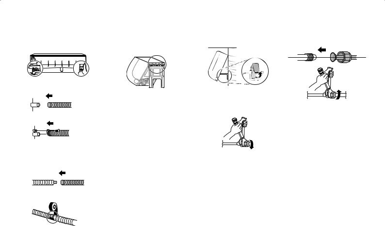
Connecting the Drain
Hose
1Remove the drain cap where you are going to connect the drain hose.
•If you do not use the other drain hose hole, block it with a drain cap.
2Insert the drain hose.
Type 1
Type 2
Installing the Indoor Unit on the Installation Plate
Put the indoor unit onto the installation plate fixed on the wall.
•Check if the hook on top of the rear part of the indoor unit is securely fastened onto the installation plate.
Extending the Drain Hose
1Insert the extending hose into the drain hose joint.
2Wrap the joint area with vinyl tape at least 10 times.
NOTE
•The indoor extended drain hose should be wrapped in insulation to decrease the amount of leakage. You can purchase insulation material separately.
Connecting the Indoor
Unit Pipe
1By reclining the tubing holder, make a space between the bottom of the indoor unit and the wall.
2Remove each of the flare nuts attached to the pipes of the indoor unit.
•First, secure the pipe with an adjustable wrench and then, loosen the flare nut using a torque wrench.
3Tighten the flare nut after inserting the pipe engaged with the flare nut through the center of the indoor unit's pipe.
•After fixing the pipe with the help an adjustable wrench, securely tighten the flare nut using a torque wrench.
Pipe Size |
Torque |
||
mm |
inch |
kgf•cm |
N•m |
Ø 6.35 |
Ø 1/4 |
180~250 |
17.6~24.5 |
|
|
|
|
Ø 9.52 |
Ø 3/8 |
340~420 |
33.3~41.2 |
|
|
|
|
Ø 12.70 |
Ø 1/2 |
550~660 |
53.9~64.7 |
|
|
|
|
Ø 15.88 |
Ø 5/8 |
630~820 |
61.7~80.4 |
|
|
|
|
NOTE
•To prevent gas leakage, apply refrigeration oil on both inner and outer surfaces of the flare.
10 EN
INSTALLING THE OUTDOOR UNIT
Fixing the Outdoor Unit
Fix the outdoor unit firmly to prevent it from falling and dropping.
<![if ! IE]><![endif]>b
a
•• Refer to the measurements for “a” and “b”, depending on the type of chassis. (Chassis type is marked inside the top of the outdoor unit packing box.)
Name of |
a (mm) |
b (mm) |
|
Chassis |
|||
|
|
||
UA3 |
463 |
256 |
|
UL |
519 |
267 |
|
UL2 |
558 |
329 |
|
UE |
546 |
340 |
|
UE1 |
546 |
340 |
|
U24A |
586 |
366 |
|
U4 |
620 |
360 |
NOTE
•• If you install the outdoor unit on a wall, roof, or rooftop, make sure it's mounted on a suitable frame.
•• If the outdoor unit vibrates excessively, secure it using anti-vibration rubber between the unit's feet and the mounting frame.
Connecting the Outdoor
Unit Pipe
1Open the tubing cover.
Type 1
Type 2
2Remove each of the flare nuts attached to the valves of the outdoor unit.
3Tighten the flare nut after inserting the pipe engaged with the flare nut through the center of the outdoor unit's valve.
•• After fixing the valve with the help an adjustable wrench, securely tighten the flare nut using a torque wrench.
Connecting the Drain Plug
If you need to install a drain hose onto an outdoor unit, connect the drain hose after inserting the drain plug with drain washer through the drain hole on the bottom of the outdoor unit.
Pipe Size |
Torque |
||
mm |
inch |
kgf•cm |
N•m |
Ø 6.35 |
Ø 1/4 |
180~250 |
17.6~24.5 |
|
|
|
|
Ø 9.52 |
Ø 3/8 |
340~420 |
33.3~41.2 |
|
|
|
|
Ø 12.70 |
Ø 1/2 |
550~660 |
53.9~64.7 |
Ø 15.88 |
Ø 5/8 |
630~820 |
61.7~80.4 |
NOTE
•• To prevent gas leakage, apply refrigeration oil on both inner and outer surfaces of the flare.
Accessories
Drain Plug |
Drain Cap Drain Washer |
NOTE
•• If the hole is not in use, block it with the drain cap.
•• The quantity and position of the drain cap could be different depending on models.
•• In cold areas, do not use the drain hose on the outdoor unit because the water drained out from the drain hose can freeze, which may cause malfunctioning by damaging the heat exchanger.
EN 11
 Loading...