


 Loading...
LG 55LW4500, 47LW4500, 42LV3550, 42LW4500, 32LW450A User guide
...OWNER’S MANUAL
LCD TV / LED LCD TV / PLASMA TV
Please read this manual carefully before operating the set and retain it for future reference.
www.lg.com

<![endif]>ENGLISH
2LICENSES
LICENSES
Supported licenses may differ by model. For more information about licenses, visit www.lg.com.
Manufactured under license from Dolby Laboratories. “Dolby” and the double-D symbol are trademarks of Dolby Laboratories.
HDMI, the HDMI logo and High-Definition Multimedia Interface are trademarks or registered trademarks of HDMI Licensing LLC.
ABOUT DIVX VIDEO: DivX® is a digital video format created by DivX, LLC, a subsidiary of Rovi Corporation. This is an official DivX Certified® device that plays DivX video. Visit divx.com for more information and software tools to convert your files into DivX video.
ABOUT DIVX VIDEO-ON-DEMAND: This DivX Certified® device must be registered in order to play purchased DivX Video-on-Demand (VOD) movies. To obtain your registration code, locate the DivX VOD section in your device setup menu. Go to vod.divx.com for more information on how to complete your registration.
“DivX Certified® to play DivX® video up to HD 1080p, including premium content.”
“DivX®, DivX Certified® and associated logos are trademarks of Rovi Corporation or its subsidiaries and are used under license.”
“Covered by one or more of the following U.S. patents : 7,295,673; 7,460,668; 7,515,710; 7,519,274”

LICENSES 3
<![if ! IE]><![endif]>ENGLISH

<![endif]>ENGLISH
4TABLE OF CONTENTS
TABLE OF CONTENTS
2LICENSES
6ASSEMBLING AND PREPARING
6Unpacking
9Separate purchase
9Parts and buttons
16 Lifting and moving the TV
16 Setting up the TV
16 - Attaching the stand
20- Not using the Desk Type stand
21- Mounting on a table
22- Mounting on a wall
24- Tidying cables
25- Positioning your display
25- Connection of TV
40- Switch on/off EPG
40- Select a programme
41- NOW/NEXT Guide Mode
41- 8 Day Guide Mode
41- Date Change Mode
41- Extended Description Box
41- Record/Remind Setting Mode
41- Remind Setting Mode
42- Schedule List Mode
42 Using additional options
42 - Adjusting aspect ratio
44- Changing AV modes
44- Using the input list
45- Locking the buttons on the TV (Child Lock)
46Using the quick menu
47Using the Customer Support
47- Testing Software Update
48- Testing the Picture / Sound
48- Using Signal Test
48- Using the product or service information
26 REMOTE CONTROL |
|
49 3D IMAGING |
|||
|
|
|
|||
30 |
WATCHING TV |
49 |
3D Technology |
||
50 |
- When Using 3D glasses |
||||
30 |
Connecting an antenna |
||||
50 |
- 3D Imaging Viewing Range |
||||
30 |
Turning the TV on for the first time |
51 |
Watching 3D images |
||
31 |
Watching TV |
|
|
|
|
31 |
Managing programmes |
|
53 ENTERTAINMENT |
||
31 |
- Automatically setting up programme |
|
|||
53 |
- Connecting to a wired network |
||||
33 |
- Cable DTV Setting (In Cable mode |
||||
|
only) |
54 |
- Network Status |
||
34 |
- Manually setting up programme (In |
55 |
- Connecting USB storage devices |
||
|
digital mode) |
56 |
- Browsing files |
||
35 |
- Manually setting up programme (In |
57 |
- Viewing movies |
||
|
analogue mode) |
60 |
- Viewing photos |
||
36 |
- Booster |
62 |
- Listening to music |
||
36 |
- Editing your programme list |
64 |
- DivX® VOD Guide |
||
38- CI [Common interface] Information
39- Selecting the programme list
40EPG (Electronic Programme Guide) (In digital mode)

|
|
|
|
TABLE OF CONTENTS 5 |
||
65 |
CUSTOMIZING TV SETTINGS |
91 |
Fastext |
|
||
91 |
- Page selection |
|||||
65 |
Accessing main menus |
|||||
91 |
Special Teletext Function |
|||||
66 |
Customizing settings |
|||||
|
|
|
|
|||
66 |
- SETUP settings |
92 DIGITAL TELETEXT |
||||
67 |
- PICTURE settings |
|||||
|
|
|
|
|||
92 |
Teletext within digital service |
|||||
73 |
- AUDIO settings |
|||||
76 |
- TIME settings |
92 |
Teletext in digital service |
|||
77 |
- LOCK settings |
93 MAINTENANCE |
||||
78 |
- OPTION settings |
|||||
81 |
- NETWORK Settings |
|||||
|
|
|
|
|||
93 |
Cleaning your TV |
|||||
|
|
|||||
82 |
MAKING CONNECTIONS |
93 - Screen and frame |
||||
93 |
- Cabinet and stand |
|||||
|
|
|||||
83 |
Connection overview |
93 |
- Power cord |
|||
84 |
Connecting to a HD receiver, DVD, or |
94 |
Preventing “Image burn” or “Burn-in” on |
|||
|
VCR player |
|
|
your TV screen |
||
84 |
- HDMI connection |
95 TROUBLESHOOTING |
||||
84 |
- DVI to HDMI connection |
|||||
84 |
- Component connection |
|||||
|
|
|
|
|||
85 |
- Euro Scart connection |
97 SPECIFICATIONS |
||||
86 |
- Composite connection |
|||||
86 |
Connecting to a PC |
|
|
|
|
|
86 |
- HDMI connection |
109 IR CODES |
||||
86 |
- DVI to HDMI connection |
|||||
86 |
- RGB Connection |
|
|
|
|
|
87 |
Connecting to an audio system |
110 EXTERNAL CONTROL DE- |
||||
87 |
- Digital optical audio connection |
|||||
|
|
VICE SETUP |
||||
88 |
- Headphone connection |
|
|
|||
110 |
RS-232C Setup |
|||||
88 |
Connecting to a USB |
|||||
88 |
Connecting to a CI Module |
110 |
Type of connector; |
|||
89 |
SIMPLINK connection |
|
|
D-Sub 9-Pin Male |
||
89 |
- Activating the SIMPLINK feature |
110 |
RS-232C Configurations |
|||
|
|
111 |
Communication Parameters |
|||
90 |
TELETEXT |
111 |
Command reference list |
|||
112 Transmission / Receiving Protocol |
||||||
90 |
Switch On/Off |
|||||
|
|
|
|
|||
90 |
Simple Text |
117 |
OPEN SOURCE LICENSE |
|||
90 |
- Page selection |
|||||
|
|
|
|
|||
117 |
Open source software notice |
|||||
90 |
Top Text |
|||||
90 |
- Block / Group / Page Selection |
|
|
|
|
|
90 |
- Direct Page Selection |
|
|
|
|
|
<![endif]>ENGLISH
6ASSEMBLING AND PREPARING
ASSEMBLING AND PREPARING
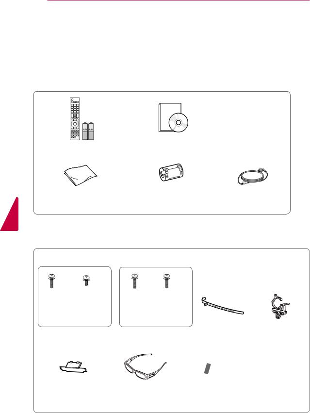
Unpacking
Check your product box for the following items. If there are any missing accessories, contact the local dealer where you purchased your product. The illustrations in this manual may differ from the actual product and item.
Remote control and batteries(AAA) |
Owner’s Manual |
<![endif]>ENGLISH
Polishing cloth1 (This item is not |
Ferrite core |
Power cord (This item is not |
included for all models.) |
(Depending on model) |
included for all models.) |
1Gently wipe the spots on the cabinet with the polishing cloth.
Only 42/50PT25**, 50/60PV25**, 42/50PT35**, 50PV35**, 50/60PZ25**, 42/50PW45**, 50/60PZ55**, 42/50PT45**
x 4 |
x 3 |
x 4 |
x 3 |
|
M4 x 26 |
M5 x 14.5 |
M4 x 28 |
M5 x 24 |
|
(Except for 60PV25**, |
(Only 60PV25**, |
|
||
60PZ25**, 60PZ55**) |
60PZ25**, 60PZ55**) |
|
||
|
Screw for assembly |
Cable holder |
Power cord holder |
|
Protection cover |
3D glasses |
Protection cover |
|
(AG-S250 : Depending |
tape |
|
on model) |
|

ASSEMBLING AND PREPARING 7
Only 22LK33**
Cable holder |
Protection cover |
|
|
Only 19/22/26LV25**, 22/26LV55**, 19/22LV23** |
|
||
x 2 |
x 2 |
x 4 |
|
|
|
or |
|
(M4x6) |
(M4x16) |
M4 x 14 |
|
(Except for 19/22LV23**) |
(Only 19/22LV23**) |
|
|
Screw for assembly |
Cable holder |
DC Adapter |
|
Only 26/32LK33**, 32/37/42LK43**, 32/42/47LK53**, 32/37/42LK45**, 32/42LK55**, 47LK95**, 32/37/42LK46**
x 8
(M4x20) |
(Except for 47LK53**, |
|
|
|
47LK95**) |
|
(Only 47LK95**) |
|
|
|
|
Screw for assembly |
Screw for fixing |
Protection cover |
FPR 3D glasses1 |
Only 32LV25**, 32/37/40/42/47LV35**, 32/42/47/55LW45**, 32/37/42/47LV45**, 32/42LV34**, 42/47LW54**, 32/37/42/47LV36**
x 8 |
x 8 |
|
|
(M4x12) |
(M4x14) |
(Only 32LV25**, |
(Only 32/ |
(Except for 32LV25**) |
(Only 32LV25**) |
32/37LV35**, 32LW45**, |
42/47/55LW45**, |
|
|
32/37LV45**, 32LV34**, |
42/47LW54**) |
Screw for assembly |
32/37LV36**) |
FPR 3D glasses1 |
|
|
|
Screw for fixing |
|
<![endif]>ENGLISH
1The number of 3D glasses may differ depending on the country.
<![endif]>ENGLISH
8ASSEMBLING AND PREPARING
 CAUTION
yyDo not use any pirated items to ensure the safety and product life span.
yyAny damages or injuries by using pirated items are not covered by the warranty.
 NOTE
NOTE
yyThe items supplied with your product may vary depending on the model.
yyProduct specifications or contents of this manual may be changed without prior notice due to upgrade of product functions.
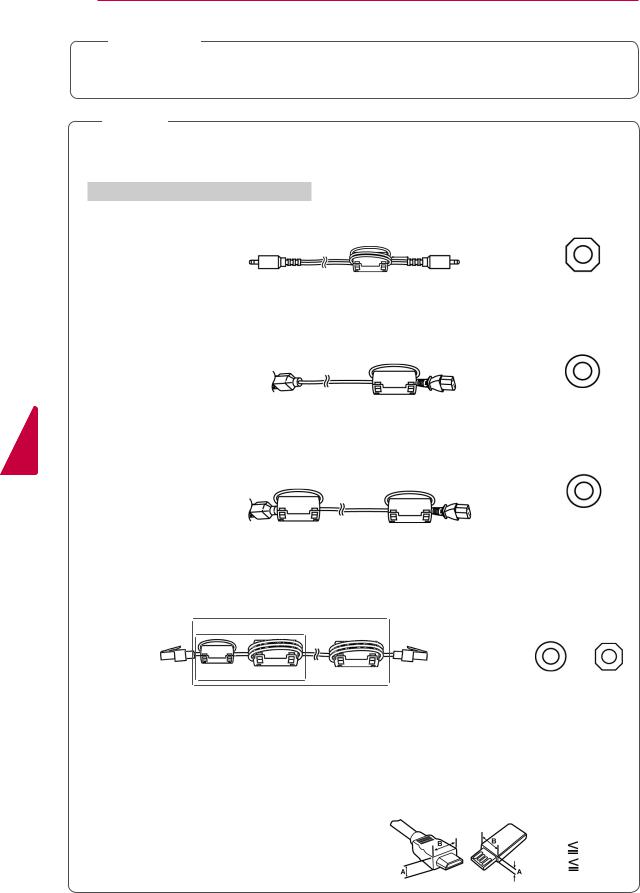
How to use the ferrite core(Only Plasma TV)
1Use the ferrite core to reduce the electromagnetic interference in the PC audio cable.
Wind the PC audio cable on the ferrite core three times. Place the ferrite core close to the TV.
[to an External device] |
10 mm(+ / - 5 mm) |
[to the TV] |
|
[Figure 1] |
(Gray) |
[Cross Section of |
|
|
Ferrite Core] |
2Use the ferrite core to reduce the electromagnetic interference in the power cable. Wind the power cable on the ferrite core once. Place the ferrite core close to the TV.
[to a wall plug] |
[to the TV] |
|
(Black) |
[Figure 2] |
[Cross Section of |
|
Ferrite Core] |
3Use the ferrite core to reduce the electromagnetic interference in the power cable.
Wind the power cable on the ferrite core once. Place the ferrite core close to the TV and a wall plug.
[to a wall plug] |
[to the TV] |
(Black) |
|
|
[Figure 3] |
[Cross Section of |
|
Ferrite Core] |
||
|
4Use the ferrite core to reduce the electromagnetic interference in the LAN cable. Wind the LAN cable once on the small ferrite core and three times on the big ferrite core. Place the
ferrite core close to the TV.
|
|
(2) |
|
|
|
|
|
(1) |
|
|
|
A (Gray) |
B (Gray) |
[to the TV] |
|
|
|
[to an External |
|
|
|
|
|
device] |
|
|
|
A |
B |
|
B |
|
|
|
|
|
|
|
|||
[Figure 4] |
|
[Cross Section of |
||||
|
|
|
|
|||
|
|
|
|
Ferrite Core] |
||
|
|
|
|
|
||
-If there is one ferrite core, follow as shown in Figure 1.
-If there are two ferrite cores, follow as shown in Figures 1 and 2.
-If there are three ferrite cores, follow as shown in Figures 1 and 3.
-If there are four ferrite cores, follow as shown in Figures 1, 2 and 4(1).
-If there are five ferrite cores, follow as shown in Figures 1, 3 and 4(1).
-If there are six ferrite cores, follow as shown in Figures 1, 3 and 4(2).
yyFor an optimal connection, HDMI cables and USB de- |
|
|
vices should have bezels less than 10 mm thick and |
|
|
18 mm width.(Except for 42/50PT25**, 50/60PV25**, |
|
|
42/50PT35**, 50PV35**, 50/60PZ25**, 42/50PW45**, |
*A |
10 mm |
50/60PZ55**, 22/26/32LK33**, 32/37/42LK43**, |
*B |
18 mm |
32/42/47LK53**, 47LK95**, 42/50PT45**) |
|
|
ASSEMBLING AND PREPARING 9
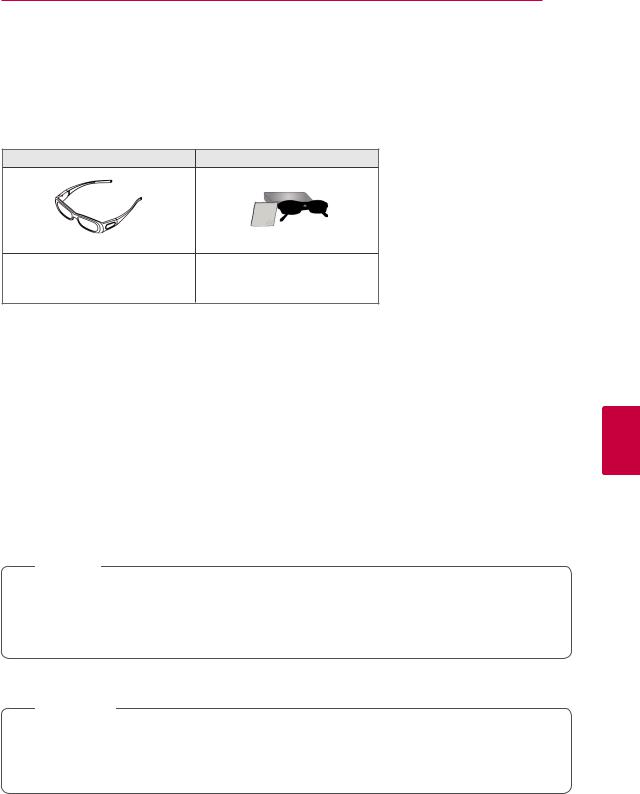
Separate purchase
Separate purchase items can be changed or modified for quality improvement without any notification. Contact your dealer for buying these items.
This device only works with compatible LG Plasma TV, LED LCD TV or LCD TV.
Only Plasma TV |
Only LCD / LED LCD TV |
3D glasses |
FPR 3D glasses1 |
|
(AG-S230, AG-S250, AG-S270 : |
(AG-F2** : Only 3D Models) |
|
Only 3D Models) |
||
|
1The model name or design of 3D glasses may be changed without prior notice due to upgrade of product functions.
<![if ! IE]><![endif]>ENGLISH
Parts and buttons
 NOTE
NOTE
yyThe TV can be placed in standby mode in order to reduce the power consumption. And the TV should be turned off if it will not be watched for some time, as this will reduce energy consumption.
yyThe energy consumed during use can be significantly reduced if the level of brightness of the picture is reduced, and this will reduce the overall running cost.
 CAUTION
yyDo not step on the glass stand or subject it to any impact. It may break, causing possible injury from fragments of glass, or the TV may fall.
yyDo not drag the TV. The floor or the product may be damaged.
yySome models have a thin film attached on to the screen and this must not be removed.
<![endif]>ENGLISH
10 ASSEMBLING AND PREPARING
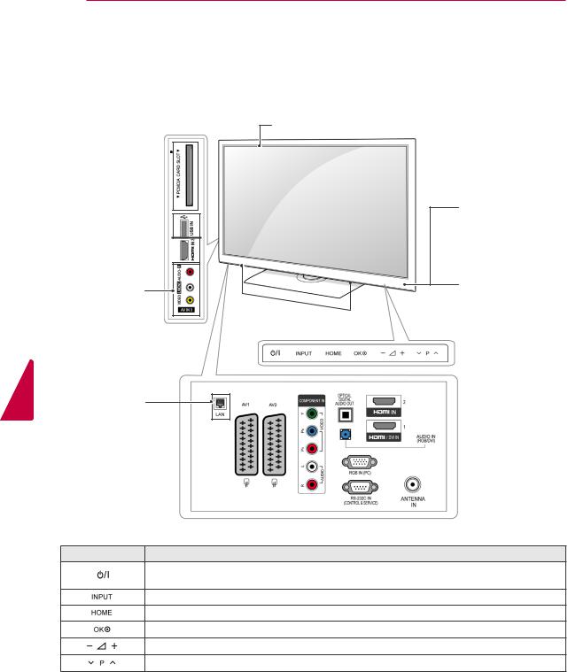
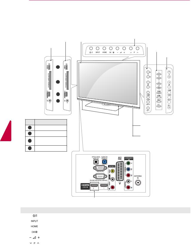
yyImage shown may differ from your TV.
Only 50/60PZ25**, 42/50PW45**, 50/60PZ55**, 42/50PT45**
Screen
PCMCIA Card 
Slot
USB input
HDMI IN
AV (Audio and |
|
Video) IN |
Speakers |
(Only 50/60PZ250T,
42/50PW450T,
42/50PW451T,
50/60PZ550T)
Remote control and intelligent1 sensors
Power Indicator
Red – In Standby mode
Off – TV turns on
 Touch buttons2
 Connection panel (See p.82)
Button |
Description |
Turns the power on or off
Changes the input source
Accesses the main menus, or saves your input and exits the menus
Selects the highlighted menu option or confirms an input
Adjusts the volume level
Scrolls through the saved programmes
1 Intelligent sensor - Adjusts the image quality corresponding to the surrounding environment.
2Touch Button - You can use the desired button function by touching.
ASSEMBLING AND PREPARING 11
yyImage shown may differ from your TV.
Only 50/60PV25**, 42/50PT35**, 50PV35**, 42/50PT25**
Screen
PCMCIA Card 
Slot
|
|
|
|
|
|
|
|
|
|
|
|
|
Remote control and |
|
USB input |
|
|
|
|
|
|
|
|
|
|
intelligent1 sensors |
|||
|
|
|
|
|
|
|||||||||
|
|
|
|
|
|
|
|
|
|
|
|
|||
HDMI IN |
|
|
|
|
|
|
|
|
|
|
|
Power Indicator |
||
|
|
|
|
|
|
|
|
|
|
|
||||
|
|
|
|
|
|
|
|
|
|
|
||||
|
|
|
|
|
|
|
|
|
|
|
|
|
||
|
|
|
|
|
|
|
|
|
|
|
|
|
Red – In Standby |
|
|
|
|
|
|
|
|
|
|
||||||
AV (Audio and |
|
|
|
|
|
|
|
|
|
|
|
mode |
||
|
|
|
|
|
|
|
|
|
|
|
Off – TV turns on |
|||
|
|
|
||||||||||||
|
|
|
|
|
|
|
||||||||
Video) IN |
|
|
|
|
Speakers |
|
|
|
|
|
|
|||
(Only |
|
|
|
|
|
|
|
|
|
|
|
|
|
Touch buttons2 |
|
|
|
|
|
|
|
|
|
|
|
|
|
||
|
|
|
|
|
|
|
|
|
|
|
|
|
||
|
|
|
|
|
|
|
|
|
|
|
|
|||
|
|
|
|
|
|
|
|
|
|
|
||||
50PV350T) |
|
|
|
|
|
|
|
|
|
|
|
|||
 Connection panel (See p.82)
Button |
Description |
Turns the power on or off
Changes the input source
Accesses the main menus, or saves your input and exits the menus
Selects the highlighted menu option or confirms an input
Adjusts the volume level
Scrolls through the saved programmes
1 Intelligent sensor - Adjusts the image quality corresponding to the surrounding environment.
2Touch Button - You can use the desired button function by touching.
<![endif]>ENGLISH
12 ASSEMBLING AND PREPARING
<![endif]>ENGLISH
yyImage shown may differ from your TV.
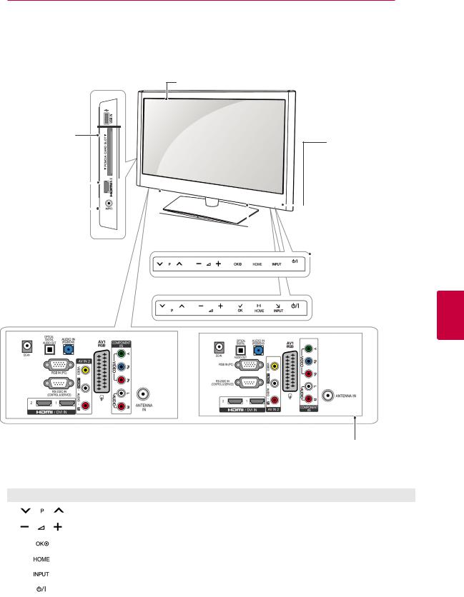
Only 22/26/32LK33**, 32/37/42LK43**, 32/42/47LK53**(Except for 32/42/47LK530T), 47LK95**
Screen
(Only 22/26/32LK33**)
(Only 32/37/42LK43**, 32/42/47LK53**, 47LK95**)
 1
1 
 2
2 
 3
3 
 4
4 
Speakers
No. Description
1USB input
2PCMCIA Card Slot
3HDMI IN(Except for 22LK33**)
4Headphone Socket
(Only 22LK33**)
(Only 26/32LK33**)
(Only 32/37/42LK43**)
(Only 32/42/47LK53**, 47LK95**)
Remote control and intelligent1 sensors
Power Indicator
(Can be adjusted using the Power Indicator in the OPTION menu.)
 Connection panel (See p.82)
(Except for 22/26/32LK33**)
Button |
Description |
|
Turns the power on or off |
|
|
|
Changes the input source |
|
|
|
Accesses the main menus, or saves your input and exits the menus |
|
Selects the highlighted menu option or confirms an input |
|
|
|
Adjusts the volume level |
|
|
|
Scrolls through the saved programmes |
|
|
1Intelligent sensor - Adjusts the image quality corresponding to the surrounding environment.(Only 32/42/47LK53**, 47LK95**)
ASSEMBLING AND PREPARING 13
yyImage shown may differ from your TV.
Only 19/22/26LV25**, 19/22LV23**, 22/26LV55**
Screen
USB input

PCMCIA Card
Slot Remote control and intelligent1 sensors
HDMI IN |
|
|
|
|
|
|
|
|
||||
|
|
|
|
|
|
|
|
|||||
(Only 26LV25**, |
|
|
|
|
|
|
|
|
|
Power Indicator |
||
|
|
|
|
|
|
|
|
|||||
26LV55**) |
|
|
|
|
|
|
(Can be adjusted using |
|||||
|
|
|
|
|
||||||||
|
|
|
|
|
||||||||
Headphone |
|
|
|
|
|
|
|
|
the Power Indicator in |
|||
Socket |
|
Speakers |
|
|
|
the OPTION menu.) |
||||||
|
|
|
|
|
|
(Only19/22/26LV25**) |
|
|
Touch buttons2 |
|||
|
|
|
|
|
|
(Only22/26LV55**,19/22LV23**) |
|
|
||||
|
|
|
|
|
|
|
|
|||||
|
|
|
|
|
|
|
|
|
||||
<![endif]>ENGLISH
(Only19/22/26LV25**,19/22LV23**) |
(Only22/26LV55**) |
Connection panel (See p.82)
Button |
Description |
|
Scrolls through the saved programmes |
|
|
|
Adjusts the volume level |
|
|
|
Selects the highlighted menu option or confirms an input |
|
|
|
Accesses the main menus, or saves your input and exits the menus |
|
|
|
Changes the input source |
|
|
|
Turns the power on or off |
|
|
1 Intelligent sensor - Adjusts the image quality corresponding to the surrounding environment. 2. Touch Button - You can use the desired button function by touching.
<![endif]>ENGLISH
14 ASSEMBLING AND PREPARING
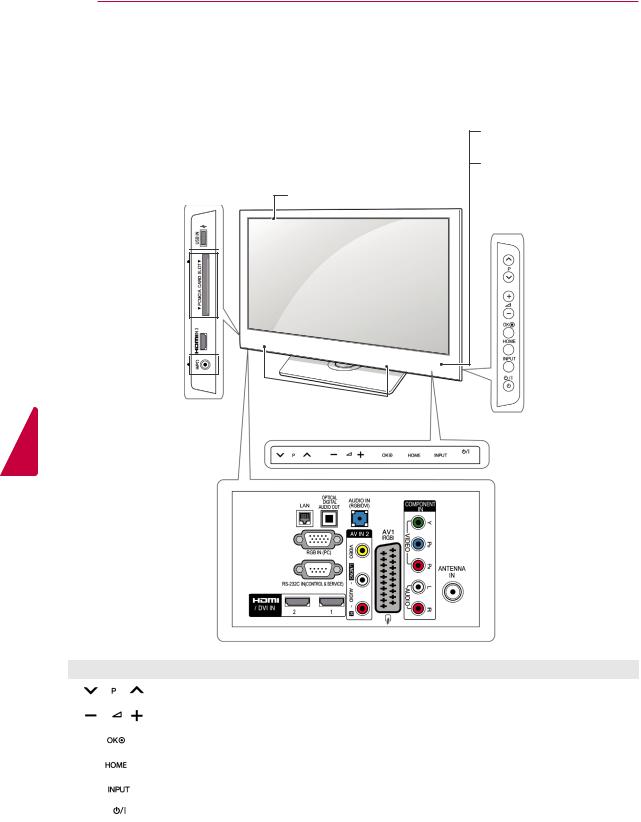
yyImage shown may differ from your TV.
Only 32/42/47LK530T, 32/42LK550T, 32/37/42/47LV355T
Screen
USB input


PCMCIA Card 
Slot
HDMI IN 


Headphone 

Socket
Speakers
Remote control and intelligent1 sensors
Power Indicator
(Can be adjusted using the Power Indicator in the OPTION menu.)
 (Only 32/42/47LK530T)
 Touch buttons2
(Except for 32/42/47LK530T)
 Connection panel (See p.82)
Button |
Description |
|
Scrolls through the saved programmes |
|
|
|
Adjusts the volume level |
|
|
|
Selects the highlighted menu option or confirms an input |
|
|
|
Accesses the main menus, or saves your input and exits the menus |
|
|
|
Changes the input source |
|
|
|
Turns the power on or off |
|
|
1 Intelligent sensor - Adjusts the image quality corresponding to the surrounding environment. 2. Touch Button - You can use the desired button function by touching.
ASSEMBLING AND PREPARING 15
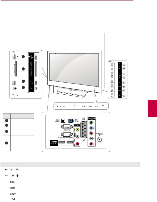
yyImage shown may differ from your TV.
Only 32/37/42LK45**, 32/42LK55**, 32LV25**, 32/42LV34**, 32/37/40/42/47LV35**, 32/37/42/47LV45**, 32/42/47/55LW45**, 42/47LW54**, 32/37/42LK46**, 32/37/42/47LV36**(Except for 32/42LK550T,
32/37/42/47LV355T)
(Only 32/37/42LK45**, |
|
|
||||
32/42LK55**, 32/37/42LK46**) |
|
Screen |
||||
|
||||||
|
|
1 |
|
|
|
|
|
|
|
|
|
|
|
|
|
|
|
|
||
 2
2 
 3
3 
 4
4 
Speakers
(Except for 32/37/ 42LK45**, 32/42LK55**, 32/37/42LK46**)
No. Description
1USB input
2PCMCIA Card Slot
3HDMI IN(Except for 32/42LV34**)
Headphone
4Socket(Except for 32/42LV34**)
Remote control and intelligent1 sensors
Power Indicator
(Can be adjusted using the Power Indicator in the OPTION menu.)
 (Only 32/42LV34**)
 (Only
(Only
42/47LW54**)
 Touch buttons2 (Except for 32/42LV34**, 42/47LW54**)
 Connection panel (See p.82)
<![endif]>ENGLISH
Button |
Description |
|
Scrolls through the saved programmes |
|
|
|
Adjusts the volume level |
|
|
|
Selects the highlighted menu option or confirms an input |
|
|
|
Accesses the main menus, or saves your input and exits the menus |
|
|
|
Changes the input source |
|
|
|
Turns the power on or off |
|
|
1 Intelligent sensor - Adjusts the image quality corresponding to the surrounding environment. 2. Touch Button - You can use the desired button function by touching.
<![endif]>ENGLISH
16 ASSEMBLING AND PREPARING
Lifting and moving the TV
When moving or lifting the TV, read the following advice to prevent the TV from being scratched or damaged and for safe transportation regardless of its type and size.
 CAUTION
yyAvoid touching the screen at all times, as this may result in damage on the screen or some of the pixels used to create images.
yyIt is recommended to move the TV in the box or packing material that the TV originally came in.
yyBefore moving or lifting the TV, disconnect the Power cord and all cables.
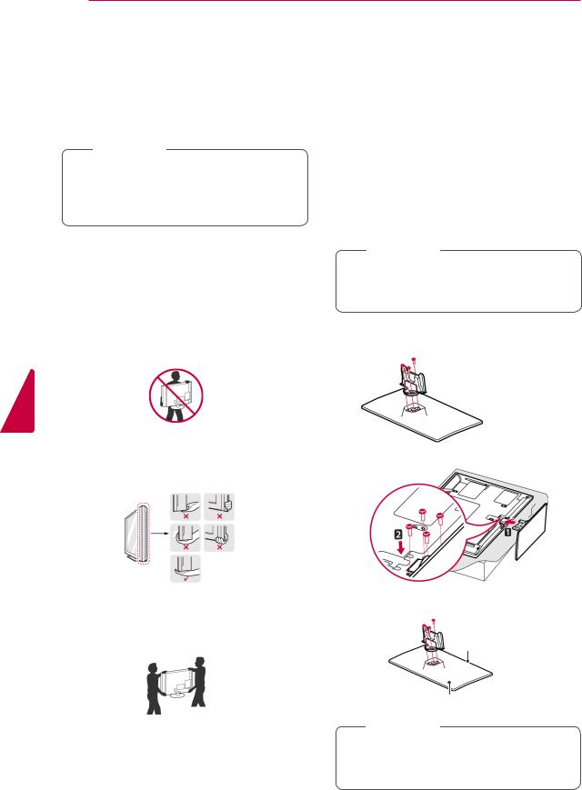
yyWhen holding the TV, the screen should face away from you to prevent the screen from scratches.
yyHold the top and bottom of the TV frame firmly. Make sure not to hold the transparent part, speaker, or speaker grill area.
yyWhen transporting a large TV, there should be at least 2 people.
yyWhen transporting the TV by hand, hold the TV as shown in the following illustration.
yyWhen transporting the TV, do not expose the TV to jolts or excessive vibration.
yyWhen transporting the TV, keep the TV upright, never turn the TV on its side or tilt towards the left or right.
Setting up the TV
yyImage shown may differ from your TV.
Put your TV on a pedestal stand and mount the TV on a table or wall.
Attaching the stand
(Only 42/50PT25**, 50/60PV25**, 42/50PT35**, 50PV35**, 50/60PZ25**, 42/50PW45**, 50/60PZ55**, 42/50PT45**)
1Lay the TV with the screen side down on a flat surface.
 CAUTION
yyLay a foam mat or soft protective cloth on the surface to protect the screen from damage.
2Assemble the parts of the Stand Body with the
Stand Base of the TV.
 Stand Body
 Stand Base
3Secure the TV and the stand with the 4 screws.
Make sure to assemble the front and rear side of the stand.
Front
Rear
 CAUTION
yyTighten the screws firmly to prevent the TV from tilting forward. Do not over tighten.
|
ASSEMBLING AND PREPARING 17 |
||
(Only 22LK33**) |
(Only 26/32LK33**, 32/37/42LK43**, |
|
|
1 Lay the TV with the screen side down on a flat |
32/42/47LK53**, 32/37/42LK45**, 32/42LK55**, |
||
47LK95**, 32/37/42LK46**) |
|||
surface. |
|||
|
|
||
 CAUTION
yyLay a foam mat or soft protective cloth on the surface to protect the screen from damage.
2 Assemble the TV as shown.
(Only 19/22LV23**)
1Lay the TV with the screen side down on a flat surface.
 CAUTION
1Lay the TV with the screen side down on a flat surface.
 CAUTION
yyLay a foam mat or soft protective cloth on the surface to protect the screen from damage.
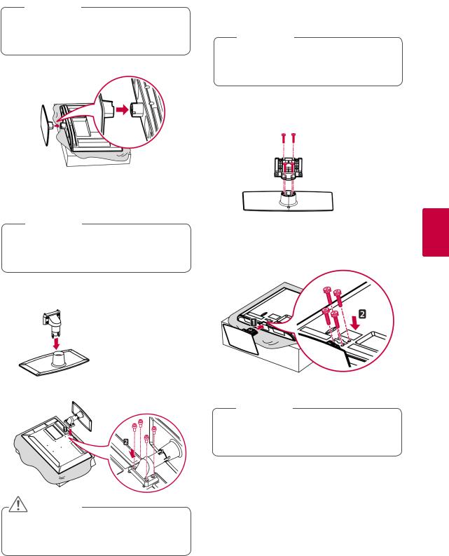
2Assemble the parts of the Stand Body with the
Stand Base of the TV.
 Stand Body
 Stand Base
yyLay a foam mat or soft protective cloth on the surface to protect the screen from damage.
2Assemble the parts of the Stand Body with the
Stand Base of the TV.
 Stand Body
 Stand Base
3 Secure the TV and the stand with the 4 screws.
3 Secure the TV and the stand with the 4 screws.
 CAUTION
yyTighten the screws firmly to prevent the TV from tilting forward. Do not over tighten.
 CAUTION
<![endif]>ENGLISH
yyTighten the screws firmly to prevent the TV from tilting forward. Do not over tighten.

<![endif]>ENGLISH
18 ASSEMBLING AND PREPARING
(Only 19/22/26LV25**, 22/26LV55**)
1Lay the TV with the screen side down on a flat surface.
 CAUTION
yyLay a foam mat or soft protective cloth on the surface to protect the screen from damage.
2Assemble the parts of the Stand Body with the
Stand Base of the TV.
|
|
Stand |
|
||
(M4x6) |
|
Body |
|
||
|
Stand Base |
|
3 Secure the TV and the stand with the 2 screws.
(M4x16)
 CAUTION
yyTighten the screws firmly to prevent the TV from tilting forward. Do not over tighten.
(Only 32LV25**, 32/42LV34**, 32/37/40/42/47LV35**, 32/37/42/47LV45**, 32/42/47/55LW45**, 32/37/42/47LV36**)
1Lay the TV with the screen side down on a flat surface.
 CAUTION
yyLay a foam mat or soft protective cloth on the surface to protect the screen from damage.
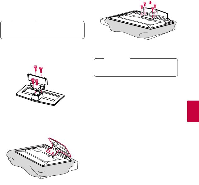
2Assemble the parts of the Stand Body with the
Stand Base of the TV.
Stand Body
Only 32LV25**
 Stand Base
 Stand Body
Except for 32LV25**
 Stand Base
3 Secure the TV and the stand with the 4 screws.
 CAUTION
yyTighten the screws firmly to prevent the TV from tilting forward. Do not over tighten.
|
ASSEMBLING AND PREPARING 19 |
|
|
|
|
(Only 42/47LW54**) |
4 Secure the TV and the stand with the 4 screws. |
|
1Lay the TV with the screen side down on a flat surface.
 CAUTION
yyLay a foam mat or soft protective cloth on the surface to protect the screen from damage.
2Assemble the parts of the Stand Body with the
Stand Base of the TV.
 CAUTION
yyTighten the screws firmly to prevent the TV from tilting forward. Do not over tighten.
 Stand Body
 Stand Base
3 Assemble the TV as shown.
<![endif]>ENGLISH
<![endif]>ENGLISH
20 ASSEMBLING AND PREPARING
Not using the Desk Type stand
yyImage shown may differ from your TV.
(Only 42/50PT25**, 50/60PV25**, 42/50PT35**, 50PV35**, 50/60PZ25**, 42/50PW45**, 50/60PZ55**, 42/50PT45**)
yyPush the supplied Protection cover into the
opening at the bottom of the TV until it locks in place.
yyAttach the Protection cover tape.
-This will protect the opening from accumulating dust and dirt.
-When installing the wall mounting bracket, use the Protection cover.
Protection |
cover tape |
Protection cover
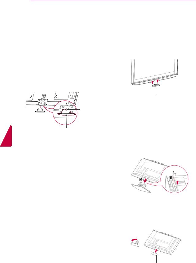
(Only 26/32LK33**, 32/37/42LK43**, 32/42/47LK53**, 32/37/42LK45**, 32/42LK55**, 47LK95**, 32/37/42LK46**)
1Push the supplied Protection cover into the opening at the bottom of the TV until clicking sound.
Protection cover
(Only 22LK33**)
1Lay the TV with the screen side down on a flat surface.
2Remove the 2 screws and pull the stand away from the TV.
3Push the supplied protection cover into the opening at the bottom of the TV until it locks in place.
This will protect the opening from accumulating dust and dirt.
Protection cover
|
|
|
ASSEMBLING AND PREPARING 21 |
|||
Mounting on a table |
|
|
|
|||
|
|
Securing the TV to a table |
|
|||
yyImage shown may differ from your TV. |
yyImage shown may differ from your TV. |
|||||
(Only 26/32LK33**, 32/37/42LK43**, |
||||||
1 Lift and tilt the TV into its upright position on a |
||||||
32/37/42LK45**, 32/42LK53**, 32/42LK55**, |
||||||
table. |
|
32LV25**, 32/37LV35**, 32LW45**, 32/37LV45**, |
||||
- Leave a 10 cm (minimum) space from the |
32LV34**, 32/37/42LK46**, 32/37LV36**) |
|||||
wall for proper ventilation. |
|
Fix the TV to a table to prevent from tilting forward, |
||||
|
|
damage, and potential injury. |
||||
|
|
Mount the TV on a table, and then insert and |
||||
|
|
tighten the supplied screw on the rear of the stand. |
||||
10 cm |
|
|
|
|
|
|
|
cm |
|
|
|
|
|
10 cm |
10 |
|
|
|
|
|
|
|
|
|
|
||
|
10 cm |
|
|
|
|
|
2Connect the Power cord to a wall outlet.
 WARNING
yyTo prevent the TV from falling over, the TV should be securely attached to the floor/wall per installation instructions.
Tipping, shaking, or rocking the TV may cause injury.
 CAUTION
yyDo not place the TV near or on sources of heat, as this may result in fire or other damage.
 NOTE
NOTE
yySwivel 20 degrees to the left or right and adjust the angle of the TV to suit your view.(Except for 22LK33**, 19/22/26LV25**, 22/26LV55**, 19/22LV23**)
<![endif]>ENGLISH
<![endif]>ENGLISH
22 ASSEMBLING AND PREPARING
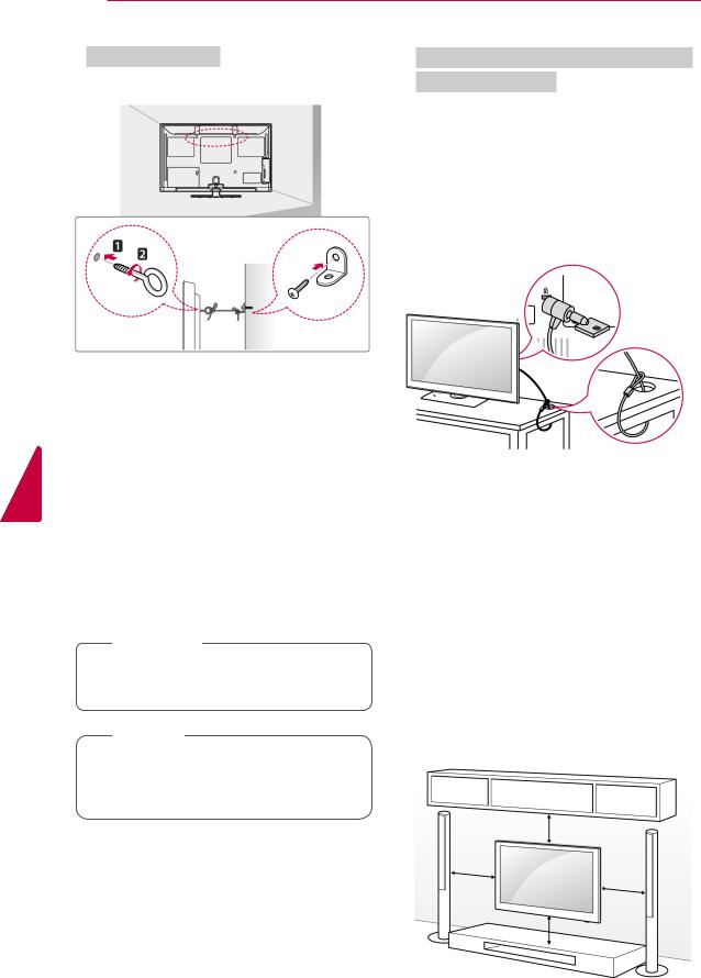
Securing the TV to a wall
yyImage shown may differ from your TV.
1Insert and tighten the eye-bolts, or TV brackets and bolts on the back of the TV.
-If there are bolts inserted at the eye-bolts position, remove the bolts first.
2Mount the wall brackets with the bolts to the wall.
Match the location of the wall bracket and the eye-bolts on the rear of the TV.
3Connect the eye-bolts and wall brackets tightly with a sturdy rope.
Make sure to keep the rope horizontal with the flat surface.
 CAUTION
yyMake sure that children do not climb on or hang on the TV.
 NOTE
NOTE
yyUse a platform or cabinet that is strong and large enough to support the TV securely.
Using the Kensington security system (This feature is not available for all models.)
yyImage shown may differ from your TV. The Kensington security system connector is
located at the rear of the TV. For more information of installation and using, refer to the manual provided with the Kensington security system or visit http://www.kensington.com.
Connect the Kensington security system cable between the TV and a table.
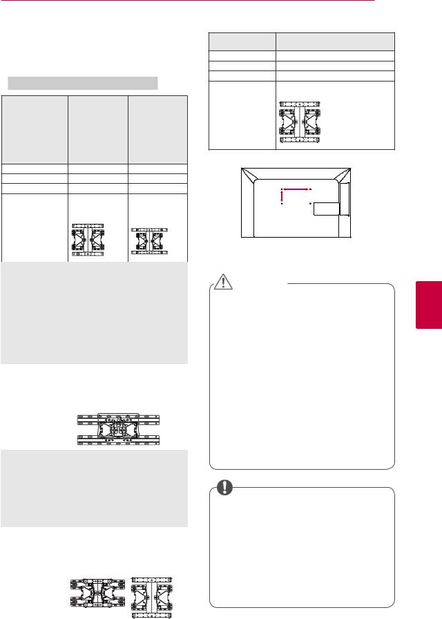
Mounting on a wall
Attach a wall mount bracket at the rear of the TV carefully and install the wall mount bracket on a solid wall perpendicular to the floor. When you attach the TV to other building materials, please contact qualified personnel.
LG recommends that wall mounting be performed by a qualified professional installer.
10 cm
10 cm
10 cm
10 cm
|
|
|
|
ASSEMBLING AND PREPARING 23 |
Make sure to use screws and wall mount |
Model |
42LV34** |
||
bracket that meet the VESA standard. Standard |
VESA (A x B) |
42/47LW54** |
||
dimensions for the wall mount kits are described in |
400 x 400 |
|||
the following table. |
|
|
Standard screw |
M6 |
Separate purchase(Wall Mounting Bracket) |
Number of screws 4 |
|||
Wall mount |
LSW400BX, |
|||
Model |
42/50PT25** |
60PV25** |
bracket |
LSW400BXG |
|
|
|||
|
42/50PT35** |
60PZ25** |
|
|
|
50PV35** |
60PZ55** |
|
|
|
50PZ25** |
|
|
|
|
42/50PW45** |
|
|
|
|
50PZ55** |
|
|
|
|
42/50PT45** |
|
|
|
|
50PV25** |
|
|
|
VESA (A x B) |
400 x 400 |
600 x 400 |
|
|
Standard screw |
M6 |
M8 |
|
A |
Number of screws |
4 |
4 |
|
|
|
B |
|||
Wall mount |
PSW400B, |
PSW600B, |
|
|
bracket |
PSW400BG |
PSW600BG |
|
|
Model |
22LK33** |
26/32LK33** |
|
|
|
|
|
|
|
|
19/22/26LV25** |
32LK43** |
|
|
|
|
|
|
|
|
|
|
|
|
|
|
|||
|
|
|
|
CAUTION |
|
||||
|
22/26LV55** |
32LK45** |
|
|
|
|
|||
|
19/22LV23** |
32LK53** |
|
|
|
|
|
|
|
|
|
yyDisconnect the power first, and then move |
|||||||
|
|
32LK55** |
|
||||||
|
|
|
or install the TV. Otherwise electric shock |
||||||
|
|
32LV25** |
|
||||||
|
|
32LV35** |
|
may occur. |
|||||
|
|
32LV45** |
|
yyIf you install the TV on a ceiling or slanted |
|||||
|
|
32LW45** |
|
||||||
|
|
|
wall, it may fall and result in injury. Use |
||||||
|
|
32LV34** |
|
||||||
|
|
32LK46** |
|
an authorized LG wall mount bracket |
|||||
|
|
32LV36** |
|
and contact the local dealer or qualified |
|||||
VESA (A x B) |
100 x 100 |
200 x 100 |
|
||||||
|
personnel. |
||||||||
Standard screw |
M4 |
M4 |
|
||||||
|
yyDo not over tighten the screws as this may |
||||||||
Number of screws |
4 |
4 |
|
||||||
|
cause damage to the TV and void your |
||||||||
Wall mount |
LSW100B, LSW100BG |
|
|||||||
bracket |
|
|
|
warranty. |
|||||
|
|
|
|
yyUse the screws and wall mount bracket that |
|||||
|
|
|
|
meet the VESA standard. Any damages |
|||||
|
|
|
|
or injuries by misuse or using an improper |
|||||
|
|
|
|
accessory are not covered by the warranty. |
|||||
Model |
37/42LK43** |
40/42/47LV35** |
|||||||
|
|
|
|
|
|
||||
|
37/42LK45** |
42/47LV45** |
|
|
|
|
|
|
|
|
42LK55** |
42/47/55LW45** |
|
|
|
|
|
|
|
|
42/47LK53** |
42/47LV36** |
|
|
|
|
|
|
|
|
|
|
|
|
|
|
|||
|
|
|
|
NOTE |
|
|
|||
|
37LV35** |
|
|
|
|
|
|||
|
37LV45** |
|
|
|
|
|
|
|
|
|
|
|
yyUse the screws that are listed on the |
||||||
|
47LK95** |
|
|
||||||
|
37/42LK46** |
|
|
VESA standard screw specifications. |
|||||
|
37LV36** |
|
|
yyThe wall mount kit includes an installation |
|||||
VESA (A x B) |
200 x 200 |
400 x 400 |
|||||||
|
manual and necessary parts. |
||||||||
Standard screw |
M6 |
M6 |
|
||||||
|
yyThe length of screws may differ |
||||||||
Number of screws |
4 |
4 |
|
||||||
|
depending on the wall mount. Make sure |
||||||||
Wall mount |
LSW200B, |
LSW400B, |
|
||||||
|
to use the proper length. |
||||||||
bracket |
LSW200BG |
LSW400BG |
|
||||||
|
|
|
|
yyFor more information, refer to the manual |
|||||
|
|
|
|
supplied with the wall mount bracket. |
|||||
|
|
|
|
|
|
|
|
|
|
<![endif]>ENGLISH
24 ASSEMBLING AND PREPARING
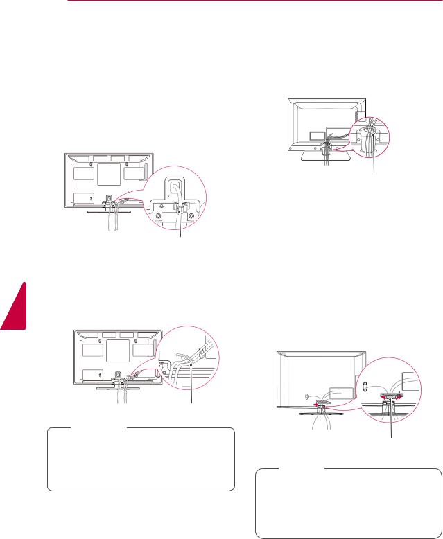
Tidying cables
yyImage shown may differ from your TV.
(Only 42/50PT25**, 50/60PV25**, 42/50PT35**, 50PV35**, 50/60PZ25**, 42/50PW45**, 50/60PZ55**, 42/50PT45**)
1Install the Power cord holder and Power cord. It will help prevent the power cable from being removed by accident.
(Only 22LK33**, 19/22/26LV25**, 22/26LV55**, 19/22LV23**)
1After connecting the cables as necessary, install Cable holder as shown and bundle the cables.
Cable holder
<![endif]>ENGLISH
Power cord holder
2Gather and bind the cables with the Cable
holder.
Install the LAN cable as shown to reduce the electromagnetic wave(Only 50PV350T, 50/60PZ250T, 42/50PW450T, 42/50PW451T, 50/60PZ550T).
Cable holder
 CAUTION
yyDo not move the TV by holding the Cable holder & Power cord holder, as the Cable holders may break, and injuries and damage to the TV may occur.
(Only 26/32LK33**, 32/37/42LK43**, 32/37/42LK45**, 32/42/47LK53**, 32/42LK55**, 47LK95**, 32/37/42LK46**)
1Gather and bind the cables with the Cable management clip.
2 Fix the Cable management clip firmly to the TV.
Cable management clip
 NOTE
NOTE
yyDo not move the TV by holding the Cable management clip, as the Cable management clip may break, and injuries and damage to the TV may occur.
|
ASSEMBLING AND PREPARING 25 |
||
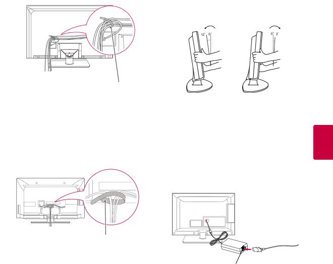
(Only 32LV25**, 32/37/40/42/47LV35**, |
Positioning your display |
|
|
32/42/47/55LW45**, 32/37/42/47LV45**, |
yyImage shown may differ from your TV. |
||
32/42LV34**, 32/37/42/47LV36**) |
|||
|
|
||
1Gather and bind the cables with the Cable holder on the TV back cover.
(Only 22LK33**)
Adjust the position of the panel in various ways for maximum comfort.
• Tilt range
Cable holder
(Only 42/47LW54**)
1Gather and bind the cables with the Cable holder on the TV back cover.
Connection of TV
yyImage shown may differ from your TV.
(Only 19/22/26LV25**, 22/26LV55**, 19/22LV23**)
<![endif]>ENGLISH
Cable holder
DC Adapter
1Connect the antenna cable to the antenna input port on the TV.
2Connect the DC adapter plug to the power input jack on the TV.
3Connect the Power cord to the DC adapter first, then plug the Power cord into the wall power outlet.
<![endif]>ENGLISH
26 REMOTE CONTROL
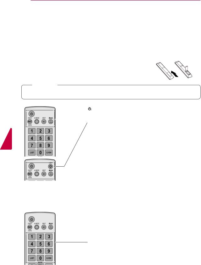
REMOTE CONTROL
The descriptions in this manual are based on the buttons on the remote control. Please read this manual carefully and use the TV correctly.
To replace batteries, open the battery cover, replace batteries (1.5 V AAA) matching  and
and  ends to the label inside the compartment, and close the battery cover. Be sure to point the remote control to the remote control sensor on the TV.
To remove the batteries, perform the installation actions in reverse.
 CAUTION
yyDo not mix old and new batteries, as this may damage the remote control.
(POWER)
Turns the TV on or off.
ENERGY SAVING (See p.67)
 Adjusts the brightness of the screen to reduce energy consumption .
AV MODE (See p.44) Selects an AV mode.
INPUT (See p.44)
Changes the input source; Turns the TV on .
TV/RAD
Selects Radio, TV and DTV programme.
LIGHT
Illuminates the remote control buttons.
Number buttons
Enters numbers.
LIST (See p.39)
Accesses the saved programme list.
Q.VIEW
Returns to the previously viewed programme.
REMOTE CONTROL 27
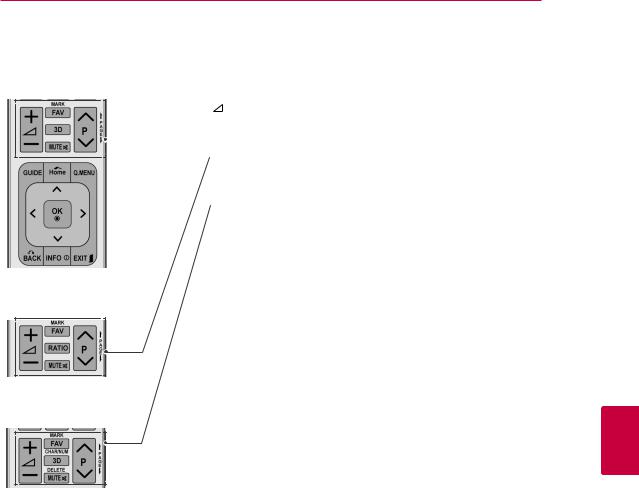
+ -
Adjusts the volume level.
MARK
 Selects a menu or option.
FAV (See p.39)
Accesses your favourite programme list.
3D(Only 3D Models)(See p.49) Used for viewing 3D video.
RATIO (See p.42) Resizes an image.
MUTE
Mutes all sounds.
P
Scrolls through the saved programmes.
PAGE
Moves to the previous or next screen.
CHAR/NUM
Switches between Letter and Number input modes.
DELETE
Deletes letters and numbers.
<![if ! IE]><![endif]>ENGLISH
28 REMOTE CONTROL
<![endif]>ENGLISH
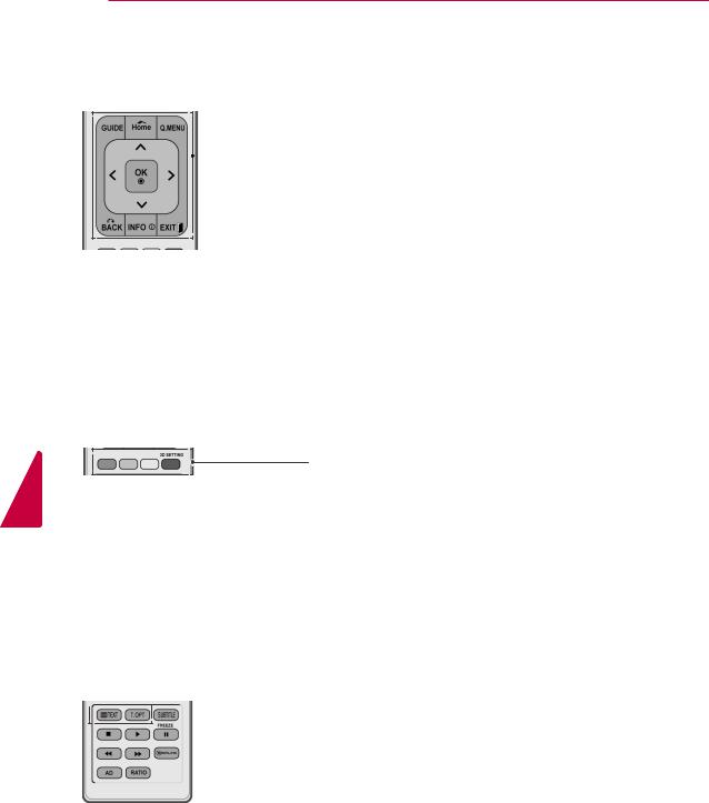
GUIDE
Shows programme guide.
Home
 Accesses the main menus.
Q. MENU (See p.46) Accesses the Quick menus.
Navigation buttons (up/down/left/right) Scrolls through menus or options.
OK
Selects menus or options and confirms your input.
BACK
Returns to the previous level.
INFO (See p.40)
Views the information of the current programme and screen.
EXIT
Clears all on-screen displays and return to TV viewing.
Coloured buttons
These buttons are used for teletext (on TELETEXT models only),
Programme edit.
3D SETTING(Only 3D Models) Use this to view 3D video.


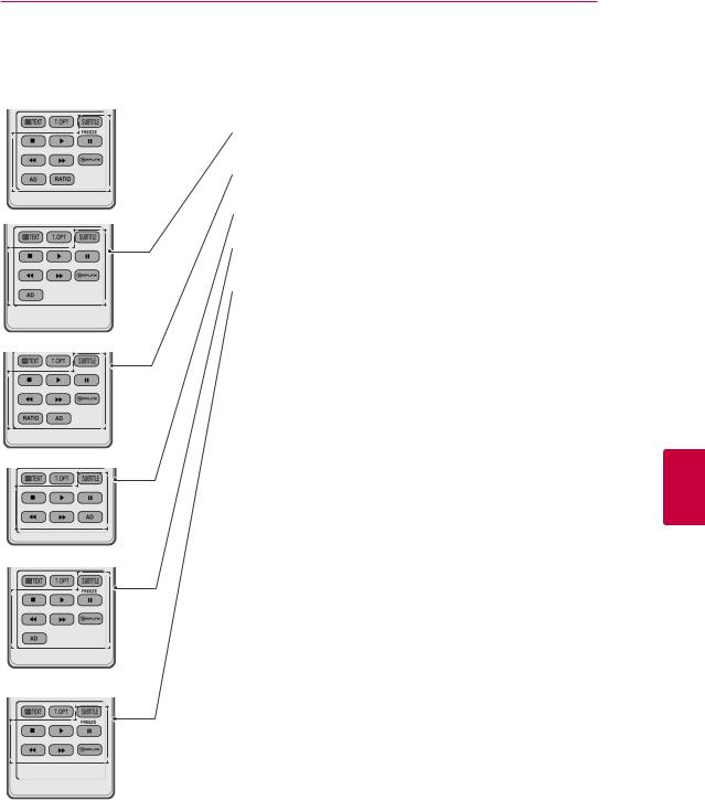
 TELETEXT BUTTONS (See p.90) These buttons are used for teletext.
For further details, see the ‘Teletext’ section.
REMOTE CONTROL 29
SUBTITLE
 Recalls your preferred subtitle in digital mode.
Control buttons(  ,
, ,
, ,
, ,
, )
)
Controls the MY MEDIA menus, or the SIMPLINK compatible devices (USB,SIMPLINK).
FREEZE
Freezes the current frame while using the TV, AV, Component, RGB-PC, or HDMI input source.
SIMPLINK (See p.89)
Accesses the AV devices connected to the TV;
Opens the SIMPLINK menu.
AD
Switches the Audio Description on or off.
RATIO (See p.42) Resizes an image.
<![if ! IE]><![endif]>ENGLISH
<![endif]>ENGLISH
30 WATCHING TV
WATCHING TV
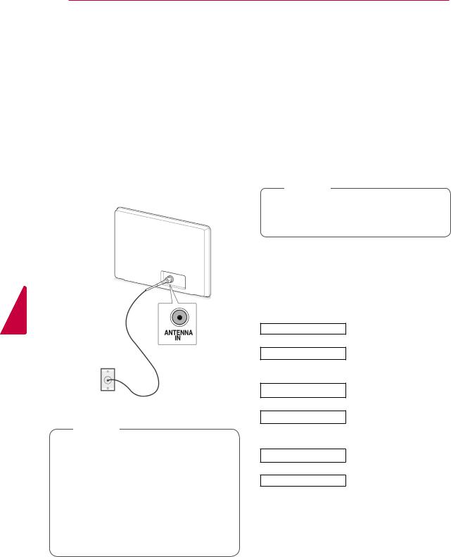
Connecting an antenna
Connect an antenna to watch TV while referring to the following.
To prevent damage do not connect to the mains outlet until all connections are made between the devices.
Connect the TV to a wall antenna socket with an RF cable (75 Ω).
Wall Antenna
Socket
 NOTE
NOTE
yyFor optimum picture quality, adjust antenna direction.
yyIn poor signal areas, to achieve better picture quality it may be necessary to install a signal amplifier to the antenna.
yyIf the image quality is poor with an antenna connected, aim the antenna to the correct direction.
yyAn antenna cable and converter are not supplied.
Turning the TV on for the first time
When you turn the TV on for the first time, the Initial setting screen appears. Select a language and customize the basic settings.
1Connect the Power cord to a power outlet.
2In Standby mode, press (POWER) to turn the TV on.
The Initial setting screen appears if you turn the TV on for the first time.
 NOTE
NOTE
yyYou can also access Factory Reset by accessing OPTION in the main menus.
3Follow the on-screen instructions to customize your TV settings according to your preferences.
Language |
Selects a language to display. |
Mode Setting
Power Indicator
Country
Time Zone
Set Password
Auto Tuning
Selects Home Use for the home environment.
Sets the Power Indicator. (When you select Home Use from Mode Setting - only LED LCD TV)
Selects a country to display. (Depending on model)
Selects the time zone and daylight saving.
(When Russia is selected for Country)
Set the password.
(When France is selected for
Country)
Scans and saves available programmes automatically.
Loading...