

Page 1

MPX G2
Guitar Effects Processor
User Guide
Page 2
Unpacking and Inspection
After unpacking the unit, save all packing materials in case you ever need to ship the unit. Thoroughly inspect the
unit and packing materials for signs of damage. Report any shipment damage to the carrier at once; report
equipment malfunction to your dealer.
Precautions
Save these instructions for later use.
Follow all instructions and warnings marked on the unit.
Always use with the correct line voltage. Refer to the manufacturer's operating instructions for power requirements. Be advised that different
operating voltages may require the use of a different line cord and/or attachment plug.
Do not install the unit in an unventilated rack, or directly above heat producing equipment such as power amplifiers. Observe the maximum
ambient operating temperature listed in the product specification.
Slots and openings on the case are provided for ventilation; to ensure reliable operation and prevent it from overheating, these openings must
not be blocked or covered. Never push objects of any kind through any of the ventilation slots. Never spill a liquid of any kind on the unit.
This product is equipped with a 3-wire grounding type plug. This is a safety feature and should not be defeated.
Never attach audio power amplifier outputs directly to any of the unit's connectors.
To prevent shock or fire hazard, do not expose the unit to rain or moisture, or operate it where it will be exposed to water.
Do not attempt to operate the unit if it has been dropped, damaged, exposed to liquids, or if it exhibits a distinct change in performance indicating
the need for service.
This unit should only be opened by qualified service personnel. Removing covers will expose you to hazardous voltages.
This triangle, which appears on your
component, alerts you to the presence of uninsulated, dangerous voltage inside the enclosure... voltage
that may be sufficient to constitute a
risk of shock.
CAUTION
RISK OF ELECTRIC SHOCK
DO NOT OPEN
This triangle, which appears on your
component, alerts you to important
operating and maintenance instructions in this accompanying literature.
Notice
This equipment generates and uses radio frequency energy and if not installed and used properly, that is, in strict accordance with the
manufacturer's instructions, may cause interference to radio and television reception. It has been type tested and found to comply with the
limits for a Class B computing device in accordance with the specifications in Subpart J of Part 15 of FCC Rules, which are designated to provide
reasonable protection against such interference in a residential installation. However, there is no guarantee that interference will not occur
in a particular installation. If this equipment does cause interference to radio or television reception, which can be determined by turning the
equipment OFF and ON, the user is encouraged to try to correct the interference by one or more of the following measures:
Reorient the receiving antenna
Relocate the computer with respect to the receiver
Move the computer away from the receiver
Plug the computer into a different outlet so that the computer and receiver are on different branch circuits.
If necessary, the user should consult the dealer or an experienced radio/television technician for additional suggestions. The user may find
the following booklet prepared by the Federal Communications Commission helpful:
"How to identify and Resolve Radio/TV Interference Problems."
This booklet is available from the U.S. Government Printing Office, Washington, DC 20402, Stock No. 004-000-00345-4.
Le présent appareil numérique n'émet pas de bruits radioélectriques dépassant les limites applicables aux appareils numériques de la class
B prescrites dans le Règlement sur le brouillage radioélectrique édicté par le ministère des Communications du Canada.
Boss CS-3, Cordovox, Crybaby, DynaComp, Leslie, Maestro, Mu-tron, Octavia, Phase 90, Space Echo, Tube Screamer, Univibe,Vibro Tone
and Vox are trademarked by their respective manuafacturers.
JamMan is a trademark of Lexicon, Inc
.
Copyright 1998 Lexicon Inc.
All Rights Reserved.
Lexicon Inc. • 3 Oak Park • Bedford MA 01730-1441 USA • Telephone 781-280-0300 • Fax 781-280-0490
Lexicon Part # 070-11542
Page 3

Page 4
Dansk
Vigtig information om sikkerhed
Gem denne vejledning til senere brug.
Følg alle anvisninger og advarsler på apparatet.
Apparatet skal altid tilsluttes den korrekte spænding. Der henvises til
brugsanvisningen, der indeholder specifikationer for strømforsyning. Der
gøres opmærksom på, at ved varierende driftsspændinger kan det blive
nødvendigt at bruge andre lednings- og/eller stiktyper.
Apparatet må ikke monteres i et kabinet uden ventilation eller lige over
andet udstyr, der udvikler varme, f.eks. forstærkere. Den maksimale
omgivelsestemperatur ved drift, der står opført i specifikationerne, skal
overholdes.
Der er ventilationsåbninger i kabinettet. For at sikre apparatets drift og
hindre overophedning må disse åbninger ikke blokeres eller tildækkes. Stik
aldrig noget ind igennem ventilationsåbningerne, og pas på aldrig at spilde
nogen form for væske på apparatet.
Dette apparat er forsynet med et stik med jordforbindelse. Denne
sikkerhedsforanstaltning må aldrig omgås.
Udgangsstik fra audioforstærkere må aldrig sættes direkte i apparatet.
Apparatet må ikke udsættes for regn eller fugt og må ikke bruges i
nærheden af vand for at undgå risiko for elektrisk stød og brand.
Apparatet må aldrig bruges, hvis det er blevet stødt, beskadiget eller vådt,
eller hvis ændringer i ydelsen tyder på, at det trænger til eftersyn.
Dette apparat må kun åbnes af fagfolk. Hvis dækslet tages af, udsættes
man for livsfarlig højspænding.
Denne mærkat på komponenten advarer om uisoleret, farlig spænding
i apparatet ... høj nok til at give elektrisk stød.
Denne mærkat på komponenten advarer om vigtig drifts- og
vedligeholdsinformation i den tilhørende litteratur.
Suomi
Tärkeitä turvallisuusohjeita
Säilytä nämä ohjeet tulevaa käyttöä varten.
Seuraa kaikkia yksikköön merkittyjä ohjeita ja varoituksia.
Käytä aina oikeaa verkkojännitettä. Tehovaatimukset selviävät valmistajan
käyttöohjeista. Huomaa, että eri käyttöjännitteet saattavat vaatia
toisenlaisen verkkojohdon ja/tai -pistokkeen käytön.
Älä asenna yksikköä telineeseen jossa ei ole tuuletusta, tai välittömästi
lämpöä tuottavien laitteiden, esim. tehovahvistimien, yläpuolelle.
Ympäristön lämpötila käytössä ei saa ylittää tuotespesifikaation
maksimilämpötilaa.
Kotelo on varustettu tuuletusreiillä ja -aukoilla. Luotettavan toiminnan
varmistamiseksi ja ylilämpenemisen välttämiseksi näitä aukkoja ei saa
sulkea tai peittää. Mitään esineitä ei saa työntää tuuletusaukkoihin. Mitään
nesteitä ei saa kaataa yksikköön.
Tuote on varustettu 3-johtimisella maadoitetulla verkkopistokkeella. Tämä
on turvallisuustoiminne eikä sitä saa poistaa.
Älä kytke audiotehovahvistimen lähtöjä suoraan mihinkään yksikön
liittimeen.
Sähköiskun ja palovaaran välttämiseksi yksikkö ei saa olla sateessa tai
kosteassa, eikä sitä saa käyttää märässä ympäristössä.
Älä käytä yksikköä jos se on pudonnut, vaurioitunut, kostunut, tai jos sen
suorituskyky on huomattavasti muuttunut, mikä vaatii huoltoa.
Yksikön saa avata vain laitteeseen perehtynyt huoltohenkilö. Kansien
poisto altistaa sinut vaarallisille jännitteille.
Tämä kolmio, joka esiintyy komponentissasi, varoittaa sinua
eristämättömän vaarallisen jännitteen esiintymisestä yksikön sisällä.
Tämä jännite saattaa olla riittävän korkea aiheuttamaan
sähköiskuvaaran.
Tämä kolmio, joka esiintyy komponentissasi, kertoo sinulle, että
tässä tuotedokumentoinnissa esiintyy tärkeitä käyttö- ja ylläpitoohjeita.
Norsk
Viktig informasjon om sikkerhet
Ta vare på denne veiledningen for senere bruk.
Følg alle anvisningene og advarslene som er angitt på apparatet.
Apparatet skal alltid anvendes med korrekt spenning. Produktbeskrivelsen
inneholder spesifikasjoner for strømkrav. Vær oppmerksom på at det ved
ulike driftsspenninger kan være nødvendig å bruke en annen ledning- og/
eller støpseltype.
Apparatet skal ikke monteres i skap uten ventilasjon, eller direkte over
varmeproduserende utstyr, som for eksempel kraftforsterkere. Den
maksimale romtemperaturen som står oppgitt i produktbeskrivelsen, skal
overholdes.
Apparatet er utstyrt med ventilasjonsåpninger. For at apparatet skal være
pålitelig i bruk og ikke overopphetes, må disse åpningene ikke blokkeres
eller tildekkes. Stikk aldri noe inn i ventilasjonsåpningene, og pass på at det
aldri søles noen form for væske på apparatet.
Dette apparatet er utstyrt med et jordet støpsel. Dette er en
sikkerhetsforanstaltning som ikke må forandres.
Utgangsplugger fra audioforsterkere skal aldri koples direkte til apparatet.
Unngå brannfare og elektrisk støt ved å sørge for at apparatet ikke utsettes
for regn eller fuktighet og ikke anvendes i nærheten av vann.
Apparatet skal ikke brukes hvis det har blitt utsatt for støt, er skadet eller blitt
vått, eller hvis endringer i ytelsen tyder på at det trenger service.
Dette apparatet skal kun åpnes av fagfolk. Hvis dekselet fjernes, utsettes
man for livsfarlig høyspenning.
Komponenten er merket med denne trekanten, som er en advarsel
om at det finnes uisolert, farlig spenning inne i kabinettet ... høy nok
til å utgjøre en fare for elektrisk støt.
Komponenten er merket med denne trekanten, som betyr at den
tilhørende litteraturen inneholder viktige opplysninger om drift og
vedlikehold.
Svenska
Viktiga säkerhetsföreskrifter
Spara dessa föreskrifter för framtida bruk.
Följ alla anvisningar och varningar som anges på enheten.
Använd alltid rätt nätspänning. Se tillverkarens bruksanvisningar för infor-
mation om effektkrav. Märkväl, att andra matningsspänningar eventuellt
kräver att en annan typs nätsladd och/eller kontakt används.
Installera inte enheten i ett oventilerat stativ, eller direkt ovanför utrustningar
som avger värme, t ex effektförstärkare. Se till att omgivningens temperatur
vid drift inte överskrider det angivna värdet i produktspecifikationen.
Behållaren är försedd med hål och öppningar för ventilering. För att
garantera tillförlitlig funktion och förhindra överhettning får dessa öppningar
inte blockeras eller täckas. Inga föremål får skuffas in genom ventilationshålen.
Inga vätskor får spillas på enheten.
Produkten är försedd med en jordad 3-trådskontakt. Detta är en
säkerhetsfunktion som inte får tas ur bruk.
Anslut aldrig audioeffektförstärkarutgångar direkt till någon av enhetens
kontakter.
För att undvika elstöt eller brandfara får enheten inte utsättas för regn eller
fukt, eller användas på ställen där den blir våt.
Använd inte enheten om den har fallit i golvet, skadats, blivit våt, eller om
dess prestanda förändrats märkbart, vilket kräver service.
Enheten får öppnas endast av behörig servicepersonal. Farliga spänningar
blir tillgängliga när locken tas bort.
Denna triangel, som visas på din komponent, varnar dig om en
oisolerad farlig spänning inne i enheten. Denna spänning är eventuellt
så hög att fara för elstöt föreligger.
Denna triangel, som visas på din komponent, anger att viktiga
bruksanvisningar och serviceanvisningar ingår i dokumentationen i
fråga.
Page 5
Wichtige Sicherheitsanweisungen
Deutsch
Heben Sie sich diese Sicherheitsanweisungen auch für später auf.
Befolgen Sie alle auf der Vorrichtung stehenden Anweisungen und Warnungen.
Immer nur mit der richtigen Spannung verwenden! Die Gebrauchsanweisungen
des Herstellers informieren Sie über die elektrischen Anforderungen.
Vergessen Sie nicht daß bei verschiedenen Betriebsspannungen ggf. auch
verschiedene Leitungskabel und/oder Verbindungsstecker zu verwenden
sind.
Stellen Sie die Vorrichtung nicht in ein unbelüftetes Gestell oder unmittelbar
über wärmeerzeugende Geräte wie z.B. Tonverstärker. Halten Sie die in den
Produktspezifikationen angegebene maximale Umgebungstemperatur bei
Betrieb ein.
Schlitze und Öffnungen im Gehäuse dienen der Belüfung; um verläßlichen
Betrieb sicherzustellen und Überheizen zu vermeiden dürfen diese Öffnungen
nich verstopft oder abgedeckt werden. Stecken Sie nie irgend einen
Gegenstand durch die Belüftungsschlitze. Vergießen Sie keine Flüssigkeiten
auf den Apparat.
Dieses Produkt is mit einem 3-drahtigen Erdungsstecker ausgerüstet. Diese
Sicherheitsmaßnahme darf nicht unwirksam gemacht werden.
Schließen Sie nie Tonverstärker unmittelbar an einen Anschluß des Apparates
an.
Um elektrischen Schlag oder Feuer zu vermeiden, setzen Sie den Apparat
weder Regen noch Feuchtigkeit aus und betreiben Sie ihn nicht dort wo
Wasser eindringen könnte.
Versuchen Sie nicht den Apparat zu betreiben falls er fallen gelassen,
beschädigt, oder Flüssigkeiten ausgesetzt wurde, oder falls sich seine
Arbeitsweise derart ändert daß daraus ein Bedarf nach Raparatur zu schließen
ist.
Dieser Apparat sollte nur von qualifizierten Fachleuten geöffnet werden. Das
Abnehmen von Abdeckungen setzt Sie gefährlichen Spannungen aus.
Dieses Dreieck auf Ihrem Apparat warnt Sie vor nicht-isolierter,
gefährlicher Spannung im Gehäuse ... stark genug um eine
Berührungsgefahr darzustellen.
Dieses Dreieck auf Ihrem Apparat bedeutet daß wichtige Betriebsund Wartungsanweisungen in der mitgelieferten Dokumentation zu
finden sind.
Instrucciones importantes de seguridad
Español
Guarde esta instrucciones para uso posterior.
Utilice siempre el voltaje correcto. Diríjase a las instrucciones de operación
del fabricante para obtener las especificaciones de potencia. Esté al tanto
de que voltajes de operación distintos requieren el uso de cables y/o
enchufes distintos.
No instale esta unidad en un estante sin ventilación, ni tampoco directamente
encima de equipos que generen calor tales como amplificadores de
potencia. Fíjese en las temperaturas ambientales máximas de operación
que se mencionan en las especificaciones del producto.
Las aperturas y ranuras del chasis sirven para proveer la ventilación
necesaria para operar la unidad con seguridad y para prevenir
sobrecalentamiento, y por lo tanto no pueden ser obstruidas o cubiertas. No
introduzca objetos de ningún tipo a través de las ranuras de ventilación, y
nunca deje caer ningún líquido sobre la unidad.
Este producto está equipado con un enchufe de 3 clavijas con conexión a
tierra. Éste es un elemento de seguridad que no debe ser eliminado.
Nunca conecte ningún tipo de salida de amplificadores de sonido directamente
a los conectores de la unidad.
Para prevenir descargas eléctricas o incendios, mantenga la unidad alejada
de la lluvia, humedad o cualquier lugar en el que pueda entrar en contacto
con agua.
No trate de hacer funcionar la unidad si se ha caído, está dañada, ha entrado
en contacto con líquidos, o si nota cualquier cambio brusco en su
funcionamiento que indique la necesidad de hacerle un servicio de
mantenimiento.
Esta unidad deberá ser abierta únicamente por personal calificado. Si usted
quita las coberturas se expondrá a voltajes peligrosos.
Este triángulo que aparece en su componente le advierte sobre la
existencia dentro del chasis de voltajes peligrosos sin aislantes ...
voltajes que son lo suficientemente grandes como para causar
electrocución.
Este triángulo que aparece en su componente lo alerta sobre las
instrucciones de operación y mantenimiento importantes que están
en los materiales de lectura que se incluyen.
Instructions de Sûreté Importantes
Français
Gardez ces instructions pour réference future.
Observez toutes les instructions et tous les avertissements marqués sur
l’appareil.
Branchez uniquements sur un réseau de tension indiquée. Consultez le
manuel d’instruction du fabriquant pour les spécifications de courant.
N’oubliez pas que différentes tensions peuvent nécessiter l’utilisation de
cables et/ou de fiches de connexion différents.
N’installez pas l’appareil en un compartiment non-aéré ou directement audessus d’équipements générateurs de chaleur, tels qu’amplificateurs de
courants, etc. Ne dépassez pas la température ambiante maximale de
fonctionnement indiquée dans les spécifications du produit.
Des fentes et ouvertures sont prévues dans le boîtier pour l’aération; Pour
assurer le bon fonctionnement et pour prévenir l’échauffement, ces ouvertures
ne doivent pas être couvertes ou bloquées. N’insérez pas d’objets dans les
fentes d’aération. Empêchez tout liquide de se répandre sur l’appareil.
Ce produit est muni d’une fiche à trois fils pour la mise à terre. Ceci est une
mesure de sécurité et ne doit pas être contrariée.
Ne connectez jamais d’amplificateurs audio directement aux connecteurs
de l’appareil.
Pour empêcher les chocs électriques et le danger d’incendie, évitez d’exposer
l’appareil à la pluie ou à l’humidité, et ne le mettez pas en marche en un
endroit où il serait exposé aux éclaboussures d’eau.
N’essayez pas de faire fonctionner l’appareil s’il est tombé à terre, a été
endommangé, exposé à un liquide, ou si vous observez des différences
nettes dans son fonctionnement, indiquant la nécessité de réparations.
Cet appareil ne doit être ouvert que par un personnel de service qualifié. En
enlevant les couvercles vous vous exposez à des tensions électriques
dangereuses.
Ce triangle, sur votre appareil vous avertit de la présence de tension
dangereuse, non-isolée à l’intérieur du boîtier...une tension suffisante
pour représenter un danger d’électrocution.
Ce triangle sur sur votre appareil vous invite de suivre d’importantes
instructions d’utilisation et d’entretien dans la documentation livrée
avec le produit.
Importanti norme di sicurezza
Italiano
Conservare le presenti norme per l’utilizzo futuro.
Osservare tutte le istruzioni e le avvertenze apposte sull’unità.
Utilizzare esclusivamente con la tensione di rete corretta. Consultare le
istruzioni operative fornite dal fabbricante per i dati riguardanti la tensione e
l’assorbimento di corrente. Potrebbe essere necessario l’uso di cavi di rete
e/o di spine diverse a seconda della tensione utilizzata.
Non installare l’unità in uno scaffale privo di ventilazione oppure direttamente
sopra una fonte di calore, come, ad esempio, un amplificatore. Non superare
la temperatura ambientale massima di funzionamento riportata nei dati
tecnici del prodotto.
Le fessure e le altre aperture nella scatola servono alla ventilazione. Per un
funzionamento affidabile, e per evitare un eventuale surriscaldamento,
queste aperture non vanno ostruite o coperte in nessun modo. Evitare in tutti
i casi di inserire oggetti di qualsiasi genere attraverso le fessure di ventilazione.
Non versare mai del liquido di nessun tipo sull’unità.
Questo prodotto viene fornito con una spina a 3 fili con massa. Tale
dispositivo di sicurezza non va eliminato.
Evitare sempre di collegare le uscite dell’amplificatore audio direttamente ai
connettori dell’unità.
Per prevenire il pericolo di folgorazione e di incendio non esporre l’unità alla
pioggia o ad un’umidità eccessiva; evitare di adoperare l’unità dove potrebbe
entrare in contatto con acqua.
Evitare di adoperare l’unità se la stessa è stata urtata violentemente, se ha
subito un danno, se è stata esposta ad un liquido o in caso di un evidente
cambiamento delle prestazioni che indichi la necessità di un intervento di
assistenza tecnica.
Ogni intervento sull’unità va eseguito esclusivamente da personale qualificato.
La rimozione della copertura comporta l’esposizione al pericolo di
folgorazione.
Il presente triangolo impresso sul componente avverte della presenza
di tensioni pericolose non isolate all’interno della copertura... tali
tensioni rappresentano un pericolo di folgorazione
Il presente triangolo impresso sul componente avverte l’utente della
presenza nella documentazione allegata di importanti istruzioni relative
al funzionamento ed alla manutenzione.
Page 6

Introduction
1. Product Overview
The Front Panel .................................................................................. 1-1
The Rear Panel................................................................................... 1-2
Installation Notes ................................................................................ 1-3
Mounting ...................................................................................... 1-3
Power Requirements.................................................................... 1-3
Quick Start .......................................................................................... 1-3
Stand alone .................................................................................. 1-4
Amp Input Only ............................................................................ 1-5
Amp Input & FX Loop ................................................................... 1-6
Connecting Other Equipment ............................................................. 1-8
Signal Flow ....................................................................................... 1-10
Digital Audio Paths ........................................................................... 1-11
Internal Grounding ............................................................................ 1-11
Unbalanced Connections.................................................................. 1-11
Guitar Input ....................................................................................... 1-11
Main Outputs .................................................................................... 1-11
Insert Send ....................................................................................... 1-12
Insert Returns ................................................................................... 1-12
Automatic Insert Return Signal Routing............................................ 1-12
Right (Mono) Only ..................................................................... 1-12
Stereo......................................................................................... 1-12
Left Only ..................................................................................... 1-12
Connecting the main Outputs to Mono Input .................................... 1-13
Setting Audio Levels ......................................................................... 1-13
Using Soft Sat................................................................................... 1-13
Input Level and Clip Indicators ......................................................... 1-13
Aux In and Clip Indicators ................................................................. 1-13
Contents
Look here for connector
information and Quick
Start configurations
2. Basic Operation
MPX G2 Menus .................................................................................. 2-1
Loading and Playing with Programs ................................................... 2-2
Program Load .............................................................................. 2-2
Effect Bypass ............................................................................... 2-3
Insert Bypass ............................................................................... 2-3
Dedicated Analog Controllers ...................................................... 2-3
Programmable Bypass Modes ..................................................... 2-4
Tuner ............................................................................................ 2-4
Tap ............................................................................................... 2-4
A/B ............................................................................................... 2-5
Soft Row Editing ................................................................................. 2-5
Using the DataBase............................................................................ 2-6
Program Store .................................................................................... 2-7
Easy operation of the
MPX G2 — loading, playing
with, and storing programs.
Page 7

Contents, cont'd.
Check here for information
on editing Effects and
programs.
3. Editing
Effect Editing ...................................................................................... 3-1
The MPX G2 Edit Menus .................................................................... 3-3
Mix ............................................................................................... 3-4
Adjusting Pre-Gain and Post-Gain Level ............................... 3-4
Speaker Sim................................................................................. 3-5
Automatic Speaker Sim Routing............................................ 3-6
Noise Gate ................................................................................... 3-7
Meters .......................................................................................... 3-8
Effect Order.................................................................................. 3-9
Routing Map............................................................................... 3-10
How to Change Routing Connections.................................. 3-12
How to Change Routing Options ......................................... 3-12
Routing Examples................................................................ 3-13
Notes and Tips on Routing .................................................. 3-16
Patching (See Chapter 4)........................................................... 3-16
Controllers (Knob, LFO 1 and 2, Random, A/B and Env ) ......... 3-17
Tempo ........................................................................................ 3-18
Rate ..................................................................................... 3-18
Source ................................................................................. 3-18
Beat Value ........................................................................... 3-19
Tap Source .......................................................................... 3-19
Compare .................................................................................... 3-19
Soft Row Parameter Assignment ............................................... 3-20
DataBase Assignmments ........................................................... 3-20
Copy Effect................................................................................. 3-22
All about the MPX G2
Patch System
Complete details on all
of the MPX G2 System
parameters
4. Patching
Selecting a Source and Destination.................................................... 4-2
Changing the Range of the Source Controller .................................... 4-3
Viewing Source Controller Activity ............................................... 4-3
MIDI Learn — Automatic Controller Assignment ......................... 4-4
Copying Patches ................................................................................ 4-4
Changing the Range of the Destination Parameter ............................ 4-5
Linear or Nonlinear Control .......................................................... 4-6
Suspending and Clearing Patches ..................................................... 4-7
Multiple Patches with the Same Destination....................................... 4-7
5. System Controls
The System Menus............................................................................. 5-1
Audio Controls .................................................................................... 5-1
Soft Sat ........................................................................................ 5-1
Output Mode ................................................................................ 5-1
Modes ............................................................................................... 5-2
Pgm Load..................................................................................... 5-2
Mix ............................................................................................... 5-2
Send Bypass ................................................................................ 5-2
Pgm Bypass ................................................................................. 5-2
Tempo Mode ................................................................................ 5-3
Memory Protect............................................................................ 5-3
Brightness .................................................................................... 5-3
Sleep ............................................................................................ 5-3
Post Bypass ................................................................................. 5-4
Page 8

Insert ............................................................................................ 5-4
FX Loop ................................................................................. 5-4
Mix ......................................................................................... 5-4
Parallel................................................................................... 5-4
Setup Load and Setup Store ........................................................ 5-5
MIDI ............................................................................................... 5-7
Program Change/Options: Pgm# Offset, Pgm+ and Pgm- .......... 5-7
Receive ........................................................................................ 5-7
Transmit ....................................................................................... 5-7
Ctl Send/Options: MIDI Reset ...................................................... 5-8
Ctl Smooth ................................................................................... 5-8
Clock Send................................................................................... 5-8
Automation/Options: Xmit Device ID ............................................ 5-9
SysEx/Options: Receive Device ID .............................................. 5-8
Soft Thru ...................................................................................... 5-9
Dump/Options: Xmit Speed.......................................................... 5-9
MIDI Maps ........................................................................................ 5-10
Program Chains................................................................................ 5-11
Initialize............................................................................................. 5-12
Clear Programs................................................................................. 5-13
Copy Programs................................................................................. 5-14
Global Patches/Options: MIDI Learn and Dst Edit............................ 5-15
Calibrate Pedal ................................................................................. 5-16
Bypass Patches ................................................................................ 5-16
Tuner Mode ...................................................................................... 5-17
Global Effects ................................................................................... 5-17
Speaker Sim Mode..................................................................... 5-18
Noise Gate Mode ....................................................................... 5-18
Reverb Mode.............................................................................. 5-18
Bypass Mode ............................................................................. 5-18
Contents, cont'd.
6. MIDI Operation
Selecting a MIDI Channel ................................................................... 6-1
Accessing Programs........................................................................... 6-1
Controlling MPX G2 Tempo Rate with MIDI Clock ............................. 6-2
MIDI Tempo Control ..................................................................... 6-2
Using the MPX G2 as a MIDI Clock Source................................. 6-2
Slaving two or more MPX G2s ..................................................... 6-3
Controller Quirks................................................................................. 6-4
The Knob, Footpedal and Footswitch as MIDI Controllers ................. 6-4
Program Change Messages ............................................................... 6-5
Automation ......................................................................................... 6-6
SysEx Automation........................................................................ 6-6
Controller Automation .................................................................. 6-6
Reset All Controllers .................................................................... 6-6
MIDI Clock and Clock Commands ............................................... 6-6
Dynamic MIDI............................................................................... 6-7
Bulk Data Dumps................................................................................ 6-7
MIDI Implementation Chart................................................................. 6-8
Information on working
with MIDI
Page 9

Contents, cont'd.
Complete details on all
of the MPX G2 Effects
7. The Effects and Parameters
Notes on Combining Effects ............................................................... 7-2
Notes on Controlling Effect Parameters ............................................. 7-2
Notes on the Effect Descriptions ........................................................ 7-2
Gain Effects ........................................................................................ 7-3
Tone ............................................................................................. 7-3
Crunch.......................................................................................... 7-3
Screamer...................................................................................... 7-4
Overdrive...................................................................................... 7-5
Distortion ...................................................................................... 7-6
Preamp and SplitPreamp ............................................................. 7-6
Effect1 and Effect2 ............................................................................. 7-8
Detune (M), Detune (S) and Detune (D) – Effect1 only................ 7-8
Shift (M), Shift (S) and Shift (D) – Effect1 only............................. 7-9
DiatonicHmy – Effect1 only ........................................................ 7-10
Panner........................................................................................ 7-11
Auto Pan .................................................................................... 7-11
Tremolo (M) and Tremolo (S)..................................................... 7-12
UniVybe...................................................................................... 7-12
CustomVybe............................................................................... 7-13
Phaser........................................................................................ 7-13
OrangePhase ............................................................................. 7-14
Red Comp .................................................................................. 7-14
Blue Comp ................................................................................. 7-15
DigiDrive1 and DigiDrive2 .......................................................... 7-15
OctaBuzz.................................................................................... 7-16
SweepFilter ................................................................................ 7-17
1-Band (M) ................................................................................. 7-17
Wah 1, Wah 2 and PedalWah1, PedalWah2 ............................. 7-18
Volume (M), Volume (S) and Volume (D) .................................. 7-19
PedalVol and ExtPedalVol ......................................................... 7-19
Test Tone ................................................................................... 7-20
Click ........................................................................................... 7-20
Chorus Effects .................................................................................. 7-21
Chorus........................................................................................ 7-21
Detune (M) ................................................................................. 7-22
Flanger (M), Flanger24 (M) and Flanger (S) .............................. 7-23
Rotary Cab ................................................................................. 7-24
Aerosol ....................................................................................... 7-24
Orbits.......................................................................................... 7-25
Centrifuge1 and Centrifuge2 ...................................................... 7-26
Comb 1 and Comb 2 .................................................................. 7-27
Volume (M), Volume (S) and Volume (D) .................................. 7-28
PedalVol and ExtPedalVol ......................................................... 7-28
Delay Effects .................................................................................... 7-29
Delay (M), Delay (S) and Delay (D) ........................................... 7-30
Echo (M), Echo (S) and Echo (D) .............................................. 7-31
Looper ........................................................................................ 7-32
JamMan ..................................................................................... 7-33
Ducker........................................................................................ 7-34
Page 10
Reverb Effects .................................................................................. 7-35
Chamber .................................................................................... 7-35
Hall ............................................................................................. 7-35
Plate ........................................................................................... 7-36
Ambience ................................................................................... 7-36
Gate ........................................................................................... 7-37
EQ Effects ........................................................................................ 7-38
1-Band (M), 2-Band (M), 3-Band (M) and 4-Band (M) ............... 7-40
1-Band (S) and 2-Band (S) ........................................................ 7-40
1-Band (D) and 2-Band (D) ........................................................ 7-41
Fc Splitter ................................................................................... 7-41
Crossover ................................................................................... 7-42
Volume (M), Volume (S) and Volume (D)................................... 7-42
PedalVol and ExtPedalVol ......................................................... 7-43
8. MPX G2 Internal Controllers
Knob ............................................................................................... 8-1
LFO1 and LFO2.................................................................................. 8-1
Random Generator ............................................................................. 8-2
A/B Glide ............................................................................................ 8-2
Env ............................................................................................... 8-3
Footswitch Controllers ........................................................................ 8-3
9. Program Descriptions
1-99: Amp Input + FX Loop ................................................................ 9-1
100-149: Amp Input Only .................................................................. 9-15
150-248: Stand Alone ....................................................................... 9-20
249-250: Utility (All configurations: Unity Gain and Clean Slate) ...... 9-30
Contents, cont'd.
Complete descriptions of
the MPX G2 Internal
controllers
Complete descriptions of
the MPX G2 programs
10. Troubleshooting
Low Voltage ...................................................................................... 10-1
Overheating ...................................................................................... 10-1
Common MIDI Problems .................................................................. 10-1
Power On Behavior........................................................................... 10-2
11. Specifications
Check here for solutions
to common problems
Page 11

Foreword
When we started development on the MPX G2 Guitar Effects Processor and the
MPX R1 MIDI Remote Controller, we knew we were designing for the most
discriminitating guitarists — players whose tonal foundation is based on this nocompromise equation:
great guitar + great amp = great tone
Our challenge was to put together a guitar effects system that could mesh with
your favorite gear and not get in the way of your signature sound. Since we had
no intention of trying to duplicate the “great amp” portion of the equation inside
of our effects processor, we needed to make the MPX G2 capable of putting
effects in two places at the same time — between the guitar and your amp (like
stomp boxes) or in your amp’s effects loop (like rack effects). Add to that the
challenge of getting the sounds right, and combining analog and digital effects
in a roadworthy package, and you’re definitely into something totally new.
So, here it is. A lot of people have put a lot of sweat into this box so you could
do what you do best — so get out there and play.
Throughout the development process of our Custom Shop products, we’ve
had the help of a team of artist advisors. Time and again their input had a
major impact on both the MPX G2 Guitar Effects Processor and MPX R1 MIDI
Remote Controller. Some were with us at the beginning, when these products
were just concepts on paper, others joined us as various prototypes came
roaring to life.
Jon Finn, Dave Friedman of Rack Systems Ltd., Michael James, Eddie
Kramer, Peter McCabe of Tone King Studio, John McIntyre, Bobby Owsinski,
John Petrucci, Blues Saraceno, Alex Saraceno, David Torn and Carl
Verheyen — each made significant contributions, including:
putting their reputations on the line by working with experimental
gear in front of large paying audiences — or in critical sessions with
the clock ticking, so that we could evaluate under real-world conditions.
sharing secrets, tips and tricks — “How did you get that sound on
(insert hit tune from platinum record)?”
spending hours and hours of critical listening time to help us
evaluate our work as it progressed, and letting us know when we had
to go back to the drawing board.
Thanks to each of you for applying your consummate skills to this project.
Your faith, encouragement, enthusiasm and patience helped us get it right.
Page 12
Thank you for your purchase of the MPX G2 Guitar Effects Processor. The MPX
G2 works with any amp, from combo to stack, allowing you to place authentic
effects anywhere in the signal chain without altering the amps basic tone. Two
separate signal paths allow you to place effects where you want them. For
example compression, wah and analog overdrive can be placed in front of the
amp, while other effects, like delay chorus and reverb might be placed in the
amps effect loop.
Dynamic Gain™, Lexicon’s new analog distortion technology provides screaming overdrive and warm distortion tones which can be used as an analog stomp
box in front of your amp or as a stand alone preamp for direct recording or live
performance.
Seven primary effect types: Gain, Effect 1, Effect 2, Chorus, Delay, EQ and,
Reverb give you push button access to 76 effects, including extraordinary
recreations of classics like the Uni-Vibe®, Dyna-Comp®, Phase 90®, Vox® and
Cry Baby® wah, intelligent pitch shift, a JamMan™ style looper with 20-second
full bandwidth delays, Chorus, Flanger, Sweepfilter, Detuner, Rotary Speaker,
Parametric EQ and Tremolo.
The preset library is organized under database control to allow you to quickly
find programs designed for specific styles such as Rock, or Blues, to find all of
the programs using certain effects such as Overdrive, or to find only programs
suitable for Stand Alone operation.
Visual feedback is available every step of the way when you're using the
MPX G2, with lighted buttons indicating the state of the unit and alerting you to
extra features available from the front panel. A large numeric display shows
program (and patch) numbers. A second alphanumeric display shows you
program and parameter names and settings.
Like all Lexicon processors, the MPX G2 gives you as much depth of control as
you're ever likely to want, while keeping the details out of your way. Surface
control of the MPX G2 is straightforward and intuitive, with the most useful
parameters of every program available from a dedicated Soft Row button on the
front panel.
The MPX G2 gives you tap tempo control when you want it. You can assign
tempo control to modulation rates, delay times or any effect parameter, ensuring
that your effects are in tempo with your music. Tempos can be tapped in with the
front panel Tap button (or an assigned controller) or “dialed-in”, in BPM (beats
per minute) on the display. The MPX G2 also lets you generate MIDI clock from
your tempo, as well as receive MIDI tempo from an external sequencer or drum
machine. Many presets have delay times assigned to Tap tempo. When you
load a tempo driven program, the front panel Tempo LED will flash at the current
tempo to let you know the Tap button is active. Press Tap twice in rhythm to
change tempo.
Introduction
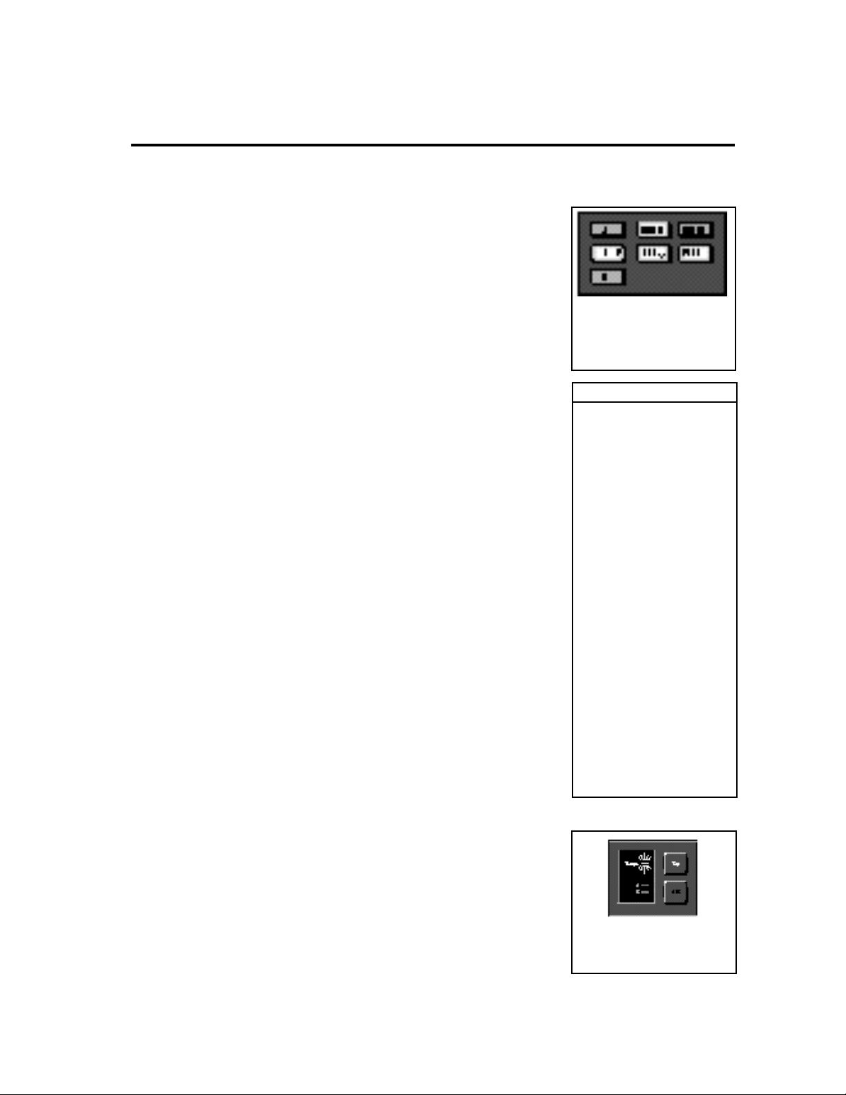
Effect buttons light to show you
which are active in any program.
Push any lighted effect button to
instantly bypass the effect. Press it
again to turn the effect back on.
Database Sorting Options
Sort selections by:
name
number
Guitar Style:
Bass
Blues
Clean
Country
Jazz
Rock
Effect type:
Chorus
Delay
Distortion
EQ
Flanger
Gain
Mod
Overdrive
Phaser
Pitch
Reverb
SpkrSim
Wah
All
App type:
StndAlne
Amp In
FX Loop
members of MIDI maps
members of pgm chains
last 10 programs loaded
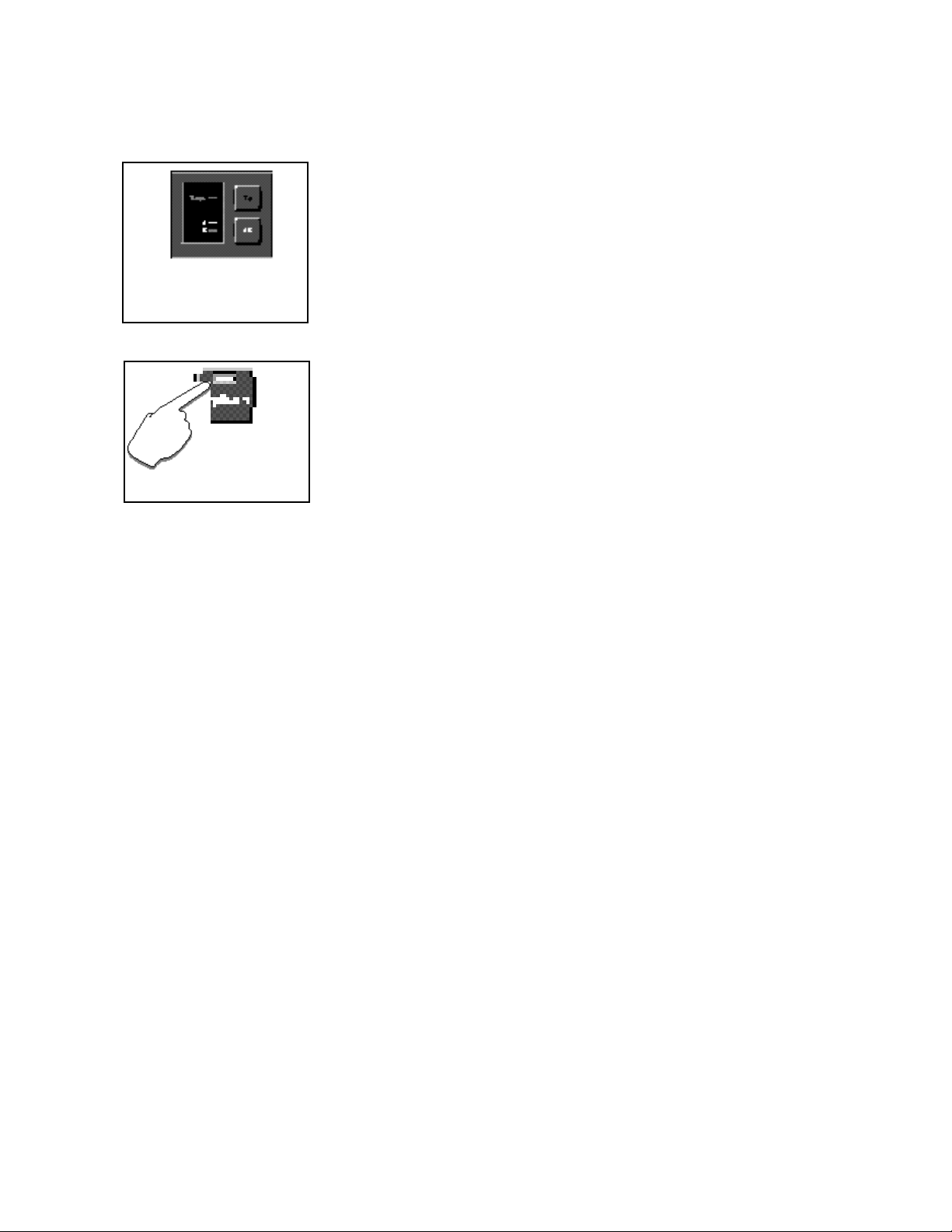
The Tempo light will flash in tempo
whenever the Tap button is active.
Press Tap twice in rhythm to match
the tempo of effects to your music.
Page 13
The A or B LED will light whenever a
program with A/B Glide is loaded.
Press A/B to activate a parameter
glide whenever these lights are lit.
Many features
are brought out under
the Options button – which
will light whenever options are
available.
An A/B glide function is also available from the front panel — and of course we've
designed presets to show this function off to its fullest. Whenever the A or B LED
is lit, press the A/B button to activate the glide.
When you want to create your own versions, you'll find A/B available as an
internal controller in Edit mode along with two LFOs, an Envelope, and more.
Complete editing control is provided under the Edit button, where you can
customize presets or make new ones from scratch, design your own soft row
parameters, copy effects into new programs, and put effects in any sequence
or routing configuration you want. Easy access to all of the parameters of any
effect is just a button push away.
All of the front panel functions (Tap, A/B, Effect selection, etc.) can easily be
connected to MIDI controllers, footswitches, or footpedals, letting you set up all
of the functions the way you want them.
About the manual
To get the most out of the MPX G2, we suggest that you invest the time to explore
this manual. We think you’ll agree that the time spent investigating will reward
you with enjoyment of its full capabilities.
To get off to a quick start, turn directly to Chapter 1 Product Overview and
Chapter 2 Basic Operation. The first section provides button definitions and
necessary information for setting audio levels and connecting to other equipment. The second will tell you everything you need to know about loading and
playing with programs.
When you want to know more, check out the Table of Contents. We've divided
topics into many easy to read (or skip) chapters so that you can find what you
need without wading through what you don't.
Page 14
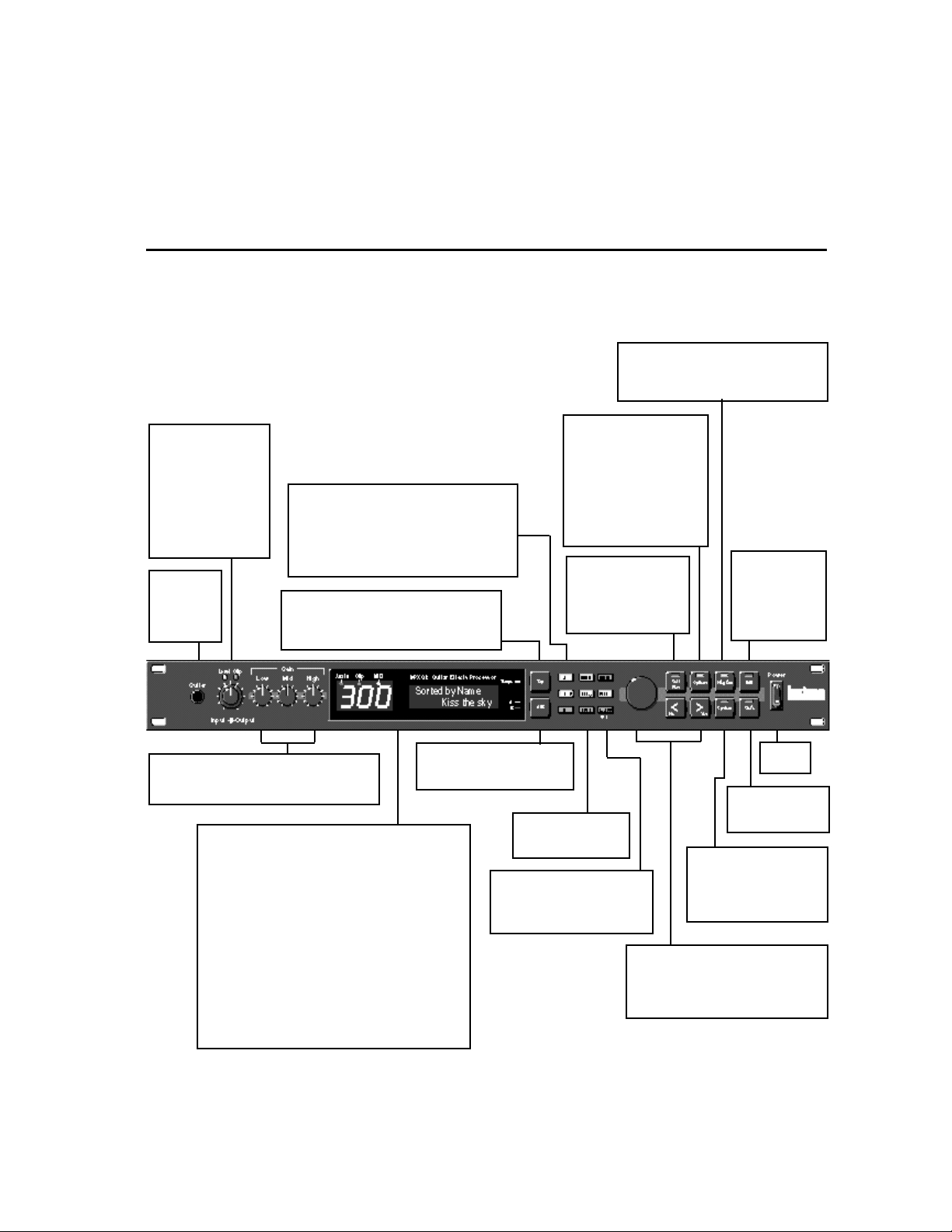
Input/Output
Dual-function knob
controls input and output levels.
Level and Clip LEDs
indicate presence of
signal and overload
(input signal greater
than -0.1dB).
Guitar
Guitar input.
(o ver r ide s
rear panel input.)
Effect Select: Gain, Effect1, Effect2,
Chorus, Delay, Reverb, EQ
Buttons light to indicate effect is active. In
Program mode, pressing button turns off LED
and bypasses effect. In Edit mode, pressing
button selects effect parameters for editing.
Tap
When Tempo LED is flashing, sets tempo.
Press twice in rhythm to establish tempo
rate. Press once to reset LFO.
Product Overview
The Front Panel
Program*
Activates Program Mode where you can
select and load programs and see which
effects are active in any program.
Options
LED lights to indicate options exist for the displayed
parameter. Press to access
options. (LED will flash
while options are displayed.) Press again to exit.
In Program mode, accesses
DataBase sorting selection.
Soft Row
Press at any time for
instant access to key
editing parameters for
the current program.
Product Overview
1
*In Autoload (default),
displayed programs
load automatically. In
Manual mode, press
Program to load any
displayed program.
Edit
Activates Edit
mode for access
to all parameters
of the currently
loaded effect.
Low, Mid, High
Bass, midrange and treble gain controls for
the Gain effect in the current program.
Display
Aux In LED lights to indicate presence of signal at the
Aux Input. The green Clip LED lights to indicate over-
load at the Aux Input. The MIDI LED lights to indicate
incoming or outgoing MIDI data.
3-Digit Display indicates ID number of currently loaded
program, patch or tuner value.
Two rows of 16 characters display program and effect
names, parameter names and values, help and alert
messages and tuner information. An edit indicator
shows edited effects.
Tempo LED flashes in time with current tempo rate
when Tap is active.
A/B LEDs light to indicate A/B function is active.
A/B
Activates a variable glide between patched parameters.
Insert
Activates or bypasses
the Insert.
Bypass
Bypasses currently loaded
program. When held, activates
the built-in tuner.
Power
On/Off.
Store
Initiates program
store function.
System
Activates System mode
parameters such as auto or
manual load, MIDI dumps,
I/O configuration, etc.
Knob and < >
Knob selects programs, <and > adjust
the displayed parameter's value and
enter Yes and No responses to screen
queries.
1-1
Page 15
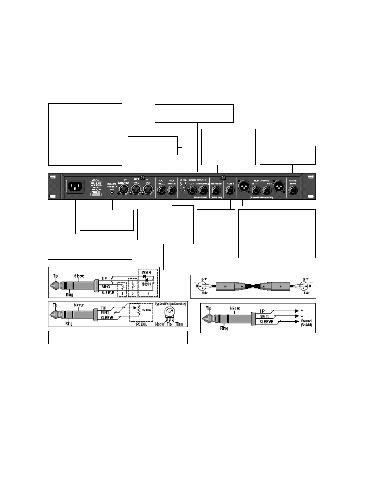
The Rear Panel
LexiconMPX G2 User Guide
MIDI
IN
7-pin DIN connector for MIDI IN or
powered bidirectional MIDI remote.
THRU
5-pin DIN connector passes any
MIDI data received without change.
OUT
5-pin DIN connector transmits MIDI
data to other equipment.
REMOTE POWER IN
2.5mm connector for 9
VAC MIDI remote power.
AC Power
Standard 3-pin IEC power connector.
100-240V, 50-60Hz automatic switching
to correct voltage range.
Insert Returns (from Preamp)
When connected, external audio will
be inserted after the Gain block.
Insert Returns Level
Controls the input level
of the Insert Returns.
Foot Pedal
1/4" Tip/Ring/Sleeve
phone jack provided for
footpedal with 10kΩ to
100kΩ impedance.
Foot Switch
1/4" Tip/Ring/Sleeve phone
jack for three independent
footswitches.
Insert Send (to Preamp)
When the Insert Returns
are connected, all effects
before (and including) the
Gain block will be passed
to this connector.
Phones
Headphone input.
Guitar Input
Guitar input (overridden by
front panel input.)
Main Outputs (to Power Amp or
Console)
XLR and 1/4" TRS: Output impedance
is 600Ω, each side, balanced, and
levels up to +18dBu maximum full
scale.
Unbalanced output levels up to
+21dBu into 100kΩ.
For control voltage input, use a 1/4" stereo plug with Sleeve connected
to ground, Tip connected to the control voltage, and Ring unconnected.
1-2
Page 16
Product Overview
Installation Notes
The MPX G2 uses one EIA-standard rack space, and can be mounted on any
level surface or in a standard 19 inch (483 mm) rack. If the unit is mounted in a
rack or road case, support the rear of the chassis to prevent possible damage
from mechanical shock and vibration.
The maximum ambient operating temperature is 104°F (40°C). Provide adequate ventilation if the unit is mounted in a closed rack with heat-producing
equipment such as power amplifiers.
The MPX G2 is equipped with a 3-pin IEC power connector and detachable
cord. The unit will operate with power sources from 100 to 240 volts AC, 5060Hz. Power switching to actual line voltage is automatic.
You’re here because you want to play with the MPX G2 RIGHT NOW. Plenty of
time to read the manual later right?
OK. First things first. If the MPX G2 isn’t fresh out of the box, let’s make sure that
all of the internal parameters are set to their original factory settings. (This won’t
affect any user programs.)
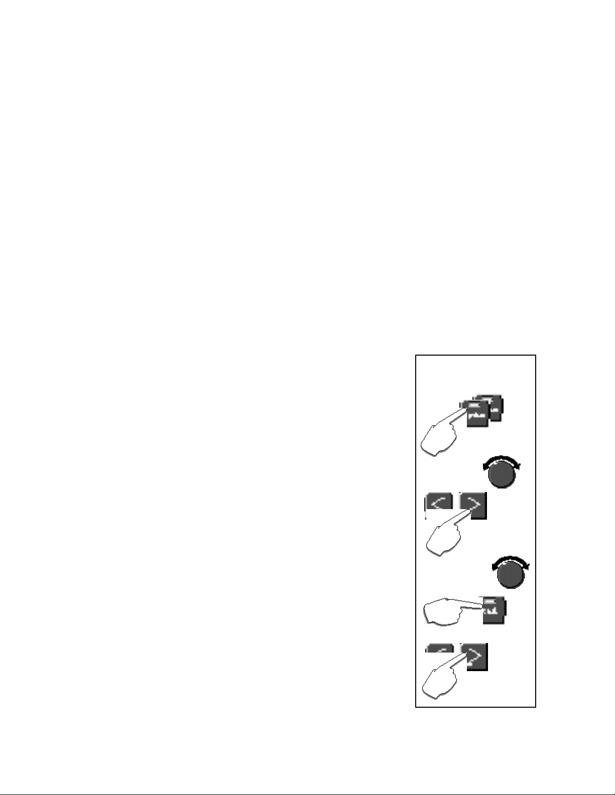
1. Press System twice.
2. Use the knob to select Initialize.
3. Press > to display All.
4. Use the knob to select System Only.
5. Press Store.
6. The display will show: Are you sure?/Yes or No.
7. Press Yes.
Mounting
Power Requirements
Quick Start
Reset the MPX G2 to its
factory settings
(User programs are not affected.)
Press System twice.
Use the knob to
select Initialize.
What happens next depends on how you want to connect and use the MPX G2.
Setups for of the three basic configurations is covered in the following pages.
• Stand Alone: connected directly to headphones, mixer or power amp
• Amp Input Only: connected to a guitar amp that does not have an effects loop
• Amp Input & FX Loop: connected to a guitar amp that has a mono or stereo
effects loop
Each application has its own set of programs — so be sure to listen to the
programs that match the application.
Press > to select All.
Use the knob to select
System Only.
Press Store.
Press Yes in response
to the display prompt..
1-3
Page 17
LexiconMPX G2 User Guide
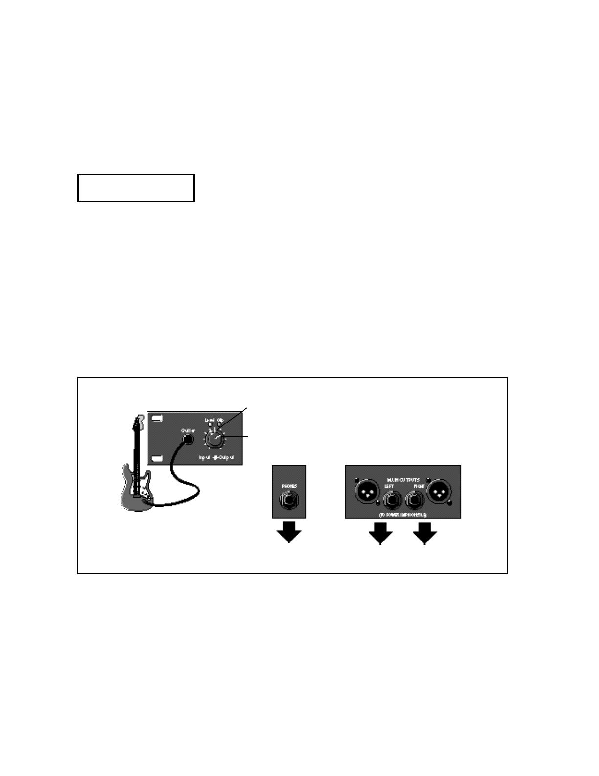
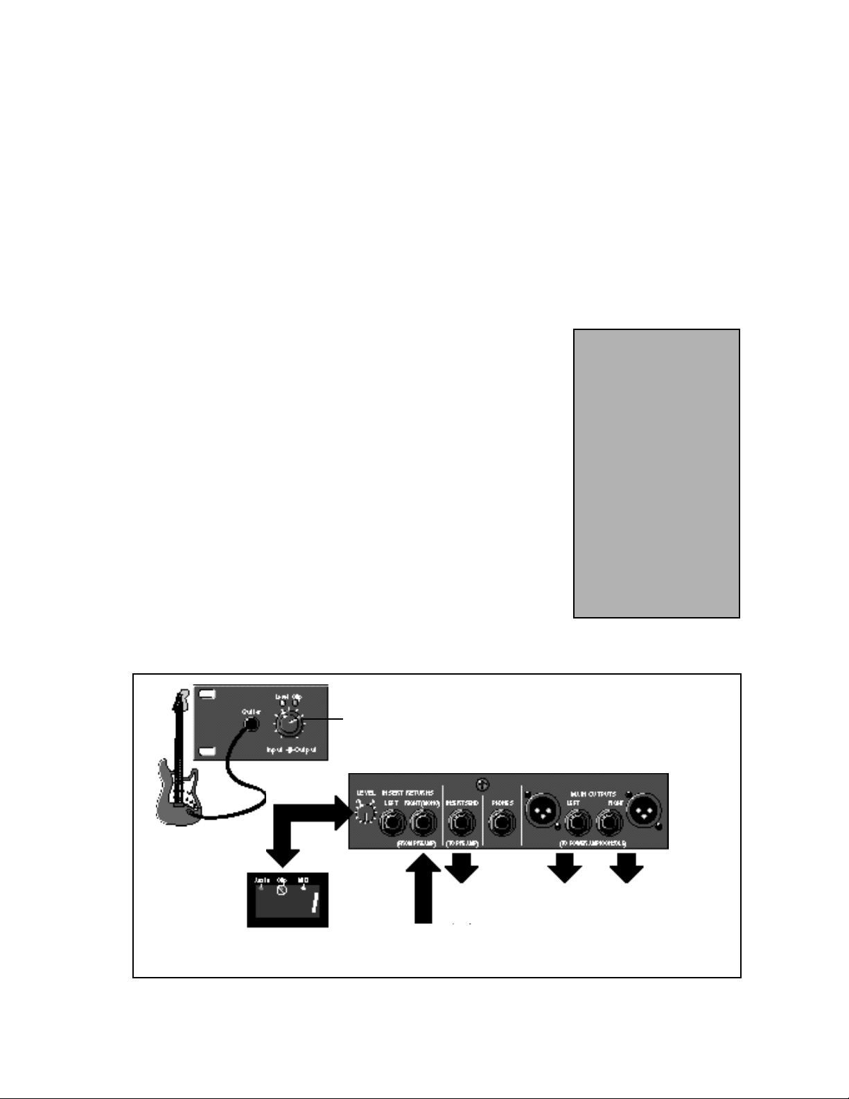
Stand Alone:
Direct connection to
headphones, mixer or
power amp
Use with
Programs 150-250
Front Panel
1. Turn the front panel Output control all the way down
2. Connect the Left and Right outputs to two input channels of your mixer or
power amp
OR
Connect a pair of stereo headphones to the rear panel Phones jack
3. Connect your guitar to the MPX G2 front panel Guitar input
4. Set the MPX G2 front panel Input knob to 2 o’clock.
5. Select your guitar’s most powerful pickup, turn the guitar volume control up
all the way and play your loudest.
6. Watch the Level and Clip LEDs above the MPX G2 Input/Output knob. If the
red Clip LED comes on more than just occasionally during your very loudest
playing, back off the Input knob a bit. (With some guitars, the red LED may
never come on — that’s OK.) Now that you’ve got the Input knob set for your
loudest playing, feel free to change the controls of your guitar to any settings
you like as you audition the MPX G2.
7. While playing, slowly turn up the front panel Output knob until you reach a
comfortable listening level. (You will hear a slight ticking as this knob is
adjusted — this is normal.)
Now you’re ready to start listening to the Stand Alone programs (150-250).
Turn Output to a comfortable
listening level.
1-4
Turn Input to 2 o'clock.
Rear Panel
OR
to stereo headphones to Left and Right inputs of a
mixer or power amp
Page 18
Product Overview
1. Load MPX G2 program 249 Unity Gain.
2. Plug your guitar directly into your amp and set the guitar volume to a
comfortable listening level.
3. Put your amp on standby — or turn it off.
4. Unplug your guitar from the amp and connect the MPX G2 rear panel Send
jack to the input of your guitar amp.
5. Connect your guitar to the MPX G2 front panel Guitar input.
6. Set the MPX G2 front panel Input knob to 2 o’clock.
7. Select your guitar’s most powerful pickup, turn the guitar volume control up
all the way and play your loudest.
8. Watch the Level and Clip LEDs above the MPX G2 Input/Output knob. If
the red Clip LED comes on more than just occasionally during your very
loudest playing, back off the Input knob a bit. (With some guitars, the red
LED may never come on — that’s OK.) Now that you’ve got the Input knob
set for your loudest playing, feel free to change the controls of your guitar
to any settings you like as you audition the MPX G2.
9. Press Bypass to bypass the program. (The Bypass LED will turn on.)
10 Take your amp out of standby (or turn it on) and play. The volume and tone
of the guitar should be the same as when you were plugged directly into the
amp, thanks to the MPX G2 built-in relay bypass.
11. Press Bypass again to make the program active. (The Bypass LED will
turn off). Play and compare this level with the bypassed level — they should
be very close.
12. With the program active, adjust the position of the MPX G2 Input knob to
match the bypassed loudness.
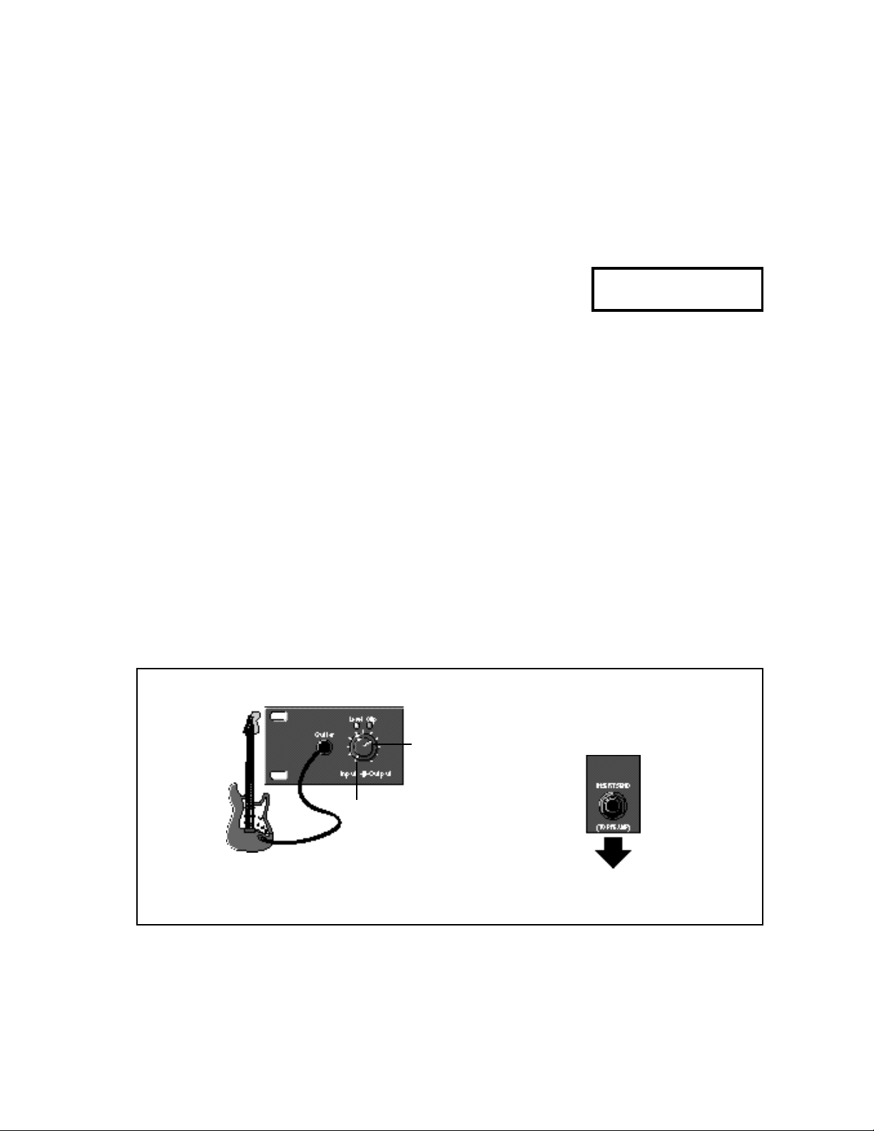
Amp Input Only:
Connection to a guitar
amp that doesn’t have an
effects loop
Use with
Programs 100-149
Now you’re ready to start listening to the Amp Input Only programs (100-149).
Front Panel
Turn Input to 2 o'clock.
The Output control is unnecessary
when the MPX G2 is used with an amp
that doesn't have an effects loop.
to the guitar amp Input
(the same input you would
use to plug in your guitar)
Rear Panel
1-5
Page 19
LexiconMPX G2 User Guide
Amp Input & FX Loop:
Connection to a guitar
amp with a mono or
stereo effects loop
Use with
Programs 1-99
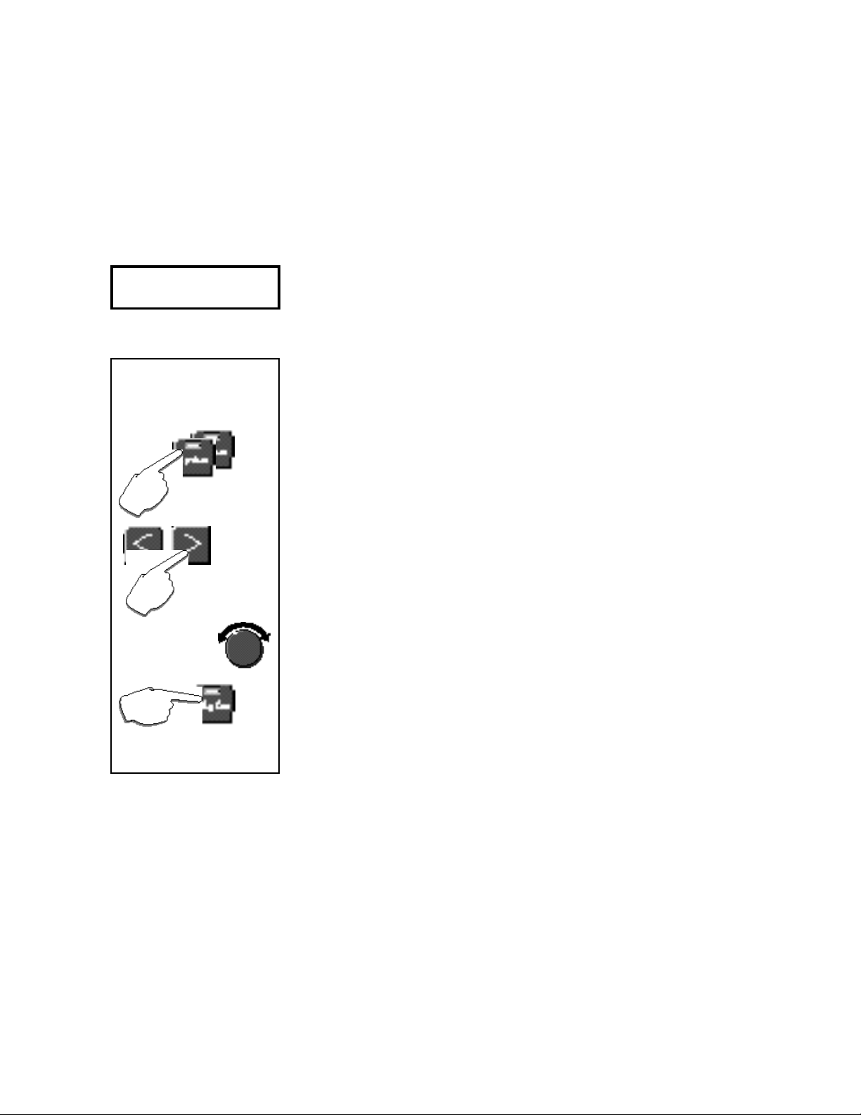
Seting the MPX G2
Main Outputs to Mono
(for guitar amps with a mono
effects loop)
Press System twice.
Press > to select
Audio Output Mode.
Use the knob to
change the setting
from Stereo to Mono.
Press Program to return
to Program Mode.
This is a bit more detailed than Stand alone or Amp Input Only setup — you’ll
be connecting the MPX G2 to both sides of your guitar amp’s preamp section.
Care must be taken to match levels on both sides of the preamp properly so the
tone of your amp is not affected. By the way, as this setup involves making
connections and changing controls on both the front and rear of the MPX G2 and
your amp, as well as playing, it might be helpful to have someone help you out
with this.
If your guitar amp has a stereo effects loop, skip ahead to Part 1. If your guitar
amp has a mono effects loop, set the MPX G2 Main Outputs for mono as
follows:
1. Press System twice to display System select: Audio.
2. Press > to select Audio Output Mode.
3. Turn the knob to change the setting from Stereo to Mono.
4. That’s it! Press Program to return to Program mode
Part 1: Setting up the Pre Gain Path (connecting to the amp input)
1. Load MPX G2 program 249 Unity Gain.
2. Plug your guitar directly into your amp and set the guitar volume to a
comfortable listening level.
3. Put your amp on standby — or turn it off.
4. Unplug your guitar from the amp and connect the MPX G2 rear panel Send
jack to the input of your guitar amp.
5. Connect your guitar to the MPX G2 front panel Guitar input.
6. Set the MPX G2 front panel Input knob to 2 o’clock.
7. Select your guitar’s most powerful pickup, turn the guitar volume control up
all the way and play your loudest.
8. Watch the Level and Clip LEDs above the MPX G2 Input/Output knob. If
the red Clip LED comes on more than just occasionally during your very
loudest playing, back off the Input knob a bit. (With some guitars, the red
LED may never come on — that’s OK.)
Now that you’ve got the Input knob set for your loudest playing, feel free to
change the controls of your guitar to any settings you like as you audition
the MPX G2.
9. Press Bypass to bypass the program. (The Bypass LED will turn on.)
10 Take your amp out of standby (or turn it on) and play. The volume and tone
of the guitar should be the same as when you were plugged directly into the
amp, thanks to the MPX G2 built-in relay bypass.
11. Press Bypass again to make the program active. (The Bypass LED will
turn off). Play and compare this level with the bypassed level — they should
be very close.
12. With the program active, adjust the position of the MPX G2 Input knob to
match the bypassed loudness.
1-6
Part 2: Setting up the Post Gain Path (connecting to the amp effects loop)
1. Put your amp on standby — or turn it off.
2. Turn the MPX G2 front panel Output knob down all the way.
Page 20
3. Connect the amp’s effects loop send to the MPX G2 rear panel Insert
Returns jacks. (Note that when you make this connection, the MPX G2 front
panel Insert button lights up to indicate something is connected to the
Insert Returns.)
4. If your amp has a mono effects loop...
connect the amp’s loop send to the MPX G2 rear panel Right (Mono)
Insert Return jack.
If your amp has a stereo effects loop...
connect the amp’s left and right effects loop sends to the MPX G2 rear
panel Left and Right Insert Returns.
5. Connect the MPX G2 rear panel Main Outputs to the effects loop returns
of your amp. (If your amp has a mono effects loop, you can connect to
either the MPX G2 Left or Right Main Output jack.)
6. Set the MPX G2 rear panel Insert Level knob to 0.
7. Take your amp out of standby (or turn it on).
8. With program 249 Unity Gain still loaded, play your guitar. (You won’t hear
anything yet.) Slowly turn up the MPX G2 rear panel Level knob. (The MPX
G2 front panel Aux In LED should light to show that you have signal coming
into the Insert Returns.) Continue increasing Level until the MPX G2 front
panel Clip LED only lights occassionally during your very loudest playing.
9. Slowly turn up the MPX G2 front panel Output knob until the amp is back
at its original loudness. (For most amps, this will be at about the 2 o’clock
position.) You will hear a slight ticking as this knob is adjusted — this is
normal.
Note the positions of the MPX G2 front panel Output knob as well as the
postition of the rear panel Level knob. These should be the same whenever
you connect to this particular amp.
Product Overview
NOTE: To get the output level exactly right, you need to compare
the volume of the amp with its
effects loop disconnected, to its
volume with its effect loop con-
nected. Here’s where an extra
pair of hands can be very helpful.
Load Program 249 Unity Gain.
While you play, have someone
else unplug the effects loop connections from the amp. Listen to
the loudness of the sound, then
have the loop plugged back in.
If the amp is louder with the loop
connected, turn down the MPX
G2 front panel Output knob.
If the amp is softer with the loop
connected, turn up the Output
knob. Repeat this until you can’t
hear any volume difference with
the loop connected or not.
OK, that's it! Now you’re ready to start listening to the Amp Input & FX Loop
programs (1-99).
Set both Input and
Output to 2 o'clock.
(See instructions.)
to guitar amp Left and Right effect Returns
Connect either the Left or Right Main Out-
put to a guitar amp with a mono effects
loop. (See instructions for setting MPX G2
Audio Output Mode to Mono.)
Adjust Level so that the
Clip LED does not light.
(See instructions.)
from guitar amp
effects loop Send
to the guitar amp
Input (the same
input you would
use to plug in
your guitar)
1-7
Page 21
LexiconMPX G2 User Guide
Connecting Other
Equipment
Footswitch/Footpedal
One 1/4 inch T/R/S phone jack is provided for 3 momentary footswitches.
Another 1/4 inch T/R/S phone jack is provided for a footpedal (minimum 10k to
maximum 100k impedance). Normally open or normally closed momentary
switches are suitable. At power on, the MPX G2 assumes the switch is off. Use
shielded, twisted-pair cable with shield connected to sleeve. See diagram on
previous page. See also Chapter 5: System Controls for information on pedal
calibration.
MIDI
5-pin DIN connectors are provided for MIDI THRU and OUT. A 7-pin DIN
connector is provided for MIDI IN or a powered remote. Use standard MIDI cable
assemblies, available from your local dealer.
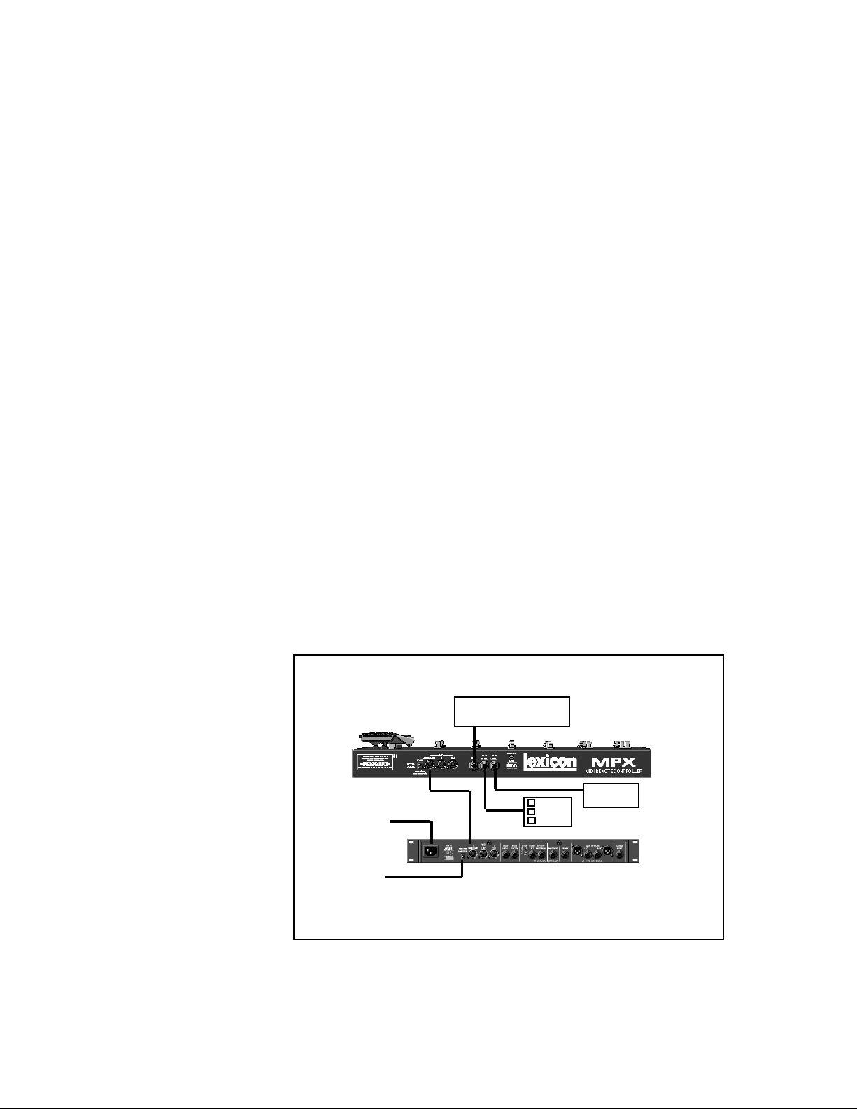
Connecting to an MPX R1
When an MPX R1 is connected to an MPX G2, two-way communication is
accomplished via MIDI System Exclusive messages. This allows immediate
response by both units to actions on either front panel.
Connect the power adapter provided with the MPX R1 to the MPX G2 REMOTE
POWER input jack and to a wall outlet.
Power up the MPX G2 and connect the 7-pin DIN cable provided with the
MPX R1 between the MPX G2 rear panel IN/REMOTE jack and the MPX R1
MIDI OUT/REMOTE.
1-8
The MPX R1 will cycle through a power-up routine, lighting various LEDs, and
then display Con. The MPX G2 will display Remote Detected. These messages
indicate that proper bidirectional control has been established.
Relay
(Amp Channel Select)
7-pin DIN
to AC Power
Source
to Lexicon
MSA Adapter
Connect a 7-pin DIN cable between the MPX (1 or G2) and the MPX R1.
Connect the MPX (1 or G2) to the MSA adapter provided with the MPX R1.
Cable
Foot
Switch
Foot Pedal
Page 22
Reverb
Chamber
Hall
Plate
Ambience
Gate
1-Band (M)
2-Band (M)
3-Band (M)
4-Band (M)
1-Band (S)
2-Band (S)
1-Band (D)
2-Band (D)
EQ
Fc Splitter
Crossover
Volume (M)
Volume (S)
Volume (D)
PedalVol
ExtPedalVol
Panner
Auto Pan
Tremolo (M)
Tremolo (S)
UniVybe
CustomVybe
Phaser
OrangePhase
RedComp
Effect 2
BlueComp
DigiDrive1
DigiDrive2
OctaBuzz
SweepFilter
1-Band (M)
Wah 1
Wah 2
Pedal Wah1
Product Overview
Pedal Wah2
Volume (M)
Volume (S)
Volume (D)
PedalVol
ExtPedalVol
Test Tone
Click
Gain
Tone
Crunch
Screamer
Overdrive
Distortion
Preamp
SplitPreamp
Chorus
Chorus
Detune (M)
Flanger (M)
Flanger24 (M)
Flanger (S)
Rotary Cab
Aerosol
Orbits
Centrifuge1
Centrifuge2
Comb 1
Comb 2
Volume (M)
Volume (S)
Volume (D)
PedalVol
Delay
Delay (M)
Delay (S)
Delay (D)
Echo (M)
Echo (S)
Echo (D)
Looper
JamMan
Ducker
Effect 1
Detune (M)
Detune (S)
Detune (D)
Shift (M)
Shift (S)
Shift (D)
DiatonicHmy
Panner
Auto Pan
Tremolo (M)
Tremolo (S)
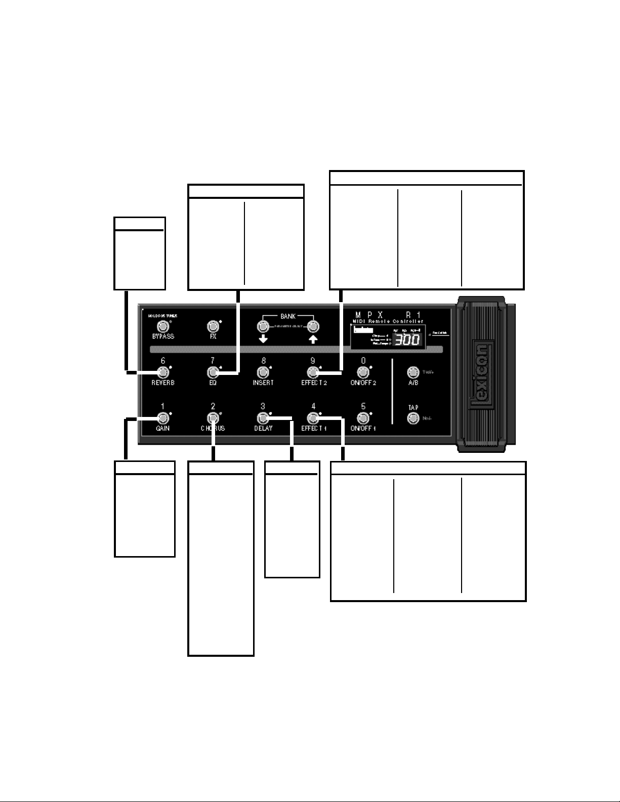
Connecting an MPX R1 to the MPX G2 gives you
stomp-box control of all of the MPX G2 effects.
UniVybe
CustomVybe
Phaser
OrangePhase
RedComp
BlueComp
DigiDrive1
DigiDrive2
OctaBuzz
SweepFilter
1-Band (M)
Wah 1
Wah 2
Pedal Wah1
Pedal Wah2
Volume (M)
Volume (S)
Volume (D)
PedalVol
ExtPedalVol
Test Tone
Click
1-9
Page 23
LexiconMPX G2 User Guide
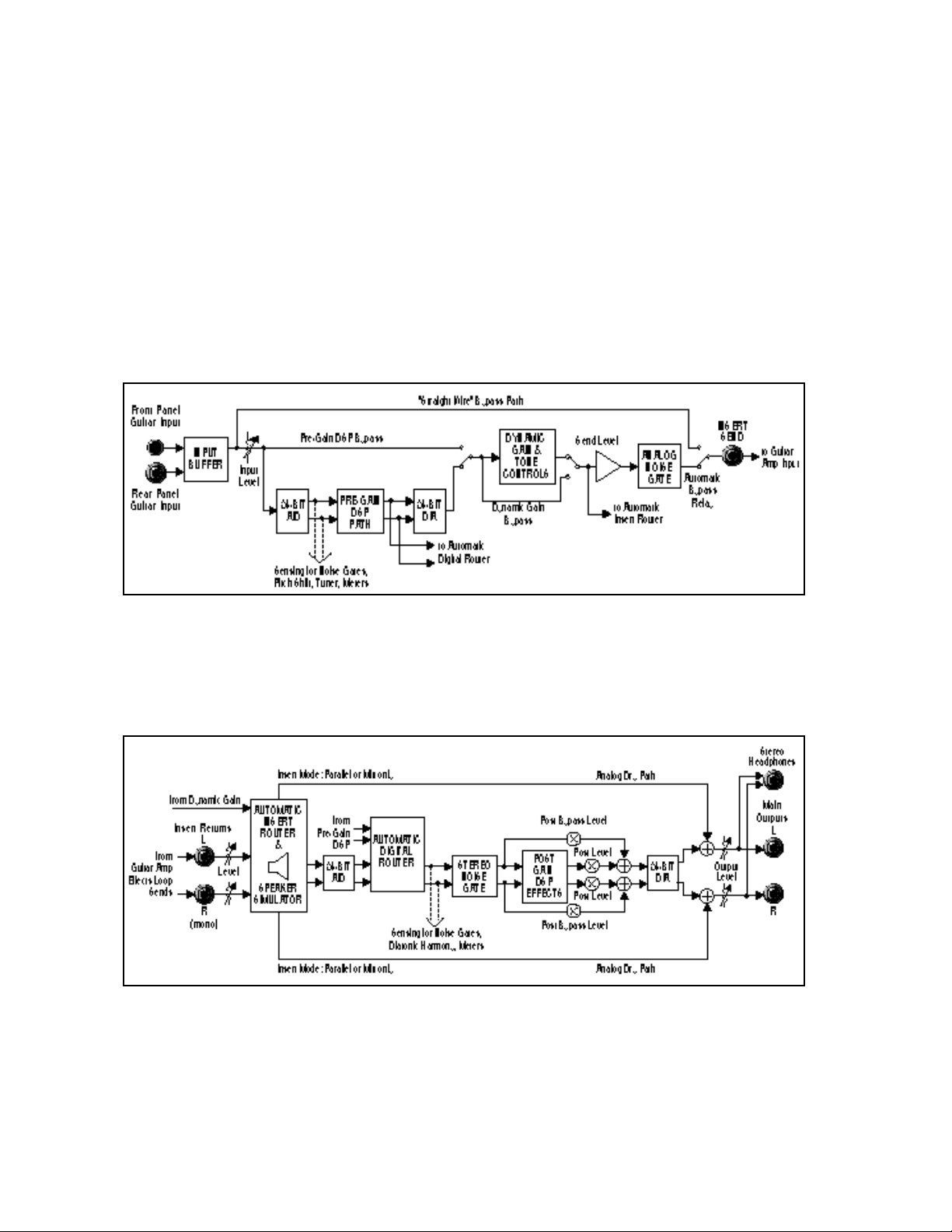
Signal Flow
Pre-Gain Path
Following are diagrams showing signal flow in the MPX G2 Pre-Gain and PostGain paths. When combined, these two diagrams show the entire signal path
between your guitar and the Main Outputs when the MPX G2 is used as a
standalone processor. Depending on which effects are active in a given
program (and where they are placed), the MPX G2 will automatically route
around unnecessary analog circuits as well as A/D and D/A converters. This
allows signal-to-noise and dynamic range to be optimized for every program.
Effect 1, Effect 2, Chorus, Delay, Reverb and EQ can be placed in any
combination on either, or both, pre gain and post gain paths.
This is the signal flow between your guitar and amp when Insert Send is
connected to the input of the guitar amp (pre gain path). The “straight-wire”
bypass path and automatic bypass relay function as an effect loop switcher. The
analog noise gate will help keep noise under control when you use effects in front
of your amp’s high-gain channel.
1-10
Post-Gain Path
This is the effects loop processing path when the Insert Returns are connected
to your amp’s effects loop sends (post gain path). The built-in Insert Router and
Digital Router automatically configure the signal flow based on which connections and settings you’re using. The stereo noise gate can reduce stage levels
to near silence when you stop playing - without muting the tails of post gain
effects like delays or reverbs.
Page 24

Product Overview
The MPX G2 is a complete guitar processing system. As such it has two
independent audio paths: one for effects that go directly between the guitar and
the input to the amp (pre-gain path), the other for effects that are inserted in the
amp’s effects loop (post-gain path). Analog Dynamic Gain effects (Tone,
Crunch, Screamer, Distortion, and Preamp) are dedicated to the pre-gain path.
The other 70 effects can be placed anywhere on either path and each one of
the 300 MPX G2 programs can have its own unique combination of effects,
distributed on either path.
When different pieces of audio gear are connected together, care must be taken
to avoid ground loops (which can cause noise and hum problems). The MPX G2
uses a special grounding scheme to safely minimize grounding-related problems. All circuits are internally connected to a common ground plane. (This is the
same approach used to ground racks of gear in studio installations and touring
rigs.) The chassis is isolated from the printed circuit board to prevent ground
loops through the ground pin of the AC cord. No special cables are required
when connecting the MPX G2 to other equipment.
Note that the G2 must always be properly grounded via the ground pin in its AC
line cord.
With the exception of the Main Outputs and the stereo Headphone connectors,
all of the 1/4" connectors are unbalanced mono jacks. For best performance use
high-quality, shielded instrument cables.
Dual Audio Paths
Internal Grounding
Unbalanced
Connections
The MPX G2 has two high impedance guitar inputs: one on the front panel and
another on the rear panel. Connecting to the front panel input will override a
connection made at the rear panel input.
For best performance, maintain balanced connections, and use high-quality,
low-capacitance, shielded twisted-pair cable. Use shielded instrument cables
for unbalanced connections.
When connecting the MPX G2 XLR outputs to single-ended, unbalanced
devices, leave the low side floating and connect the grounds between the
units.
Guitar Input
Main Outputs
1-11
Page 25

LexiconMPX G2 User Guide
Insert Send
Insert Returns
The MPX G2 Insert Send is always active. When Gain is on, its signal is from the
Gain block output. When Gain is bypassed, or when no Gain effect is in the
program, its signal is from the Gain block input. Note that this signal passes
through a programmable level control (Edit mode: Mix: Send Level) and analog
noise gate before leaving the unit via the Insert Send jack. Note also that
whenever there are no active effects between the guitar input and the Insert
Send, a relay automatically switches in a “straight-wire” bypass path. This
ensures that there is nothing between your guitar and your amp unless one or
more pre-gain effects are active. (Until the MPX G2, the only way to get this same
kind of analog purity when using effects was to install a dedicated effects loop
switching unit.)
Inserting a jack into either (or both) Insert Return connectors breaks the
normalled connections between pre-gain and post-gain paths, allowing you to
insert an external device (guitar preamp, effects processor, etc.) into the MPX
G2 signal path. When an external device is inserted, the front panel Insert button
LED will light.
The external device can be bypassed by pressing Insert (its LED will go out).
When the MPX G2 is connected to an amp’s effects loop, you can use the Insert
button to bypass the amp’s preamp and send MPX G2 signals directly into the
amp’s power amp. This feature allows you, for example, to switch between your
amp’s high-gain channel and an MPX G2 Gain effect clean channel.
1-12
Automatic
Insert Return
Signal Routing
Right (Mono) Only
Stereo
Left Only
The Insert Return jacks have software-controlled sensing and switching circuitry
to automatically route signals depending on which jacks are used and the MPX
G2 bypass state.
When only the Right Insert Return is connected, its signal is split and sent into
both the left and right channels of the post-gain path. When the unit is bypassed,
the dry Insert signal will be present at both outputs.
When both Left and Right Insert Returns are connected, their signals are sent
in stereo to the left and right channels of the post-gain path. When the unit is
bypassed, the dry stereo signal is present at the outputs.
When only the Left Insert Return is connected, its signal is sent only to the left
channel of the post-gain path. The right channel of the post gain path is
“normalled” to the right channel of the pre gain path. When the unit is bypassed,
the dry Insert signal is present on the left output and the Guitar Input signal is
present on the right output.
Page 26

Product Overview
The MPX G2 Main Outputs are set to stereo at the factory. When connecting the
MPX G2 to an external device with a mono input (such as a mono effects loop
return), set the Main Outputs for mono as follows:
1.Press System twice. The display will show System select: Audio.
2.Press > to select Audio OutputMode.
3.Turn the knob to change the setting from Stereo to Mono.
4.Press Program to return to Program mode.
The MPX G2 is factory set to produce unity gain when the front panel Input and
Output controls are set to 2 o’clock, and the Input Clip and Aux In Clip LEDs only
come on briefly during your very loudest playing (if at all). (See Quick Start earlier
in this chapter for detailed instructions on setting levels.)
Soft Sat is a built-in analog limiter that precedes the A/D converters in the MPX
G2. If the source to the MPX G2 is "hot", you can use Soft Sat to reduce the
harshness caused by overloading the A/D converters. Press System, select the
Audio menu, then select Soft Sat to turn the limiter On or Off.
The green Level LED indicates signal presence (above -30dB) at either the front
or rear panel guitar inputs. The red Clip LED indicates overload at either of these
inputs, or overload of any effect in the pre-gain path.
Connecting
the Main Outputs
to Mono Input
Setting Audio Levels
Using Soft Sat
Input Level and Clip
Indicators
The Aux In LED indicates signal presence at either of the two Insert Return
jacks. The Aux In — Clip LED indicates overload of either of the Insert Returns,
or overload of any effect in the post-gain path.
Aux In and Clip
Indicators
1-13
Page 27

LexiconMPX G2 User Guide
1-14
Page 28
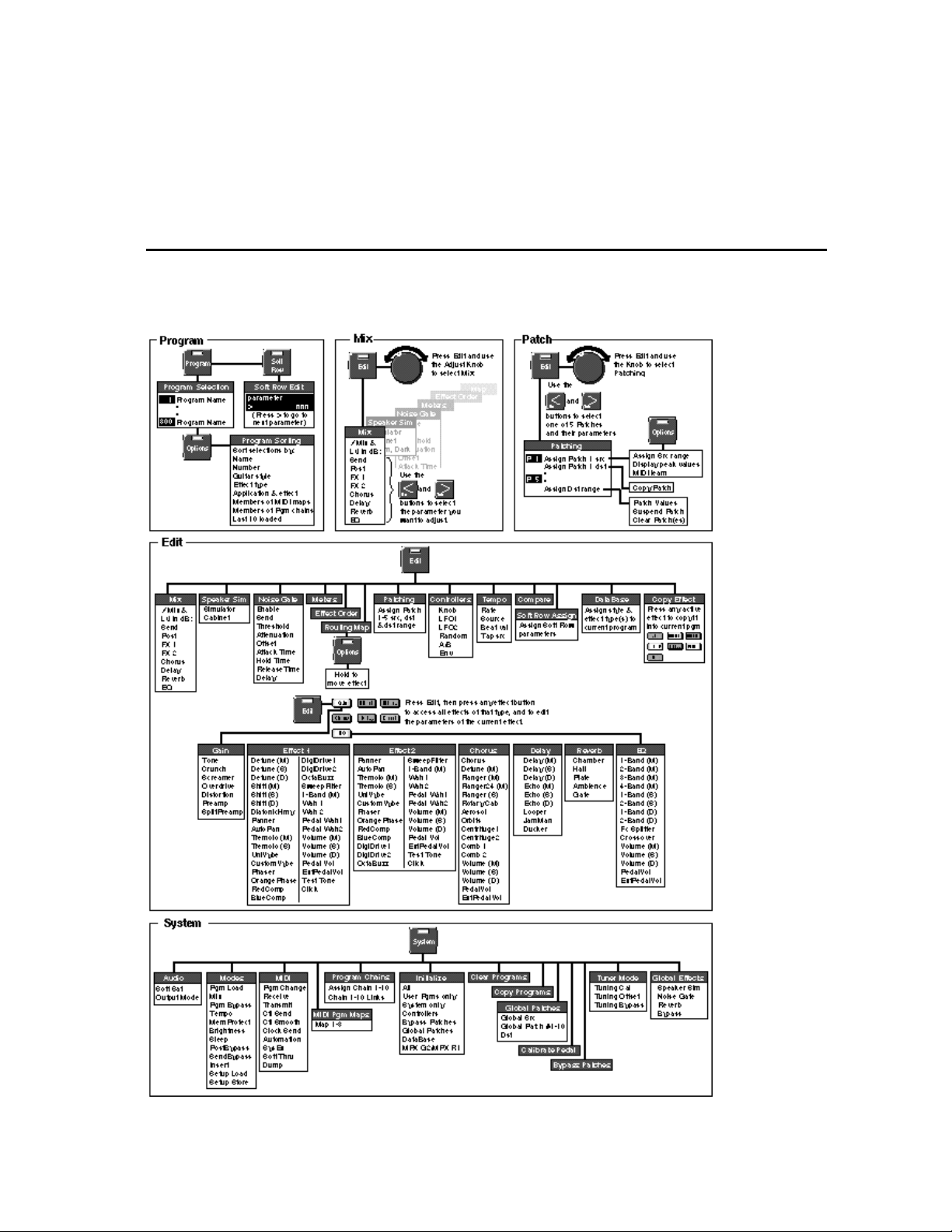
Basic Operation
2
Beginning with a menu tree to guide you through the major areas of the MPX G2,
this chapter focuses on the basics that you want to get to first — finding, loading,
tweaking and storing programs.
Basic Operation
MPX G2 Menus
2-1
Page 29
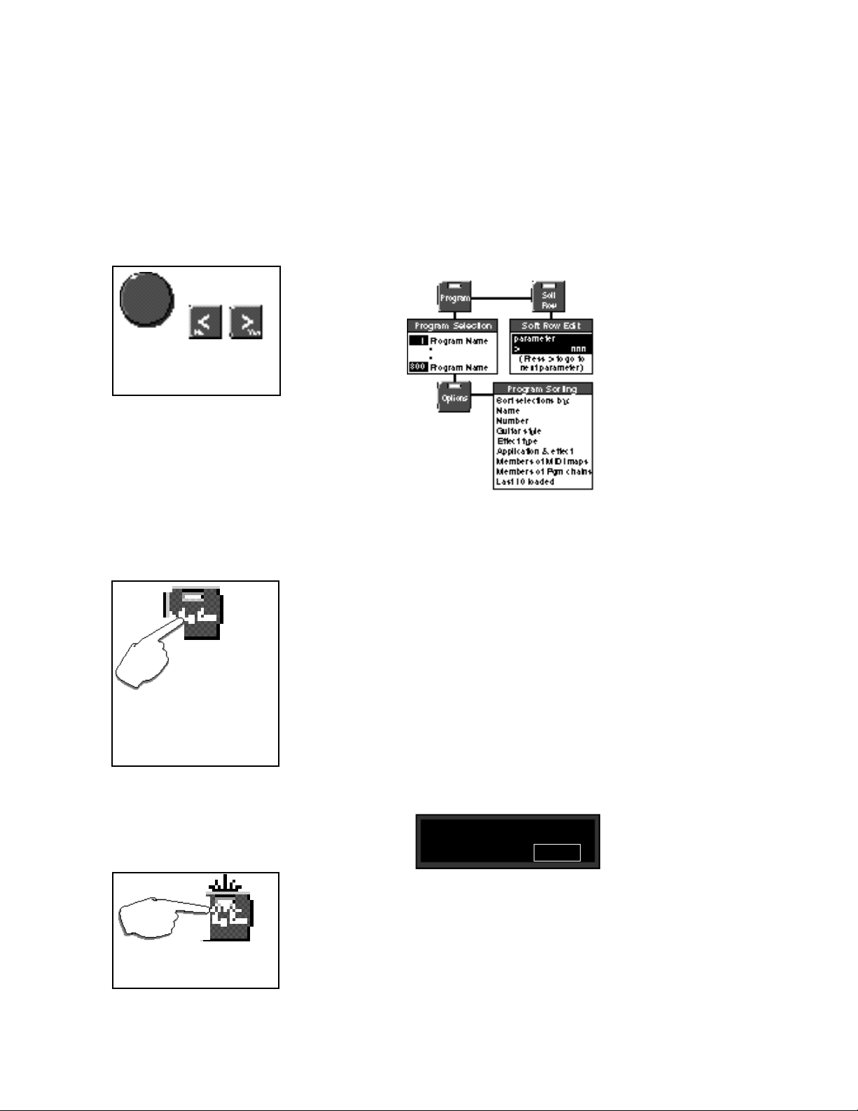
LexiconMPX G2 User Guide
Loading and Playing
with Programs
When loading programs, the knob
selects programs. The < and >
buttons jump to the next DataBase
sorting category.
Program Load
Pressing the front panel Program button accesses the MPX G2 library of 300
presets and user programs. In this mode, you can select and load programs,
select database sorting criteria and access the "Soft Row" — a selected set of
the most useful parameters for each program. You can also access Tap, A/B,
Mix and Patch functions, as well as selecting and bypassing effects in the
program. Each of these is described in this section.
When you press the Program button, its LED will light to let you know you're in
Program mode.
Press and hold the Pro-
gram button to display
the name and number of
the currently running program
while another program is displayed.
If the displayed program is currently
loaded, pressing and holding Pro-
gram will display the effect routing
assignment.
In Manual Load, press the flashing Program button to load the
displayed program.
Auto Load
When first shipped, the MPX G2 will default to automatic program load, with all
of the programs available in numerical order from 1 to 300. The top line of the
display will show the DataBase sorting option "Sorted by number". The bottom
line of the display will show a program name. The large numeric display will show
the ID number of the displayed program.
Turn the knob to display and load other programs. An asterisk (✱) will appear
briefly before each program name before it loads.
Manual Load
To switch to manual program load, press System. Use the knob to select
Modes, then use the < and > buttons to display:
Modes: Pgm Load
< > Auto
Turn the knob to select Manual. In this mode, an asterisk (✱) before the program
name indicates that the displayed program is not loaded, and the flashing
Program button LED indicates that the program is cued for loading when
Program is pressed. (When the currently loaded program is selected, the
Program button LED will light steadily, and there will be no asterisk in the
display.)
2-2
Page 30
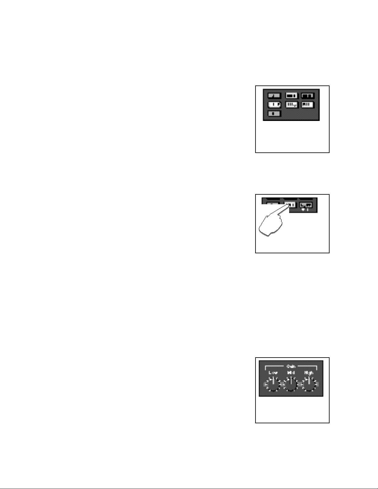
Basic Operation
The front panel Effect buttons light to show you which effect blocks are active.
— When you're scrolling through programs, they'll change to show you the
effects in any displayed program. Once you stop scrolling, they'll return to
display of the effects that are active in the currently loaded program.
To bypass any active effect, press its button. The light will turn off and the effect
will be bypassed. Press the button again to make the effect active again.
Press and hold down any effect button to display the name of the effect and
information about its status in the program (on or off).
External audio gear (guitar preamp, CD player, etc) can be inserted into the
MPX G2 audio path via the rear panel Insert Return jacks. The front panel Insert
button will light to show you when this connection is active.
To bypass this external connection, press Insert. The LED will turn off and the
inserted gear will be bypassed. Press Insert again to make the inserted gear
active again.
When the MPX G2 leaves the factory, Insert connections are routed in series
between the pre-gain and post-gain paths. (This is the best routing to use when
connecting to amplifier effects loops.) You can alter this routing by changing the
setting of the Insert parameter in the System: Modes menu. Be sure to read
about the three different Insert Modes (FX Loop, Mix and Parallel) in Chapter 5:
System Controls.
Effect Bypass
The active effects of the currently
loaded program are lighted. Press
any lighted button to turn the effect
off. Press it again to make the effect
active again.
Insert Bypass
Press the lighted
Insert button to
bypass devices
connected at the MPX G2 Insert
Return jacks.
NOTE: When the MPX G2 is connected to a guitar amp with an effects loop, the
Insert button allows you to switch the guitar amp’s preamp in and out of the audio
path. When it is out of the path, the guitar signal flows through the pre- and postgain paths and then directly into the power amp. This allows you to switch
between dramatically different tones with a single button push.
The MPX G2 has three dedicated front panel tone controls which allow instant
modification of the Low, Mid and High settings of the Dynamic Gain effect in the
current program. These controls are analog pots. Changes made with these
knobs take place immediately (You don’t have to pass-through the current
value- once you move the knob, it “owns” the parameter.)
When any of these controls is moved, the display will briefly show the current
values of all three controls, then return to the previous screen. Changed settings
can be stored by pressing Store to initiate the Store procedure.
Be aware that in many of the Dynamic Gain effects, these tone controls interact
with the analog distortion circuitry, increasing or decreasing the amount of
distortion in Low, Mid and High frequency bands.
Dedicated Analog
Tone Controls
Dedicated front panel tone controls allow instant modification of
the Dynamic Gain effect in the
current program.
2-3
Page 31

LexiconMPX G2 User Guide
Programmable
Bypass Modes
You can choose to have Bypass
bypass the pre-gain path, the postgain path, or both paths in System
mode.
Tuner
As the MPX G2 is designed with separate pre-gain and post-gain effects paths,
the master Bypass button can be progammed to function in a variety of useful
ways. The factory setting is for both paths to be bypassed when Bypass is
activated. You can choose, however, to have this button bypass only the pregain path, only the post-gain path or both paths.
Bypass behavior for each path can be independently programmed as well. The
pre-gain path can be set to Disabled or to provide an analog "straight wire"
Bypass.
The post-gain path can be set to Input Mute (delays and reverbs will "ring out"
when bypassed), All Mute (no output when bypassed) or Bypass. When set to
Bypass, the post-gain path has an optional Bypass Level parameter that
allows you to set an independent level for when the post-gain path is bypassed.
(Be sure to read about SendBypass and PostBypass under System: Modes in
Chapter 5: System Controls.)
The MPX G2 has a built-in chromatic tuner. To activate the tuner, press and hold
Bypass. When the tuning displays appear, release the button and play a note.
The displays will show the name of the note you played, and also indicate how
flat or sharp it is.
+ - - - - - [ ❚ ❚ ] - - - - - +
note= E
When the MPX G2 is connected to
an MPX R1 MIDI Remote Controller, the tuner is also displayed on the
MPX R1 numeric display.
Flashing of the Tempo LED indicates that Tap is active. Press Tap
twice in rhythm to change the tempo
of delay or modulation parameters
in the current program.
2-4
The note you play is shown on the display along
with indicators to show whether the note is sharp,
flat, or in tune.
When you’re finished tuning, press Bypass again to return to normal operation.
When the Tuner is activated, the Insert Send and Main Outputs are automati-
cally muted. You can change this behavior by changing the setting of the Tuning
Bypass parameter in the System: Tuner Mode menu. (See Chapter 5: System
Controls.)
Tap
MPX G2 tempo controls are available right on the front panel through the Tempo
LED and the Tap button. Many preset programs are designed with their own
tempo rate settings which are stored with the programs. The front panel Tempo
LED will flash in tempo whenever you load a program with tempo control. This
flashing indicates that the Tap button is active, allowing you to change tempo on
the fly. Whenever you see the Tempo light flashing, simply press Tap twice in
rhythm to establish the rate you want.
You can override these individual tempo rates with a global tempo rate in the
System Setup menu. Tempo is also available as an independent patch source
which can control any effect parameter. (See Chapter 4: Patching and Chapter
5: System Controls.)
Page 32

Basic Operation
A/B is a unique glide function which allows you to "morph" between selected
parameters. Most effect parameters (or groups of parameters) can be patched
to the A/B controller. Once a parameter is patched, the A/B controls in Edit mode
allow you to select the rate at which you want to glide from A to B and from B to
A when the front panel A/B button is pressed. You can also assign the glide
function to be triggered by any internal source, such as input level, or by an
internal or external controller.
Many of the presets are designed with A/B patches that allow you to morph
between two effects, glide from slow to fast rotary speakers, start and stop loop
delays, etc. Loading any program with A/B control assigned, will cause the front
panel A LED to light, indicating that the A/B function is active. Press A/B to
activate a glide from the parameter values assigned to A to the parameter values
assigned to B. Press A/B again to glide back to the A parameter values. (When
you want to change the A/B parameters, control A/B remotely, assign a trigger
source, or alter the rate of glide, refer to Chapter 4: Patching and Chapter 8:
MPX G2 Internal Controllers.)
The MPX G2 offers access to the most useful parameters of any program without
having to enter a separate Edit mode. These parameters are available at any
time by pressing Soft Row.
The upper line of the display will show the Effect type, the parameter name and
the current parameter value. The lower line of the display will show the name of
the program. Use the knob to change the parameter value. Use the < and >
buttons to move back and forth between the available parameters. A scroll
indicator in the lower left corner of the display tells you whether or not there are
more parameters in either direction.
A/B
When A is lit, pressing the A/B button activates a parameter glide.
Pressing A/B again reverses the
glide.
Soft Row Editing
Press Soft Row to
access a set of the most
useful parameters for each program.
Changes you make to parameters in the Soft Row will be saved only until you
load another program unless you store your modified version of the program.
See Program Store later in this section.
Press Soft Row to access Soft Row parameters.
The Effect type and the parameter name will
appear on the upper line.
Gain Drive
> 25
Scroll indicators (< and >) on the bottom of
the screen point you in the direction of
additional screens.
The parameter value will flash in the lower
right. Use the knob to change the parameter value, use < and > to select another
parameter screen.
2-5
Page 33

LexiconMPX G2 User Guide
Using the DataBase
In Program mode ...
... press Options to access the
DataBase sorting options.
The MPX G2 has a database sorting function which allows you to sort and search
for programs in various categories. This is a great timesaver when you're looking
specifically for guitar effects, or EQ effects, or for EQ effects for guitar. When
shipped, the DataBase sorting option is set to "Sort by number", allowing you to
use the knob to scroll through all of the 300 programs in numerical order in
Program mode. (The < and > buttons will jump you forward and back ten
programs at a time. Simultaneously pressing < and > jumps from 1 to 251 or from
251 to 1.)
You can select other sorting criteria in Program mode by pressing Options. The
Options LED will blink and the display will show:
Sort programs
by number
Use the knob or the < and > buttons to select any of the main sorting options listed
below:
name
number
guitar style
(Acoustic, Bass, Blues, Clean, Country, Jazz, Rock)
effect type
(Chorus, Delay, Distortion, EQ, Flanger, Gain, Mod,
Overdrive, Phaser, Pitch, Reverb, SpkrSim, Wah, All)
application type
(StndAlne, Amp In, FX Loop)
members of MIDI maps
members of pgm chains
last 10 programs loaded
2-6
Press Options again to return to Program mode with the database sorted to
show only those programs that fit the criteria you've selected. If you select
"name", the knob will scroll you through all 250 programs in alphabetical order
(The < and > buttons will jump you forward and back through letters of the
alphabet.)
If you select any sorting option other than sort by name or number, the displayed
selection of programs will be limited to those which fit the category. — We've
made sure that all 250 of the factory programs are tagged for a variety of
appropriate sorting options, so you'll find plenty to play with in each category.
NOTE: MPX G2 programs have been designed for specific applications.
Stand alone programs may not sound right if listened to through a guitar
amp and vice versa.
When you select guitar style, effect type or app type as an option and return to
Program mode, the knob will scroll through the programs in the first of the
categories listed in parenthesis above. The < and > buttons will jump to the next
sorting category.
Assigning guitar style, effect and app types to programs is done in a database
menu in Edit Mode.
Page 34

Basic Operation
Once you've made changes to a program, such as turning an effect off, or
modifying any of the soft row parameters, an edit indicator in the display (•) will
appear in front of the program name. This identifies the program as having been
altered since the last store procedure. This edit indicator, along with all of your
changes, will disappear when you load another program.
To save your changes, press Store. The LED in the Store button will flash to let
you know you are in the middle of a store procedure and the display will show:
Program Name
251 available
The upper line of the display shows the name of the currently running program.
The lower line shows a user program number (251-300) and the name of the
program currently stored there. (When the MPX G2 is shipped, the user
programs are all "available".)
The < and > buttons move an underbar cursor in the display from the program
number to each letter of the current name. Turning the knob will select another
program number, or will select alphanumeric characters when the cursor is in the
upper line of the display.
Once you've made changes to the program name or selected a new location for
it, press Store again. The display will show:
Program Store
Press Store to
initiate the store
procedure.
The Store LED will
flash while you
change the name of
the program and decide where to store it.
Press the flashing Store button
to verify your changes.
Are you sure?
Yes or No
The numeric display will flash the user program number you have selected while
you decide to press > Yes or < No. Once you have stored your program, it will
automatically be added to the database and you will return to Program Load
mode.
The following are stored with the program*:
• All effects and their settings
• Effect Order and Routing Map
• Bypass state of each effect
• Insert state (if jack(s) are plugged into Insert Return(s) when the program is
stored)
• Master Bypass state of the program when it was stored
• Toe Switch setting (Option)
• Speaker Sim On/Off and Cabinet
• Noise Gate settings
• Tempo settings
* This assumes that Reverb, Speaker Sim, Noise Gate, Tempo and/or Bypass modes are set to
Program. Any of these that are set to Global, will not be stored.
NOTE: If the stored program no longer meets the DataBase sorting criteria of the
original version, the MPX G2 will automatically switch the DataBase setting to
"Sort by number".
Press Yes to complete the store.
2-7
Page 35

LexiconMPX G2 User Guide
2-8
Page 36

Editing
3
This chapter describes all of the MPX G2 edit functions. As the first thing you are
likely to want to modify in a program are its effects, this section starts there and
then moves on to all of the functions available in Edit mode.
To edit any effect, press Edit, then press an Effect button to view all of the Effects
of that type, and to edit the parameters of the current Effect. The display will show
the Effect type and the name of the currently loaded Effect . Turn the knob to view
other Effects of the displayed type.
Editing
Effect Editing
This indicator shows that
Options are available
FX 1■select: nn
Arrow scroll
The Effect name will be marked with an asterisk (✱) and the Effect button light
will blink rapidly if the displayed effect can be loaded in the current program.
(Press and hold the Effect button to display the name of the Effect currently in
use.)
An X appears in place of the asterisk if there are not enough DSP resources to
load the effect. Two seconds after an algorithm is selected with the knob, the
following screen will appear briefly, showing the number of resources available:
Number of processing
steps used (including the
currently running effect)
> ✱ Effect Name
number of processing
steps remaining
nn available
XXX of 190 used
Knob scroll
▲
▼
Number of processing
steps used for this effect
3-1
Page 37

LexiconMPX G2 User Guide
Coarse and Fine Editing
of ms and Hz values
Parameters whose values are displayed in ms or Hz have overall
ranges of more than 1000 units.
When you select one of these parameters for editing, you’ll notice
that either the left or right portions of
the value can be selected for editing.
For quick, coarse adjustments, select the left portion of the value. For
fine adjustments, select the right
portion of the value. The fine and
coarse increments for each type of
parameter are:
ms (delay times)
coarse increments=100 ms
fine increments=1ms
Hz (LFO rates)
coarse increments=1 Hz
fine increments=.01Hz
Hz (EQ Fc)
coarse increments=100 Hz
fine increments=1Hz
If there are not enough resources available to load the effect you want, another
effect must be removed from the program to make resources available.
To load any available Effect, press the Effect button again. The asterisk will
disappear from the displayed name and the button light will return to its normal
slow blinking edit state. An edit indicator is displayed to indicate that the active
program has been modified.
To edit the parameters of the current effect, press > . The display will show one
or more parameters as shown below.
An edit indicator appears in front of the
parameter name if the value has been
changed since the last store operation.
A patch indicator appears before the parameter name if it is
controlled by a patch.
The Effect type is
shown in the upper
left of the display.
Effects with Rate and Depth, or
other dynamic parameters,
have animated meters here.
FX 1P.Mix Level
< > ❚ 100% 0 dB
One or two parameters will be
shown on each parameter screen.
Parameter values
are shown on the
bottom line of the
display.
Fields which are selected
for changing will blink.
The item on the lower line of the display which is selected for adjustment will
flash. Turn the knob to scroll through the entire range of parameter values. Use
the < and > buttons to select another parameter value field and to move to
another parameter screen.
Press Options to set the
MPX R1 Toe Switch to
control Bypass
of the effect, or
to disable the
Toe Switch.
3-2
Detailed information on each Effect and its parameters is provided in Chapter 7.
Press Edit to return to the main Edit menu.
Effect Select Option: Toe Switch (when an MPX R1 is connected)
When an MPX R1 MIDI Remote Controller is connected to the MPX G2, the Toe
Switch option allows you to use the R1 Toe Switch to turn the effect you are
editing on, to bypass it, or to specify that the Toe Switch have no effect.
This powerful feature allows you to group different effects to be turned on or off
whenever the MPX R1 Toe Switch is pressed. For example, set Wah for
Off=Bypass and set Chorus for On=Bypass to switch between a Wah and
Chorus whever the Toe Switch is pressed.
To assign a Toe Switch function to an effect you are editing, press Options from
the FX select: display. Use the knob to select On = Bypass, Off = Bypass or
disabled. Once you have made your selection, press Options again to return
to Effect Edit mode.
Page 38

Editing
The MPX G2 Edit menus give you access to all of the controls you need to create
your own programs. Whether you want to view the meter display, re-route the
effects in a program, or create an entirely new sound, you will find the tools you
need in this section.
The complete Edit mode menu structure is shown below, followed by detailed
explanations of each main menu selection.
Press Edit to enter the main Edit menu. Use the knob to select the particular
submenu you want (Mix, Speaker Sim, etc.).
The MPX G2 Edit
Menus
Edit select:
▼
> Mix
Use the < and > buttons to enter the submenu and select parameters, and the
knob to adjust parameter values. Press Edit again to return to the main Edit
menu.
Each of the Edit submenus is discussed in the following pages, in the order they
appear in the Edit menu.
3-3
Page 39

Press Edit to enter the main Edit menu and use the knob to select Mix.
Mix
The display will show Mix and Level labels on the upper line, and the current
settings on the lower line. One of the values on the lower line will be flashing to
let you know which is selected for adjustment. Use the < and > buttons to select
Send Level, Post Mix and Level, or to step to the Mix and Level controls for any
active effect in the currently running program. Use the knob to adjust the flashing
parameter value.
Use > to step to the Level parameter, or to step forward
to the next screen of Mix and Level parameters.
Post Mix Level
< > 100% 0dB
The knob will adjust the flashing parameter value.
LexiconMPX G2 User Guide
Adjusting Pre-Gain and
Post-Gain Level
With the Send or Post
parameter displayed,
press Options to
access Bypass
Level.
In the MPX G2, both the pre-gain and post-gain paths have independent
programmable level controls. Be sure to read about MPX G2 signal flow in
Chapter 1.
The Send parameter controls the level of the Pre-Gain signal leaving through the
rear panel Send jack. When the front panel Input knob is set correctly (with the
Clip LED lighting only occasionally during your loudest playing), a Send Level
of 0dB will match the level of the Unity Gain Relay Bypass.
The main purpose of this control is to allow you to match the overall Pre-Gain
effects level with the level when the Pre-Gain path is bypassed. It can also be
used to provide clean boost to add additional punch to kick a clean amp into
overdrive.
Send Options: Send Byp Level
This parameter controls the Send output level during the transition between two
programs when a new program is loaded — to allow you to smooth out any
volume differences that might occur during program load. For most programs
this level should be set to 0dB.
The Post-Gain path also has programmable effects and bypass levels. The Post
Level parameter sets the overall level of wet (effects only) signal. It can add as
much as 6dB of additional gain.
Post Options: Post Byp Level
This parameter sets the output level of the Post Gain path when it is bypassed.
A setting of 0dB corresponds to unity gain.
3-4
These parameters allow you to match Post-Gain effects and bypass levels so
that transitions between bypass states and program loads will be smooth. For
most programs the Post Byp Level should be set to 0dB and the Post Level
parameter should be changed to match the bypass level.
Page 40

Editing
The MPX G2 has a progammable analog speaker simulator which is located
between the pre- and post-gain paths. When used as a stand alone processor,
the speaker simulator is connected to the output of the MPX G2 analog preamp.
The speaker simulator can be set to Global or Program mode. When set to
Global, the current speaker simulator settings will be active for all programs
when they load. (This is a quick way to turn the speaker sim on or off for all
programs.) When set to Program, each program will load with its own Speaker
Sim settings.
When the speaker simulator is active, a small speaker icon appears in the
Program display.
Be aware that the factory programs that use the speaker simulator were
designed to sound best when the MPX G2 is used as a stand alone processor.
These will sound overly dark if used through a guitar amp and speaker cabinet.
(Just turn Speaker Sim off if you want listen to them through a guitar amp.)
Likewise, factory programs that don’t use the speaker simulator will sound best
through a guitar amp. Programs that use a gain effect and don’t use the speaker
simulator will sound harsh when you listen to them directly through headphones
or at a console. (Turn Speaker Sim on to listen to these programs direct.)
There are 4 cabinet designs to choose from: Combo1, Combo2, Stack 1 and
Stack 2.
Combo 1 is an open-back cabinet with 10” speakers.
Combo 2 is an open back cabinet with 12” speakers.
Stack 1 is closed back with 12” speakers.
Stack 2 is closed back with 10” speakers.
Speaker Sim
NOTE: You can use the simulator
to process the output of an external
preamp by simply connecting the
external preamp to the MPX G2
Return jack(s). The speaker simulator is a mono circuit. When both
returns are used, they are summed
to mono within the speaker simulator.
See diagrams on the following
page.
Each cabinet can loaded with one of four speaker types: Bright, Normal, Warm,
and Dark.
3-5
Page 41

Automatic
Speaker Sim Routing
All routing to and from the Speaker
Simulator is automatic, based on which
Insert Return jacks are used and
whether or not Split Preamp is loaded
into the Gain effect block.
LexiconMPX G2 User Guide
3-6
Page 42

Editing
The MPX G2 has two integrated noise gates, one analog and one digital. Both
are driven by the direct signal. The gates share a common set of parameters and
can be used independently, or combined to create a “super gate”.
The analog gate is the final output stage of the MPX G2 pre-gain Insert Send
path. This allows you to gate the analog signal connected to your guitar amp. The
attack and release times of the analog gate are fixed (both are preset to be very
fast).
The digital gate is located on the post-gain path, immediately after the Insert
Returns. This stereo gate allows you to gate the effects Send signal coming from
an external guitar preamp before it is processed by any post-gain effects such
as reverb or delay. (This means that reverb and decay tails will ring out naturally
when the gate shuts down.) The digital gate is driven by the same pure guitar
signal as the analog gate, so both gates have the same sensitivity to light touch
— no matter how many effects the guitar is going through.
When the MPX G2 is connected in front of an amp and/or in the effects loop,
these two gates form an integrated noise reduction system that provides more
than 120dB of attenuation. When the G2 is used with amp input only, the analog
gate provides 40dB of attenuation. When the MPX G2 is used as a stand alone
processor, the digital gate provides 90dB of attenuation.
Signal Flow with no Returns connected
The Analog Noise Gate controls the
signal leaving the Send jack. It is
used to gate audio going to a guitar
amp input.
The Digital Noise Gate controls signals
going to the post-gain path. It is used to
gate audio from the pre-gain path (no Inserts connected) or to gate audio coming in
through the return jacks.
Signal Flow with Returns connected
Noise Gate
Given a choice, many players
prefer not use gates of any kind
as they can affect tone and playing style dynamics. In live and
recording situations where highpowered amps are pushed hard,
however, the use of a gate is
sometimes unavoidable. (If a
player uses stomp-box effects in
front of the amp, and rack effects
in the effects loop, two gates are
required: one between the amp
input and the last stomp box in
the effect chain, and another on
the amp's effects send to gate
noise before it hits the rack processors.)
In a component system, the gate
is driven by the processed guitar
audio — which means that the
threshold must be set quite high
to compensate for all of the noise
added by the pre-gain effects
(wah, compressor, overdrive,
etc.). You have to play pretty hard
to get the gate to open up, and
sustained notes are noticably
chopped off.
As the MPX G2’s analog gate is
driven by the unprocessed guitar, the threshold can be set
much lower, creating a sensitive
gate that opens up with a very
light touch and which remains
open considerably longer during
sustaining notes and chords. It
also makes it possible to use the
guitar’s volume control to control the gate directly.
Both the analog and digital noise gates
share the same sensing — which can
be set to either Guitar Input or Return
Only.
3-7
Page 43

LexiconMPX G2 User Guide
Meters
The G2 has a built-in meter array that allows you to simultaneously view guitar
input level, main output levels as well as the levels of all individual effects blocks,
except Gain.
The meters are displayed in fixed order: Input, Effect 1, Effect 2, Chorus, Delay,
Reverb, EQ, Output.
Effect blocks are indicated by their
number or inital letter.
I 1 2 C D R E O
+
❚ ❚ ❚ ❚ ❚ ❚ ❚ ❚
Each effect block has a 7-segment with an
overload indicator (A + at the top of the
meter block).
Each block’s output level is shown with a 7-segment meter. Overload is indicated
by displaying a plus sign on the top right side of the individual meter.
Use the meter display to check levels throughout the effect chain, or to track
down overload in an individual effect.
3-8
Page 44

Editing
Selecting Effect Order from the Edit menu allows you to put the seven MPX G2
Effect blocks in any order you wish. Press > to display the current ordering and
routing configuration. An ordering display such as the one shown below will
appear.
An underscore identifies the Effect block which
is selected for moving to a new location.
1=2=g=C=D=R=E
Effect types are represented by their initial letters or numbers.
Upper case letters and large numbers indicate that the Effect is
active in the current program. Lower case letters and small
numbers indicate that the Effect is inactive.
Each Effect block is represented by a single letter or number, an upper case
letter or large number if the Effect is active in the current program, a lower case
letter or small number if it is not. The symbols between each letter indicate the
current routing connection options. An underscore identifies the Effect block that
is currently selected for repositioning. (In the example shown above, the Chorus
block is selected.) To move the selected block to a new position, simply turn the
knob. Use the < and >buttons to select (underscore) a different Effect block for
repositioning.
Using the same example, turn the knob two clicks to the right to move the Chorus
block and alter the Effect Order as shown below.
Effect Order
The Chorus block is selected for
repositioning.
Turn the knob one click to the right to
swap the Chorus block with the Delay block.
Turn the knob one more click to the
right to move the Chorus block another step to the right.
1=2=g=C=D=R=E
1=2=g=D=C=R=E
1=2=g=D=R=C=E
Press Edit to return to the main Edit menu.
3-9
Page 45

LexiconMPX G2 User Guide
Routing Map
The MPX G2 allows you to reconfigure the effect blocks along audio paths of
your own design. The Routing Map is a graphic display that shows routing and
connections between the MPX G2 effect blocks. Use the Routing Map to change
connections between individual effects and also to change the overall routing
configuration of all seven effect blocks as a group. All of the routing controls
available in the Routing Map menu are explained in this section, along with
examples of the selections you can make. Remember that you can change the
order of the effect blocks as well. (See Effect Ordering on the previous page.)
In these examples, we'll use the default effect order to keep things simple.
Before going into the details of the Routing Map, it's worthwhile to review basic
signal flow through the MPX G2.
The overall signal flow through the MPX G2 is divided into two paths: a pre-gain
path and a post-gain path. The six DSP effect blocks (Effect 1, Effect 2, Chorus,
Delay, Reverb and EQ) can be placed in any combination on either the pre-gain
or post-gain portions of the audio path.
The position of the Gain effect block in the Routing Map determines the
boundary between the two paths. The pre-gain path is made up of the Gain effect
block and all effects on the path that connect to the inputs of the Gain effect. The
post-gain path consists of all effects on the path connected to the outputs of the
Gain effect block.
3-10
When you want to connect the G2 to external guitar amp or other gear, it is
important to understand where the Send and Insert Returns are in relation to the
Routing Map display. The Send jack is permanently connected to the path at a
point immediately following the Gain block outputs. The Insert Return jacks are
permanently connected to the path at a point immediately following the Send.
Page 46

The path through an MPX G2 DSP effect block looks like this:
Note that the dry path through the effect is stereo, and a variable wet/dry mix is
included for each DSP effect. The wet path through the effect can be stereo or
mono in, and stereo or mono out, depending on the particular effect.
The path through an MPX G2 analog Gain effect is slightly different:
Editing
Note that there is no wet/dry mix path for the analog effects and that these effects
are mono in and mono out.
Each of the Effect blocks (Effect1, Effect2, Gain, Chorus, Delay, Reverb and EQ)
is represented in the following discussion as a simple box identified by its first
initial (1, 2, G, C, D, R and E). This is also the way each block is represented in
the MPX G2 Routing Map display. MPX G2 inputs and outputs are represented
by the letters I and O.
Active Effects are represented (here and in the
Routing Map) by upper case letters and numbers.
Inactive Effects are represented (here and in the Routing
Map) by lower case letters and small numbers.
Insert Sends and Returns are not shown in the Routing Map, but they are always
located between the Gain block and any blocks that follow it.
3-11
Page 47

LexiconMPX G2 User Guide
How to Change Routing
Connections
How to Change Routing
Options
The routing page lets you alter the connections between the inputs of the
selected block and the outputs of the blocks in front of it. It is easy to think of these
connections as patch cords connecting the different blocks. There are five
possible connections for the inputs of any block.
On the Routing Map, use the < and > buttons to select any upper case letter.
(Lower case letters indicate inactive effects, which cannot be edited.) Use the
knob to set your connection choice.
The signal path within the MPX G2 can be split into two parallel stereo paths, and
once split, the split paths can be merged together again. The split paths are
referred to as Upper and Lower. The Routing Map options allow you to choose
where to split and merge the path and to place effect blocks on either the upper
or lower paths. The following examples show four general configurations: a path
with no split, a split pre-gain path, a split post-gain path, and a parallel path
around the pre and post paths.
Press Options to determine the
routing configurations for all
blocks. Press Options again to
return to the Routing Map.
3-12
All seven effects are on the upper
path.
The pre-gain path is split at the input
and merged at the Gain effect.
The post-gain path is split at the Chorus effect and merged at the EQ effect.
Splitting the path at the input and
merging it at the outputs creates a
separate path in parallel with the pregain and post-gain paths.
To change the routing, from the Routing Map, press Options. Use the < and >
buttons to select individual blocks. Use the knob to change the configuration.
Note that the MPX G2 will only display the routing options that are available in
the current configuration. For example, if all seven blocks are on the upper path,
the only available option will be Split. The next block downstream from a Split
will have Upper, Lower, and Merge available as options.
Page 48

Editing
In the following examples we’ve selected three presets that demonstrate
creative applications of the routing and connection capabilities of the MPX G2.
Example 1:
Program 198 Cordovox
Cordovox Routing Map
(Stand Alone)
Routing Examples
This program produces the sound of a vintage Cordovox rotary speaker. The
Cordovox is a speaker cabinet containing a fixed 8-inch speaker mounted
behind a rotating baffle. It projects sound out of the sides and top of the cabinet,
not the front. The baffle can rotate at either fast or slow speeds. The transition
time between the different rates is quite long. The characteristic swirling sound
it produces is the result of doppler and panning effects combined with the limited
bandwidth of the small, easy-to-distort speaker and the tone qualities of the
amplifier used to drive the Cordovox cabinet.
In this program, the guitar is first routed through the Gain block, which uses the
Preamp to mimic the amp and speaker characteristics. The output of the Preamp
is connected to the Chorus block. The Stereo Chorus produces the doppler
portions of the overall sound. The Chorus block option is set to Split, creating two
parallel audio paths. Effect 1 and Effect 2 are placed on these lower and upper
paths, and each is loaded with an Auto Panner effect.
Effect 2 is connected to the left output of the Chorus block and Effect 1 is
connected to the right output. Each Auto Panner “sees” a different input signal
and, together they produce the complex panning dynamics required to simulate
the complex stereo image created by miking the cabinet with left and right
microphones. The stereo output of Effect 2 is connected to the Reverb block. The
Reverb outputs are summed with the outputs of the Auto Panner in Effect 1 and
sent to the Main Outputs.
The A/B controller is patched to the Chorus and Auto Panner rates to allow you
to choose between slow and fast speeds.
3-13
Page 49

LexiconMPX G2 User Guide
Example 2:
Program 61 Octave Fuzz
(Amp Input + FX Loop)
Octave Fuzz Routing Map
3-14
The Octave Fuzz program combines sub-octave and Octavia-style effects with
analog distortion. When connected to the high gain input of a guitar amp, many
classic Octave Fuzz effects can be produced.
The Input block option is set to Split, to create two parallel paths. The paths are
joined together at the input of the Gain block by setting its option to Merge.
Effect 1 is placed on the lower path and Effect 2 is placed on the upper path.
Effect 1 is loaded with Shift(M) and set to produce a fixed pitch shift of one octave
down. Effect 2 is loaded with Octabuzz to create the Octavia sound. The use of
the split path here allows each effect to be fed into the Gain block without
interacting with each other.
In the Gain block, the Distortion effect is set to produce moderate-gain fuzz.
A/B is set to turn the ouput of the sub octave on and off.
Page 50

Editing
Example 3:
Program 219 Infinite Echo
Infinite Echo Routing Map
(Stand Alone)
The Infinite Echo program is an analog tape delay effect with auto ducking and
infinite feedback. It demonstrates the routing techniques used to create an
analog feedback path. This unique feature of the MPX G2 makes it possible to
recreate the sound of classic analog delay, chorus and flanger effects.
The guitar signal is routed through the Delay block, which is loaded with
Echo(M). The Delay block output is connected to the Gain block. Here the
Overdrive effect is used to impart the tone and distortion characteristics of the
preamp in a vintage analog echo effect. The Gain block option is set to Split. The
upper path is used as the “normal” path to the Main Outputs. The Reverb block
is placed on this upper path to add some Hall reverb to the overall sound.
The lower path is used as a feedback path to the Delay block. It consists of a
detuner, compressor and volume control, in series. The feedback path is created
by setting the Delay effect Fbk Insert parameter to Effect 2. (Be sure to read
about this option of the Fbk parameter in the Delay Effects portion of Chapter
7:The Effects and Parameters.) This creates a feedback path that flows from the
ouput of Effect 2 back into the Echo(M) effect. The master level of the signal is
controlled by the Echo(M) Fbk parameter. All of the blocks between the Delay
and Effect 2 blocks are also in the feedback path. Every time the Echo repeats,
the signal recirculates through the analog Gain block as well as the Detuner and
Compressor.
The volume control is set to Off, so no audio from this path is passed to the Main
Outputs. Also, the program is stored with the Insert bypassed to keep the guitar
amp preamp out of the feedback loop in Amp Input and FX Loop applications.
These tricks allows the program to be used whether connected for Stand Alone,
Amp Input Only or Amp Input & FX Loop applications.
3-15
Page 51

LexiconMPX G2 User Guide
The Overdrive effect produces the analog tone and saturation of tape echo
electronics.The Detuner is patched to the Random controller to add pitch
fluctuations caused by the wow and flutter typical of tape delay mechanical
systems. The Compressor limits the feedback signal so that it never goes
completely out of control. As new notes are played, the compressor lowers the
feedback level. When the playing stops, the echo repeats begin to swell in
volume, but the compressor keeps the swell from going into overload. This
allows feedback settings to produce infinite repeat — with the sound evolving on
each repeat. A/B is patched to clear the delay.
Notes and Tips on Routing
Patching
1. The number of configurations you can create is huge. The best approach
to take is to think about what you want before changing anything.
2. When changing the routing options, work from left to right — from the input
block to the output block.
3. The MPX G2 will only display the routing options that are available in the
current configuration. For example, if all seven blocks are on the upper path,
the only available option will be Split. The next block downstream from a
Split will have Upper, Lower, and Merge available as options.
4. The MPX G2 automatically updates the routing options downstream from
the selected block as necessary. For example, if you change a Split path
to Upper, all of the following blocks will be set to Upper as well.
5. You can also move effects while the Routing Map is displayed:
Press and hold Options. After about two seconds, the display will show
Move effect. Continue to hold down the Options button and select the
effect block you want to move with the < and > buttons. Turn the knob to drag
the selected effect to a new position.
The Edit mode Patching menu allows you to control effect parameters in realtime from a variety of external, MIDI and internal controllers. This important topic
deserves its own chapter and is covered in Chapter 4.
3-16
Page 52

Editing
This Edit menu selection provides controls for making individual adjustments
and assignments for each of the MPX G2 internal controllers: Knob, LFO 1,
LFO 2, Random, A/B and Env. This section describes controller editing. For
detailed information on the controllers themselves, see Chapter 8.
Making controller adjustments is straightforward. The first of the controller
selections (Knob) is shown here as an example. (Although each controller has
a different set of parameters, the method for selecting and adjusting them is
identical.)
Ctls select:
> Knob
▲
▼
Controller selected for adjustment
Use the < and > buttons to step through the available parameters of the selected
controller and the knob to adjust controller settings.
Successive screens show each controller
parameter and its current value
Ctls:Knob Value
< > n
value of displayed controller
parameter
Ctls:Knob Low
< > n
Use the < and >buttons
to move back and forth
between the controller
selection screen and
each of the related parameter screens.
Ctls:Knob High
< > n
Controllers
Ctls:Knob Name
< CustomAdj
Once you have adjusted the selected controller to your satisfaction, you can step
back through the parameter screens, or press Edit to return to the main Edit
menu.
3-17
Page 53

LexiconMPX G2 User Guide
Tempo
The parameters in the Tempo menu: Rate, Source, Beat Value, Tap Average,
Tap Source and Source Level, allow you to select the way in which the actual
tempo in BPM is determined for each effect.
The MPX G2 gives you unique control over tempo. In the MPX G2, any delay
parameter and any time-based modulator (LFO, etc.) can be individually
assigned to an absolute time value, or assigned to a tempo value.
For example, a delay time can be set to a specific number of milliseconds, and
you will always get a delay of that number of milliseconds, regardless of tempo
changes. Alternatively, a delay time can be set to a specific ratio of echoes to
beats. Now, if you create a rhythmic echo pattern, delay times will be linked to
tempo. When you change tempo, the delay time will change to maintain the same
rhythm at the new tempo.
With the LFOs, the rate of change can be an absolute value (such as once per
second), or it can be linked to tempo (for example, once every four beats). Any
delay parameter or LFO rate can be set to its own individual rhythm, allowing you
to set up an effect which will change in a rhythmically interesting way — evolving
over time, for example, as opposed to being a mere series of repetitions. Once
delays and LFO rates are assigned, tempo rate can be easily changed in a variety
of useful ways.
Tempo Rate can be set internally or via MIDI Clock. If Tempo Source is set to
Internal, you can dial in any tempo from 41-400 BPM, or you can press the front
panel Tap button twice in rhythm to establish the rate you want (allowing you to
change tempo on the fly from any mode). You can also have the value of a patch
source act as a tap trigger (See Chapter 4: Patching.) or choose to have your
tempo transmitted as a MIDI Clock signal to control the tempo of connected MIDI
devices. (See Chapter 5: System Controls or Chapter 6: MIDI Operation.) If
Source is set to MIDI Clock, MPX G2 tempo will sync to incoming MIDI Clock.
Whether tempo is set internally or via MIDI, the front panel Tempo LED will flash
at the current rate whenever any delay or LFO rate is set for tempo control.
3-18
Rate
Source
MPX G2 programs can have their own tempo rate settings which are stored with
the program. You can override these individual tempo rates with a global tempo
rate in the System Setup menu. Tempo is also available as an independent patch
source which can control any program parameter. (See Chapter 4: Patching and
Chapter 5: System Controls.)
This is the current tempo (in beats per minute). When Source is set to Internal,
you can select any rate here from 41 to 400 BPM. The Tempo LED will flash at
the new rate. Fractional tempos can be tapped in, but the display will always
show the nearest whole number value.
You can choose to have tempo determined by the MPX G2 Tap and Rate
controls (Internal), or by MIDI Clock (MIDI). Tap also acts as a reset, setting the
downbeat of the LFOs.
Page 54

Editing
Tempo is expressed in BPM. This control allows you to specify the value of the
beat (Eighth, DottedEighth, Quarter, DottedQuarter, 2-126 Beats). If, for example, you select EighthNote here, each Tap will be interpreted as an eighth-
note. If you select QuarterNote here, each Tap will be interpreted as an quarter-
note. (The factory default is QuarterNote.)
Beat Value Option: Tap Average
Press Options to access the Tap Average control which allows you to average
the last 2-8 Taps. Higher numbers mean that the response to incoming Taps will
be more gradual, as the tempo will be updated on each Tap with an averaged
value.
Assign the Tap function to any of the MPX G2 Internal, MIDI or MIDI
controllers(None, Off, On, Knob, Puls1, Tri1, Sine1, Cos1, Puls2, Tri2, Sine2,
Cos2, Rand, Env, A/B, ATrg, BTrg, ABTrg, Pedal, Tog1, Tog2, Tog3, Sw1, Sw2,
Sw3, CC1-31, CC33-119, Bend, Touch, Vel, Last Note, Low Note, High Note,
Tempo, Cmnds, Gate, Trig, LGate, Toe).
Tap Source Option: Tap Source Level
Press Options to access the Tap Source Level control which allows you to set
the level (0-127) at which the Tap function is triggered.
Whenever you edit an MPX G2 program, an edit indicator will appear in Program
mode, in front of the program name on the display to let you know that the
program has been changed since the last store operation.
Beat Value
Press Options to set a Tap Aver-
age for more gradual tempo
changes when you press Tap.
Tap Source
Press Options to set a Tap
Source Level for the Tap function.
Compare
EQ programs
.Splitter AB
In Program mode an edit indicator appears before the program name
if the program has been changed since the last store operation.
To hear the original version, press Edit to show the Edit select screen. Turn the
knob to display Compare.
Press the > button. If the program has not been edited, the message Pgm is
unchanged will be displayed. If the program has been edited, the display will
change to show:
Compare:
Edited Original
Use the < and > buttons to select and hear your edited version, or the original.
To exit, press Edit to return to the main Edit menu.
NOTE: If you exit with Original selected, you can view the original program
parameters, but cannot edit them. To continue editing, exit with Edited selected.
3-19
Page 55

LexiconMPX G2 User Guide
Soft Row Parameter
Assignment
DataBase Assignments
Parameters that you want to assign to the Soft Row for easy access are selected
from the Edit mode Soft Row Assign menu. Use the < and > buttons to select
any of the ten Soft Row positions. Turn the knob to scroll through and assign
parameters to the selected position. (All parameters in the current program are
available for assignment. The example below shows the FX 1 Level parameter
assigned to the first position in the Soft Row.)
Edit Soft 1:
< > FX 1Level
Your selections are immediately available for quick editing whenever the front
panel Soft Row button is pressed.
The MPX G2 allows you to individually tag all 250 programs for easy sorting by
Style and/or Effect and Application type. The DataBase controls in the Edit
menu let you assign your programs to any (or all) of the categories shown below.
Guitar Style: Acoustic
Bass
Blues
Clean
Country
Jazz
Rock
Effect type: Chorus
Delay
Distortion
EQ
Flanger
Gain
Mod
Overdrive
Phaser
Pitch
Reverb
SpkrSim
Wah
All
App type: StndAlne
Amp In
FX Loop
3-20
Page 56

When you select DataBase, the display will show a selection like the one below.
The upper line identifies the selection category
(guitar style, effect type or application type.
DBase App Type
FX Loop: NO
The lower line shows the Style, Effect or Application type and
the current DataBase selection (YES or NO). The selected
field will flash to let you know which is selected for changing.
The item on the lower line of the display which is selected for adjustment will
flash. Use the < and > buttons to move between the display fields. Use the knob
to scroll through all of the Source and Effect types in the left field, and to select
YES or NO in the right field.
If you make changes in the DataBase menu, when you exit, the Store LED will
Press Store to
update DBase
flash and the following message will be displayed.
Editing
Press Store to save your changes to the DataBase. Press any other button to
exit with the DataBase unchanged.
Press Edit to return to the main Edit menu.
3-21
Page 57

LexiconMPX G2 User Guide
Copy Effect
When you select
Copy Effect, the active
effects of the displayed program
are lighted. Press any lighted button to initate the copy procedure.
Copy Effect lets you take an Effect from any program in the MPX G2 and copy
it into the current program. To use this function, select Copy Effect from the Edit
menu. Press the > button and use the knob to display any of the MPX G2
programs. The front panel Effect buttons light to show you which effect blocks
are active in the displayed program. Press any lit button to display:
The name of the effect from the displayed
program appears on the upper line.
new: Looper
old: Echo (S)
The name of the effect you will be replacing in the
current program appears on the lower line.
The effect button will flash to show that it is selected for copying. Press it to copy
the effect you selected into the current program. If the copy procedure is
successful, a confirmation message will be displayed briefly, and the display will
revert to showing the Copy Effect selections.
As different effects vary widely in the amount of processing they require, not all
combinations of effects are possible. If the current program is already using
many effects, or if it is using a combination which requires maximum processing
power, a message will be displayed informing you that there are not enough
resources to run the effect you have selected. If this happens, you can try
copying another effect, or you can copy an inactive effect (by pressing an unlit
button running "No Effect") to reduce the processing requirements.
The button will flash.
Once you have selected
the specific effect you want to copy,
press the effect button again to
complete the procedure.
3-22
Note that patches are not copied along with effects.
Press Edit to exit to the main Edit menu.
Page 58

Patching
4
Patching is the ability to assign a control (Source) to a parameter (Destination).
This allows you to alter the value of the parameter by manipulating the control
Source. For example, you can select the front panel knob as a Source and an
effect's Mix parameter as a Destination. This simple patch will allow you to
dynamically alter the mix of the effect whenever you turn the knob.
You can create as many as five patches. You can patch multiple parameters to
a single controller, or patch multiple Sources to a single Destination. This
chapter contains all the information you need to use the MPX G2 program
patching system. Global Patching is described in Chapter 5: System Controls.
MPX G2 Patch controls are accessed in Edit mode.
Patching
In the Edit menu, select Patching to access the patch assigned
to a displayed parameter, or to create or alter a patch.
When a Patch is selected, the display will show:
Use the knob to select a Patch
number (1-5).
Patch select:
< > Patch 1
The numeric display will show the Patch
number you have selected.
The Patch number you select in the alphanumeric display will be displayed on
the large numeric display as well. This display will remain on as long as you are
in the Patching System to identify the currently selected patch.
4-1
Page 59

LexiconMPX G2 User Guide
Selecting a Source
and Destination
Patch Sources
All Sources are the same in the
sense that each generates an output value in the range of 0-127. The
output value is used to increase or
decrease the setting of a Destination parameter value. Some generate values continuously (they're always "on" ); some generate output
based on the position of a particular
external MIDI controller, or a
footpedal, or footswitch. Some
Sources generate output based on
aspects of physical performance
such as how loud, how fast, or how
hard you play. The MPX G2 allows
you to choose a Source for each
Destination from the following list.
Patch Sources
Ctls: Off
On
Knob
Puls1
Tri1
LFO1
Sine1
Cos1
Puls2
Tri2
LFO2
Sine2
Cos2
Rand
Env
InLvl
RnLvl
A/B
ATrg
BTrg
ABTrg
Pedal
Tog 1-3
Sw 1-3
Sources are displayed with the prefix
Ctls or MIDI. Ctls are internal
MPX G2 controllers and rear panel
switches and pedal inputs. MIDI
sources are all designated MIDI controllers.
MIDI:CC 1
•
•
•
CC31
CC33
•
•
•
CC119
Bend
Touch
Vel
Last Note
Low Note
High Note
Tempo
Cmnds
Gate
Trig
LGate
Tsw
Toe
From the patch number display, press > to step to the patch Source and
Destination assignment screen. The display will show the current Source
assignment on the top line, and the current Destination assignment on the
bottom line. One of the assignments will be flashing to let you know which is
selected for adjustment. Use the < and > buttons to select the Source
assignment field, and the knob to select a Source from the available list.
Src: Ctls A/B
< > Dst: RvbDecay
In this example, the Source assignment
field is selected. The knob will scroll through
all of the available Source selections.
From the same screen, use the < and > buttons to select the Destination
assignment field, and the knob to select a Destination from the list of parameters
of the currently loaded program.
Src: Ctls A/B
< > Dst: RvbDecay
With the Destination assignment field
selected, the knob will scroll through
all of the parameters of the currently
loaded program.
For most applications, that's all there is to setting up a patch. The default patch
values will set the controller to match the full range of its travel to the full range
of the Destination parameter. To customize your patches, the MPX G2 provides
a full set of additional controls. Each of these is described in the following
sections.
4-2
Page 60

Patching
With Src selected, pressing Options will allow you to specify range limits for the
controller you have selected. With the following screen displayed, use the < and
> buttons to select the Min, Mid or Max field, and the knob to set the value from
0-127. The default settings of Min=0 and Max=127, cause the parameter to be
controlled linearly by the controller. Reversing these values (Min=127 and
Max=0) will establish inverse control over the parameter. Adding a Mid value
allows you to put a pivot point in the patch. All patches have default settings of
Min=0, Max=127, with no Mid values assigned.
Src: Min Mid Max
> 0 - - - 127
In this example, the underscore indicates that the
Min value field is selected. The knob will select
values from 0-127. Press > once to select the Mid
field, once again to select the Max field.
From the Src Value screen pressing the > button beyond the Max value field
selects a reference screen where you can view the actual behavior of the
controller you've selected.
With the Max value field selected, pressing > will
forward you to the Source Activity screen.
Changing the Range of
the Source Controller
With Src selected, press Options
to set range limits for the controller
you have selected. Press Options
again to return to the Patch Source
and Destination assignment
screen.
Viewing Source
Controller Activity
Src: Min Mid Max
> 0 - - - 127
Source Val: 0
< > Peak: 0
Press < to return to the
Source Value screen.
The Source Activity screen displays the actual activity of the controller you have
designated as the Patch Source. Moving the controller will allow you to view the
actual controller value in real time (Val). The peak controller value is referenced
on the lower line (Peak). This lets you quickly determine the most useful range
settings for the controller.
For example, if you have selected Input Level as the Source, and you notice from
the Activity screen that the actual level never rises above 100, you can quickly
back up to the Src Value screen ( press < once) and set the Max value to 100.
The Source Activity screen lets you reference actual
controller values to help you determine the most
useful range.
4-3
Page 61

LexiconMPX G2 User Guide
MIDI Learn — Automatic
Controller Assignment
You can have the MPX G2 automatically recognize a MIDI controller as a patch
Source, as well as assigning its MIDI Receive channel to match any controller
with the MIDI Learn function.
From the Source Activity screen, press > to access the MIDI Learn screen. With
this screen displayed, simply move any active MIDI controller to automatically
assign it as the Source for the current patch. The MPX G2 will also recognize the
MIDI channel of the controller and reset to that channel for receipt of all incoming
MIDI messages.
From the Source Activity screen, press > to
access MIDI Learn.
Source Val: 0
< > Peak: 0
Src: MIDI learn
< CC1 Ch: 1
Press < to return to the
Source Activity screen.
Simply move any attached MIDI controller to have the
MPX G2 recognize it as the patch Source and switch
to its MIDI channel. This example shows the result of
moving a Mod Wheel (CC1) on a connected MIDI
device transmitting on Channel 1.
Copying Patches
With Dst selected on the Source
and Destination assignment
screen, press Options to copy any
other patch into the current patch.
Your selection will take effect immediately when you exit by pressing Options again.
From the MIDI Learn screen, press < repeatedly to step back through the Patch
Source Options. Press Options to return to the Source and Destination
assignment screen.
From the Source and Destination assigmment screen, selecting Dst and
pressing Options will allow you to copy any other patch to the patch you are
working on. With the following screen displayed, use the knob to select patch 15, or — to leave the current patch unchanged.
Dst: Copy patch
– –
In this example, – indicates no patch information is to be copied.
Other selections (1-5) will automatically copy information from the
indicated patch to the current patch when you exit Options.
4-4
Page 62

Patching
For most applications, the default full-range Destination values are all you will
want, as these allow your selected Source to exert direct control over the full
range of parameter values. In other cases, you may want to adjust the
Destination values to a more limited range, or establish a nonlinear relationship
between the controller and the parameter values.
With a Destination assigned, and the Destination field selected, press > to
display the first of two Patch Value screens where you can set Min and Max limits
for the selected parameter. With Max selected, press > again to display a Mid
Point selection screen where you can set a pivot point within the Destination
parameter range to allow nonlinear control. (Note, that a Mid point must be
assigned to the Source range, before a Destination Mid point is recognized. See
Page 4-3.)
With the Destination assignment field selected,
press > to display the Destination value screen.
Src: Ctls A/B
< > Dst: RvbDecay
Min Max
< > 0.14s 26.2s
Changing the Range of
the Destination
Parameter
Press < to step back to
the previous screen.
Use the < and > buttons to select the parameter
value fields. Use the knob to adjust the value
within the selected field.
With the rightmost field selected,
press > again to access the Mid
Point selection screen.
Mid
< 0.975
Use the knob to enter a Mid Point value.
4-5
Page 63

LexiconMPX G2 User Guide
Linear or Nonlinear
Control
Pressing Options from either of
the Destination value screens lets
you determine the control relationship between the Source and Destination, and clear any or all
patches. Your selection will take
effect immediately when you
press Options again.
From either of the Destination Values screens, pressing Options will allow you
to set the control relationship between your Source and Destination, temporarily
suspend the current patch, or to clear one or more patches entirely.
Patch Values
> Unchanged
"Unchanged" is provided as a selection to allow you
to exit Options without altering or erasing any
patches. Pressing > will step you forward through
the other options.
As selections made in Options will take effect immediately when you press
Options to exit, the first screen, "Unchanged", gives you the choice of exiting
without altering or erasing any patches.
Press > to step through the other control selections: Normal, Inverted, Mid
Peak, and Mid Dip. These let you set the control relationship between the
controller and the parameter as described below.
4-6
Page 64

Patching
Continuing to press > will step you to the Suspend option. Selecting Suspend
temporaily suspends the patch until such time as you return to the Patch System
Destination Option and select Unsuspend.
Continuing to press > will step you to the options: Clear 1-5, and Clear All. These
allow you to select any or all patches to be cleared.
Once you have made any selection, press Options to have your choice take
effect and to return to the Source and Destination Assignment screen.
If you create two or more patches with the same Destination, the Destination
value will be the sum of all patches assigned to it.
For example, if a Footpedal, and the knob are both assigned to Mstr Mix, the Mix
value will be the sum of the patch Destination values for those two patches.
When creating multiple patches to the same Destination, you should set the
individual Destinations to values which, when added together, are less than or
equal to the maximum value for each parameter. The Footpedal and the knob,
for example, could each have a maximum value of 50%, or they could be
assigned values of 25% and 75%, 60% and 40%, etc.
When the sum of multiple patched parameter Destination values is greater than
the maximum value of the parameter, the parameter value will remain at
maximum until the sum of the patches falls below it.
Suspending and
Clearing Patches
Multiple Patches with
the Same Destination
4-7
Page 65

LexiconMPX G2 User Guide
4-8
Page 66

System Controls
5
The System menus shown below provide access to all of the controls which
affect overall operation of the MPX G2, such as Bypass state, MIDI transmit and
receive channels, as well as some unique options that make the MPX G2 adapt
to your personal requirements. These controls are each explained in detail in this
chapter, in the order in which they are displayed in System mode.
Press System to enter the System menu, and use the knob to select the
particular menu you want. With the menu of your choice displayed (Audio,
Modes, etc.), use the < and > buttons to enter the submenu and select
parameters, and the knob to adjust parameter values. When you're finished
making adjustments within any menu, press System to return to the main
System menu, or press the < and > buttons to select another control from the
same menu.
System Controls
The System Menus
The Audio menu allows you to change the settings of controls which affect the
MPX G2 audio output characteristics.
The Soft Sat control puts an analog soft-knee limiter in front of the input of the
MPX G2 A/D converters. This control essentially allows you to trade the
harshness of digital distortion for a softer, analog version. The harshness
associated with A/D overload at signal levels above -3dBfs is reduced. Increased analog distortion will occur in the range of -3dBfs to 0dBfs. The available
settings are On and Off.
In Output Mode, select Stereo or Mono as the output mode of the MPX G2.
Audio Controls
Soft Sat
Output Mode
5-1
Page 67

LexiconMPX G2 User Guide
Modes
Pgm Load
Mix
The MPX G2 Modes menu allows you to specify certain system-wide parameters and modes of operation for convenience. Each of these is described in this
section.
Pgm Load allows you to choose whether programs will be loaded manually or
automatically.
Selecting Manual allows you to scroll through programs in Program mode,
viewing them according to the DataBase criteria you've selected. Programs
which are not loaded are identified by an asterisk (✱) preceding the displayed
name, and flashing of the Program button LED. Press Program to load the
displayed program.
Selecting Auto (the default setting) will cause programs to be loaded automatically following a brief timeout whenever they are selected in Program mode.
Each MPX G2 program has its own Post Mix and Level parameters, as well as
individual mix and level settings for each Effect. These settings are stored as
integral parts of the program. The Mix parameter allows you to select Program,
to have each program load with its own Mix setting, or Global which allows any
program Mix setting to become the global setting for all subsequently loaded
programs.
5-2
Pgm Bypass
Tempo Mode
Pgm Bypass allows you to determine the behavior of the MPX G2 during the
transition when a new program is loaded. The choices available are: All Mute
or Bypass.
The MPX G2 gives you an exciting approach to working with delay times and
modulation parameters. You can set these parameters in beats, allowing you to
control your programs in a completely musical way. Each MPX G2 program has
its own Tempo parameters, with tempo settings stored as an integral part of the
program. These include Tempo Rate, Tempo Source (Internal or MIDI), Beat
Value and Tap Source. The Global setting here allows you to override individual
Tempo Rate settings with a global value which can then be changed on the fly.
When shipped, the MPX G2 has the Tempo Mode set to Program, with each
program driven by its own stored tempo rate. To change to a global tempo rate,
select Global here.
Whether Tempo Mode is set to Global or Program, you can set a new tempo
rate by pressing the front panel Tap button twice. Alternatively, you can choose
to have tempo set automatically from incoming MIDI clock. The rate you tap, or
the MIDI tempo, will become the global setting.
For more information about working with the tempo parameters, see Chapter 3:
Editing.
Page 68

System Controls
The MPX G2 provides a memory protection feature to prevent accidental
overwriting of your stored programs. When this control is set to On, attempting
to store a program will cause the Store process to abort, and an error message
to be displayed. To enable the Store function, select Off. (This is the default
setting.)
Option: StorePrompt
To have the MPX G2 warn you whenever loading a new program would erase
changes you have made but have not saved, press Options and set
StorePrompt to On.
This control allows you to adjust the brightness of the alphanumeric display
along a range of 0-15.
The setting of Sleep mode determines the behavior of the MPX G2 when it is left
idle. When it is on, a set of messages is cycled across the display. Like a
computer screen saver, any activity on any panel control will automatically return
the MPX G2 to normal operation. When shipped, Sleep is set to Off. You can
change this mode to display general Help messages.
Memory Protect
Press Options to
set StorePrompt
On or Off. Press Options
again to exit.
Brightness
Sleep
The Post Bypass parameter allows you to determine the behavior of the MPX
G2's post gain effects when the front panel Bypass button is pressed. When the
Bypass button is pressed, it will light and a message will be briefly displayed to
indicate that Bypass is on. Pressing Bypass again will briefly display the
message that Bypass is off, and turn the button light off.
The choices available from the Post Bypass Mode menu are:
Bypass: Completely bypasses the post gain effects, passing
unprocessed audio directly through to the outputs.
(This is the default setting.)
All Mute: Mutes both the input and the output signal, giving
complete silence.
Input Mute: Mutes the input to the post gain effects, allowing the tail
of the effect to ring out.
Disabled: Post gain effects are not changed when Bypass is
pressed.
Post Bypass
5-3
Page 69

LexiconMPX G2 User Guide
Send Bypass
Insert
The SendBypass parameter allows you to set the bypass behavior of the pregain path (everything between the Guitar Input and the Insert Send jack) when
the front panel Bypass button is pressed. The choices are:
Disabled: Bypass has no effect on the pre-gain path.
Bypass: An internal relay bypasses the pre-gain path with an analog
"straight wire" between the Guitar Input and the Send jack. (This
is the default setting.)
Insert Mute: Bypass bypasses the pre-gain path with an analog "straight wire"
between the Guitar Input and the Send jack.
Insert Mute mutes the pre-gain path after the Send and bypasses
the Insert Return jacks. This allows the Insert button to be used
as a preamp bypass when the MPX G2 is connected to a guitar
amp input and its effects loop.
For maximum flexibility when connecting other gear to the G2 via the Insert Send
and Return jacks, three Insert Modes are provided: FX Loop, Mix and Parallel.
FX Loop allows gear to be connected in series between the pre-gain and postgain paths. This is the most useful setting when the MPX G2 is used with a guitar
amp that has an effects loop, when an external processor is connected to the
MPX G2, or whenthe MPX G2 is used as a stand alone preamp with effects. This
is the default setting.
In this mode, signals inserted into the MPX G2 rear panel Return jack(s) are
passed through a level control, a selectable analog speaker simulator, and then
routed (via 24-bit A/D converters) into the post-gain DSP path. In the MPX G2
Effect Order or Routing Map display (Edit mode), the return signal is inserted
immediately after the Gain block (G in the display).
5-4
Mix mode allows the return jacks to be used as an analog line mixer. This mode
is provided for applications when you want to have additional, unprocessed
audio mixed with the outputs of the MPX G2. For example, you would use this
mode to Insert the output of a CD or DAT player so you can play along with
headphones. Signals inserted into the MPX G2 rear panel Return jack(s) pass
through the level control and are mixed with the main and headphone outputs
of the MPX G2. Note that when this mode is selected, the Return signals are not
processed by the MPX G2.
Parallel mode allows gear to be connected in parallel between the pre- and postgain paths. Use this mode if you want to convert a serial guitar amp effects loop
into a parallel loop. The parallel signal path provided by this mode allows the dry
analog guitar signal to pass directly to the power amp without running through
any converters. Note that when using a parallel effects loop, the Post: Mix
parameter (Edit mode) should be set to 100% wet. Signals inserted into the MPX
G2 rear panel Return jack(s) are passed through the level control and selectable
speaker simulator, then split in parallel — through the post-gain DSP path and
mixed with the main and headphone outputs.
Page 70

System Controls
A set of parameters from System mode, including audio parameters, Modes,
MIDI parameters and your current DataBase sorting method are collectively
called a "Setup". Five Setups can be stored in the unit, allowing you to quickly
reconfigure the MPX G2 at any time. The Setup Load and Setup Store controls
allow you to save your current configuration as Setup 1-5 and to reconfigure the
MPX G2 to any of these stored states.
When the MPX G2 is shipped (or when you reinitialize the unit) default values
are assigned to the Setup parameters. The following table shows these
parameters and the factory default setting of each.
Menu Parameter Default Setting
Program Database Sort by Number
System Audio Output Mode Analog
Soft Sat Off
Modes Pgm Load Auto
Mix Program
Pgm Bypass Bypass
Tempo Program
MemProtect Off
StorePrompt Off
Brightness 9
Sleep Off
Post Bypass Bypass
Send Bypass Bypass
Insert FX Loop
Setup Load and
Setup Store
MIDI Pgm Change On
Pgm# Offset 1
Pgm+ Off
Pgm– Off
Receive Channel 1
Transmit Channel 1
Pgm Change Mode On
Ctl Send None
Ctl Smooth 0
MIDI Clock Off
Automation Off
Xmit ID 0
SysEx On
Receive ID 0
Soft Thru Off
Xmit Speed Fast
Initialize Bypass Patches R1
Tuner Tuner Cal 440.00HzA
Tuner Offset 0 Cents
Tuner Bypass Mode Mute
Global Effects Speaker Sim Program
Noise Gate Program
Reverb Program
Bypass Global
5-5
Page 71

LexiconMPX G2 User Guide
To load a Setup, select Setup Load from the System Modes menu.
Modes: Setup Load
< > (Press Store)
The LED in the Store button will flash. When you press Store the display will
show:
Load #n: Setup1
(Press Store)
The upper line of the display shows the Setup number currently selected for
loading. Turn the knob to select any Setup number 1-5. Press Store again. The
display will show:
New setup loaded
Then the MPX G2 will return to normal operation with the new Setup parameters
in effect.
The procedure for storing a new Setup is almost identical, but includes the option
of assigning a name to your Setup. Select Setup Store from the System Modes
menu.
Modes: Setup Store
< (Press Store)
The LED in the Store button will flash. When you press Store the display will
show:
Setup 1
#1: Setup 1
The upper line shows a default Setup name (Setup 1 in our example). The lower
line shows a Setup number (1-5) and the current name of that Setup. The < and
> buttons move an underbar cursor in the display from each one of the nine
characters available for the name, to the # on the bottom line.The knob selects
alphanumeric characters at each cursor location.
Use the < and > buttons to move an
underbar cursor to anyone of 9 characters
available in the upper line for naming, or to
the Setup # in the lower line.
5-6
Page 72

Once you've made changes to the Setup name or selected a new number for
it, press Store again. The display will show:
Are you sure?
Yes or No
To store your new Setup, press Yes. To return to the Setup Store display without
saving the Setup, press No.
System Controls
This menu contains all of the MPX G2 MIDI controls. The operation of each of
these controls is described here. More information on working with MIDI is
presented in Chapter 6.
The Pgm Change control allows you to enable or disable the Reception of MIDI
Program Change messages. The manner in which the MPX G2 interprets these
messages is determined by your selection here.
Off All Program Change and Bank Select messages are ignored. Pgm +
and Pgm - will load the next higher or lower program.
On Program Change messages are recognized.
Options: Pgm# Offset, Pgm+ and Pgm-
Pressing Options from the Pgm Change display allows you to offset MPX G2
program numbers to match another MIDI device.
From Options you can also map Pgm+ and Pgm- controls to load the next
higher or lower program. The following sources can be selected to activate these
controls:
None
Tog 1-3
Sw 1-3
CC 1-119
Select MIDI Channel 1-16, OMNI or Off for receipt of MIDI messages.
MIDI
Program Change
Press Options to access Pgm+
and Pgm- controls and to set a
program number offset. Press
Options again to return to the
MIDI menu.
Receive
Select MIDI Channel 1-16, or Off for transmission of MIDI messages.
Transmit
5-7
Page 73

LexiconMPX G2 User Guide
Ctl Send
Ctl Send Selections
None
Off
On
Knob
Puls1
Tri1
Sine1
Cos1
Puls2
Tri2
Sine2
Cos2
Rand
Env
InLvl
RnLvl
A/B
ATrg
BTrg
Press Yes in response to
the display prompt to reset all
patched parameters to their
stored values. Press Options
again to return to the MIDI Ctl
Send menu.
ABTrg
Pedal
Tog 1-3
Sw 1-3
CC 1-31
CC33-119
Bend
Touch
Vel
Last Note
Low Note
High Note
Tempo
Cmnds
Gate
Trig
LGate
TSW
Toe
Press Options to
access MIDI Reset.
If Transmit is active (set to any channel), you can select any of the controllers
shown to the side to transmit MIDI controller messages if they are used in a
patch.
The display presents two selection fields for mapping the controllers as shown
below.
MIDI Ctl Send
< > Knob=CC78
Two fields are available for mapping
MPX G2 controls to MIDI controllers.
Options: MIDI Reset
The MPX G2 recognizes the “Reset All Controllers” MIDI message. When
received, all patched parameters are reset to their stored values. Patched
parameters may also be reset from the MPX G2 front panel —in System mode
select Ctl Send from the MIDI menu and press Options, then press Yes. (The
message will be transmitted from the MPX G2 as well). If you do not want to
perform the reset, press Options to exit.
5-8
Ctl Smooth
Clock Send
The Ctl Smooth parameter is an intelligent filter that provides a smoothing
function for incoming MIDI data. At 100, the filter is essentially bypassed. With
decreasing values, the filter becomes more sluggish in its response to small MIDI
controller value changes while maintaining a fast response to large changes.
This is useful for smoothly interpolating sparse MIDI controller data. As the value
is lowered, the filter's response slows for both large and small MIDI controller
value changes.
You can choose to have the MPX G2 transmit MIDI Clock at the current tempo
rate by setting this control to On and Tempo Source (in the Edit menu) to
Internal. If this control is set to Off, MIDI Clock will not be transmitted.
Page 74

System Controls
This control is provided for recording changes in a sequence, or for control of one
or more additional MPX G2s. Select On to have values resulting from front panel
operations sent out as System Exclusive messages.
Options: Automation Xmit ID
Press Options to access the Automation Xmit ID screen where you can select
0-126 to identify the target MPX G2s.
This control is provided for communication with one or more additional MPX G2s,
or computer editor software. On (the default setting) allows System Exclusive
messages to be received by the MPX G2.
Options: SysEx Receive Device ID
Press Options to access the SysEx Receive Device ID screen where you can
select 0-126 or All to identify the MPX G2.
Setting this parameter to On will merge data (Program Change, Continuous
Controllers and Note messages) received via the MPX G2 MIDI IN port with the
messages transmitted through the MIDI OUT port. The default for this parameter
is Off.
Automation
Press Options to
access Automation
Xmit ID selection. Press
Options again to exit.
SysEx
Press Options to access SysEx Receive
Device ID selection. Press
Options again to exit.
Soft Thru
This control allows you to perform MIDI dumps of Current Pgm, All Programs,
Map 1-3, Chain 1-10, Setup 1-5. Select whichever of these categories you want,
and press Store.
Options: Xmit Speed
Press Options to select one of four MIDI transmission speeds (Slow, Medium
Slow, Medium Fast and Fast.)
NOTE: The Device ID used in dumps is the current Receive Device ID.
Dump
Press Options to
select MIDI transmit
speed. Press Options
again to exit.
5-9
Page 75

LexiconMPX G2 User Guide
MIDI Maps
Program Change 0-127 can be mapped to any MPX G2 program. Three 128element maps are available. When you select MIDI Maps from the System
menu, you can select any one of the three maps and make your selections from
screens like the ones shown below.
Pgm Maps select:
< > Map 1
With the map number you want to work with displayed in the lower right of the display, use the < and
> buttons to scroll to the mapping screen.
MIDI Assign Mode
< > Learn
MIDI Assign mode lets you select Learn or Manual.
Learn will automatically assign MIDI Program Change messages to any MPX
G2 programs. (This is great for mapping programs to buttons on a MIDI foot
controller.)
Manual allows you to "dial in" MIDI Program Change assignments. (This lets you
set up MIDI Maps with no MIDI gear connected.)
You can map JamMan controls or
the MPX G2 front panel buttons
listed, as well as any MPX G2 program to MIDI Program Change
messages.
MPX G2 Programs:
Program 1
•
•
•
Program 300
JamMan Controls:
Clear Loop
Layer
Replace
Delay
Start/Stop
MPX G2 Controls:
Tap
Bypass
Gain Bypass
FX1 Bypass
FX2 Bypass
Chorus Bypass
Delay Bypass
Reverb Bypass
EQ Bypass
Insert Bypass
Toggle A/B
Select this field to display an MPX G2 program, JamMan or front panel controls.
1 G2 Blue
< Map 1 Pgm# 1
Select this field to select the MIDI Program
Change number you want the displayed
program mapped to.
The MIDI Program number will be learned automatically when MIDI Assign
Mode is Learn. — Just send a Program Change message from a MIDI
controller.
If MIDI Assign Mode is Manual, dial in the MIDI Program number with the knob.
5-10
Page 76

Once you've created maps, you can make them active by setting the DataBase
sorting option to Show Members of MIDI Maps. (Press Program, then press
Options.)
Options: Unchanged, Start at n, Clear Map, and Clear n-n
Press Options from either of the Map screens to access an additional set of
controls which allow you to quickly alter map assignments.
Unchanged: Selections made in Options take effect immediately on
returning to the Map menu. This selection allows you to
enter and exit Options without effecting any change.
Start at n: This control allows you to completely reassign a map,
starting with the program number selected here, and including the next consecutive 127 program numbers.
Clear Map: This control allows you to completely clear all assignments
for the active map.
Clear n-n: This control allows you to completely clear only a specified
section of assignments for the active map.
System Controls
Press Options to
access controls to
reassign or clear a map.
The MPX G2 has 10 internal program chains, each made up of ten "links". You
can assign any program to any link in the chain with the controls in this menu.
A chain can be loaded with a MIDI Program Change message when Members
of Pgm Chains is the Program mode DataBase sorting option. When the
Members of Pgm Chains is selected as a DataBase sorting option, use the <
and > buttons (or MIDI Program Change numbers) to select a chain. Use the
knob ( or Pgm+/Pgm-) to load programs assigned to the selected chain.
Once a chain is loaded, the source assigned to Pgm+ and Pgm- will load the next
higher or lower program in the chain. The screens in the Program Chains menu
allow you to select chains, and make chain and link assignments as shown
below.
Chain select:
< > Chain 1
Assign Chain 1
< > to Pgm# 1
Select either of these two fields to display
any MPX G2 program number (and the
corresponding program name) on the top
line, and the position you want the displayed program to occupy in the chain
(Link 1-10) on the bottom line.
With the chain number you want to work with
displayed in the lower right of the display, use
the knob or the < and > buttons to scroll to the
chain assignment screen.
Select the MIDI Program Change
number (1-128) that you want to
load the chain.
1 G2 Blue
< Chain 1 Link 1
Program Chains
5-11
Page 77

Press Options to
access Start at n,
which allows you to quickly
configure any 10 consecutively
numbered programs as a Chain,
and Clear Chain, which removes
all assignments from the active
Chain.
LexiconMPX G2 User Guide
Options: Unchanged, Start at n, and Clear chain
Press Options from any of the Chain screens to access an additional set of
controls which allow you to quickly alter chain assignments.
Unchanged: Selections made in Options take effect immediately on
returning to the Chain menu. This selection allows you to
enter and exit Options without effecting any change.
Start at n: This control allows you to completely reassign a chain,
starting with the program number selected here, and including the next consecutive nine program numbers. This
is particularly useful for creating chains from your own
programs.
Clear Chain: This control allows you to completely clear all assignments
for the active chain.
Initialize
Selecting any item in the Initialize menu will restore portions of the MPX G2 to
their factory default settings. These controls allow you to perform a complete
reset of the unit to its factory defaults, or to reset only selected functions.
For any displayed selection, the initialization procedure is the same. When a
selection is displayed, as in the Initialize All example shown below, the Store
button LED will flash, indicating that the MPX G2 is armed to perform the reset
procedure.
Initialize
All
Select the initialization option you want.
The Store button will flash. Pressing it
will display the following message ...
Are you sure?
Yes or No
Press Yes to initialize. Press
No to cancel the operation.
5-12
Page 78

Press Store. The display query "Are you sure?" prompts you to select Yes or No
as a response. If you don't want to perform the initialization, press No to cancel
the operation. If you press the front panel Yes button in response to this
message, the procedure will be performed immediately. The message Init
Complete indicates that the procedure has been performed.
Note that the time for reinitialization will vary, with selections including DataBase
reset taking more time.
The selections in this menu are as follows:
All: Resets all MPX G2 parameters to their original factory settings.
This will erase all User programs and Setups.
User pgms only: Erases all User programs (program #s 251-300).
System only: Resets all MPX G2 parameters except User programs.
Controllers: Resets the MPX G2 internal controllers (Knob, LFOs, etc.) to their
default settings.
Bypass Patches: Removes any patches made between Bypass buttons and external
controllers.
Global Patches: Clears all global patches.
DataBase: Resets DataBase assignments for all programs.
This will remove DataBase assignments from programs 251-300.
MPXG2/R1: Resets the MPX G2 and any connected MPX R1 to the original factory
settings of all remote parameters such as Bypass Patches, Continuous Controller assignments, etc.
System Controls
This control allows you to clear a single User program, or any number of
consecutively numbered User programs.
From the Clear Programs screen, press > to display the following screen.
Clear Programs
251 to 300
Two fields are available for selecting any number of User programs between 251 and 300.
The Store button will flash. Pressing it
will display the following message ...
Are you sure?
Yes or No
Press Yes to clear the selected programs. Press No to
cancel the operation.
Clear Programs
5-13
Page 79

LexiconMPX G2 User Guide
The Store button LED will flash, indicating that the MPX G2 is armed to perform
the clear procedure. Press Yes to execute the clear operation. Note that this will
override the Memory Protect function if it is on.
A displayed message indicates that the clear operation is complete. Press
System to return to the main System menu.
Note that if you clear the active program, you can still use it and make
modifications to it (including restoring it) until you load another program, at which
time the clear action will take effect.
Copy Programs
This control allows you to copy a single program, or any number of consecutively
numbered programs into a new location in User memory (program #s 251-300).
Selections you make here will overwrite programs currently at the location(s) you
designate.
From the Copy Programs screen, press > to display the following screen.
Two fields are available for selecting
any number of programs between 1 and
Copy 251 to 300
300.
Starting at: 251
Select the location where you want the first of your selected
programs to be placed. The remainder of the programs you
have selected will be placed consecutively after this point.
The Store button will flash. Pressing it
will display the following message ...
Are you sure?
Yes or No
Press Yes to copy the designated programs into the selected location. Press No to
cancel the operation.
5-14
The Store button LED will flash, indicating that the MPX G2 is armed to perform
the copy procedure. Press Yes to execute the copy operation. Note that this will
override the Memory Protect function if it is on.
A displayed message indicates that the copy operation is complete. Press
System to return to the main System menu.
Page 80

System Controls
Ten global patch assignments are available which allow you to assign an
external controller to the MPX G2 Post Mix or Send and Post Level controls, or
to individually control any one of the MPX G2 Effect Mix or Level controls. Global
patches override, but do not clear, program patches with the same parameter
Destination.
From the Global Patches screen, press > to display the following screen.
Options indicators for both the
Src and Dst parameters
Select any patch source from the available source list shown here.
Global ■Src: None
# 1
Assign a Global Patch
number (1-10).
■
Dst: -----------
Use the < and > buttons to select one of the display fields shown above. Use
the knob to assign a source, a destination parameter and a patch number.
When you've completed your selections, press System to return to the main
System menu.
Options: MIDI Learn and Dst Edit
When Global Source is selected, pressing Options accesses a MIDI Learn
function which automatically assigns any connected MIDI controller as the
Source as soon as the controller is moved. Once you have moved the controller,
press Options again to return to the Global Patches display.
When Dst is selected, pressing Options accesses a set of controls which allow
you to edit all assigned Destinations.
Select the parameter you want to control with the displayed Global Src.
Global Patches
With Global Src selected, press
Options to access MIDI Learn.
With Dst selected, press Options to
select Dst editing parameters.
Unchanged: Selections made in Options take effect immediately on
returning to the Global Patches menu. This selection
allows you to enter and exit Options without effecting any
change.
Clear All: This control allows you clear all Destination assignments.
Mix Params: This control allows you to assign Mix parameters to all
Destinations.
Level Params: This control allows you to assign Level parameters to all
Destinations.
Press Options again to return to the Global Patches display.
JamMan Note
Clear Loop
Layer
Replace
Delay
Start/Stop
Controls for the JamMan Delay effect can also be assigned as Global
Patch Destinations.
5-15
Page 81

LexiconMPX G2 User Guide
Calibrate Pedal This control allows you to achieve full range output of any connected 10k-100k
continuously variable footpedal.
From the main System menu, select Calibrate Pedal and press Yes. A display
prompt will allow you to choose to continue the calibration procedure, overwriting
any pre-existing pedal settings, or to discontinue the procedure.
Pressing Yes in response to the display prompt displays:
Move pedal from
min to max . . .
Move your footpedal from its minimum to its maximum position. 127 should be
displayed when you reach the maximum point of footpedal travel.
Press Yes to save the calibrated settings and to return to the System menu. Your
settings will be stored as part of the current Setup.
To restrict the active range of a pedal, position the pedal within the desired range,
then select Calibrate Pedal and press Yes. When the display prompts you to
move the pedal, move it only within the restricted range, then press Yes. Once
calibrated, any pedal positions below the range will produce pedal controller
values of 0. Positions above the range will produce values of 127.
Bypass Patches
The pedal jack will also work with control voltages as high as 0-10V, or as low
as 0-1V When prompted to move the pedal, move the control voltage between
its minimum and maximum values, then press Yes. Refer to Chapter 1: Product
Overview for pedal wiring information.
You can assign external controllers to activate Master Bypass and or Bypass for
any of the seven effect blocks (Gain, Effect1, Effect2, Chorus, Delay, Reverb or
EQ) and Insert.
Use the < and > buttons to select the bypass function: Mstr, Pitch, etc. Use the
knob to assign the control you want to have activate the selected function. The
choice of controllers is:
None (the default setting)
Tog 1-3
Sw 1-3
CC 1-31
CC 33-119
5-16
Page 82

System Controls
Three controls are available here for customizing the MPX G2 Tuner settings:
Cal, Offset and Bypass.
Cal Use this parameter to set the Tuner's "A" pitch. The factory setting is
A=A. If you change this, for example, to A=G, you can tune your guitar
down a whole step — but the open strings will still be displayed as E
A D G B and E.
Note: If you change this setting, this will also be used for reference in
the Diatonic Hmy effect.
Offset You can fine tune the Tuner's "A" pitch over a range of ±50 cents to
match a recording or a non-A440 tuning reference.
Bypass The factory setting of this parameter is Mute which turns off the Send
and Main Outputs while you're tuning. Post Mute mutes only the Main
Outputs — dry guitar is sent out the Send while the Tuner is active. All
Bypass sends dry guitar out both the Send and Main Outputs while
the Tuner is active.
The Global Effects modes provide quick and useful ways of changing the overall
behavior of the G2 to fit specific applications. They allow you to choose to make
the Speaker Simulator, Noise Gate, Reverb, and Master bypass functions
universal or program specific.
In each case, setting the mode to Global lets the current settings override the
individual settings stored with each program — a very handy feature if you want
to turn the Speaker Simulator off for all programs because you’re playing through
a guitar amp and speakers, or if you want to make the Noise Gate active to tame
a 200watt amp cranked to 10.
Tuner Mode
Global Effects
When the Speaker Sim, Noise Gate, Reverb and Bypass modes are set to
Program, each program will load with its own settings. To audition the programs
as they were intended to be heard:
1. Connect the G2 for Stand Alone, Amp Input & Effects Loop or Amp Input Only
application.
2. Set Speaker Sim, Noise Gate, Reverb and Bypass modes to Program.
3. Load and listen to the presets for the appropriate application (Amp Input &
Effects Loop or Amp Input Only).
5-17
Page 83

LexiconMPX G2 User Guide
Speaker Sim Mode
Noise Gate Mode
Reverb Mode
When Speaker Sim mode is set to Global, the current settings of the speaker
simulator override the settings stored with each program.
If you’re connected to a guitar amp and playing through guitar speakers - you’ll
want the Speaker Sim turned off in all programs.
If you’re playing or recording directly into a mixer, you’ll want the Speaker Sim
turned on (at least for any programs that use Gain Effects).
When Speaker Sim mode is Global, its settings are not saved with a program
when it is stored. To save the settings with a program, the mode must be set to
Program.
Setting Noise Gate mode to Global applies the current settings of the Noise Gate
to all programs in the MPX G2. In this mode, you can edit the Noise Gate
parameters as usual. Note, however, that to save the settings with a program,
the mode must be set to Program.
When Reverb mode is set to Global, the reverb settings in the current program
override the individual reverb settings stored with each program. This allows you
to keep the same reverb while you load different programs. (So, for example,
when you get the perfect reverb settings with your amp in a particular club - you
don’t have to edit and store the reverb for every program you plan to use that
night.)
5-18
Bypass Mode
With Reverb mode set to Global, you can edit reverb parameters as usual —
even change algorithms. Note, however, that your reverb settings will not be
saved when you store the program. To save reverb settings with a program, the
Reverb mode must be set to Program.
With Reverb mode set to Global, the reverb bypass state also becomes global.
If you bypass the reverb, it will stay bypassed — even when you load new
programs — until you make it active again.
When Bypass mode is set to Global, the current Master bypass state is not
changed when a new program is loaded. Once bypassed, the MPX G2 will stay
bypassed until you press Bypass again (even when you load new programs).
In this mode, the bypass state is not saved with a program when it is stored. To
save the state with a program, this mode must be set to Program.
When Bypass mode is set to Program, the Master bypass state stored with a
program becomes active when the program is loaded. (Just like the individual
effects bypass states, the Master bypass state can be stored with a program.)
Page 84

MIDI Operation
MIDI Operation
6
Most MPX G2 parameters and all programs can be accessed by MIDI. All MIDI
applications require the MPX G2 to be connected with one or more MIDI devices
with standard MIDI cables via the rear panel MIDI jacks.
MIDI controls, such as Transmit and Receive Channel selection are available in
the System mode MIDI menu. All of these controls are described in Chapter 5:
System Controls. Several are repeated here for your convenience.
Before using the MPX G2 with other MIDI devices, all devices must be set to the
same MIDI channel. To set the MPX G2 to receive MIDI:
1. Set the controller you will be using (keyboard, sequencer, other MPX G2,
etc.) to transmit on any MIDI channel (1-16).
2. On the MPX G2, press System. Use the knob to scroll to the MIDI menu.
Use the < and > buttons to select MIDI Receive.
3. Use the knob to select OFF, 1-16, or OMNI for receipt of MIDI messages.
MIDI Out
MIDI
Foot Controller
Selecting a
MIDI Channel
Accessing Programs
MIDI In
Some extremely useful effects can be created by controlling MPX G2 parameters remotely in real time. Almost all of the controllers found on a MIDI keyboard
or MIDI foot controller (pitch benders, mod wheels, sliders, switches, breath
controllers, foot pedals and footswitches) can be used to adjust MPX G2
parameters. We refer to this real time remote control capability as Dynamic
®
MIDI.
Sending a MIDI Program Change message from the controller will load an MPX
G2 register. If any MIDI sources are active as global or general purpose patches,
moving the appropriate control on the controller will cause the patched destination parameter to change. (See Chapter 4: Patching.) If you want to use Dynamic
MIDI, but don’t want the MPX G2 to load new registers when you change
programs on your controller, set your controller so that it doesn't transmit
Program Change messages, or set MPX G2 Pgm Change to Off in the System
mode MIDI menu.
JamMan NOTE
When the JamMan effect is loaded
(Delay block) and the MIDI Clock
Output parameter (in the System:
MIDI menu) is enabled, a MIDI
Start message is sent at the end of
the loop definition. A MIDI Stop
message is sent when the loop is
reset or the MuteS (Start/Stop) parameter is used. (MIDI Stop on
mute and MIDI Start on de-mute.)
6-1
Page 85

MPX G2 User Guide
Controlling MPX G2
Tempo Rate
with MIDI Clock
MIDI Tempo Control
Lexicon
MIDI Out (MIDI Clock)
MIDI In
Edit mode Tempo Source set to MIDI
Using the MPX G2 as a
MIDI Clock Source
MIDI In
MIDI Out
System mode MIDI Clock Send set to On
Tempo Rate set in Edit mode or by Tap
6-2
Page 86

The configuration below shows the MIDI connections for controlling the MPX G2
simultaneously with MIDI Clocks from a sequencer, and messages from another
MIDI controller. Note that the controller is set to "local control off" and the
sequencer is set to "echo input".
MIDI Operation
MIDI Thru
MIDI In
MIDI Out
MIDI In
Edit mode Tempo Source set to MIDI
Two MPX G2s can be slaved together by connecting a cable from the MIDI OUT
jack of the master to the MIDI IN jack of the slave. Additional MPX G2s can be
slaved to the master by connecting a cable from the MIDI THRU port of one slave
unit to the MIDI IN port of the next unit.
MIDI In
(MIDI Clock)
Slaving two or more
MPX G2s
MIDI Out
MIDI Out
System mode MIDI Automation set to On
MIDI In
Slave
System mode MIDI SysEx set to On
Receive Device ID must match Master Xmit Device ID
Master
6-3
Page 87

MPX G2 User Guide
Lexicon
Controller Quirks
The Knob,
Footpedal and
Footswitch
as MIDI Controllers
Some synthesizers and controllers cannot send the full range of MIDI program
change messages (1-128). Others may appear to be able to send only 32, but
actually have a bank mode that does let you send all 128 program change
messages. Also, be aware that some MIDI devices use a program numbering
system that uses 0-127 instead of 1-128. If in doubt, see the manual for your
controller. See also MIDI Pgm Offset on the following page.
If the Knob, footpedal, or footswitch is active in the current program, you can
choose to have the MPX G2 send MIDI Controller messages whenever you
adjust it. This makes it possible to record real-time control of MPX G2 effects with
a MIDI sequencer — a simple but quite powerful way to automate effects.
To send MIDI data from a controller, first create a patch using the controller, then
set System mode MIDI Xmit to the desired MIDI Channel. (The default is
Channel 1.)
Once a transmit channel has been set, go to System mode MIDI Ctl Send to
assign MIDI Controllers. The display will show MPX G2 controllers and parameters in one field, and MIDI controller output selections in another field. (The
default assignments are None.)
MIDI Ctl Send
< > Pedal = CC7 Select the MIDI controller
you want to transmit.
Select the MPX G2 control you want to
transmit as a MIDI controller.
6-4
The MIDI Controller messages transmitted by MPX G2 controllers can be
recorded in any MIDI sequencer. Once recorded, they can be played back to
control the MPX G2 (and other MIDI devices) in real time. To control the MPX
G2 from recorded controller messages, reassign the patch sources to the
controller value that was assigned to Ctl Send in the System MIDI menu.
The procedures for recording footpedal movements on a MIDI sequencer, then
using the sequencer to control the MPX G2, are given below as an example:
To transmit pedal moves to the sequencer:
• Create a patch that uses Pedal as a source to control the deisred parameter.
• In the System MIDI menu, select Ctl Send and assign Pedal to any controller
(for this example, use CC4.)
To automate the MPX G2 from the sequencer:
• Change the patch source from Pedal to CC4.
Page 88

MIDI Operation
Reception of MIDI Program Change and Bank Select messages can be
selectively enabled/disabled from the System mode MIDI menu. The manner
in which the MPX G2 interprets these messages is determined by the value of
this parameter as follows:
Pgm Change: Off
All Program Change and Bank select messages are ignored. Pgm+ and Pgm–
controllers will load the next higher or lower program in the current bank.
Pgm Change : On
Program Change messages 0-99 are recognized. Program Change messages
100—127 are ignored except when MIDI maps or chains are active.
Pressing Options from the Pgm Change display allows you to select a Pgm#
Offset (to allow matching of MPX1 program numbers to another MIDI device) or
to map Pgm+ and Pgm– controls to load the next higher or lower program in the
current bank.
Controller 32 is used to select Banks.
Program memory is organized into three banks as follows:
Program Bank 1 Preset programs 1-100
Program Bank 2 Preset programs 101-200
Program Bank 3 User programs 201-250
Three 128 element MIDI maps are stored internally. Program Change 0-127 can
be mapped to any MPX G2 program. When first shipped, the MPX G2 has each
map load with the following defaults:
Program Change
Messages
Map 1, 2 or 3
MIDI 1 = Program 1
MIDI 128 = Program 128
Pgm+ and Pgm– will load the next higher or lower program in the map.
Any Program Change number can be selected to load any one of ten customized
effect “chains.” Once a chain is loaded, effects in the chain are accessed by the
controller patched to Pgm + and Pgm – (program increment and program
decrement).
6-5
Page 89

MPX G2 User Guide
Automation
Lexicon
SysEx Automation
Controller Automation
The MPX G2 will transmit SysEx automation messages when the System mode
MIDI Automation parameter is set to On. Virtually all changes made by front
panel operations are transmitted as MPX G2 SysEx messages. This is intended
primarily for use by editor programs and in configurations where it is desirable
for one or more MPX G2s to be slaved to a single MPX G2 acting as a master.
The current mode (Program, Edit or System) of the slave does not follow the
master, but the actual parameter values do. (SysEx automation can also be
stored on a sequencer and replayed in real-time. As a general rule, automating
more than two or three SysEx parameter changes at once is not recommended.)
To set up the MPX G2 to receive SysEx automation messages from another
MPX G2, or from a computer editor/sequencer, the transmitting and receiving
MPX G2s should be set up as follows:
Transmitting MPX G2: System mode MIDI Automation set to On
(Default=Off)
Recieving MPX G2: System mode MIDI SysEx Receive set to On
(Default=On)
The Receive Device ID of the receiving MPX G2, and the Xmit Device ID of the
transmitting MPX G2 must match. The Receive Device ID is an Option of the
MIDI SysEx Receive parameter. The Xmit Device ID is an Option of the MIDI
Automation parameter.
For applications where it is desirable to "automate" changes made to MPX G2
effects with its own controls ( the Knob, Footpedal or Footswitch), we recommend assigning the controllers to MIDI destinations (see Chapter 5: System
Controls MIDI Send) and recording the MPX G2 MIDI output with a MIDI
sequencer.
Reset All Controllers
MIDI Clock and
Clock Commands
JamMan NOTE
When the JamMan effect is loaded
(Delay block) the loop size will be
determined by the Beat Value
(number of beats) and the tempo of
the incoming MIDI Clock. Like the
original JamMan device, only one
Tap is required.
6-6
The MPX G2 recognizes the “Reset All Controllers” message. When received,
all patched parameters are reset to their stored values, or to the last front paneledited values. Patched parameters may also be reset from the MPX G2 front
panel —in System mode select Ctl Send from the MIDI menu and press
Options. (The message will be transmitted from the MPX G2 as well).
The MPX G2 recognizes incoming MIDI clock messages when the Edit mode
Tempo Source parameter is set to MIDI. Any Delay parameter set to
echoes:beat, or any LFO parameter set to cycles:beat, will be synchronized to
the tempo of the incoming MIDI clock.
MIDI Clock and Clock Commands (Start, Stop, Continue) are also available as
Dynamic MIDI patch sources. The value of MIDI Clock when used as a patch
source is a linear scaling of 0 to 127 (0 = 41 BPM and 127 = 400 BPM). The value
of Clock Commands when used as a Dynamic MIDI patch source is 1 for START
and CONTINUE and 0 for STOP.
Page 90

MIDI Operation
The following MIDI controllers are available as Dynamic MIDI patch sources:
MIDI Controllers
1-31, 33-119 Continuous or switches: 0–127
Pitch Bend 0=max flat, 64=no bend, 127=max sharp
After Touch Channel pressure: 0–127
Velocity Note On velocity value of last received note: 1-127
Last Note Note Number value of last received note: 0-127
High Note Note Number value of highest note when more than one note
is on: 0-127. (Same value as Last Note when only one note is
on.)
Low Note Note Number value of lowest note when more than one note is
on: 0–127. (Same value as Last Note when only one note is
on.)
Tempo MIDI or internal tempo ranging from 41–400 BPM converted to
a continuous range of 0–127.
Clock Commands MIDI Clock commands received as a switch: Start and Con-
tinue=127, Stop=0
Gate Generates 127 when any note is on and 0 when all notes are
released.
Trigger Generates a pulse (0, 127, 0) everytime a Note On is received.
Legato Gate Generates 127 whenever two or more notes are on and 0
whenever fewer than two notes are on.
Touch Switch Toggles between 0 and 127 whenever After Touch rises above
32 (allowing After Touch to be used as a latching switch).
These MIDI controllers are also available as threshold sources for several
modulation parameters such as LFO1 and 2. They may also be used as a tap
source for controlling Tempo.
Dynamic MIDI
The System mode MIDI menu provides a Dump control which allows selection
of the following types of bulk data to be dumped directly from the MPX G2 to
another MPX G2, or to editor/librarian software. Options allows you to select
MIDI transmit speeds of Slow, Medium Slow, Medium Fast or Fast.
Displayed Name Description
CurrentPgm Currently running effect
All Programs
Map 1-3 Internal Program Change Maps
Chain 1-10 Internal Program Chains
Setup 1-5 Internal Setups
With the dump type you want displayed, press Store to transmit the data .
Bulk Data Dumps
6-7
Page 91

MPX G2 User Guide
MIDI Implementation Chart
Lexicon MPX G2
Digital Effects System
Function Transmitted Recognized Remarks
Basic Default 1 1
Channel Changed 1-16 1-16, OMNI
Lexicon
Mode Default Mode 1 Mode 1, 3
Note 0-127 0-127 Last Note, Low Note,
Number High Note, LGate, Gate,
Velocity Note ON O O used as controller
After Keys X X TSW and Touch used
Touch Channel X O as continuous controllers
Pitch Bend X O used as controller
Control 1-119 OX OX 1-119 for MIDI transmit
Change 0, 32 for Bank Select
Program O 0-99=1-100 100-127 ignored in
Change Program mode
System Lexicon OX OX product ID=15
Exclusive Real-time X X
Messages X X
Altered X
Trig used as controllers
Note OFF X (Off-9n v=0)
Bank Select O O 0-127 recognized for
MIDI maps
MIDI maps selectable
via Bank Select
non Real-time Device ID Device Inquiry Device ID
System :Song Pos X X
Common :Song Sel X X
System :Clock OX OX
Real Time :Commands X OX START, STOP and CON-
Aux :Local ON/OFF X X
Messages :All Notes OFF X O
Notes
:Tune X X
TINUE are patchable as
a switch: START/CONTINUE=127; STOP=0
:Active Sense X X
:Reset All Controllers OX OX
Mode 1: OMNI ON, POLY Mode 2: OMNI ON, MONO O : Yes OX: Selectable
Mode 3: OMNI OFF, POLY Mode 4: OMNI OFF, MONO X : No
6-8
Page 92

The MPX G2 contains a library of 76 effects, each of which is described in detail
in this section.
The effects are organized into seven effect types corresponding to the Effect
Selector buttons on the front panel (Gain, Effect1, Effect2, Chorus, Delay,
Reverb and EQ). All of the effects available in each category are listed below.
The Effects and Parameters
7
The Effects and
Parameters
Gain
Tone
Crunch
Screamer
Overdrive
Distortion
Preamp
SplitPreamp
Effect 1
Detune (M)
Detune (S)
Detune (D)
Shift (M)
Shift (S)
Shift (D)
DiatonicHmy
Panner
Auto Pan
Tremolo (M)
Tremolo (S)
UniVybe
CustomVybe
Phaser
OrangePhase
RedComp
BlueComp
DigiDrive1
DigiDrive2
OctaBuzz
SweepFilter
1-Band (M)
Wah 1
Wah 2
Pedal Wah1
Pedal Wah2
Volume (M)
Volume (S)
Volume (D)
PedalVol
ExtPedalVol
Test Tone
Click
Effect 2
Panner
Auto Pan
Tremolo (M)
Tremolo (S)
UniVybe
CustomVybe
Phaser
OrangePhase
RedComp
BlueComp
DigiDrive1
DigiDrive2
OctaBuzz
SweepFilter
1-Band (M)
Wah 1
Wah 2
Pedal Wah1
Pedal Wah2
Volume (M)
Volume (S)
Volume (D)
PedalVol
ExtPedalVol
Test Tone
Click
Chorus
Chorus
Detune (M)
Flanger (M)
Flanger24 (M)
Flanger (S)
Rotary Cab
Aerosol
Orbits
Centrifuge1
Centrifuge2
Comb 1
Comb 2
Volume (M)
Volume (S)
Volume (D)
PedalVol
ExtPedalVol
Lighted effect buttons indicate which effect blocks are active and turned on in the
currently loaded program. (Effects can be active, i.e. available for use in a
program, but bypassed and, therefore, "off".) To identify the particular effect
which is running, press and hold any of the effect buttons. A message informs
you if the effect block is active, or not. The name of the particular effect in use
in an active block is identified by name.
To access the edit parameters of any active effect, press Edit, then select the
effect by pressing the appropriate button. Use the knob and the < and > buttons
to select and modify the effect parameters. Press Edit again to return to the Edit
menu. See Chapter 3: Editing for more information.
Delay
Delay (M)
Delay (S)
Delay (D)
Echo (M)
Echo (S)
Echo (D)
Looper
JamMan
Ducker
Reverb
Chamber
Hall
Plate
Ambience
Gate
EQ
1-Band (M)
2-Band (M)
3-Band (M)
4-Band (M)
1-Band (S)
2-Band (S)
1-Band (D)
2-Band (D)
Fc Splitter
Crossover
Volume (M)
Volume (S)
Volume (D)
PedalVol
ExtPedalVol
7-1
Page 93

MPX G2 User Guide
Lexicon
Notes on
Combining Effects
Notes on
Controlling Effect
Parameters
Different effects require different amounts of MPX G2 processing. The following
notes should be kept in mind when creating new combinations of effects in a
program.
All Reverb and Gain effects have dedicated processing and can be used in
combination with any other effect. (You can always add these to any MPX G2
program.) In addition, the Noise Gate and Speaker Simulator don’t share
resources with the effects and are, therefore, always available.
The other effects (Effect1, Effect2, Chorus, Delay and EQ) share processing
"steps". The total number of available steps is 190. This means that some
combinations of these effects may not be possible –depending on which effects
are already loaded.
When you scroll through the effects for a given block, the size (in steps) of each
effect is shown in the upper right hand corner of the display. If the effect will fit
in the current progam, an asterisk (*) is displayed next to its name and the Effect
button will flash rapidly. If the effect will not fit, an “x” is displayed, and the Effect
button light will turn off.
When you stop scrolling, a resource usage message is displayed briefly showing
how many steps are available and how many steps have been used.
Any effect parameter in the MPX G2 can be patched for real time control. In some
cases, audible artifacts may be produced, depending on the particular parameter and the rate and range of control. In many effects, we’ve added additional
processing power to parameters that are obvious candidates for drastic dynamic
control. These parameters are “interpolated” to produce extremely smooth,
noise free control.
7-2
Notes on
the Effect
Descriptions
It is often possible to compensate for a non-interpolated parameter, such as
Effect 1 Detune Level, by combining the effect block with one with an interpolated Level parameter, such as Effect 2 Volume.
In the following effect descriptions, a bar showing the processing requirements,
in steps, of each effect in relation to the total possible number of steps (190) is
shown at the end of each description.
Interpolated parameters are indicated by an asterisk (*) following the parameter
name.
Page 94

Tone
Lo ± 25dB Clean low frequency boost/cut
Mid +12/-25dB Clean mid frequency boost/cut
Hi ± 25dB Clean high frequency boost/cut
InLvl -64 to 0dB Input level (headroom)
Level 0dB to 64dB Output level
The Effects and Parameters
Gain Effects
Tone is a set of analog Tone
controls which can be used as a
clean-boost stomp box in front of
your amp, or as a simple clean
preamp when the MPX G2 is used
without an external guitar amp.
When used as a stomp box, Tone
can radically alter the sonic character of you guitar amp, providing
an alternative channel. When used
without an external amp, Tone can
sculpt some dramatic clean sounds.
Try boosting Lo and Hi while cutting Mid to produce acoustic-like
timbres from a single coil neck
pickup.
0 190
NO PROCESSING STEPS USED
Crunch
Lo ±25dB Low frequency Drive
Mid ±25dB Mid frequency Drive
Hi 0-50dB High frequency Drive
InLvl -64 to 0dB Input level (Drive sensitivity)
Level 0dB to 64dB Output level
* = Interpolated; ( ) = Option of preceding parameter
Crunch is an overdrive effect
with separate drive controls for low,
mid and high frequencies. Designed to be used like a stomp box
(in front of your amp), Crunch works
well in combination with other pregain effects like wah, phase shift,
compression, and octave fuzz.
0 190
NO PROCESSING STEPS USED
7-3
Page 95

MPX G2 User Guide
Screamer
Screamer is an analog model
of a vintage Tube Screamer overdrive (powered by a fresh carbonzinc battery). Care has been taken
to make the behavior of this effect
accurate both sonically and electronically. The ranges of Drive and
Tone match those of the vintage
effect and it will push your amp into
high gear just like the original.
We’ve also added Lo, Mid and Hi
tone controls. For truly authentic
sounds, leave them set flat (zero),
but feel free to dial in some additional colors unobtainable with the
original.
0 190
NO PROCESSING STEPS USED
Lexicon
Lo ± 5dB Low frequency boost/cut
Mid ±5dB Mid frequency boost/cut
Hi 0-5dB High frequency boost
Drive 0-40 Amount of overdrive
Tone 0-25 High frequency roll-off
Level 0dB to 64dB Output level
7-4
* = Interpolated; ( ) = Option of preceding parameter
Page 96

Overdrive
Lo ± 15dB Low frequency boost/cut
Mid ±15dB Mid frequency boost/cut
Hi 0-15dB High frequency boost
InLvl -64 to 0dB Input level (Drive sensitivity)
LoCut 0-20 Pre-Drive low frequency roll off
Feel 0-64 Overdrive dynamics
Drive 0-40 Amount of overdrive
Tone 0-25 High frequency roll-off (Post-Overdrive)
Level 0dB to 64dB Output level
The Effects and Parameters
A more aggressive overdrive
effect than Screamer, Overdrive is
designed to be used as a stomp
box — to push a clean amp channel into bluesy overdrive, or to take
a high-gain amp channel over the
top. Lo, Mid and Hi controls provide a considerable amount of gain.
InLvl determines overall Drive
sensitivity. When cranked up, Lo,
Mid and Hi behave like individual
distortion controls. When throttled
back to -15dB or so, Lo, Mid and Hi
behave more like traditional EQ
controls.
LoCut rolls off low frequencies
before they hit the overdrive circuit
(and your amp). This can be very
useful if your stage sound is muddy
and you need to cut through the
band.
The Feel parameter is a unique
feature of Lexicon’s Dynamic Gain
analog alogrithms. In this effect, it
mimics the subtle changes in distortion dynamics caused by different power supplies. When set to 0,
the amount of compression/distortion produced during the attack of
notes is relatively constant. As this
value is increased, you’ll notice a
difference in the feel of the attack
when using overdrive and moderate amounts of distortion. The first
attack of a phrase of rapid picking
is a bit cleaner and has more bite
than those that follow. This mimics
the different “power sag” envelopes characteristic of different
stomp box power sources. 0 corresponds to the uniform response of
an AC adapter (9V). Values 1-32
approximate the increasinglly dynamic responses produced by various batteries — from a fresh alkaline battery (9.3V), to a fresh carbon-zinc battery (9.8V). Values
above 32 mimic tube-rectified
power supplies.
Tone provides high frequency
roll-off after the overdrive stage.
Level should be used to compensate for gain added by InLvl, the
Tone controls and Drive.
* = Interpolated; ( ) = Option of preceding parameter
0 190
NO PROCESSING STEPS USED
7-5
Page 97

MPX G2 User Guide
Distortion
Need more than just Overdrive?
Distortion provides more than
100dB of analog gain — and it has
an additional set of Bass and Treble
controls following the distortion
stage. Although not based on any
particular pedal, this effect has a
sonic kinship with several classic
distortion pedals and fuzz boxes.
0 190
NO PROCESSING STEPS USED
Preamp and SplitPreamp
Lexicon
Lo -25dB to +18dB Low frequency Drive
Mid -25dB to +18dB Mid frequency Drive
Hi 0-18dB High frequency Drive
Drive 0-50 Amount of distortion
Tone 0-25 High frequency roll-off
Bass ± 25dB Post-Drive bass control
Trebl ± 25dB Post-Drive treble control
Level 0dB to 64dB Output level
* = Interpolated; ( ) = Option of preceding parameter
7-6
Lo ± 25dB Low frequency boost/cut
Mid ±25dB Mid frequency boost/cut
Hi 0-50dB High frequency boost
InLvl -64 to 0dB Input level (Drive sensitivity)
LoCut 0-20 Pre-Drive low frequency roll off
Feel 0-64 Overdrive dynamics
Drive 0-60 Amount of overdrive
Tone 0-35 High frequency roll-off
Bass ± 25dB Post-Drive bass control
Trebl ± 25dB Post-Drive treble control
Level 0dB to 64dB Output level
* = Interpolated; ( ) = Option of preceding parameter
Unlike the other MPX G2 Gain effects, Preamp was not designed to function as
a stomp box to use in front of your amplifier. It is a fully featured, programmable
analog guitar preamp. Use Preamp for stand-alone applications (direct recording without an amp, or to drive a power amp and cabs). When using Preamp for
direct recording, be sure to turn on the Speaker Simulator (Edit Select, Speaker
Sim, Simulator: On).
InLvl (Input Level) determines the amount of clean headroom the preamp has.
The setting of this single control will have a great impact on the overall behavior
and sound of the preamp. At higher values, the preamp will distort very easily
— for example, with a Mid tone control boost of only 5dB. At lower levels, the tone
controls behave more like EQ controls — making low, mid and high guitar
frequencies louder (or softer) without adding distortion.
Page 98

The Effects and Parameters
As a general guideline, set InLvl to approximately -15dB when working on clean
or crunch sounds. Use higher values when you’re going for more over-the-top
distortion.
Be aware that this preamp can produce well over 120dB of analog gain.
Depending on the settings of InLvl and Drive, the three tone controls will behave
like EQs or distortion controls. Unlike many preamps, these controls are active
— meaning that they can boost the signal (add gain) as well as cut it. Each
control can add up to 25dB of gain boost. Pay attention to the total amount of
boost — in most cases, a little goes a long way.
The LoCut control is used to roll-off low end before hitting the drive section of the
preamp. The higher the value, the fewer low frequencies in the distortion. This
control can be helpful in removing “mud” from high gain sounds, allowing them
to stand out in a mix.
The Feel parameter is a unique feature of Lexicon’s Dynamic Gain analog
alogrithms. In the Preamp effect, Feel is used to model the subtle changes in
distortion dynamics caused by different types of power-amp rectifier circuits.
When set to zero, the amount of compression/distortion produced during the
attack of notes is relatively constant. As this value is increased, you’ll notice a
difference in the feel of the attack of notes and chords when using overdrive and
moderate amounts of distortion. The first attack of a phrase of rapid picking is
a bit cleaner and has more bite than those that follow. This mimics the different
“power sag” envelopes that are characteristic of different power amp rectifier
circuits. A setting of 0 corresponds to the uniform response of a tight, solid state
rectifier cricuit. Values between 1 and 32 produce increasingly dynamic
responses - but are generally within the realm of those produced by power amps
with solid-state rectifiiers. Values above 32 are more in keeping with the dynamic
feel produced by tube -rectified power amps.
Drive sets the amount of overall gain in the preamp. The cleanest sounds are
produced with Drive set to 0. Distortion increases as the value of Drive is
increased.
Tone is a post-distortion high frequency rolloff control. Use it to control the high
frequency harmonics generated by the distortion. As Bass and Treble are also
post-distortion, they can further shape the sound by cutting or boosting top and
bottom without affecting the distortion.
Level is the master volume for the entire preamp. Use it to compensate for gain
cut or boost added by the combination of InLvl, the Tone controls and Drive.
When going for high gain sounds, lower the Level control to compensate for
increases in InLvl and Drive. A good way to set the Level control is to press the
Gain button to bypass the preamp so you can match the Preamp level with the
bypass level.
Split Preamp is the same analog effect as Preamp, except that it has a built-in
parallel path that feeds the direct, clean guitar to the MPX G2’s post-gain section.
This allows you to create programs that have preamp and right channel direct
guitar sounds simultaneously.
As with any preamp, a little
time taken to learn how the
controls interact with one another will pay off when you’re
searching for "the sound".
One of the fundamental distinctions between different
types of preamps is how clean
or dirty it is. This distinction is
generally determined by the
preamp’s input sensitivity —
which roughly translates to
“How hard do I have to hit this
thing to make it break up?” In
most preamps this attribute is
fixed for each channel. (The
clean channel is less sensitive
than the lead channel.)
The tone controls of a
preamp’s clean channel generally behave like EQ controls
on a mixer. They make
changes in what we hear as
bright, dark and warm without
adding distortion. It’s a different story when you adjust the
tone controls of many preamps’
lead channel. On these, the
tone controls interact with the
gain section and changing the
tone settings will often make
significant changes to the distortion characteristics of the
sound. In the lead channel of
many preamps, the Mid control can be used as a distortion
control. Turn it up to add more
distortion — down to make the
sound cleaner.
The analog Preamp effect
in the MPX G2 has all of these
attributes. Because it is completely programmable, it is not
limited to clean or lead channels with fixed input sensitivity.
Careful adjustment of its parameters can yield many tonal
variations from clean and
slinky, to blues overdrive and
beyond, to a high gain roar.
0 190
NO PROCESSING STEPS USED
7-7
Page 99

MPX G2 User Guide
Lexicon
Effect1 and Effect2
Detune (M), Detune (S) and Detune (D)
Detune effects are useful for
thickening up sounds by adding
delayed/pitch shifted versions of
the original source. They can be
particularly effective when used to
simulate double-tracking. They
are also great alternatives to chorus effects as a detuner can add
the richness of a chorus effect
without the audible sweep caused
by the chorus rate. Detuners are
also traditionally used to turn a sixstring guitar into a twelve-string, or
an in-tune piano into a honky-tonk.
The MPX G2 detuners are optimized to provide very fine amounts
of pitch shift.
Effect descriptions for all of the effects contained in Effect1 and Effect2 are combined in
this section.
Effect1 and Effect2 contain identical effects, except for the first seven effects in Effect1.
These are Pitch effects: Detune (M), (S) and (D), Shift (M), (S) and (D) and Diatonic Hmy.
In these effects, Tune controls the amount of pitch shift. The Optimize parameter (an
option of Tune) allows balancing of any artifacts vs. the amount of delay through the
effect. Higher settings of Optimize are good for chords and low notes, lower settings
minimize the delay through the effect.
Detune (M) Detune (S)
Detune (D)
Detune (M) is a single-channel
detuner that creates a pair of signals, pitch-shifted up and down
from the input. The pair is always
mixed together, and presented
equally to the outputs.
Detune (S) creates a pair of signals, pitch-shifted up and down
from the inputs. The left and right
channels are separate.
Detune (D) sums left and right
inputs to mono,then creates two
pairs of signals, pitch-shifted up
and down from the inputs by Tune1
and Tune 2. The first pair goes out
the left, the second pair out the
right.
29 190
Detune (M)
34 190
Detune (S)
43 190
Detune (D)
7-8
Mix 0-100% Dry/Wet ratio
Level Off, -89 to +6dB Amount of effect in the processed signal
Tune, Tune1, 2 0-100 Pitch shift
(Optimize) 10-60ms (M), (D) An option of Tune 1 — Adjusts the amount of delay in
P Dly 0-70ms (M), (D) Amount of delay before the onset of the effect
As the detune effects use up relatively few processing resources, they can be combined with
reverb and many other effects. When creating effects that don’t require pitch shifting by large
intervals (semitones) the detuners are the most efficient choice.
* = Interpolated; ( ) = Option of preceding parameter
10-40ms (S) the tuner
0-25ms (S)
Page 100

Shift (M), Shift (S) and Shift (D)
Shift (M) Shift (S)
Shift (D)
Mix 0-100% Dry/Wet ratio
Level Off, -89 to +6dB Amount of effect in the processed signal
Tune -4800 to +1900 cents Pitch shift
(Optimize) 0-100 Adjusts the amount of delay in the pitch shifter
Glide Off, On Coarse, fine resolution of pitch shift
These effects use more processing resources than the detuners. Shift (S) and Shift (D) are
among the largest effects in the MPX G2.
The Effects and Parameters
The pitch shift effects are designed to provide both fine (1 cent
resolution) and coarse (semitone
resolution) pitch shift effects. Use
them to create harmonizations,
detuning, or special effects. The
Tune parameters can be glided
smoothly across their entire
range. Try controlling Tune with a
foot pedal or MIDI controller for
“whammy-bar” and pedal steel effects.
Shift (M) is a single-channel
pitch shifter.
Shift (S) is a stereo version of
Shift (M) with synchronized
crossfades.
Shift (D) provides mono input to
two independent pitch shifters
controlled by Tune1 and Tune 2.
The first shifter goes to the left
output, the second to the right output.
67 190
Shift (M)
73 190
* = Interpolated; ( ) = Option of preceding parameter
Shift (S)
96 190
Shift (D)
7-9
 Loading...