

Page 1

Page 2
IMPORTANT SAFETY INSTRUCTIONS
This triangle, which appears on your component,
alerts you to the presence of uninsulated,
dangerous voltage inside the enclosure -
voltage that may be sufficient to
constitute a risk of shock.
RISK OF ELECTRIC SHOCK
DO NOT OPEN
This triangle, which appears on your component,
alerts you to important operating and
maintenance instructions in this
accompanying literature.
CAUTION
Save these instructions for later use.
• Follow all instructions and adhere to warnings marked on the unit and in the operating instructions.
• Always use with the correct line voltage. Refer to the manufacturer’s operating instructions for power requirements. Be advised that different operating
voltages may require the use of a different line cord and/or attachment plug.
• Do not install the unit in an unventilated rack, or directly above heat producing equipment such as power amplifiers. Observe the maximum ambient
operating temperature listed in the product specification.
• Slots and openings on the case are provided for ventilation - to ensure reliable operation and prevent the unit from overheating. Do not block, cover, or insert
objects into the openings. Never spill a liquid of any kind on the unit.
• Never attach audio power amplifier outputs directly to any of the unit’s connectors.
• To prevent shock or fire hazard, do not expose the unit to rain or moisture, or operate it where it will be exposed to water.
• Do not attempt to operate the unit if it has been dropped, damaged, exposed to liquids, or if it exhibits a distinct change in performance indicating the need
for service.
• Take precautions not to defeat the grounding or polarization of the unit’s power cord.
• Do not overload wall outlets, extension cords, or integral convenience receptacles, as this can result in a risk of fire or electrical shock.
• Route power supply cords so that they are not likely to be walked on or pinched by items placed on or against them, paying particular attention to cords at
plugs, convenience receptacles, and the point at which they exit from the unit.
• The unit should be cleaned only as recommended by the manufacturer.
• Use an outlet that contains surge suppression ground fault protection. For added protection during a lightning storm, or when the unit is left unattended
and unused for a long period of time, unplug the power cord from the wall outlet. This will provide protection against damage caused by lightning or power
line surges.
CAUTION: RISK OF ELECTRIC SHOCK! DO NOT OPEN!
• Do not attempt to service the unit yourself as opening or removing covers may expose you to dangerous voltage, and will void the Limited Warranty. Only
a qualified technician or an authorized lexicon distributor should perform servicing.
• To prevent electric shock, do not remove the grounding plug on the power cord, or use any plug or extension cord that does not have a grounding plug
provided.
• Make certain that the AC outlet is properly grounded. Do not use an adapter plug for this product.
• For continued fire hazard protection, fuses should be replaced ONLY with the exact value and type as indicated on the rear panel or in the user guide.
Page 3

COMMUNICATIONS NOTICE
This equipment has been tested and found to comply with the limits for a Class B digital device, pursuant to Part 15 of the FCC Rules. These
limits are designed to provide reasonable protection against harmful interference in a residential installation. This equipment generates, uses and
can radiate radio frequency energy and, if not installed and used in accordance with manufacturer’s instructions, may cause harmful interference
to radio communications. However, there is no guarantee that interference will not occur in a particular installation. If this equipment does cause
harmful interference to radio or television reception, which can be determined by turning the equipment off and on, the user is encouraged to try
to correct the interference by one or more of the following measures:
• Reorient the receiving antenna.
• Relocate the computer with respect to the receiver.
• Move the computer away from the receiver.
• Plug the computer into a different outlet so that the computer and receiver are on different branch circuits.
If necessary, the user should consult the dealer or an experienced radio/television technician for additional suggestions. The user may find the
following booklet prepared by the Federal Communications Commission helpful: "How to identify and Resolve Radio/TV Interference Problems."
This booklet is available from the U.S. Government Printing Office, Washington, DC 20402, Stock No. 004-000-00345-4.
A Harman International Company
Lexicon, Inc.
3 Oak Park
Bedford, MA 01730-1441 USA
Tel 781-280-0300
Fax 781-280-0490
www.lexicon.com
Customer Support
Tel 781-280-0300
Fax 781-280-0495 (Sales)
Fax 781-280-0499 (Service)
Lexicon Part No. 070-14912 | Rev 1 | 02/02
© 2002 Lexicon, Inc. All rights reserved.
This document should not be construed as a commitment on the part of Lexicon, Inc. The information it contains is subject to change
without notice. Lexicon, Inc. assumes no responsibility for errors that may appear within this document.
Page 4

Introduction
FR
IT
PT
ES
DE
US
DK
FI
NO
SE
FR
IT
PT
ES
DE
US
Lexicon
Introduction
Important Safety Instructions. . . . . . . . . . . . . . . iv
Wichtige Sicherheitshinweise. . . . . . . . . . . . . . . iv
Instrucciones de seguridad importantes . . . . . . . v
Instructions importantes relatives à la sécurité . . . v
Importanti norme di sicurezza . . . . . . . . . . . . . . vi
Instruções Importantes de Segurança. . . . . . . . . vi
Vigtig Information om Sikkerhed . . . . . . . . . . . .vii
Tärkeitä Turvallisuusohjeita . . . . . . . . . . . . . . . .vii
Viktig Informasjon om Sikkerhet . . . . . . . . . . . .viii
Viktiga Säkerhetsföreskrifter . . . . . . . . . . . . . . .viii
Important User Information. . . . . . . . . . . . . . . . ix
Wichtige Benutzerinformation . . . . . . . . . . . . . . x
Información importante para el usuario . . . . . . . xi
Important - Informations Utilisateur . . . . . . . . . xii
Importanti informazioni per l’utente. . . . . . . . . xiii
Informações Importantes ao usuário. . . . . . . . . xiv
ii
Section 1: Getting Started
About the MPX 550. . . . . . . . . . . . . . . . . . . . . . . . 1-2
Highlights
Front Panel Overview . . . . . . . . . . . . . . . . . . . . . . . 1-4
Front Panel Display
Rear Panel Overview . . . . . . . . . . . . . . . . . . . . . . . 1-8
Connecting the Unit . . . . . . . . . . . . . . . . . . . . . . 1-10
Footswitch • Typical Connections to a Console
Setting Audio Levels. . . . . . . . . . . . . . . . . . . . . . . 1-12
Input • Output
Section 2: Basic Operation
Selecting and Loading Programs. . . . . . . . . . . . . . . 2-2
Editing Programs . . . . . . . . . . . . . . . . . . . . . . . . . . 2-3
The "Adjust" Parameter. . . . . . . . . . . . . . . . . . . . . . 2-3
Storing Programs . . . . . . . . . . . . . . . . . . . . . . . . . . 2-4
The Compressor . . . . . . . . . . . . . . . . . . . . . . . . . . 2-5
Tap Tempo . . . . . . . . . . . . . . . . . . . . . . . . . . . . . . 2-6
Matching Rhythm • Audio Tap • Global Tempo
Bypass. . . . . . . . . . . . . . . . . . . . . . . . . . . . . . . . . . 2-7
Page 5

MPX 550
Introduction
Section 3: System Mode
System Mode Functions . . . . . . . . . . . . . . . . . . . . . 3-2
Parameters • MIDI Dumps • Restore Default Commands
Section 4: Program Descriptions
Single Programs. . . . . . . . . . . . . . . . . . . . . . . . . . . 4-2
Plate • Gate/Inv • Hall • Chamber • Ambience • Room •
Tremolo • Rotary • Chorus • Flange • Detune • Pitch • Dly/Eko
Special FX . . . . . . . . . . . . . . . . . . . . . . . . . . . . . . 4-16
Stereo Stage
Dual Programs. . . . . . . . . . . . . . . . . . . . . . . . . . . 4-18
Efx Bal • Flng-Dly • Pch-Dly • Chor-Dly • Dly-Rvb • Flng-Rvb •
Pch-Rvb • Chor-Rvb • MSplit Dly • MSplit Rvb • Dual Mono
Cmprssr. . . . . . . . . . . . . . . . . . . . . . . . . . . . . . . . 4-31
Dynamics . . . . . . . . . . . . . . . . . . . . . . . . . . . . . . 4-32
Peak Expansion • Compression • Tape Saturation • Level Meters •
Typical Mastering Dynamics Control Adjustments
Live-FOH (Front of House) . . . . . . . . . . . . . . . . . . 4-36
Section 5: Parameter Descriptions
Parameter Graphics . . . . . . . . . . . . . . . . . . . . . . . . 5-2
Parameter Glossary . . . . . . . . . . . . . . . . . . . . . . . . 5-4
Section 6: MIDI Operation
Learn Mode. . . . . . . . . . . . . . . . . . . . . . . . . . . . . . 6-2
MIDI Channel Assignment . . . . . . . . . . . . . . . . . . . 6-2
Program Change Messages . . . . . . . . . . . . . . . . . . 6-3
Loading Programs • Activating Bypass or Tap Functions
Continuous Controllers. . . . . . . . . . . . . . . . . . . . . . 6-4
MIDI Clock . . . . . . . . . . . . . . . . . . . . . . . . . . . . . . 6-6
MIDI Dumps . . . . . . . . . . . . . . . . . . . . . . . . . . . . . 6-6
Sysex Messages . . . . . . . . . . . . . . . . . . . . . . . . . . . 6-7
MIDI Implementation Chart . . . . . . . . . . . . . . . . . . 6-8
Appendix
Specifications. . . . . . . . . . . . . . . . . . . . . . . . . . . . . A-2
Declaration of Conformity . . . . . . . . . . . . . . . . . . . A-3
Index
iii
Page 6

Introduction
US
US
DE
DE
Lexicon
ENGLISH
IMPORTANT SAFETY INSTRUCTIONS
Save these instructions for later use.
• Follow all instructions and adhere to warnings marked on the unit and in the operating
instructions.
• Always use with the correct line voltage. Refer to the manufacturer’s operating
instructions for power requirements. Be advised that different operating voltages may
require the use of a different line cord and/or attachment plug.
• Do not install the unit in an unventilated rack, or directly above heat producing
equipment such as power amplifiers. Observe the maximum ambient operating
temperature listed in the product specification.
• Slots and openings on the case are provided for ventilation - to ensure reliable
operation and prevent the unit from overheating. Do not block, cover, or insert objects
into the openings. Never spill a liquid of any kind on the unit.
• Never attach audio power amplifier outputs directly to any of the unit’s connectors.
• To prevent shock or fire hazard, do not expose the unit to rain or moisture, or operate
it where it will be exposed to water.
• Do not attempt to operate the unit if it has been dropped, damaged, exposed to
liquids, or if it exhibits a distinct change in performance indicating the need for
service.
• Take precautions not to defeat the grounding or polarization of the unit’s power cord.
This triangle, which appears on your component, alerts you to the presence
of uninsulated, dangerous voltage inside the enclosure - voltage that may be
sufficient to constitute a risk of shock.
This triangle, which appears on your component, alerts you to important
operating and maintenance instructions in this accompanying literature.
DEUTSCH
WICHTIGE SICHERHEITSHINWEISE
Heben Sie sich diese Sicherheitsanweisungen auch für später auf.
• Befolgen Sie alle auf der Vorrichtung stehenden Anweisungen und Warnungen.
• Immer nur mit der richtigen Spannung verwenden! Die Gebrauchsanweisungen des
Herstellers informieren Sie über die elektrischen Anforderungen. Vergessen Sie nicht
daß bei verschiedenen Betriebsspannungen ggf. auch verschiedene Leitungskabel
und/oder Verbindungsstecker zu verwenden sind.
• Stellen Sie die Vorrichtung nicht in ein unbelüftetes Gestell oder unmittelbar über
wärmeerzeugende Geräte wie z.B. Tonverstärker. Halten Sie die in den
Produktspezifikationen angegebene maximale Umgebungstemperatur bei Betrieb ein.
• Schlitze und Öffnungen im Gehäuse dienen der Belüfung; um verläßlichen Betrieb
sicherzustellen und Überheizen zu vermeiden dürfen diese Öffnungen nich verstopft
oder abgedeckt werden. Stecken Sie nie irgend einen Gegenstand durch die
Belüftungsschlitze. Vergießen Sie keine Flüssigkeiten auf den Apparat.
• Dieses Produkt is mit einem 3-drahtigen Erdungsstecker ausgerüstet. Diese
Sicherheitsmaßnahme darf nicht unwirksam gemacht werden.
• Schließen Sie nie Tonverstärker unmittelbar an einen Anschluß des Apparates an.
• Um elektrischen Schlag oder Feuer zu vermeiden, setzen Sie den Apparat weder Regen
noch Feuchtigkeit aus und betreiben Sie ihn nicht dort wo Wasser eindringen könnte.
• Versuchen Sie nicht den Apparat zu betreiben falls er fallen gelassen, beschädigt, oder
Flüssigkeiten ausgesetzt wurde, oder falls sich seine Arbeitsweise derart ändert daß
daraus ein Bedarf nach Raparatur zu schließen ist.
• Dieser Apparat sollte nur von qualifizierten Fachleuten geöffnet werden. Das
Abnehmen von Abdeckungen setzt Sie gefährlichen Spannungen aus.
ü Dieses Dreieck, welches auf Ihrem Bauteil angebracht ist, warnt Sie vor dem
Vorhandensein nicht isolierter gefährlicher Spannung im Gerät. Diese
Spannung kann so hoch sein, dass das Risiko eines Stromschlags besteht.
ü Dieses Dreieck, welches auf Ihrem Bauteil angebracht ist, macht Sie auf
wichtige Betriebs- und Wartungshinweise in diesen Hinweisen aufmerksam.
iv
Page 7
MPX 550
ES
ES
FR
FR
Introduction
ESPAÑOL
INSTRUCCIONES DE SEGURIDAD
IMPORTANTES
Guarde esta instrucciones para uso posterior.
• Utilice siempre el voltaje correcto. Diríjase a las instrucciones de operación del
fabricante para obtener las especificaciones de potencia. Esté al tanto de que voltajes
de operación distintos requieren el uso de cables y/o enchufes distintos.
• No instale esta unidad en un estante sin ventilación, ni tampoco directamente encima
de equipos que generen calor tales como amplificadores de potencia. Fíjese en las
temperaturas ambientales máximas de operación que se mencionan en las
especificaciones del producto.
• Las aperturas y ranuras del chasis sirven para proveer la ventilación necesaria para
operar la unidad con seguridad y para prevenir sobrecalentamiento, y por lo tanto no
pueden ser obstruidas o cubiertas. No introduzca objetos de ningún tipo a través de las
ranuras de ventilación, y nunca deje caer ningún líquido sobre la unidad.
• Este producto está equipado con un enchufe de 3 clavijas con conexión a
tierra. Éste es un elemento de seguridad que no debe ser eliminado.
• Nunca conecte ningún tipo de salida de amplificadores de sonido directamente a los
conectores de la unidad.
• Para prevenir descargas eléctricas o incendios, mantenga la unidad alejada de la lluvia,
humedad o cualquier lugar en el que pueda entrar en contacto con agua.
• No trate de hacer funcionar la unidad si se ha caído, está dañada, ha entrado en
contacto con líquidos, o si nota cualquier cambio brusco en su funcionamiento que
indique la necesidad de hacerle un servicio de mantenimiento.
• Esta unidad deberá ser abierta únicamente por personal calificado. Si usted quita las
coberturas se expondrá a voltajes peligrosos.
Este triángulo que aparece en su componente le advierte sobre la existencia
dentro del chasis de voltajes peligrosos sin aislantes - voltajes que son lo
suficientemente grandes como para causar electrocución.
Este triángulo que aparece en su componente lo alerta sobre las instrucciones
de operación y mantenimiento importantes que están en los materiales de
lectura que se incluyen.
FRANÇAIS
INSTRUCTIONS RELATIVES À LA SÉCURITÉ
Gardez ces instructions pour réference future.
• Observez toutes les instructions et tous les avertissements marqués sur l’appareil.
• Branchez uniquements sur un réseau de tension indiquée. Consultez le manuel
d’instruction du fabriquant pour les spécifications de courant. N’oubliez pas que
différentes tensions peuvent nécessiter l’utilisation de cables et/ou de fiches de
connexion différents.
• N’installez pas l’appareil en un compartiment non-aéré ou directement au-dessus
d’équipements générateurs de chaleur, tels qu’amplificateurs de courants, etc. Ne
dépassez pas la température ambiante maximale de fonctionnement indiquée dans les
spécifications du produit.
• Des fentes et ouvertures sont prévues dans le boîtier pour l’aération; Pour assurer le bon
fonctionnement et pour prévenir l’échauffement, ces ouvertures ne doivent pas être
couvertes ou bloquées. N’insérez pas d’objets dans les fentes d’aération. Empêchez
tout liquide de se répandre sur l’appareil.
• Ce produit est muni d’une fiche à trois fils pour la mise à terre. Ceci est une mesure de
sécurité et ne doit pas être contrariée.
• Ne connectez jamais d’amplificateurs audio directement aux connecteurs de l’appareil.
• Pour empêcher les chocs électriques et le danger d’incendie, évitez d’exposer l’appareil
à la pluie ou à l’humidité, et ne le mettez pas en marche en un endroit où il serait
exposé aux éclaboussures d’eau.
• N’essayez pas de faire fonctionner l’appareil s’il est tombé à terre, a été endommangé,
exposé à un liquide, ou si vous observez des différences nettes dans son
fonctionnement, indiquant la nécessité de réparations.
• Cet appareil ne doit être ouvert que par un personnel de service qualifié. En enlevant
les couvercles vous vous exposez à des tensions électriques dangereuses.
Ce triangle, sur votre appareil vous avertit de la présence de tension
dangereuse, non-isolée à l’intérieur du boîtier - une tension suffisante pour
représenter un danger d’électrocution.
Ce triangle sur sur votre appareil vous invite de suivre d’importantes
instructions d’utilisation et d’entretien dans la documentation livrée avec le
produit.
v
Page 8

Introduction
PT
PT
IT
IT
Lexicon
ITALIANO
IMPORTANTI NORME DI SICUREZZA
Conservare le presenti norme per l’utilizzo futuro.
• Osservare tutte le istruzioni e le avvertenze apposte sull’unità.
• Utilizzare esclusivamente con la tensione di rete corretta. Consultare le istruzioni
operative fornite dal fabbricante per i dati riguardanti la tensione e l’assorbimento di
corrente. Potrebbe essere necessario l’uso di cavi di rete e/o di spine diverse a seconda
della tensione utilizzata.
• Non installare l’unità in uno scaffale privo di ventilazione oppure direttamente sopra
una fonte di calore, come, ad esempio, un amplificatore. Non superare la temperatura
ambientale massima di funzionamento riportata nei dati tecnici del prodotto.
• Le fessure e le altre aperture nella scatola servono alla ventilazione. Per un
funzionamento affidabile, e per evitare un eventuale surriscaldamento, queste aperture
non vanno ostruite o coperte in nessun modo. Evitare in tutti i casi di inserire oggetti
di qualsiasi genere attraverso le fessure di ventilazione. Non versare mai del liquido di
nessun tipo sull’unità.
• Questo prodotto viene fornito con una spina a 3 fili con massa. Tale dispositivo di
sicurezza non va eliminato.
• Evitare sempre di collegare le uscite dell’amplificatore audio direttamente ai connettori
dell’unità.
• Per prevenire il pericolo di folgorazione e di incendio non esporre l’unità alla pioggia o
ad un’umidità eccessiva; evitare di adoperare l’unità dove potrebbe entrare in contatto
con acqua.
• Evitare di adoperare l’unità se la stessa è stata urtata violentemente, se ha subito un
danno, se è stata esposta ad un liquido o in caso di un evidente cambiamento delle
prestazioni che indichi la necessità di un intervento di assistenza tecnica.
• Ogni intervento sull’unità va eseguito esclusivamente da personale qualificato. La
rimozione della copertura comporta l’esposizione al pericolo di folgorazione.
Il presente triangolo impresso sul componente avverte della presenza di
tensioni pericolose non isolate all’interno della copertura - tali tensioni
rappresentano un pericolo di folgorazione.
Il presente triangolo impresso sul componente avverte l’utente della presenza
nella documentazione allegata di importanti istruzioni relative al funziona
ento ed alla manutenzione.
PORTUGUESE
INSTRUÇÕES DE SEGURANÇA IMPORTANTES
Economize estas instruções para uso posterior.
• Siga todas as instruções e advertências marcadas na unidade.
• Sempre use com a voltagem de linha correta. Se refira ao fabricante está operando
instruções para as exigências de poder. Seja aconselhado que voltagens operacionais
diferentes requeiram para o uso uma corda de linha diferente ou tomada de anexo.
• Não instale esta unidade em uma prateleira de unventilated, nem diretamente sobre
artigos que geram calor, como amplificadores de poder. Observe o máximo que
temperatura operacional ambiente listou na especificação de produto.
• São providas as aberturas no caso para ventilação; assegurar operação segura e impedir
isto de aquecer demais, não devem ser bloqueadas estas aberturas ou devem ser
cobertas. Nunca empurre objetos de qualquer amável por quaisquer das aberturas de
ventilação. Nunca derrame qualquer líquido na unidade.
• Nunca prenda amplificador de poder auditivo produz diretamente a quaisquer dos
conectores da unidade.
• Prevenir choque ou perigo de incêndio, não exponha a unidade para chover ou
umidade, ou opera isto onde será exposto a umidade. Não tente operar a unidade se
foi derrubado, estragado, exposto a líquidos, ou se exibe uma mudança distinta em
desempenho que indica a necessidade por serviço. Esta unidade só deveria ser aberta
através de pessoal de serviço qualificado. Removendo coberturas o exporão a voltagens
perigosas.
Este triângulo que se aparece em seu componente o alerta à presença de
uninsulated, voltagem perigosa dentro do enclosure - voltage que pode ser
suficiente para constituir um risco de choque.
Este triângulo que se aparece em seu componente o alerta a operando
importantes e instruções de manutenção nesta literatura acompanhante.
vi
Page 9

MPX 550
FIDKDK
FI
Introduction
DANSK
VIGTIG INFORMATION OM SIKKERHED
Gem denne vejledning til senere brug.
• Følg alle anvisninger og advarsler på apparatet.
• Apparatet skal altid tilsluttes den korrekte spænding. Der henvises til brugsanvisningen,
der indeholder specifikationer for strømforsyning. Der gøres opmærksom på, at ved
varierende driftsspændinger kan det blive nødvendigt at bruge andre lednings- og/eller
stiktyper.
• Apparatet må ikke monteres i et kabinet uden ventilation eller lige over andet udstyr,
der udvikler varme, f.eks. forstærkere. Den maksimale omgivelsestemperatur ved drift,
der står opført i specifikationerne, skal overholdes.
• Der er ventilationsåbninger i kabinettet. For at sikre apparatets drift og hindre
overophedning må disse åbninger ikke blokeres eller tildækkes. Stik aldrig noget ind
igennem ventilationsåbningerne, og pas på aldrig at spilde nogen form for væske på
apparatet.
• Dette apparat er forsynet med et stik med jordforbindelse. Denne sikkerhedsforan
staltning må aldrig omgås.
• Udgangsstik fra audioforstærkere må aldrig sættes direkte i apparatet.
• Apparatet må ikke udsættes for regn eller fugt og må ikke bruges i nærheden af vand
for at undgå risiko for elektrisk stød og brand.
• Apparatet må aldrig bruges, hvis det er blevet stødt, beskadiget eller vådt, eller hvis
ændringer i ydelsen tyder på, at det trænger til eftersyn.
• Dette apparat må kun åbnes af fagfolk. Hvis dækslet tages af, udsættes man for livsfarlig
højspænding.
Denne mærkat på komponenten advarer om uisoleret, farlig spænding i
apparatet - høj nok til at give elektrisk stød.
Denne mærkat på komponenten advarer om vigtig driftsog vedligeholdsinformation i den tilhørende litteratur.
SUOMI
TÄRKEITÄ TURVALLISUUSOHJEITA
Säilytä nämä ohjeet tulevaa käyttöä varten.
• Seuraa kaikkia yksikköön merkittyjä ohjeita ja varoituksia.
• Käytä aina oikeaa verkkojännitettä. Tehovaatimukset selviävät valmistajan
käyttöohjeista. Huomaa, että eri käyttöjännitteet saattavat vaatia toisenlaisen
verkkojohdon ja/tai -pistokkeen käytön.
• Älä asenna yksikköä telineeseen jossa ei ole tuuletusta, tai välittömästi lämpöä
tuottavien laitteiden, esim. tehovahvistimien, yläpuolelle. Ympäristön lämpötila
käytössä ei saa ylittää tuotespesifikaation maksimilämpötilaa.
• Kotelo on varustettu tuuletusreiillä ja -aukoilla. Luotettavan toiminnan varmistamiseksi
ja ylilämpenemisen välttämiseksi näitä aukkoja ei saa sulkea tai peittää. Mitään esineitä
ei saa työntää tuuletusaukkoihin. Mitään nesteitä ei saa kaataa yksikköön.
• Tuote on varustettu 3-johtimisella maadoitetulla verkkopistokkeella. Tämä on
turvallisuustoiminne eikä sitä saa poistaa.
• Älä kytke audiotehovahvistimen lähtöjä suoraan mihinkään yksikön liittimeen.
• Sähköiskun ja palovaaran välttämiseksi yksikkö ei saa olla sateessa tai kosteassa, eikä sitä
saa käyttää märässä ympäristössä.
• Älä käytä yksikköä jos se on pudonnut, vaurioitunut, kostunut, tai jos sen suorituskyky
on huomattavasti muuttunut, mikä vaatii huoltoa.
• Yksikön saa avata vain laitteeseen perehtynyt huoltohenkilö. Kansien poisto altistaa
sinut vaarallisille jännitteille.
Tämä kolmio, joka esiintyy komponentissasi, varoittaa sinua eristämättömän
vaarallisen jännitteen esiintymisestä yksikön sisällä. Tämä jännite saattaa olla
riittävän korkea aiheuttamaan sähköiskuvaaran.
Tämä kolmio, joka esiintyy komponentissasi, kertoo sinulle, että tässä
tuotedokumentoinnissa esiintyy tärkeitä käyttö- ja ylläpito-ohjeita.
vii
Page 10

Introduction
NONOSE
SE
Lexicon
NORSK
VIKTIG INFORMASJON OM SIKKERHET
Ta vare på denne veiledningen for senere bruk.
• Følg alle anvisningene og advarslene som er angitt på apparatet.
• Apparatet skal alltid anvendes med korrekt spenning. Produktbeskrivelsen inneholder
spesifikasjoner for strømkrav. Vær oppmerksom på at det ved ulike driftsspenninger kan
være nødvendig å bruke en annen ledning- og/eller støpseltype.
• Apparatet skal ikke monteres i skap uten ventilasjon, eller direkte over
varmeproduserende utstyr, som for eksempel kraftforsterkere. Den maksimale
romtemperaturen som står oppgitt i produktbeskrivelsen, skal overholdes.
• Apparatet er utstyrt med ventilasjonsåpninger. For at apparatet skal være pålitelig i bruk
og ikke overopphetes, må disse åpningene ikke blokkeres eller tildekkes. Stikk aldri noe
inn i ventilasjonsåpningene, og pass på at det aldri søles noen form for væske på
apparatet.
• Dette apparatet er utstyrt med et jordet støpsel. Dette er en sikkerhetsforanstaltning
som ikke må forandres.
• Utgangsplugger fra audioforsterkere skal aldri koples direkte til apparatet.
• Unngå brannfare og elektrisk støt ved å sørge for at apparatet ikke utsettes for regn eller
fuktighet og ikke anvendes i nærheten av vann.
• Apparatet skal ikke brukes hvis det har blitt utsatt for støt, er skadet eller blitt vått, eller
hvis endringer i ytelsen tyder på at det trenger service.
• Dette apparatet skal kun åpnes av fagfolk. Hvis dekselet fjernes, utsettes man for
livsfarlig høyspenning.
Komponenten er merket med denne trekanten, som er en advarsel om at det
finnes uisolert, farlig spenning inne i kabinettet - høy nok til å utgjøre en fare
for elektrisk støt.
Komponenten er merket med denne trekanten, som betyr at den tilhørende
litteraturen inneholder viktige opplysninger om drift og ved
SVENSKA
VIKTIGA SÄKERHETSFÖRESKRIFTER
Spara dessa föreskrifter för framtida bruk.
• Följ alla anvisningar och varningar som anges på enheten.
• Använd alltid rätt nätspänning. Se tillverkarens bruksanvisningar för information om
effektkrav. Märkväl, att andra matningsspänningar eventuellt kräver att en annan typs
nätsladd och/eller kontakt används.
• Installera inte enheten i ett oventilerat stativ, eller direkt ovanför utrustningar som avger
värme, t ex effektförstärkare. Se till att omgivningens temperatur vid drift inte
överskrider det angivna värdet i produktspecifikationen.
• Behållaren är försedd med hål och öppningar för ventilering. För att garantera
tillförlitlig funktion och förhindra överhettning får dessa öppningar inte blockeras eller
täckas. Inga föremål får skuffas in genom ventilationshålen. Inga vätskor får spillas på
enheten.
• Produkten är försedd med en jordad 3-trådskontakt. Detta är en säkerhetsfunktion som
inte får tas ur bruk.
• Anslut aldrig audioeffektförstärkarutgångar direkt till någon av enhetens kontakter.
• För att undvika elstöt eller brandfara får enheten inte utsättas för regn eller fukt, eller
användas på ställen där den blir våt.
• Använd inte enheten om den har fallit i golvet, skadats, blivit våt, eller om dess
prestanda förändrats märkbart, vilket kräver service.
• Enheten får öppnas endast av behörig servicepersonal. Farliga spänningar blir
tillgängliga när locken tas bort.
Denna triangel, som visas på din komponent, varnar dig om en oisolerad
farlig spänning inne i enheten. Denna spänning är eventuellt så hög att fara
för elstöt föreligger.
Denna triangel, som visas på din komponent, anger att viktiga
bruksanvisningar och serviceanvisningar ingår i dokumentationen i fråga.
viii
Page 11

MPX 550
US
Introduction
Important User Information
Lexicon is pleased to present its user guides on CD-ROM.
By utilizing CD-ROM technology we are able to provide
our documentation in multiple languages.
The printed edition of the user guide is in English only.
The enclosed CD-ROM includes the user guide in
multiple languages (French, German, Italian, Portuguese,
and Spanish) in easy-to-use PDF format. The CD-ROM
also includes Adobe® Acrobat® Readers for both PC and
Macintosh platforms, enabling printing of all or any part
of the documents. In addition, we have included dry
audio tracks for product demonstrations. (Track 1
contains non-audio data.)
Please take a moment to read through the important
safety information. For additional information about
Lexicon, Inc., our products and support, please visit our
web site at www.lexicon.com.
Unpacking and Inspection
After unpacking the unit, save all packing materials in
case the unit ever needs to be shipped. Thoroughly
inspect the modules and packing materials for signs of
damage. Report any damage to the carrier at once;
report equipment malfunction to the dealer.
ix
Page 12

Introduction
DE
Lexicon
Wichtige Benutzerinformation
Lexicon ist erfreut, seine Benutzerhandbücher nun auch
auf CD-ROM vorlegen zu können. Durch den Einsatz von
CD-ROM-Technologie können wir unsere Dokumentation
in verschiedenen Sprachen zur Verfügung stellen.
Die gedruckte Ausgabe des Benutzerhandbuchs ist nur in
englischer Sprache verfügbar. Die beigelegte CD-ROM
enthält das Benutzerhandbuch in verschiedenen
Sprachen (spanisch, französisch, italienisch, deutsch und
portugiesisch) im leicht zu benutzenden PDF-Format.
Die CD-ROM enthält auch Adobe® Acrobat® Reader
sowohl für PC wie auch für Macintosh; mit ihm ist es
möglich, das gesamte Dokument oder Teile davon
auszudrucken. Darüber hinaus befinden sich auf der
CD-ROM Audio-Tracks zur Produktdemonstration.
(Track 1 enthält keine Audio-Daten.)
Nehmen Sie sich bitte einen Augenblick Zeit und lesen
Sie die wichtigen Sicherheitshinweise. Weitere
Informationen über Lexicon, Inc., sowie über unsere
Produkte und unseren Support finden Sie auf unserem
Website unter www.lexicon.com.
Auspacken und Überprüfung
Bewahren Sie nach dem Auspacken des Geräts das
Verpackungsmaterial für den Fall auf, dass Sie das Gerät
wieder versenden müssen. Überprüfen Sie die Module
und die Verpackung sorgfältig auf Anzeichen von
Beschädigung. Etwaige Schäden sind dem Transporteur
unverzüglich anzuzeigen; Funktionsstörungen sind dem
zuständigen Händler zu melden.
x
Page 13

MPX 550
ES
Introduction
Información importante para el
usuario
Lexicon se complace en presentar sus manuales de
usuario en CD-ROM. Gracias a la utilización de la
tecnología de CD-ROM, nosotros podemos ofrecer
nuestra documentación en múltiples idiomas.
La edición impresa del manual del usuario sólo está
disponible en inglés. El CD-ROM que se entrega incluye
el manual del usuario en múltiples idiomas (español,
francés, italiano, alemán y portugués) en formato PDF. El
CD-ROM también incluye Adobe® Acrobat® Readers
para plataformas tanto PC como Macintosh, lo cual
permite la impresión de todos o parte de los
documentos. Además, hemos incluido pistas de audio
sin efectos para demostraciones de los productos. (La
pista 1 contiene información que no es de audio.)
Dedique unos momentos a leer la información de
seguridad importante. Si desea información adicional
acerca de Lexicon, Inc., nuestros productos o nuestra
asistencia, visite nuestro sitio web en www.lexicon.com.
Desembalaje e inspección
Después de desembalar la unidad, guarde todos los
materiales de embalaje por si alguna vez transportar la
unidad. Inspeccione con atención los módulos y los
materiales de embalaje para comprobar que no
muestren desperfectos. Informe inmediatamente de
cualquier desperfecto al transportista; informe de
cualquier problema de funcionamiento del equipo a su
distribuidor.
xi
Page 14

Introduction
FR
Lexicon
Important - Informations Utilisateur
Nous sommes fiers de présenter nos modes d’emploi en
version CD-ROM. L’utilisation des CD-ROM nous
per-mettent de décliner nos manuels en plusieurs
langues.
La version imprimée de ce manuel existe uniquement en
anglais. Le CD-ROM regroupe les versions espagnole,
française, italienne, allemande et portugaise au format
PDF. Le CD-ROM comprend également Adobe®
Acrobat® Reader pour PC et Macintosh, ce qui vous
permet d’imprimer les documents en toute ou partie. De
plus, nous avons ajouté des pistes audio sans traitement
pour la démonstration du produit (la piste 1 contient des
données non audio).
Prenez le temps de lire les informations relatives à la
sécurité. Pour obtenir de plus amples informations sur
Lexicon, Inc., nos produits et notre service clientèle,
consultez notre site web à l’adresse : www.lexicon.com.
Contenu de l’emballage et inspection
Après avoir ouvert l’emballage, conservez-le pour tout
retour. Inspectez avec soin les modules et les matériaux
d’emballage pour tout signe de dommage. Veuillez
rapporter immédiatement les dommages auprès du
transporteur. Les dysfonctionnements du matériel
doivent être signalés à votre revendeur.
xii
Page 15

MPX 550
IT
Introduction
Importanti informazioni per l’utente
Lexicon è lieta di presentare i propri manuali su CDROM. Utilizzando la tecnologia su CD-ROM siamo stati
capaci offrire la nostra documentazione in più lingue.
L’edizione stampata del manuale è solamente in inglese.
Il CD-ROM contiene il manuale in diverse lingue
(Spagnolo, Francese, Italiano, Tedesco, e Portoghese)in
formato PDF, facile da utilizzare. Il CD-ROM include
anche Adobe‚, Acrobat‚ Reader per PC e per Macintosh,
rendendo possibile la stampa di tutta la
documentazione. Inoltre Sono incluse tracce audio per
dimostrazioni del prodotto. (La Traccia 1 contiene dati
non audio).
Si prega di prendere un momento per leggere le
importanti norme di sicurezza. Per ulteriori informazioni
riguardo Lexicon, Inc., i nostri prodotti e la nostra
assistenza, visiti il nostro sito internet www.lexicon.com.
Disimballaggio ed ispezione
Dopo aver disimballato l’unità, salvi tutto il materiale
d’imballaggio, in caso Lei abbia bisogno di spedire
l’unità. Ispezioni attentamente i moduli ed il materiale
d’imballaggio per vedere se riportano segni di danno.
Riporti subito ogni segno di danno al corriere; riferisca il
malfunzionamento dell’attrezzatura al suo rivenditore.
xiii
Page 16

Introduction
PT
Lexicon
Informações Importantes ao usuário
A Lexicon tem o prazer de apresentar o Guia do Usuário
em CD-ROM. Através da tecnologia CD-ROM temos a
possibilidade de fornecer nossa documentação em vários
idiomas.
A versão impressa do Guia do Usuário está apenas em
Inglês. O CD-ROM contém o Guia do Usuário em vários
idiomas (Espanhol, Francês, Italiano, Alemão e
Português) em formato PDF. Também inclui o aplicativo
Adobe Acrobat Reader para as plataformas Macintosh e
PC, possibilitanto a impressão de qualquer parte da
documentação. Além disso, incluimos faixas no CD com
áudio sem processamento para a demosntração dos
produtos. (A faixa 1 do CD não contém informação de
áudio.)
Por favor separe uns instantes para ler as informações
sobre segurança. Elas são muito importantes. Para
informações adicionais sobre a Lexicon, Inc., nossos
produtos e suporte, acesse nosso web site em
www.lexicon.com.
Retirando a embalagem e Inspecionando
Depois de desembalar a unidade, guarde a embalagem
caso precise enviar a unidade para manutenção.
Inspecione cuidadosamente o módulo e a embalagem
procurando sinais de dano. Avise à loja qualquer tipo de
dano ou mal funcionamento do equipamento.
xiv
Page 17

1
Getting Started
About the MPX 550 . . . . . . . . . . . . . . . . . . . . . . . . . . . . . . . . . . 1-2
Highlights
Front Panel Overview . . . . . . . . . . . . . . . . . . . . . . . . . . . . . . . . . 1-4
Front Panel Display
Rear Panel Overview . . . . . . . . . . . . . . . . . . . . . . . . . . . . . . . . . . 1-8
Connecting the Unit . . . . . . . . . . . . . . . . . . . . . . . . . . . . . . . . . 1-10
Footswitch • Typical Connections to a Console
Setting Audio Levels . . . . . . . . . . . . . . . . . . . . . . . . . . . . . . . . . 1-12
Input • Output
Page 18

Getting Started
Lexicon
ABOUT THE MPX 550
Thank you for purchasing the MPX 550 Dual Channel
Processor, featuring Lexicon’s proprietary Lexichip®.
The MPX 550 is a true stereo, dual-channel processor
with 24-bit internal processing, analog-to-digital
conversion, and digital-to-analog conversion. It offers
255 presets with classic Lexicon reverb, including
Tremolo, Rotary, Chorus, Flange, Pitch, Detune, 5.5
second Delay, Echo, and Compression. Dual-channel
processing creates two independent effects in
Dual Stereo (Parallel), Cascade, Mono Split, and Dual
Mono combinations.
A large, graphic front panel display provides at-a-glance
viewing of program and system status. Programs are
organized into 28 banks, with 27 for presets and 1 for
user programs. The PROGRAM knob scrolls through all
stored programs, or between banks for faster selection.
Each program includes up to 20 adjustable parameters,
which are organized into “Edit Pages" that consist of four
parameters each. The Edit Pages button cycles through
available Edit Pages for the selected program.
The editing process is further simplified with dedicated
EDIT knobs that correspond to displayed parameters, as
well as a special "Adjust" parameter for each program
that facilitates quick changes to the most critical aspect
of the sound. In many cases, this custom parameter
controls several program parameters at once. For
instance, it controls the liveness of space in many
Chamber and Room programs by changing Decay, Early
Reflections, and EQ simultaneously.
Tap Tempo simplifies the once-complicated process of
matching the delay times and modulation rates of
tempo-based programs to the music. Tempo-controlled
delays and modulation rates lock to tempo. In addition,
Tap Tempo can be controlled using the front panel
Tap/Cancel button, audio input, a dual footswitch, or an
external MIDI controller that utilizes MIDI Continuous
Controller or Program Change messages.
The MPX 550 features Learn Mode, a powerful editing
tool that allows MIDI patching of all parameters, as well
as the Bypass and Tap/Cancel buttons. Standard
Continuous Controller and Program Change messages
provide complete control of these functions.
1-2
Page 19

MPX 550
HIGHLIGHTS
• Lexicon’s proprietary Lexichip
• World-class Lexicon reverb
• 24-bit internal processing
• 24-bit analog-to-digital and digital-to-analog
conversion
• 255 presets
• 64 user programs
• Mastering Dynamics algorithm
• Large, graphic front panel display
• Four EDIT knobs for simple parameter adjustment
• S/PDIF IN and OUT connectors (may be set to wet or
dry to accommodate use as a high-quality, stand-alone
converter)
• Balanced analog inputs and outputs (1/4 inch and
XLR)
Getting Started
• Simultaneous analog and digital outputs
• Independent processing of each input
• Dual programs that create two independent effects
with four routing configurations
• Dual effects that combine Delay with Reverb, or
either Delay or Reverb with Chorus, Flange, or Pitch
• Multiple delay, modulation, and pitch effects
• Tap Tempo for instant setting of delay times and
modulation rates (may be set using a footswitch)
• Full MIDI control
• Universal internal switching power supply
• MIDI IN and software-selectable MIDI OUT/THRU
ports
• Push-button or footswitch selection of dry or muted
audio output
1-3
Page 20

Getting Started
FRONT PANEL OVERVIEW
Lexicon
1 2
3
4 6 8 11
1. Input Trim
Adjusts the level of the incoming analog input signal.
2. Edit Pages
Cycles through available Edit Pages for the selected
program. The LED lights to indicate that a program
has been modified but not stored.
1-4
5 7 9 10
3. System
Toggles between activating and deactivating System
Mode. When System Mode is activated, EDIT knob 1
selects parameters; EDIT knob 3 changes the setting
of the selected parameter. (See Section 3 for more
information about System Mode.)
Page 21

MPX 550
Getting Started
4. EDIT Knobs
Adjust parameters. Numbers 1 to 4 correspond to
numbers 1 to 4 beneath the front panel display.
5. Front Panel Display
Indicates information about the current program.
(See page 1-6 for more information about the front
panel display).
6. Load
Loads the selected program. The LED lights when
another program is cued.
7. Bypass
Mutes or bypasses the incoming signal, depending
on the setting of the System Mode parameter Bypass
Mode (see page 3-5).
8. PROGRAM
Scrolls through available programs and, when
pushed inward, program banks.
9. Store
Activates store functions. When pressed with Tap,
enters MIDI Learn Mode (see page 6-2).
10. Tap/Cancel
Flashes to indicate tempo-based programs. When
pressed twice, sets tempo. When held, uses input
level or dialed-in value to determine tempo. When
pressed with Store, enters MIDI Learn Mode (see
page 6-2).
11. Power
Powers the unit on and off.
1-5
Page 22
Getting Started
Lexicon
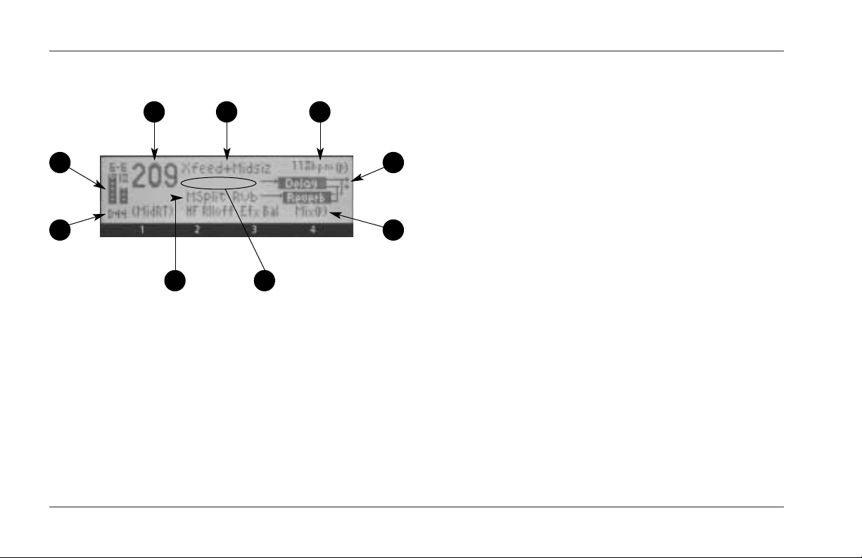
FRONT PANEL DISPLAY
3
1
2
5
1. Input Level Meters
Indicate incoming signal levels. Input level meters
show a minimum when the incoming signal is more
than -48dB digital full-scale. Level meters appear in
inverse video when the signal approaches overload
(-2dB digital full-scale). When signals are between
these extremes, the level meters appear as shown
above.
4 7
9
Input level meters show calibrated values, with 0dB
indicating digital saturation. Markings on the open
portion of each level meter show -6, -18, and -32dB.
The meters have single-pixel precision in which each
pixel represents 2dB.
8
S/PDIF digital input sources that have been mastered
“hot” (at the maximum bit rate) will cause the input
level meters to peak as if digital full-scale is
6
occurring. However, the unit is just receiving the
maximum output from the source, which is loud
enough to peak the meters. This is not a problem as
long as the source audio is not distorted.
Gain reduction from the compressor is indicated by
a descending bar situated between the two input
level meters. It is also calibrated in 2dB increments
per pixel.
2. Input/OVL Indicator
Reflects the input type in normal operation. The first
letter indicates input type, which is selected with the
System Mode parameter Input Source (see page 3-4).
1-6
Page 23

MPX 550
Getting Started
"S" stands for stereo, "L" stands for mono left, "R"
stands for mono right, and "D" stands for digital.
"NoD" appears when digital input is selected, but no
valid digital audio signal is present. The number after
the letter indicates the sample rate (44.1 or 48kHz).
When the processor is in saturation, the letters "OVL"
overwrite the input type indicator. This signals the
need to reduce input levels or the value of a
parameter on the verge of feedback. "OVL" does not
indicate input overload.
3. Program Number
Indicates the number of the program that is loaded.
When a different program is cued, its number will
appear in inverse video below the program number
after a period of time.
4. Program Name
Indicates the name of the selected program.
5. Bank Name
Indicates the name of the selected bank.
6. EDIT Knobs 1 to 4
Indicates the function of EDIT knobs 1 to 4.
7. Tempo
Indicates the current tempo as well as the current
setting of the System Mode parameter Tempo Mode
(see page 3-5) - "P" for Program, "G" for Global. If
the current program is not affected by tempo, this
area of the display will be blank.
8. Routing Configuration
Shows the routing configuration for the selected
program (see page 4-18).
9. Messages
Displays miscellaneous information, such as MIDI
activity, Bypass state, S/PDIF status, etc. When no
messages are required, this area of the display will be
blank (as pictured on the previous page).
1-7
Page 24

Getting Started
Tip
Ring
Sleeve
Tip Sleeve
Ring
Tap
Bypass
REAR PANEL OVERVIEW
Lexicon
1
1. AC Input Connector
Provides power to the unit with the supplied power
cord.
2. MIDI IN and MIDI OUT/THRU
Two 5-pin DIN MIDI connectors are available for
MIDI IN and software-selectable MIDI OUT/THRU.
1-8
2 3 4
6
5
3. FOOTSWITCH
Allows footswitch control of front panel Bypass and
Tap functions. A 1/4 inch Tip/Ring/Sleeve connector
and a momentary contact footswitch are available.
(See page 1-10 for more information.)
Page 25

MPX 550
4. S/PDIF IN and OUT
Provide digital audio input and output. Two RCA
S/PDIF connectors are available. The unit accepts
inputs at 44.1 or 48kHz.
5. ANALOG OUTPUTs
Provide analog audio output. Balanced outputs are
available on either XLR or 1/4 inch Tip/Ring/Sleeve
connectors.
6. ANALOG INPUTs
Provide analog audio input. Balanced inputs are
available on either XLR or 1/4 inch Tip/Ring/Sleeve
connectors.
Getting Started
1-9
Page 26
Getting Started
BYPASS TAP
Lexicon
CONNECTING THE UNIT
The INPUT and OUTPUT connectors on the MPX 550 are
1/4 inch Tip/Ring/Sleeve and XLR sockets. Either may be
used. Connections should be made utilizing high-quality
shielded cables.
The MPX 550 produces effects from either mono or
stereo sources. Either input can be used for mono
sources. It is recommended to use stereo outputs
whenever possible. Only material with Dual Mono
routing is designed for mono outputs. Use either output
connector if mono output is required.
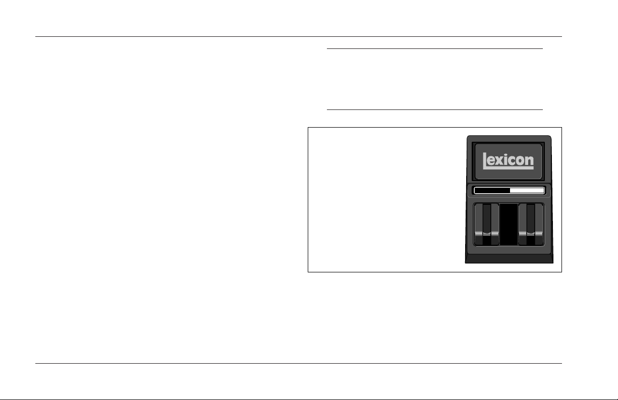
FOOTSWITCH
A footswitch connected to the rear panel FOOTSWITCH
connector can be used to control front panel Tap and
Bypass functions. A momentary footswitch can be wired
to a Tip/Ring/Sleeve connector. A stereo Y-connector
allows two identical switches to be used.
Note:
Power off the unit prior to connecting the
footswitch; otherwise, Bypass functions will be
enabled.
Dual-Function Footswitch
A dual-function footswitch with
a set of labels to indicate Tap
and Bypass functionality is
available at Lexicon dealers or
at www.lexicon.com.
1-10
Page 27

Ch7 Ch8
Aux Send 1
Aux Send 2
RIGHT OutLEFT Out
RIGHT InLEFT In
MPX 550
TYPICAL CONNECTIONS TO A CONSOLE
Getting Started
1-11
Page 28

Getting Started
Lexicon
SETTING AUDIO LEVELS
Note:
As with all audio products, it is good practice to first
power on all outboard equipment, then the mixer,
then the speakers.
INPUT
1. Load Program 1.
2. Set the Mix parameter to Dry (Edit Page 1, EDIT
knob 4).
3. Using high-level program material, begin with a low
input level and advance it slowly.
4. When audible distortion is reached or when the
display clip indicators light and remain lit, lower the
input level until the clip meters appear only on the
highest peaks.
The Input Trim knob allows the unit to be driven by
an input level within a range of +8 to +20dBu. The
minimum setting (fully counterclockwise) should be
optimal for +4dBu (balanced) inputs. The maximum
setting (fully clockwise) should be optimal for
-10dBV (unbalanced) inputs.
OUTPUT
1. Press the front panel System button to activate
System Mode. Output Level, the first System Mode
parameter, will be displayed.
2. Turn EDIT knob 3 to set the Output Level parameter.
Unity gain for a +4dBu input device should be -12dB.
3. Press the System button again to deactivate System
Mode.
1-12
Page 29

2
Basic Operation
Selecting and Loading Programs . . . . . . . . . . . . . . . . . . . . . . . . . 2-2
Editing Programs . . . . . . . . . . . . . . . . . . . . . . . . . . . . . . . . . . . . 2-3
The “Adjust” Parameter. . . . . . . . . . . . . . . . . . . . . . . . . . . . . . . . 2-3
Storing Programs . . . . . . . . . . . . . . . . . . . . . . . . . . . . . . . . . . . . 2-4
The Compressor . . . . . . . . . . . . . . . . . . . . . . . . . . . . . . . . . . . . . 2-5
Tap Tempo . . . . . . . . . . . . . . . . . . . . . . . . . . . . . . . . . . . . . . . . . 2-6
Matching Rhythm • Audio Tap • Global Tempo
Bypass . . . . . . . . . . . . . . . . . . . . . . . . . . . . . . . . . . . . . . . . . . . . 2-7
Page 30

Basic Operation
Lexicon
SELECTING AND LOADING PROGRAMS
When powered on, the unit will load the last program
that was loaded during the previous operating session.
To select another program, turn the front panel
PROGRAM knob.
When the PROGRAM knob is turned clockwise, the unit
will cycle forward through programs in the selected
bank, then proceed to cycle forward through programs
in the next bank. When turned counterclockwise, the
unit will cycle backward through programs in the
selected bank, then proceed to cycle backward through
programs in the previous bank. When the PROGRAM
knob is pushed inward and turned, the unit will cycle
through program banks.
Turn the PROGRAM knob clockwise to
cycle forward through all programs.
Turn the PROGRAM knob counterclockwise to
cycle backward through all programs.
The name and number of the selected program appear
on the front panel display (see page 1-6). The
Load LED will light to indicate that the selected
program is cued for loading. After 4 seconds,
the front panel display will revert to showing the name
and number of the loaded program. However, the Load
LED will remain lit to indicate that the selected program
is still cued for loading. The number of the cued program
will appear in inverse video below the number of the
currently loaded program. To load the cued program,
press the front panel Load button.
The unit can be configured to automatically load
programs 3/4 second after the PROGRAM knob stops
turning. To do this, set the System Mode parameter Auto
Load to Enabled (see page 3-7).
Press and turn the PROGRAM knob to
select a program bank.
2-2
Page 31

MPX 550
Basic Operation
EDITING PROGRAMS
Each program features up to 20 parameters, which are
organized into Edit Pages with as many as four parameters
each. Press the front panel Edit Pages button
to cycle through available Edit Pages for the
loaded program.
Parameters available on the selected Edit Page appear
across the bottom of the front panel display, as shown on
page 1-6. The number below each parameter
corresponds with the number above the Edit knob used
to change its setting. When a parameter setting is
changed, it will appear in inverse video on the front
panel display and the Edit Pages LED will light to show
that the program has been modified. The LED will no
longer be lit when another program is loaded or if the
modified version is stored.
If another program is selected before the modified
program is stored, the edited version will still appear as
the loaded program. However, the Load LED
will light to indicate that a new program is cued
for loading.
THE "ADJUST" PARAMETER
An "Adjust" parameter has been customized for
individual programs, and in most cases controls several
parameters at once to handle complicated editing
processes. For instance, "Adjust" controls the liveness of
space in Chamber and Room programs by changing
Decay, Early Reflections, and EQ simultaneously.
The "Adjust" parameter is located on Edit
Page 1 and controlled with EDIT knob 1. It
appears in parenthesis, such as (MidRT)
pictured at the right. When EDIT knob 1 is
turned, the bottom line of the front panel
display shows a more complete description of the
parameter function in that program. The "Adjust"
parameter is MIDI-compatible with a range of 0 to 127.
2-3
Page 32

Basic Operation
Lexicon
STORING PROGRAMS
The User Bank contains no programs when the MPX 550
is shipped. However, it includes 64 memory locations
available for storing user-modified programs.
To store a program:
1. Press the Store button. The Store and
Tap/Cancel LEDs will light to indicate that
the store function is armed. The first empty
User Bank location will be selected.
To cancel the store function without saving
the program, press the Tap/Cancel button.
This can be done at any time before the
store procedure is completed.
2. Use the PROGRAM knob to select a different User
Bank location. The message area on the front panel
display (see page 1-6) indicates whether the selected
User Bank location is available or empty.
3. The program appears on the front panel with its
original name and a numeric suffix. If desired, use
EDIT knobs 1 and 3 to change the name of the
program.
4. Press the Store button to save the program to the
selected location. The message "Stored" will appear
briefly on the display. The Edit LED will no longer be
lit when the saved version becomes the selected
program.
Note:
When storing a user program, allow the unit to
complete the entire store process before powering
the unit off. If the unit is power cycled during the
process, all previously stored programs may be lost.
2-4
Page 33

MPX 550
Basic Operation
THE COMPRESSOR
The compressor is available in all programs, except
Dynamics. (Dynamics uses a different compression
mechanism, explained on page 4-33.) The compressor
sits in the wet component of the signal in front of the
effects in the loaded program. It is controlled with four
parameters: CmpRatio, Threshld, CmpAttk, and
CmpRels. These parameters are located on the last Edit
Page for each program, except those in the Cmprssr
Bank.
The ratio (CmpRatio) parameter can be set to ratios of
1:1 (off), 2:1, 3:1, 4:1, 5:1, and 10:1. The threshold
(Threshld) parameter can be set within a 0 to -32dB
range. These settings are relative to 0dBFS (digital
saturation). The compressor is disabled if either the ratio
parameter is set to 1:1 or the threshold parameter is set
high enough to prevent the incoming signal from
crossing the compression threshold.
The attack (CmpAttk) and release (CmpRels) parameters
determine how fast the compressor responds, within
3dB of the output level dictated by the incoming signal.
For most music material, the release time should be
about four times longer than the attack time. Both must
be long enough to accommodate the bass content of the
music.
If the compressor is set to react faster than the waveform
of the music itself, the resulting changes in output level
will re-shape the waveform enough to produce
undesirable audio effects. For example, 80Hz has a
period of 12ms. If this is a dominant component in the
music, set both the attack and release parameters to at
least 12ms, even higher for better results. The
compressor acts on both the left and right channels at
the same time, using the sum of the two channels as its
trigger.
Compression presets are available in the Cmprssr Bank
(see page 4-31). For other compression-only effects,
send compressor output into a Dly/Eko program with
the Delay parameter set to 0. The compressor does not
add propagation delay to the audio path. (Note the
converters introduce about 2ms of propagation delay.)
2-5
Page 34

Basic Operation
Lexicon
TAP TEMPO
MATCHING RHYTHM
Tap Tempo can be used to match the delay times and
modulation rates of tempo-based programs with those
of the music. The Tap/Cancel button LED will flash
whenever a tempo-based program is loaded. The current
tempo rate appears in the top-right corner of the front
panel display.
It is not required to enter what "could be" the
delay time in milliseconds. Just press the
Tap/Cancel button twice, and the unit will
calculate the appropriate delay time. To change tempo,
press the Tap/Cancel button twice again in the new
rhythm.
Tempo can also be set with a footswitch (see page 1-10)
or MIDI control device (see page 6-4).
AUDIO TAP
To use audio input to set tempo:
1. Press and hold the Tap/Cancel button until the
message "Detecting audio..." appears at the top of
the front panel display. (The optional dual footswitch
allows the musician to continue playing the
instrument while pressing and holding the Tap
button.)
Tempo parameters available for the loaded program
will also appear on the front panel display.
2. Still holding the Tap/Cancel button, play two short
notes in rhythm.
3. Release the Tap/Cancel button. The message "Knob
3 to change" will appear at the top of the front panel
display to indicate that EDIT knob 3 is now available
to adjust tempo.
2-6
Page 35

MPX 550
Basic Operation
4. If desired, turn EDIT knob 3 to further adjust tempo
in bpm (beats per minute).
5. Press the Tap/Cancel button to exit this mode.
Audio tap is a must for live performances. It offers a
simple method of setting delay times and modulation
rates to match the music.
GLOBAL TEMPO
The Tap/Cancel button LED will flash when a tempocontrolled program is loaded. Most factory presets are
stored with individual tempo rates, which can be
customized to suit personal taste. Tap in the new tempo,
then store the modified version of the program in the
User Bank.
To recall the tempo rate stored with each program, set
the System Mode parameter Tempo Mode (see page 3-5)
to Program. The unit will apply the individual tempo
setting of each program as it is loaded. To apply the
current tempo rate to all programs, set the System Mode
parameter Tempo Mode to Global. The unit will ignore
individual tempo settings and apply the current tempo
setting to each program as it is loaded.
BYPASS
The Bypass button can be used to force the unit
to pass only dry audio, to mute the outputs
immediately, or to mute the inputs to the
loaded program. Its function depends on the setting of
the System Mode parameter Bypass Mode (see page 3-5).
When Bypass Mode is set to Dry, the unit sends only dry,
unprocessed audio to the outputs. When set to Full
Mute, the unit mutes the outputs. When set to Input
Mute, the unit mutes the inputs only. Running effects
will continue their natural decay.
Bypass functions can also be activated with a footswitch
(see page 1-10) or MIDI control device (see page 6-4).
2-7
Page 36

3
System Mode
System Mode Functions . . . . . . . . . . . . . . . . . . . . . . . . . . . . . . . 3-2
Parameters • MIDI Dumps • Restore Default Commands
Page 37

System Mode
Lexicon
SYSTEM MODE FUNCTIONS
System Mode can be used to set System Mode
parameters, execute MIDI Dumps, and restore
default settings. To enter System Mode, press
the front panel System button. The System LED will light
to indicate that System Mode is active.
The tables that begin at the right show System Mode
functions. EDIT knob 1 selects the desired function, and
EDIT knob 3 changes the parameter setting (if
applicable). Changes to System Mode parameters are
effective immediately. MIDI Dumps and Restore Default
Commands require confirmation to execute.
To exit System Mode, press the System button again.
Detailed descriptions of all System Mode functions begin
on page 3-4.
Parameter Settings
Output Level 0dB* to -31dB
Off
Input Source Analog Stereo*
Analog Mono L,
Analog Mono R
S/PDIF Digital
Clock Source Internal 44.1kHz*
Internal 48kHz
External (S/PDIF)
Digital Output Processed*
Dry
Mix Mode Program*
Global
Bypass Mode Dry*
Full Mute
Input Mute
Program Load Mode Bypass Dry*
Full Mute
Tempo Mode Program*
Global
Compressor Mode Program*
Global
3-2
Page 38

MPX 550
System Mode
Parameter Settings (continued)
MIDI Patches Enabled*
Disabled
MIDI Channel Off
1* to 16
Omni
MIDI Program Change Enabled*
Disabled
R1-MPX1
MIDI Clock In Enabled*
Disabled
MIDI Out/Thru Out*
Thru
Operating Mode Normal*
Demo
Locked
Memory Protect Enabled
Disabled*
Auto Load Enabled
Disabled*
Display Brightness –
* Indicates default setting
MIDI Dumps Settings (if applicable)
Dump User Bank 1-16
17-32
33-48
49-64
Dump Current Program –
Dump System Data –
Restore Default Commands
Clear User Bank
Factory Init
3-3
Page 39

System Mode
Lexicon
PARAMETERS
Output Level (0 to -31dB, Off)
Sets output level attenuation within a 0 to -31dB range,
or off.
Input Source
(Analog Stereo; Analog Mono L and R; S/PDIF Digital)
Selects input type. The current selection is indicated in
the lower-left corner of the front panel display. "S" stands
for Analog Stereo, "L" stands for Analog Mono L, "R"
stands for Analog Mono R, and "D" stands for S/PDIF
digital. The number following the prefix indicates the
sample rate (48 or 44.1kHz). "NoD" indicates that no
valid digital audio signal is present.
When set to Analog Stereo, the unit processes signals
from both analog inputs. When set to Analog Mono L,
the unit sends signals from the ANALOG INPUT labelled
LEFT to both processor inputs. When set to Analog Mono
R, the unit sends signals from the ANALOG INPUT
labelled RIGHT to both processor inputs.
When set to S/PDIF Digital, the unit processes signals
from the S/PDIF IN connector. If no valid digital audio
signal is present, the unit will mute and an alert message
will appear on the front panel display.
Note:
When the Input Source parameter is set to S/PDIF
Digital, the Clock Source parameter will
automatically be set to External (S/PDIF).
Clock Source
(Internal 44.1kHz and 48kHz, External (S/PDIF))
Selects the internal or external clock source for the unit.
When set to Internal 44.1kHz, the unit utilizes an internal
clock with a 44.1kHz sample rate. When set to Internal
48kHz, the unit utilizes an internal clock with a 48kHz
sample rate. When set to External (S/PDIF), the unit
utilizes the S/PDIF input signal, even if an analog source
is used. "NoD" will appear in the lower-left corner of the
front panel display if no valid digital input signal is
present to utilize for the external clock.
3-4
Page 40

MPX 550
System Mode
Digital Output (Processed, Dry)
Selects the source for the digital output. When set to
Processed, the digital output is the same as the analog
outputs. Its mix level will reflect the current setting of the
Mix parameter. When set to Dry, the digital output is the
input. This setting is useful for recording dry tracks while
still providing processing at the analog outputs.
Mix Mode (Program, Global)
Controls the mix level that is applied when a new
program is loaded. Mix levels are stored with each
program. When Mix Mode is set to Program, the unit
applies the stored mix level of the selected program to
that program as it is loaded. When set to Global, the unit
ignores stored mix levels and applies the current mix
level to each program as it is loaded.
Bypass Mode (Dry, Full Mute, Input Mute)
Sets the function of Bypass. When set to Dry, the unit
sends only dry, unprocessed audio to the outputs. When
set to Full Mute, the unit mutes the outputs. When set to
Input Mute, the unit mutes the inputs only. Running
effects will continue their natural decay.
Program Load Mode (Bypass Dry, Full Mute)
Controls the processing of incoming audio signals during
program load. When set to Bypass Dry, the unit sends
only dry, unprocessed audio to the outputs. When set to
Full Mute, the unit mutes during program load.
Tempo Mode (Program, Global)
Controls the tempo setting that is applied when a new
program is loaded. A tempo setting is stored with each
program. When Tempo Mode is set to Program, the unit
applies the stored tempo setting of each program as it is
loaded. When set to Global, the unit applies the current
tempo setting to each program as it is loaded.
Compressor Mode (Program, Global)
Controls the compression settings that are applied when
a new program is loaded. Compression settings are
stored with each program. When Compressor Mode is
set to Program, the unit applies the stored setting of
each program as it is loaded. When set to Global, the
unit applies the current compression setting to each
program as it is loaded.
3-5
Page 41

System Mode
Lexicon
MIDI Patches (Enabled, Disabled)
Enables and disables Learned Patches. When set to
Enabled, the unit responds to Learned Patches. When set
to Disabled, the unit ignores Learned Patches,
preventing accidental changes.
MIDI Channel (Off, 1 to 16, Omni)
Selects the MIDI Channel for MPX 550 messages. When
set to Off, the unit ignores messages sent on all MIDI
channels. When set within a range of 1 to 16, the unit
responds to messages sent on the selected MIDI channel.
When set to Omni, the unit responds to messages sent
on all MIDI channels.
MIDI Program Change (Enabled, Disabled, R1-MPX 1)
Enables and disables MIDI Program Change messages.
When set to Enabled, the unit responds to MIDI Program
Change messages. When set to Disabled, the unit
ignores MIDI Program Change messages, preventing
accidental changes. When set to R1-MPX 1, the unit
responds to program change messages from a Lexicon
MPX R1 Foot Controller set to MPX 1 Mode.
MIDI Clock In (Enabled, Disabled)
Enables and disables MIDI Clock messages. When set to
Enabled, Tap Tempo is changed by incoming MIDI
messages. When set to Disabled, the unit ignores MIDI
Clock messages, preventing accidental changes.
MIDI Out/Thru (Out, Thru)
Controls the function of the MIDI OUT/THRU connector.
When set to Out, the unit can generate its own MIDI
Dumps. When set to Thru, the unit can forward - but
cannot generate or modify - MIDI messages.
Operating Mode (Normal, Demo, Locked)
Controls front panel knobs and buttons. When set to
Normal, front panel controls perform their normal
functions. When set to Demo, front panel controls are
placed in a continuous program load cycle for
demonstration purposes. When set to Locked, front
panel controls are locked to their current settings. When
front panel controls are locked:
3-6
Page 42

MPX 550
System Mode
• The front panel PROGRAM knob is still available for
selecting user programs only. Programs stored in the
User Bank are still available, but cannot be modified.
• The System Mode parameter Auto Load is set to
Enabled.
• Bypass functions are still available.
• Tempo and Patches cannot be learned.
• System Mode can still be activated.
Changes to the Operating Mode parameter will not take
effect until the unit has been powered off, then powered
on again.
Memory Protect (Enabled, Disabled)
Protects the User Bank from accidental changes. When
set to Enabled, the unit prevents changes to the User
Bank. However, it does not prevent changes to System
Mode parameters, nor does it prevent the restoration of
factory-default settings. Restoring default settings will
still erase all programs stored in the User Bank. When set
to Disabled, the unit does not prevent changes to the
User Bank.
Auto Load (Enabled, Disabled)
Determines whether the front panel Load button must
be pressed to load selected programs. When set to
Enabled, programs will automatically load 3/4 second
after the PROGRAM knob stops turning. When set to
Disabled, programs will not load until the Load button is
pressed.
Display Brightness
Controls the brightness of the front panel display. Turn
EDIT knob 3 clockwise to make the display darker, and
counterclockwise to make the display brighter.
3-7
Page 43

System Mode
Lexicon
MIDI DUMPS
Dump User Bank (1-16, 17-32, 33-48, 49-64)
Executes a MIDI Dump of User Bank programs to an
external MIDI device, such as a sequencer. These
programs can be dumped back to the unit. This is useful
to preserve User Bank programs from deletion prior to
restoring default settings. User programs are dumped in
groups of 16, depending on the group selected by EDIT
knob 3. Once a group is selected, press the front panel
Store button to execute the Dump. When dumped back,
the group will be returned to its original User Bank
location.
Dump Current Program
Executes a MIDI Dump of the currently active program.
This allows programs to be saved to an external MIDI
device. Press the front panel Store button to execute the
dump. When dumped back, the program will
automatically become the currently active program.
Dump System Data
Executes a MIDI Dump of all System Mode settings and
Learned Patches. Press the front panel Store button to
execute the dump. When dumped back, the System
Mode settings and Learned Patches will take effect
immediately.
3-8
Page 44

MPX 550
RESTORE DEFAULT COMMANDS
Clear User Bank
Arms a procedure to erase the contents of the User Bank.
Press the front panel Store button to execute this
procedure and return the User Bank to its factory-default
condition. This procedure cannot be executed when a
User program is running or when the System Mode
parameter Memory Protect is set to Enabled.
Factory Init
Arms a procedure to restore parameters, System Mode
parameters, User Bank programs, and Learned Patches to
their factory-default conditions. Press the front panel
Store button to execute this procedure.
System Mode
3-9
Page 45

4
Program Descriptions
Single Programs . . . . . . . . . . . . . . . . . . . . . . . . . . . . . . . . . . . . . 4-2
Plate • Gate/Inv • Hall • Chamber • Ambience • Room • Tremolo • Rotary •
Chorus • Flange • Detune • Pitch • Dly/Eko
Special FX. . . . . . . . . . . . . . . . . . . . . . . . . . . . . . . . . . . . . . . . . 4-16
Stereo Stage
Dual Programs . . . . . . . . . . . . . . . . . . . . . . . . . . . . . . . . . . . . . 4-18
Efx Bal • Flng-Dly • Pch-Dly • Chor-Dly • Dly-Rvb • Flng-Rvb • Pch-Rvb •
Chor-Rvb • MSplit Dly • MSplit Rvb • Dual Mono
Cmprssr . . . . . . . . . . . . . . . . . . . . . . . . . . . . . . . . . . . . . . . . . . 4-31
Dynamics . . . . . . . . . . . . . . . . . . . . . . . . . . . . . . . . . . . . . . . . . 4-32
Peak Expansion • Compression • Tape Saturation • Level Meters • Typical
Mastering Dynamics Control Adjustment
Live-FOH (Front of House) . . . . . . . . . . . . . . . . . . . . . . . . . . . . . 4-36
Page 46

Program Descriptions
Lexicon
SINGLE PROGRAMS
PLATE
Plate reverb began with a large, thin sheet of metal
suspended upright under tension on springs.
Transducers attached to the plate transmitted a signal
that made the plate vibrate, causing sounds broadcast
through it to appear to be occurring in a large, open
space.
The Plate programs synthesize the sound of metal plates
with high initial diffusion and a relatively bright, colored
sound. These programs are designed to be heard as part
of the music, mellowing and thickening the sound. Plate
programs are a popular choice for enhancing pop music,
particularly percussion.
Plate Programs "Adjust" Tap
1 Small Plate (Livenes) –
2 Medium Plate (Livenes) –
3 Large Plate (Livenes) –
4 Tap PreDelay (MidRT) PreDelay
(1/32 Note)
5 Tape Slap (ips) –
6 Rich Plate (MidRT) –
7 Large&Bright (MidRT) –
8 VocalPlate (Livenes) Echo
9 Drum Plate (Livenes) –
4-2
Page 47

MPX 550
Program Descriptions
GATE/INV
Gated reverbs were created by feeding a reverb, such as
a metal plate, through an analog gate device. Decay
time was set to instant, while hold time varied duration
and sound.
The Gate programs provide a fairly constant sound with
no decay until the reverb is cut off abruptly. These
programs work well on percussion, particularly on snare
and toms. It is recommended to experiment with other
sound sources as well.
Note:
Adjusting the Time or Duration parameters will
cause the selected program to reload. The System
Mode parameter Program Load Mode determines
whether the system will mute or bypass during
program load.
Gate/Inv Programs "Adjust" Tap
10 StraightGate (Time) –
11 Slope Down (Time) –
12 Drum Gate (HighCut) PreDelay
(1/32 Note)
13 140ms,TapPre (HighCut) PreDelay
(1/32 Note)
14 240ms,TapPre (HighCut) PreDelay
(1/32 Note)
15 340ms,TapPre (HighCut) PreDelay
(1/32 Note)
16 440ms,TapPre (HighCut) PreDelay
(1/32 Note)
17 540ms,TapPre (HighCut) PreDelay
(1/32 Note)
18 Inverse (Time) –
19 Dark Inverse (Time) –
4-3
Page 48

Program Descriptions
Lexicon
HALL
Lexicon’s Hall programs recreate the acoustics of actual
places - from grand, reverberant enclosures to small
concert halls.
The clean reverberation of Hall programs is designed to
add spaciousness without altering source material. In
addition to general instrumental and vocal applications,
the Hall programs give separately recorded tracks a sense
of belonging to the same performance.
Hall Programs "Adjust" Tap
20 Small Hall (MidRT) –
21 Medium Hall (MidRT) –
22 Large Hall (MidRT) –
23 Small Church (MidRT) –
24 Large Church (MidRT) –
25 Jazz Hall (MidRT) –
26 Dance Hall (MidRT) –
27 Synth Hall (MidRT) –
28 Concert Hall (MidRT) –
29 Gothic Hall (MidRT) –
4-4
Page 49

MPX 550
Program Descriptions
CHAMBER
Historically, recording studio chambers were oddly
shaped rooms with a loudspeaker and set of
microphones to collect ambience in various parts of the
room.
Stereo Chamber programs produce even, relatively
dimensionless reverberation with little color change as
sound decays. The initial diffusion is similar to Hall
programs. However, the sense of size and space is much
less obvious. This characteristic, coupled with the low
color of the decay tail, makes these programs useful on
a wide range of material - especially the spoken voice.
Chamber programs give the spoken voice a noticeable
increase in loudness with low color.
Chamber Programs "Adjust" Tap
30 Brick Wall (HighCut) –
31 Basement (HighCut) –
32 LiveConcert (Livenes) Eko Delay
33 Drum Chamber (MidRT) –
34 Moves on . . . (Livenes) –
35 Live Chamber (Livenes) –
36 VocalChambr1 (Livenes) Eko Delay
37 VocalChambr2 (Livenes) Eko Delay
38 WideChamber (Livenes)
39 PCM60: Large (MidRT)
4-5
Page 50

Program Descriptions
Lexicon
AMBIENCE
Ambience adds warmth, spaciousness, and depth to a
performance without coloring its direct sound. It is
commonly used to add a room sound to recorded music
and speech. In music recording, Ambience can
realistically add distance to close-mic’ed signals.
Ambience programs simulate reflections from room
surfaces with random reflections, a gradual decay of
overall level, and a gradual narrowing of bandwidth. In
these programs, the Mix control adds depth - emulating
the movement of a coincident pair of microphones away
from the sound source into the room.
Ambience Programs "Adjust" Tap
40 Announcer (HighCut) –
41 VerySmallAmb (HighCut) –
42 Small Amb (HighCut) –
43 MidSizeAmb (HighCut) –
44 Studio "D" (HighCut) –
45 Bright Amb (Decay) –
46 Dark Amb (Decay) –
47 MarbleFoyer (Livenes) –
48 Smooth Amb (Decay) –
49 Guitar Amb (HighCut) –
4-6
Page 51

MPX 550
Program Descriptions
ROOM
Room programs simulate actual rooms where there is a
strong sense of being in a small, live place. These
programs are useful on drums and percussion, and can
also be applied to electric guitar tracks.
Room Programs "Adjust" Tap
50 Bedroom (Walls) –
51 Tiled Room (LFBoost) –
52 Studio "C" (MidRT) –
53 Small Room (Livenes) –
54 Studio "B" (MidRT) –
55 Rehearsal Rm (EQ) –
56 Studio "A" (MidRT) –
57 Large Room (EQ) –
58 Fat Space (MidRT) –
59 Chunky Space (EQ) –
4-7
Page 52

Program Descriptions
Lexicon
TREMOLO
Tremolo is a rhythmic change in loudness, commonly
employed as an expressive technique by vocalists and
wind instrument players. It is also one of the oldest
effects, frequently used with electric guitar, electric
piano, and occasionally vocals. Different tremolo effects
are largely determined by the rate (fast or slow) and
waveform shape (smooth or sharp) of the change in
loudness. If the effect is used in a stereo mix, the left and
right can be synchronized to produce dramatic side-toside motion.
The Tremolo programs offer classic tremolo shapes, such
as square, sawtooth, triangle, sine, and rectified sine. The
synchronization of the left and right channels can be
adjusted to produce mono and stereo effects. The Tap
button sets tremolo rates, making it simple to match the
tempo of the music. The "Adjust" parameter (Phase) sets
left and right channel waveforms out-of-phase, resulting
in a panning motion.
Set the Mix parameter to Wet for all programs. Mix can
be used to effectively set the depth of the Tremolo
program when more dry is added to the wet-to-dry mix.
It is recommended to make the rate work with the
tempo of the music, as Tremolo is essentially a rhythmic
effect.
Tremolo Programs "Adjust" Tap
60 RectSine Tap (Phase) Rate
(1/8 Note)
61 Square Tap (Phase) Rate
(1/8 Note)
62 Sine TapTrpl (Phase) Rate
(1/4 Note)
63 Triangle (Phase) –
64 Sawtooth (Phase) –
4-8
Page 53

MPX 550
Program Descriptions
ROTARY
Rotary speaker cabinets were designed to provide a
majestic vibrato/choir effect for electronic theater and
church organs. The most well-known rotary speaker is
the Leslie™ Model 122, which has two counter-rotating
elements: a high-frequency horn and a low-frequency
drum with slow and fast speeds. The sound generated as
the spinning elements change speed is truly magical.
The swirling, spacious effect is difficult to describe - but
immediately recognizable.
The Rotary programs are a detailed simulation of a Lesliestyle cabinet. The input signal is split into high and
low-frequency bands. The rotation effect is created by a
synchronized combination of pitch shifting, tremolo,
and panning. Like the physical cabinet, the high (horn)
and low (drum) frequencies are "spun" in opposite
directions. Horn and drum speeds are independent, and
designed with acceleration and deceleration
characteristics to simulate the inertia of the original
mechanical elements.
A virtual requirement for organ music, Rotary programs
also sound remarkable with guitar and electric piano
rhythm parts. In fact, these programs are great
alternatives to chorus and tremolo effects for any sound
source.
To achieve the full effect, set the Mix parameter to Wet
for all programs.
Rotary Programs "Adjust" Tap
65 Rot:SlowFast (Switch) –
66 Rot Slow (Resnce) –
67 Rot SpeedAdj (Speed) –
68 Rot TapRate1 (Balance) Rate
69 Rot TapRate2 (Resnce) Rate
4-9
Page 54

Program Descriptions
Lexicon
CHORUS
Chorus effects create lush, full sounds by multiplying the
original audio source. Traditionally, these effects were
used to fatten up tracks and to add body to guitar
without coloring the original tone. Chorus effects are
also often combined with plates, echoes, and other
reverb effects.
The stereo Chorus programs, inherited from Lexicon’s
PCM 80, create a rich, airy effect that simulates the
sound of multiple sources from a single source. These
programs are stunning on acoustic or clean electric
guitar.
These programs utilize six independently randomized
delay voices panned across the stereo field. Set the Mix
parameter to Wet to achieve the full richness of the
6-voice chorus.
Chorus Programs "Adjust" Tap
70 Chorus1 (Resnce) –
71 Chorus2 (HighCut) –
72 Chorus3 (Diffusn) –
73 Slap Chorus1 (Diffusn) –
74 Slap Chorus2 (Depth) –
4-10
Page 55

MPX 550
Program Descriptions
FLANGE
Flange effects were originally created by simultaneously
playing back identical programs on two tape recorders,
then using hand pressure against the flange of the tape
reels to slow down first one machine, then the other. The
result was a series of changing phase cancellations and
reinforcements, with characteristic swishing, tunneling,
and fading sounds.
The stereo flanger has two 2-Tap delays - one per
channel. The first tap is fixed, and the second sweeps
past it. Mixing the two delay taps together creates the
flanging effect.
Set the Mix parameter to Wet to achieve the full flange
effect of these programs.
Flange Programs "Adjust" Tap
75 Flng Lite (Rate) –
76 Flng Lite180 (Resnce) –
77 Flng Med180 (Rate) –
78 Flng Deep (Resnce) –
79 Flng Deep180 (Resnce) –
4-11
Page 56

Program Descriptions
Lexicon
DETUNE
Detune effects create delayed and pitch-shifted versions
of the original source, thickening the sound. This creates
a particularly effective simulation of double-tracking.
These effects are also great alternatives to Chorus effects,
adding the richness of a chorus without the audible
sweep caused by the chorus rate.
The 4-voice stereo Detune programs have one pair of
voices per channel. As more detune is applied with the
"Adjust" parameter, the pair become more out of tune,
providing a lush sound without the need for mixing in a
dry signal.
Set the Mix parameter to Wet to achieve the full effect of
these programs.
Detune Programs "Adjust" Tap
80 Detune Mild (Dtuning) –
81 Detune (Dtuning) –
Med&Warm
82 Detune Heavy (Dtuning) –
83 Det Xtreme (Dtuning) –
84 Pitch Detune (Dtuning) –
4-12
Page 57

MPX 550
Program Descriptions
PITCH
Altering the pitch of a sound produces a wide range of
effects - from subtle detuning, to harmonies, to chords.
The stereo polyphonic Pitch programs can be used to
shift program material or monophonic sources within a
range of one octave up to two octaves down.
For pitch correction, set the Mix parameter to Wet. For
harmonization, set the Mix parameter to the desired
setting.
Pitch Programs "Adjust" Tap
85 Pch Chrmatic (Pitch) –
86 Pitch Fine (Pitch) –
87 Pch 4th-5ths (Pitch) –
88 Pch PowerInv (Inversn) –
89 Vocal Chorus (HighCut) –
4-13
Page 58

Program Descriptions
Lexicon
DLY/EKO
Delays and echoes repeat a sound a short time after it
first occurs. The simplest (and oldest) delay effect is tape
slap - a single repeat about 100ms after the original
sound. Tape slap was often used on Elvis Presley’s voice
and rockabilly guitar tracks.
Tape slap becomes tape echo when the output of the
tape is fed back into the input (feedback). This turns a
single repeat into a series of repeats, each a little softer
and a little darker than the last. This darkening is
characteristic of the analog tape recording process.
Digital echoes do not have this characteristic; each
repeat has the same exact timbre. For digital echoes,
loudness is the only difference from repeat to repeat.
Tape and digital echoes are both useful, but different.
Tape echo is warmer, allowing the original sound to
distinguish itself. Digital echo presents a "perfect" copy
of the original sound.
The DLY/EKO programs include mono (5.5 seconds),
stereo (2.7 seconds), and 6-voice multi-tap effects. Each
program can be used for tape or digital delay or echo
effects. When the "Adjust" parameter (Edit Page 1, EDIT
knob 1) is set to a value between 0 and 63, digital delay
effects are produced. Each repeat is the same timbre, but
softer. When the "Adjust" parameter is set to a value
between 64 and 127, tape effects are produced. Each
repeat is darker and softer.
In programs 90 to 97, the "Adjust"
MIN
parameter sets the amount of
feedback with an increasing number
of repeats as the setting is increased.
Delay time is set with Tap. Each
Delays
MAX
Echoes
MAX
program is preset with a different useful rhythm. In
programs 98 to 104, the amount of feedback is preset
and the "Adjust" parameter determines the delay time.
With all delay and echo effects, note the way the repeats
fall rhythmically to the beat. The most effective delay
and echo patterns are those that lock with the tempo of
the music.
4-14
Page 59

MPX 550
Program Descriptions
In all delay programs and dual programs, the unit uses
the MstrDly parameter to scale delay times that are not
controlled by Tempo. In some programs, the "Adjust"
parameter controls MstrDly.
MstrDly can be set within a range of 0 to 100%. It is
usually set to 100% in most presets. When MstrDly is set
manually (or by the "Adjust" parameter) to less than
100%, individual delay times will scale accordingly. For
example, if MstrDly is set to 25%, all delay times will be
reduced to 1/4 of their normal value. Knobs that control
those delay times will become correspondingly less
sensitive - requiring, in this example, four times as many
clicks to obtain the normal result.
Dly/Eko Programs "Adjust" Tap
90 Dly Mono Tap (FeedBk) Delay Time
91 DlyStereoTap (FeedBk) Delay Time
92 Dly ShuflTap (FeedBk) Delay Time
93 Dly Dot8 Tap (FeedBk) Delay Time
94 Dly 8+3plTap (FeedBk) Delay Time
95 Dly Pong Tap (FeedBk) Delay Time
96 Dly XFbkTap1 (FeedBk) Delay Time
97 Dly XFbkTap2 (FeedBk) Delay Time
98 Dly Mono (Time) –
99 Dly Stereo (Time) –
100 Dly TapeSlap (Time) –
101 Multi Bounce (Time) –
102 MultiInverse (Time) –
103 Multi Linear (Time) –
104 Multi Pong (Time) –
4-15
Page 60

Program Descriptions
Lexicon
SPECIAL FX
Special FX Programs "Adjust" Tap
105 Infinite (HighCut) Eko
106 The Abyss (Dtuning) –
107 Jet Flange (Resnce) Speed (Whole Note)
108 Verb>Chorus (HighCut) –
109 TapRot Dly (Time) Rate (Drum/Horn)
110 Fader Verb (Level) Echo
111 Low Rumble (Decay) –
112 Ducker Verb (Decay) –
113 DuckerChorus (Resnce) –
114 Stereo Stage (Width) –
115 Echoes:Beats (Delay) Delay Time
116 Panning Dlys (FeedBk) Dly Time, Pan Rate
117 DreamSequenc (Pitch) –
118 Infinite Dly (FeedBk) Delay Time (Whole Note)
119 Diffusor (Diffusn) –
4-16
Page 61

MPX 550
Program Descriptions
STEREO STAGE
Stereo Stage provides stereo reverb while preserving the
dry signal. To use this program, note the following:
• Use the MPX 550 in line between the mixer and
house amplifiers - not as an effect mixed back into
the main left and right channels on the mixer.
• Pan the input channels on the mixer fully to each
musician’s side of the stage.
• Keep the Mix parameter set to 50% (the default
Program Load Mode setting).
• Adjust reverb level by setting the Efx Bal parameter
between 100:0% (full left) and 60:40%.
• The ideal setting for the Width parameter depends
on the distance between the speakers at each side of
the stage. The program loads with an assumed
spacing of about 20 feet, with an adjustment range
of 10 to 50 feet. The width setting assumes that
most audience members are seated within about 30
degrees to either side of the stage centerline. If
audience members are seated further to the sides of
the stage, the setting can be increased. Otherwise, it
should be kept as low as possible.
4-17
Page 62

Program Descriptions
Dual Stereo (Parallel)
Flange
Delay
L
R
L
R
Mono Split
Flange
Delay
L
R
L
R
Dual Mono
Flange
Delay
L
R
L
R
Cascade
Flange Delay
L
R
L
R
Lexicon
DUAL PROGRAMS
The dual programs combine Delay with Reverb, or either
Delay or Reverb with Flange, Pitch, or Chorus. Four
routing configurations are used in the variations of each
dual program: Dual Stereo (Parallel), Cascade, Mono
Split, and Dual Mono.
• Flng-Dly, Pch-Dly, Chor-Dly, Dly-Rvb, Flng-Rvb,
Pch-Rvb, and Chor-Rvb
The first six programs in these banks feature two effects
arranged in Dual Stereo (Parallel) configuration. Both
effects receive signals from the left and right inputs,
and both effects send signals to the left and right
outputs. The last four programs in these banks feature
two effects arranged in Cascade configuration. The
first effect passes its signal to the second effect. For
example, in Flng-Dly, Flange passes its signal to Delay.
• MSplit Dly, MSplit Rvb
These banks contain programs that are arranged in
Mono Split configuration, which is similar to the
Dual Stereo (Parallel) configuration. One effect (e.g.
Flange) receives signals from the left input and the
other effect (e.g. Delay) receives signals from the
right input. However, both effects send signals to the
left and right outputs.
• Dual Mono
This bank contains programs that are arranged in the
Dual Mono configuration. One effect (e.g. Flange)
receives input from the left channel only and sends
output to the left channel only. The other effect (e.g.
Delay) receives input from the right channel only
and sends output to the right channel only.
4-18
Page 63

MPX 550
Program Descriptions
EFX BAL
The Efx Bal parameter controls the relative balance of
each effect in the dual programs. In Cascade variations,
the parameter also varies the amount of the first effect or
dry signal fed into the second effect.
50:50%: Provides delayed pitch shift.
Pitch
75:25%:
Provides pitch shift, plus delayed pitch shift.
Pitch
100:0%: Provides pitch shift.
Pitch
Delay
The illustration below uses the Pch-Dly program to show
the effect of the Efx Bal parameter at certain settings
when a Cascade variation is selected.
Delay
25:75%:
Provides delayed pitch shift, plus delayed dry signal.
Pitch
0:100%: Provides delayed dry signal.
Pitch
Delay
DelayDelay
4-19
Page 64

Program Descriptions
Dual Stereo (Parallel)
Flange
Delay
L
R
L
R
Cascade
Flange Delay
L
R
L
R
Lexicon
FLNG-DLY
Flng-Dly Programs "Adjust" Tap Routing
120 Flng Tap (FeedBk) Delay Time (1/4 Note) Dual Stereo (Parallel)
121 Flng .8Tap (FeedBk) Dotted (1/8 Note) Dual Stereo (Parallel)
122 Flng 3plTap (FeedBk) Triplet (1/8 Note) Dual Stereo (Parallel)
123 Flng PongTap (FeedBk) Delay Time (1/4 Note) Dual Stereo (Parallel)
124 Flng Xfeed (Time) – Dual Stereo (Parallel)
125 Flng Bounce (Time) – Dual Stereo (Parallel)
126 Flng > Tap (FeedBk) Delay Time (1/4 Note) Cascade
127 Flng > Fbk (Time) – Cascade
128 Flng > Pong (FeedBk) Delay Time (1/4 Note) Cascade
129 Flng > Bnce (Time) – Cascade
4-20
Page 65

MPX 550
Dual Stereo (Parallel)
Pitch
Delay
L
R
L
R
Cascade
Pitch Delay
L
R
L
R
Program Descriptions
PCH-DLY
Pch-Dly Programs "Adjust" Tap Routing
130 5th Tap (Pitch) Delay Time Dual Stereo (Parallel)
131 8ve 3pl Tap (Pitch) Delay Time Dual Stereo (Parallel)
132 8ve 8+3plTap (Pitch) Delay Time Dual Stereo (Parallel)
133 3rd4thPong (Pitch) Delay Time Dual Stereo (Parallel)
134 4th5th Xfeed (Pitch) Delay Time Dual Stereo (Parallel)
135 5th6th Xfeed (Pitch) Delay Time Dual Stereo (Parallel)
136 8ve > Xfeed (Pitch) Delay Time Cascade
137 5th > Xfeed (Pitch) Delay Time Cascade
138 MajMin > Fbk (Pitch) Delay Time Cascade
139 StepUp > Tap (Pitch) Delay Time Cascade
4-21
Page 66

Program Descriptions
Dual Stereo (Parallel)
Chorus
Delay
L
R
L
R
Cascade
Chorus Delay
L
R
L
R
Lexicon
CHOR-DLY
Chor-Dly Programs "Adjust" Tap Routing
140 Chor Tap (FeedBk) Delay Time Dual Stereo (Parallel)
141 Chor .8Tap (FeedBk) Delay Time Dual Stereo (Parallel)
142 Chor 8+3pl (FeedBk) Delay Time Dual Stereo (Parallel)
143 Chor Pong (FeedBk) Delay Time Dual Stereo (Parallel)
144 Chor Repeat (Time) – Dual Stereo (Parallel)
145 Chor Bounce (Time) – Dual Stereo (Parallel)
146 Chor > Tap (FeedBk) Delay Time Cascade
147 Chor >Repeat (Time) – Cascade
148 Chor > Pong (FeedBk) Delay Time Cascade
149 Chor > Bnce (Time) – Cascade
4-22
Page 67

MPX 550
Dual Stereo (Parallel)
Delay
Reverb
L
R
L
R
Cascade
Delay Reverb
L
R
L
R
Program Descriptions
DLY-RVB
Dly-Rvb Programs "Adjust" Tap Routing
150 Tap Small (MidRT) Delay Time Dual Stereo (Parallel)
151 3plTap MidSz (MidRT) Delay Time Dual Stereo (Parallel)
152 8+3pl Large (MidRT) Delay Time Dual Stereo (Parallel)
153 Pong Small (Decay) Delay Time Dual Stereo (Parallel)
154 Xfeed MidSz (Decay) Delay Time Dual Stereo (Parallel)
155 Xfeed Large (Decay) Delay Time Dual Stereo (Parallel)
156 Tap > Room (Livenes) Delay Time Cascade
157 8+3pl >Large (MidRT) Delay Time Cascade
158 Xfeed > Room (Livenes) Delay Time Cascade
159 Xfeed >Large (MidRT) Delay Time Cascade
4-23
Page 68

Program Descriptions
Dual Stereo (Parallel)
Flange
Reverb
L
R
L
R
Cascade
Flange Reverb
L
R
L
R
Lexicon
FLNG-RVB
Flng-Rvb Programs "Adjust" Tap Routing
160 LiteFl Small (MidRT) Speed (Whole Note) Dual Stereo (Parallel)
161 LiteFl MidSz (MidRT) Speed (Whole Note) Dual Stereo (Parallel)
162 LiteFl Large (MidRT) – Dual Stereo (Parallel)
163 DeepFl Small (MidRT) – Dual Stereo (Parallel)
164 DeepFl MidSz (MidRT) – Dual Stereo (Parallel)
165 DeepFl Large (MidRT) – Dual Stereo (Parallel)
166 LiteFl>Small (MidRT) Speed (Whole Note) Cascade
167 LiteFl >Room (Livenes) Speed (Whole Note) Cascade
168 DeepFl>Large (MidRT) – Cascade
169 DeepFl >Room (Livenes) – Cascade
4-24
Page 69

MPX 550
Dual Stereo (Parallel)
Pitch
Reverb
L
R
L
R
Cascade
Pitch Reverb
L
R
L
R
Program Descriptions
PCH-RVB
Pch-Rvb Programs "Adjust" Tap Routing
170 3rd4th Room (Pitch) – Dual Stereo (Parallel)
171 4th5th Room (Pitch) – Dual Stereo (Parallel)
172 5th6th Room (Pitch) – Dual Stereo (Parallel)
173 8ve MidSiz (Pitch) – Dual Stereo (Parallel)
174 Power MidSiz (MidRT) – Dual Stereo (Parallel)
175 Detune Room (Dtuning) – Dual Stereo (Parallel)
176 Fine > Small (Pitch) – Cascade
177 Power >Large (MidRT) – Cascade
178 4th > MidSiz (MidRT) – Cascade
179 8ve > MidSz (MidRT) – Cascade
4-25
Page 70

Program Descriptions
Dual Stereo (Parallel)
Chorus
Reverb
L
R
L
R
Cascade
Chorus Reverb
L
R
L
R
Lexicon
CHOR-RVB
Chor-Rvb Programs "Adjust" Tap Routing
180 Chor1 Small (MidRT) – Dual Stereo (Parallel)
181 Chor1 MidSiz (MidRT) – Dual Stereo (Parallel)
182 Chor1 Large (MidRT) – Dual Stereo (Parallel)
183 Chor2 Small (MidRT) – Dual Stereo (Parallel)
184 Chor2 MidSiz (MidRT) – Dual Stereo (Parallel)
185 Chor2 Large (MidRT) – Dual Stereo (Parallel)
186 Chor1 > Room (Livenes) – Cascade
187 Chor2 > Room (Livenes) – Cascade
188 Chor3 > Room (Livenes) – Cascade
189 Chor1 >Small (MidRT) – Cascade
4-26
Page 71

MPX 550
Program Descriptions
MSPLIT DLY
MSplit Dly Programs "Adjust" Tap Routing
190 Flng + Tap (FeedBk) 1/4 Note Mono Split
191 Flng + Pong (FeedBk) 1/4 Note Mono Split
192 Flng + Xfeed (Time) – Mono Split
193 Flng + Bnce (Time) – Mono Split
194 DeepFl + Dly (Time) – Mono Split
195 5th + Tap (Pitch) Delay Time Mono Split
196 8ve + 3plTap (Pitch) Delay Time Mono Split
197 4th5th+Xfeed (Pitch) Delay Time Mono Split
198 5th6th+Xfeed (Pitch) Delay Time Mono Split
199 PchFine +Tap (Pitch) Delay Time Mono Split
200 Chor + Tap (FeedBk) Delay Time Mono Split
201 Chor + Pong (FeedBk) Delay Time Mono Split
202 Chor + Xfeed (Time) – Mono Split
203 Chor + Bnce (Time) – Mono Split
204 Chor+Inverse (Time) – Mono Split
Note: The Mono Split routing configuration is illustrated on page 4-18.
4-27
Page 72

Program Descriptions
MSPLIT RVB
MSplit Rvb Programs "Adjust" Tap Routing
205 Tap + MidSiz (MidRT) Delay Time Mono Split
206 Pong + Large (MidRT) Delay Time Mono Split
207 Bnce + MidSz (MidRT) Delay Time Mono Split
208 Xfeed + Small (MidRT) Delay Time Mono Split
209 Xfeed+MidSiz (MidRT) Delay Time Mono Split
210 LiteFl+MidSz (MidRT) – Mono Split
211 LiteFl+Large (MidRT) – Mono Split
212 DeepFl+Small (MidRT) – Mono Split
213 DeepFl+MidSz (MidRT) – Mono Split
214 DeepFl +Room (Livenes) – Mono Split
215 4th5th +Room (Pitch) – Mono Split
216 5th6th +Room (Pitch) – Mono Split
217 4ths + Large (MidRT) – Mono Split
218 8ve + MidSz (MidRT) – Mono Split
219 PchFin+MidSz (Pitch) – Mono Split
220 Chor1 +Small (MidRT) – Mono Split
Lexicon
4-28
Page 73

MPX 550
MSplit Rvb Programs "Adjust" Tap Routing
221 Chor1+ Large (MidRT) – Mono Split
222 Chor2+MidSiz (MidRT) – Mono Split
223 Chor2+ Large (MidRT) – Mono Split
224 Chor3+MidSiz (MidRT) – Mono Split
Note: The Mono Split routing configuration is illustrated on page 4-18.
Program Descriptions
4-29
Page 74

Program Descriptions
DUAL MONO
Dual Mono Programs "Adjust" Tap Routing
225 Tap | Small (MidRT) Delay Time Dual Mono
226 Tap | MidSiz (MidRT) Delay Time Dual Mono
227 Tap | Large (MidRT) Delay Time Dual Mono
228 Tap | Room (Livenes) Delay Time Dual Mono
229 DeepFl | Tap (FeedBk) Speed (1/4 Note) Dual Mono
230 DeepFl | Dot8 (FeedBk) Speed (Dotted 1/4 Note) Dual Mono
231 8ves | Tap (Pitch) Delay Time Dual Mono
232 8ves | 3pl (Pitch) Delay Time Dual Mono
233 Chor2 | Tap (FeedBk) Delay Time Dual Mono
234 Chor2 | Dot8 (FeedBk) Delay Time Dual Mono
235 LiteFl | Large (MidRT) Speed Dual Mono
236 DeepFl | Large (MidRT) – Dual Mono
237 8ves | MidSz (MidRT) – Dual Mono
238 4ths | Large (MidRT) – Dual Mono
239 Chor1 | Room (Livenes) – Dual Mono
Note: The Dual Mono routing configuration is illustrated on page 4-18.
Lexicon
4-30
Page 75

MPX 550
Program Descriptions
CMPRSSR
In all Cmprssr programs, the "Adjust" parameter controls
gain within a range of 0 to 9.5dB. It can be used to
match volume levels between the dry, bypassed, and
compressed output obtained with typical music
material.
If the System Mode parameter Mix Mode is set to
Program, the Mix parameter will automatically be set to
Wet, allowing the compressed delay signal to be the only
output signal present. If the System Mode parameter
Mix Mode is set to Global, the Mix parameter must be
set manually.
The five compressor-reverb presets offer a reverb
component in parallel with a zero-delay dry component.
The compressor acts on both. The Mix parameter should
be set to Wet, and the effective mix should be adjusted
with the Efx Bal parameter.
Comprssr Programs "Adjust" Tap
240 Two to One (Gain) –
241 Three to One (Gain) –
242 3:1 Small (Gain) PreDelay
243 5:1 Medium (Gain) PreDelay
244 3:1 Large (Gain) PreDelay
245 GuitarComp (Gain) –
246 Limiter (Gain) –
247 Male Vocal (Gain) PreDelay
248 Female Vocal (Gain) PreDelay
* Presets 240, 241, 245, and 246 are compressor only. Presets 242, 243,
244, 247, and 248 are combination compressor and reverb with Dual
Stereo (Parallel) routing.
4-31
Page 76

Program Descriptions
Lexicon
DYNAMICS
Note:
A few seconds after the Dynamics preset is loaded,
the Dynamics name will flash briefly on the front
panel display. This does not affect audio input or
output.
Dynamics is intended for use in the studio, when
dynamic processing of stereo signals is required. Because
of its long delay, this preset is not recommended for use
in a live performance or as a mix insert. It includes effects
that perform peak expansion, compression, and tape
saturation in that order.
Dynamics includes nine parameters that are divided into
three Edit Pages. Peak expansion settings are controlled
on the first page, compression settings are controlled on
the second page, and tape saturation settings are
controlled on the third page. The first page also features
a switch that selects between gain reduction and input
metering.
PEAK EXPANSION
Peak expansion is used to raise the overall level of sound
sources that rise above the adjustable peak expansion
threshold. In performances with a wide dynamic range,
peak expansion can increase the level of low-level sound
sources. For example, for a relatively quiet instrument
that swells in volume without the desired impact, peak
expansion can raise the instrument level during the swell.
ExpThrsh (-31 to 0dB)
Controls the threshold above which expansion is
applied. Lower settings enable low-level sound sources
to expand. Higher settings enable only very high-level
peaks to expand.
ExpLvl (0.0dB to 5.89dB)
Controls the amount of expansion that is applied to
sound sources that rise above the expansion threshold.
The parameter setting defines the maximum increase in
signal level due to expansion. Higher settings increase
the level of expansion applied. Maximum expansion is
applied to signals that rise well above the expansion
threshold for longer than 50ms.
4-32
Page 77

MPX 550
Program Descriptions
Meters (GR, In)
Selects between gain reduction (GR) and input level (In)
metering. (See page 4-35 for more information.)
COMPRESSION
Compression is used to lower the overall level of sound
sources that rise above an adjustable compression
threshold. Compression can be used to match the levels
of louder sources to those of quieter sources.
Ratio (1:1 to 10:1)
Determines the level of gain reduction applied when the
sound source rises above the compression threshold. It
can be set in ratios of 1:1, 1.60:1, 2.00:1, 2.66:1, 3.20:1,
4.00:1, 5.33:1, 8.00:1 and 10:1. For each dB rise in input
to the compressor, the ratio indicates the fraction of the
dB rise in output. For example, when Ratio is set to
4.00:1, the output will rise 0.25dB for each dB rise in
input to the compressor. Higher settings will result in
more compression.
Thresh (-31 to -0dB)
Designates the compression threshold, the level the
sound source must rise above before compression is
applied.
Attack (200 to 3.0msec)
Determines how fast the compressor responds to sound
sources that rise above the compression threshold.
Slower settings allow the signal to rise above the
threshold for short periods of time with minimal
compression.
Release (4.0 to .30sec)
Determines how fast compression is reduced when
sound sources fall below the compression threshold.
Slower settings reduce compression gradually. Faster
settings reduce compression more quickly, causing the
level of the sound source to be tracked more closely.
. . . continued on page 4-34
4-33
Page 78

Program Descriptions
Lexicon
TAPE SATURATION
Tape saturation emulates the sound of sources recorded
on analog tapes and sources recorded digitally. Because
of the natural peak saturation that occurs with analog
tapes, sound sources recorded on them seem louder
than the same sound sources recorded digitally. To use
this effect, increase the Gain parameter setting. The
amount of gain used is guided by both the output level
meter and, more importantly, the ear. Gain levels that
are too high can dramatically reduce the dynamic range
of sound sources, possibly causing objectionable
distortion - just like real tape.
Gain (Min, 1 to 30, Max)
Determines average output level. Lower settings prevent
signal saturation. Higher settings reduce peaks within the
sound source relative to the average level of the sound
source, enabling the peak saturation block to reduce
peak levels. The setting can be increased to its maximum
level without causing digital overload. However,
excessive peak saturation may distort the signal.
Saturation (Off, Modern, Vintage)
Controls the amount of saturation.
LEVEL METERS
1
2
1
2
1. Output Level Meter
Indicates output levels. The value indicates the
maximum output level of the left or right channel,
whichever is greater. The tick marks are placed in
3dB increments. The right most tick mark indicates
0dB or maximum output level.
3
4
4-34
Page 79

MPX 550
Program Descriptions
2. Peak Expansion Meter
Indicates the level of peaks above the peak
expansion threshold. Low-level peaks are shown as
one or two graduated bars. Slightly higher peaks of
longer duration are shown as three graduated bars.
High-level peaks are shown as three solid bars.
Note:
Use the Meters parameter to select between gain
reduction and input level metering.
3. Gain Reduction Meter
When the Meters parameter is set to GR, indicates
the output level reduction due to compression. The
value shown indicates the maximum left or right
channel gain reduction, whichever is greater.
The meter moves from right to left. The tick marks
are placed in 3dB increments. The right-most tick
mark represents 0dB or no gain reduction. Each tick
mark proceeding from right to left indicates an
additional 3dB of gain reduction.
4. Input Meter
When the Meters parameter is set to In, indicates the
maximum left or right channel input levels,
whichever is greater. The associated tick marks are
placed in 3dB increments. The right-most tick mark
indicates 0dB or maximum input level.
TYPICAL MASTERING DYNAMICS CONTROL
ADJUSTMENT
The following is a common scenario for musical sources
that have not previously been compressed:
• For analog input sources, adjust the front panel
Input Trim knob so the input meters peak in the -6dB
range. The input meters should never exceed the
0dB level.
• Beginning at 0dB, reduce the setting of the ExpThrsh
parameter until peaks in the source material cause
the peak expansion level meter to show 1 to 3
graduated bars. High-level peaks in the sound source
. . . continued on page 4-36
4-35
Page 80

Program Descriptions
Lexicon
Typical Mastering Dynamics Control Adjustment (continued)
will cause the peak expansion meter to show three
solid bars for short periods of time. Increase the
ExpLvl parameter until the peaks in the source
material sound slightly exaggerated. Then, reduce
the setting until the peaks sound natural.
• Set the Ratio parameter to 4.00:1, the Attack
parameter to 7.2msec, and the Release parameter to
1.4sec. Beginning at 0dB, reduce the setting of the
Thresh parameter until the gain reduction meter
moves between 0 and 3 to 6dB of gain reduction. If
the output level sounds unnatural, increase the
settings of the Attack and Release parameters. If
output levels are too low after peaks occur, increase
the setting of the Release parameter. If output levels
are still too low after peaks occur, increase the
setting of the ExpLvl parameter.
• Beginning at 0, adjust the Gain parameter setting
until the output level meter shows peaks above
–3dB.
LIVE-FOH (FRONT OF HOUSE)
Live-FOH programs are designed for live performances,
with controls that are more convenient for live-sound
engineers to operate. These programs use Dual Mono
routings to accommodate the sound reinforcement
systems (PAs) used in most small-to-mid-sized venues.
Often, these systems provide limited channels and mono
aux sends for effects.
For Live-FOH presets:
• Edit Page 1 contains the four most essential
parameters for the first effect, and Edit Page 2
contains the four most essential parameters for the
second effect. Non-essential parameters have been
removed from the Edit Pages.
4-36
Page 81

MPX 550
Program Descriptions
• In the delay programs, two delay level controls have
been combined into the "Adjust" parameter: (Tap/
Dly). These programs contain two delays. The first is
controlled by tempo and generally used to create
longer delays and echoes. The second is set
manually with the Delay parameter, and can be used
to create a "slap" of 60 to 135ms.
The (Tap/Dly) parameter provides an inverse level
control for these delays. The default setting provides
equal levels of each. The tempo-controlled delay is
suited for longer rhythm-sensitive effects, while the
manually-controlled delay is suited for shorter times.
However, both delays are capable of delivering a full
range of delay times that can be crossfed into each
other for more extreme effects.
• The Dly/Reverb program is available with alternative
EDIT knob assignments (255). The first two Edit
Pages are arranged with delay parameters on the left
and reverb parameters on the right. This
arrangement splits effect controls left-to-right rather
than page-to-page.
Live-FOH Programs "Adjust" Tap
250 Flange/Dly (Tap/Dly) Delay Time
251 Chorus/Dly (Tap/Dly) Delay Time
252 Flange/Rvb (Tap/Dly) –
253 Chorus/Rvb (Tap/Dly) –
254 Dly/Reverb (Tap/Dly) Delay Time
255 Dly/Reverb (Tap/Dly) Delay Time
4-37
Page 82

5
Parameter Descriptions
Parameter Graphics. . . . . . . . . . . . . . . . . . . . . . . . . . . . . . . . . . . 5-2
Parameter Glossary . . . . . . . . . . . . . . . . . . . . . . . . . . . . . . . . . . . 5-4
Page 83

Parameter Descriptions
Lexicon
PARAMETER GRAPHICS
The MPX 550 features graphic enhancements for each parameter, which appear on the front panel display whenever
a parameter setting is changed. These graphics illustrate the point at which the selected setting falls within the entire
parameter range, and provide a visual indication of the parameter’s function. As the setting changes, the graphic also
changes to reflect the new setting. Examples are shown below and on the following page. To view other parameter
graphics, change the setting of the desired parameter.
When the Decay parameter setting is changed, the graphics pictured below appear.
When the HF Rlloff parameter setting is changed, the graphics pictured below appear.
5-2
Page 84

MPX 550
When the Mix parameter setting is changed, the graphics pictured below appear.
When a delay parameter setting is changed, the graphics pictured below appear.
When the Level parameter setting is changed, the graphics pictured below appear.
When the Width parameter setting is changed, the graphics pictured below appear.
Parameter Descriptions
5-3
Page 85

Parameter Descriptions
Lexicon
PARAMETER GLOSSARY
Note:
System Mode parameters are described in Section 3.
Dynamics parameters are described on pages 4-32
to 4-35. These parameters are not included in this
glossary.
"Adjust" (0 to 127)
Functions differently from preset to preset. "Adjust" is a
"magic" control that can manipulate several parameters
at once or provide a set of special values for a single
control. For example, it may be called (Fast) or (Slow) for
a parameter that is also settable to any value via another
control. "Adjust" has a range of 0 to 127 to provide a
convenient attachment point for a MIDI controller.
Attack (0 to 100 or 0 to 255)
Controls the sharpness of the initial response to an input
signal. High settings cause explosive sounds, while low
settings cause sounds to build up more slowly with time.
Attack only affects the level of sound within the first
50ms or so.
5-4
Balance (-100 to +100%)
In Rotary programs, determines the volume balance
between the horn and drum.
BassMult (0.2 to 4.0x)
Controls the reverb time for low-frequency signals.
BassMult works as a multiplier of the Decay and MidRT
parameters. For example, if BassMult is set to 2.0x, and
Decay is set to 2 seconds, the low-frequency reverb time
will be 4 seconds. For a natural-sounding hall ambience,
BassMult should be set between 1.0x and 2.0x.
BassXvr (28Hz to 19.4kHz, off)
Sets the frequency below which BassMult applies.
CmpAttk (4 to 125msec)
Controls the speed at which the compressor responds
when input signals increase above threshold.
CmpRatio (1:1 (off) to 10:1)
Sets the ratio of gain reduction for input signals above
threshold.
Page 86

MPX 550
Parameter Descriptions
CmpRels (4 to 250msec)
Controls the rate at which the compressor relaxes when
compressed input signal levels fall.
Decay (73ms to 19.61sec or 24ms to 6.53sec)
Controls reverb time for mid frequency signals. In
Ambience programs, Decay controls the length of the
ambience "tail".
Depth (0 to 100%)
Controls the level of volume modulation.
Diffusion (0 to 100%)
Controls the degree to which initial echo density
increases over time. High settings result in a high initial
buildup of echo density. (Echo density is also affected by
Size, with smaller spaces sounding denser.)
Dly Fbk (0 to 100%)
Serves as a master control determining the feedback of
left into left and right into right.
Dly HiCut (28Hz to 19.4kHz, off)
Appears in Dual programs where one effect is Dly/Eko,
providing independent control over the Dly/Eko
high-frequency output. Dly HiCut applies a high-cut
filter similar to HF Rlloff to the Delay/Echo effect.
Dly Lvl (off, -24dB to 0dB)
Controls the overall level of the signal fed into the Delay,
Echo effect.
Dly Lvl 1, 2, 3 (off, -48dB to 0dB)
Controls the levels of voice set 1, 2, or 3 for both the left
and right channels.
Dly XFbk (0 to 100%)
Determines the feedback of left into right and right into
left.
5-5
Page 87

Parameter Descriptions
Lexicon
DlyTapLvl (off, -48 to 0dB)
Appears in dual programs where one effect is Delay/Echo
and one or more delay voice is controlled by Tap.
DlyTapLvl controls the level of the Tap-controlled voice
that is mixed into the Delay/Echo effect.
Drum Dep (0 to 100%)
In Rotary programs, determines the amount of
modulation produced by the drum.
Drum Res (-100 to +100%)
In Rotary programs, determines the amount of
resonance, i.e. signal, fed back into the effect.
Duration (140 to 700ms)
In Gate/Inv programs, determines the length of time that
passes before the output is cut off.
Efx Bal (100:0% to 0:100%)
Controls the relative amounts of the two effects in Dual
programs. In a Dual Stereo (Parallel), Mono Split, or Dual
Mono configuration, this splits the signal to be fed into
the two effects. In a Cascade configuration, it also allows
some of the signal to bypass either of the two effects.
EkoDly L, R (0ms to 1.198sec)
Control the timing of single reflections that occur early in
the decay in the reverb programs. These reflections
simulate the sound sometimes heard off the back wall of
a stage or other reflective surface.
EkoFbk L, R (-100 to 100%)
Control the amount of repeating echo that simulates a
flutter echo between parallel walls in the reverb
programs. The range of these parameters is from -100%
to 100%, with negative values producing a polarity
reversal. High settings can cause signal overload.
HF Rlloff (28Hz to 19.4kHz, off)
Sets the high-frequency cutoff of a low-pass filter.
5-6
Page 88

MPX 550
Parameter Descriptions
HighSlope and LowSlope (-16 to +15)
Determine the shape of the reverb envelope for low
frequencies. HighSlope and LowSlope are found only in
the Gate/Inv programs. When LowSlope is set to 0, the
level of low reverb remains unchanged over its duration,
then cuts off abruptly. Setting LowSlope above 0 causes
the level of low-frequency reverb to rise smoothly from
soft to loud until the sound is cut off. The greater the
slope, the softer the initial reverberation and the more
pronounced its rise. When set to a negative value, the
low-frequency reverb drops to a quieter level before
cutoff. HighSlope is similar to LowSlope, but applies to
middle and high frequencies.
Horn Dep (0 to 100%)
In Rotary programs, determines the amount of
modulation produced by the horn.
Horn Res (-100 to +100%)
In Rotary programs, determines the amount of
resonance, i.e. signal fed back into the effect.
Intrvl (Varies)
Controls the amount of pitch-shift applied. Intrvl values
are in semi-tones. Pch values are in Cents (1/100th of a
semi-tone). These values are additive.
L Dly 1, 2, 3 (0ms to 5.060sec)
Sets the delay time of left voice 1, 2, or 3. The Dly/Eko
effect has three independent voices on each side.
Level (0 to 100%)
Determines the amount of wet signal present in the
output. It functions similar to Mix, except it affects the
wet component only. Level is generally used to balance
the overall output of two or more programs when Mix is
set to wet.
LowSlope and HighSlope (-16 to +15)
See HighSlope and LowSlope.
5-7
Page 89

Parameter Descriptions
Lexicon
Mix (Dry, 1 to 99%, Wet)
Mix controls the ratio of unprocessed (Dry) and
processed (Wet) signal in the output. When the MPX 550
is patched into a console, this parameter should almost
always be set to Wet.
MstrRate (0 to 100%)
In Rotary programs, serves as a master rate control
affecting both the horn and drum rates.
Pch Fbk (L), (R) (-100% to +100%)
Controls the amount of feedback through the Pitch presets, resulting in repeated echoes with pitch progressing
up or down.
Pch (L), (R/S) (-2400 to 2600)
Control the amount of pitch-shift applied to the left and
right channels. For true stereo programs, the Pch(L)
parameter is not available and the Pch(R/S) parameter
means stereo. For mono programs, the Pch(L) and (R/S)
parameters mean left and right respectively.
Pitch-shifting requires some time shifting. A true stereo
(not merely Dual Mono) signal contains components
that are common to the left and right signals. A proper
stereo image is maintained only if the phase relationship
between the left and right signals is maintained. This
requires that the exact same computation be applied to
both channels, which is why only one control is provided for Pitch presets.
PDly (L), (R) (0 to 100ms)
Controls the amount of "look-ahead" required by the
pitch-shift algorithm. Some amount of pre-delay is
always in effect, even when this parameter is set to 0.
Phase (0 to 270deg)
Determines the relative timing between the left and right
channels.
PreDelay (0ms to 1.198sec)
Controls the time delay between the input of signal and
the onset of reverberation.
5-8
Page 90

MPX 550
Parameter Descriptions
R Dly 1, 2, 3 (0ms to 5.060sec)
Sets the delay time of right voice 1, 2, or 3. The Dly/Eko
effect has three independent voices on each side.
Rate (0 to 50.05Hz)
Controls modulation speeds.
Res 1, 2 (-100 to +100%)
In Chorus programs, control the amount of feedback
signal.
Resonanc (-100 to +100%)
In Flange programs, controls the amount of feedback.
Rt HC (28Hz to 19.4kHz, off)
Sets the frequency above which high frequencies are
rolled off in the reverberated signal, causing reverberated
signals to grow progressively darker. This results in a
more natural sound because it simulates the effect of air
absorption in a real hall. Setting this parameter to a
low- frequency dampens the audio as it re-circulates, and
consequently can actually shorten the reverb time.
RvbLvl (off, -48dB to 0dB)
In Ambience programs, controls the amount of "extra"
longer-decay reverb added to the effect. In Ambience,
short-decay early reflections create a real-room sound.
Shape (0 to 255)
Controls the buildup of the early reflections that most
audibly create the sound of a real room. Shape and
Spread work together; if either is set to 0, the other has
no effect.
Size (4.0 to 76.0m)
Sets the rate of echo density buildup after the initial
period (which is controlled by Diffusion). It also acts as a
master control for Decay. Size changes a reverb sound
from very small to very large. It is recommended to set
the Size control to the approximate size of the acoustic
space that is being created before adjusting other
parameters. The size in meters is roughly equal to the
longest dimension of the space. (Adjusting the Size
parameter causes the program to re-load.)
5-9
Page 91

Parameter Descriptions
Lexicon
Speed (0 to 5000)
In Flange programs, controls how rapidly the two
"flange" voices move.
Speed 1, 2 (0 to 5000)
In Chorus programs, control the rates at which the
various voices sweep through frequency.
Spread (0 to 255)
Controls the timing between the initial reflections that
most audibly create the sound of a real room. Shape and
Spread work together; if either is set to 0, the other has
no effect.
Sweep (0 to 100ms)
In Flange programs, determines the maximum amount
of time-delay applied to each voice.
Sweep 1, 2 (0 to 100ms)
In Chorus programs, control the amount of frequency
variation for two different collections of voices. (The
Chorus effect simulates six voices with slightly varying
pitch. Separate controls are available over two sets of
three voices each.)
Threshld (-32 to -0dB)
Controls the level above which signals are compressed.
Tune 1, 2 (0 to 100%)
In Detune programs, determines the amount of
detuning applied to voices 1 and 2.
5-10
Page 92

MPX 550
Wavform (See Below)
In Tremolo programs, determines volume modulation.
Settings are defined as follows:
Setting Description
Sine Smooth modulation with polarity reversal.
Rectified Smooth modulation with no polarity
Sine reversal.
Triangle Linear ramp up and down.
Sawtooth Linear ramp up with sudden reduction.
Square Level modulates between maximum
and minimum.
Width (0 to 100%)
Determines the effective separation between the left and
right channels.
Parameter Descriptions
5-11
Page 93

6
MIDI Operation
Learn Mode . . . . . . . . . . . . . . . . . . . . . . . . . . . . . . . . . . . . . . . . 6-2
MIDI Channel Assignment . . . . . . . . . . . . . . . . . . . . . . . . . . . . . . 6-2
Program Change Messages . . . . . . . . . . . . . . . . . . . . . . . . . . . . . 6-3
Loading Programs • Activating Bypass or Tap Functions
Continuous Controllers . . . . . . . . . . . . . . . . . . . . . . . . . . . . . . . . 6-4
MIDI Clock . . . . . . . . . . . . . . . . . . . . . . . . . . . . . . . . . . . . . . . . . 6-6
MIDI Dumps. . . . . . . . . . . . . . . . . . . . . . . . . . . . . . . . . . . . . . . . 6-6
Sysex Messages. . . . . . . . . . . . . . . . . . . . . . . . . . . . . . . . . . . . . . 6-7
MIDI Implementation Chart. . . . . . . . . . . . . . . . . . . . . . . . . . . . . 6-8
Page 94

MIDI Operation
Lexicon
LEARN MODE
Learn Mode enables the MPX 550 to "learn" MIDI
Program Change and Continuous Controller messages.
To activate and deactivate Learn Mode, press the Store
and Tap/Cancel buttons simultaneously. The Store and
Tap/Cancel LEDs will light to indicate that Learn Mode is
active. The front panel display will then show the current
patching for EDIT knobs 1 to 4 (Edit Page 1). To access
knobs 5 to 20, press the Edit Pages to cycle to the desired
Edit Page.
The unit supports learned patches for Bypass and Tap, as
well as all available parameters controlled with the front
panel Edit knobs.
The parameters controlled with the EDIT
knobs can be patched to Continuous
Controller messages.
Press the Store and Tap/Cancel
buttons simultaneously to activate
and deactivate Learn Mode.
MIDI CHANNEL ASSIGNMENT
A single, selectable MIDI channel is used for all MPX 550
messages. This channel can be assigned in System Mode
with the MIDI Channel parameter.
Note:
A MIDI channel should be assigned before MIDI
features are used.
Program Change
messages can be used
to load programs.
Bypass and Tap/Cancel can be
patched to Program Change and
Continuous Controller messages.
6-2
Page 95

MPX 550
MIDI Operation
PROGRAM CHANGE MESSAGES
LOADING PROGRAMS
Standard MIDI Program Change messages can be used
to load all 255 presets and 64 user programs. The unit
conforms to the use of MIDI Continuous Controller 32 to
execute Bank Select messages. MPX 550 program banks
are ordered numerically from 0 to 27, beginning with
the Plate Bank. (See the table at the right for additional
bank numbers.)
Any program can be loaded by selecting its bank with
Controller 32, then sending the appropriate Program
Change message.
For example, if the Plate Bank is selected:
• Sending Program Change 1 will load the first Plate
program (Small Plate).
• Sending Controller 32 with a value of 27 followed by
Program Change 1 will load the first program in the
User Bank.
MIDI Program Banks
0 Plate
1 Gate/Inv
2 Hall
3 Chamber
4 Ambience
5 Room
6 Tremolo
7 Rotary
8 Chorus
9 Flange
10 Detune
11 Pitch
12 Dly/Eko
13 Special FX
14 Flng-Dly
15 Pch-Dly
16 Chor-Dly
17 Dly-Rvb
18 Flng-Rvb
19 Pch-Rvb
20 Chor-Rvb
21 MSplit Dly
22 MSplit Rvb
23 Dual Mono
24 Cmprssr
25 Dynamics
26 Live-FOH
27 User
• Sending Controller 32 with a value of 1 followed by
Program Change 2 will load the second program
(Slope Down) in the Gate/Inv Bank.
Once a bank is selected, all subsequent Program Change
messages will select programs within that bank until a
new value for Controller 32 is received, or until another
program or bank is selected with the front panel
PROGRAM knob.
MIDI Program Change messages can be disabled in
System Mode with the MIDI Program Change
parameter.
6-3
Page 96

MIDI Operation
Lexicon
ACTIVATING BYPASS OR TAP FUNCTIONS
The unit can recognize MIDI Program Change messages
100 to 127 (101 to 128 on some MIDI devices) for
activating Bypass or Tap functions.
To assign a Program Change message to the Bypass or
Tap controls:
1. Simultaneously press the Store and Tap buttons to
activate Learn mode.
2. Press the desired front panel button - Bypass or Tap.
The front panel display will indicate the current
patch on the selected control.
3. Send the MIDI Program Change message to the
MPX 550. The front panel display will indicate the
new patch on the control, and "Stored" will appear
briefly in the message area.
4. Press the Store button to commit the assignment.
5. Simultaneously press the Store and Tap buttons to
deactivate Learn Mode.
Some MIDI controllers do not allow repeated Program
Change messages to be sent with a single button. To
assist these controllers, the unit also recognizes the next
highest Program Change message with each Program
Change message it learns for Bypass and Tap. For
instance, if Program Change 20 is learned as the source
for Bypass, Program Change 21 will also control Bypass
functions. To avoid conflicting Bypass and Tap
assignments, leave a space between the assignments of
these two buttons.
CONTINUOUS CONTROLLERS
The unit recognizes Pitch Bend, AfterTouch, and MIDI
Continuous Controllers 1 to 31 and 33 to 119.
To learn a Continuous Controller:
1. Simultaneously press the Store and Tap buttons to
activate Learn mode.
6-4
Page 97

MPX 550
MIDI Operation
2. Turn the desired EDIT knob or press the desired
button on the front panel. The front panel display
will indicate which control is selected, as well as the
current controller range.
3. Select the desired controller using one of the
following methods:
A. Move the MIDI controller through its full range.
To use a portion of the controller range, limit this
movement to the desired range. The message
area on the front panel display will indicate
incoming MIDI activity.
B. Rotate the EDIT knob until the desired Controller
number is displayed. The full range of the
Controller (0 to 127) will be assumed. This
method is not available for Bypass and Tap.
4. Press the Store button to commit to the assignment.
The word "Stored" will appear briefly in the message
area of the front panel display.
5. To assign another front panel control, repeat steps 2
to 4.
6. Simultaneously press the Store and Tap buttons to
deactivate Learn Mode.
Note:
When a MIDI controller is assigned to the Bypass
control, moving the controller above the mid-point
of its learned range engages Bypass. Moving the
controller below the mid-point range disengages
Bypass. When a MIDI controller has been assigned
to the Tap control, moving the controller above the
mid-point of its learned range will "tap" the control
as if the Tap button had been pressed.
6-5
Page 98

MIDI Operation
Lexicon
MIDI CLOCK
The unit recognizes MIDI Clock messages and applies
the tempo (40 to 400bpm) to programs that use Tap
Tempo. Connect a MIDI device that outputs MIDI Clock,
such as the MPX R1 foot controller or a MIDI sequencer,
to the MPX 550 MIDI IN connector to have the MPX 550
automatically recognize and begin to process MIDI Clock
messages. When the tempo of the connected device
changes, the unit will automatically adjust its delay times
and modulation rates to match the new tempo.
This feature can be disabled with the System Mode
parameter MIDI Clock In.
Note:
When System Mode is active, the unit will not
respond to MIDI Clock messages. Once System
Mode is deactivated, the unit will resume
responding to MIDI Clock messages.
MIDI DUMPS
MIDI Dumps can be used to save the user programs, the
selected program, or the System Mode settings and
Learned Patch assignments to a storage device (typically
a MIDI sequencer). MIDI Dumps are performed in
System Mode (see page 3-8).
To perform a dump of the user programs, the selected
program, or the System Mode settings and Learned
Patches:
1. Press the front panel System button. The System LED
will light to indicate that System Mode is active.
2. Use the EDIT knob 1 to select:
• Dump User Bank
Executes a dump of user programs. Use Edit
knob 3 to select the desired range of user
programs: (1-16), (17-32), (33-48), or (49 to
64). When a user program dump is returned to
the unit from a MIDI storage device, the unit
saves it in the appropriate User Bank locations.
6-6
Page 99

MPX 550
MIDI Operation
• Dump Current Program
Executes a dump of the selected program.
• Dump System Data
Executes a dump of System Mode settings and
Learned Patch assignments.
3. Press Store to execute the dump.
4. Press System to deactivate System Mode.
Note:
MIDI Dumps will not be executed unless the System
Mode parameter MIDI Out/Thru is set to Out (see
page 3-6).
SYSEX MESSAGES
MIDI Sysex messages can be used to access all algorithm
parameters. More information about using this advanced
feature with the MPX 550 and other Lexicon products is
available at www.lexicon.com. The website offers
instructions, sample messages, and a complete table of
parameter Sysex addresses.
Note:
Executing MIDI Sysex messages is a complicated
process. Please observe the cautionary notes
included on the website.
6-7
Page 100

MIDI Operation
Lexicon
MIDI IMPLEMENTATION CHART
Function Transmitted Recognized Remarks
Basic Default X 1 Selected in System Mode
Channel Channel X 1-16
Mode Default Mode 2
Messages X X
Altered X
Note True Voice X X
Number
Velocity Note ON X X (Off=9n, v=0)
Note OFF X X
After Keys X X Used as controller
Touch Channels X OX Selected in System Mode
Pitch X OX Used as controller
Blender Learned
Control X OX 1 to 119 (0 to 32 used as Bank Select)
Change Learned
6-8
 Loading...