

Page 1
Page 2
Important Safety Instructions
Save these instructions for later use.
• Always use with the correct line voltage. Refer to the manufacturer's operating instructions for power requirements. Be advised that different operating voltages may require the
use of a different line cord and/or attachment plug.
• Do not install the unit in an unventilated rack, or directly above heat producing equipment such as power amplifiers. Observe the maximum ambient operating temperature listed
in the product specification.
• Slots and opening on the case are provided for ventilation – to ensure reliable operation and prevent it from overheating. These openings must not be blocked or covered. Never
push objects of any kind through any of the ventilation slots. Never spill a liquid of any kind on the unit.
• Never attach audio power amplifier outputs directly to any of the unit's connectors.
• To prevent shock or fire hazard, do not expose the unit to rain or moisture, or operate it where it will be exposed to water.
• Do not attempt to operate the unit if it has been dropped, damaged, exposed to liquids, or if it exhibits a distinct change in performance indicating the need for service.
This unit should only be opened by qualified service personnel. Removing covers will expose you to hazardous voltages.
• Take precautions not to defeat the grounding or polarization of the unit's power cord.
• Do not overload wall outlet, extension cords or integral convenience receptacles, as this can result in a risk of fire or electrical shock.
• Route power supply cords so that they are not likely to be walked on or pinched
by items placed on or against them, paying particular attention to cords at plugs,
convenience receptacles, and the point at which they exit from the unit.
• The unit should be cleaned only as recommended by the manufacturer.
Communications Notice
This equipment generates and uses radio frequency energy and if not installed and used properly, that is, in strict accordance with the manufacturer's instructions, may cause interference to radio
and television reception. It has been type tested and found to comply with the limits for a Class B computing device in accordance with the specifications in Subpart J of Part 15 of FCC Rules,
which are designated to provide reasonable protection against such interference in a residential installation. However, there is no guarantee that interference will not occur in a particular installation. If this equipment does cause interference to radio or television reception, which can be determined by turning the equipment OFF and ON, the user is encouraged to try to correct the interference by one or more of the following measures:
• Reorient the receiving antenna • Relocate the computer with respect to the receiver
• Move the computer away from the receiver • Plug the computer into a different outlet so that the computer and receiver are on different branch circuits.
If necessary, the user should consult the dealer or an experienced radio/television technician for additional suggestions. The user may find the following booklet prepared by the Federal
Communications Commission helpful: "How to identify and Resolve Radio/TV Interference Problems." This booklet is available from the U.S. Government Printing Office, Washington DC 20402,
Stock No. 004-000-00345-4.
Outdoor Antenna Grounding
If an outside antenna is connected to the receiver, be sure the antenna system is grounded to provide protection against voltage surges and built-up static charges.
Section 810 of the National Electrical Code, ANSI/NFPA No. 70-1984, provides information with respect to proper grounding of the mast and supporting structure,
grounding of the lead-in wire to an antenna-discharge unit, size of grounding conductors, location of antenna-discharge unit, connection to grounding electrodes,
and requirements for the grounding electrode. See illustration.
Power Lines
An outside antenna should be located away from power lines.
© 2000 Lexicon, Inc. All Rights Reserved.
Lexicon, Inc. | 3 Oak Park | Bedford, MA 01730-1441 USA | Tel 781-280-0300 | Fax 781-280-0490 | e-mail info@lexicon.com | www.lexicon.com
Lexicon Part No. 070-14738 | Rev 1 | 03/01
Printed in the United States of America
This triangle, which appears on your component,
alerts you to the presence of uninsulated,
dangerous voltage inside the enclosure;
voltage that may be sufficient to
constitute a risk of shock.
CAUTION
RISK OF ELECTRIC SHOCK
DO NOT OPEN
This triangle, which appears on your component,
alerts you to important operating and
maintenance instructions in this
accompanying literature
Ground
Clamp
Electric
Service
Equipment
NEC - National Electrical Code
Antenna
Lead-In Wire
Antenna Discharge
Unit (NEC Section
810-20)
Gounding Conductors
(NEC Section 810-21)
Ground Clamps
Power Service Grounding
Electrode System
(NEC Art 250, Part H)
A Harman International Company
Page 3
ii
Lexicon Part No. 070-14738 | Rev 1 | 03/01
© 2001 Lexicon, Inc. Bedford, MA USA All rights reserved.
The information contained in this document is subject to change without notice and should not be construed as a commitment by
Lexicon, Inc. Lexicon, Inc. assumes no responsibility for any errors that may appear in this document.
A Harman International Company
Lexicon, Inc
3 Oak Park
Bedford, MA 01730 USA
Tel 781-280-0300 Fax 781-280-0490
Customer Support Fax 781-280-0499
www.lexicon.com
Page 4

iii
Introduction
MPX 200
International Safety Instructions . . . . . . . . . . . . .v - ix
Instrucciones importantes de seguridad
Instructions de Sûreté Importantes
Importanti norme di sicurezza
Instruções de Segurança importantes
Wichtige Sicherheitsanweisungen
Vigtig information om sikkerhed
Tärkeitä turvallisuusohjeita
Viktig informasjon om sikkerhet
Viktiga säkerhetsföreskrifter
Important User Information . . . . . . . . . . . . . . . . .x-xii
La Información del Usuario importante
L'Information de l'Utilisateur importante
Informazioni di Utente importanti
Informação de Usuário importante
Wichtiger Benutzer Information
Section 1 - Getting Started
Overview . . . . . . . . . . . . . . . . . . . . . . . . . . . . . . . . . . . .1-1
Front Panel Details and Usage . . . . . . . . . . . . . . . . . .1-2
Rear Panel Details and Usage . . . . . . . . . . . . . . . . . . .1-3
Input and Output . . . . . . . . . . . . . . . . . . . . . . . . . . . . .1-4
Setting Audio Levels . . . . . . . . . . . . . . . . . . . . . . . . . . .1-4
Section 2 - Basic Operation
The Adjust Knob . . . . . . . . . . . . . . . . . . . . . . . . . . . . . .2-1
Selecting and Loading Programs . . . . . . . . . . . . . . . .2-1
Cueing Programs . . . . . . . . . . . . . . . . . . . . . . . . . . . . .2-2
Editing Programs . . . . . . . . . . . . . . . . . . . . . . . . . . . . . .2-2
The Program Parameters . . . . . . . . . . . . . . . . . . .2-3
Tempo Features . . . . . . . . . . . . . . . . . . . . . . . . . . . . . .2-4
Tap . . . . . . . . . . . . . . . . . . . . . . . . . . . . . . . . . . . . .2-4
Audio Tap . . . . . . . . . . . . . . . . . . . . . . . . . . . . . . . .2-4
Global Tempo . . . . . . . . . . . . . . . . . . . . . . . . . . . .2-4
Setting Tempo via MIDI . . . . . . . . . . . . . . . . . . . . .2-5
The Compressor . . . . . . . . . . . . . . . . . . . . . . . . . . . . . .2-5
The Compressor Parameters . . . . . . . . . . . . . . . . .2-6
Bypass . . . . . . . . . . . . . . . . . . . . . . . . . . . . . . . . . . . . . .2-7
Storing Programs . . . . . . . . . . . . . . . . . . . . . . . . . . . . .2-7
Selecting and Loading User Programs . . . . . . . . . . . .2-8
ES
FR
IT
DE
PT
US
DK
FI
NO
SE
ES
FR
IT
DE
PT
US
Page 5

iv
Introduction
Lexicon, Inc.
Section 3 - System Mode
Overview . . . . . . . . . . . . . . . . . . . . . . . . . . . . . . . . . . . .3-1
System Mode Parameters . . . . . . . . . . . . . . . . . . . . . .3-2
Section 4 - Program Descriptions
Overview . . . . . . . . . . . . . . . . . . . . . . . . . . . . . . . . . . . .4-1
MPX 200 Programs . . . . . . . . . . . . . . . . . . . . . . . . . . . .4-2
About the Dual Programs . . . . . . . . . . . . . . . . . . . . .4-17
Section 5 - MIDI Operation
MPX 200 MIDI Behavior . . . . . . . . . . . . . . . . . . . . . . . . .5-1
Assigning a MIDI Channel for Program Load . . . . . . .5-1
MIDI Bank Select and Program Change Messages . .5-1
Learning Other MIDI Patches . . . . . . . . . . . . . . . . . . . .5-2
Clearing a Learned Assignment . . . . . . . . . . . . . . . . .5-3
MIDI Clock . . . . . . . . . . . . . . . . . . . . . . . . . . . . . . . . . .5-4
MIDI Dumps . . . . . . . . . . . . . . . . . . . . . . . . . . . . . . . . .5-4
MIDI Implementation . . . . . . . . . . . . . . . . . . . . . . . . . .5-5
Appendix
MPX 200 Specifications . . . . . . . . . . . . . . . . . . . . . . . .A-1
Declaration of Conformity . . . . . . . . . . . . . . . . . . . . .A-2
Page 6
v
Introduction
MPX 200
English
Important Safety Instructions
Save these instructions for later use.
Follow all instructions and warnings marked on the unit.
Always use with the correct line voltage. Refer to the manufacturer’s operating instructions for the power requirements. Be advised that different operating voltages require
the use of a different line cord and/or attachment plug.
Do not install this unit in an unventilated rack, nor directly above items that generate
heat, such as power amplifiers. Observe the maximum ambient operating temperature
listed in the product specification.
The openings on the case are provided for ventilation; to ensure reliable operation and
prevent it from overheating, these openings must not be blocked or covered. Never
push objects of any kind through any of the ventilation slots. Never spill any liquids on
the unit.
Never attach audio power amplifier outputs directly to any of the unit’s connectors.
To prevent shock or fire hazard, do not expose the unit to rain or moisture, or operate it
where it will be exposed to moisture. Do not attempt to operate the unit if it has been
dropped, damaged, exposed to liquids, or if it exhibits a distinct change in performance indicating the need for service. This unit should only be opened by qualified service personnel. Removing covers will expose you to hazardous voltages.
This triangle, which appears on your component, alerts you to the presence of uninsulated, dangerous voltage inside the enclosure…voltage
that may be sufficient to constitute a risk of shock.
This triangle, which appears on your component, alerts you to important
operating and maintenance instructions in this accompanying literature.
Portuguese
Instruções de Segurança importantes
Economize estas instruções para uso posterior.
Siga todas as instruções e advertências marcadas na unidade.
Sempre use com a voltagem de linha correta. Se refira ao fabricante está operando
instruções para as exigências de poder. Seja aconselhado que voltagens operacionais
diferentes requeiram para o uso uma corda de linha diferente ou tomada de anexo.
Não instale esta unidade em uma prateleira de unventilated, nem diretamente sobre
artigos que geram calor, como amplificadores de poder. Observe o máximo que temperatura operacional ambiente listou na especificação de produto.
São providas as aberturas no caso para ventilação; assegurar operação segura e
impedir isto de aquecer demais, não devem ser bloqueadas estas aberturas ou
devem ser cobertas. Nunca empurre objetos de qualquer amável por quaisquer das
aberturas de ventilação. Nunca derrame qualquer líquido na unidade.
Nunca prenda amplificador de poder auditivo produz diretamente a quaisquer dos
conectores da unidade.
Prevenir choque ou perigo de incêndio, não exponha a unidade para chover ou umidade, ou opera isto onde será exposto a umidade. Não tente operar a unidade se foi
derrubado, estragado, exposto a líquidos, ou se exibe uma mudança distinta em
desempenho que indica a necessidade por serviço. Esta unidade só deveria ser aberta através de pessoal de serviço qualificado. Removendo coberturas o exporão a voltagens perigosas.
Este triângulo que se aparece em seu componente o alerta à presença de uninsulated, voltagem perigosa dentro do enclosure…voltage que pode ser suficiente para constituir um risco de choque.
Este triângulo que se aparece em seu componente o alerta a operando importantes e instruções de manutenção nesta literatura acompanhante.
US
PT
Page 7
vi
Introduction
Lexicon, Inc.
Deutsch
Wichtige Sicherheitsanweisungen
Heben Sie sich diese Sicherheitsanweisungen auch für später auf.
Befolgen Sie alle auf der Vorrichtung stehenden Anweisungen und Warnungen.
Immer nur mit der richtigen Spannung verwenden! Die Gebrauchsanweisungen des
Herstellers informieren Sie über die elektrischen Anforderungen. Vergessen Sie nicht daß
bei verschiedenen Betriebsspannungen ggf. auch verschiedene Leitungskabel
und/oder Verbindungsstecker zu verwenden sind.
Stellen Sie die Vorrichtung nicht in ein unbelüftetes Gestell oder unmittelbar über
wärmeerzeugende Geräte wie z.B. Tonverstärker. Halten Sie die in den
Produktspezifikationen angegebene maximale Umgebungstemperatur bei Betrieb ein.
Schlitze und Öffnungen im Gehäuse dienen der Belüfung; um verläßlichen Betrieb
sicherzustellen und Überheizen zu vermeiden dürfen diese Öffnungen nich verstopft
oder abgedeckt werden. Stecken Sie nie irgend einen Gegenstand durch die
Belüftungsschlitze. Vergießen Sie keine Flüssigkeiten auf den Apparat.
Dieses Produkt is mit einem 3-drahtigen Erdungsstecker ausgerüstet. Diese
Sicherheitsmaßnahme darf nicht unwirksam gemacht werden.
Schließen Sie nie Tonverstärker unmittelbar an einen Anschluß des Apparates an.
Um elektrischen Schlag oder Feuer zu vermeiden, setzen Sie den Apparat weder Regen
noch Feuchtigkeit aus und betreiben Sie ihn nicht dort wo Wasser eindringen könnte.
Versuchen Sie nicht den Apparat zu betreiben falls er fallen gelassen, beschädigt, oder
Flüssigkeiten ausgesetzt wurde, oder falls sich seine Arbeitsweise derart ändert daß
daraus ein Bedarf nach Raparatur zu schließen ist.
Dieser Apparat sollte nur von qualifizierten Fachleuten geöffnet werden. Das
Abnehmen von Abdeckungen setzt Sie gefährlichen Spannungen aus.
Dieses Dreieck auf Ihrem Apparat warnt Sie vor nicht-isolierter,
gefährlicher Spannung im Gehäuse ... stark genug um eine
Berührungsgefahr darzustellen.
Dieses Dreieck auf Ihrem Apparat bedeutet daß wichtige Betriebsund Wartungsanweisungen in der mitgelieferten Dokumentation zu
finden sind.
Español
Instrucciones importantes de seguridad
Guarde esta instrucciones para uso posterior.
Utilice siempre el voltaje correcto. Diríjase a las instrucciones de operación del fabri-
cante para obtener las especificaciones de potencia. Esté al tanto de que voltajes de
operación distintos requieren el uso de cables y/o enchufes distintos.
No instale esta unidad en un estante sin ventilación, ni tampoco directamente encima
de equipos que generen calor tales como amplificadores de potencia. Fíjese en las
temperaturas ambientales máximas de operación que se mencionan en las especificaciones del producto.
Las aperturas y ranuras del chasis sirven para proveer la ventilación necesaria para
operar la unidad con seguridad y para prevenir sobrecalentamiento, y por lo tanto no
pueden ser obstruidas o cubiertas. No introduzca objetos de ningún tipo a través de
las ranuras de ventilación, y nunca deje caer ningún líquido sobre la unidad.
Este producto está equipado con un enchufe de 3 clavijas con conexión a tierra. Éste
es un elemento de seguridad que no debe ser eliminado.
Nunca conecte ningún tipo de salida de amplificadores de sonido directamente a los
conectores de la unidad.
Para prevenir descargas eléctricas o incendios, mantenga la unidad alejada de la lluvia, humedad o cualquier lugar en el que pueda entrar en contacto con agua.
No trate de hacer funcionar la unidad si se ha caído, está dañada, ha entrado en
contacto con líquidos, o si nota cualquier cambio brusco en su funcionamiento que
indique la necesidad de hacerle un servicio de mantenimiento.
Esta unidad deberá ser abierta únicamente por personal calificado. Si usted quita las
coberturas se expondrá a voltajes peligrosos.
Este triángulo que aparece en su componente le advierte sobre la
existencia dentro del chasis de voltajes peligrosos sin aislantes ...
voltajes que son lo suficientemente grandes como para causar
electrocución.
Este triángulo que aparece en su componente lo alerta sobre las
instrucciones de operación y mantenimiento importantes que están
en los materiales de lectura que se incluyen.
DE
ES
Page 8
vii
Introduction
MPX 200
Français
Instructions de Sûreté Importantes
Gardez ces instructions pour réference future.
Observez toutes les instructions et tous les avertissements marqués sur l’appareil.
Branchez uniquements sur un réseau de tension indiquée. Consultez le manuel d’instruction du fabriquant pour les spécifications de courant. N’oubliez pas que différentes tensions peuvent nécessiter l’utilisation de cables et/ou de fiches de connexion différents.
N’installez pas l’appareil en un compartiment non-aéré ou directement au-dessus
d’équipements générateurs de chaleur, tels qu’amplificateurs de courants, etc. Ne
dépassez pas la température ambiante maximale de fonctionnement indiquée dans
les spécifications du produit.
Des fentes et ouvertures sont prévues dans le boîtier pour l’aération; Pour assurer le bon
fonctionnement et pour prévenir l’échauffement, ces ouvertures ne doivent pas être
couvertes ou bloquées. N’insérez pas d’objets dans les fentes d’aération. Empêchez
tout liquide de se répandre sur l’appareil.
Ce produit est muni d’une fiche à trois fils pour la mise à terre. Ceci est une mesure de
sécurité et ne doit pas être contrariée.
Ne connectez jamais d’amplificateurs audio directement aux connecteurs de l’appareil.
Pour empêcher les chocs électriques et le danger d’incendie, évitez d’exposer l’appareil à la pluie ou à l’humidité, et ne le mettez pas en marche en un endroit où il serait
exposé aux éclaboussures d’eau.
N’essayez pas de faire fonctionner l’appareil s’il est tombé à terre, a été endommangé, exposé à un liquide, ou si vous observez des différences nettes dans son fonctionnement, indiquant la nécessité de réparations.
Cet appareil ne doit être ouvert que par un personnel de service qualifié. En enlevant
les couvercles vous vous exposez à des tensions électriques dangereuses.
Ce triangle, sur votre appareil vous avertit de la présence de tension
dangereuse, non-isolée à l’intérieur du boîtier...une tension suffisante
pour représenter un danger d’électrocution.
Ce triangle sur sur votre appareil vous invite de suivre d’importantes
instructions d’utilisation et d’entretien dans la documentation livrée
avec le produit.
Italiano
Importanti norme di sicurezza
Conservare le presenti norme per l’utilizzo futuro.
Osservare tutte le istruzioni e le avvertenze apposte sull’unità.
Utilizzare esclusivamente con la tensione di rete corretta. Consultare le istruzioni opera-
tive fornite dal fabbricante per i dati riguardanti la tensione e l’assorbimento di corrente. Potrebbe essere necessario l’uso di cavi di rete e/o di spine diverse a seconda
della tensione utilizzata.
Non installare l’unità in uno scaffale privo di ventilazione oppure direttamente sopra
una fonte di calore, come, ad esempio, un amplificatore. Non superare la temperatura ambientale massima di funzionamento riportata nei dati tecnici del prodotto.
Le fessure e le altre aperture nella scatola servono alla ventilazione. Per un funzionamento affidabile, e per evitare un eventuale surriscaldamento, queste aperture non
vanno ostruite o coperte in nessun modo. Evitare in tutti i casi di inserire oggetti di qualsiasi genere attraverso le fessure di ventilazione. Non versare mai del liquido di nessun
tipo sull’unità.
Questo prodotto viene fornito con una spina a 3 fili con massa. Tale dispositivo di
sicurezza non va eliminato.
Evitare sempre di collegare le uscite dell’amplificatore audio direttamente ai connettori dell’unità.
Per prevenire il pericolo di folgorazione e di incendio non esporre l’unità alla pioggia o
ad un’umidità eccessiva; evitare di adoperare l’unità dove potrebbe entrare in contatto con acqua.
Evitare di adoperare l’unità se la stessa è stata urtata violentemente, se ha subito un
danno, se è stata esposta ad un liquido o in caso di un evidente cambiamento delle
prestazioni che indichi la necessità di un intervento di assistenza tecnica.
Ogni intervento sull’unità va eseguito esclusivamente da personale qualificato. La
rimozione della copertura comporta l’esposizione al pericolo di folgorazione.
Il presente triangolo impresso sul componente avverte della presenza
di tensioni pericolose non isolate all’interno della copertura... tali tensioni rappresentano un pericolo di folgorazione.
Il presente triangolo impresso sul componente avverte l’utente della
presenza nella documentazione allegata di importanti istruzioni relative al funzionamento ed alla manutenzione.
FR
IT
Page 9
viii
Introduction
Lexicon, Inc.
DK
FI
Dansk
Vigtig information om sikkerhed
Gem denne vejledning til senere brug.
Følg alle anvisninger og advarsler på apparatet.
Apparatet skal altid tilsluttes den korrekte spænding. Der henvises til brugsanvisningen,
der indeholder specifikationer for strømforsyning. Der gøres opmærksom på, at ved
varierende driftsspændinger kan det blive nødvendigt at bruge andre ledningsog/eller stiktyper.
Apparatet må ikke monteres i et kabinet uden ventilation eller lige over andet udstyr,
der udvikler varme, f.eks. forstærkere. Den maksimale omgivelsestemperatur ved drift,
der står opført i specifikationerne, skal overholdes.
Der er ventilationsåbninger i kabinettet. For at sikre apparatets drift og hindre
overophedning må disse åbninger ikke blokeres eller tildækkes. Stik aldrig noget ind
igennem ventilationsåbningerne, og pas på aldrig at spilde nogen form for væske på
apparatet.
Dette apparat er forsynet med et stik med jordforbindelse. Denne sikkerhedsforanstaltning må aldrig omgås.
Udgangsstik fra audioforstærkere må aldrig sættes direkte i apparatet.
Apparatet må ikke udsættes for regn eller fugt og må ikke bruges i nærheden af vand
for at undgå risiko for elektrisk stød og brand.
Apparatet må aldrig bruges, hvis det er blevet stødt, beskadiget eller vådt, eller hvis
ændringer i ydelsen tyder på, at det trænger til eftersyn.
Dette apparat må kun åbnes af fagfolk. Hvis dækslet tages af, udsættes man for livs-
farlig højspænding.
Denne mærkat på komponenten advarer om uisoleret, farlig
spænding i apparatet ... høj nok til at give elektrisk stød.
Denne mærkat på komponenten advarer om vigtig driftsog
vedligeholdsinformation i den tilhørende litteratur.
Suomi
Tärkeitä turvallisuusohjeita
Säilytä nämä ohjeet tulevaa käyttöä varten.
Seuraa kaikkia yksikköön merkittyjä ohjeita ja varoituksia.
Käytä aina oikeaa verkkojännitettä. Tehovaatimukset selviävät valmistajan käyttöo-
hjeista. Huomaa, että eri käyttöjännitteet saattavat vaatia toisenlaisen verkkojohdon
ja/tai -pistokkeen käytön.
Älä asenna yksikköä telineeseen jossa ei ole tuuletusta, tai välittömästi lämpöä tuottavien laitteiden, esim. tehovahvistimien, yläpuolelle. Ympäristön lämpötila käytössä ei
saa ylittää tuotespesifikaation maksimilämpötilaa.
Kotelo on varustettu tuuletusreiillä ja -aukoilla. Luotettavan toiminnan varmistamiseksi ja
ylilämpenemisen välttämiseksi näitä aukkoja ei saa sulkea tai peittää. Mitään esineitä
ei saa työntää tuuletusaukkoihin. Mitään nesteitä ei saa kaataa yksikköön.
Tuote on varustettu 3-johtimisella maadoitetulla verkkopistokkeella. Tämä on turvallisuustoiminne eikä sitä saa poistaa.
Älä kytke audiotehovahvistimen lähtöjä suoraan mihinkään yksikön liittimeen.
Sähköiskun ja palovaaran välttämiseksi yksikkö ei saa olla sateessa tai kosteassa, eikä
sitä saa käyttää märässä ympäristössä.
Älä käytä yksikköä jos se on pudonnut, vaurioitunut, kostunut, tai jos sen suorituskyky on
huomattavasti muuttunut, mikä vaatii huoltoa.
Yksikön saa avata vain laitteeseen perehtynyt huoltohenkilö. Kansien poisto altistaa
sinut vaarallisille jännitteille.
Tämä kolmio, joka esiintyy komponentissasi, varoittaa sinua eristämättömän vaarallisen jännitteen esiintymisestä yksikön sisällä. Tämä jännite saattaa olla riittävän korkea aiheuttamaan sähköiskuvaaran.
Tämä kolmio, joka esiintyy komponentissasi, kertoo sinulle, että tässä
tuotedokumentoinnissa esiintyy tärkeitä käyttö- ja ylläpito-ohjeita.
Page 10
ix
Introduction
MPX 200
Norsk
Viktig informasjon om sikkerhet
Ta vare på denne veiledningen for senere bruk.
Følg alle anvisningene og advarslene som er angitt på apparatet.
Apparatet skal alltid anvendes med korrekt spenning. Produktbeskrivelsen inneholder
spesifikasjoner for strømkrav. Vær oppmerksom på at det ved ulike driftsspenninger kan
være nødvendig å bruke en annen ledning- og/eller støpseltype.
Apparatet skal ikke monteres i skap uten ventilasjon, eller direkte over varmeproduserende utstyr, som for eksempel kraftforsterkere. Den maksimale romtemperaturen
som står oppgitt i produktbeskrivelsen, skal overholdes.
Apparatet er utstyrt med ventilasjonsåpninger. For at apparatet skal være pålitelig i
bruk og ikke overopphetes, må disse åpningene ikke blokkeres eller tildekkes. Stikk aldri
noe inn i ventilasjonsåpningene, og pass på at det aldri søles noen form for væske på
apparatet.
Dette apparatet er utstyrt med et jordet støpsel. Dette er en sikkerhetsforanstaltning
som ikke må forandres.
Utgangsplugger fra audioforsterkere skal aldri koples direkte til apparatet.
Unngå brannfare og elektrisk støt ved å sørge for at apparatet ikke utsettes for regn
eller fuktighet og ikke anvendes i nærheten av vann.
Apparatet skal ikke brukes hvis det har blitt utsatt for støt, er skadet eller blitt vått, eller
hvis endringer i ytelsen tyder på at det trenger service.
Dette apparatet skal kun åpnes av fagfolk. Hvis dekselet fjernes, utsettes man for livs-
farlig høyspenning.
Komponenten er merket med denne trekanten, som er en advarsel
om at det finnes uisolert, farlig spenning inne i kabinettet ... høy nok til
å utgjøre en fare for elektrisk støt.
Komponenten er merket med denne trekanten, som betyr at den
tilhørende litteraturen inneholder viktige opplysninger om drift og vedlikehold.
Svenska
Viktiga säkerhetsföreskrifter
Spara dessa föreskrifter för framtida bruk.
Följ alla anvisningar och varningar som anges på enheten.
Använd alltid rätt nätspänning. Se tillverkarens bruksanvisningar för information om
effektkrav. Märkväl, att andra matningsspänningar eventuellt kräver att en annan typs
nätsladd och/eller kontakt används.
Installera inte enheten i ett oventilerat stativ, eller direkt ovanför utrustningar som avger
värme, t ex effektförstärkare. Se till att omgivningens temperatur vid drift inte överskrider det angivna värdet i produktspecifikationen.
Behållaren är försedd med hål och öppningar för ventilering. För att garantera tillförlitlig funktion och förhindra överhettning får dessa öppningar inte blockeras eller täckas.
Inga föremål får skuffas in genom ventilationshålen. Inga vätskor får spillas på enheten.
Produkten är försedd med en jordad 3-trådskontakt. Detta är en säkerhetsfunktion som
inte får tas ur bruk.
Anslut aldrig audioeffektförstärkarutgångar direkt till någon av enhetens kontakter.
För att undvika elstöt eller brandfara får enheten inte utsättas för regn eller fukt, eller
användas på ställen där den blir våt.
Använd inte enheten om den har fallit i golvet, skadats, blivit våt, eller om dess pre-
standa förändrats märkbart, vilket kräver service.
Enheten får öppnas endast av behörig servicepersonal. Farliga spänningar blir till-
gängliga när locken tas bort.
Denna triangel, som visas på din komponent, varnar dig om en oisolerad farlig spänning inne i enheten. Denna spänning är eventuellt så
hög att fara för elstöt föreligger.
Denna triangel, som visas på din komponent, anger att viktiga bruksanvisningar och serviceanvisningar ingår i dokumentationen i fråga.
NO
SE
Page 11

x
Introduction
Lexicon, Inc.
Important User Information
We are pleased to present our user guides on CD-ROM. By utilizing CD-ROM technology we are able to provide our documentation in multiple languages.
The printed edition of the user guide is in English only. The
enclosed CD-ROM includes the user guide in multiple languages
(Spanish, French, Italian, German, and Portuguese) in easy-to-use
PDF format. The CD-ROM also includes Adobe® Acrobat®
Readers for both PC and Macintosh platforms, enabling printing
of all or any part of the documents.
In addition, we have included dry tracks to simplify product
demonstrations.
Please take a moment to read through the important safety
information contained at the front of this manual before installing
the CD-ROM. For additional information about Lexicon, Inc.,
our products and support, please visit our web site at
www.lexicon.com.
Unpacking and Inspection
After unpacking the unit, save all packing materials in case you
ever need to ship the unit. Thoroughly inspect the modules and
packing materials for signs of damage. Report any damage
to the carrier at once; report equipment malfunction to your
dealer.
La Información del Usuario
importante
Nosotros nos agradamos para presentar nuestras guías del
usuario en CD-ROM. Utilizando la tecnología de CD-ROM
nosotros podemos proporcionar nuestra documentación en los
idiomas múltiples.
La edición impresa de la guía del usuario sólo está en inglés. El
CD-ROM adjunto incluye la guía del usuario en los idiomas múltiples (español, francés, italiano, alemán, y portugués) en fácil-ause el formato de PDF. El CD-ROM también incluye a los Adobe®
Acrobat® Reader para PC y plataformas de Macintosh que
habilitan impresión de todos o cualquier parte de los documentos.
Por favor tome un momento para leer a través de la información
de seguridad importante contuvo al frente de este manual antes
de instalar el CD-ROM. Para la información adicional sobre el
Lexicon, Inc., nuestros productos, y apoya, por favor visite nuestro sitio web al www.lexicon.com.
Desempaquetando e Inspección
Después de desempaquetar la unidad, ahorra todos los materiales del embalaje en caso de que usted alguna vez necesita
enviar la unidad. Completamente inspeccione los módulos y
condensando los materiales para las señales de daño. Informe
cualquier daño en seguida al portador; el funcionamiento
defectuoso de equipo de informe a su distribuidor.
ES
US
Page 12

xi
Introduction
MPX 200
L'Information de l'Utilisateur
importante
Nous sommes heureux de présenter nos guides d'utilisation sur
CD-ROM. En utilisant la technologie CD-ROM nous sommes
capables de fournir notre documentation dans les multiples
langues.
L'édition imprimée du guide d'utilisation est dans anglais seulement. Le CD-ROM clos inclut le guide d'utilisation dans les multiples langues (espagnol, français, Italien, allemand, et Portugais)
dans facile utiliser le format PDF. Le CD-ROM inclut aussi des
Adobe® Acrobat® Reader pour PC et plates-formes Macintosh
qui permettent impression de tout ou toute partie des documents.
S'il vous plaît prenez un moment pour lire l'information de la sécurité importante a contenu au devant de ce manuel avant d'installer le CD-ROM. Pour information supplémentaire au sujet de
Lexicon, Inc., nos produits, et supporte, s'il vous plaît visitez notre
site web à www.lexicon.com.
Déballer et Inspection
Après avoir déballé l'unité, sauve toutes les matières de l'emballage au cas où vous avez besoin jamais de transporter l'unité.
Entièrement inspectez les modules et emballer des matières pour
signes de dégât. Rapportez tout dégât au porteur à la fois;
fonctionnement défectueux du matériel du rapport à votre
revendeur.
Informazioni di Utente importanti
Noi siamo lieti di presentare le nostre guide di utente su CD-ROM.
Utilizzando la tecnologia di CD-ROM noi siamo capaci di
provvedere la nostra documentazione in lingue multiple.
L'edizione stampata del manuale utente è solamente in inglesi. Il
CD-ROM incluso include il manuale utente in lingue multiple
(spagnolo, francese, italiano, tedesco, ed il portoghese) in configurazione di PDF facile da usare. Il CD-ROM include anche
Adobe® Acrobat® Reader per PC e Macintosh colloca su una
piattaforma stampando abilitante di tutti o alcuna parte dei
documenti.
Per favore prenda un momento per leggere attraverso le informazioni di sicurezza importanti contenne alla fronte di questo
manuale prima di installare il CD-ROM. Per informazioni supplementari su Lexicon, Inc., i nostri prodotti e sostiene, per favore visiti il nostro sito web a www.lexicon.com.
Spacchettando ed Ispezione
Dopo avere spacchettato l'unità, mai salvi tutti i materiali di
imballaggio in caso che Lei ha bisogno di inviare l'unità.
Completamente ispezioni i moduli e comprimendo materiali per
segnali di danno. Subito riporti alcun danno al corriere; malfunzionamento di attrezzatura di rapporto al Suo rivenditore.
FR
IT
Page 13

xii
Introduction
Lexicon, Inc.
Informação de Usuário importante
Nós somos agradados para apresentar nossos guias de usuário
em CD-ROM. Utilizando tecnologia de CD-ROM nós podemos
prover nossa documentação em idiomas múltiplos.
A edição impresso do guia de usuário só está em inglês.
O CD-ROM incluso inclui o guia de usuário em idiomas múltiplos
(espanhol, francês, italiano, alemão, e português) em formato
de PDF fácil-de-usar. O CD-ROM também inclui os Adobe
®
Acrobat®Reader para PC e plataformas de Macintosh
que habilitam impressão de tudo ou qualquer parte dos documentos.
Por favor leve um momento para ler do princípio ao fim a informação de segurança importante conteve à frente deste manual antes de instalar o CD-ROM. Para informação adicional sobre
Lexicon, Inc., nossos produtos, e apóia, por favor visite nosso
local de teia a www.lexicon.com.
Desempacotando e Inspeção
Depois de desempacotar a unidade, economiza todos os materiais de embalagem no caso de você já precisa transportar a
unidade. Completamente inspecione os módulos e empacotando materiais para sinais de dano. Informe qualquer dano imediatamente ao portador; mau funcionamento de equipamento
de relatório para seu negociante.
Wichtiger Benutzer Information
Uns wird gefallen, um unsere Benutzer-Führer auf CD-ROM zu
präsentieren. Wir sind fähig, unsere Dokumentation in
mehrfachen Sprachen bereitzustellen, indem wir CD-ROMTechnologie nutzen.
Die gedruckte Ausgabe des Benutzer-Führers ist nur auf Englisch.
Die eingeschlossene CD-ROM schließt den Benutzer-Führer in
mehrfachen Sprachen ein (spanisch, französisch, italienisch,
deutsch, und portugiesisch) in leicht-zu-benutzen Sie PDF Format.
Die CD-ROM schließt auch Adobe
®
Acrobat®Reader für sowohl
PC als auch Macintosh Plattformen ein, die Drucklegung von
allen oder irgendeinem Teil der Dokumente ermöglichen.
Nehmen Sie bitte einen Moment, um die wichtigen SicherheitInformationen durchzulesen, enthielt bei der Front dieses
Handbuches vor dem Installieren der CD-ROM. Für zusätzliche
Informationen über Lexicon,Inc., unsere Produkte, und unterstützt, besuchen Sie unsere Web Site bitte bei www.Lexicon.com.
Auspackend und Inspektion
Nach dem Auspacken der Einheit, außer allen VerpackungMaterialien, falls Sie die Einheit je verschicken müssen. Inspizieren
Sie die Bauelemente und packende Materialien gründlich für
Zeichen von Schaden. Berichten Sie sofort irgendeinen Schaden
zum Boten; Bericht-Ausrüstung-Funktionsstörung zu Ihrem Händler.
PT
DE
Page 14

1-1
1
Getting Started
Thank you for your purchase of the Lexicon MPX 200 Dual
Channel Processor—a true stereo dual-channel processor
with 24-bit internal processing, 24-bit A/D-D/A and S/PDIF
digital inputs and outputs. The MPX 200 features a newly
designed digital compressor that works in front of, and in
addition to, its outstanding effects. This makes the MPX
200 one of the most powerful processors in its price class.
The MPX 200 includes 240 presets with classic reverb programs such as Ambience, Plate, Chamber and Inverse as
well as Tremolo, Rotary, Chorus, Flange, Pitch, Detune, 5.5
second Delay & Echo. Sixty four User locations store your
own variations of these programs. Dual-channel processing provides two independent effects in a variety of configurations—Dual Stereo (Parallel), Cascade, Mono Split
and Dual Mono—indicated by the Routing LED in each of
the dual programs.
Up to eight adjustable parameters (four program and four
compressor) are available in each program. The digital
compressor is available in all 240 programs, including the
dual programs—simultaneously providing two effects and
compression. A full range of MIDI control includes Program
Change, MIDI bulk dump, and an easy Learn mode that
allows MIDI patching of the front panel controls. In addition, tempo-controlled delays and modulation rates lock
to Tap or MIDI Clock. Tap tempos are controllable by
audio input, the front panel Tap button, dual footswitch,
external MIDI controller or MIDI Program Change.
Other features include:
• 3-stage headroom indicators
• 4-stage compressor indicators
• Headphone output
• Software-selectable MIDI OUT/THRU port
• Cue program mode
• Pushbutton or footswitch selection of dry or
muted audio output
• Assignable Bypass mode
• Global Mix, Tempo and Compressor modes
• 20Hz-20KHz ± 1dB Frequency Response
Page 15
1-2
Getting Started
Lexicon, Inc.
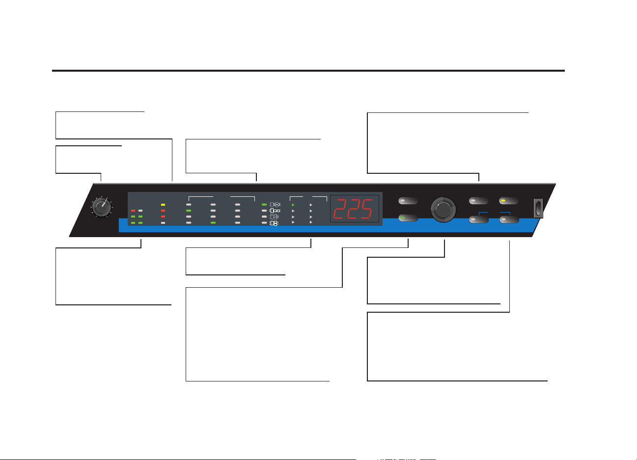
Input
Load
Edit
Compressor
Store
System
Bypass
Power
Tap/Cancel
MIDI
Learn
Threshold
- 3dB
- 10dB
- 20dB
Compressor
Chamber
Gate
Echo/Delay
Plate
Room
Flange
Rotry/Trmlo
Hall
Ambience
Chorus
Pitch/Detune
Mix
Adjust
EQ
Lvl/Bal
Ratio
Threshold
Attack
Release
- Clip
- 12dB
- 30dB
LEVEL COMPRESSOR EFFECTS ROUTING (DUAL) EDIT
L R
C
C
C
C
Input Knob
Sets the level of the
incoming signal.
Input LEVEL LEDs
Green = Presence of an input
signal for L & R channels.
Red = Indicates Input saturating
for that channel; or, the
internal processing is
saturated.
Store Button
Indicates Store is active. (When pressed with
Tap, activates MIDI learn.)
Tap Button
Flashes for Tempo-based programs. Press twice to set a
tempo. Hold to have input level determine tempo.
(When pressed with Store, activates MIDI learn.)
Adjust Knob
Multi-function knob to select effects and
routing, control edit functions, change
parameter values. Functions are
assignable by pressing Load, Edit, etc.
Compressor Button
When on, the red LED is lit and the 4 LEDs labeled
Compressor show the amount of gain reduction
being obtained.
Bypass Button
Mutes or bypasses the signal, depending on the setting
of the system Bypass parameter. Also accesses System
parameters when pressed for 2 seconds.
Edit Button/MIDI LED
Lights to indicate that the current program
has been altered from the original. When
blinking, there is MIDI activity. To return to
cueing new programs, press the Load
button.
EFFECTS and ROUTING LEDs
Indicate which effects are selected and,
for dual-effects programs, which routing
is selected.
EDIT Parameter Display
Indicates which parameter is
selected for editing.
COMPRESSOR LEDs
Show the amount of gain
reduction being obtained.
Load Button
Causes the cued program to load. Lights
to indicate that the program cued is
different from the program currently
running.
FRONT PANEL DETAILS AND USAGE
Page 16
1-3
Getting Started
MPX 200
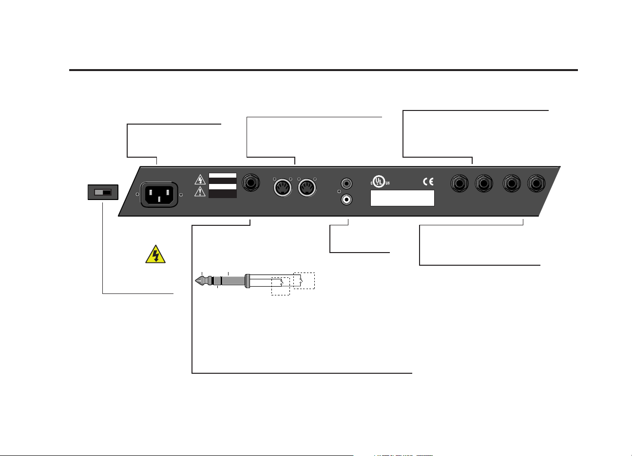
REAR PANEL DETAILS AND USAGE
Power
Uses a detachable IEC power
cable. Use the correct cable
for receptacles in your area.
MIDI IN and OUT/THRU
The MPX 200 is shipped with the System
parameter for MIDI OUT/THRU set to OUT.
To change this to a MIDI THRU port, change
the System parameter to THRU.
OUTPUT
L & R 1/4-inch Unbalanced Outputs. If no cable is
plugged into the L Output, the R Output provides
a mono signal of both channels. If no cable is
plugged into the R Output, the L Output can
drive a set of stereo headphones.
100-120/220-240V~
50 - 60Hz, 25W
Line Voltage Switch
Located on the side
of the unit.
IMPORTANT!
Be sure to select the
appropriate voltage
for your area to avoid
damage to the unit.
CAUTION
RISK OF ELECTRIC SHOCK
DO NOT OPEN
ATTENTION
RISQUE DE CHOC
ELECTRIQUE
NE PAS OUVRIR
FOOTSWITCH
TO REDUCE THE RISK OF FIRE OR
ELECTRIC SHOCK DO NOT EXPOSE
THIS UNIT TO RAIN OR MOISTURE
FOOTSWITCH
A momentary-contact footswitch.
Tip - Tempo
Ring - Bypass
Sleeve - Ground
Tip Sleeve
Ring
The footswitch jack requires a Tip/Ring/Sleeve 1/4-inch plug. The Tip
controls Tempo similar to the Tap button and the Ring controls Bypass
similar to the Bypass button. A handy mnemonic to remember is: “Tip
for Tempo; Ring for Reverb.” You cannot use an “unbalanced” Tip/
Sleeve plug for the footswitch because the MPX 200 will detect this
as if the Bypass button were being pressed.
Powering-up the MPX 200 with a Tip/Sleeve plug inserted into the
footswitch jack will cause it to enter Diagnostic Mode. If this occurs,
turn the MPX 200 off, remove the plug, and turn it on again.
T-TAP
R-BYP
S-GND
Tip
Ring
Sleeve
MIDI
IN OUTOUT / THRU
Tap
Bypass
44.1K S/PDIF
IN
This device complies with Part 15 of the FCC rules.
Operation is subject to the following two conditions:
(1) this device may not cause harmful interference; and
(2) this device must accept any interference received,
including interference that may cause undesired operation.
S/PDIF
Digital
Input and Output
LISTED
PROFESSIONAL
AUDIO EQUIPMENT
OUTPUT
8B25
LEFT
RIGHT
(PHONES)
(MONO)
INPUT
L & R 1/4-inch Unbalanced Inputs.
If no cable is plugged into the L Input,
the R Input feeds a mono signal to
both channels.
INPUT
LEFT RIGHT
(MONO)
Page 17
1-4
Getting Started
Lexicon, Inc.
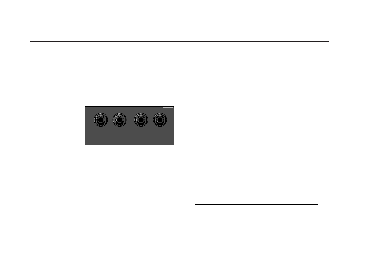
INPUT & OUTPUT
The Input and Output jacks on the MPX 200 are 1/4-inch
unbalanced sockets. If no plug is inserted into the Left
Input, the Right Input becomes a mono-signal – fed into
both Left and Right. The Inputs are Hi-Z and sensitive
enough to accommodate an electric guitar plugged
directly into the MPX 200.
If no plug is inserted
into the Right Output,
the Left Output
becomes a stereo
T/R/S output. It is also
capable of driving
headphones.
It is always good practice to route your audio cables
away from power cables.
SETTING AUDIO LEVELS
1. Start with Input set to 9:00 o’clock.
2. Set the instrument volume control to a nominal level.
Begin to play or send audio to the MPX 200. The
Level LEDs remain off during the loudest passages.
3. While still sending audio to the MPX 200, gradually turn up the Input control until the Clip LEDs show
red on only the loudest peaks.
4. Set the Mix control to “Dry.”
5. Adjust output to the desired level.
6. If the MPX 200 is using a console’s send and
returns, set the Mix control fully clockwise (100%
wet) and the system parameter Mix Mode to
Global (see page 3-4). If you are using an instrument amplifier, start with Mix set halfway up.
The Level LEDs are off when the incoming signal is low
(more than 30dB below overload.) The Clip LEDs light red
when the signal approaches overload (-1dB).
Acceptable signals will cause the Level LEDs to light green
almost continuously, with the Clip LEDs flashing red on
peaks.
Note:
As with any audio product, it is good practice to
first power on all outboard gear, then the mixer,
then any loudspeakers.
Input and Output Jacks
OUTPUT
INPUT
LEFT
(PHONES)
RIGHT
(MONO)
LEFT RIGHT
(MONO)
Page 18
2-1
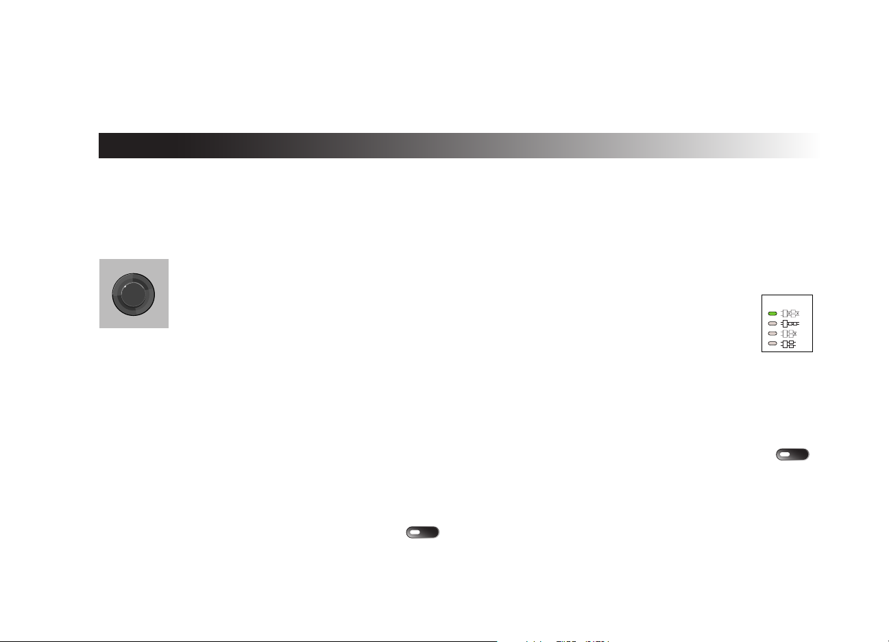
THE ADJUST KNOB
The Adjust knob is located on the right side of the front
panel and performs multiple functions. For example:
A. When the Load button is pressed,
the Adjust knob is used to select
the programs.
B. When the Edit button is pressed,
the Adjust knob is used to control
one of the Edit functions.
To reassign the Adjust knob for selecting Programs, press
the Load button.
Other functions are described throughout this manual.
SELECTING AND LOADING PROGRAMS
The MPX 200 contains 240 presets and storage for 64 User
Programs. To select a Preset or User Program as the
running program:
1. Press the Load button. (Omit this step if you are
already in Program Load mode.)
2. Turn the Adjust knob until your desired program
number appears on the display, or effects and
routing are indicated by the EFFECTS and ROUTING LEDs.
3. Press Load again to load your selected program.
The program can also be set to load automatically. (See Autoload on page 3-3 / item 14).
Your loaded program number is displayed in the
3-digit display. The LEDs for the selected
program will light to indicate which effects the
selected program contains. If the selected
program contains a dual effect, the appropriate
ROUTING LED will light.
The compressor will always be available in any program,
and is situated in front of any other effect for the
"wet" component signal path. If compression is
included in that program, the COMPRESSOR effect LED
lights even though the compressor can always be turned
on or off (using the Compressor button). Thus, the EFFECTS
display shows what would run if that program were
loaded.
2
Basic Operation
L
r
Load
ROUTING (DUA
C
C
C
C
Compresso
Page 19

2-2
Basic Operation
Lexicon, Inc.
CUEING PROGRAMS
For live performance or mixing in the studio, you may
want to “jump” from one program to another. The MPX
200 allows you to cue a program for loading.
1. Turn the Adjust knob to the Program you want to
load next (but do not press the Load button).
After 4 seconds the display and the EFFECTS and
ROUTING LEDs will revert to showing the currently
running program, but the Load button will remain
lit to indicate its armed status. To review the cued
program, rotate the Adjust knob one click to
redisplay its number and effects.
2. Press Load to load your cued program.
The Load button lights when a new program has been
selected for loading, indicating that the button is armed.
Pressing the Load button will then cause the selected program to load. (If the selected program has not been
changed or the running program has not been edited
since it was loaded, the LED will not be lit, indicating that
pressing this button will have no effect.)
EDITING PROGRAMS
The Adjust knob is used to control the EDIT functions. The
lighted LED indicates the selected parameter while the
display indicates the value of that parameter.
1. Press the Edit button to enter the Editing
mode. Each time you press the Edit button,
it selects the next parameter for you to edit.
2. Turn the Adjust knob to change the parameter.
An appropriate value for that control will be
displayed.
After changing a parameter value, the MPX 200
will wait 4 seconds and then "timeout" and revert
to displaying the active program number in the
display. You can tell that Edit mode is still active
because the current parameter LED is still lit.
Compressor, Mix, and Tempo parameters can be
set via System Parameters as either Global or
Program. When set as Program, a change to
these parameters is considered a “program edit”
and is reported with the activation of the Edit LED.
When set as Global, a change is not considered
an “edit.”
If you were previously operating a control and then
pressed Load, pressing Edit will return to the previous control. The Edit button lights when a parameter has been
changed and is different from its stored value.
Press the Load button to reassign the Adjust knob to select
Programs.
MIDI
Edit
Load
Page 20

2-3
Basic Operation
MPX 200
The Program Parameters
Mix Controls the proportion of processed (wet) to
unprocessed (dry) signals. The range is from 0
(dry) to 100% (wet).
Adjust Modifies various parameters of the current pro-
gram (The selection depends on the program
running. See Section 4 – Program Descriptions.)
The Adjust range is 0 -127, selected based on
external MIDI control having 128 steps.
EQ Controls the frequency content of the active
program, usually by affecting the output
HighCut filter or some other parameter appropriate to that program. EQ is expressed in hertz
(Hz) or kilohertz (KHz).
Lvl/Bal Sets the level of the Single effects and the bal-
ance of the Dual effects. In Single programs,
the range is 0-100% and represents the output
level of the effect. However, in the Dual programs, the Level/Balance range is -50 to 50
where at -50 you are listening only to the output
of the 1st effects block, at 0 you hear an equal
balance between the effects blocks, and at 50
you are listening only to the output of the 2nd
effects block. The current routing of the block is
indicated by the front panel ROUTING LED.
Page 21
2-4
Basic Operation
Lexicon, Inc.
TEMPO FEATURES
Tap
Tap allows delays and effects to be locked to the tempo
of your music. Whenever this Tempo feature is active in a
program, the green Tap LED flashes. To lock the delay or
effect to the tempo of your music, simply press Tap twice,
in time with the music, to set a tempo. The MPX 200 recognizes tempos from 40 to 400 bpm (beats per minute).
Audio TAP
In addition to entering a program tempo directly via the
Tap button, you can also use audio input such as two
drum hits or a vocal countoff to set the tempo of the MPX
200 delay times:
1. Press and hold the Tap button for 2 seconds.
(The optional dual footswitch input on the
back panel performs the same function as
the Tap button.) The display will read "Aud"
(Audio).
2. While holding down Tap, play two short notes in
rhythm, then release the Tap button. The MPX 200
automatically calculates the tempo from the
space between your two notes.
3. When you release Tap, the current bpm will show
on the digital display and the LED in the Tap button will light to indicate that tempo can now be
further adjusted from the front panel. Just turn the
Adjust knob to dial in a tempo (in bpm).
4. Press Tap to exit this mode.
For live performances this is an easy way to set delay rates
to follow your rhythm.
Global Tempo
Many factory presets are stored with their own tempo
rate. You can tap in a new tempo (and store your version
in a User location) or set the MPX 200 to globally recall the
last tempo used and apply it to every program (see
Section 3 - System Mode).
When you select Global Tempo from the MPX 200 System
mode, the last tempo used will be applied to all programs
with tempo-controlled parameters. (If a program is
tempo-controllable, the Tap button flashes when the program is loaded.)
Tap/Cancel
Page 22

2-5
Basic Operation
MPX 200
Setting Tempo via MIDI
When used in conjunction with the Learn feature, Tap can
be set remotely from any MIDI device. MIDI controllers,
such as the Lexicon MPX R1 Foot Controller, can be used
to send Continuous Controller messages or Program
Changes to the MPX 200. You can also send Continuous
Controller or Program Change messages from the controls
of many mixing consoles. The MPX 200 will learn these
messages and allow you to set tempo via MIDI. The MPX
200 can also receive and utilize MIDI Clock.
See Section 5 – MIDI Operation – for instructions on setting
MIDI controllers.
THE COMPRESSOR
The MPX 200 compressor is used in either of two ways:
1. for subtle reduction of volume changes so that
quieter passages in your program material can
be made louder.
2. as a limiter to prevent your volume from exceed-
ing a certain level.
For subtle volume reduction, use a lower ratio and set the
threshold low enough so that the program material is
above threshold much of the time. For severe limiting, a
high ratio (10:1) is necessary, but the threshold should be
kept high enough so that only the loudest peaks are compressed.
Attack controls how fast the compressor responds to volume increases. The best setting for Attack depends on the
frequency content of the program material. A fast attack
allows less sound to "leak through" before the compressor
reacts to sudden volume increases. However if the attack
time is shorter than the period of the predominant low frequency in the music, the compressor will react to the
music's waveform, rather than its volume envelope, resulting in various forms of distortion. If you hear this with low
frequency material, increase the Attack.
Page 23

2-6
Basic Operation
Lexicon, Inc.
Release time determines how fast the compressor
responds to volume reductions. With most music material,
the release time should be longer than the attack time.
This is especially true with instruments such as guitar or
piano which have their own natural slow volume decay
on sustained notes.
Compression can be overused! For most music material,
compression should be used in moderation so that the listener doesn't notice the result.
The Compressor Parameters
Rotate the Adjust knob to change the compressor parameter highlighted. An appropriate value for that control will
be displayed.
Successive presses of the Edit button will sequence
through the following compression parameters, then back
to the four program parameters.
Ratio Determines the compression ratio of the
compressor. Available values will be: Off, 2:1,
3:1, 5:1, and 10:1.
Threshold Determines the signal threshold below which
the compressor is inactive.
Attack Controls the attack time (in msec) of the
compressor.
Release Controls the release time (in msec) of the
compressor.
After changing a parameter’s value, the MPX 200 will wait
four seconds and then "timeout" and revert to displaying
the active program number in the digital display.
Page 24

2-7
Basic Operation
MPX 200
BYPASS
The Bypass button mutes the audio or bypasses
the current effect(s) when pressed. The exact
behavior depends on the setting of System Parameter #5
(See Bypass Mode, page 3-2). The choices are Dry ("dry"),
Mute ("qui" as in quiet), or Input Mute ("inp"). Dry means
that only dry audio is passed. Mute means that no audio
is passed. Input Mute means that both the dry audio and
the input to the current effect are muted, but the current
effect continues to run. If the current effect has any sustained sound (for example, the decay of a reverb or
echo), that sound continues through its normal decay.
When entering the Bypass mode, “byP” will show
in the display and the yellow LED in the Bypass
button will light.
STORING PROGRAMS
After editing a Preset, all the changes made to the Edit
and Compressor parameters can be stored in any of 64
user locations. To save a program:
1. Press Store.
The Store LED will light to indicate that the MPX
200 store function is armed, and the display will
read “U1” or the location of the first empty user
storage position.
The Cancel LED will also light to indicate that
you can exit without saving the current
program by pressing Tap/Cancel.
2. To store a program in a location other than the
one displayed, turn the Adjust knob to the desired
User location.
The Load button will light if the selected location
already contains a program. The LED will be off if
that location is empty.
3. Press Store again.
The Store button will flash rapidly while the store
operation is occurring and will turn off when store
is complete. The Edit and Load buttons will also
turn off, as the saved version becomes the current active program.
Caution:
If there is a program already stored in a selected
location, you will overwrite that program.
Bypass
Store
Tap/Cancel
Page 25

2-8
Basic Operation
Lexicon, Inc.
SELECTING AND LOADING
USER PROGRAMS
During Program selection, rotating the Adjust knob to
numbers higher than the presets selects the User
Programs, indicated by the letter “U.” To load a User
Program, select the User Program and press Load.
If a User Program is empty, the EFFECTS and ROUTING LEDs
will be off and pressing Load will have no function.
Page 26

3-1
The MPX 200 provides ultimate control via its System
parameters. The System Mode allows you to change the
behavior of the MPX 200 as well as access its internal MIDI
dumps & features.
To enter System Mode, press and hold Bypass for
approximately two seconds. The Bypass button
lights and the display flashes "SyS" to indicate
you are in System mode. The digital display will
then read "Out" (Output Level is the first system
parameter).
Note:
In System Mode, all other front panel controls are
disabled until you exit this mode. However, the
MPX 200 is still able to pass and process audio
while in this mode.
The adjustable parameters available in this mode are
shown in the “System Mode Parameters” chart on the
next page.
To select another system parameter, press Bypass. Each
press of the Bypass button will advance to the next available system parameter. A symbolic 3-character string will
be shown in the digital display to indicate the system
parameter selected. After selecting the last system
parameter, the next press of Bypass returns you
to "Out" level (this behavior is similar to that of the
Edit parameters).
To view the current setting of the parameter, click the
Adjust knob once. The display will show the current value.
To change a system parameter, rotate the Adjust knob further, either left or right. (In some instances, such as MIDI
dumps, the Store button lights. Press Store to execute this
MIDI dump. The digital display will indicate the current
state.)
3
System Mode
Compressor
Page 27

3-2
System Mode
Lexicon, Inc.
Note:
System parameters are automatically saved with
each change. Changes you make to these controls are applied immediately (except for Global
Compressor Mode) and remain in that state until
changed again.
To exit System Mode, press & hold Bypass again for
approximately two seconds. The display will
flash “Sto” to verify that any changes you made
have been stored.
Note:
The System Parameter Mix Mode is identified on
the 3-digit display as "d-p.” Some users have
wondered: "Why such a cryptic name? What
does it mean?" Think of "d-p" as short for "dryprocessed.” This name was chosen because a 7segment digit cannot display either "m" or "x,”
which would have been the logical choices.
Hence a name was chosen that would be distinctive from other System Parameter names.
SYSTEM MODE PARAMETERS
1. Output Level 0 dB - Off
2. Input Source Analog* or Digital
(S/PDIF)
3. Digital Dry or Processed*
Output
4. Global Mix Program* or Global
Mode
5. Bypass Mode Mute All/Quiet (qui),
Input Mute (inp), or
Bypass (dry)*
6. Program Mute or Bypass*
Load
7. Global Tempo Program*or
Mode (Tap) Global
8. Global Program* or
Compressor Mode Global
9. Patching Off or On*
* designates default value
Page 28

3-3
System Mode
MPX 200
10. MIDI Channel Off, Channels 1 -16,
All (Omni)
11. MIDI Pgm Off or On*
Change
12. MIDI Clock Off or On*
Receive
13. MIDI Out* or Thru
OUT/THRU
14. Autoload Off* or On
15. Dump
User Bank Press Store to execute
16. Dump Current
Program Press Store to execute
17. Dump
System Press Store to execute
18. Clear
User Bank Press Store to execute
19. Initialize
1. Output Level: This is the first parameter that you
will see when entering the System Mode. It adjusts
the overall output level of the MPX 200 from 0dB
(maximum) down to Off.
2. Input Source: Here you select either the Analog or
Digital (S/PDIF) input. If you select Digital In and
no digital signal is present, the MPX 200 will mute.
Note:
When the Input Source is set to Digital and the
MPX 200 is in either Load mode or Edit mode, the
display will show a message for four seconds
whenever it detects any change in the S/PDIF
input status. For example, if you remove the input
cable while it is connected and receiving a valid
44.1k S/PDIF signal, the display will show
"nod" for "no digital". Whenever it
re-acquires a digital signal, it will show
"dig".
* designates default value
continued on next page . . .
Page 29

3-4
System Mode
Lexicon, Inc.
3. Digital Output: For certain recording and monitor-
ing applications, or to use the MPX 200 as a standalone 24-bit converter, this parameter allows you
to choose to pass either dry audio or processed
audio out the S/PDIF digital output connector.
4. Global Mix Mode: Determines whether the current Mix setting will be applied to all programs
(Global) or whether program-specific Mix levels
are restored on each program load (Program). A
default Mix value is stored with each program.
These individual stored values will take effect
when a program is loaded if Global Mix is set to
Program. The Global mix setting will override the
individual stored settings if Global Mix is set to
Global.
5. Bypass Mode: Sets the Bypass button (or the
footswitch, or MIDI controller assigned to
Bypass) to mute the inputs to the current
effects; to mute the inputs and outputs; or to
bypass the processed audio (passing only
dry audio to the outputs).
6. Program Load: Determines whether the MPX 200
will mute completely or pass dry audio while
changing programs.
7. Global Tempo Mode: Determines whether the
current tempo of the MPX 200 will be applied to
all programs (Global), or whether program-specific tempos are restored on each program load
(Program). A default tempo is stored with each
program. These individual stored values will take
effect when a program is loaded if Global Tempo
is set to Program. The Global Tempo setting will
override the individual stored settings if Global
Tempo is set to Global.
8. Global Compressor Mode: Determines whether
the current compressor parameter settings of the
MPX 200 will be applied to all programs (Global),
or whether program-specific compressor parameters are restored on each program load
(Program). Changes you make to the four compressor parameters are stored with each program. These individual stored values will take
effect when a program is loaded if Global
Compressor Mode is set to Program. The Global
Compressor setting will override the individual
stored compressor parameter settings if set to
Global.
continued on next page . . .
Page 30

3-5
System Mode
MPX 200
Note:
Program Compressor Mode is not activated until
you load a new program after selecting Program.
9. Patching: Allows you to temporarily suspend (Off)
and restore (On) any Learned MIDI patches.
10. MIDI Channel: Allows selection of a MIDI channel
for all MPX 200 messages (Learned and Program
Changes). The choices are Off, Channels 1
through 16, or All Channels (OMNI mode).
11. MIDI Program Change: Determines whether or
not the MPX 200 will recognize MIDI Program
Change messages for loading programs.
12. MIDI Clock Receive: Determines whether or not
the MPX 200 will recognize MIDI Clock messages.
13. MIDI OUT/THRU: Sets the rear panel MIDI OUT/THRU
jack for either MIDI OUT or MIDI THRU functionality.
Note:
MIDI dumps can only be performed when this
parameter is set to MIDI OUT. ( See items 15-17)
14. AutoLoad: Determines whether the selected program loads automatically. If AutoLoad is set to
On, a new program selected with the Adjust knob
will be loaded automatically about 1/4-second
after the knob has stopped turning.
Note:
When any of the MIDI dumps are received by the
MPX 200 from an external device, they are automatically applied or stored.
continued on next page . . .
Page 31

3-6
System Mode
Lexicon, Inc.
15. Dump User Bank: Allows you to execute a MIDI
bulk dump that transmits the User programs for
storage to an external sequencer or computer.
Press Store to execute the dump. User Programs
are dumped in four groups of 16—beginning with
1, 17, 33, and 49. Rotate the Adjust knob to select
which group to dump.
16. Dump Current Program: Allows you to execute a
MIDI dump that transmits the current program for
storage to an external sequencer or computer.
Press Store to execute the dump.
17. Dump System: Allows you to execute a MIDI
dump that transmits all system parameters and
MIDI patches for storage to an external
sequencer or computer. Press Store to execute
the dump.
18. Clear User Bank: Erases the contents of all 64 User
programs in the User Bank. Press Store to
execute. The display will show “Clr”
briefly to verify that the User Bank has been
cleared.
Note:
You cannot clear the User Bank while you are running a User Program.
19. Initialize: Restores all adjustable parameters of
the MPX 200 back to its factory default state. This
includes all User programs, System parameters
and Learned patches. Press Store to execute. The
display will show “rSt” while this is taking
place. This requires about one minute to
complete.
Warning:
Both “Clear User Bank” and “Initialize” erase all
Programs stored in the User Bank.
Page 32

4-1
The 240 programs in the MPX 200 are designed to provide
a full array of high caliber ambience, reverb, delay, pitch
shift and other effects. While auditioning the programs, be
sure to vary the Adjust and EQ parameters.
The Adjust and EQ parameters have been carefully customized for each individual program. In many cases they
control several effect parameters simultaneously to provide simple control of a complicated editing process. For
example, in many Chamber and Room programs Adjust
controls the "liveness" of the space by changing decay,
EQ and early reflections, all at the same time. This parameter has a range of 0-127 to make it compatible with MIDI
control.
This section of this manual provides a general description
of each MPX 200 Bank along with tables that detail all of
the programs available in each Bank. This includes the
function of the Adjust parameter and the Tap button (for
programs that use tempo-controlled rate or delay times).
4
Program Descriptions
Bank Programs
Plate 1-9
Gate 10-19
Hall 20-29
Chamber 30-39
Ambience 40-49
Room 50-59
Tremolo 60-64
Rotary 65-69
Chorus 70-74
Flange 75-79
Detune 80-84
Pitch 85-89
Delay/Echo 90-104
Bank Programs
Compressor 105-109
Special FX 110-119
Flange - Delay 120-129
Pitch - Delay 130-139
Chorus - Delay 140-149
Delay - Reverb 150-159
Flange - Reverb 160-169
Pitch - Reverb 170-179
Chorus - Reverb 180-189
MonoSplitDly 190-204
MonoSplitRvb 205-224
Dual Mono 225-240
MPX 200 Programs
Page 33

4-2
Program Descriptions
Lexicon, Inc.
PLATE
Plate reverb was originally generated by a large, thin
sheet of metal suspended upright under tension on
springs. Transducers attached to the plate transmitted a
signal that made the plate vibrate — making any sounds
broadcast through it seem to be occurring in a large
open space.
The Plate programs synthesize the sound of metal plates
with high initial diffusion and a relatively bright, colored
sound. These programs are designed to be heard as part
of the music, mellowing and thickening the initial sound.
They are a popular choice for enhancing pop music, particularly percussion.
# Plate Programs Adjust Tap
1 Small Plate Liveness –
2 Medium Plate Liveness –
3 Large Plate Liveness Predelay
(1/32 Note)
4 Tap PreDelay MidRT Predelay
(1/32 Note)
5 Tape Slap ips (7.5/15) –
6 Rich Plate MidRT Predelay
(1/32 Note)
7 Large&Bright MidRT Predelay
(1/32 Note)
8 Vocal Plate Liveness Echo
9 Drum Plate Liveness –
Page 34

4-3
Program Descriptions
MPX 200
GATE
Gated reverbs were originally created by feeding a
reverb, such as a metal plate, through an analog gate
device. The decay time was set to instant, and the hold
time varied the duration of the sound.
The Gate programs provide a fairly constant sound with
no decay until the reverb is cut off abruptly. These programs work well on percussion – particularly on snare and
toms – but make sure to experiment with other sound
sources as well.
Note:
Audio is muted briefly when Time is altered with
Adjust.
# Gate Programs Adjust Tap
10 StraightGate Time –
11 Slope Down Time –
12 Drum Gate Slope Predelay
(1/32 Note)
13 140ms TapPre Slope Predelay
(1/32 Note)
14 240ms TapPre Slope Predelay
(1/32 Note)
15 340ms TapPre Slope Predelay
(1/32 Note)
16 440ms TapPre Slope Predelay
(1/32 Note)
17 540ms TapPre Slope Predelay
(1/32 Note)
18 Inverse Time –
19 Dark Inverse Time –
Page 35

4-4
Program Descriptions
Lexicon, Inc.
HALL
Lexicon's Hall programs recreate the acoustics of actual
places—from grand reverberant enclosures to small concert halls.
The clean reverberation of the Hall programs is designed
to add spaciousness, while leaving the source material
unchanged. In addition to general instrumental and
vocal applications, the Hall programs are a good choice
for giving separately recorded tracks the sense of belonging to the same performance.
# Hall Programs Adjust Tap
20 Small Hall MidRT –
21 Medium Hall MidRT –
22 Large Hall MidRT –
23 Small Church MidRT –
24 Large Church MidRT –
25 Jazz Hall MidRT –
26 Dance Hall MidRT –
27 Synth Hall MidRT –
28 Concert Hall MidRT –
29 Gothic Hall MidRT –
Page 36

4-5
Program Descriptions
MPX 200
CHAMBER
Historically, recording studio chambers were oddly
shaped rooms with a loudspeaker and set of microphones
to pick up the ambience in various parts of the room.
The stereo Chamber programs produce even, relatively
dimensionless reverberation, with little change in color as
the sound decays. The initial diffusion is similar to the Hall
programs, but the sense of space and size is much less
obvious. This characteristic, along with the low color of the
decay tail, makes these programs useful on a wide range
of material. They are especially useful on spoken voice,
giving a noticeable increase in loudness with very low
color.
# Chamber Programs Adjust Tap
30 Brick Wall MidRT –
31 Basement MidRT –
32 Live Concert Liveness Echo Delay
33 Drum Chamber MidRT –
34 Moves on... Liveness –
35 Live Chamber Liveness –
36 VocalChambr1 Liveness Echo Delay
37 VocalChambr2 Liveness Echo Delay
38 Wide Chamber Liveness –
39 PCM60: Large MidRT –
Page 37

4-6
Program Descriptions
Lexicon, Inc.
AMBIENCE
Ambience gives warmth, spaciousness and depth to a
performance without coloring the direct sound, and is
commonly used to add a room sound to recorded music
or speech. In music recording, Ambience can realistically
add distance to closed-mike signal.
The Ambience programs simulate reflections from room
surfaces with random reflections, a gradual decay of
overall level, and a gradual narrowing of the bandwidth.
In these programs, the Mix control adds depth–emulating
the movement of a coincident pair of microphones away
from the sound source into the room.
# Ambience Programs Adjust Tap
40 Announcer Decay –
41 VerySmallAmb Decay –
42 SmallAmb Decay –
43 MidSizeAmb Decay –
44 Studio "D" Decay –
45 Bright Amb Decay –
46 Dark Amb Decay –
47 Marble Foyer Decay –
48 Smooth Amb Decay –
49 Guitar Amb Decay –
Page 38

4-7
Program Descriptions
MPX 200
ROOM
Room programs emulate actual rooms where there is a
more apparent sense of being in a small, live place.
The Room programs are very useful on drums and percussion and can also be applied to electric guitar tracks.
# Room Programs Adjust Tap
50 Bedroom Walls –
51 Tiled Room LF Boost –
52 Studio "C" MidRT –
53 Small Room Liveness –
54 Studio "B" MidRT –
55 Rehearsal Room MidRT –
56 Studio "A" MidRT –
57 Large Room MidRT –
58 Fat Space MidRT –
59 Chunky Space MidRT –
Page 39

4-8
Program Descriptions
Lexicon, Inc.
TREMOLO
Tremolo is a rhythmic change in loudness, commonly
employed as an expressive technique by vocalists and
wind instrument players. It is also one of the oldest electronic effects — frequently used with electric guitar, electric piano and, occasionallly, vocals. Different tremolo
effects are largely determined by the rate and waveform
shape of the loudness change (fast or slow, smooth or
sharp). If the effect is used in a stereo mix, the left and
right can be synchronized in a variety of ways to produce
dramatic side-to-side motion.
The Tremolo programs offer a variety of tremolo shapes
(square, sawtooth, triangle, sine and rectified sine). The
synchronization of the left and right sides can be adjusted
to produce mono and stereo effects. As the tremolo rates
are set with Tap, it is easy to match the tempo of the
music. The Adjust knob (phase) lets you set left and right
channel waveforms out-of-phase, resulting in a panning
motion.
All of these programs should be used with Mix set to fully
wet. By adding more dry to the wet/dry mix, Mix effectively sets the depth of the Tremolo. Take care to make the
rate work with the tempo of the music, as Tremolo is essentially a rhythmic effect .
# Tremolo Programs Adjust Tap
60 RectSineTap Phase Rate
(1/8 Note)
61 Square Tap Phase Rate
(1/8 Note)
62 Sine Tap Trpl Phase Rate
(1/8 Note)
63 Triangle Phase Rate
(1/8 Note)
64 Sawtooth Phase Rate
(1/8 Note)
Page 40

4-9
Program Descriptions
MPX 200
ROTARY
Rotary speaker cabinets were originally designed to provide a majestic vibrato/choir effect for electronic theater
and church organs. The most well known rotary speaker is
the Leslie™ Model 122, which has two counter-rotating
elements: a high frequency horn and a low frequency
rotor with slow and fast speeds. As the spinning elements
change speed, the sound generated is truly magical. The
swirling, spacious effect is hard to describe, but is instantly
recognizable.
The rotary effect is a detailed simulation of a Leslie-style
cabinet. The input signal is split into high and low frequency bands. The rotation effect is created by a synchronized
combination of pitch shifting, tremolo and panning. Like
the physical model, the high (horn) and low (drum) frequencies are “spun” in opposite directions. Horn and
drum speeds are independent, and are designed with
acceleration and deceleration characteristics to simulate
the inertia of the original mechanical elements.
A virtual requirement for any organ sound, the rotary programs also sound great with guitar and electric piano
rhythm parts. In fact, they are great alternatives to chorus
and tremolo effects for any sound source.
All of these programs should be used with Mix set to fully
Wet to achieve the full effect.
# Rotary Programs Adjust Tap
65 Rot SlowFast Switch –
66 Rot Slow Resnce –
67 Rot SpeedAdj Speed –
68 Rot TapRate1 Balance Rate
69 Rot TapRate2 Resnce Rate
Page 41

4-10
Program Descriptions
Lexicon, Inc.
CHORUS
Chorus effects multiply the original audio source to create
a lush, full sound. Traditionally used to fatten up tracks and
to add body to guitar without coloring the original tone,
chorus effects are also often used in combination with
echoes, plates and other reverb effects.
The stereo Chorus programs use six independently randomized delay voices panned across the stereo field.
These programs, inherited from Lexicon's PCM 80, generate a rich, airy effect that can simulate the sound of multiple sources from a single source. These programs are
stunning on acoustic or clean electric guitar.
All of these programs should be used with Mix set to fully
Wet to achieve the full richness of the 6-voice chorus.
# Chorus Programs Adjust Tap
70 Chorus1 Resnce –
71 Chorus2 Resnce –
72 Chorus3 Diffusn –
73 Slap Chorus1 Diffusn –
74 Slap Chorus2 Depth –
FLANGE
Flanging effects were originally created by simultaneously recording and playing back two identical programs on
two tape recorders, then using hand pressure against the
flange of the tape reels to slow down first one machine,
then the other. The result was a series of changing phase
cancellations and reinforcements, with a characteristic
swishing, tunneling and fading sound.
The MPX 200 stereo Flanger has two 2-Tap delays — one
per channel. The first tap is fixed, and the second sweeps
past it. Mixing the two delay taps together creates the
flanging effect.
All of these programs should be used with Mix set to fully
Wet to achieve the full flange effect.
# Flange Programs Adjust Tap
75 Flng Lite Speed —
76 Flng Lite180 Resnce —
77 Flng Med180 Speed —
78 Flng Deep Resnce —
79 Flng Deep180 Resnce —
Page 42

4-11
Program Descriptions
MPX 200
DETUNE
Detune effects add a delayed/pitch-shifted version of the
original source — thickening up the sound. They can be
particularly effective when used to simulate double-tracking. They are also great alternatives to chorus effects,
adding the richness of a chorus without the audible
sweep caused by the chorus rate.
The 4-voice stereo Detune programs have one pair of
voices per channel. As more detune amount is applied
(with Adjust), the pair grow more out of tune, providing a
lush sound without the need for mixing in a dry signal.
All of these programs should be used with Mix set to fully
Wet to achieve the full effect.
# Detune Programs Adjust Tap
80 Detune Mild Dtuning –
81 Detune Med&Warm Dtuning –
82 Detune Heavy Dtuning –
83 Det Xtreme Dtuning –
84 Pitch Detune Dtuning –
PITCH
Altering the pitch of a sound allows a variety of effects,
from subtle detuning to the creation of harmonies and
chords.
The stereo polyphonic Pitch programs allow complete
program material or monophonic sources to be shifted
from two octaves down through one octave up.
For pitch correction, use these programs with Mix set to
fully Wet. For harmonization, use the desired amount of
wet/dry Mix.
# Pitch Programs Adjust Tap
85 Pch Chrmatic Pitch –
86 Pitch Fine Pitch –
87 Pch 4th-5ths Pitch –
88 Pch PowerInV Pitch –
89 Vocal Chorus Depth –
Page 43

4-12
Program Descriptions
Lexicon, Inc.
DELAY AND ECHO
Delays and echoes are effects that repeat a sound a
short time after it first occurs. The simplest (and oldest)
delay effect is tape slap — a single repeat about 100ms
after the original sound. (It was often used on Elvis
Presley’s voice and rockabilly guitar tracks.) Tape slap
becomes tape echo when the output of the tape is fed
back into the input (feedback), turning a single repeat
into a series of repeats — each a little softer and a little
darker than the last. This darkening of each repeat is characteristic of the analog tape recording process. Digital
delays do not have this characteristic–each repeat has
the same exact timbre and the only difference from
repeat to repeat is in loudness.
Digital delay and tape echo are both useful, but they are
different. Tape echo is warmer and allows the original
sound to stand out more, while digital delay can present
a “perfect” copy of the original sound.
The Delay and Echo variations include mono (up to 5.5
seconds), stereo (up to 2.7 seconds), and 6-voice multitap
effects. Each of the programs can be used for digital
delay or tape echo effects. When the Adjust parameter is
set to a value between 63 and 0, tape echo effects are
produced. (Each repeat is darker and softer.) When the
Adjust parameter is set to a value between 64 and 127,
digital delay effects are produced. (Each repeat is the
same timbre, but softer.)
In programs 90-97, Adjust also sets the amount of feedback — with an increasing number of repeats as the
parameter value is increased. Delay time is set with Tap.
Each program is preset with a different useful rhythm.
In Variations 98-104, the amount of feedback is preset and
Adjust determines Delay time.
When using any type of delay or echo effects with music,
always pay attention to the way the repeats fall rhythmically to the beat. The most effective delay and echo patterns are those that lock in with the tempo of the tune.
Page 44

4-13
Program Descriptions
MPX 200
Delay,Echo
# Programs Adjust Tap
90 Dly Mono Tap Feedbk Delay Time
91 DlyStereo Tap Feedbk Delay Time
92 Dly ShuflTap Feedbk Delay Time
93 Dly Dot8 Tap Feedbk Delay Time
94 Dly 8+3plTap Feedbk Delay Time
95 Dly Pong Tap Feedbk Delay Time
96 Dly XfbkTap1 Feedbk Delay Time
97 Dly XfbkTap2 Feedbk Delay Time
98 Dly Mono Time: 0-5.5sec –
99 Dly Stereo Time: 0-2.7sec –
100 Dly TapeSlap Time: 3 3/4 to 30ips –
101 Multi Bounce Time: 0-100ms –
102 MultiInverse Time: 0-400ms –
103 Multi Linear Time: 0-400ms –
104 Multi Pong Time: 0-150ms + Fbk –
Page 45

4-14
Program Descriptions
Lexicon, Inc.
COMPRESSOR
The compressor in the MPX 200 is a stand-alone control
that modulates the level feeding the other active
effect(s). It has no effect on the dry signal coming out of
the Mix control (or the Bypass signal when Bypass Mode is
set to Dry). Compression on a dry signal is obtained by
using a Delay/Echo algorithm with delay times set to 0.
Thus, the Mix control must be set to 100% for this to work
properly (this is the default setting when Global Mix Mode
is set to Program).
Programs 107, 108 and 109 use a Parallel Reverb-Delay
algorithm to obtain compression on both a dry and wet
signal. To use this program, observe the following:
• Keep the MPX 200 Mix set to 100% (the default setting when Program Load is set to Program). The
dry signal will be obtained as a compressed
"delayed" echo with the delay time set to 0.
• Adjust the Reverb level by changing the Balance
parameter between full left (0%) and about 40%.
(Typical values should be between 5% and 10%.)
Compressor
# Programs Adjust Tap
105 3:1 Compression Gain Make-up -
106 10:1 Compression Gain Make-up -
107 Small Hall / Decay Pre-Delay
Compression (1/32 note)
108 Medium Hall / Decay Pre-Delay
Compression (1/32 note)
109 Large Hall / Decay Pre-Delay
Compression (1/32 note)
Page 46

4-15
Program Descriptions
MPX 200
SPECIAL FX
# Delay, Echo Presets Adjust Tap
110 Infinite Reverb Bass X-Over Frequency Echo
111 The Abyss ± Pitch Bend –
112 Jet Flange Tone Rate (Whole Note)
113 Chorus Verb Decay –
114 Rotary Delay Dly/Echo Time: 0-150ms+Fbk Rate (1/4 Note)
115 LowRumble Decay Time –
116 Echoes:Beats Echoes per Beat Delay Time
117 Stereo Stage * See page 4-16
118 Dream Sequence ± Shift Amount –
119 Infinite Delay Echo Feedback Delay Time
Page 47

4-16
Program Descriptions
Lexicon, Inc.
* PRESET 117
This preset supplies reverb while preserving stereo imaging
in a live stage setup. Stereo imaging is preserved via time
delay rather than conventional L/R panning so that a
proper channel mix is maintained in both L and R speakers. To use this program, observe the following:
• Use the MPX 200 in-line between mixer and house
amps, not as an effect that is mixed back into the
main L and R signals.
• On your mixer, pan the input channel for each
musician fully to that musician’s side of the stage.
• Keep Mix set to 50% (the default setting when
Program Load is set to Program).
• Adjust your Reverb level by changing the
Balance parameter between full left (-50) and
about -10. (Typical values should be between -45
and -40.)
• Set "Width" for the distance between the speakers
at each side of the stage. The program loads with
an assumed width of approximately 20 ft. The
available range via the Adjust knob is 10-50 ft.
These values assume that most audience members are seated within 30 degrees to either side of
the stage centerline. If many audience members
are seated further to the sides of the stage the
Adjust setting can be increased, but otherwise it
should be kept as low as possible.
Page 48

4-17
Program Descriptions
MPX 200
ABOUT THE DUAL PROGRAMS
The Dual programs combine either a Delay or Reverb
algorithm with a Flange, Pitch or Chorus, in addition to a
delay/reverb combination. The Effects Lvl/Bal parameter
controls the relative balance of each effect in the combination.
The Dual programs use four routing configurations: Dual
Stereo (Parallel), Cascade, Mono Split and Dual Mono.
Bank 14 (Special FX) contains programs which use a variety of routing configurations. The remaining Banks (15-23)
are organized as follows:
Banks 15-21 have the first six programs in each Bank set up
in the Parallel configuration–two stereo programs placed
side-by-side so that they receive and output stereo audio
from both left and right channels. The last four programs
in each Bank are set up in the Cascade
configuration–two stereo programs, one placed after the
other. For example, in Flange-Delay, Flange passes its
stereo signal to the Delay.
Banks 22 and 23 are set up in the Mono Split configuration which is similar to Parallel, but here, one effect
(Flange) receives audio from the left input and the other
effect (Delay) receives audio from the right input. Both
effects then output stereo audio.
Because Dual Mono programs are usually used differently, they are all grouped in the last preset Bank (24). In
these programs, one program (Flange) appears on the
left channel only and the other program (Delay) appears
on the right channel only.
Generally, the Effects Lvl/Bal parameter controls the balance of the two effects in each dual program. In the cascade variations, rather than simply controlling balance,
the Adjust knob varies the amount of the first effect or dry
signal which is fed into the second effect.
R
Dual Stereo (Parallel) Cascade Mono Split Dual Mono
Variations 1-6 Variations 7-10 Variations 11-14 Variations 15-16
L
AA
BB
L
R
L
R
AA
L
BB
R
L
R
AA
BB
L
R
L
R
L
AA
R
BB
Page 49

4-18
Program Descriptions
Lexicon, Inc.
FLANGE-DELAY
# Flange-Delay Presets Adjust Tap Routing
120 Flng Tap Feedbk Delay Time (1/4 Note) Parallel
121 Flng .8Tap Feedbk Dotted 1/8 Note Parallel
122 Flng 3plTap Feedbk 1/8 Note Triplet Parallel
123 Flng PongTap Feedbk Delay Time (1/4 Note) Parallel
124 Flng Xfeed Time: 0-150ms — Parallel
125 Flng Bounce Time: 0-200ms, Feedbk — Parallel
126 Flng>Tap Feedbk Delay Time (1/4 Note) Cascade
127 Flng>Fbk Time: 0-150ms, Feedbk — Cascade
128 Flng>Pong Feedbk Delay Time (1/4 Note) Cascade
129 Flng>Bnce Time: 0-200ms, Feedbk — Cascade
Parallel Cascade
L
R
FlangeFlange
DelayDelay
L
L
R
FlangeFlange DelayDelay
L
R
R
Page 50

4-19
Program Descriptions
MPX 200
PITCH-DELAY
# Pitch-Delay Presets Adjust Tap Routing
130 5th Tap Pitch Delay Time Parallel
131 8ve 3pTap Pitch Delay Time Parallel
132 8ve 8+3plTap Pitch Delay Time Parallel
133 3rd4thPong Pitch Delay Time Parallel
134 4th5th Xfeed Pitch Delay Time Parallel
135 5th6th Xfeed Pitch Delay Time Parallel
136 8ve> Xfeed Pitch Delay Time Cascade
137 5th>Xfeed Pitch Delay Time Cascade
138 MajMin>Fbk Pitch Delay Time Cascade
139 StepUp>Tap Pitch Delay Time Cascade
Parallel Cascade
L
R
PitchPitch
DelayDelay
L
L
R
R
PitchPitch DelayDelay
L
R
Page 51

4-20
Program Descriptions
Lexicon, Inc.
CHORUS-DELAY
# Chorus-Delay Presets Adjust Tap Routing
140 Chor Tap Feedbk Delay Time Parallel
141 Chor 8Tap Feedbk Delay Time Parallel
142 Chor 8+3pl Feedbk Delay Time Parallel
143 Chor Pong Feedbk Delay Time Parallel
144 Chor Repeat Time – Parallel
145 Chor Bounce Time – Parallel
146 Chor>Tap Feedbk Delay Time Cascade
147 Chor>Repeat Time — Cascade
148 Chor>Pong Feedbk Delay Time Cascade
149 Chor>Bnce Time – Cascade
Parallel Cascade
L
R
Chorus
DelayDelay
L
L
R
ChorusChorus DelayDelay
L
R
R
Page 52

4-21
Program Descriptions
MPX 200
DELAY-REVERB
# Delay-Reverb Presets Adjust Tap Routing
150 Tap Small MidRT Delay Time Parallel
151 3plTapMidSz MidRT Delay Time Parallel
152 8+3pl Large MidRT Delay Time Parallel
153 Pong Small MidRT Delay Time Parallel
154 Xfeed MidSz MidRT Delay Time Parallel
155 Xfeed Large MidRT Delay Time Parallel
156 Tap > Room Liveness Delay Time Cascade
157 8+3pl> Large MidRT Delay Time Cascade
158 Xfeed > Room Liveness Delay Time Cascade
159 Xfeed> Large MidRT Delay Time Cascade
Parallel Cascade
L
R
DelayDelay
ReverbReverb
L
LL
RR
R
DelayDelay ReverbReverb
Page 53

4-22
Program Descriptions
Lexicon, Inc.
FLANGE-REVERB
# Flange-Reverb Presets Adjust Tap Routing
160 LiteFl Small MidRT Speed (Whole Note) Parallel
161 LiteFl MidSz MidRT Speed (Whole Note) Parallel
162 LiteFl Large MidRT – Parallel
163 Deep Fl Small MidRT – Parallel
164 Deep Fl MidSz MidRT – Parallel
165 Deep Fl Large MidRT – Parallel
166 LiteFl > Small MidRT Speed (Whole Note) Cascade
167 LiteFl > Room Liveness Speed (Whole Note) Cascade
168 Deep Fl>Large MidRT – Cascade
169 Deep Fl>Room Liveness – Cascade
Parallel Cascade
L
R
FlangeFlange
ReverbReverb
L
L
R
R
FlangeFlange ReverbReverb
L
R
Page 54

4-23
Program Descriptions
MPX 200
PITCH-REVERB
# Pitch-Reverb Presets Adjust Tap Routing
170 3rd4th Room Pitch PreDelay (1/32 Note) Parallel
171 4th5th Room Pitch PreDelay (1/32 Note) Parallel
172 5th6th Room Pitch PreDelay (1/32 Note) Parallel
173 8ve MidSiz Pitch PreDelay (1/32 Note) Parallel
174 Power MidSiz Pitch PreDelay (1/32 Note) Parallel
175 Detune Room Dtuning PreDelay (1/32 Note) Parallel
176 Fine> Small Pitch PreDelay (1/32 Note) Cascade
177 Power>Large MidRT PreDelay (1/32 Note) Cascade
178 4th > MidSiz MidRT PreDelay (1/32 Note) Cascade
179 8ve> MidSiz MidRT PreDelay (1/32 Note) Cascade
Parallel Cascade
L
R
PitchPitch
ReverbReverb
L
L
R
R
PitchPitch ReverbReverb
L
R
Page 55

4-24
Program Descriptions
Lexicon, Inc.
CHORUS-REVERB
# Chorus-Reverb Presets Adjust Tap Routing
180 Chor1 Small MidRT – Parallel
181 Chor1 MidSiz MidRT – Parallel
182 Chor1 Large MidRT – Parallel
183 Chor2 Small MidRT – Parallel
184 Chor2 MidSiz MidRT – Parallel
185 Chor2 Large MidRT – Parallel
186 Chor1 > Room Liveness – Cascade
187 Chor2 > Room Liveness – Cascade
188 Chor3 > Room Liveness – Cascade
189 Chor1 > Small MidRT – Cascade
Parallel Cascade
L
R
ChorusChorus
ReverbReverb
L
L
R
ChorusChorus ReverbReverb
L
R
R
Page 56

4-25
Program Descriptions
MPX 200
MONO SPLIT DELAY
# MonoSplitDly Presets Adjust Tap Routing
190 Flng Tap Feedbk 1/4 Note Parallel
191 Flng Pong Feedbk 1/4 Note Parallel
192 Flng Xfeed Time – Parallel
193 Flng Bnce Time – Parallel
194 Deep Fl Dly Time – Parallel
195 5th Tap Pitch Delay Time Parallel
196 8ve 3plTap Pitch Delay Time Parallel
197 4th5th Xfeed Pitch Delay Time Parallel
198 5th6th Xfeed Pitch Delay Time Parallel
199 PchFine Tap Pitch Delay Time Parallel
200 Chor Tap Feedbk Delay Time Parallel
201 Chor Pong Feedbk Delay Time Parallel
202 Chor Xfeed Time – Parallel
203 Chor Bnce Time – Parallel
204 Chor Inverse Time – Parallel
Page 57

4-26
Program Descriptions
Lexicon, Inc.
MONO SPLIT REVERB
# MonoSplitRvb Programs Adjust Tap Routing
205 TAP MIDSIZ MidRT Delay Time
206 PONG LARGE MidRT Delay Time
207 BNCE MIDSZ MidRT Delay Time
208 XFEED SMALL MidRT Delay Time
209 XFEED MIDSIZ MidRT Delay Time
210 LITEFL MIDSZ MidRT Speed
211 LITEFL LARGE MidRT –
212 DEEPFL SMALL MidRT –
213 DEEPFL MIDSZ MidRT –
214 DEEPFL ROOM Liveness –
215 4TH5TH ROOM Pitch PreDelay 1/32
216 5TH6TH ROOM Pitch PreDelay 1/32
Continued on next page . . .
Page 58

4-27
Program Descriptions
MPX 200
Mono Split Reverb(cont.)
# MonoSplitRvb Programs Adjust Tap Routing
217 4THS LARGE MidRT –
218 8VE MIDSZ MidRT –
219 PCHFIN MIDSZ Pitch –
220 CHOR1 SMALL MidRT –
221 CHOR1 LARGE MidRT –
222 CHOR2 MIDSIZ MidRT –
223 CHOR2 LARGE MidRT –
224 CHOR3 MIDSIZ MidRT –
Page 59

4-28
Program Descriptions
Lexicon, Inc.
DUAL MONO
# Dual Mono Programs Adjust Tap
225 Tap Small MidRT Delay Time
226 Tap MidSz MidRT Delay Time
227 Tap Large MidRT Delay Time
228 Tap Room Liveness Delay Time
229 DeepFl Tap Feedbk Speed (1/4 Note)
230 DeepFl Dot 8 Feedbk Speed (dotted 1/4 Note)
231 8ves Tap Pitch Delay Time
232 8ves 3pl Pitch Delay Time
233 Chor2 Tap Feedbk Delay Time
234 Chor2 Dot8 Feedbk Delay Time
235 LiteFl Large MidRT Speed
236 DeepFl Large MidRT Speed
237 8ves MidSz MidRT PreDelay 1/32
238 4ths Large MidRT PreDelay 1/32
239 Chor1 Room Liveness --
240 Chor2 Room Liveness --
Page 60

5-1
MPX 200 MIDI BEHAVIOR
The MPX 200 "learns" Program Change and Continuous
Controllers in its Learn Mode. Learned patches are supported for the front panel Mix, Adjust, EQ and Lvl/Bal
parameters, as well as the front panel Bypass, Tap, and
the four Compressor parameters.
• The Bypass, Tap and Compressor buttons can also
be patched to Program Change.
• Program Change messages can also be used to
load programs.
• Program Change messages 0-99 are reserved for
executing program loads.
ASSIGNING A MIDI CHANNEL
FOR PROGRAM LOAD
There is one MIDI channel for all MIDI messages. Values are
“Off,” Channels 1 through 16, or “All” Channels (OMNI
mode). Its default value is Channel 1. See page 3-5 for
additional information.
MIDI BANK SELECT AND PROGRAM
CHANGE MESSAGES
MIDI Bank Select messages can be sent to the MPX 200
via Continuous Controller 32. Bank 0 contains
programs 1-99; bank 1 contains programs 100-199; bank 2
contains programs 200-240; and bank 3 serves as the User
Bank. Bank selection is also accomplished when a
program is cued up with the Adjust knob.
A MIDI Program Change message causes the selected
program to load from the currently selected bank, provided the selected program exists and MIDI Program
Change has been enabled with System Parameters. For
example, a Bank Select value of 1 followed by a Program
Change value of 57 will cause the MPX 200 to load program 157. A Bank Select value of 2 followed by a
Program Change value of 57 will cause the MPX 200 to do
nothing because there is no program 257. A Bank Select
value of 0 followed by a Program Change value of 0 will
cause the MPX 200 to do nothing because there is no program 0. Likewise, a Program Change message requesting
an empty location in the User Bank will be ignored.
5
MIDI Operation
Page 61
5-2
MIDI Operation
Lexicon, Inc.
LEARNING OTHER MIDI PATCHES
The MPX 200 recognizes Pitch Bend, AfterTouch, and MIDI
Continuous Controllers 1-31 and 33-119–in addition to
Program Change messages–to manipulate the audio
controls. To Learn a Continuous Controller or other MIDI
message:
1. Press Store and Tap simultaneously to enter Learn
Mode. The Store and Tap buttons light steadily to
indicate Learn Mode is active and the
display shows “lrn.”
2. Press the desired button (for example, Tap or
Bypass) or the Edit button to choose the desired
editable parameter.
3. Send a Program Change message or move the
MIDI controller through its full range. To use only a
fraction of the controller range, limit your movement to the desired range. The Edit LED will flash
to indicate incoming MIDI activity.
4. Press Store to commit to the assignment. The Store
LED will flash rapidly and the display
shows “Sto.”
To assign another front panel control to a MIDI
controller or Program Change message, repeat
steps 2 - 4.
5. Press Store and Tap simultaneously to exit. The
Store button will flash rapidly to indicate that
you are leaving Learn Mode.
Note:
When a MIDI controller is assigned to Tap, moving
it through the mid-point of its Learned range will
execute a "press" of the front panel button. When
a MIDI controller is assigned to Bypass or
Compressor On/Off, moving above or below its
mid-point will toggle the control on or off.
To aid MIDI controllers (such as some foot controllers)
which do not allow sending “single-button-repeated”
Program Change messages, the MPX 200 recognizes the
next highest Program Change along with every Program
Change message it learns for Bypass and/or Tap. For
example, if you Learn Program Change 120 as the source
for Bypass, Program Change 121 will also control Bypass
functions. To avoid conflicting Bypass and Tap
Page 62

5-3
MIDI Operation
MPX 200
assignments, leave a space between the two buttons’
assignments. For example, if you learn Program Change
120 for Bypass, remember that 121 will also be learned, so
you will have to jump to Program Change 122 (and 123)
for Tap.
CLEARING A LEARNED ASSIGNMENT
1. Simultaneously press Store and Tap to enter Learn
Mode. (The Store and Tap buttons light steadily to
indicate Learn Mode is active and the display
shows “lrn.”)
2. Select the front panel control that you want to
clear (for example, Mix, Lvl/Bal, Adjust, Bypass).
3. Press Store to clear the assignment. The
Store button will flash rapidly and the display will show “Clr.”
To clear another front panel assignment, repeat steps 2
and 3.
4. Simultaneously press Store and Tap to exit. The
Store button will flash rapidly if you have changed
any assignments.
LEARNABLE FRONT PANEL CONTROLS AND
ASSIGNABLE MIDI SOURCES
MIDI MIDI Defaults:
Front Panel Controllers Pgm Change Continuous
Control 1-31, 33-119 100-127 Controller #
Mix Yes No 1
Adjust Yes No 2
EQ Yes No 3
Effects Lvl/Bal Yes No 4
Ratio Yes No 5
Threshold Yes No 6
Attack Yes No 7
Release Yes No 8
Bypass Yes Yes 18
Tap Yes Yes 17
Compressor Yes Yes 16
(On/Off)
Page 63

5-4
MIDI Operation
Lexicon, Inc.
MIDI CLOCK
The MPX 200 recognizes MIDI Clock messages and applies
the tempo (40-400 bpm) to any program which utilizes the
Tap-Tempo feature. Connect a MIDI device which outputs
MIDI Clock (such as the MPX R1 foot controller or a MIDI
sequencer) to the MPX 200 MIDI IN jack to have the
MPX 200 automatically recognize and begin to process
the MIDI clock. When you change tempo on the connected device, the MPX 200 will follow along and adjust
its delay times or rates to match the tempo.
This can be disabled with the MIDI Clock Receive parameter in System Mode.
MIDI DUMPS
MIDI Dumps allow you to back up the User programs, the
currently running program, or your System Mode settings
and Learned patch assignments, to a storage device
(typically, a sequencer).
MIDI Dumps are performed in System Mode.
Page 64

5-5
MIDI Operation
MPX 200
MIDI IMPLEMENTATION
Function Transmitted Recognized Remarks
Basic Default X 1 Set as System Parameter 10 (page 3-5)
Channel Channel X Off, 1-16, OMNI
Mode Default Mode 2
Messages X X
Altered X
Note X X
Number True Voice
Velocity Note ON X X (Off=9n v=0)
Note OFF X X
After Keys X X Used as controller
Touch Channels X OX Learned
Pitch Bender X OX Used as controller, Learned
Control X OX 1-119 (0 and 32 used as Bank Select)
Change Learned
continued on next page...
Page 65

5-6
MIDI Operation
Lexicon, Inc.
MIDI Implementation (cont.)
Function Transmitted Recognized Remarks
Program True # X 1-99 For bank 0 (programs 1 - 99)
Change 0-99 For bank 1 (programs 100 - 199)
0-40 For bank 2 (programs 200 - 240)
1-64 For bank 3/User Bank (U1 - U64)*
System Lexicon O O Lexicon ID=06/Product ID=21 (decimal)
Exclusive Real-Time X X Device ID=MIDI Channel
non Real-Time X X 0-15 = 1-16
System :Song Pos X X
:Song Sel X X
Common :Tune X X
System :Clock X O
Real Time :Commands X X
Aux :Local ON/OFF X X
Messages :All Notes OFF X X
:Active Sense
:Reset X X
Mode 1: OMNI ON, POLY Mode 2: OMNI ON, MONO O: Yes X: No
Mode 3: OMNI OFF, POLY Mode 4: OMNI OFF, MONO
*Responds only if a program has been stored in the corresponding User location
Page 66

A-1
Audio Inputs (2)
Level -30dBu to +4dBu
[see page 1-4]
Impedance 500K unbalanced for
Direct Instrument input
(Unit detects a mono
input on the right
input)1/4" connectors
Audio Outputs (2)
Level +8dBu typical
Impedance 75 Ohms for
Headphone output
(Right only used for
mono output; Left
only used for stereo
headphones)
1/4" connectors
Digital Audio Output
24-bit Digital S/PDIF output
(always active)
Sample Rate 44.1kHz
Connector Coaxial, RCA type
Digital Audio Input
Digital S/PDIF input (supports 44.1kHz
sample rate only)
Connector
Coaxial, RCA type
Footswitch
Tip/Ring/Sleeve phone jack for
Bypass and Tap (optional)
Frequency Response
Wet/Dry 20Hz-20kHz, ±1dB
THD+N
<0.05%, 20Hz-20kHz
Dynamic Range
A/A: >95dB typical, 20Hz20kHz, unweighted
A/D: >100dB typical, 20Hz20kHz, unweighted
D/A: >100dB typical, 20Hz20kHz, unweighted
Conversion
24 bits A/D, 24 bits D/A
44.1kHz sample rate
Crosstalk
>55dB
Internal Audio Data Path
DSP: 24-bit
Power Requirements
100-120/220-240V~
50 - 60Hz, 25W
Dimensions
19”W x 1.75”H x 5.5”D (483x45x140mm)
Weight
Unit: 3.15 lb. (1.41 kg)
Environment
Operating
Temperature 32° to 104°F
(0° to 40°C)
Relative
Humidity 95% non-condensing
Appendix
SPECIFICATIONS
Specifications subject to change without notice.
Page 67

A-2
Appendix
Lexicon, Inc.
DECLARATION OF CONFORMITY
Application of Council Directive(s): 89/336/EEC and 93/68/EEC
Standard(s) to which Conformity is Declared: EN 55103-1, EN 55103-2, and EN 60065: 1998
Manufacturer: Lexicon, Inc., 3 Oak Park, Bedford, MA 01730-1441 USA
The equipment identified here conforms to the Directive(s) and Standard(s) specified above.
Type of Equipment: Dual Channel Processor
Model: Lexicon MPX 200
Date: January 01, 2001
Lexicon, Inc.
Vice President of Engineering
3 Oak Park
Bedford, MA 01730-1441 USA
Tel: 781-280-0300
Fax: 781-280-0490
Page 68

A-3
Appendix
MPX 200
Page 69

A-4
Appendix
Lexicon, Inc.
Page 70

Lexicon, Inc. offers the following warranty on its products.
Duration of This Warranty
This warranty will remain in effect for one (1)year from the date of original
purchase.
Who May Enforce This Warranty
This warranty may be enforced by the original purchaser and subsequent owners during the warranty period, provided the original dated sales receipt or other
proof of warranty coverage is presented when warranty service is required.
What is Covered / What is not Covered by This Warranty
Except as specified below, this warranty covers all defects in material and workmanship on this product. The following are not covered:
1. Damage resulting from
A. Accident, misuse, abuse, or neglect.
B. Failure to follow instructions contained in the Owner’s Manual.
C. Repair or attempted repair by anyone not authorized by Lexicon, Inc.
D. Failure to perform recommended periodic maintenance.
E. Causes other than product defects, including lack of skill,
competence, or experience of the user.
2. Damage occurring during any shipment of this product. Claims for shipping
damages must be made with the carrier.
3. Damage to any unit which has been altered or on which the serial number has
been defaced, modified, or removed.
What Expenses Lexicon, Inc. Will Assume
Lexicon, Inc. will pay all labor and material expenses for covered items. Payment
of shipping charges is discussed in the next section of this warranty.
How to Obtain Service
If your Lexicon product needs service, please write, phone, or fax us and we will
advise you where the unit should be taken or sent. If you write us, include
your name, complete address, and daytime telephone number and a description of the problem. Also indicate the product model number and serial number.
Please do not return your unit to Lexicon, Inc. without our prior authorization.
If it is Necessary to Ship the Product for Service
1. You must pay for any initial shipping charges. If the necessary repairs are covered by the warranty, Lexicon, Inc. will pay the return shipping charges via the
carrier of our choice to any destination in the United States.
2. The unit should be packed securely. We strongly recommend that you insure
the package.
3. Do not include accessories such as power cords or manuals.
Whenever warranty service is required, a copy of the original dated sales receipt
must be presented.
Limitation of Implied Warranties
Any implied warranties, including warranties of merchantability and fitness for a
particular purpose, are limited in duration to the length of this warranty.
Exclusion of Certain Damages
Lexicon’s liability for any defective product is limited to repair or replacement of
the product, at our option. Lexicon, Inc. shall not be liable for:
1. Damages based upon inconvenience, loss of use of the product, loss of time,
interrupted operation, commercial loss: or
2. Any other damages, whether incidental, consequential, or otherwise.
How State Laws Relate to this Warranty
Some states do not allow limitation on how long an implied warranty lasts and/or
do not allow the exclusion or limitations of incidental or consequential damages.
As such, the above limitations may not apply to you.
This warranty is not enforceable outside of North America. This warranty gives you
specific legal rights, and you may also have other rights that vary from state to
state.
Lexicon, Inc. | 3 Oak Park | Bedford, MA 01730-1441 USA
Tel 781-280-0300 | Fax 781-280-0490 | Cust Support Fax 781-280-0499
www.lexicon.com ||email info@lexicon.com
A Harman International Company
Limited Warranty
 Loading...