

Page 1

EDS94TA10060xxxx
13277862
Ä.<o_ä
L-force Runtime Software
Software Manual
9400
Technology application "positioning sequence control"
L
Page 2

9400 Technology applications | Positioning sequence control
Overview of the technical documentation for Servo Drives 9400
Overview of the technical documentation for Servo Drives 9400
Project planning, selecting & ordering Legend:
9400 Hardware Manual Printed documentation
Catalogue / electronic catalogue (DSC - Drive Solution Catalogue) Online documentation
(PDF/Engineer online help)
Mounting & wiring Abbreviations used:
MA 9400 StateLine/HighLine BA Operating Instructions
MA for communication module KHB Communication Manual
MA for extension module MA Mounting Instructions
MA for safety module SW Software Manual
MA for accessories
MA for remote maintenance components
Parameter setting
BA keypad
SW for Lenze »Engineer« software
SW for controller (9400 StateLine/HighLine)
SW for regenerative power supply module
KHB for communication module
SW for extension module
SW for safety module
SW for Lenze technology application Í This documentation
SW 9400 function library
Configuring
SW for Lenze »Engineer« software
SW for controller (9400 HighLine)
KHB for communication module
SW for extension module
SW for safety module
SW for Lenze technology application Í This documentation
SW 9400 function library
Commissioning of the drive
Commissioning guide
SW for controller (9400 StateLine/HighLine)
Remote Maintenance Manual
Networking
KHB for communication medium used
2 L EDS94TA10060xxxx EN 1.2 - 03/2010
Page 3

9400 Technology applications | Positioning sequence control
Contents
Contents
1 About this documentation . . . . . . . . . . . . . . . . . . . . . . . . . . . . . . . . . . . . . . . . . . . . . . . . . . . . . . . . . 6
1.1 Conventions used . . . . . . . . . . . . . . . . . . . . . . . . . . . . . . . . . . . . . . . . . . . . . . . . . . . . . . . . . . . . . . . 7
1.2 Definition of notes used . . . . . . . . . . . . . . . . . . . . . . . . . . . . . . . . . . . . . . . . . . . . . . . . . . . . . . . . . 8
2 Brief description . . . . . . . . . . . . . . . . . . . . . . . . . . . . . . . . . . . . . . . . . . . . . . . . . . . . . . . . . . . . . . . . . . 9
3 Introduction . . . . . . . . . . . . . . . . . . . . . . . . . . . . . . . . . . . . . . . . . . . . . . . . . . . . . . . . . . . . . . . . . . . . . . 10
3.1 Example: Positioning sequence control with networking via PROFIBUS. . . . . . . . . . . . . 11
4 Short setup. . . . . . . . . . . . . . . . . . . . . . . . . . . . . . . . . . . . . . . . . . . . . . . . . . . . . . . . . . . . . . . . . . . . . . . 12
4.1 Application example . . . . . . . . . . . . . . . . . . . . . . . . . . . . . . . . . . . . . . . . . . . . . . . . . . . . . . . . . . . . 12
4.2 Connection diagram. . . . . . . . . . . . . . . . . . . . . . . . . . . . . . . . . . . . . . . . . . . . . . . . . . . . . . . . . . . . . 13
4.3 Sequence . . . . . . . . . . . . . . . . . . . . . . . . . . . . . . . . . . . . . . . . . . . . . . . . . . . . . . . . . . . . . . . . . . . . . . . 15
4.4 Step 1: Creating a project . . . . . . . . . . . . . . . . . . . . . . . . . . . . . . . . . . . . . . . . . . . . . . . . . . . . . . . . 16
4.5 Step 2: Parameterising the application . . . . . . . . . . . . . . . . . . . . . . . . . . . . . . . . . . . . . . . . . . . 17
4.6 Step 3: Parameterising the program flow . . . . . . . . . . . . . . . . . . . . . . . . . . . . . . . . . . . . . . . . . 19
4.6.1 Program step 1: Homing . . . . . . . . . . . . . . . . . . . . . . . . . . . . . . . . . . . . . . . . . . . . . . . . . 20
4.6.2 Program step 2: Setting counter 1 to "0" . . . . . . . . . . . . . . . . . . . . . . . . . . . . . . . . . . 20
4.6.3 Program step 3: Positioning action 1. . . . . . . . . . . . . . . . . . . . . . . . . . . . . . . . . . . . . . 21
4.6.4 Program step 4: Counting the sheets . . . . . . . . . . . . . . . . . . . . . . . . . . . . . . . . . . . . . 22
4.6.5 Program step 5: Setting the status output . . . . . . . . . . . . . . . . . . . . . . . . . . . . . . . . 22
4.6.6 Program step 6: Positioning action 2. . . . . . . . . . . . . . . . . . . . . . . . . . . . . . . . . . . . . . 23
4.6.7 Program step 7: Resetting the status output . . . . . . . . . . . . . . . . . . . . . . . . . . . . . . 24
4.6.8 Program step 8: Going back to program step 2 . . . . . . . . . . . . . . . . . . . . . . . . . . . . 24
4.7 Step 4: Parameterising the multiplexer for the digital outputs . . . . . . . . . . . . . . . . . . . . . 25
4.8 Step 5: Transferring the application to the controller . . . . . . . . . . . . . . . . . . . . . . . . . . . . . . 26
4.9 Step 6: Controlling the application via terminals . . . . . . . . . . . . . . . . . . . . . . . . . . . . . . . . . . 27
EDS94TA10060xxxx EN 1.2 - 03/2010 L 3
Page 4

9400 Technology applications | Positioning sequence control
Contents
5 Parameter setting & configuration. . . . . . . . . . . . . . . . . . . . . . . . . . . . . . . . . . . . . . . . . . . . . . . . . . 28
5.1 Basic signal flow . . . . . . . . . . . . . . . . . . . . . . . . . . . . . . . . . . . . . . . . . . . . . . . . . . . . . . . . . . . . . . . . 28
5.2 Basic settings . . . . . . . . . . . . . . . . . . . . . . . . . . . . . . . . . . . . . . . . . . . . . . . . . . . . . . . . . . . . . . . . . . . 29
5.2.1 Machine parameters. . . . . . . . . . . . . . . . . . . . . . . . . . . . . . . . . . . . . . . . . . . . . . . . . . . . . 29
5.2.2 Traversing range. . . . . . . . . . . . . . . . . . . . . . . . . . . . . . . . . . . . . . . . . . . . . . . . . . . . . . . . . 30
5.2.3 Position control. . . . . . . . . . . . . . . . . . . . . . . . . . . . . . . . . . . . . . . . . . . . . . . . . . . . . . . . . . 31
5.3 Program flow . . . . . . . . . . . . . . . . . . . . . . . . . . . . . . . . . . . . . . . . . . . . . . . . . . . . . . . . . . . . . . . . . . . 32
5.3.1 Overview of action types . . . . . . . . . . . . . . . . . . . . . . . . . . . . . . . . . . . . . . . . . . . . . . . . . 33
5.3.2 Action type "Homing". . . . . . . . . . . . . . . . . . . . . . . . . . . . . . . . . . . . . . . . . . . . . . . . . . . . 36
5.3.3 Action type "Positioning". . . . . . . . . . . . . . . . . . . . . . . . . . . . . . . . . . . . . . . . . . . . . . . . . 38
5.3.4 Action type "Variable branching" . . . . . . . . . . . . . . . . . . . . . . . . . . . . . . . . . . . . . . . . . 39
5.3.5 Sequencer inputs . . . . . . . . . . . . . . . . . . . . . . . . . . . . . . . . . . . . . . . . . . . . . . . . . . . . . . . . 40
5.3.6 Sequencer outputs. . . . . . . . . . . . . . . . . . . . . . . . . . . . . . . . . . . . . . . . . . . . . . . . . . . . . . . 41
5.3.7 Parameter setting of the program flow in the Engineer . . . . . . . . . . . . . . . . . . . . 42
5.3.8 Control of the sequence table . . . . . . . . . . . . . . . . . . . . . . . . . . . . . . . . . . . . . . . . . . . . 43
5.4 Profile data management. . . . . . . . . . . . . . . . . . . . . . . . . . . . . . . . . . . . . . . . . . . . . . . . . . . . . . . . 44
5.4.1 Profile parameters . . . . . . . . . . . . . . . . . . . . . . . . . . . . . . . . . . . . . . . . . . . . . . . . . . . . . . . 44
5.4.2 Variable tables . . . . . . . . . . . . . . . . . . . . . . . . . . . . . . . . . . . . . . . . . . . . . . . . . . . . . . . . . . 47
5.4.3 Positioning modes . . . . . . . . . . . . . . . . . . . . . . . . . . . . . . . . . . . . . . . . . . . . . . . . . . . . . . . 48
5.4.4 Positioning with final speed. . . . . . . . . . . . . . . . . . . . . . . . . . . . . . . . . . . . . . . . . . . . . . 50
5.4.5 Touch probe positioning . . . . . . . . . . . . . . . . . . . . . . . . . . . . . . . . . . . . . . . . . . . . . . . . . 51
5.4.6 "Teach" function. . . . . . . . . . . . . . . . . . . . . . . . . . . . . . . . . . . . . . . . . . . . . . . . . . . . . . . . . 52
5.5 Speed/acceleration override . . . . . . . . . . . . . . . . . . . . . . . . . . . . . . . . . . . . . . . . . . . . . . . . . . . . . 53
5.6 Following error monitoring . . . . . . . . . . . . . . . . . . . . . . . . . . . . . . . . . . . . . . . . . . . . . . . . . . . . . . 54
5.7 Manual jog . . . . . . . . . . . . . . . . . . . . . . . . . . . . . . . . . . . . . . . . . . . . . . . . . . . . . . . . . . . . . . . . . . . . . 55
5.8 Quick stop . . . . . . . . . . . . . . . . . . . . . . . . . . . . . . . . . . . . . . . . . . . . . . . . . . . . . . . . . . . . . . . . . . . . . . 56
5.9 Limiter. . . . . . . . . . . . . . . . . . . . . . . . . . . . . . . . . . . . . . . . . . . . . . . . . . . . . . . . . . . . . . . . . . . . . . . . . . 57
5.10 Brake control . . . . . . . . . . . . . . . . . . . . . . . . . . . . . . . . . . . . . . . . . . . . . . . . . . . . . . . . . . . . . . . . . . . 59
5.11 Signal configuration. . . . . . . . . . . . . . . . . . . . . . . . . . . . . . . . . . . . . . . . . . . . . . . . . . . . . . . . . . . . . 61
5.11.1 Drive and motor interface. . . . . . . . . . . . . . . . . . . . . . . . . . . . . . . . . . . . . . . . . . . . . . . . 61
5.11.2 Output ports . . . . . . . . . . . . . . . . . . . . . . . . . . . . . . . . . . . . . . . . . . . . . . . . . . . . . . . . . . . . 62
5.12 Actual value and status signals . . . . . . . . . . . . . . . . . . . . . . . . . . . . . . . . . . . . . . . . . . . . . . . . . . 64
5.13 Application error messages . . . . . . . . . . . . . . . . . . . . . . . . . . . . . . . . . . . . . . . . . . . . . . . . . . . . . . 65
4 L EDS94TA10060xxxx EN 1.2 - 03/2010
Page 5

9400 Technology applications | Positioning sequence control
Contents
5.14 Parameterisable function blocks . . . . . . . . . . . . . . . . . . . . . . . . . . . . . . . . . . . . . . . . . . . . . . . . . 66
5.14.1 ActualSpeedScaling. . . . . . . . . . . . . . . . . . . . . . . . . . . . . . . . . . . . . . . . . . . . . . . . . . . . . . 66
5.14.2 ApplicationError1. . . . . . . . . . . . . . . . . . . . . . . . . . . . . . . . . . . . . . . . . . . . . . . . . . . . . . . . 66
5.14.3 ApplicationError2. . . . . . . . . . . . . . . . . . . . . . . . . . . . . . . . . . . . . . . . . . . . . . . . . . . . . . . . 67
5.14.4 FollowingErrorScaling. . . . . . . . . . . . . . . . . . . . . . . . . . . . . . . . . . . . . . . . . . . . . . . . . . . . 67
5.14.5 HysteresisFollowingError1 . . . . . . . . . . . . . . . . . . . . . . . . . . . . . . . . . . . . . . . . . . . . . . . 67
5.14.6 HysteresisFollowingError2 . . . . . . . . . . . . . . . . . . . . . . . . . . . . . . . . . . . . . . . . . . . . . . . 68
5.14.7 L_PosPositionerTable1 . . . . . . . . . . . . . . . . . . . . . . . . . . . . . . . . . . . . . . . . . . . . . . . . . . . 68
5.14.8 L_PosSequencer1 . . . . . . . . . . . . . . . . . . . . . . . . . . . . . . . . . . . . . . . . . . . . . . . . . . . . . . . . 72
5.14.9 L_SdSwitchPoint1 . . . . . . . . . . . . . . . . . . . . . . . . . . . . . . . . . . . . . . . . . . . . . . . . . . . . . . . 73
5.14.10 LimitFollowingError1 . . . . . . . . . . . . . . . . . . . . . . . . . . . . . . . . . . . . . . . . . . . . . . . . . . . . 73
5.14.11 LimitFollowingError2 . . . . . . . . . . . . . . . . . . . . . . . . . . . . . . . . . . . . . . . . . . . . . . . . . . . . 73
5.14.12 MonitFollowError1. . . . . . . . . . . . . . . . . . . . . . . . . . . . . . . . . . . . . . . . . . . . . . . . . . . . . . . 74
5.14.13 MonitFollowError2. . . . . . . . . . . . . . . . . . . . . . . . . . . . . . . . . . . . . . . . . . . . . . . . . . . . . . . 74
5.14.14 PosStarted . . . . . . . . . . . . . . . . . . . . . . . . . . . . . . . . . . . . . . . . . . . . . . . . . . . . . . . . . . . . . . 75
5.14.15 RestartPosTransition. . . . . . . . . . . . . . . . . . . . . . . . . . . . . . . . . . . . . . . . . . . . . . . . . . . . . 75
Your opinion is important to us. . . . . . . . . . . . . . . . . . . . . . . . . . . . . . . . . . . . . . . . . . . . . . . . . . . . . . . . . 76
EDS94TA10060xxxx EN 1.2 - 03/2010 L 5
Page 6

9400 Technology applications | Positioning sequence control
About this documentation
1 About this documentation
This documentation contains information about the technology application "Positioning
sequence control" for the Servo Drives 9400 series.
Note!
This documentation supplements the mounting instructions supplied with the
controller, the hardware manual and the software manual for the controller.
The Mounting Instructions contain safety information which must be observed!
The information in this documentation applies to:
Technology application Appl. ID Required runtime software licence
Positioning sequence control 100602103 Motion Control TopLevel or higher
The technology application can be used with the following controllers:
Product series Type designation From hardware
version
9400 Servo Drives E94AxHExxxx PD 1.35
From software
version
Target group
This documentation is directed at qualified personnel according to IEC 364.
Document history
Version Description
1.0 04/2007 TD05 First edition
1.1 10/2008 TD05 New subchapter "Parameterisable function blocks
1.2 03/2010 TD05 Error corrections & supplements
"
6 L EDS94TA10060xxxx EN 1.2 - 03/2010
Page 7
9400 Technology applications | Positioning sequence control
1.1 Conventions used
This documentation uses the following conventions to distinguish between different types
of information:
Type of information Writing Examples/notes
Numbers
Decimal separator Point The decimal point is always used.
Text
Program name » « The Lenze PC software »Engineer«...
Window pane Italics The Message window... / the Options dialog box...
Control element Bold The OK button... / The Copy command... / The
Sequence of menu
commands
Keyboard command <Bold> Use <F1> to open the Online Help.
Program listings Courier
Keyword Courier bold
About this documentation
Conventions used
Example: 1234.56
Properties tab... / The Name input field...
If the execution of a function requires several
commands, the individual commands are separated
by an arrow: Select File
If a command requires a combination of keys, a "+" is
placed between the key symbols: Use <Shift>+<ESC>
to...
IF var1 < var2 THEN
a = a + 1
END IF
Open to...
Hyperlink Underlined
Symbols
Page reference ( 7) Optically highlighted reference to another page. It is
Step-by-step instructions
Optically highlighted reference to another topic. It is
activated with a mouse click in this online
documentation.
activated with a mouse click in this online
documentation.
Step-by-step instructions are indicated by a
pictograph.
EDS94TA10060xxxx EN 1.2 - 03/2010 L 7
Page 8

9400 Technology applications | Positioning sequence control
About this documentation
Definition of notes used
1.2 Definition of notes used
The following signal words and symbols are used in this documentation to indicate
dangers and important information:
Safety instructions
Layout of safety instructions:
Danger!
(characterises the type and severity of danger)
Note
(describes the danger and suggests how to avoid the danger)
Pictograph Signal word Meaning
Danger! Danger of personal injury through dangerous electrical voltage
Danger! Danger of personal injury through a general source of danger
Stop! Danger of material damage
Indicates an impending danger that may lead to death or severe personal injury
if the corresponding measures are not taken.
Indicates an impending danger that may lead to death or severe personal injury
if the corresponding measures are not taken.
Indicates a potential danger that may lead to material damage if the
corresponding measures are not taken.
Application notes
Pictograph Signal word Meaning
Note! Important note for trouble-free operation
Tip! Useful tip for easy handling
Reference to another document
8 L EDS94TA10060xxxx EN 1.2 - 03/2010
Page 9

9400 Technology applications | Positioning sequence control
2 Brief description
The technology application "Positioning sequence control" enables the drive to execute
parameterisable travel profiles. The program sequence is defined by a sequence table.
Functions
Sequence control for several successive positioning steps with a break and stop
functions and different auxiliary functions (e. g. deriving, counting, waiting).
Positioning in different positioning modes
– Point-to-point positioning
– Touch probe positioning (residual path positioning)
– Profile chaining with velocity changeover (overchange)
Homing in different homing modes
Profile data management
– Support of S profiles (jerk limitation)
– Separate setting for acceleration and deceleration
– "Teach" function
Brief description
Speed/acceleration override
Path-dependent switching of outputs
Following error monitoring
Support of absolute value encoders
Support of the basic drive functions "Manual jog" and "Quick stop"
Monitoring of travel range limits with the basic drive function "Limiter"
Optional control of a holding brake with the basic drive function "Brake control"
Application range
Transport units
Rotary tables
Storage and retrieval units
Feed drives
Dosing machines
Hoists
Required license/delivery
License stage Motion Control TopLevel or higher required.
The technology application can be selected in the »Engineer« application catalog.
EDS94TA10060xxxx EN 1.2 - 03/2010 L 9
Page 10
9400 Technology applications | Positioning sequence control
Introduction
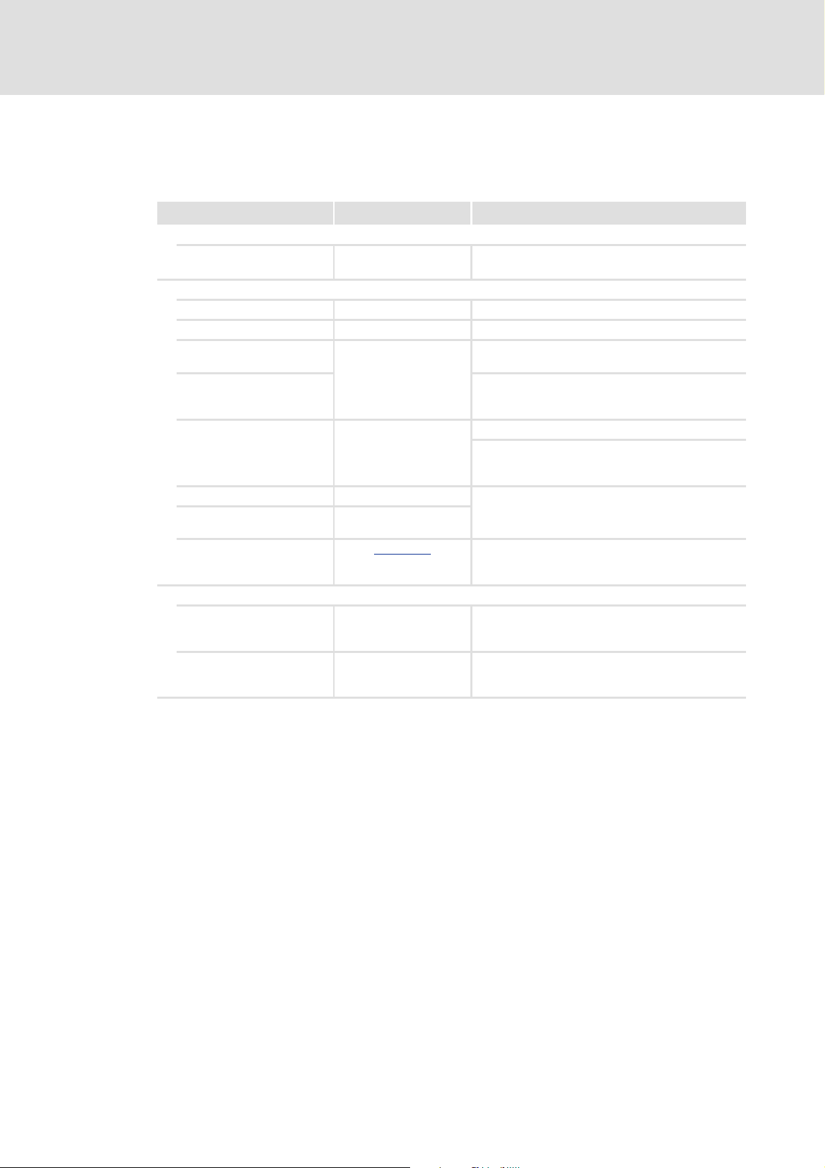
3 Introduction
Positioning means to move a workpiece/tool or a piece of material from a starting
position n to a defined targeto.
For this purpose a travel profile is to be provided in the controller, for which at least the
following profile parameters are required:
v [m/s]
B
C D
Symbol Profile parameters
Position
A
Target position or path distance to be traversed.
Speed
B
Maximum speed with which the target is to be approached.
Acceleration
C
Selection of the change in speed by which acceleration is to be carried out maximally.
Deceleration
D
Selection of the change in speed by means of which deceleration to standstill is to be maximally effected
again.
A
t [s]
A positioning can consist of several profiles which are executed in a specified mode.
For a detailed explanation of the profile parameters, please see the section "Profile
parameters". ( 44)
10 L EDS94TA10060xxxx EN 1.2 - 03/2010
Page 11
9400 Technology applications | Positioning sequence control
Example: Positioning sequence control with networking via PROFIBUS
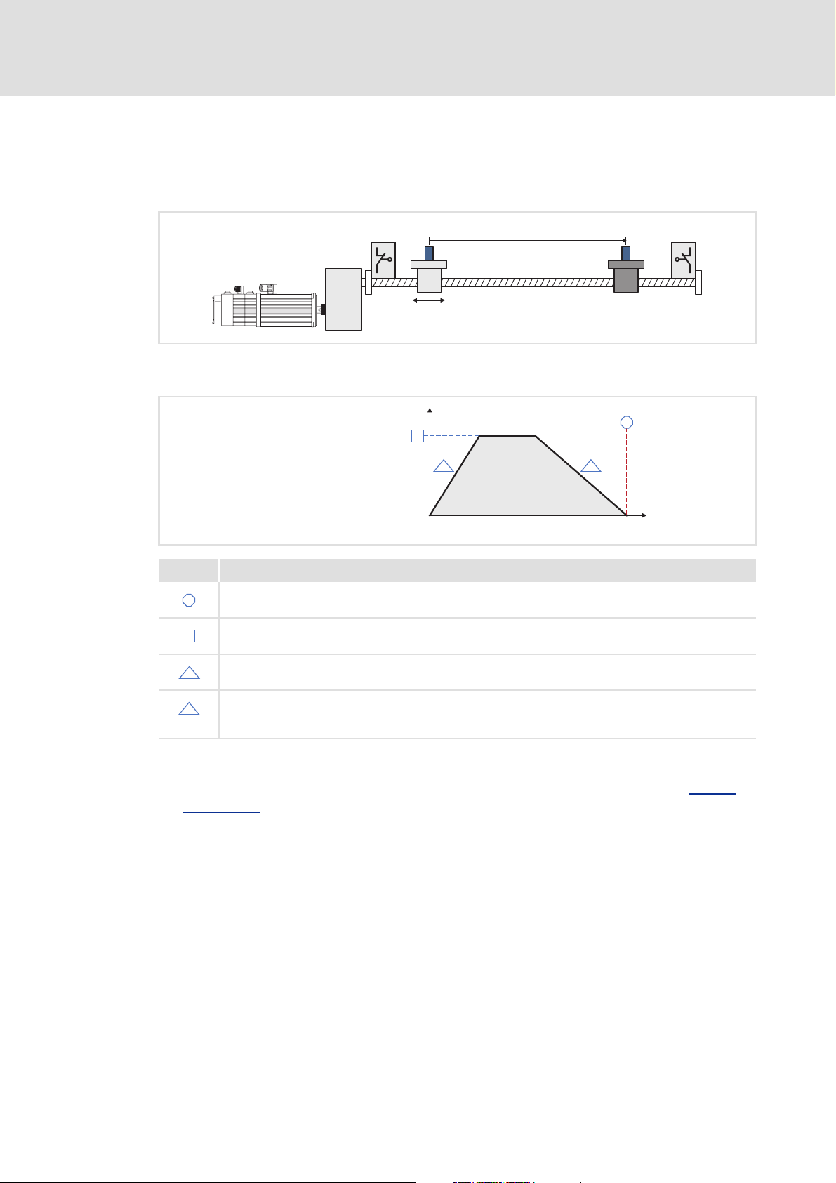
3.1 Example: Positioning sequence control with networking via PROFIBUS
Master control
Sequence control for machine (PLC)
PROFIBUS
Drive 1 Drive 2
Positioning sequence control for single drives Positioning sequence control for single drives
Introduction
Table positioning Table positioning
Firmware Firmware
Motion Control - basic drive functions:
• Positioning
•Homing
•Manual jog
•etc.
• Drive interface
• Motor interface
• Encoder evaluation
•I/O terminals
• Safety engineering
• Logbook
[3-1] Example: Positioning sequence control with networking via PROFIBUS
The positioning sequence control utilises the traversing blocks of the table positioning
and like this activates the basic function "Positioning" containing the profile
generation.
Here, the positioning sequence control only control the "own motor".
The sequence of the motor/tool/material control are defined in the positioning
sequence control.
Motion Control - basic drive functions:
• Positioning
•Homing
•Manual jog
•etc.
• Drive interface
•Motor interface
• Encoder evaluation
•I/O terminals
• Safety engineering
• Logbook
EDS94TA10060xxxx EN 1.2 - 03/2010 L 11
Page 12
9400 Technology applications | Positioning sequence control
Short setup
Application example
4Short setup
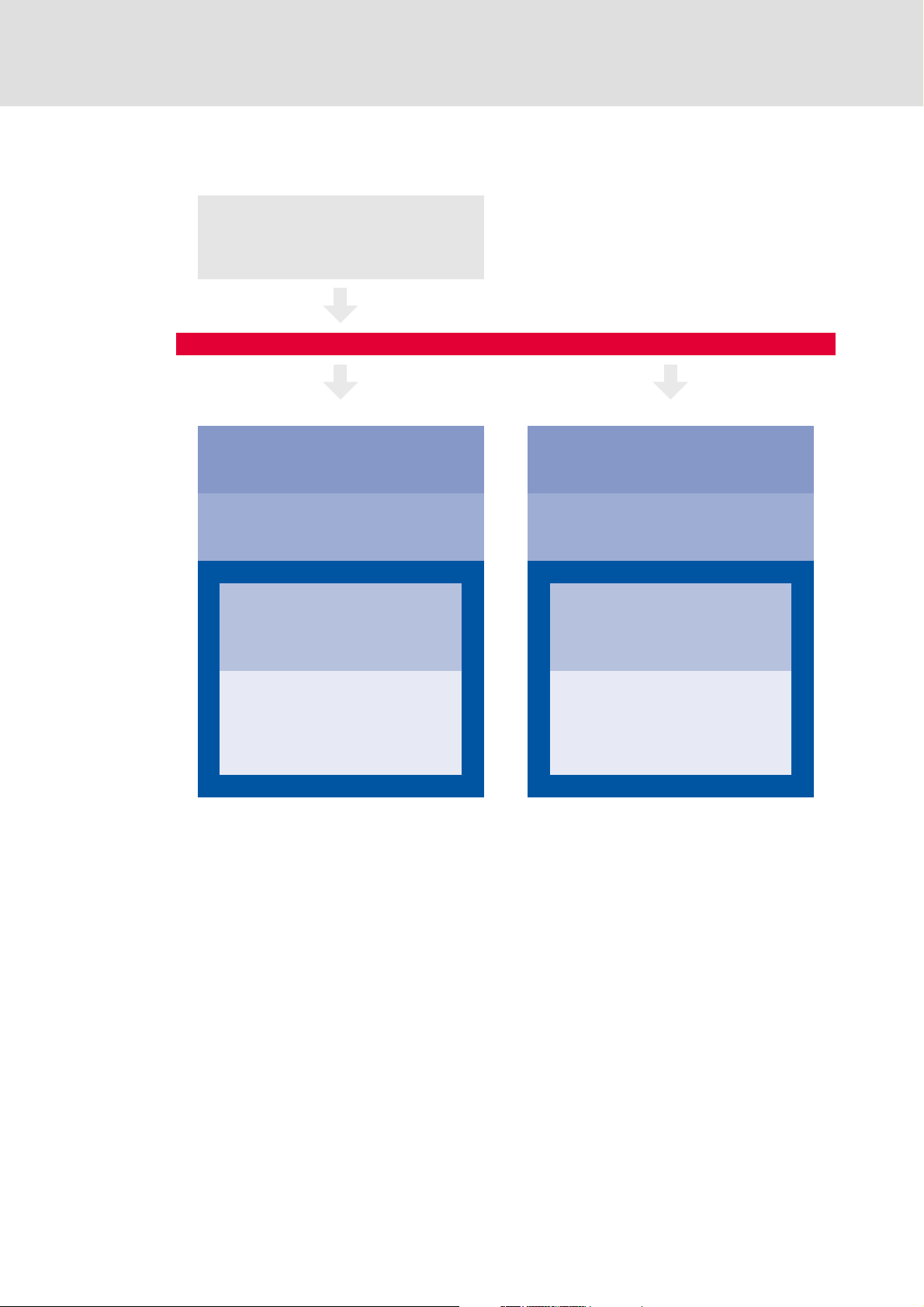
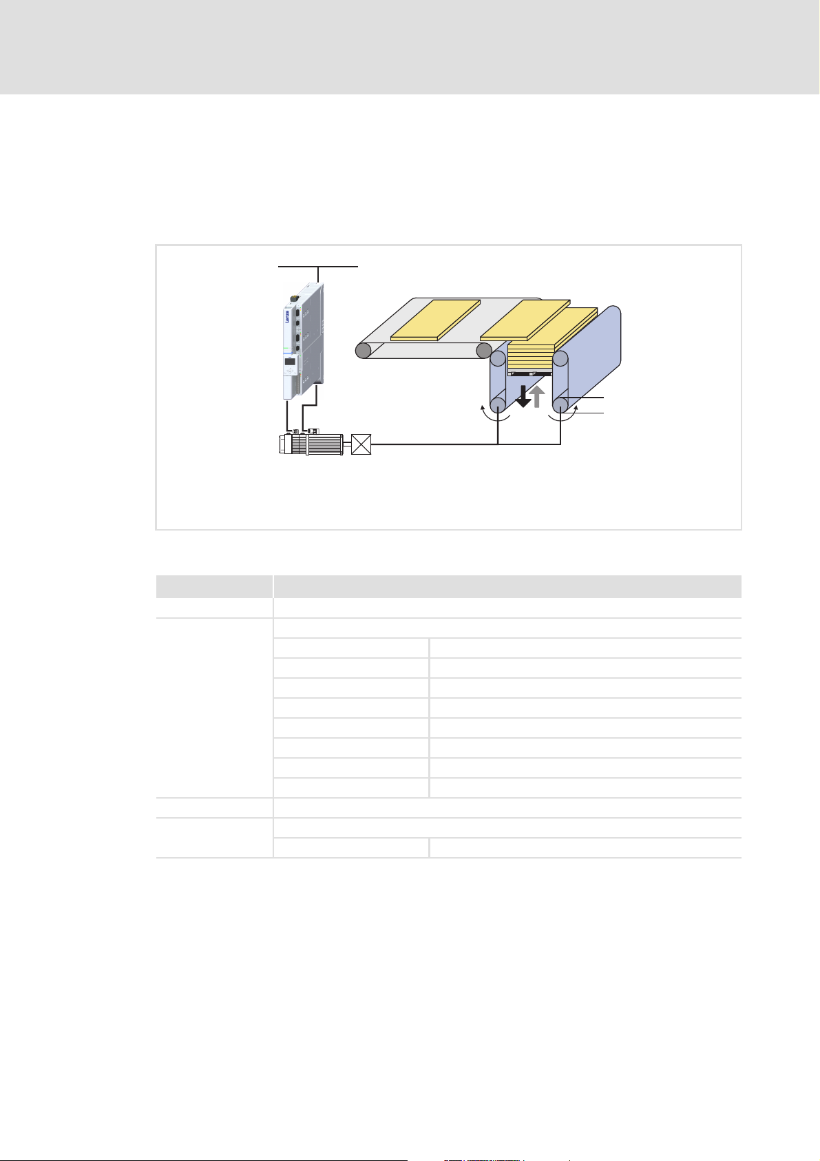
4.1 Application example
A sheet stacker is used as an application example for short setup:
3 x AC 400 V
i
1
d
1
N
= 1680 rpm
motor
i
= 12.612
1
d
= 80 mm
1
Feed constant = 250 mm/rev.
[4-1] Schematic diagram
Component Technical data
Controller 9400 SingleDrive HighLine with brake module
Motor MDFKA-090-22, 60
Type: Asynchronous servo motor
Connection: Y
Power factor: 0.8
Rated current: 8.5 A
Rated frequency: 60 Hz
Rated power: 3.8 kW
Rated speed: 1680 rpm
Rated voltage: 390 V
Brake 24 V DC
Gearbox GKS06
Gearbox factor: 12.612
12 L EDS94TA10060xxxx EN 1.2 - 03/2010
Page 13
9400 Technology applications | Positioning sequence control
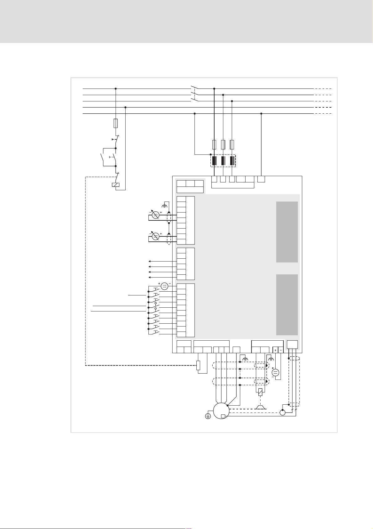
4.2 Connection diagram
Short setup
Connection diagram
L1
L2
L3
N
PE
F4
O
I
K1
J
R
B
K1
Acceleration override
Homing completed (start position)*
Max. number of sheets reached*
Positive travel range limit switch
Negative travel range limit switch
Reference switch
Reset positioning program
Start/back to start position
Stop positioning program
Speed override
Drive ready
Error active
Enable controller
Quick stop
Lower table
SB
GA
AO1
AO2
A1+
A1-
A1A1R
A2+
A2-
GO
24O
DO1
DO2
DO3
DO4
GI
RFR
DI1
DI2
DI3
DI4
DI5
DI6
DI7
DI8
X106
T1
K1
24E GE
X2
X3
X4
X5
T2
F1...F3
Z1
L1 L2
L3
X100
E94ASxExxxx
X105
Rb1
Rb2
U V
W
+
+UG
-UG
BD1
+
X107
BD2
E94AZPxxxxx
MXI1
MXI2
X7
R
B
EYF...
Y
M
3~
J
27
R
* Signal must be parameterised
[4-2] Connection diagram
EDS94TA10060xxxx EN 1.2 - 03/2010 L 13
Page 14

9400 Technology applications | Positioning sequence control
Short setup
Connection diagram
Designation Component
E94ASxExxxx 9400 Single Drive servo axis module
E94AZPxxxxx Mounting backplane
k1 Mains contactor
F1 ... F4 Fuses
Z1 Mains filter/RFI filter (option)
HF-shield termination through large-surface connection to functional earth
EYF... System cable for resolver feedback
R Resolver
R
B
Y Motor holding brake (at optional motor brake control)
Brake resistor
14 L EDS94TA10060xxxx EN 1.2 - 03/2010
Page 15

4.3 Sequence
1. After power-on, the drive indicates the status "Drive ready" by setting digital output
DO1 to HIGH level.
2. After controller enable, the positioning program is started by setting digital input DI6
to HIGH level.
3. The table traverses upwards until reaching the home switch.
– The home switch is 10 mm above the start position and connected to digital input
DI2.
4. After the homing mark has been detected, the table traverses downwards until
reaching the start position (first pick-up position).
5. The drive indicates the status "Homing completed/table in start position" by setting
digital output DO2 to HIGH level.
6. The internal sheet counter is reset to zero and stacking can start.
7. When a sheet has been added, digital input DI8 changes to HIGH level.
– After this, the table is lowered by one sheet thickness each.
9400 Technology applications | Positioning sequence control
Short setup
Sequence
8. 10 sheets can be piled up before the drive indicates the status "Maximum number of
sheets reached" by setting digital output DO3 to HIGH level.
– Then, the stack must be removed.
9. After the stack has been removed and digital input DI6 has been set to HIGH level, the
table traverses back to the start position (first pick-up position).
– A new stacking process can be started.
EDS94TA10060xxxx EN 1.2 - 03/2010 L 15
Page 16
9400 Technology applications | Positioning sequence control
Short setup
Step 1: Creating a project
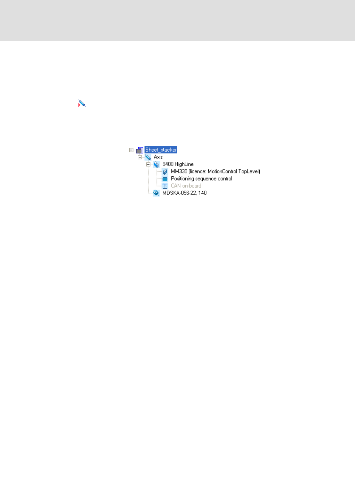
4.4 Step 1: Creating a project
1. Start »Engineer«.
2. Go to Start-up wizard and select the option "New project (empty)" and enter a name for
the project in a next step.
3. Insert the axis for the sheet stacker.
– Add the corresponding components (controller, motor, extension module) to the
axis.
– Select the application "Positioning sequence control" for the controller.
–Example project view in the »Engineer«:
16 L EDS94TA10060xxxx EN 1.2 - 03/2010
Page 17
9400 Technology applications | Positioning sequence control
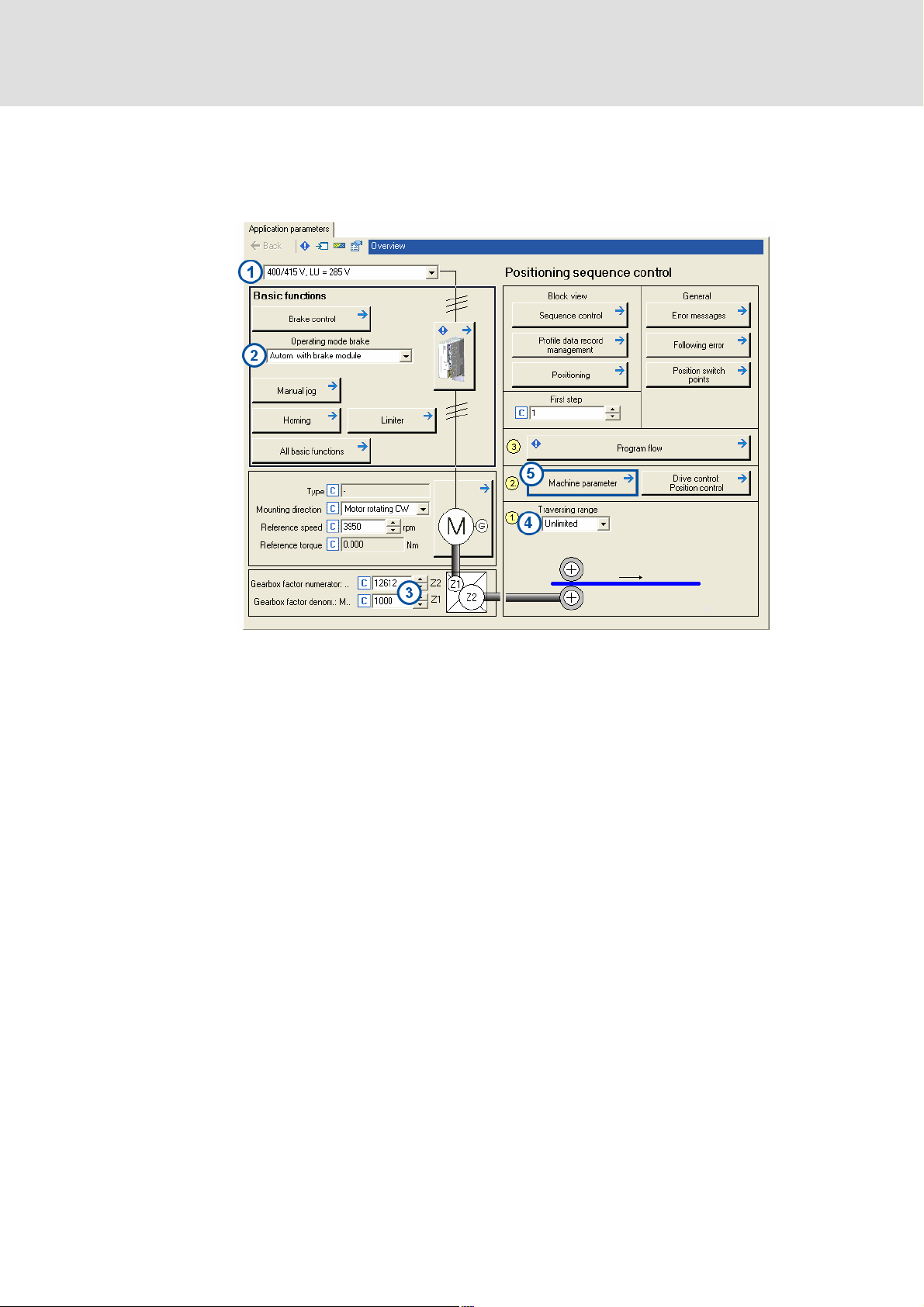
4.5 Step 2: Parameterising the application
For parameterising the application in the »Engineer«, use the Application parameters tab
which will be displayed by default when selecting the controller in the project view:
Short setup
Step 2: Parameterising the application
1. Select the mains voltage (C00173).
2. Activate automatic brake control via brake module (C02580 = "Autom. with brake
module").
3. Enter gearbox ratio as a quotient (numerator and denominator): i
1000
– Numerator (C02520) = 12612
– Denominator (C02521) = 1000
4. Select "Unlimited" as traversing range (C02528).
5. Click Machine parameter to change to the dialog level Overview Machine parameter
for further parameter setting.
= 12.612 = 12612/
1
EDS94TA10060xxxx EN 1.2 - 03/2010 L 17
Page 18
9400 Technology applications | Positioning sequence control
Short setup
Step 2: Parameterising the application
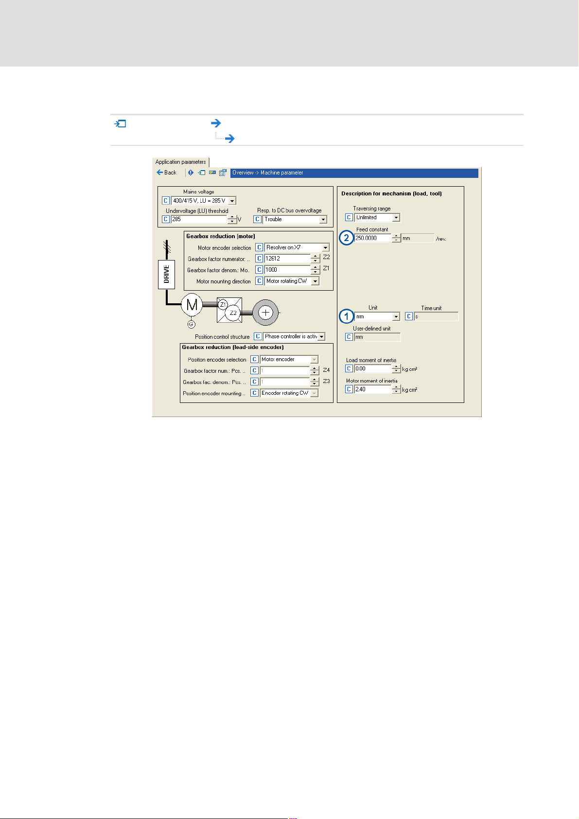
Setting the machine parameters
Go to dialog:
Overview
Machine parameter
1. Set the selection "mm" as unit (C02525).
– This parameter is used to define the real unit of the machine for the selection of
physical values (e. g. speeds, accelerations and decelerations).
2. Set feed constant (C02524).
– The feed constant corresponds to the motion of the machine at one revolution of the
gearbox output shaft.
– For the sheet stacker: Feed constant = 250 mm/rev.
3. Click Back to go back to the Overview dialog level.
4. In the Overview dialog level, click Program flow to change to the dialog level Overview
Program flow and select the positioning program.
18 L EDS94TA10060xxxx EN 1.2 - 03/2010
Page 19
9400 Technology applications | Positioning sequence control
4.6 Step 3: Parameterising the program flow
The program flow of the positioning sequence control is parameterised in the dialog level
Overview Program flow:
Short setup
Step 3: Parameterising the program flow
Basic procedure
In the default setting the sequence table contains a small "Positioning program", which
first rotates the axis 360° clockwise and afterwards 360° counter-clockwise.
Proceed as follows to define the desired program flow:
1. Select the program step (1 .... 100) to be edited on the left in the sequence table.
2. Select the action type for the selected program step by clicking it.
– If the selected action type provides more than one action, the next free action will be
automatically suggested in the Selection Action Number list field.
– Enter a comment on the action (option).
3. Set parameters of the action.
– If required, call the corresponding subsequent dialogs.
4. Repeat steps 1 ... 3 until all actions required for the program flow have been
parameterised (see the following sections).
5. Click Back to go back to the Overview dialog level.
EDS94TA10060xxxx EN 1.2 - 03/2010 L 19
Page 20
9400 Technology applications | Positioning sequence control
Short setup
Step 3: Parameterising the program flow
4.6.1 Program step 1: Homing
Action Comment
Homing with homing mark (home switch at digital input DI2), after homing, approach start position
(0 mm).
The "Homing" action does not have its own parameters. The settings for homing are made
via the parameters of the basic function "Homing":
1. Select "cw_Rn_TP" as homing mode (C02640).
2. Select the position of the home switch (10 mm) as home position (C02642).
3. Select the position of the first sheet (0 mm) as home target position (C02643).
4. If necessary, adapt the profile parameters for homing to your application.
4.6.2 Program step 2: Setting counter 1 to "0"
Action Comment Parameter Setting
Step 2: Set counter 1 to "0". Selection Action Number: 1
0
00
Set
Counter no.: 1
Start value: 0
20 L EDS94TA10060xxxx EN 1.2 - 03/2010
Page 21
9400 Technology applications | Positioning sequence control
4.6.3 Program step 3: Positioning action 1
Action Comment Parameter Setting
When input 8 of sequence control is set to "1", lower
table relatively by 20 mm.
In the Lenze setting, sequence control input 8 is
connected to digital input DI8.
Click Profile settings to open the following dialog box:
Short setup
Step 3: Parameterising the program flow
Selection Action Number: 1
Start with: Input 8
Profile no.: 1
Jump destination: 0
1. Select Profile no. 1.
2. Select "Relative" as positioning mode.
3. Select the profile parameters as described above.
4. Click Back to close the dialog box again.
EDS94TA10060xxxx EN 1.2 - 03/2010 L 21
Page 22
9400 Technology applications | Positioning sequence control
Short setup
Step 3: Parameterising the program flow
4.6.4 Program step 4: Counting the sheets
Action Comment Parameter Setting
Count the sheets and go back to program step 3,
3
1
2
4
unless 10 sheets are reached.
4.6.5 Program step 5: Setting the status output
Action Comment Parameter Setting
Set sequence control output 1 to "1", when
maximum number of sheets (10) is reached.
Selection Action Number: 1
Comparison function: Count <
Comparison value: 10
Selection Action Number: 1
Output for A switching: Output 1
Signal state for A switching:
Counter no.: 1
comparison
value
Step value: 1
Sequence step: 3
Output for B switching: Deactivated
Signal state for B switching:
Tip!
In a later step, sequence control output 1 will be connected with digital output
DO3.
22 L EDS94TA10060xxxx EN 1.2 - 03/2010
Page 23
9400 Technology applications | Positioning sequence control
4.6.6 Program step 6: Positioning action 2
Action Comment Parameter Setting
When sequence control input 6 is set to "1", go back
to start position.
Tip!
In a later step, sequence control input 6 will be connected with digital input DO6.
Click Profile settings to open the following dialog box:
Short setup
Step 3: Parameterising the program flow
Selection Action Number: 2
Start with: Input 6
Profile no.: 2
Jump destination: 0
1. Select Profile no. 2.
2. Select "Absolute" as positioning mode.
3. Select the profile parameters as described above.
4. Click Back to close the dialog box again.
EDS94TA10060xxxx EN 1.2 - 03/2010 L 23
Page 24
9400 Technology applications | Positioning sequence control
Short setup
Step 3: Parameterising the program flow
4.6.7 Program step 7: Resetting the status output
Action Comment Parameter Setting
Reset sequence control output 1 to "0", when start
position is reached.
4.6.8 Program step 8: Going back to program step 2
Action Comment Parameter Setting
Go back to program step 2. Selection Action Number: 1
0
1
Selection Action Number: 2
Output for A switching: Output 1
Signal state for A switching:
Output for B switching: Deactivated
Signal state for B switching:
Jump destination: 2
Jump input: Continue
with next
step
24 L EDS94TA10060xxxx EN 1.2 - 03/2010
Page 25

9400 Technology applications | Positioning sequence control
Step 4: Parameterising the multiplexer for the digital outputs
4.7 Step 4: Parameterising the multiplexer for the digital outputs
1. Go to the All parameters tab.
2. Set the following multiplexer parameters:
Parameter Setting
C03100/2 X digital output 2 of Homing completed
C03100/3 X digital output 3 of Sequence control output 1
Short setup
EDS94TA10060xxxx EN 1.2 - 03/2010 L 25
Page 26

9400 Technology applications | Positioning sequence control
Short setup
Step 5: Transferring the application to the controller
4.8 Step 5: Transferring the application to the controller
Note!
The transferred application is always stored in the first application memory
location in the memory module of the controller.
The preinstalled technology applications on the following memory locations are
still available.
1. Update devices.
– Set the checkmark in the control field Recreate all.
–Click Create to start the compiling process.
2. Go online and transfer the application to the controller.
– With an online connection, the »Engineer« displays the current controller parameter
settings with a yellow background colour.
26 L EDS94TA10060xxxx EN 1.2 - 03/2010
Page 27

9400 Technology applications | Positioning sequence control
Step 6: Controlling the application via terminals
4.9 Step 6: Controlling the application via terminals
Terminal assignment
Terminal Signal (Lenze setting)
X3 AI1-
X5 DI1 Quick stop
Selection for speed override
AI1+
Speed/acceleration override
AI2-
Selection for acceleration override
AI2+
Speed/acceleration override
• If DI1 is set to LOW level, the positioning program is interrupted and drive is decelerated to
standstill within the deceleration time set for the quick stop function independent of the
setpoint selection.
• After the quick stop function is deactivated, a new LOW/HIGH edge is required at DI6 in order
that the positioning program is continued with the next step.
Quick stop
DI2 Connection of reference switch/touch probe sensor
Action type "Homing"
DI3
Connection of travel range limit switch for basic function "Limiter
DI4
• DI3 = positive travel range limit switch, DI4 = negative travel range limit switch.
• The inputs respond to the FALSE state (fail-safe).
DI5 Reset error and positioning program
• By means of a LOW-HIGH edge an existing error status can be reset if the cause of the fault is
removed. At the same time the positioning program is reset.
DI6 Start positioning program/back to start position
Control of the sequence table
DI7 Stop positioning program (break)
Control of the sequence table
DI8 Lower table
( 56)
( 53)
( 53)
( 36)
( 43)
( 43)
Short setup
". ( 57)
Procedure
1. Enable controller: Set digital input RFR to HIGH level.
2. Deactivate quick stop: Set digital input DI1 to HIGH level.
3. Start sequence control: Set digital input DI6 to HIGH level.
EDS94TA10060xxxx EN 1.2 - 03/2010 L 27
Page 28

9400 Technology applications | Positioning sequence control
Parameter setting & configuration
Basic signal flow
5 Parameter setting & configuration
5.1 Basic signal flow
The functional core of the positioning sequence control is formed by the sequence table
and the profile data management, which transmit the required control signals and profile
data to the basic drive function "Positioning".
Positioning sequence control
DI2
Reset
Sequencer
input 8
Acceleration override
Sequencer
DI5
DI6
DI7
DI8
024
Speed override
PositionerTable
Profiles
Override
Enable
AIN1
AIN2
LS_Homing
3
LS_Positioner
n
LS_ManualJog
ç
n
5
[5-1] Signal flow of the TA " Positioning sequence control" (schematic diagram)
Basic drive functions
LS_Stop
internal
n
status machine
0-100 100 200
6
Status
machine
(basic drive
functions)
t
DI1
LS_Quickstop
è
n
STOP
t
78
LS_Brake
t
91
M
LS_Limiter
n
t
DI4
DI3
t
Positioning sequence control
Sequence table
Profile data management
Speed/acceleration override
Basic drive functions
Homing
Positioning
Manual jog
Stop
Quick stop
Limiter
Brake control (optional)
28 L EDS94TA10060xxxx EN 1.2 - 03/2010
Page 29

9400 Technology applications | Positioning sequence control
5.2 Basic settings
5.2.1 Machine parameters
The machine parameters describe e.g. the motor end of the mechanics
M
used.
The setting of the machine parameters in the »Engineer» is carried out on
the Application parameters tab in the dialog level Overview Machine
parameters.
Tip!
In the »Engineer« the most important machine parameters can be directly adapted
to the machine on the Application parameters tab in the topmost Overview dialog
level.
Parameter setting & configuration
Basic settings
Short overview of machine parameters
Parameter Lenze setting
Value Unit
C00173 Mains voltage 400/415 V
C00174 Undervoltage (LU) threshold 285 V
C00600 Resp. to DC bus overvoltage Trouble
C02520 Gearbox factor numerator: Motor 1
C02521 Gearbox factor denom: Motor 1
C02527 Motor mounting direction Motor rotating CW
C02570 Position control structure Phase control
C02522 Gearbox factor num.: Pos. enc. 1
C02523 Gearbox factor denom.: Pos. enc. 1
C02529 Mounting direction of position encoder Encoder rotating CW
Description of the mechanics (load, tool)
C02528 Traversing range Limited
C02524 Feed constant 360.0000 unit
C02525 Unit °
C02526 User-defined unit °
C02533 Time unit s
C00273/1 Motor moment of inertia Motor-dependent kg cm
C00273/2 Load moment of inertia 0.00 kg cm
2
2
EDS94TA10060xxxx EN 1.2 - 03/2010 L 29
Page 30

9400 Technology applications | Positioning sequence control
Parameter setting & configuration
Basic settings
5.2.2 Traversing range
By setting the traversing range the machine type/measuring system is set:
Traversing range
Unlimited The drive can traverse optionally in both directions without
M
Limited After reaching the position limits, the drive must travel in the
M
Modulo The measuring system is repeated.
M
reaching limitations.
• Positioning here generally is effected in the positioning
modes "Relative with/without TP" or "Speed with/
without TP".
• The positioning measuring system is reset to zero with
every new positioning process.
• By homing, the positioning measuring system receives a
fixed reference point (zero point), so that also the
positioning modes "Absolute with/without TP"can be
used. Then also the software limit positions for limiting
the traversing range are provided.
opposite direction again.
• For positioning, the home position has to be known. By
homing, the positioning measuring system receives a
fixed reference point (zero point).
• Basically, monitoring to the internally maximum usable
value range (±2
position monitoring of the internal value range). An
overflow of the value range results in the loss of the home
position.
• Additionally parameterisable software limit positions can
be activated on the user side for limiting the travel range.
• If the cycles n set are exceeded a defined overflow occurs.
The cycle typically corresponds to a rotation or tool
distance in a rotative system.
• For positioning, the home position has to be known.
• Software limit positions are not effective.
• Absolute targets can be approached by exceeding the
measuring system limit, e.g. from 10° via 0° to 350°.
31
increments) takes place (software limit
Parameter setting: Tab Application parameters dialog level Overview
Parameter Lenze setting
Value Unit
C02528 Traversing range Limited
C02536 Cycle (only relevant for traversing range "Modulo") 360.0000 unit
30 L EDS94TA10060xxxx EN 1.2 - 03/2010
Page 31

9400 Technology applications | Positioning sequence control
5.2.3 Position control
In the dialog level Overview LS_Positioner and the subordinate dialog levels, you can
adapt the parameters for the position control, if necessary.
Parameter Lenze setting
C00254 Phase controller gain 20.00 1/s
C02553 Position controller gain 20.00 1/s
C02556 Position controller limitation 214748.3647 unit/s
Parameter setting & configuration
Basic settings
Value Unit
EDS94TA10060xxxx EN 1.2 - 03/2010 L 31
Page 32

9400 Technology applications | Positioning sequence control
Parameter setting & configuration
Program flow
5.3 Program flow
The program flow of the positioning sequence control is selected according to a sequence
table which can contain up to 100 references to "actions".
Basic drive functions
n
0-100 100 200
t
LS_Quickstop
è
n
t
LS_Stop
internal
status machine
Status
machine
(basic drive
functions)
STOP
LS_Brake
t
M
LS_Limiter
n
t
t
Reset
Sequencer
input 8
Positioning sequence control
Sequencer
DI5
DI6
DI7
DI8
PositionerTable
Profiles
Override
Enable
LS_Homing
LS_Positioner
n
LS_ManualJog
ç
n
[5-2] Sequence table (schematic diagram)
What is an action?
An action comprises a clear functionality which is described with a few parameters.
Different action types are available which serve to implement, for instance, program
branching, switching operations, waiting times and counters.
0
1
1
2
n
0
00 1
Set
3
2
4
Standby End
Before every action type a defined number of actions is available which can be
individually parameterised. The parameters of the actions of the same type only differ
in the subcode.
An action can be used in several steps if always exactly the same task is to be carried
out.
After an action has been processed, the action in the next step of the sequence table is
automatically processed unless it is jumped to another step in the sequence table due
to a branch.
One action can be maximally processed per computing cycle.
32 L EDS94TA10060xxxx EN 1.2 - 03/2010
Page 33

9400 Technology applications | Positioning sequence control
5.3.1 Overview of action types
Action type Function/parameter
Homing
In order to execute a homing process, the action type "Homing" is available which activates the basic
function "Homing".
Note: The "Homing" action does not have its own parameters. The settings for homing are made via
the parameters of the basic function "Homing".
Positioning
To execute a profile, 50 actions of the "Positioning" type are available.
• The execution of the adjusted profile is only started with activated waiting function if the
sequencer input selected for the waiting function accepts the selected signal state.Sequencer
inputs ( 40)
Parameter Information
C04513/1...50 Profile number Specification of the profile to be executed.
C04511/1...50 Input for waiting
C04512/1...50 Signal state for
C04514/1...50 Sequence step Step inside the sequence table which will be processed after
C04515/1...50 Watchdog time Monitoring time within which positioning must be
C04516/1...50 Watchdog
Branching
25 actions of type "Branching" are available for conditional and unconditional branches (jumps).
0
• A branch to the indicated step is executed when the selected sequencer input has the selected
1
signal state at the time of processing. If not, the sequence step is processed in the sequence
table.Sequencer inputs
Parameter Information
C04530/1...25 Input for
C04531/1...25 Comparison
C04532/1...25 Sequence step in
function
waiting function
sequence step
( 40)
comparison
value
case of equality
Parameter setting & configuration
Program flow
• Press the "Set up profile" button to open a dialog box to
enter the corresponding profile parameters.
• In this dialog a sequence profile can also be set.
Sequencer input 1 ... 32 to be evaluated.
• With the default setting "0" the waiting function is
skipped and the profile execution is started immediately.
Profile processing is only started when the sequencer input
to be evaluated is in this state.
the profile has been executed.
completed. Otherwise, a branch to the watchdog sequence
step defined in C04516 is executed.
Executed when the watchdog time has expired.
Sequencer input 1 ... 32 to be evaluated.
• With the default setting "0" a branch to the adjusted
sequence step is executed.
State in which the sequencer input to be evaluated is
compared.
If the sequencer input to be evaluated equals the
comparison value, a branch to the step set here is executed.
In case of inequality or "0" setting, the next step in the
sequence table is processed.
EDS94TA10060xxxx EN 1.2 - 03/2010 L 33
Page 34

9400 Technology applications | Positioning sequence control
Parameter setting & configuration
Program flow
Action type Function/parameter
Variable branching
For variable branches (jumps) 5 actions of type "Variable branching" are available.
1
• The branch to one of 20 possible steps is executed depending on the value in C03001 ... C03005
2
n
Switching
Set counter
0
00
Set
at the time or processing.
• The parameters C03001 ... C03005 are firmly assigned to the five available actions:
–C03001 determines the branch for action 1.
–C03002 determines the branch for action 2, etc.
Example:
If C03002 is assigned to the value "15" at the time of processing the action no. 2, it is branched to
the step which is entered in the parameter "Sequence step at branch value 15" for action no. 2
(C04554/2).
Parameter Information
C04540/1...5 Sequence step at
branch value 1
C04541/1...5 Sequence step at
branch value 2
... ... ...
C04559/1...5 Sequence step at
branch value 20
In order to switch digital output signals 25 actions of type "Switching" are available.
• Each action can set two selectable sequencer outputs independently of each other to FALSE or
TRUE. Sequencer outputs
Parameter Information
C04520/1...25 Output for A
switching
C04521/1...25 Signal state for A
switching
C04522/1...25 Output for B
switching
C04523/1...25 Signal state for B
switching
10 actions of type "Set counter" are available for setting one of the 10 available counters to a certain
starting value.
• The 10 actions of type "Set counter" are not firmly assigned to the 10 actions of the "Counting"
type.
• You can use, for instance, an action of type "Set counter" to set a counter to a value and later you
can set the same counter with another action of type "Set counter" to another value.
Parameter Information
C04580/1...10 Counter selection With the setting "0" the setting of the counter is deactivated.
C04581/1...10 New counter
content
C04582/1...10 Current counter
content
Step which is executed next when C03001 ... C03005 = "1".
• With the default setting "0" the branching is deactivated
(sequence step is processed).
Step which is executed next when C03001 ... C03005 = "2".
• In the default setting "0", branching is deactivated and
the next step in the sequence table is processed.
Step which is executed next when C03001 ... C03005 = "20".
• In the default setting "0", branching is deactivated and
the next step in the sequence table is processed.
( 41)
Sequencer output 1 ... 32 to be switched.
• With the setting "0" switching is deactivated.
State to which the sequencer output is to be set.
Sequencer output 1 ... 32 to be switched.
• With the setting "0" switching is deactivated.
State to which the sequencer output is to be set.
-2147483648 ... 2147483648
Read only
34 L EDS94TA10060xxxx EN 1.2 - 03/2010
Page 35

9400 Technology applications | Positioning sequence control
Action type Function/parameter
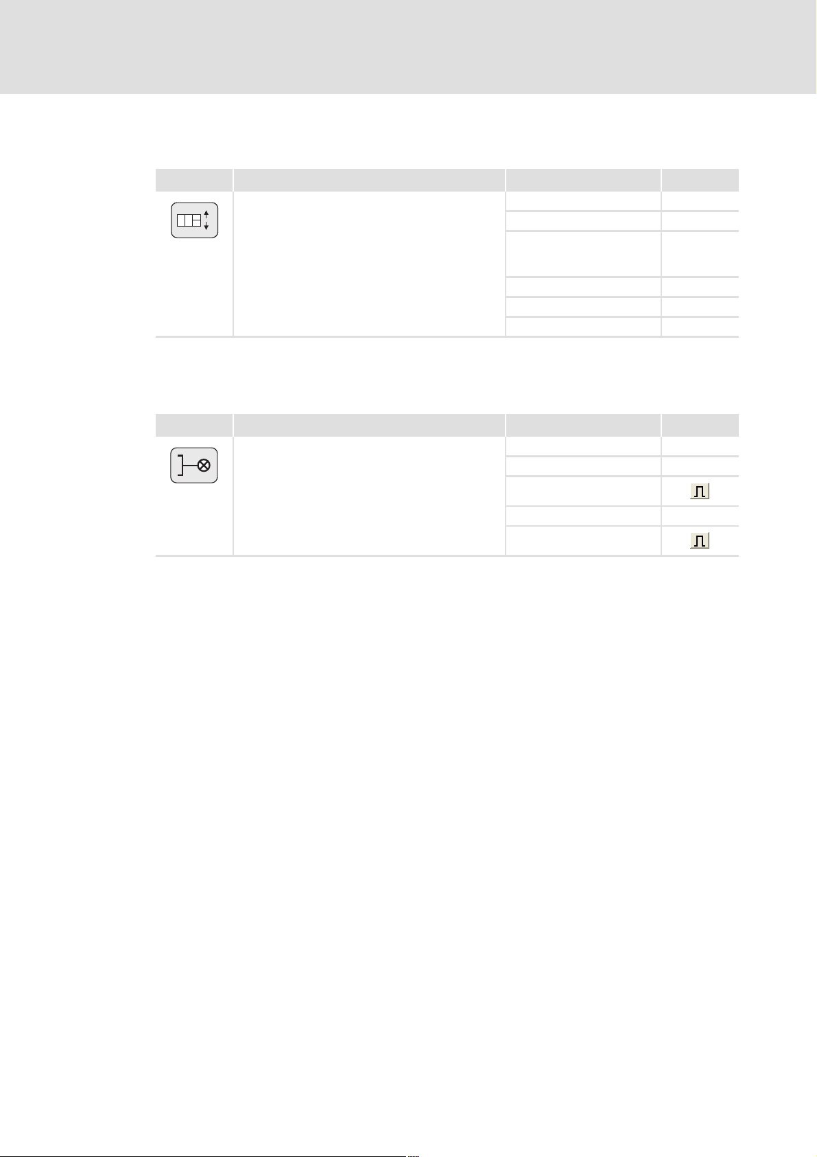
Count
25 actions of type "Count" are available for counting processes.
3
1
2
4
Wait
Stand-by
Standby
Program end
End
• With each action processing the counter content of the counter selected is increased or reduced
by the specified step value depending on the setting (count upwards or downwards).
• When the comparison condition for comparing the counter content with an adjustable
comparison value is fulfilled, a branch to any step is possible.
• 10 actions of type "Set counter" are available for setting a counter to a starting value.
Parameter Information
C04590/1...25 Counter selection With the setting "0" the setting of the counter is deactivated.
C04591/1...25 Step value Value by which the counter is increased or reduced.
C04592/1...25 Comparison
C04593/1...25 Sequence step When the set comparison condition is met, a branch to the
C04594/1...25 Comparison
25 actions of type "Wait" are available for the insertion of wait times into the program flow.
• The sequence step is only processed after the waiting time has elapsed or when the selected
sequencer input has the selected signal state at the time of processing.Sequencer inputs
( 40)
Parameter Information
C04571/1...25 Waiting time With setting "0", the waiting time is deactivated.
C04572/1...25 Input for waiting
C04573/1...25 Signal state for
5 actions of type "Stand-by" are available for the temporary activation of a setpoint follower.
• For a sensible use of the "Standby" action, appropriate signal combinations are required in the
(enabled) function block editor.
• The setpoint follower is enabled until the condition for exiting the stand-by is met.
Parameter Information
C04601/1...5 Input for "Stand-
C04602/1...5 Signal state for
To define the program end in the sequence table or delete a program step, the action of type
"Program end" is available.
value
condition
function
waiting function
by" end
"Stand-by" end
Parameter setting & configuration
Program flow
• Range: -2147483648 ... 2147483648
Value with which the counter is compared.
• Range: -2147483648 ... 2147483648
step set here is executed.
If the condition is not met, the next step in the sequence
table is processed instead.
Selection of the condition for the comparison of the counter
content with the comparison value.
Sequencer input 1 ... 32 to be evaluated.
• The sequence step will be processed when this input has
the set state, but no later than after the set waiting time
has elapsed.
Required state for completing the waiting function.
Sequencer input 1 ... 32 to be evaluated.
Only if the sequencer input to be evaluated has this state,
the standby step is exited, and the next step in the sequence
table is processed.
EDS94TA10060xxxx EN 1.2 - 03/2010 L 35
Page 36

9400 Technology applications | Positioning sequence control
Parameter setting & configuration
Program flow
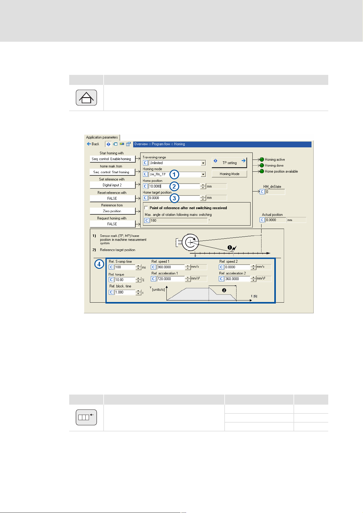
5.3.2 Action type "Homing"
In order to execute a homing process, the action type "Homing" is available for the
sequence table which activates the basic function "Homing".
Positioning sequence control
DI5
DI6
DI7
DI8
Sequencer
Enable/activate
homing
State "homing done"
Reset
Sequencer
input 8
[5-3] "Homing" (schematic diagram for limited traversing range)
Basic drive functions
DI2
LS_Homing
(basic drive
0-100 100 200
functions)
Status
machine
M
Note!
The "Homing" action for the sequence table does not have its own parameters.
The settings for homing are made via the parameters of the basic function
"Homing".
Parameter setting: Tab Application parameters dialog level Overview Homing
Parameter Lenze setting
C02528 Traversing range Limited
C02640 Homing mode Set home pos. directly
C02642 Home position 0.0000 unit
C02643 Homing: Target position 0.0000 unit
C02644 Homing: Speed 1 360.0000 unit/s
C02645 Homing: Acceleration 1 720.0000 unit/s
C02646 Homing: Speed 2 180.0000 unit/s
C02647 Homing: Acceleration 2 360.0000 unit/s
C02648 Homing: S-ramp time 100 ms
C02649 Homing: Torque limit 10.00 %
C02650 Homing: Blocking time 1.000 s
C02652 Ref. pos. after mains switching Delete
C02653 Max. rot. ang. aft. mns. swtch. 180 °
Value Unit
2
2
36 L EDS94TA10060xxxx EN 1.2 - 03/2010
Page 37

9400 Technology applications | Positioning sequence control
Parameter setting & configuration
Program flow
Control inputs of the function Signal configuration
Lenze setting Control input (Multiplexer parameters)
Sequencer
Enable Homing
Sequencer
Activate Homing
DIGIN 2 Home mark C03160/3
Zero position Home position C03163
+100 % Homing override C03186/4
Request homing C03160/1
Start homing C03160/2
FALSE Set home position C03160/4
FALSE Reset home position C03160/5
EDS94TA10060xxxx EN 1.2 - 03/2010 L 37
Page 38

9400 Technology applications | Positioning sequence control
Parameter setting & configuration
Program flow
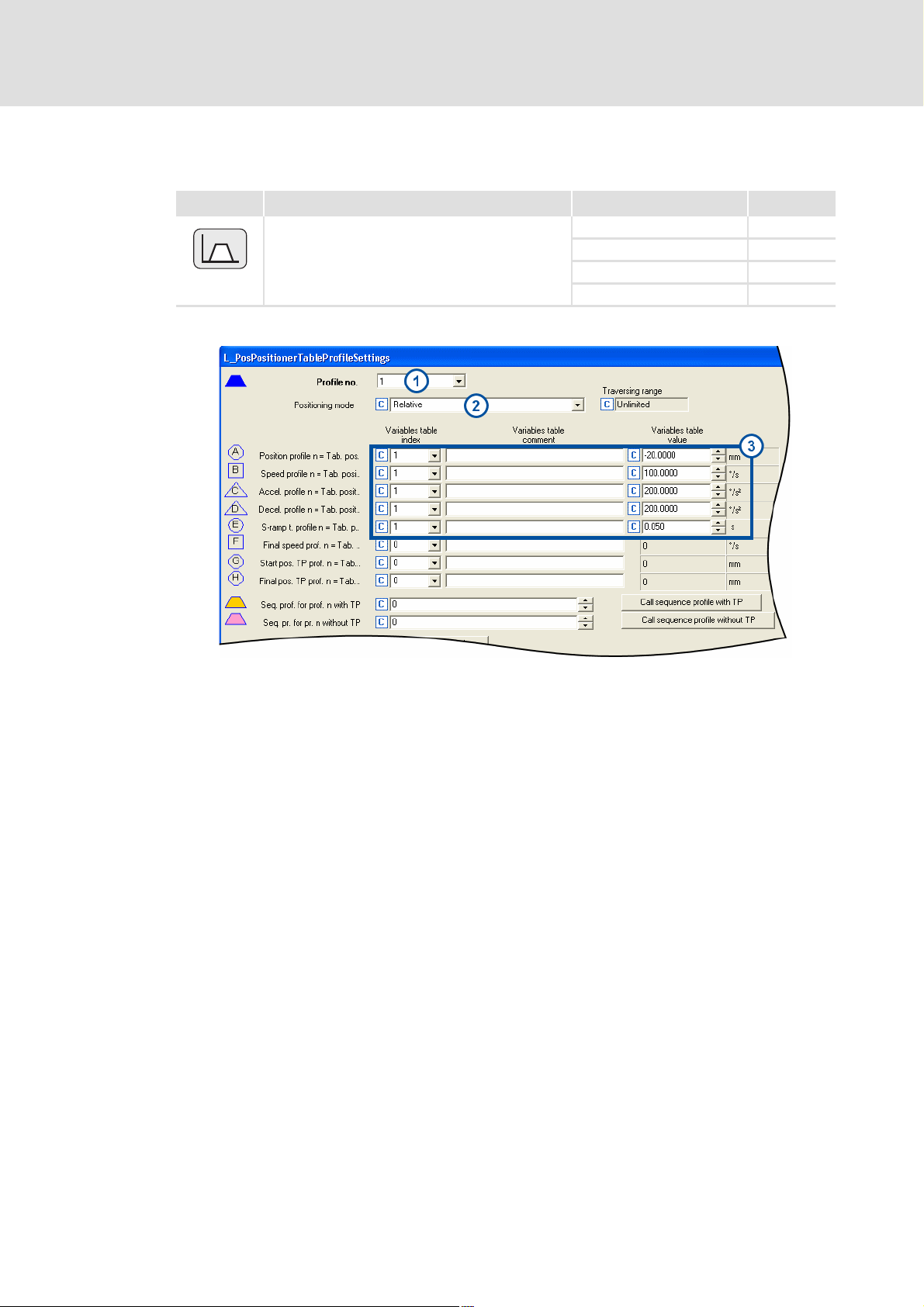
5.3.3 Action type "Positioning"
In order to execute a positioning process, 50 actions of "Positioning" type are available for
the sequence table which activates the basic function "Positioning":
Positioning sequence control
DI5
DI6
DI7
DI8
Sequencer
Profile
number
State "positioning done"/"drive in target"
Enable/activate
positioning
PositionerTable
Profiles
Reset
Sequencer
input 8
[5-4] "Positioning" (schematic diagram for limited traversing range)
Basic drive functions
LS_Positioner
n
Profile
data
Status
machine
(basic drive
functions)
t
M
Use the parameter Profile number of the action to select the number or the table
position of the profile to be executed. The final profile data are then given to the basic
function by the Profile data management
. ( 44)
The execution of the adjusted profile is only started with activated waiting function if
the sequencer input selected for the waiting function accepts the selected signal
state.Sequencer inputs
( 40)
38 L EDS94TA10060xxxx EN 1.2 - 03/2010
Page 39

9400 Technology applications | Positioning sequence control
5.3.4 Action type "Variable branching"
For variable branches (jumps) 5 actions of type "Variable branching" are available for the
sequence table.
1
2
n
Branch 1 value
C03001
Parameter setting & configuration
Program flow
The branch to one of 20 possible steps
is executed in the Lenze setting
depending on the value in
C03001 ... C03005 at the time or
processing.
<1
>20
Following
step
[5.1] Principle of the variable branch (here for action no. 1)
12 20
Next step Next step Next step
C04540/1 C04541/1 C04559/1
Tip!
Instead of the parameters C03001 ... C03005 you can also assign other signal
sources of the application to the "branch" inputs via multiplexer parameters.
Parameter setting: Tab Application parameters dialog level Overview Sequence
control
Parameter Lenze setting
C03001 Branch value 1 1
C03002 Branch value 2 1
C03003 Branch value 3 1
C03004 Branch value 4 1
C03005 Branch value 5 1
The parameters C03001 ... C03005 are
firmly assigned to the five available
actions, i.e. C03001 determines the
branch for action 1, C03002 for
action 2, etc.
Value Unit
Control inputs of the function Signal configuration
Lenze setting Control input (Multiplexer parameters)
C03001 Sequencer branch 1 C03079/1
C03002 Sequencer branch 2 C03079/2
C03003 Sequencer branch 3 C03079/3
C03004 Sequencer branch 4 C03079/4
C03005 Sequencer branch 5 C03079/5
EDS94TA10060xxxx EN 1.2 - 03/2010 L 39
Page 40

9400 Technology applications | Positioning sequence control
Parameter setting & configuration
Program flow
Example
The following example illustrates the function of the variable branch based on a program
flow which contains, among other things, two actions of the "Variable branching" type.
Step 12
Step 13
[5.2] Example "Variable branch"
5.3.5 Sequencer inputs
In order to control conditional branches and the optional waiting function of some action
types during the program flow, 32 sequencer inputs of "BOOL" type.
The sequencer inputs 1 ... 16 can be linked with the signal sources of the application or
device interfaces in the dialog level Overview L_Sequencer Program inputs via
multiplexer parameters.
Step 14
Step 15
Step 16
Step 17
Action number:
1
2
n
Action number:
1
2
n
C030022=4
C04543/2 =16
C030033=20
C04559/3 =12
W jump to step number [C04543/2]
W jump to step number [C04559/3]
For the action types "positioning", "branching", "waiting" and "stand-by", you can
individually define for each action which of the sequencer inputs is to be called for the
corresponding function when the program is executed.
Note!
The sequencer input 8 in the Lenze setting is linked with the digital input DI8.
40 L EDS94TA10060xxxx EN 1.2 - 03/2010
Page 41

9400 Technology applications | Positioning sequence control
5.3.6 Sequencer outputs
Via a DWORD-to-BIT-converter, 32 sequencer outputs of type "BOOL" are available for
"switching" which can be set to FALSE or TRUE with the action type "switching".
These sequencer outputs can be connected with the inputs of the application or device
interfaces via multiplexer parameters.
The following table lists the corresponding module outputs of the FB interconnection
and the corresponding selection numbers for the multiplexer parameters:
Module output Signal type Selection no. Selection text
SequencerOutput.bBit0 551 Sequencer output 1
SequencerOutput.bBit1 552 Sequencer output 2
SequencerOutput.bBit2 553 Sequencer output 3
... ... ...
SequencerOutput.bBit31 582 Sequencer output 32
Parameter setting & configuration
Program flow
EDS94TA10060xxxx EN 1.2 - 03/2010 L 41
Page 42

9400 Technology applications | Positioning sequence control
Parameter setting & configuration
Program flow
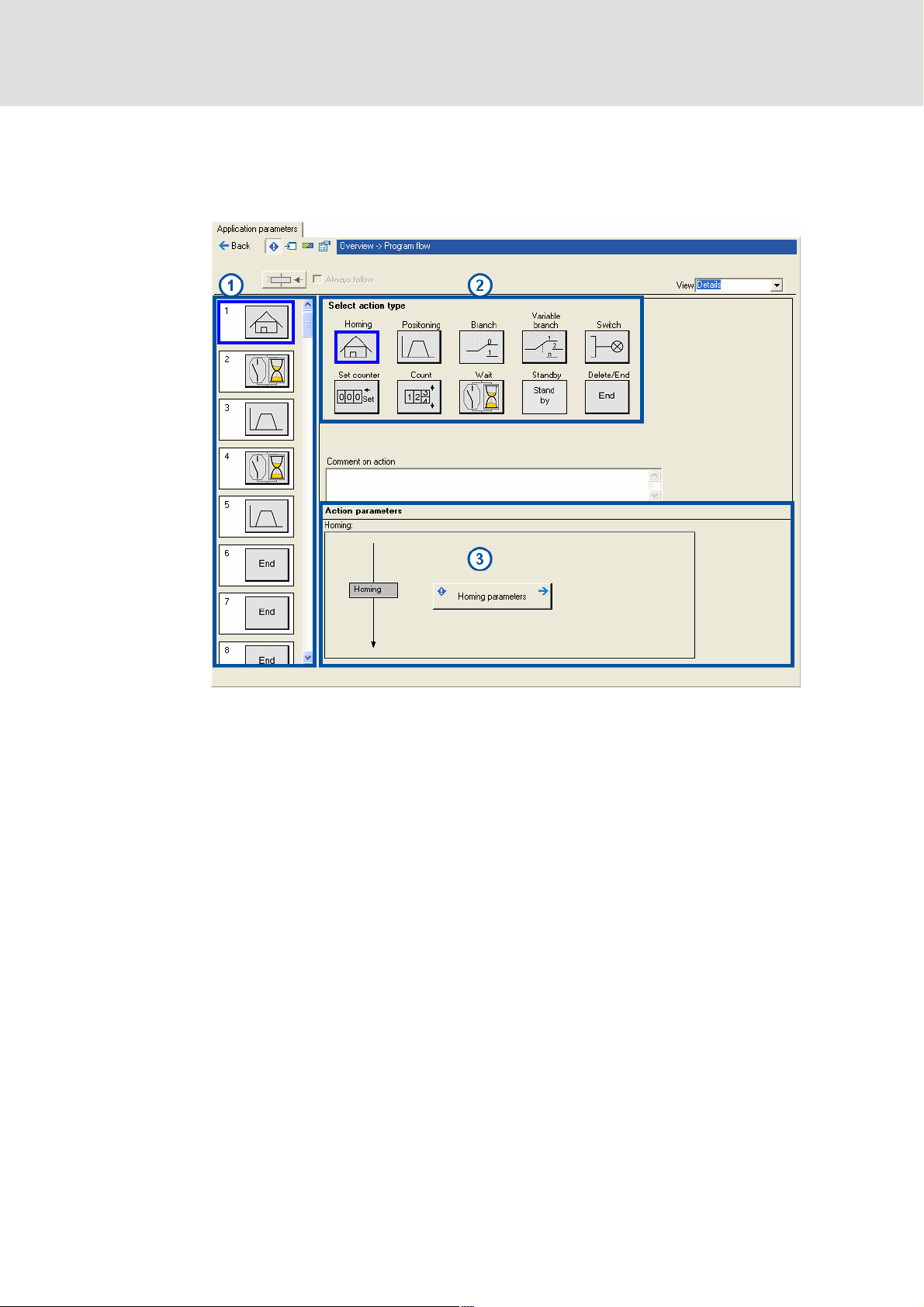
5.3.7 Parameter setting of the program flow in the Engineer
Go to the »Engineer« to the Application parameter tab and click Program flow in the
topmost dialog level to change to the dialog for the sequence table:
Basic procedure
In the default setting the sequence table contains a small "Positioning program", which
first rotates the axis 360° clockwise and afterwards 360° counter-clockwise.
Proceed as follows to define the desired program flow:
1. Select the program step (1 .... 100) to be edited on the left in the sequence table.
2. Select the action type for the selected program step by clicking it.
3. If the selected action type provides more than one action, select the action to be
parameterised from the list field Selection of action number.
– The next free action is suggested automatically.
4. Enter a comment about the action (optional).
5. Set parameters of the action.
– If required, call the corresponding subsequent dialogs.
6. Repeat step 1 ... 5 until all actions required for the program flow are parameterised.
42 L EDS94TA10060xxxx EN 1.2 - 03/2010
Page 43

9400 Technology applications | Positioning sequence control
5.3.8 Control of the sequence table
A LOW/HIGH edge at the digital input DI6 starts the parameterised program flow if the
controller is enabled and no error is pending.
The first step set in C03000 of the sequence table is executed.
By setting the digital input DI7 to HIGH level, the program flow can be stopped, if
required (break).
Note!
In the following cases the program flow is interrupted:
• The controller inhibit is activated.
• Quick stop is activated.
• The drive interface changes to an error status.
If the controller is not inhibited, a shutdown of the drive via the basic function
"Quick stop" is effected.
Parameter setting & configuration
Program flow
After the interruption is deactivated again (e.g. because an activated quick stop
has been deactivated again), a renewed LOW/HIGH edge is required at the
digital input DI6 in order that the positioning program can be continued with
the sequence step.
Parameter setting: Tab Application parameters dialog level Overview L_Sequencer
Parameter Lenze setting
Value Unit
C03000 First step 1
C04504 Jump destination 0
Control inputs of the function Signal configuration
Lenze setting Control input (Multiplexer parameters)
C03000 First step C03079/6
DIGIN 6 Sequencer start C03070/1
DIGIN 7 Sequencer break C03070/2
FALSE Sequencer jump C03070/3
FALSE Sequencer abort C03070/4
FALSE Sequencer interruption C03070/5
Controller inhibit
Quick stop active
Error active
DIGIN 5 Reset program/error status C03070/8
Reset program status C03070/6
or
or
EDS94TA10060xxxx EN 1.2 - 03/2010 L 43
Page 44

9400 Technology applications | Positioning sequence control
Parameter setting & configuration
Profile data management
5.4 Profile data management
Positioning sequence control
Sequencer
PositionerTable
Profiles
Override
Enable
LS_Homing
LS_Positioner
n
LS_ManualJog
ç
n
Basic drive functions
n
0-100 100 200
t
LS_Quickstop
è
n
t
LS_Stop
internal
status machine
Status
machine
(basic drive
functions)
STOP
LS_Brake
t
M
LS_Limiter
n
t
t
[5-5] Profile data management (schematic diagram)
The profile data management serves to file and manage up to 75 (travel) profiles.
A profile describes a motion request which can be converted by the basic drive function
"Positioning" into a rotary motion.
To execute a profile, 50 actions of type "Positioning" are available for the sequence
table.
The profile data management also enables the "teaching" of speed, acceleration/
deceleration and S-ramp times. "Teach" function
( 52)
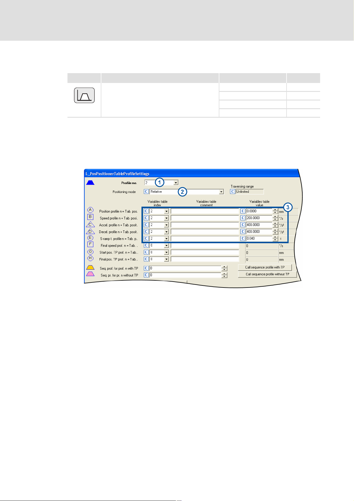
5.4.1 Profile parameters
A profile is described by the following profile parameters:
v [m/s]
B
C
F
E
[5-6] Profile parameters
v [m/s]
t [s]
B
C
E
F
E
E
A
D
E
E
TP window
G H
TP
E
A
D
E
t [s]
44 L EDS94TA10060xxxx EN 1.2 - 03/2010
Page 45

9400 Technology applications | Positioning sequence control
Symbol Profile parameters
(Standard) profile
Profile data set (profile no. 1 ... 75) in which the profile data are stored.
Mode
Selection of the positioning mode. Positioning modes
Position
A
Target position or path distance to be traversed.
The position is either indicated as absolute or relative position.
• An absolute position always specifies the distance to the zero position defined:
absolute position = target position
10
0
• A relative position indicates the distance to the starting position (current position):
Relative position = target position - starting position
10
Parameter setting & configuration
Profile data management
( 48)
30
P1
10 20 30 40 50 60 70 80 90 100
20 50
80
P2
P3
P3P2P1
10 20 30 40 50 60 70 80 90 100
0
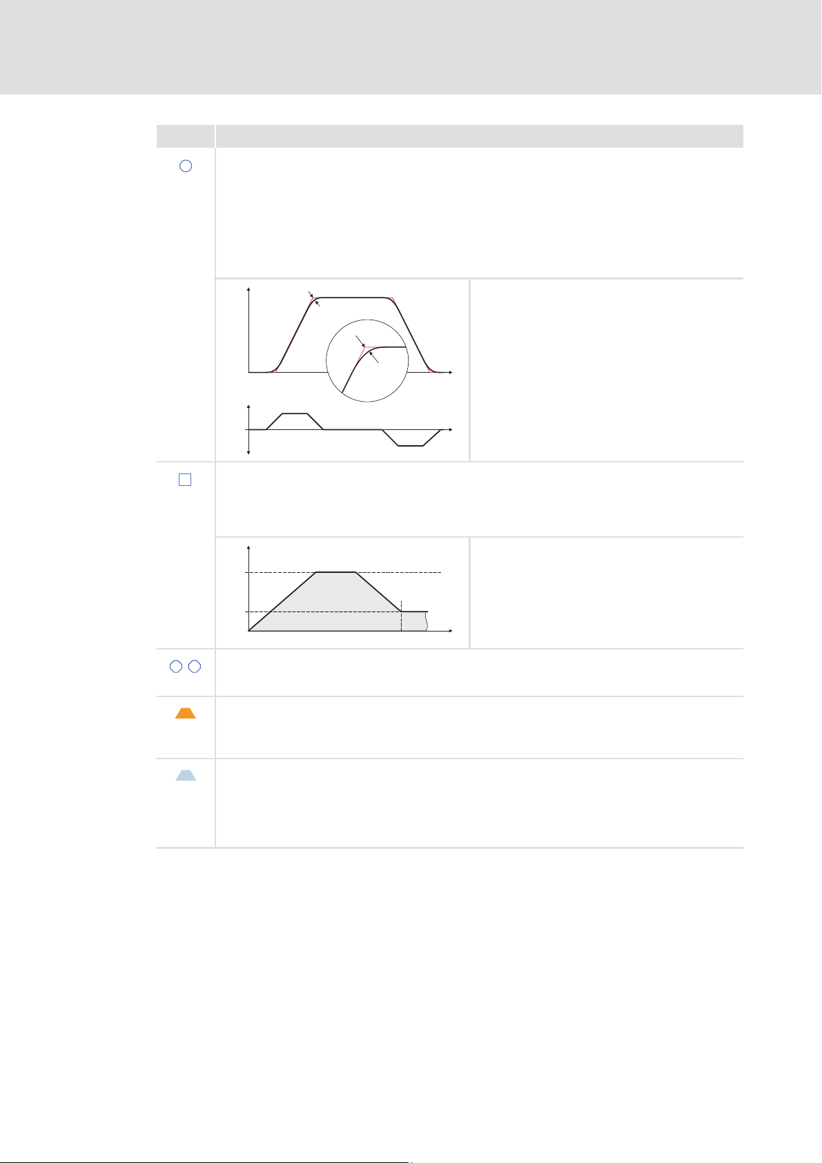
Speed
B
Maximum speed with which the target is to be approached.
• Depending on the profile parameter position, acceleration and deceleration, it is possible that the
drive may not reach the maximum speed. In this case, the graph would display a triangle instead of
a trapezium.
v [m/s]
v
pos
n Acceleration
o Travelling speed (is not reached here)
p Deceleration
q Target position (or feed distance)
t [s]
Acceleration
C
Selection of the change in speed by which acceleration is to be carried out maximally.
• The following two acceleration types are distinguished:
–Constant acceleration: the speed increases linearly.
–Linearly increasing acceleration: The speed increases in S-shapes.
v [m/s]
v
pos
n Constant acceleration
o Linearly increasing acceleration
v [m/s]
t [s]
v
pos
t [s]
Deceleration
D
Selection of the change in speed by means of which deceleration to standstill is to be maximally effected
again.
EDS94TA10060xxxx EN 1.2 - 03/2010 L 45
Page 46
9400 Technology applications | Positioning sequence control
Parameter setting & configuration
Profile data management
Symbol Profile parameters
S-ramp time
E
When the S-ramp time is selected for a profile, it is executed with S-shaped ramps, e.g. acceleration and
deceleration processes are started smoothly to reduce the jerk and thus prevent the drive components
from damage.
• The acceleration/deceleration specified in the profile are only reached after the defined S-ramp time
has elapsed.
• This type of acceleration/deceleration is required for e.g. sensitive machine parts with clearance.
• The slower acceleration increase with the S profile prolongs the positioning time compared to the
time optimal L profile.
v [m/s]
n without jerk limitation (L profile)
o with jerk limitation (S profile)
a
Final speed
F
Selection of the speed by which the drive is to start the next profile after reaching the target position.
t [s]
t [s]
"Velocity changeover" or "Overchange" can be implemented with a final speed that is non-zero, i.e.
when the target position is reached, a second positioning process is started immediately without the
drive being decelerated to standstill at the first target position:
v [m/s]
v
pos
n Target position
o Final speed (here unequal "0")
v
G H
end
Start of TP window / End of TP window
These profile parameters serve to restrict the range for a touch probe positioning (residual path
t [s]
positioning) in which touch probes are to be detected.
Sequence profile with TP
Profile data set (profile no. 1 ... 75) in which the profile data of the profile are stored which is to be
executed after a touch probe has been detected.
• For the setting "0" no further profile connection by touch probe is effected.
Sequence profile without TP
Profile data set (profile no. 1 ... 75) in which the profile data of the profile is stored which is to be
executed after the standard profile has been executed (profile chaining).
• With the setting "0" no profile chaining is carried out.
• The sequence profile defined in this profile parameter is executed even if no touch probe has been
detected within the defined TP window.
46 L EDS94TA10060xxxx EN 1.2 - 03/2010
Page 47

9400 Technology applications | Positioning sequence control
5.4.2 Variable tables
To simplify parameter handling, the four most important physical sizes for profile
parameters are stored in separate "variable tables".
Parameter setting & configuration
Profile data management
VTPOS
Positions
VTSPEED
Speeds
VTACC
Acceleration/
VTJERK
S-ramp times
deceleration
Unit unit unit/s unit/s
2
s
Data format DINT with four decimal positions
Memory locations75505050
Code C04711/1...75 C04712/1...50 C04713/1...50 C04714/1...50
For profile
parameters
Target position
TP window starting position
TP window end position
Speed
Final speed
Acceleration
Deceleration
S-ramp time
Note!
A value is assigned to a profile parameter by referring to a table position of the
assigned variable table.
• Hence, not the value itself is entered into the profile parameter but the index
of the table position which contains the value to be used.
• See the example in the illustration [5-7]
Profile 1
Mode
Position
Speed
Acceleration
Deceleration
Jerk time
End speed
TP window start position
TP window end position
Next TP profile
Next profile
3
3
1
1
2
1
50
6
7
12
2
VTPOS
VTACC
VTACC
VTJERK
VTPOS
VTPOS
. ( 47)
1
2
...
100
1
2
...
50
VTPOS
VTSPEED
200 [unit]/s
400 [unit]/s
50 [unit]/s
Mode
Position
Speed
Acceleration
Deceleration
Jerk time
End speed
TP window start position
TP window end position
Next TP profile
Next profile
Profile 2
4
4
2
1
3
1
50
6
8
13
5
VTPOS
VTACC
VTACC
VTJERK
VTPOS
VTPOS
VTACC
1
2
...
50
VTJERK
1
2
...
50
[5-7] Principle: References to variable tables (here: References to VTSPEED)
In case of several references to the same table position, a change of the value in this
table position affects several profiles at the same time. Thus, recurring profile
parameters only need to be changed on one position.
EDS94TA10060xxxx EN 1.2 - 03/2010 L 47
Page 48

9400 Technology applications | Positioning sequence control
Parameter setting & configuration
Profile data management
If e.g. in case of a profile linkage, several profiles are to be executed with the same
speed, the corresponding profile parameters "speed" can all refer to the same table
position.
For an easier assignment and identification of the entered values, each table position
can be optionally provided with a comment in the »Engineer«.
5.4.3 Positioning modes
Depending on the traversing range/application, you can select between different
positioning modes which are described in the below table.
Note!
For absolute positioning, the home position must be known!
• If an absolute positioning process (positioning modes 1 ... 2 and 11 ... 16) is
started although the home position is not known, an error message is
indicated.
– In this case a programming error has occurred and the program flow must
be reset.
– If the error only occurs in a sequence profile, the last valid deceleration is
used to decelerate the drive to standstill.
The modulo positioning modes may involve reversing processes!
• If a modulo positioning process (positioning modes 11 ... 16) is started at an
initial speed other than zero, the target position may be overtravelled and a
reversing process may follow, depending on the selected deceleration / Sramp time parameters. This would also cause e.g. counter-clockwise rotation
in the "Absolute CW (modulo)" positioning mode.
Positioning mode
1 Absolute
The axis travels to an absolute position.
• Reference for the absolute position is zero position.
• The home position must be known.
• The traversing range is limited:
–to 214748.3647 [unit]
–by the internal display area (±2
• Not possible with "modulo" traversing range.
2 Absolute TP
Like mode 1, but with profile change when a touch probe is detected.
Touch probe positioning
5 Relative
The axis is traversed by a distance.
• Reference for the distance is the target position of the profile executed before.
• The feed per positioning is limited:
–to 214748.3647 [unit]
–by the internal display area (±2
6 Relative TP
Like mode 5, but with profile change on touch probe detection.
Touch probe positioning
. ( 51)
. ( 51)
31
increments)
31
increments)
48 L EDS94TA10060xxxx EN 1.2 - 03/2010
Page 49

9400 Technology applications | Positioning sequence control
Parameter setting & configuration
Profile data management
Positioning mode
7 Speed
Continuous constant travel.
• Only possible with "unlimited" and "limited" traversing range
• This mode does not approach a defined position, but follows the profile.
• Acceleration and deceleration are based on profile values.
• The traversing direction is defined by the sign of the traversing speed.
• Stopped through break signal.
8 Speed TP
Like mode 7, but with profile change on touch probe detection.
Touch probe positioning
11 Absolute CW
The axis travels in CW direction to an absolute position.
• Only possible with "Modulo" traversing range.
• Reference for the absolute position is zero position.
• In this direction the zero position of the axis can be overtravelled.
12 Absolute CW TP
Like mode 11, but with profile change on touch probe detection.
Touch probe positioning
13 Absolute CCW
The axis travels in CCW direction to an absolute position.
• Only possible with "Modulo" traversing range.
• Reference for the absolute position is zero position.
• In this direction the zero position of the axis can be overtravelled.
14 Absolute CCW TP
Like mode 13, but with profile change when a touch probe is detected.
Touch probe positioning
15 Absolute ShortestWay
The axis travels to an absolute position in best time.
• Only possible with "Modulo" traversing range.
• Reference for the absolute position is zero position.
• The rotary table positioning is basically an absolute positioning with target positions between 0 and 360
angular degree [°]. In this mode the zero point can also be overtravelled if this is the shortest way to the
target position:
. ( 51)
. ( 51)
. ( 51)
360°/0°
300°
240°
180°
16 Absolute ShortestWay TP
Like mode 15, but with profile change on touch probe detection.
Touch probe positioning
. ( 51)
60°
120°
EDS94TA10060xxxx EN 1.2 - 03/2010 L 49
Page 50

9400 Technology applications | Positioning sequence control
Parameter setting & configuration
Profile data management
5.4.4 Positioning with final speed
If a positioning process with a final speed other than zero is carried out, a velocity
changeover / overchange can be realised, i.e. a second positioning process is started
immediately once the target position is reached, and the drive does not come to a standstill
at the first target position.
v [m/s]
v
pos
v
end
[5-8] The principle of velocity changeover / overchange
t [s]
n Target position
o Final speed (here unequal "0")
Normally, the drive has reached the final speed when the target position is reached.
The profile is run through which is defined via "Profile data sequence profile without
TP".
The final speed must not exceed the maximum profile speed.
– The speed is internally limited to the profile speed.
– This is the maximum value for the final speed if the profile speed is reduced via
override. (This behaviour may add to the cases described in the note below.)
– The speed limitation is not affected by subsequent increases in the override value.
Note!
Positioning processes with final speeds other than zero do not permit reversing.
In this case, the positioning process is aborted and an error is issued.
In the case of positioning processes with final speeds and if S-shaped ramps are
used, a plausibility check as to whether the final speed can be reached is carried
out when the profile is started. If the final speed cannot be reached, the
positioning process is aborted and an error is issued. This is often the case if the
positioning process has been paused and is then to be continued.
50 L EDS94TA10060xxxx EN 1.2 - 03/2010
Page 51

9400 Technology applications | Positioning sequence control
5.4.5 Touch probe positioning
In the touch probe positioning mode, the profile is first executed according to the Profile
parameters set. If a touch probe is detected during the process, it is automatically changed
to the profile specified in the profile parameter "Sequence profile with TP".
Here the current actual position is stored at the time of the touch probe activation (by
a touch probe sensor).
In the following relative positioning process, the "residual path" to this stored position
is travelled according to the increments.
Parameter setting & configuration
Profile data management
v [m/s]
Profile 4 Profile 7
Touch probe
v [m/s]
Profile 4 Profile 7
n "Starting profile"
o "Residual path profile" that is defined in the profile parameter "Sequence profile with TP" of the starting profile.
[5-9] Examples for a "residual path positioning" after a touch probe is detected
Touch probe
t [s]
t [s]
The profile parameters "TP window start" and "TP window end" the range in which
touch probes are to be detected can be restricted.
– If both profile parameters are "0", touch probe detection will be active over the whole
profile/the whole traversing range.
If no touch probe is detected and after the profile is executed, the positioning is
continued with the profile defined in the profile parameter "Sequence profile without
TP" (profile chaining).
Mode
Position
Speed
Next TP profile
Next profile
Profile 4
...
7
Mode
Position
Speed
Next TP profile
Next profile
Profile 7
...
Note!
If a profile is travelled with high speed and a touch probe positioning is started
the residual path of which is shorter than the result from current speed and set
deceleration ramp, the target position is "overtravelled".
• Normally a reversing movement occurs, i.e. the drive returns.
• If, for instance, a CCW rotation of the drive is forbidden by the safety module,
the target cannot be approached since in this case the reversing movement is
not permissible.
Further constellations are possible in connection with profile chaining in which
an approach of the target position is impossible.
EDS94TA10060xxxx EN 1.2 - 03/2010 L 51
Page 52

9400 Technology applications | Positioning sequence control
Parameter setting & configuration
Profile data management
5.4.6 "Teach" function
The "Teach" function of the profile data management enables the teaching of positions,
speeds, accelerations and S-ramp times.
The basic function "Manual jog" serves, for instance to approach the desired position
manually and transmits it via "Teaching" to the variable table for positions.
Parameter setting: Tab Application parameters dialog level Overview
L_PositionerTable
Control/setpoint inputs of the function Signal configuration
Lenze setting Control/setpoint input (Multiplexer parameters)
FALSE Teach position C03020/1
C03016 Selection of table position for position C03029/1
Zero position Teach position C03125/1
FALSE Teach speed C03020/2
C03017 Selection of table position for speed C03029/2
Speed setpoint Teach speed C03024/1
FALSE Teach acceleration C03020/3
C03018 Selection of table position for acceleration C03029/3
0 Teach acceleration C03027
FALSE Teach S-ramp time C03020/4
C03019 Selection of table position for S-ramp time C03029/4
0 Teach S-ramp time C03028
Note!
After the function block editor is enabled the "Teach" function must be
configured directly in the FB interconnection instead of via the parameters
mentioned before!
52 L EDS94TA10060xxxx EN 1.2 - 03/2010
Page 53

9400 Technology applications | Positioning sequence control
5.5 Speed/acceleration override
Parameter setting & configuration
Speed/acceleration override
Positioning sequence control
Sequencer
Speed override
Acceleration override
AIN1
AIN2
PositionerTable
Profiles
Override
Enable
LS_Homing
LS_Positioner
n
LS_ManualJog
ç
n
Basic drive functions
n
0-100 100 200
t
LS_Quickstop
è
n
t
LS_Stop
internal
status machine
Status
machine
(basic drive
functions)
STOP
LS_Brake
t
M
LS_Limiter
n
t
t
[5-10] Speed/acceleration override (schematic diagram)
"Override" is the change of profile parameters and their acceptance during the positioning
process.
In this case, the travel profile is adapted accordingly to ensure that the defined target
position is still exactly approached if, for example, the speed is changed during the
positioning process ("speed override"):
v [m/s]
Dt
n The speed is reduced during the positioning
process.
o To reach the defined position, the missing
surface must be "attached" to the profile.
p When the speed is reduced the positioning
t [s]
process takes a longer time (Δt).
[5-11] Override (here: Speed override)
Parameter setting: Tab Application parameters dialog level Overview LS_Positioner
Control/setpoint inputs of the function Signal configuration
Lenze setting Control/setpoint input (Multiplexer parameters)
C03013 Activate override C03185/5
AIN 1 Speed override C03186/1
AIN 2 Acceleration override C03186/2
+100 % Deceleration override C03186/3
EDS94TA10060xxxx EN 1.2 - 03/2010 L 53
Page 54

9400 Technology applications | Positioning sequence control
Parameter setting & configuration
Following error monitoring
5.6 Following error monitoring
j
In the Lenze setting a two-stage following error monitoring is
active.
If the parameterisable switching threshold 1 is exceeded, a
n Switching threshold
o Hysteresis
[5-12] Following error monitoring
warning appears. If the higher-set switching threshold 2 is
exceeded, a "warning locked" appears.
Parameter setting: Tab Application parameters dialog level Overview Following
error
Parameter Lenze setting
Value Unit
C03911 Switching threshold 1 100.0000 unit
C03914 Switching threshold 2 200.0000 unit
C03917 Hysteresis 1 0.0000 unit
C03920 Hysteresis 2 0.0000 unit
C05902/1 Error response - following error 1 Warning
C05902/2 Error response - following error 2 Warning locked
Control inputs of the function Signal configuration
Lenze setting Control input (Multiplexer parameters)
TRUE Activate following error limit 1 C03058/1
TRUE Activate following error limit 2 C03058/2
54 L EDS94TA10060xxxx EN 1.2 - 03/2010
Page 55

5.7 Manual jog
9400 Technology applications | Positioning sequence control
Parameter setting & configuration
Manual jog
Basic drive functions
LS_Homing
0-100 100 200
LS_Positioner
n
LS_ManualJog
è
ç
n
t
t
LS_Stop
internal
n
status machine
Status
machine
(basic drive
functions)
LS_Quickstop
n
STOP
LS_Brake
t
M
LS_Limiter
n
t
[5-13] Basic function "Manual jog" (schematic diagram)
Parameter setting: Tab Application parameters dialog level Overview Manual jog
Parameter Lenze setting
C02620 Manual jog: Speed 1 360.0000 unit/s
C02621 Manual jog: Speed 2 720.0000 unit/s
C02622 Manual jog: Acceleration 360.0000 unit/s
C02623 Manual jog: Deceleration 1440.0000 unit/s
C02624 Manual jog: S-ramp time 0.100 s
C03007 Activate positive manual jog FALSE
C03008 Activate negative manual jog FALSE
C03009 Activate "Retract limit switch" FALSE
For the setting-up operation and
"Teaching" of positions the basic function
"Manual jog" is available.
Manual jog is controlled via parameters
(e. g. via HMI).
Manual jog can always be carried out if the
sequence control is not active and no other
basic function and no error status are
active. The request of manual jog then is
effected automatically with the travel
commands.
t
Value Unit
2
2
Control inputs of the function Signal configuration
Lenze setting Control input (Multiplexer parameters)
Automatic
Request manual jog C03155/1
activation
C03007 Activate positive manual jog C03155/2
C03008 Activate negative manual jog C03155/3
FALSE Activate 2. speed C03155/4
C03009 Activate "Retract limit switch" C03155/5
+100 % Manual jog override C03186/5
EDS94TA10060xxxx EN 1.2 - 03/2010 L 55
Page 56

9400 Technology applications | Positioning sequence control
Parameter setting & configuration
Quick stop
5.8 Quick stop
The basic function "Quick stop" brakes the
drive to standstill within the deceleration
time set for the quick stop function after a
LS_Homing
Basic drive functions
LS_Stop
internal
n
status machine
LS_Brake
corresponding request independent of the
0-100 100 200
t
setpoint selection. The sequence control is
interrupted.
LS_Positioner
n
LS_ManualJog
è
ç
n
[5-14] Basic function "Quick stop" (schematic diagram)
t
t
Status
machine
(basic drive
functions)
DI1
LS_Quickstop
n
STOP
M
LS_Limiter
n
t
t
If the quick stop is deactivated, the drive
remains in standstill until the sequence
control is started again and takes over the
drive control.
The quick stop function can be activated as follows in the Lenze setting:
– By setting the digital input DI1 to LOW level.
– By a master control via the port LPortControl:
By setting bit 2 of the bit-coded control word 1.
Parameter setting: Tab Application parameters dialog level Overview All basic
functions Quick stop
Parameter Lenze setting
Value Unit
C00105 Deceleration time "quick stop" 0.000 s
C00106 S-ramp time "quick stop" 0.00 %
C00107 Reference for quick stop deceleration time Motor reference speed (C00011)
Control inputs of the function Signal configuration
Lenze setting Control input (Multiplexer parameters)
DIGIN 1 Activate quick stop 1 C03135/1
Control word 1
Activate quick stop 2 C03135/2
bit 02
FALSE Activate quick stop 3 C03135/3
56 L EDS94TA10060xxxx EN 1.2 - 03/2010
Page 57

5.9 Limiter
9400 Technology applications | Positioning sequence control
Parameter setting & configuration
Limiter
Status
machine
(basic drive
functions)
[5-15] Basic function "Limiter" (schematic diagram)
M
LS_Limiter
n
DI4
DI3
t
The software limit positions which can be set via parameters serve to limit the travel
range by means of software and prevent that travel commands are executed which
would cause an exit of the permissible travel range.
Moreover, the travel range limits are monitored via limit switches via the digital inputs
DI3 and DI4.
Note!
The digital inputs DI3 and DI4 are configured fail-safe in C00114/3 and C00114/
4 , i.e. a HIGH level is expected at both inputs in idle state.
• If the travel range limits should not be monitored (e.g. in case of a rotary axis),
set the limit switch inputs of the basic function "Limiter" permanently to
FALSE.
The basic function "Limiter" monitors the
travel range limits via limit switches and
parameterisable software limit positions
and after an according request from the
safety module can lead the drive into
defined limit ranges. Furthermore higherlevel limit values for travel profiles can be
entered and activated.
The parameterised limit values for travel profiles are not effective for the basic
functions "speed follower", "torque follower", and "position follower"!
• For the exceeding of the limit values an error response can be set.
Parameter setting: Tab Application parameters dialog level Overview Limiter
Parameter Lenze setting
Value Unit
Limit values
C02707 Permissible direction of rotation Positive and negative
C02700 Software limit positions are active Deactivated
C02701/1 Positive software limit position 0.0000 unit
C02701/2 Negative software limit position 0.0000 unit
Only for homing, positioning and manual jog
C02702 Limitations are active Deactivated
C02703 Max. speed 3600.0000 unit/s
C02705 Max. acceleration 3600.0000 unit/s
C02706 Min. S-ramp time 100 ms
2
EDS94TA10060xxxx EN 1.2 - 03/2010 L 57
Page 58

9400 Technology applications | Positioning sequence control
Parameter setting & configuration
Limiter
Parameter Lenze setting
For manual jog only
C02713 Max. manual jog distance 360.0000 unit
Limited speed 1 ... 4 (only for homing, positioning, and manual jog)
C02708/1 Limited speed 1 3600.0000 unit/s
C02710/1 Delay lim. speed 1 0.0100 unit/s
C02711/1 S-ramp time lim. speed 1 100 ms
C02708/2 Limited speed 2 7200.0000 unit/s
C02710/2 Delay lim. speed 2 0.0100 unit/s
C02711/2 S-ramp time lim. speed 2 100 ms
C02708/3 Limited speed 3 14400.0000 unit/s
C02710/3 Delay lim. speed 3 0.0100 unit/s
C02711/3 S-ramp time lim. speed 3 100 ms
C02708/4 Limited speed 4 28800.0000 unit/s
C02710/4 Delay lim. speed 4 0.0100 unit/s
C02711/4 S-ramp time lim. speed 4 100 ms
Value Unit
2
2
2
2
Control inputs of the function Signal configuration
Lenze setting Control input (Multiplexer parameters)
DIGIN 3 Positive limit switch C03150/1
DIGIN 4 Negative limit switch C03150/2
58 L EDS94TA10060xxxx EN 1.2 - 03/2010
Page 59

5.10 Brake control
9400 Technology applications | Positioning sequence control
Parameter setting & configuration
Brake control
LS_Brake
The basic function "Brake control" serves
to the wear free control and monitoring of
a holding brake.
In the simplest case, an optionally
available brake module is used.
Status
machine
(basic drive
functions)
M
Alternatively the holding brake can also be
controlled and monitored via the digital
inputs/outputs.
[5-16] Basic function "Brake control" (schematic diagram)
Note!
In the Lenze setting the brake control is switched off to reach a safe state after
mains connection.
If the automatic operation (operating mode 2 or 12) is selected in C02580, the brake is
controlled automatically, i.e. if the multi-purpose positioning or another basic function is
activated which causes the drive to traverse, the brake is opened automatically and the
operation is enabled.
Parameter setting: Tab Application parameters dialog level Overview Brake control
Parameter Lenze setting
Value Unit
C02580 Operating mode of brake Brake control off
C02581 Threshold for brake activation 50 rpm
C02582 Brake resp. to pulse inhibit Activate brake immediately
C02583 Status input monitoring Not active
C02585 Brake control polarity Not inverted
C02586 Starting torque 1 0.00 Nm
C02587 Starting torque 2 0.00 Nm
C02588 Starting torque source Starting torque 1/2
C02589 Brake closing time 100 ms
C02590 Brake opening time 100 ms
C02591 Waiting time - status monitoring 100 ms
C02593 Waiting time - brake activation 0.000 s
C02594 Test torque 0.00 Nm
C02595 Permissible angle of rotation 5 °
C02596 Grinding speed 100 rpm
C02597 Accel./decel. time - grinding 1.000 s
C02598 Grinding ON time 0.5 s
C02599 Grinding OFF time 0.5 s
EDS94TA10060xxxx EN 1.2 - 03/2010 L 59
Page 60

9400 Technology applications | Positioning sequence control
Parameter setting & configuration
Brake control
Control/setpoint inputs of the function Signal configuration
Lenze setting Control/setpoint input (Multiplexer parameters)
FALSE Open brake (release) C03165/1
FALSE Activate starting torque 2 C03165/2
FALSE Keep open brake at standstill C03165/3
FALSE Brake status signal C03165/4
FALSE Activate brake test C03165/5
FALSE Grind brake C03165/6
0 % Additional torque C03166
60 L EDS94TA10060xxxx EN 1.2 - 03/2010
Page 61

9400 Technology applications | Positioning sequence control
5.11 Signal configuration
5.11.1 Drive and motor interface
If required, the preset signal configuration of the control and setpoint inputs of the drive
and motor interface can be easily reconfigured by parameterising the assigned multiplexer
parameters.
Drive interface
Signal (Lenze setting) Control input Signal configuration
DIGIN 5 Reset error 1 C03130/2
Parameter setting & configuration
Signal configuration
FALSE Set controller inhibit C03130/1
FALSE Reset error 2 C03130/3
FALSE Reset error 3 C03130/4
FALSE Set error C03130/5
FALSE Switch on drive C03130/6
Motor interface
Signal (Lenze setting) Setpoint input Signal configuration
100 % Position controller adaptation C03141/1
100 % Phase controller adaptation C03141/2
100 % Speed controller adaptation C03141/3
100 % Upper torque limit value C03141/4
-100 % Lower torque limit value C03141/5
100 % Flux setpoint C03141/6
100 % Adaptation of mass inertia C03141/7
EDS94TA10060xxxx EN 1.2 - 03/2010 L 61
Page 62

9400 Technology applications | Positioning sequence control
Parameter setting & configuration
Signal configuration
5.11.2 Output ports
If required, the preset signal configuration of the output ports can be easily reconfigured
by parameterising the assigned multiplexer parameters.
Output port "LPortAxisOut1"
The output port LPortAxisOut1 is intended for the connection with a following axis.
Signal (Lenze setting) Output port Signal configuration
Axis status word
• The bit assignment is identical to that of status word 1/2.
• Application-specific signals can be supplemented.
Drive ready Axis status word bit 00 C03120/1
FALSE Axis status word bit 01 C03120/2
Operation enabled Axis status word bit 02 C03120/3
Error active Axis status word bit 03 C03120/4
FALSE Axis status word bit 04 C03120/5
Quick stop active Axis status word bit 05 C03120/6
Drive is ready to start Axis status word bit 06 C03120/7
Warning active Axis status word bit 07 C03120/8
FALSE Axis status word bit 08 C03120/9
FALSE Axis status word bit 09 C03120/10
FALSE Axis status word bit 10 C03120/11
Motor control in limitation Axis status word bit 11 C03120/12
Sequence control ready to start Axis status word bit 12 C03120/13
Sequence control started Axis status word bit 13 C03120/14
Sequence control reset Axis status word bit 14 C03120/15
Sequence control processed Axis status word bit 15 C03120/16
Setpoints for horizontal communication
Filtered torque setpoint Axis-Port Out 1 C03124/1
Scaling:
16384 ≡ 2
Motor speed Axis port out 2 C03124/2
Scaling:
1073741824 ≡ 2
14
≡ 100 % motor reference torque (C00057/2)
30
≡ 100 % motor reference speed (C00011)
62 L EDS94TA10060xxxx EN 1.2 - 03/2010
Page 63

9400 Technology applications | Positioning sequence control
Parameter setting & configuration
Signal configuration
Output port "LPortStatus1"
The output port LPortStatus1 is intended for the connection with a higher-level control.
Signal (Lenze setting) Output port Signal configuration
Status word 1
Drive ready Status word 1 bit 00 C03121/1
FALSE Status word 1 bit 01 C03121/2
Operation enabled Status word 1 bit 02 C03121/3
Error active Status word 1 bit 03 C03121/4
FALSE Status word 1 bit 04 C03121/5
Quick stop active Status word 1 bit 05 C03121/6
Drive is ready to start Status word 1 bit 06 C03121/7
Warning active Status word 1 bit 07 C03121/8
FALSE Status word 1 bit 08 C03121/9
FALSE Status word 1 bit 09 C03121/10
FALSE Status word 1 bit 10 C03121/11
Motor control in limitation Status word 1 bit 11 C03121/12
Sequence control ready to start Status word 1 bit 12 C03121/13
Sequence control started Status word bit 13 C03121/14
Sequence control reset Status word 1 bit 14 C03121/15
Sequence control processed Status word 1 bit 15 C03121/16
Output port "LPortStatus2"
Signal (Lenze setting) Output port Signal configuration
Status word 2
FALSE Status word 2 bit 00 C03122/1
FALSE Status word 2 bit 01 C03122/2
FALSE Status word 2 bit 02 C03122/3
FALSE Status word 2 bit 03 C03122/4
FALSE Status word 2 bit 04 C03122/5
FALSE Status word 2 bit 05 C03122/6
FALSE Status word 2 bit 06 C03122/7
FALSE Status word 2 bit 07 C03122/8
FALSE Status word 2 bit 08 C03122/9
FALSE Status word 2 bit 09 C03122/10
FALSE Status word 2 bit 10 C03122/11
FALSE Status word 2 bit 11 C03122/12
FALSE Status word 2 bit 12 C03122/13
FALSE Status word 2 bit 13 C03122/14
FALSE Status word 2 bit 14 C03122/15
FALSE Status word 2 bit 15 C03122/16
EDS94TA10060xxxx EN 1.2 - 03/2010 L 63
Page 64

9400 Technology applications | Positioning sequence control
Parameter setting & configuration
Actual value and status signals
5.12 Actual value and status signals
The following tables contain the Lenze assignment of the analog and digital outputs for
the "Positioning sequence control" technology application.
The default signal configuration if required can be easily changed by parameterising
the multiplexer parameters assigned.
Analog outputs
Terminal X3 Signal (Lenze setting) Signal configuration
AO1 Motor speed
GA
AO1
AO2
• Scaling: ±10 V ≡ motor reference speed (C00011)
AO2 Motor torque (setpoint)
• Scaling: 10 V ≡ Motor reference torque (C00057/2)
C03110/1
C03110/2
Digital outputs
Terminal X4 Signal (Lenze setting) Signal configuration
DO1 Status "Drive ready"
GO
24O
DO1
DO2
DO3
DO4
• DC-bus voltage is available and no error has occurred.
DO2 Status "Positioner active" C03100/2
DO3 Status "Limitation active"
• At the moment a setpoint is limited or a software or hardware
limit switch has been reached.
DO4 Status "Error active acknowledgement is required"
• A monitoring function with the error response "Error" or "Quick
C03100/1
C03100/3
C03100/4
stop by trouble" has been activated and the controller is in the
status "Error active" or "Quick stop by trouble active".
Statebus
Terminal X2 Signal (Lenze setting) Signal configuration
GE
24E
SB
SB Status "Error active acknowledgement is required"
• A monitoring function with the error response "Error" or "Quick
stop by trouble" has been activated and the controller is in the
status "Error active" or "Quick stop by trouble active".
• The state bus is put in the "error" status.
C03100/5
Display elements
User LED Signal (Lenze setting) Signal configuration
"Positioning sequence control active" status C03100/6
64 L EDS94TA10060xxxx EN 1.2 - 03/2010
Page 65

9400 Technology applications | Positioning sequence control
5.13 Application error messages
For the output of application-specific error messages, the FB instances ApplicationError1
and ApplicationError2 of the function block L_DevApplErr are available in the network.
Via the boolean inputs up to 16 different application error messages with
parameterisable module ID, error ID and error response can be released by the
application.
Error message Error ID Error response
FB instance "ApplicationError1"
1 Following error limit 1 8001 Warning
2 Following error limit 2 8002 Warning locked
3 Positioner: Home position is not known 8003 Warning
4 Positioner: Cycle is not known 8004 Warning
5 Positioner: Wrong positioning mode 8005 Warning
6 Positioner: Invalid change of the positioning mode 8006 Warning
7 Positioner: Profile data is not plausible or faulty 8007 Warning
8 Positioner: Error in profile generation 8008 Warning
FB instance "ApplicationError2"
1 Free error message 1 8011 Information
2 Free fault message 2 8012 Information
3 PositionerTable: Invalid axis data structure 8013 Warning
4 PositionerTable: Invalid profile no. 8014 Information
5 PositionerTable: Invalid table no. 8015 Warning
6 Watch-Dog 8016 Quick stop by trouble
7 Sequencer: Error due to variable branch 8017 Warning
8 Sequencer: Pause 8018 Information
Parameter setting & configuration
Application error messages
Parameter setting: Tab All parameters
Parameter Lenze setting
FB instance "ApplicationError1"
C05900 Function block ID 999
C05901/1...8 Error ID 1 ... 8 See table above
C05902/1...8 Error response 1 ... 8 See table above
FB instance "ApplicationError2"
C05903 Function block ID 998
C05904/1...8 Error ID 1 ... 8 See table above
C05905/1...8 Error response 1 ... 8 See table above
Reset of error message
In the Lenze setting the digital input DI5 for resetting (acknowledging) an error message is
connected to the input DI_bResetError1 of the drive interface.
EDS94TA10060xxxx EN 1.2 - 03/2010 L 65
Page 66

9400 Technology applications | Positioning sequence control
Parameter setting & configuration
Parameterisable function blocks
5.14 Parameterisable function blocks
This subchapter lists all relevant parameterisable function blocks of the technology
application and the corresponding parameters in alphabetical order.
5.14.1 ActualSpeedScaling
Is an instance of Function
L_TbNormalize Scaling of actual speed to a parameterisable reference variable
Parameter Possible settings Information
C04036 -2147483647 2147483647 Reference variable
• Setting "0" is not possible.
• Initialisation: 44739243
5.14.2 ApplicationError1
Is an instance of Function
L_DevApplErr Error handling
Parameter Possible settings Information
C05900 980 999 Module ID
C05901/1...8 0 65535 Error ID
C05902/1...8 Error response
Application error messages
0None
1Fault
2Trouble
3 Quick stop by trouble
4 Warning locked
5 Warning
6Information
( 65)
• Initialisation: 999
• Initialisation: 8001 ... 8008
66 L EDS94TA10060xxxx EN 1.2 - 03/2010
Page 67

9400 Technology applications | Positioning sequence control
5.14.3 ApplicationError2
Is an instance of Function
L_DevApplErr Error handling
Parameter Possible settings Information
C05903 980 999 Module ID
C05904/1...8 0 65535 Error ID
C05905/1...8 Error response
Application error messages
0None
1Fault
2Trouble
3 Quick stop by trouble
4 Warning locked
5 Warning
6Information
Parameter setting & configuration
Parameterisable function blocks
( 65)
• Initialisation: 998
• Initialisation: 8011 ... 8018
5.14.4 FollowingErrorScaling
Is an instance of Function
L_TbNormalize Scaling of the following error to a parameterisable reference variable
Parameter Possible settings Information
C04035 -2147483647 2147483647 Reference variable
5.14.5 HysteresisFollowingError1
Is an instance of Function
L_SdSetPosition Conversion of the following error hysteresis 1 selected in the real units of the
machine via C03917 into a position in [increments].
Following error monitoring
Parameter Possible settings Information
C03917 -214000.0000 unit 214000.0000 Position value
C03918 String of digits Position unit
C03919 -2147483647 2147483647 State
• Setting "0" is not possible.
• Initialisation: 65536
( 54)
• Initialisation: 0.0000 unit
•Read only
•Read only
EDS94TA10060xxxx EN 1.2 - 03/2010 L 67
Page 68

9400 Technology applications | Positioning sequence control
Parameter setting & configuration
Parameterisable function blocks
5.14.6 HysteresisFollowingError2
Is an instance of Function
L_SdSetPosition Conversion of the following error hysteresis 2 selected in the real units of the
Parameter Possible settings Information
C03920 -214000.0000 unit 214000.0000 Position value
C03921 String of digits Position unit
C03922 -2147483647 2147483647 State
5.14.7 L_PosPositionerTable1
machine via C03920 into a position in [increments].
Following error monitoring
( 54)
• Initialisation: 0.0000 unit
•Read only
•Read only
Is an instance of Function
L_PosPositionerTable Profile data management
Parameter Possible settings Information
C04700/1 Teach position
C04700/2 Teach speed
C04700/3 Teach acceleration
C04700/4 Teach S-ramp time
C04701/1...75 -214748.3648 unit 214748.3648 VTPOS: variable positions
C04702/1...50 -214748.3648 unit/s 214748.3648 VTSPEED: variable speeds
C04703/1...50 -214748.3648 unit/s
0Ê1 The position applied at the input
dnPos_p is saved to the VTPOS table
position selected via the input
dwPosTableNumber.
0Ê1 The speed applied at the input
dnSpeed_s is saved to the VTSPEED
table position selected via the input
dwSpeedTableNumber.
0Ê1 The acceleration/deceleration
applied at the input dnAcc_s is saved
to the VTACC table position selected
via the input dwAccTableNumber.
0Ê1 The S-ramp time applied at the
input dwJerk is saved to the VTJERK
table position selected via the input
dwJerkTableNumber.
( 44)
• For execution via parameter
channel.
• For execution via parameter
channel.
• For execution via parameter
channel.
• For execution via parameter
channel.
• For selecting the target positions
and TP window start and end
positions for the profiles.
• For selecting the traversing and
final speeds for the profiles.
2
214748.3648 VTACC: variable accelerations
• For selecting the accelerations
and decelerations for the profiles.
68 L EDS94TA10060xxxx EN 1.2 - 03/2010
Page 69

9400 Technology applications | Positioning sequence control
Parameter setting & configuration
Parameterisable function blocks
Parameter Possible settings Information
C04704/1...50 -2147483.648 s 2147483.648 VTJERK: variable S-ramp times
• For selecting the S-ramp times for
the profiles.
C04705/1 DIS:bPosTeach
0FALSE
1TRUE
C04705/2 DIS:bSpeedTeach
0FALSE
1TRUE
C04705/3 DIS:bAccTeach
0FALSE
1TRUE
C04705/4 DIS:bJerkTeach
0FALSE
1TRUE
C04706/1 0 100 DIS:VTPosNum
C04706/2 0 100 DIS:VTSpeedNum
C04706/3 0 100 DIS:VTAccNum
C04706/4 0 100 DIS:VTJerkNum
C04706/5 0 100 DIS:ProfileNum
C04707/1 -214748.3648 unit 214748.3648 DIS:dnTeachPos
C04707/2 -214748.3648 unit/s 214748.3648 DIS:dnTeachSpeed
C04707/1 -214748.3648 unit/s
C04707/1 -214748.3648 s 214748.3648 DIS:dnTeachJerk
C04708 -2147483647 2147483647 State
2
214748.3648 DIS:dnTeachAcc
• Display of the input signal
bPosTeach.
• Display of the input signal
bSpeedTeach.
• Display of the input signal
bAccTeach.
• Display of the input signal
bJerkTeach.
• Display of the input signal
dwPosTableNumber.
• Display of the input signal
dwSpeedTableNumber.
• Display of the input signal
dwAccTableNumber.
• Display of the input signal
dwJerkTableNumber.
• Display of the input signal
dwProfileNumber.
• Display of the input signal
dnPos_p in the real unit of the
machine.
• Display of the input signal
dnSpeed_s in the real unit of the
machine.
• Display of the input signal
dnAcc_x in the real unit of the
machine.
• Display of the input signal dwJerk
in the real unit of the machine.
• Display of the bit-coded output
signal dnState.
EDS94TA10060xxxx EN 1.2 - 03/2010 L 69
Page 70

9400 Technology applications | Positioning sequence control
Parameter setting & configuration
Parameterisable function blocks
Parameter Possible settings Information
C04710/1...75
(subcode 1 ... 75 ≡ profile no. 1 ... 75)
C04711/1...75
(subcode 1 ... 75 ≡ profile no. 1 ... 75)
C04712/1...75
(subcode 1 ... 75 ≡ profile no. 1 ... 75)
C04713/1...75
(subcode 1 ... 75 ≡ profile no. 1 ... 75)
C04714/1...75
(subcode 1 ... 75 ≡ profile no. 1 ... 75)
C04715/1...75
(subcode 1 ... 75 ≡ profile no. 1 ... 75)
C04716/1...75
(subcode 1 ... 75 ≡ profile no. 1 ... 75)
1Absolute
2Absolute TP
5Relative
6 Relative TP
7 Speed
8 Speed TP
11 Absolute CW
12 Absolute CW TP
13 Absolute CCW
14 Absolute CCW TP
15 Absolute ShortestWay
16 Absolute ShortestWay TP
1 VTPOS position 1 (C04701/1)
2 VTPOS position 2 (C04701/2)
... ...
75 VTPOS position 75 (C04701/75)
1 VTSPEED position 1 (C04702/1)
2 VTSPEED position 2 (C04702/2)
... ...
50 VTSPEED position 50 (C04702/50)
1 VTACC position 1 (C04703/1)
2 VTACC position 2 (C04703/2)
... ...
50 VTACC position 50 (C04703/50)
1 VTACC position 1 (C04703/1)
2 VTACC position 2 (C04703/2)
... ...
50 VTACC position 50 (C04703/50)
1 VTJERK position 1 (C04704/1)
2 VTJERK position 2 (C04704/2)
... ...
50 VTJERK position 50 (C04704/50)
1 VTSPEED position 1 (C04702/1)
2 VTSPEED position 2 (C04702/2)
... ...
50 VTSPEED position 50 (C04702/50)
Positioning mode
• For absolute positioning, the
home position must be known.
Position from VTPOS
• Reference to VTPOS table position
for defining the profile parameter
"position".
Speed from VTSPEED
• Reference to VTSPEED table
position for defining the profile
parameter "speed".
Acceleration from VTACC
• Reference to VTACC table position
for defining the profile parameter
"acceleration".
Deceleration from VTACC
• Reference to VTACC table position
for defining the profile parameter
"deceleration".
S-ramp time from VTJERK
• Reference to VTJERK table
position for defining the profile
parameter "S-ramp time".
Final speed from VTSPEED
• Reference to VTSPEED table
position for defining the profile
parameter "final speed".
• An existing sequence profile is
required.
70 L EDS94TA10060xxxx EN 1.2 - 03/2010
Page 71

9400 Technology applications | Positioning sequence control
Parameter setting & configuration
Parameterisable function blocks
Parameter Possible settings Information
C04717/1...75
(subcode 1 ... 75 ≡ profile no. 1 ... 75)
C04718/1...75
(subcode 1 ... 75 ≡ profile no. 1 ... 75)
C04719/1...75
(subcode 1 ... 75 ≡ profile no. 1 ... 75)
C04720/1...75
(subcode 1 ... 75 ≡ profile no. 1 ... 75)
C04721/1...75
(subcode 1 ... 75 ≡ profile no. 1 ... 75)
1 VTPOS position 1 (C04701/1)
2 VTPOS position 2 (C04701/2)
... ...
75 VTPOS position 75 (C04701/75)
1 VTPOS position 1 (C04701/1)
2 VTPOS position 2 (C04701/2)
... ...
75 VTPOS position 75 (C04701/75)
1 Profile no. 1
... ...
75 Profile no. 75
0 No sequence profile
(End of profile linkage)
1 Profile no. 1
... ...
75 Profile no. 75
Value is bit-coded: Touch probe configuration
Bit 0 TP channel 1, rising edge Digital input 1
Bit 1 TP channel 1, falling edge
Bit 2 TP channel 2, rising edge Digital input 2
Bit 3 TP channel 2, falling edge
Bit 4 TP channel 3, rising edge Digital input 3
Bit 5 TP channel 3, falling edge
Bit 6 TP channel 4, rising edge Digital input 4
Bit 7 TP channel 4, falling edge
Bit 8 TP channel 5, rising edge Digital input 5
Bit 9 TP channel 5, falling edge
Bit 10 TP channel 6, rising edge Digital input 6
Bit 11 TP channel 6, falling edge
Bit 12 TP channel 7, rising edge Digital input 7
Bit 13 TP channel 7, falling edge
Bit 14 TP channel 8, rising edge Digital input 8
Bit 15 TP channel 8, falling edge
Bit 16 TP channel 9 Motor encoder zero pulse
Bit 18 TP channel 10 Load encoder zero pulse
Bit 20 TP channel 11 DFIN zero pulse
Bit 22 TP channel 12 DFOUT zero pulse
TP window start position from VTPOS
• Reference to VTPOS table position
for defining the profile parameter
"TP window start position".
• For the position value "0", the
start position is the negative
travel range limit.
TP window end position from VTPOS
• Reference to VTPOS table position
for defining the profile parameter
"TP window end position".
• For the position value "0", the end
position is the positive travel
range limit.
Sequence profile with TP
• Sequence profile for touch probe
residual path positioning.
Sequence profile without TP
• Sequence profile for profile
linkage.
• The touch probe channels to be
used are selected by setting the
corresponding bits to "1".
EDS94TA10060xxxx EN 1.2 - 03/2010 L 71
Page 72

9400 Technology applications | Positioning sequence control
Parameter setting & configuration
Parameterisable function blocks
5.14.8 L_PosSequencer1
Is an instance of Function
L_PosSequencer Sequence control
Program flow
( 32)
Note!
The parameters of the different actions for the sequence table are described in
the chapter "Overview of action types
Parameter Possible settings Information
C04500/1...100 Sequence table
0Program end
xxyyy Action call
•xx ≡ action type
• yyy ≡ action number
C04501 1 100 Current program step
C04502 State of sequence control
0 READY: Positioning program ready
C04503 Sequence control
C04504 Program step for abort
1...100 Step 1 ... 100
C04505 Text Current comment
to start/program end reached.
1 RUN: Positioning program is
running.
2 PAUSE: Current step interrupted,
pause is active.
3 BREAK: Positioning program
interrupted.
4 RESET: Positioning program reset.
Bit 0 Start
Bit 1 Pause
Bit 2 Break
Bit 3 Cancel
Bit 4 Reset
Bit 5 NextStep
0 Sequence step
101 Program end
". ( 33)
• The calls of the actions required
for the positioning program are
stored in the subcodes.
• In this way, the basic process
sequence (except for branches) is
described.
•Read only
•Read only
• Bit-coded code for sequencer
control via a PC or a higher-level
control by means of the
parameter channel.
• Setting a bit to "1" activates the
corresponding function.
• This step is processed when the
input bCancel is set to TRUE.
•Read only
72 L EDS94TA10060xxxx EN 1.2 - 03/2010
Page 73

9400 Technology applications | Positioning sequence control
5.14.9 L_SdSwitchPoint1
Is an instance of Function
L_SdSwitchPoint Position switch points (cams)
Parameter Possible settings Information
C04395/1...8 State of switching range 1 ... 8
C04396 String of digits Position unit
C04397/1...8 -2147483648 unit 2147483648 Switch-on position switching range
C04398/1...8 -2147483648 unit 2147483648 Switch-off position switching range
C04399/1...8 Enable switching range 1 ... 8
0Switch is off
1Switch is on
0 Switching range not enabled
1 Switching range enabled
Parameter setting & configuration
Parameterisable function blocks
•Read only
•Read only
1 ... 8
1 ... 8
5.14.10 LimitFollowingError1
Is an instance of Function
L_SdSetPosition Conversion of the following error switching threshold 1 selected in the real units of
Parameter Possible settings Information
C03911 -214000.0000 unit 214000.0000 Position value
C03912 String of digits Position unit
C03913 -2147483647 2147483647 State
5.14.11 LimitFollowingError2
Is an instance of Function
L_SdSetPosition Conversion of the following error switching threshold 2 selected in the real units of
the machine via C03911 into a position in [increments].
Following error monitoring
the machine via C03914 into a position in [increments].
Following error monitoring
( 54)
• Initialisation: 100.0000 unit
•Read only
•Read only
( 54)
Parameter Possible settings Information
C03914 -214000.0000 unit 214000.0000 Position value
• Initialisation: 200.0000 unit
EDS94TA10060xxxx EN 1.2 - 03/2010 L 73
Page 74

9400 Technology applications | Positioning sequence control
Parameter setting & configuration
Parameterisable function blocks
Parameter Possible settings Information
C03915 String of digits Position unit
C03916 -2147483647 2147483647 State
5.14.12 MonitFollowError1
Is an instance of Function
L_LdMonitFollowError Following error monitoring
Parameter Possible settings Information
C03960 -214748.3647 unit 214748.3647 Following error at the input
C03961 String of digits Position unit
C03963 Following error out of tolerance
FALSE Following error smaller than set
switching threshold
TRUE Following error larger than set
switching threshold
C03964 Following error monitoring activated
FALSE Deactivated
TRUE Activated
( 54)
•Read only
•Read only
• Display of the input signal
dnFollowErrorIn_p in the real unit
of the machine.
•Read only
•Read only
•Read only
5.14.13 MonitFollowError2
Is an instance of Function
L_LdMonitFollowError Following error monitoring
Parameter Possible settings Information
C03965 -214748.3647 unit 214748.3647 Following error at the input
C03966 String of digits Position unit
C03968 Following error out of tolerance
C03969 Following error monitoring activated
( 54)
FALSE Following error smaller than set
switching threshold
TRUE Following error larger than set
switching threshold
FALSE Deactivated
TRUE Activated
• Display of the input signal
dnFollowErrorIn_p in the real unit
of the machine.
•Read only
•Read only
•Read only
74 L EDS94TA10060xxxx EN 1.2 - 03/2010
Page 75

9400 Technology applications | Positioning sequence control
5.14.14 PosStarted
Is an instance of Function
L_TbTransition Edge generation for resetting the "drive at the target" state
Parameter Possible settings Information
C04000 Trigger edge
C04001 0.001 s 60.000 Pulse duration
5.14.15 RestartPosTransition
Parameter setting & configuration
Parameterisable function blocks
0 Rising edge Lenze setting
1 Falling edge
2Both edges
• Initialisation: 0.001 s
Is an instance of Function
L_TbTransition Edge generation for restart of positioning
Parameter Possible settings Information
C04002 Trigger edge
0 Rising edge Lenze setting
1 Falling edge
2Both edges
C04003 0.001 s 60.000 Pulse duration
• Initialisation: 0.005 s
EDS94TA10060xxxx EN 1.2 - 03/2010 L 75
Page 76

Your opinion is important to us
&
.
These instructions were created to the best of our knowledge
and belief to give you the best possible support for handling
our product.
If you have suggestions for improvement, please e-mail us to:
feedback-docu@Lenze.de
Thank you for your support.
Your Lenze documentation team
)(('%$
76 L
Page 77

L 77
Page 78

)
¬
|
Þ
© 03/2010
Lenze Automation GmbH
Hans-Lenze-Str. 1
D-31855 Aerzen
Germany
+49 (0)51 54 / 82-0
+49 (0)51 54 / 82-28 00
Lenze@Lenze.de
www.Lenze.com
Service Lenze Service GmbH
Breslauer Straße 3
D-32699 Extertal
Germany
¬
|
00 80 00 / 24 4 68 77 (24 h helpline)
+49 (0)51 54 / 82-11 12
Service@Lenze.de
EDS94TA10060xxxx 13277862 EN 1.2 TD05
10 9 8 7 6 5 4 3 2 1
 Loading...