

Page 1
EDS84AYCIB
13362260
Ä.E7]ä
L-force Communication
Communication Manual
8400
E84AYCIB
INTERBUS communication module
L
Page 2

2 L EDS84AYCIB EN 4.0 - 11/2010
Page 3

E84AYCIB communication manual (INTERBUS)
Contents
Contents
1 About this documentation . . . . . . . . . . . . . . . . . . . . . . . . . . . . . . . . . . . . . . . . . . . . . . . . . . . . . . . . . 6
1.1 Document history
1.2 Conventions used
1.3 Terminology used
1.4 Notes used
2 Safety instructions
2.1 General safety instructions and application notes
2.2 Device- and application-specific safety instructions
2.3 Residual hazards
3 Product description
3.1 Application as directed
3.2 Identification
3.3 Product features
3.4 Terminals and interfaces
4 Technical data
4.1 General data and operating conditions
. . . . . . . . . . . . . . . . . . . . . . . . . . . . . . . . . . . . . . . . . . . . . . . . . . . . . . . . . . . . . . . . . . . . . . 11
. . . . . . . . . . . . . . . . . . . . . . . . . . . . . . . . . . . . . . . . . . . . . . . . . . . . . . . . . . . . . . . . . . . . 17
. . . . . . . . . . . . . . . . . . . . . . . . . . . . . . . . . . . . . . . . . . . . . . . . . . . . . . . . . . . . . . . 8
. . . . . . . . . . . . . . . . . . . . . . . . . . . . . . . . . . . . . . . . . . . . . . . . . . . . . . . . . . . . . . . 9
. . . . . . . . . . . . . . . . . . . . . . . . . . . . . . . . . . . . . . . . . . . . . . . . . . . . . . . . . . . . . . . 10
. . . . . . . . . . . . . . . . . . . . . . . . . . . . . . . . . . . . . . . . . . . . . . . . . . . . . . . . . . . . . . . .12
. . . . . . . . . . . . . . . . . . . . . . . . . . . . . . . . . . . . . . . . . . . . . . . . . . . . . . . . . . . . . . . . 13
. . . . . . . . . . . . . . . . . . . . . . . . . . . . . . . . . . . . . . . . . . . . . . . . . . . . . . . . . . . . . . . 14
. . . . . . . . . . . . . . . . . . . . . . . . . . . . . . . . . . . . . . . . . . . . . . . . . . . . . . . . . . 14
. . . . . . . . . . . . . . . . . . . . . . . . . . . . . . . . . . . . . . . . . . . . . . . . . . . . . . . . . . . . . . . . . . . 14
. . . . . . . . . . . . . . . . . . . . . . . . . . . . . . . . . . . . . . . . . . . . . . . . . . . . . . . . . . . . . . . . 15
. . . . . . . . . . . . . . . . . . . . . . . . . . . . . . . . . . . . . . . . . . . . . . . . . . . . . . . . 16
. . . . . . . . . . . . . . . . . . . . . . . . . . . . . . . . . 12
. . . . . . . . . . . . . . . . . . . . . . . . . . . . . . . 13
. . . . . . . . . . . . . . . . . . . . . . . . . . . . . . . . . . . . . . . . . . . 17
4.2 Protective insulation
4.3 Protocol data
4.4 Communication time
4.5 Dimensions
5 Installation
5.1 Mechanical installation
5.2 Electrical installation
. . . . . . . . . . . . . . . . . . . . . . . . . . . . . . . . . . . . . . . . . . . . . . . . . . . . . . . . . . . . . . . . . . . . . . . 23
5.1.1 Mounting for standard devices 0.25 kW and 0.37 kW
5.1.2 Mounting for standard devices from 0.55 kW onwards
5.1.3 Replacing the communication module
5.2.1 EMC-compliant wiring
5.2.2 Network topology
5.2.3 INTERBUS connection
5.2.4 Specification of the bus cable
5.2.5 Bus cable length
5.2.6 External voltage supply
. . . . . . . . . . . . . . . . . . . . . . . . . . . . . . . . . . . . . . . . . . . . . . . . . . . . . . . . . . . . 18
. . . . . . . . . . . . . . . . . . . . . . . . . . . . . . . . . . . . . . . . . . . . . . . . . . . . . . . . . . . . . . . . . . . 21
. . . . . . . . . . . . . . . . . . . . . . . . . . . . . . . . . . . . . . . . . . . . . . . . . . . . . . . . . . . . 21
. . . . . . . . . . . . . . . . . . . . . . . . . . . . . . . . . . . . . . . . . . . . . . . . . . . . . . . . . . . . . . . . . . . . . 22
. . . . . . . . . . . . . . . . . . . . . . . . . . . . . . . . . . . . . . . . . . . . . . . . . . . . . . . . . . 24
. . . . . . . . . . . . . . . . . . . . . . 24
. . . . . . . . . . . . . . . . . . . . 25
. . . . . . . . . . . . . . . . . . . . . . . . . . . . . . . . . . . . 26
. . . . . . . . . . . . . . . . . . . . . . . . . . . . . . . . . . . . . . . . . . . . . . . . . . . . . . . . . . . . 27
. . . . . . . . . . . . . . . . . . . . . . . . . . . . . . . . . . . . . . . . . . . . . . . . . . . 27
. . . . . . . . . . . . . . . . . . . . . . . . . . . . . . . . . . . . . . . . . . . . . . . . . . . . . . . 27
. . . . . . . . . . . . . . . . . . . . . . . . . . . . . . . . . . . . . . . . . . . . . . . . . . . . 28
. . . . . . . . . . . . . . . . . . . . . . . . . . . . . . . . . . . . . . . . . . . . 30
. . . . . . . . . . . . . . . . . . . . . . . . . . . . . . . . . . . . . . . . . . . . . . . . . . . . . . . . . 30
. . . . . . . . . . . . . . . . . . . . . . . . . . . . . . . . . . . . . . . . . . . . . . . . . . 31
EDS84AYCIB EN 4.0 - 11/2010 L 3
Page 4

E84AYCIB communication manual (INTERBUS)
Contents
6 Commissioning . . . . . . . . . . . . . . . . . . . . . . . . . . . . . . . . . . . . . . . . . . . . . . . . . . . . . . . . . . . . . . . . . . . 33
6.1 Before initial switch-on
6.2 Possible settings through DIP switch
6.2.1 Setting the number of process data words (PD)
6.2.2 Setting the number of parameter data words (PCP)
6.2.3 Setting the baud rate
6.3 Settings in the »Engineer«
6.4 Initial switch-on
7 Data transfer
8 Process data transfer
8.1 Access to process data / PDO mapping
8.2 Preconfigured port interconnection of the process data objects (PDO)
8.3 Freely configurating the port interconnection of the process data objects (PDO)
9 Parameter data transfer
9.1 Addressing of the parameter data
9.2 Initialising PCP communication
9.3 Supported PMS services
9.3.1 Initiate
9.3.2 Abort
9.3.3 Reject
9.3.4 Read / Write
9.3.5 Get-OD
9.3.6 Identify
9.3.7 Status
. . . . . . . . . . . . . . . . . . . . . . . . . . . . . . . . . . . . . . . . . . . . . . . . . . . . . . . . . . . . . . . . . . . . . 40
. . . . . . . . . . . . . . . . . . . . . . . . . . . . . . . . . . . . . . . . . . . . . . . . . . . . . . . . . . 33
. . . . . . . . . . . . . . . . . . . . . . . . . . . . . . . . . . . . . . . . . . . . . 34
. . . . . . . . . . . . . . . . . . . . . . . . . . . . 35
. . . . . . . . . . . . . . . . . . . . . . . . 36
. . . . . . . . . . . . . . . . . . . . . . . . . . . . . . . . . . . . . . . . . . . . . . . . . . . . 37
. . . . . . . . . . . . . . . . . . . . . . . . . . . . . . . . . . . . . . . . . . . . . . . . . . . . . . . 38
. . . . . . . . . . . . . . . . . . . . . . . . . . . . . . . . . . . . . . . . . . . . . . . . . . . . . . . . . . . . . . . . . 39
. . . . . . . . . . . . . . . . . . . . . . . . . . . . . . . . . . . . . . . . . . . . . . . . . . . . . . . . . . . . . . 41
. . . . . . . . . . . . . . . . . . . . . . . . . . . . . . . . . . . . . . . . . . . 41
. . . . . . . . . . . . . . 42
. . . . 43
. . . . . . . . . . . . . . . . . . . . . . . . . . . . . . . . . . . . . . . . . . . . . . . . . . . . . . . . . . . 48
. . . . . . . . . . . . . . . . . . . . . . . . . . . . . . . . . . . . . . . . . . . . . . . . 48
. . . . . . . . . . . . . . . . . . . . . . . . . . . . . . . . . . . . . . . . . . . . . . . . . . 48
. . . . . . . . . . . . . . . . . . . . . . . . . . . . . . . . . . . . . . . . . . . . . . . . . . . . . . . . . 49
. . . . . . . . . . . . . . . . . . . . . . . . . . . . . . . . . . . . . . . . . . . . . . . . . . . . . . . . . . . . . . . . . . 49
. . . . . . . . . . . . . . . . . . . . . . . . . . . . . . . . . . . . . . . . . . . . . . . . . . . . . . . . . . . . . . . . . . . 49
. . . . . . . . . . . . . . . . . . . . . . . . . . . . . . . . . . . . . . . . . . . . . . . . . . . . . . . . . . . . . . . . . . . 49
. . . . . . . . . . . . . . . . . . . . . . . . . . . . . . . . . . . . . . . . . . . . . . . . . . . . . . . . . . . . . 50
. . . . . . . . . . . . . . . . . . . . . . . . . . . . . . . . . . . . . . . . . . . . . . . . . . . . . . . . . . . . . . . . . 50
. . . . . . . . . . . . . . . . . . . . . . . . . . . . . . . . . . . . . . . . . . . . . . . . . . . . . . . . . . . . . . . . . 51
. . . . . . . . . . . . . . . . . . . . . . . . . . . . . . . . . . . . . . . . . . . . . . . . . . . . . . . . . . . . . . . . . . . 52
10 Monitoring
11 Diagnostics
11.1 LED status displays
11.2 Querying the current bus status
11.3 Diagnostic data
12 Error messages
12.1 Short overview (A-Z) of the INTERBUS error messages
12.2 Possible causes and remedies
4 L EDS84AYCIB EN 4.0 - 11/2010
. . . . . . . . . . . . . . . . . . . . . . . . . . . . . . . . . . . . . . . . . . . . . . . . . . . . . . . . . . . . . . . . . . . . . . . 53
. . . . . . . . . . . . . . . . . . . . . . . . . . . . . . . . . . . . . . . . . . . . . . . . . . . . . . . . . . . . . . . . . . . . . . . 54
. . . . . . . . . . . . . . . . . . . . . . . . . . . . . . . . . . . . . . . . . . . . . . . . . . . . . . . . . . . . . . 54
11.1.1 Module status displays
11.1.2 Fieldbus status displays
. . . . . . . . . . . . . . . . . . . . . . . . . . . . . . . . . . . . . . . . . . . . . . . . . . . . . . . . . . . . . . . . . 58
. . . . . . . . . . . . . . . . . . . . . . . . . . . . . . . . . . . . . . . . . . . . . . . . . . . . . . . . . . . . . . . . . . . 59
. . . . . . . . . . . . . . . . . . . . . . . . . . . . . . . . . . . . . . . . . . . . . . . . . . . 55
. . . . . . . . . . . . . . . . . . . . . . . . . . . . . . . . . . . . . . . . . . . . . . . . . . 56
. . . . . . . . . . . . . . . . . . . . . . . . . . . . . . . . . . . . . . . . . . . . . . . . . . 57
. . . . . . . . . . . . . . . . . . . . . . . . . . . . . 59
. . . . . . . . . . . . . . . . . . . . . . . . . . . . . . . . . . . . . . . . . . . . . . . . . . . . 60
Page 5

E84AYCIB communication manual (INTERBUS)
Contents
13 Parameter reference. . . . . . . . . . . . . . . . . . . . . . . . . . . . . . . . . . . . . . . . . . . . . . . . . . . . . . . . . . . . . . . 63
13.1 Parameters of the communication module
13.2 Table of attributes
14 Index
. . . . . . . . . . . . . . . . . . . . . . . . . . . . . . . . . . . . . . . . . . . . . . . . . . . . . . . . . . . . . . . . . . . . . . . . . . . . 72
. . . . . . . . . . . . . . . . . . . . . . . . . . . . . . . . . . . . . . . . . . . . . . . . . . . . . . . . . . . . . . 70
. . . . . . . . . . . . . . . . . . . . . . . . . . . . . . . . . . . . . . . 63
EDS84AYCIB EN 4.0 - 11/2010 L 5
Page 6

E84AYCIB communication manual (INTERBUS)
About this documentation
1 About this documentation
Contents
The descriptions contained in this documentation refer only to the E84AYCIB
communication module (INTERBUS).
Note!
This documentation supplements the mounting instructions supplied with the
communication module and the "Inverter Drives 8400" hardware manual.
The features and functions of the communication module are described in detail.
Typical applications are illustrated by means of examples.
This documentation also contains:
Safety instructions that must be observed
Key technical data relating to the communication module
Information about the versions of the Lenze standard devices to be used
Notes on troubleshooting and fault elimination
The theoretical concepts are only explained to the level of detail required to understand
the function of the communication module.
Depending on the software version of the controller used and the version of the
»Engineer« software installed, the screenshots provided in this documentation may not
match up with those displayed by your »Engineer«.
This documentation does not describe any software provided by other manufacturers. No
liability can be accepted for corresponding data provided in this documentation. For
information on how to use the software, please refer to the host system (master)
documents.
All product names mentioned in this documentation are trademarks of their respective
owners.
Tip!
Detailed information on the INTERBUS can be found on the internet page of the
INTERBUS user organisation:
www.interbusclub.com
6 L EDS84AYCIB EN 4.0 - 11/2010
Page 7

E84AYCIB communication manual (INTERBUS)
About this documentation
Target group
This documentation addresses to people involved in configuring, installing,
commissioning and maintaining a machine's networking and remote maintenance
features.
Tip!
You will find documentation and software updates relating to Lenze products on
the Internet, in the "Services & Downloads" area at:
www.Lenze.com
Validity information
The information in this documentation applies to the following devices:
Extension module Type designation From hardware
INTERBUS communication module E84AYCIB VA 01.00
version
From software
version
EDS84AYCIB EN 4.0 - 11/2010 L 7
Page 8

E84AYCIB communication manual (INTERBUS)
About this documentation
Document history
1.1 Document history
Material number Version Description
13295951 1.0 06/2009 TD17 First edition
13320780 2.0 11/2009 TD17 Parameter descriptions updated.
13329723 3.0 02/2010 TD17 Chapters "Diagnostics" and "Installation" updated.
13362260 4.0 11/2010 TD17 General revision
Your opinion is important to us!
These instructions were created to the best of our knowledge and belief to give you the
best possible support for handling our product.
Perhaps we have not succeeded in achieving this objective in every respect. If you notice
this, please send your suggestions and points of criticism in a short e-mail to:
feedback-docu@Lenze.de
Thank you very much for your support.
Your Lenze documentation team
8 L EDS84AYCIB EN 4.0 - 11/2010
Page 9

1.2 Conventions used
This documentation uses the following conventions to distinguish between different types
of information:
Type of information Identification Examples/notes
Spelling of numbers
Decimal Standard notation Example:1234
Hexadecimal 0x[0 ... 9, A ... F] Example: 0x60F4
Binary
• Nibble
Decimal separator Point The decimal point is always used.
Text
Program name » « PC software
Control element Bold The OK button ... / The Copy command ... / The
Hyperlink Underlined
Symbols
Page reference ( 9) Optically highlighted reference to another page
Step-by-step instructions
E84AYCIB communication manual (INTERBUS)
About this documentation
Conventions used
In quotation marks
Point
Example: ’100’
Example: ’0110.0100’
For example: 1234.56
Example: Lenze »Engineer«
Properties tab ... / The Name input field ...
Optically highlighted reference to another subject
which is activated with a mouse-click.
which is activated with a mouse-click.
Step-by-step instructions are indicated by a
pictograph.
EDS84AYCIB EN 4.0 - 11/2010 L 9
Page 10

E84AYCIB communication manual (INTERBUS)
About this documentation
Terminology used
1.3 Terminology used
Term Meaning
Standard device Lenze frequency inverter from the "Inverter Drives 8400" product series, with
Controller
»Engineer« Lenze software, supporting you during the entire life cycle of a machine - from
Code "Container" for one or more parameters which you can use to parameterise or
Subcode If a code contains several parameters, the individual parameters are stored
PCP Peripherals Communication Protocol (parameter data transmission)
PD Process data / process data words
PDO Process data object
PDU Process Data Unit
PMS Peripheral Message Specification
HW Hardware
SW Software
which the communication module can be used.
Application as directed
the planning phase to maintenance.
monitor the communication module.
under "subcodes".
This manual uses a slash "/" as a separator between the code and subcode
(e.g. "C00118/3").
( 14)
10 L EDS84AYCIB EN 4.0 - 11/2010
Page 11

1.4 Notes used
The following signal words and symbols are used in this documentation to indicate
dangers and important information:
Safety instructions
Layout of the safety instructions:
Pictograph and signal word!
(characterise the type and severity of danger)
Note
(describes the danger and gives information about how to prevent dangerous
situations)
E84AYCIB communication manual (INTERBUS)
About this documentation
Notes used
Pictograph Signal word Meaning
Danger! Danger of personal injury through dangerous electrical voltage
Danger! Danger of personal injury through a general source of danger
Stop! Danger of property damage
Application notes
Pictograph Signal word Meaning
Note! Important note to ensure trouble-free operation
Reference to an imminent danger that may result in death or serious
personal injury if the corresponding measures are not taken.
Reference to an imminent danger that may result in death or serious
personal injury if the corresponding measures are not taken.
Reference to a possible danger that may result in property damage if the
corresponding measures are not taken.
Tip! Useful tip for simple handling
Reference to another documentation
EDS84AYCIB EN 4.0 - 11/2010 L 11
Page 12

E84AYCIB communication manual (INTERBUS)
Safety instructions
General safety instructions and application notes
2 Safety instructions
Note!
It is absolutely vital that the stated safety measures are implemented in order to
prevent serious injury to persons and damage to material assets.
Always keep this documentation to hand in the vicinity of the product during
operation.
2.1 General safety instructions and application notes
Lenze drive components ...
– may only be used as directed.
Application as directed
– must never be commissioned if they display any signs of damage.
– must never be modified technically.
– must never be commissioned if they are not fully mounted.
– must never be operated without the required covers.
– can have live, moving and rotating parts during operation, depending on their
degree of protection. Surfaces can be hot.
The following applies to Lenze drive components ...
– Only use accessories that have been approved for the product.
– Only use genuine spare parts supplied by the manufacturer of the product.
( 14)
Observe all regulations for the prevention of accidents, directives and laws that apply
to the location of use.
Observe all the specifications contained in the enclosed documentation.
– This is a precondition for ensuring safe, trouble-free operation and for making use of
the stated product features.
Product features
– The specifications, processes, and circuitry described in this documentation are for
guidance only and must be adapted to your own specific application. Lenze does not
take responsibility for the suitability of the process and circuit proposals.
All works on and with Lenze drive components may only be carried out by qualified
personnel. According to IEC 364 and CENELEC HD 384 these are persons who ...
– are familiar with installing, mounting, commissioning and operating the product.
– have the qualifications necessary for their occupation.
– know and are able to apply all regulations for the prevention of accidents, directives
and laws that apply to the location of use.
( 15)
12 L EDS84AYCIB EN 4.0 - 11/2010
Page 13

E84AYCIB communication manual (INTERBUS)
Device- and application-specific safety instructions
2.2 Device- and application-specific safety instructions
During operation, the communication module must be securely connected to the
standard device.
Use a safely separated power supply unit in accordance with EN 61800-5-1 ("SELV"/
"PELV").
Only use cables that meet the listed specifications.
Specification of the bus cable
( 30)
Documentation for the standard device, control system, plant/machine
All the other measures prescribed in this documentation must also be
implemented. Observe the safety instructions and application notes contained
in this manual.
Safety instructions
2.3 Residual hazards
Protection of persons
If Inverter Drives 8400 are used on a phase earthed mains with a rated mains voltage
≥ 400 V, external measures need to be implemented in order to provide reliable
protection against accidental contact.
Protective insulation
Device protection
The communication module contains electronic components that can be damaged or
destroyed by electrostatic discharge.
Installation
( 18)
( 23)
EDS84AYCIB EN 4.0 - 11/2010 L 13
Page 14
E84AYCIB communication manual (INTERBUS)
Product description
Application as directed
3 Product description
3.1 Application as directed
The communication module ...
Is an accessory module that can be used in conjunction with the following standard
devices:
Product series Type designation From software version
Inverter Drives 8400 StateLine E84AVSCxxxxx 04.00
Inverter Drives 8400 HighLine E84AVHCxxxxx 04.00
Inverter Drives 8400 TopLine E84AVTCxxxxx 01.00
Is an item of equipment intended for use in industrial power systems
Should only be used under the operating conditions prescribed in this documentation
Should only be used in INTERBUS networks
Any other use shall be deemed inappropriate!
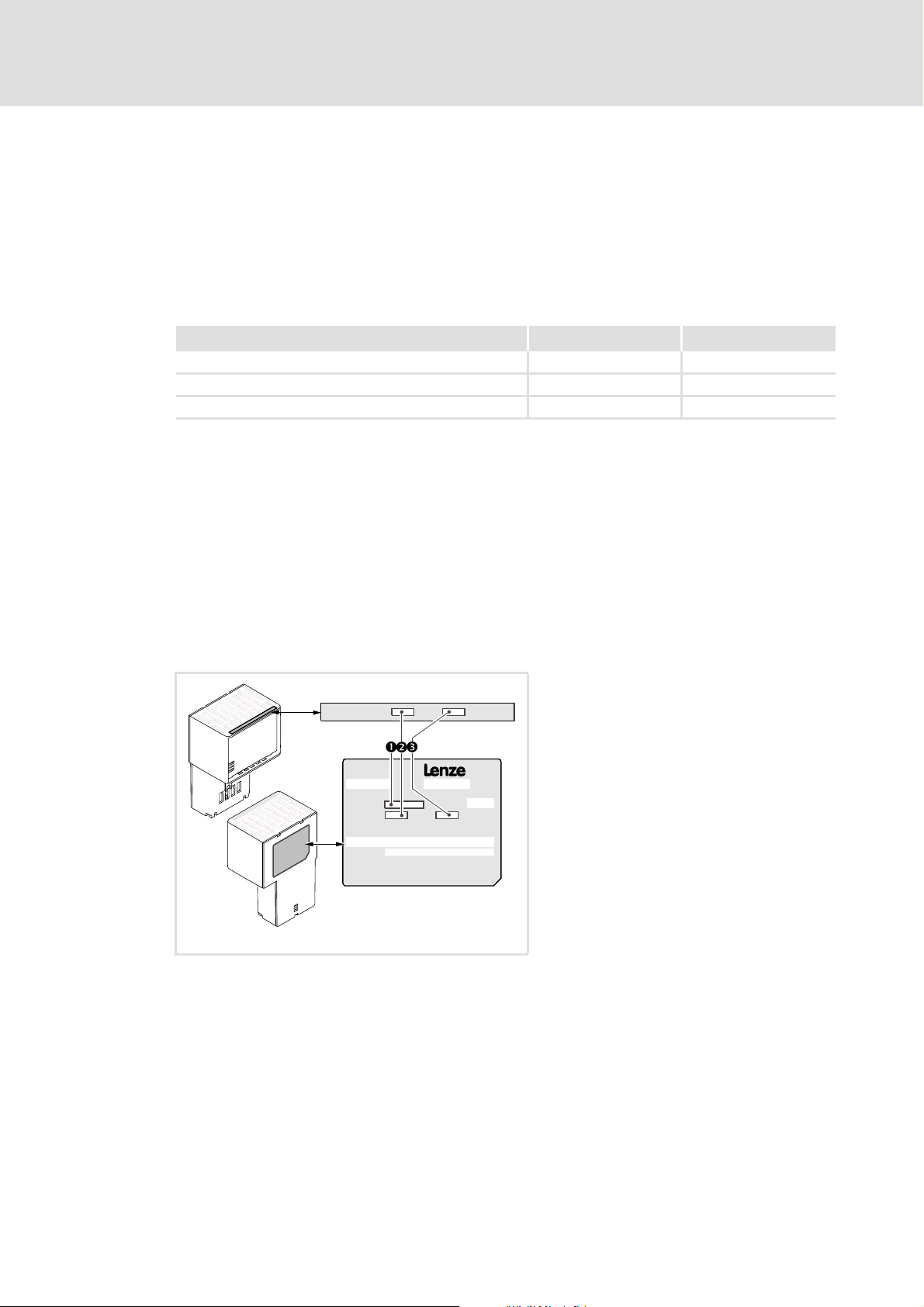
3.2 Identification
The type designation, hardware version, and software version of a communication module
are indicated on its nameplate:
8400
Type:
HW:
Ser.No.:
HW:
SW:
SW:
1 Type designation (type)
E84 Product series
AVersion
Y Module identification: extension module
C Module type: communication module
IB INTERBUS
V/S V: Coated version
S: Standard version
2 Hardware version (HW)
3 Software version (SW)
E84YCPM001E
[3-1] Identification data
14 L EDS84AYCIB EN 4.0 - 11/2010
Page 15

3.3 Product features
Interface module for the INTERBUS communication system for attachment to the
expansion slots of Inverter Drives 8400
The communication module can either be supplied internally by the 8400 standard
device or externally by a separate voltage source.
Slave functionality
Access to all Lenze parameters
DIP switch settings:
– Number of process data words and parameter data words
– Baud rate (500 kbps or 2 Mbps)
Bus coupling via remote bus in accordance with the RS485 standard
Up to 10 process data words are possible
Support of the PMS services:
–Initiate
–Abort
– Reject
–Read
–Write
–Get-OD
–Identify
– Status
E84AYCIB communication manual (INTERBUS)
Product description
Product features
EDS84AYCIB EN 4.0 - 11/2010 L 15
Page 16

E84AYCIB communication manual (INTERBUS)
Product description
Terminals and interfaces
3.4 Terminals and interfaces
2 connections for the INTERBUS
– 1 input (9-pole Sub-D plug)
– 1 output (9-pole Sub-D socket)
2-pole plug connector with spring connection for the external voltage supply of the
communication module
DIP switch for setting the ...
– Number of process data words and parameter data words
–Baud rate
Front LEDs for diagnostics ...
– of the communication module voltage supply;
– of the module status;
– of the INTERBUS status.
[3-2] E84AYCIB communication module (INTERBUS)
E84YCIB001C
S205 DIP switch for setting the ...
• Number of process data words and
parameter data words
•Baud rate
Possible settings through DIP switch
X205 External voltage supply of the communication
module
• 2-pole plug connector with spring
connection
External voltage supply
X206 INTERBUS input (IN)
• 9-pole Sub-D plug
X207 INTERBUS output (OUT)
• 9-pole Sub-D socket
Network topology
INTERBUS connection
MS
5 LED status displays for diagnostics
ME
Module status displays
BS
Fieldbus status displays
BE
DE
( 31)
( 27)
( 28)
( 55)
( 56)
( 34)
16 L EDS84AYCIB EN 4.0 - 11/2010
Page 17

E84AYCIB communication manual (INTERBUS)
4 Technical data
"Inverter Drives 8400" hardware manual
This manual contains data on the ambient conditions and the electromagnetic
compatibility (EMC) that also apply to the communication module.
4.1 General data and operating conditions
Field Values
Order designation • E84AYCIBV (coated version)
• E84AYCIBS: (standard version)
Communication profile INTERBUS
Interfaces • Input (IN): 9-pole Sub-D plug
• Output (OUT): 9-pole Sub-D socket
Communication medium RS485
Network topology Ring
Type of node INTERBUS slave
Number of nodes • 1 master
• 512 slaves
Baud rate 500 kbps or 2 Mbps
(can be set via DIP switch or code)
Max. cable length • 400 m at 500 kbps
• 150 m at 2 Mbps
(between the individual INTERBUS nodes)
Process data words (PD) to be used 0 ... 10: 16 bits/word
(can be set via DIP switch or code)
Parameter data words (PCP) 0, 1, 2, 4: 16 bits/word
(can be set via DIP switch or code)
Max. number of data words 10 (PD + PCP): 16 bits/word
Max. PDU length 64 bytes
INTERBUS identification (module ID) • 3 = 0x3 (PCP 0 words)
• 227 = 0xE3 (PCP 1 word)
• 224 = 0xE0 (PCP 2 words)
• 225 = 0xE1 (PCP 4 words)
Voltage supply External supply via the 2-pole plug connector
• "+": U = 24 V DC (21.6 V - 0 % … 26.4 V + 0 %), I
• "-": Reference potential for external voltage supply
Conformities, approvals CE
Technical data
General data and operating conditions
= 180 mA
max
EDS84AYCIB EN 4.0 - 11/2010 L 17
Page 18

E84AYCIB communication manual (INTERBUS)
Technical data
Protective insulation
4.2 Protective insulation
Danger!
Dangerous electrical voltage
If Inverter Drives 8400 are used on a phase earthed mains with a rated mains
voltage ≥ 400 V, external measures need to be implemented in order to provide
reliable protection against accidental contact.
Possible consequences:
• Death or serious injury
Protective measures:
• If protection against accidental contact needs to be provided for the control
terminals of the controller and for the connections of the plugged-in device
modules, ...
– a double isolating distance must exist.
– the components to be connected must be provided with the second
isolating distance.
Note!
The protective insulation provided in Inverter Drives 8400 is realised in
accordance with EN 61800-5-1.
18 L EDS84AYCIB EN 4.0 - 11/2010
Page 19

E84AYCIB communication manual (INTERBUS)
Technical data
Protective insulation
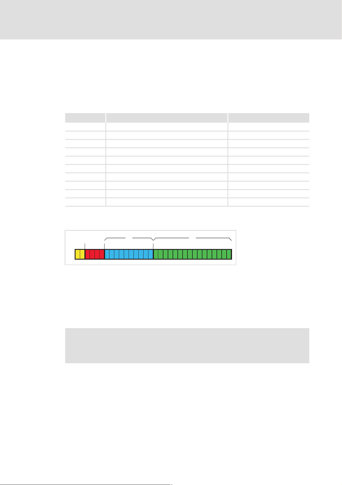
The illustration below ...
shows the arrangement of the terminal strips and the separate potential areas of the
controller.
serves to determine the decisive protective insulation between two terminals located
in differently insulated separate potential areas.
Note!
The INTERBUS input (X206) is isolated from the voltage supply (X205) and the
INTERBUS output (X207).
Bus
X106X106X106X101
X100X100
X105X105
X106X106X106X106
[4-1] Protective insulation in accordance with EN61800-5-1
X206
X207
X3
X3
X4
X4
MCI
X6
X6
Ext. DC
X205
X5
X5
X1X1
Reinforced insulation
Basic insulation
Functional insulation
MMI
E84YCIB007
EDS84AYCIB EN 4.0 - 11/2010 L 19
Page 20

E84AYCIB communication manual (INTERBUS)
Technical data
Protective insulation
Terminal strip Connection
X100 Mains/DC-bus connection
X101 Relay contact
X105 Motor/brake resistor
X106 Motor PTC
X1 System bus (CANopen)
X3 Analog inputs/outputs
X4 Digital outputs
X5 Digital inputs
X6 Diagnostics
MCI Slot for communication module
MMI Slot for memory module
Example
Which type of protective insulation is used between the bus terminal of the device module
in slot MCI and the mains terminal X100?
The separate potential area with the better protective insulation is decisive.
– The separate potential area of the device module bus terminal is "functionally
insulated".
– The separate potential area of the mains terminal has a "reinforced insulation".
Result: The insulation between the mains terminal X100 and the bus terminal is of the
"reinforced insulation" type.
20 L EDS84AYCIB EN 4.0 - 11/2010
Page 21

4.3 Protocol data
Field Values
Process data words 0 ... 10 words (16 bits/word)
Supported PMS services • Initiate
4.4 Communication time
The communication time is the time between the start of a request and the arrival of the
corresponding response.
E84AYCIB communication manual (INTERBUS)
Technical data
Protocol data
•Abort
• Reject
•Read
•Write
•Get-OD
•Identify
• Status
The communication times in the INTERBUS network depend on the...
Processing time in the controller;
Telegram runtime (baud rate / telegram length).
Processing time in the controller
The parameter data and process data are independent of each other.
Data Processing time
Process data Approx. 2ms + 1ms tolerance + runtime of the technology application used
Parameter data Approx. 30 ms + 20 ms tolerance (typical)
• Some codes may require a longer processing time (see software manual/
»Engineer« online help for Inverter Drives 8400).
EDS84AYCIB EN 4.0 - 11/2010 L 21
Page 22
E84AYCIB communication manual (INTERBUS)
Technical data
Dimensions
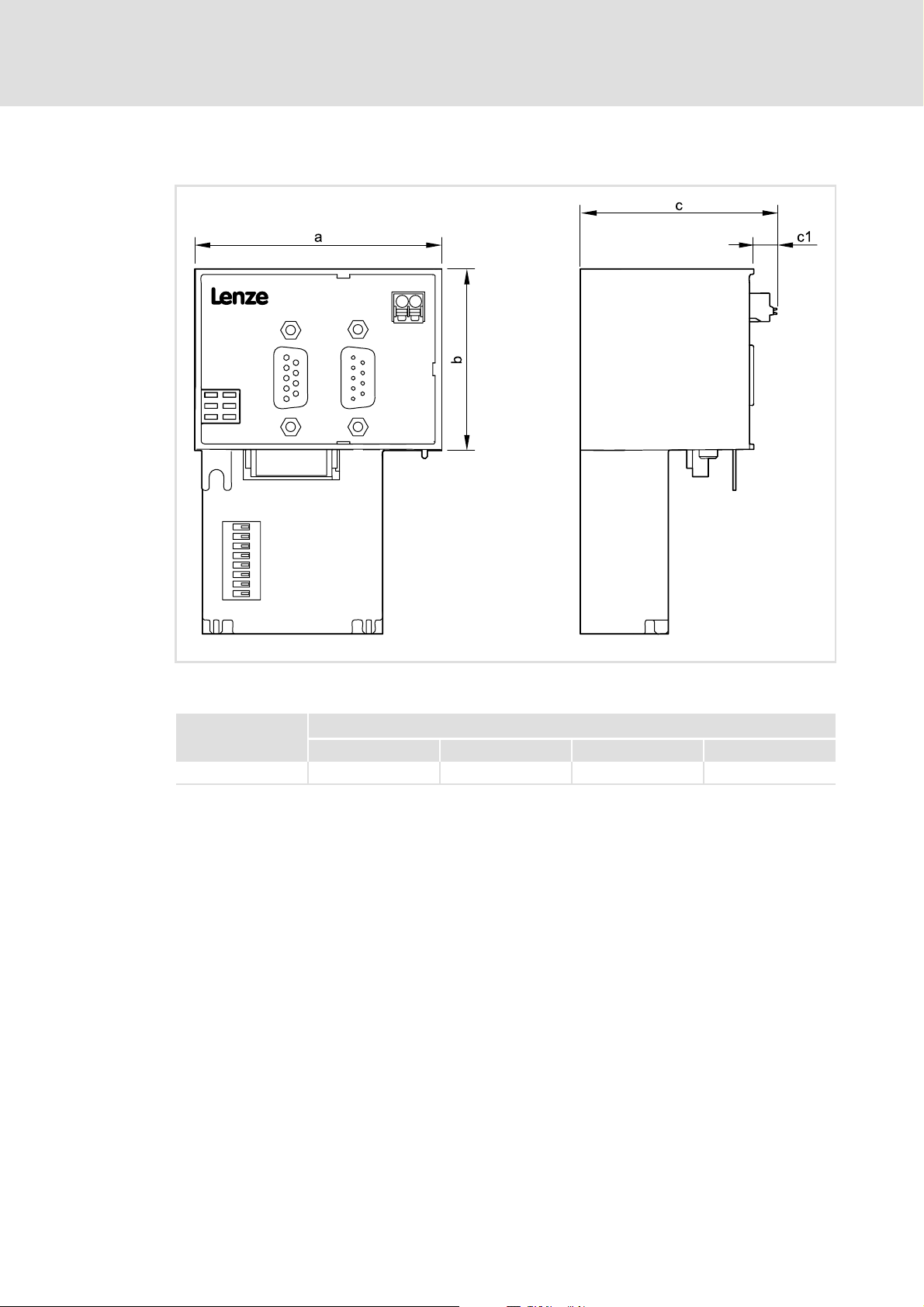
4.5 Dimensions
E84YCIB0016
[4-2] Dimensions
Type Dimensions [mm]
a b c c1
E84AYCIB 67 50 57 8
22 L EDS84AYCIB EN 4.0 - 11/2010
Page 23

5 Installation
Stop!
Electrostatic discharge
Electronic components within the communication module can be damaged or
destroyed by electrostatic discharge.
Possible consequences:
• The communication module is damaged.
• Fieldbus communication is not possible or is faulty.
Protective measures:
• Ensure that you are free of electrostatic charge before you touch the module.
E84AYCIB communication manual (INTERBUS)
Installation
EDS84AYCIB EN 4.0 - 11/2010 L 23
Page 24

E84AYCIB communication manual (INTERBUS)
Installation
Mechanical installation
5.1 Mechanical installation
The communication module can be plugged into the MCI slot or removed from there while
the controller is switched on. When the module is plugged in, it is recognised automatically
and checked for plausibility regarding its function and version.
5.1.1 Mounting for standard devices 0.25 kW and 0.37 kW
E84YCPM002D
[5-1] Mounting for standard devices 0.25 kW and 0.37 kW
Mounting steps
1. Use a screwdriver to lever out the cover of the MCI slot of the standard device and
remove it (1, 2).
2. Loosen the securing screw for the communication module at the standard device (3).
3. Insert the communication module into the MCI slot of the standard device (4).
4. Tighten the securing screw again (5).
24 L EDS84AYCIB EN 4.0 - 11/2010
Page 25

E84AYCIB communication manual (INTERBUS)
5.1.2 Mounting for standard devices from 0.55 kW onwards
[5-2] Mounting for standard devices from 0.55 kW onwards
Installation
Mechanical installation
E84YCPM002A
Mounting steps
1. Slightly impress the pressure surface on the top side of the standard device MCI slot
cover (1).
2. Bend the cover forward and remove it from the standard device (2).
3. Loosen the securing screw for the communication module at the standard device (3).
4. Insert the communication module into the MCI slot of the standard device (4).
5. Tighten the securing screw again (5).
EDS84AYCIB EN 4.0 - 11/2010 L 25
Page 26

E84AYCIB communication manual (INTERBUS)
Installation
Mechanical installation
5.1.3 Replacing the communication module
[5-3] Replacing the communication module
E84YCPM002B
Mounting steps
1. Loosen the securing screw for the communication module at the standard device (1).
2. Remove the communication module from the MCI slot of the standard device (2).
3. Insert the new communication module into the MCI slot of the standard device (3).
4. Tighten the securing screw again (4).
26 L EDS84AYCIB EN 4.0 - 11/2010
Page 27

5.2 Electrical installation
Documentation for the standard device, control system, plant/machine
Observe the notes and wiring instructions contained in this documentation.
5.2.1 EMC-compliant wiring
In typical systems, standard shielding of the Ethernet cables is sufficient.
However, in environments with a very high level of interference, EMC resistance can be
improved by additionally earthing the cable shield on both sides.
For this observe the following notes:
1. Remove the plastic sheath of the cable on a length of 2 cm.
2. Fasten the cable shield onto the shield contact of the standard device.
E84AYCIB communication manual (INTERBUS)
Installation
Electrical installation
5.2.2 Network topology
The bus system must be designed as a ring. Feed and return lines must be integrated in the
same bus cable. The ring goes from the INTERBUS master via all other nodes and back again
to the master.
An INTERBUS ring can consist of maximally 513 nodes (1 master + standard devices
connected).
M
M: Master (master control, e.g. PLC, Industrial PC)
S1 ... Sn: Slaves
S1
Inverter Drive
8400
E84AYCIB
X206
IN
S2
X207
OUT
500 kBit/s: 400 m
2 MBit/s:£150 m£
Sn
Inverter Drive
8400
E84AYCIB
X206
IN IN
X207
OUT
Inverter Drive
8400
E84AYCIB
X206
X207
E94YCIB008
[5-4] INTERBUS ring
EDS84AYCIB EN 4.0 - 11/2010 L 27
Page 28
E84AYCIB communication manual (INTERBUS)
Installation
Electrical installation
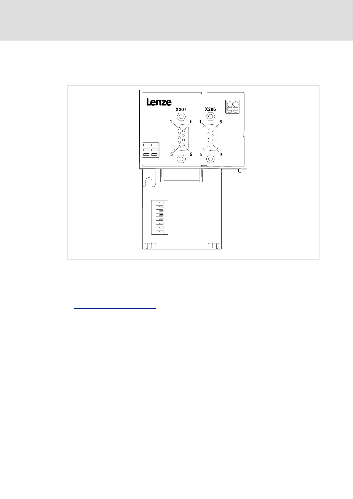
5.2.3 INTERBUS connection
The INTERBUS connection of the communication module is effected via X206 (input, 9-pole
Sub-D plug) and X207 (output, 9-pole Sub-D socket).
[5-5] INTERBUS terminals X206 (input) and X207 (output)
The nodes on the bus system have to be connected to each other by means of a fieldbus
cable in accordance with the INTERBUS specification. INTERBUS cables are for instance
produced by PHOENIX CONTACT (Germany).
Specification of the bus cable
( 30)
E84YCIB001E
28 L EDS84AYCIB EN 4.0 - 11/2010
Page 29

E84AYCIB communication manual (INTERBUS)
Installation
Electrical installation
Assignment of the 9-pole Sub-D plug X206 (IN)
Pin Designation Input/output Description
1DO1 Input RS485: DO1 not inverted
2 DI1 Output RS485: DI1 not inverted
3GND Reference potential
4 Free Not assigned
5Vcc5 Output 5 V DC
6 /DO1 Input RS485: DO1 inverted
7/DI1 Output RS485: DI1 inverted
8Vcc5 Output 5 V DC
9 Free Not assigned
Assignment of the 9-pole Sub-D socket X207 (OUT)
Pin Designation Input/output Description
1 DO2 Output RS485: DO2 not inverted
2 DI2 Input RS485: DI2 not inverted
3GND Reference potential
4GND
5Vcc5 Output 5 V DC
6/DO2 Output RS485: DO2 inverted
7 /DI2 Input RS485: DI2 inverted
8Vcc5 Output 5 V DC
9 RBST Signalling input Connection to the outgoing INTERBUS is plugged.
EDS84AYCIB EN 4.0 - 11/2010 L 29
Page 30

E84AYCIB communication manual (INTERBUS)
Installation
Electrical installation
5.2.4 Specification of the bus cable
Note!
Only use cables that meet the listed specifications.
Specification of the INTERBUS cable
Cable type Sold by the meter
(e.g. PHOENIX CONTACT: IBS RBC meter-T, order no. 28 06 28 6)
No. of conductors 3 x 2, twisted in pairs, with joint shielding
Conductor cross-section > 0.2 mm
DC-cable resistance < 96 Ω/km
Impedance (characteristic) • 120 Ω ± 20 % (f = 64 kHz)
• 100 Ω ± 15 Ω (f > 1 MHz)
Capacitance per unit length < 60 nF/km (f = 800 Hz)
2
5.2.5 Bus cable length
Adapt the baud rate according to the bus cable length:
Baud rate Cable length between the individual INTERBUS nodes
500 kbps Max. 400 m
2 Mbps Max. 150 m
Note!
Select the baud rate which depends on the data volume, cycle time, and number
of nodes only as high as required for the application.
30 L EDS84AYCIB EN 4.0 - 11/2010
Page 31
5.2.6 External voltage supply
The communication module can be supplied externally with voltage via separate supply
cables at the 2-pole plug connector (X205).
Note!
With external voltage supply, always use a separate power supply unit, safely
separated in accordance with EN 61800-5-1 in every control cabinet ("SELV" /
"PELV").
External voltage supply of the communication module is necessary if the bus
communication is to continue when the supply of the standard device fails.
It is not possible to access the parameters of a standard device that is disconnected
from the mains.
E84AYCIB communication manual (INTERBUS)
Installation
Electrical installation
Wiring the X205 plug connector
Stop!
Only wire the plug connector if the standard device is disconnected from the
mains.
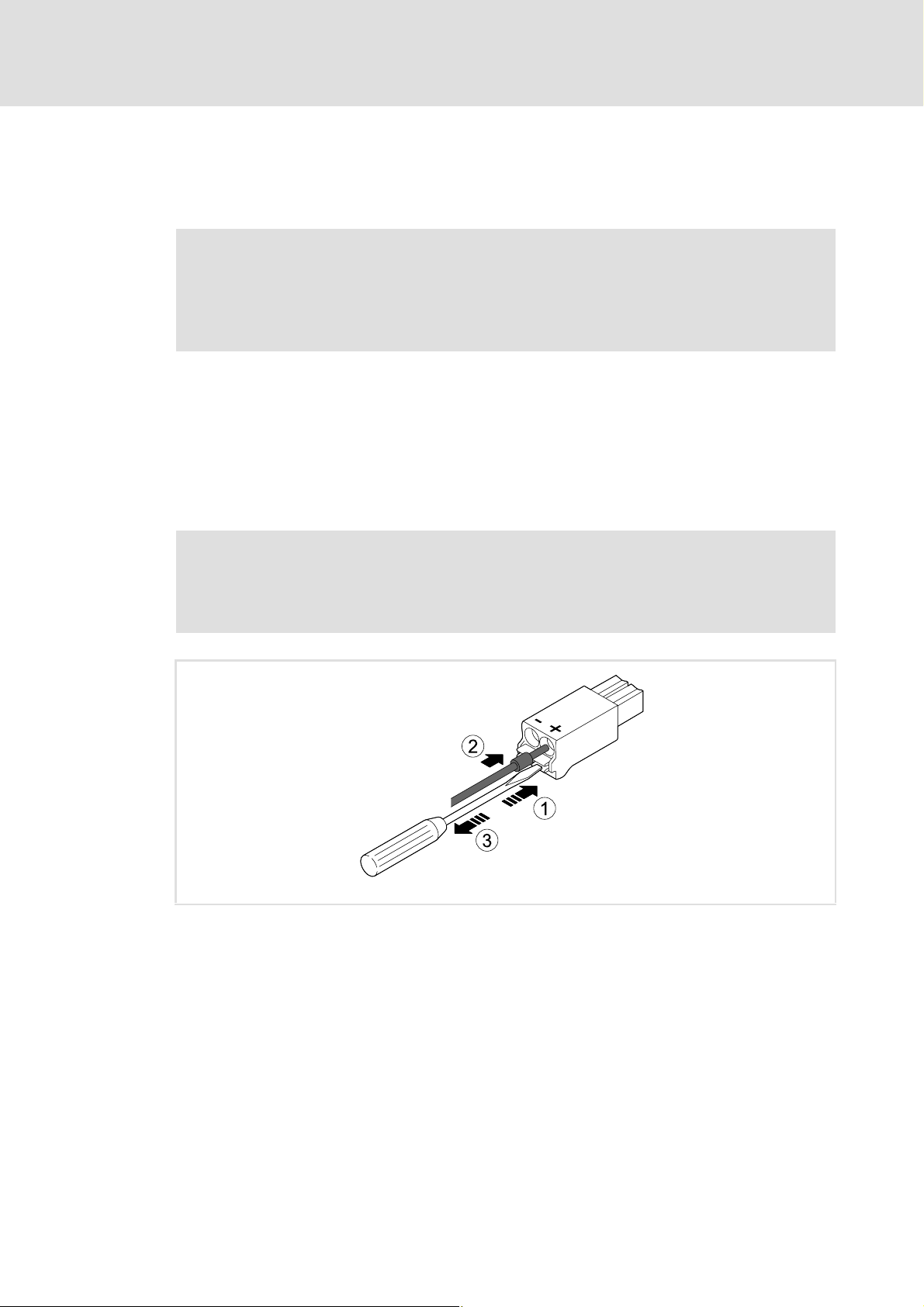
[5-6] Wiring of the 2-pole plug connector with spring connection
E84AYCXX010
How to wire the plug connector with spring connection:
1. Place a screwdriver into the notch below the terminal and keep it pressed.
2. Place the supply cable in the terminal.
3. Remove the screwdriver from the notch.
EDS84AYCIB EN 4.0 - 11/2010 L 31
Page 32
E84AYCIB communication manual (INTERBUS)
Installation
Electrical installation
Assignment of the X205 plug connector
Designation Explanation
+ U = 24 V DC (21.6 V - 0 % … 26.4 V + 0 %)
I = 180 mA
- Reference potential for external voltage supply
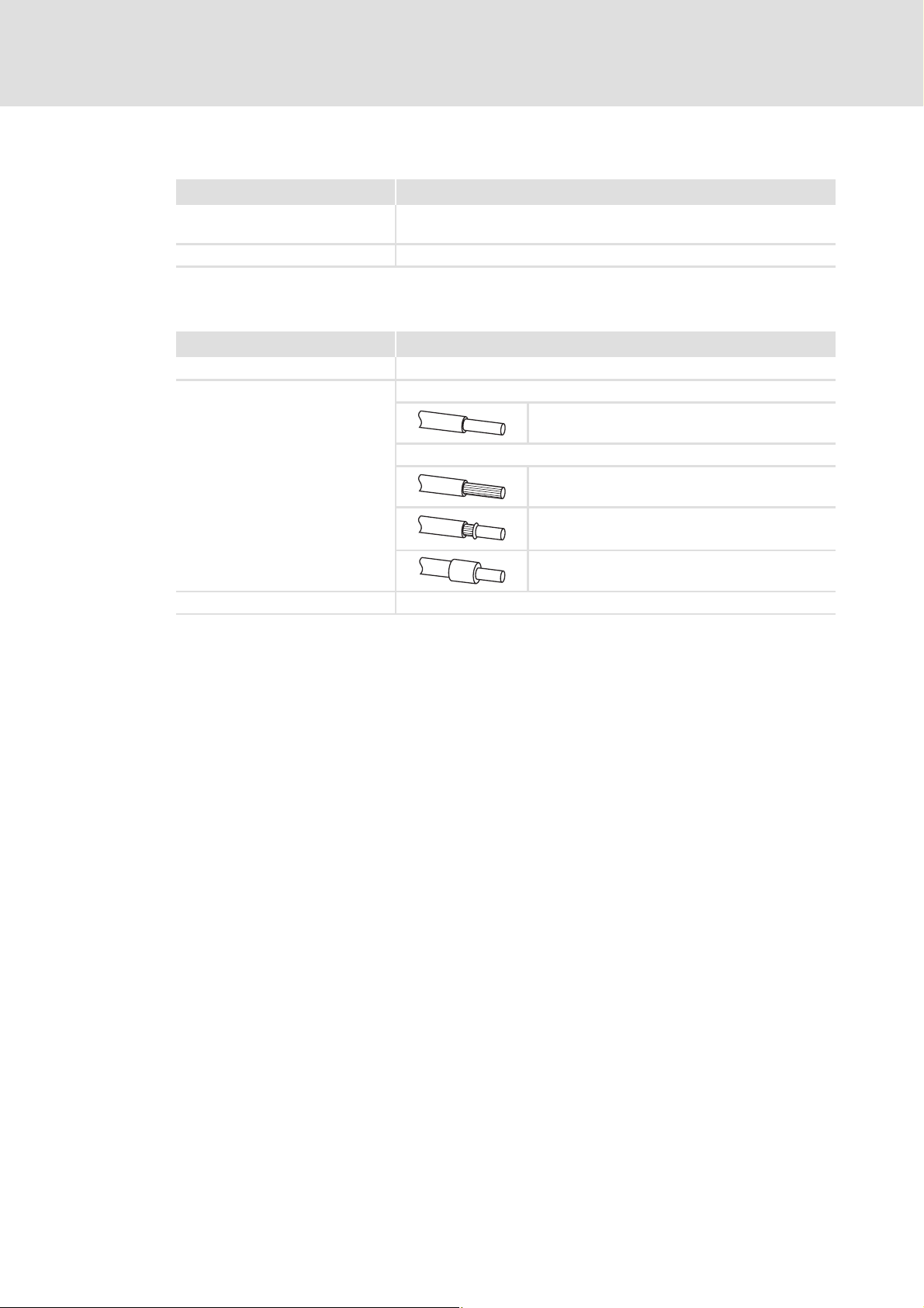
Terminal data
Field Values
Electrical connection 2-pole plug connector with spring connection
Possible connections Rigid:
Flexible:
0.2 ... 1.5 mm
Without wire end ferrule
0.2 ... 1.5 mm
With wire end ferrule, without plastic sleeve
0.2 ... 1.5 mm
2
(AWG 24 ... 16)
2
(AWG 24 ... 16)
2
(AWG 24 ... 16)
Stripping length 10 mm
With wire end ferrule, with plastic sleeve
0.2 ... 1.5 mm
2
(AWG 24 ... 16)
32 L EDS84AYCIB EN 4.0 - 11/2010
Page 33

6 Commissioning
During commissioning, system-specific data such as motor parameters, operating
parameters, responses, and parameters for fieldbus communication are defined for the
controller. For Lenze devices this is effected via the so-called codes.
The codes of the controller and for communication are saved non-volatilely as a data set in
the memory module.
Additionally there are codes for diagnostics and monitoring of the nodes.
E84AYCIB communication manual (INTERBUS)
Commissioning
Before initial switch-on
Parameters of the communication module
6.1 Before initial switch-on
Stop!
Before switching on the standard device with the communication module for
the first time, check the entire wiring for completeness, short circuit, and earth
fault.
( 63)
EDS84AYCIB EN 4.0 - 11/2010 L 33
Page 34

E84AYCIB communication manual (INTERBUS)
Commissioning
Possible settings through DIP switch
6.2 Possible settings through DIP switch
The following can be set through the DIP switch
(S205):
Number of process data words (PD)
Switches: 1 ... 4
Number of parameter data words (PCP)
Switches: 5 and 6
Baud rate
Switch: 8
Lenze setting: All switches "OFF"
Switch 7 has no function.
( 35)
( 36)
( 37)
[6-1] DIP switch
Note!
E84YCIB001D
To make any modified settings take effect, switch the voltage supply of the
communication module off and then on again.
Initial switch-on
The settings can also be made via codes:
• All DIP switches = "OFF" (Lenze setting):
At switch-on, the configuration from codes C13892
becomes active.
• At least one DIP switch = "ON":
At switch-on, the values are accepted from the switch positions.
The data word sum (PD + PCP) may maximally amount to 10 words.
( 39)
, C13893, and C13894
34 L EDS84AYCIB EN 4.0 - 11/2010
Page 35

E84AYCIB communication manual (INTERBUS)
6.2.1 Setting the number of process data words (PD)
Commissioning
Possible settings through DIP switch
The number of process data words (PD) can be set via switches 1 ... 4 or code C13893
(for this, see Settings in the »Engineer«
( 38)).
0 ... 10 process data words can be used.
The current setting is displayed in C13860/2
.
Note!
The data word sum (PD + PCP) must amount to 1 ... 10 words. Impermissible
settings are reported by the LED "BE" (red blinking).
LED status displays
The communication module then continues to operate internally with the
following values:
•PD = 2 (words)
•PCP = 1 (word)
DIP switch Number of
OFF
ON
12345678
( 54)
PD
0 OFF OFF OFF OFF 4
1 OFF OFF OFF ON
2OFFOFFON OFF
3OFFOFFON ON
4OFFON OFF OFF
5OFFON OFF ON
6OFFON ON OFF
7OFFON ON ON 2
8 ON OFF OFF OFF
9 ON OFF OFF ON 1
10 ON OFF ON OFF 0
1 2 3 4
Switch Max. number
of PCP
EDS84AYCIB EN 4.0 - 11/2010 L 35
Page 36

E84AYCIB communication manual (INTERBUS)
Commissioning
Possible settings through DIP switch
6.2.2 Setting the number of parameter data words (PCP)
The number of parameter data words (PCP) can be set via switches 5 and 6 or code
C13892
0, 1, 2 or 4 parameter data words can be used.
(for this, see Settings in the »Engineer« ( 38)).
The current setting is displayed in C13860/1
.
Note!
The data word sum (PD + PCP) must amount to 1 ... 10 words. Impermissible
settings are reported by the LED "BE" (red blinking).
LED status displays
The communication module then continues to operate internally with the
following values:
•PD = 2 (words)
•PCP = 1 (word)
DIP switch Number of PCP Switch Max. number of
OFF
12345678
ON
( 54)
5 6
0OFFOFF100x03
1OFFON 90xE3
PD
ID code
[hex]
2 ON OFF 8 0xE0
4 ON ON 60xE1
36 L EDS84AYCIB EN 4.0 - 11/2010
Page 37

6.2.3 Setting the baud rate
E84AYCIB communication manual (INTERBUS)
Commissioning
Possible settings through DIP switch
The baud rate can be set via switch 8 or code C13894
»Engineer« ( 38)).
The current setting of the baud rate is displayed in C13863/
DIP switch Switch 8 Baud rate Max. cable length between adjacent nodes
OFF
12345678
ON
OFF 500 kbps 400 m
ON 2 Mbps 150 m
(for this, see Settings in the
.
EDS84AYCIB EN 4.0 - 11/2010 L 37
Page 38

E84AYCIB communication manual (INTERBUS)
Commissioning
Settings in the »Engineer«
6.3 Settings in the »Engineer«
Under the Settings tab in the »Engineer« you can set the following parameters:
Number of parameter data words (PCP, C13892
Number of process data words (PD, C13893
Baud rate (C13894
)
)
)
38 L EDS84AYCIB EN 4.0 - 11/2010
Page 39

6.4 Initial switch-on
Documentation for the standard device
Observe the safety instructions and information on residual hazards contained
in this documentation.
Note!
Establishing communication
In order to establish communication via an externally supplied communication
module, the standard device must be switched on as well.
After communication has been established, the power on/off state of the
standard device is irrelevant.
E84AYCIB communication manual (INTERBUS)
Commissioning
Initial switch-on
Activating altered settings
To activate altered settings, ...
• use standard device code C00002 to execute the device command "11: save
all parameter sets", and ...
• then switch the voltage supply of the communication module off and on
again.
Protection against uncontrolled restart
Following a fault (e.g. short-term mains failure), it is sometimes undesirable or
even impermissible for the drive to restart.
In the Lenze setting for Inverter Drives 8400, restart protection is active.
The restart behaviour of the controller can be set using C00142 ("autostart
option"):
• C00142 = 9 (Lenze setting)
– The controller remains inhibited (even when the fault is no longer active).
– Bit 0 (inhibit at power-on) and bit 3 (inhibit in the case of undervoltage) are
set.
– An explicit controller enable causes the drive to start up in a controlled
manner: LOW-HIGH edge at digital input X4/RFR.
• C00142 = 8 (enabled)
– In order to directly enable the device at switch-on, bit 0 must be set to zero
(FALSE).
– An uncontrolled restart of the drive is possible.
EDS84AYCIB EN 4.0 - 11/2010 L 39
Page 40

E84AYCIB communication manual (INTERBUS)
Data transfer
7 Data transfer
The INTERBUS master and controller communicate with each other by exchanging data
telegrams via INTERBUS. The user data area of the data telegram contains parameter data
or process data. In the controller, the parameter data and process data are assigned to
different communication channels.
Communication channels
The process data channel transmits process data.
– The process data are used to actuate the controller.
– The host (master) can directly access the process data. In the PLC, for instance, the
data are directly assigned to the I/O area.
– Process data are not saved in the controller.
– Process data are transmitted cyclically between the host and the controllers
(permanent exchange of current input and output data).
– Process data for instance are setpoints, actual values, control words, and status
words.
– In the case of Inverter Drives 8400 a maximum of 16 process data words (16 bits/
word) can be exchanged for each direction.
Note!
Observe the direction of the flow of information!
• Process input data (Rx data):
– Process data from the controller (slave) to the master
• Process output data (Tx data):
– Process data from the master to the controller (slave)
The parameter data channel transmits parameter data.
– The parameter data channel provides access to all Lenze codes.
– The transmission of parameter data usually is not time-critical.
– Parameter data for instance are operating parameters, motor data, and diagnostics
information.
– The parameter changes must be stored via code C00002 of the Inverter Drive 8400.
– The parameter data channel assigns up to 4 words of the input and output data
words in the master and is structured identically for both transmission directions.
40 L EDS84AYCIB EN 4.0 - 11/2010
Page 41

E84AYCIB communication manual (INTERBUS)
/3B0FL,Q
"
/3B0FL2XW
"
8 Process data transfer
8.1 Access to process data / PDO mapping
The process data (MCI-PDOs) are transferred via the MCI interface.
A maximum of 16 words is exchanged for each direction.
The process data are accessed via the port blocks LP_MciIn and LP_MciOut. These port
blocks are also referred to as process data channels.
The port block LP_MciIn maps the MCI-PDOs received.
The port block LP_MciOut maps the MCI-PDOs to be transmitted.
The port/function block interconnection of the process data objects (PDO) is made via
the Lenze »Engineer«.
Process data transfer
Access to process data / PDO mapping
)LHOGEXV
&RPPXQLFDWLRQPRGXOH
0&,LQWHUIDFH
E&WUOB%
E&WUOB%
Z&WUO
E,QB%
E,QB%
Z,Q
Z,Q
GQ,QBS
[8-1] External and internal data transfer between the bus system, controller, and application
$SSOLFDWLRQ
)%LQWHUFRQQHFWLRQ
E6WDWHB%
E6WDWHB%
Z6WDWH
E2XWB%
E2XWB%
Z2XW
Z2XW
GQ2XWBS
Software manual / »Engineer« online help for the Inverter Drive 8400
Here you'll find detailed information on the port /function block interconnection
in the »Engineer« and on port blocks.
EDS84AYCIB EN 4.0 - 11/2010 L 41
Page 42

E84AYCIB communication manual (INTERBUS)
Process data transfer
Preconfigured port interconnection of the process data objects (PDO)
Note!
The »Engineer« screenshots shown in the following are only examples for the
setting sequence and the resulting displays.
The data in the display fields highlighted in white may differ from the ones of
your project.
8.2 Preconfigured port interconnection of the process data objects (PDO)
The preconfigured port interconnection of the process data objects can be activated by
setting standard device code C00007 = "40: MCI".
The »FB Editor« serves to display the port blocks "LP_MciIn" and "LP_MciOut" with the
preconfigured interconnections:
42 L EDS84AYCIB EN 4.0 - 11/2010
Page 43

E84AYCIB communication manual (INTERBUS)
Process data transfer
Freely configurating the port interconnection of the process data objects (PDO)
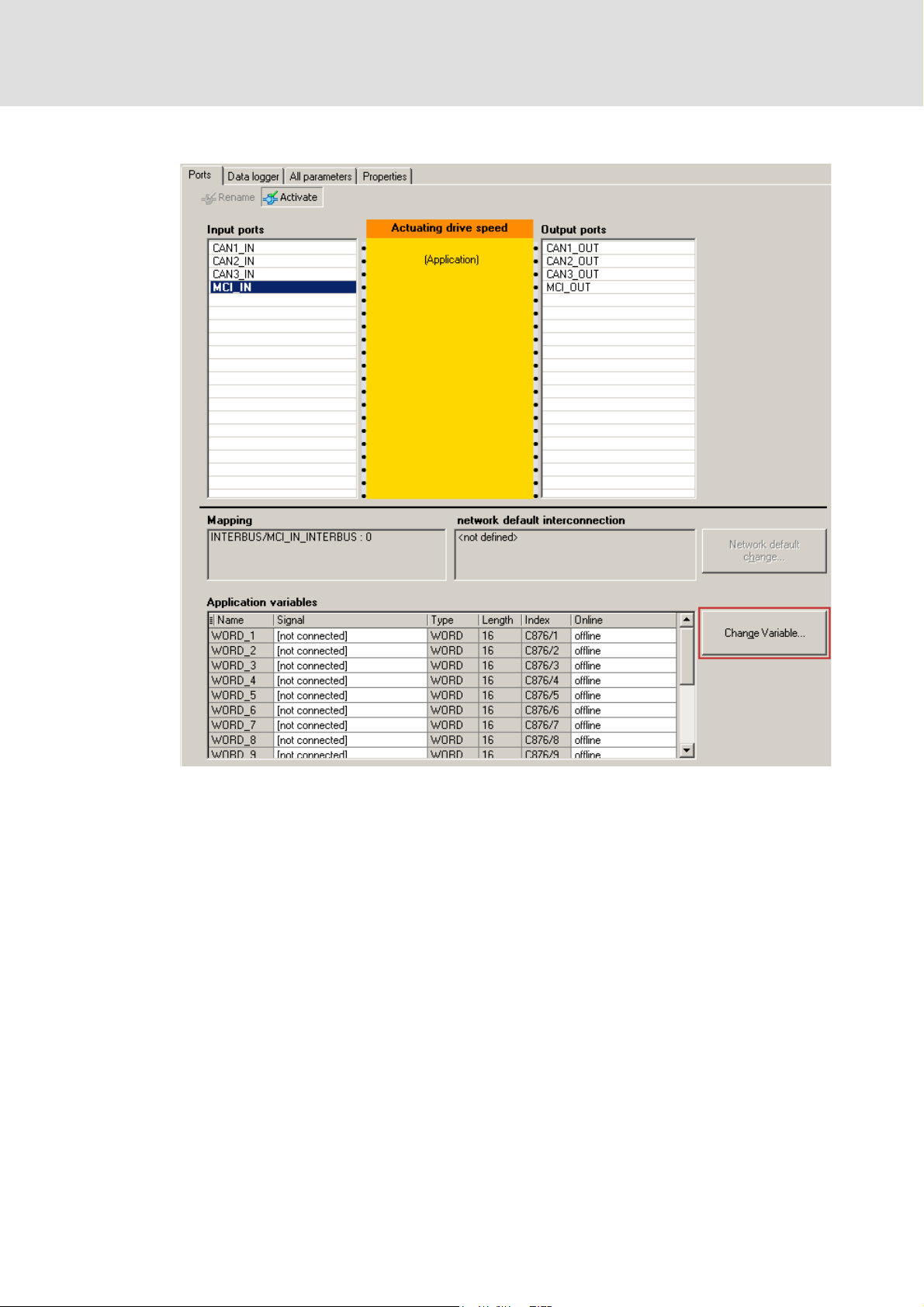
8.3 Freely configurating the port interconnection of the process data objects (PDO)
How to freely configurate the port interconnection in the »Engineer«:
1. Go to the Process data objects tab to click the Go to application button.
2. Select the "MCI_IN" or "MCI_OUT" port blocks in the Ports tab via mouse-click and
activate them with the Activate button.
EDS84AYCIB EN 4.0 - 11/2010 L 43
Page 44
E84AYCIB communication manual (INTERBUS)
Process data transfer
Freely configurating the port interconnection of the process data objects (PDO)
3. Click the Change variable... button.
44 L EDS84AYCIB EN 4.0 - 11/2010
Page 45

E84AYCIB communication manual (INTERBUS)
Process data transfer
Freely configurating the port interconnection of the process data objects (PDO)
4. The button serves to assign signals to the process data words in the
Assignment signal --> function block dialog box.
Select signals and then click the OK button.
EDS84AYCIB EN 4.0 - 11/2010 L 45
Page 46

E84AYCIB communication manual (INTERBUS)
Process data transfer
Freely configurating the port interconnection of the process data objects (PDO)
Moreover you can assign signals to the individual control and status bits at the
WORD_1... WORD_4 process data words via the and buttons.
Select the signals and then click OK.
46 L EDS84AYCIB EN 4.0 - 11/2010
Page 47

E84AYCIB communication manual (INTERBUS)
Process data transfer
Freely configurating the port interconnection of the process data objects (PDO)
Tip!
When the port blocks "LP_MciIn" and "LP_MciOut" are activated (see 1.), they will
be visible in the »FB Editor«. Here you can also assign signals to the process data
words.
EDS84AYCIB EN 4.0 - 11/2010 L 47
Page 48

E84AYCIB communication manual (INTERBUS)
Parameter data transfer
Addressing of the parameter data
9 Parameter data transfer
9.1 Addressing of the parameter data
The parameter data are addressed via codes which are listed in the form of a code table in
this communication manual and in the corresponding documentation for your controller.
Parameter reference
( 63)
Addressing of the Lenze parameters
With the INTERBUS parameter data channel, the parameters of a device are not directly
addressed via the Lenze codes but via an index and subindex.
The conversion is made via an offset (24575 or 0x5FFF):
INTERBUS index (dec) = 24575 - Lenze code number (dec)
INTERBUS index (hex) = 0x5FFF - Lenze code number (hex)
Example of C00105 (deceleration time quick stop (QSP))
INTERBUS index (dec) = 24575 - 105 = 24470
INTERBUS index (hex) = 0x5FFF - 0x69 = 0x5F96
9.2 Initialising PCP communication
Make entries into the CRL (communication relation list) so that communication between
the INTERBUS master and the communication module can take place.
Make the following entries in the CRL of the INTERBUS master:
Field name Entry
Communication reference 2
Connection type Master slave acyclic
Connection attribute Defined
Max-PDU Sending-High-Prio 0
Max-PDU Sending-Low-Prio 64
Max-PDU Receiving-High-Prio 0
Max-PDU Receiving-Low-Prio 64
Supported Services Request 0x803000
Supported Services Response 0x000000
Maximum SCC 1
Maximum RCC 1
Maximum SAC 1
Maximum RAC 1
48 L EDS84AYCIB EN 4.0 - 11/2010
Page 49

9.3 Supported PMS services
Parameters are transferred via the PCP channel (PCP = Peripherals Communication
Protocol). This is executed via PMS services.
In the following, only parameters and their contents are given that are returned by the
Lenze controllers. All other transfer parameters of the given PMS services can be obtained
from the corresponding descriptions of the INTERBUS master.
The following PMS services are supported by Lenze controllers:
Initiate: Establish a connection from the INTERBUS master to the controller
Abort: Abort connection
Reject: Reject impermissible PMS service
Read: Read parameters
Write: Write parameters
Get-OD: Read out the object directory
E84AYCIB communication manual (INTERBUS)
Parameter data transfer
Supported PMS services
Identify: Identification of the controller
Status: Read the status of the controller
9.3.1 Initiate
The "Initiate" PMS service establishes a logic connection between the INTERBUS master
and the communication module.
The controller provides the following parameters:
Designation Value Description
Profile number 0 No profile is supported.
Password 0 The password function of INTERBUS is not supported.
Access groups 0 There are no access groups.
Access-Protection Supported TRUE Access protection is supported.
Version OD 0 Version of the object directory
9.3.2 Abort
The "Abort" PMS service aborts a logic connection between the INTERBUS master and the
communication module.
9.3.3 Reject
The "Reject" PMS service rejects a non-supported PMS service.
EDS84AYCIB EN 4.0 - 11/2010 L 49
Page 50

E84AYCIB communication manual (INTERBUS)
Parameter data transfer
Supported PMS services
9.3.4 Read / Write
The "Read" PMS service reads parameters from the controller. The controller outputs the
requested parameter or an error message.
The "Write" PMS service writes to parameters of the controller. The controller outputs a
positive feedback or an error message.
The following error messages can occur:
Error Class Error Code Additional
Code
[hex]
6 3 0x00 No access authorisation
6 5 0x10 Impermissible job parameter
650x11Invalid subindex
6 5 0x12 Data length too big
6 5 0x13 Data length too small
6 6 0x00 Object is not a parameter
6 7 0x00 Object does not exist
6 8 0x00 Data types do not comply with each other
8 0 0x00 Job cannot be executed
8 0 0x20 Job currently cannot be executed
8 0 0x21 Cannot be executed because of local control
8 0 0x22 Cannot be executed because of device state
8 0 0x30 Quit value range / parameter can only be changed when the
8 0 0x31 Value of the parameter is too high
8 0 0x32 Value of the parameter is too low
8 0 0x33 Subparameter outside the value range
8 0 0x34 Value of the subparameter is too high
8 0 0x35 Value of the subparameter is too low
8 0 0x36 Maximum value is lower than minimum value
8 0 0x41 Communication object cannot be displayed on process data
8 0 0x42 Length of the process data exceeded
8 0 0x43 General collision with other values
Description
controller is inhibited.
9.3.5 Get-OD
The "Get-OD" PMS service reads out the object description for every parameter and data
type.
50 L EDS84AYCIB EN 4.0 - 11/2010
Page 51
9.3.6 Identify
The "Identify" PMS service provides information on how to identify the controller.
The controller with the plugged-on communication module provides the following
parameters for this:
Parameter Type Description
Device manufacturer Visible string Company name "Lenze"
Device type Visible-string (15 characters) Device name for the controller and the
Device version Visible-string (15 characters) Firmware version of the controller and the
Example: Visible string "device type" (15 characters)
1 2 3 4 5 6 7 8 9 10 11 12 13 14 15
E 8 4 A F G H C A F Y I B
E84AYCIB communication manual (INTERBUS)
Parameter data transfer
Supported PMS services
communication module
communication module
Character Description
1 ... 3 Product range of the controller and the communication module (E84 = 8400 series)
4Blank
5 ... 6 A: Version of the controller
F: Firmware of the controller
7 ... 9 G: Device / controller
SC: StateLine C
HC: HighLine C
10 Blank
11 ... 12 A: Version of the communication module
F: Firmware of the communication module
13 ... 15 Y: Communication module
IB: INTERBUS
Structure of the visible string "device version" (15 characters)
1 2 3 4 5 6 7 8 9 10 11 12 13 14 15
0 4 . 0 0 0 1 . 0 0
Character Description
1 ... 5 Firmware version of the controller (from C00099/0, e.g. "04.00.xx.yy", without internal revision
6Blank
7 ... 11 Firmware version of the communication module (from C13902
12 ... 15 Blank
status ["xx"] and build status ["yy"])
, e.g. "01.00.xx.yy", without internal
revision status ["xx"] and build status ["yy"])
EDS84AYCIB EN 4.0 - 11/2010 L 51
Page 52

E84AYCIB communication manual (INTERBUS)
Parameter data transfer
Supported PMS services
9.3.7 Status
The "Status" PMS service provides status information about the controller.
The controller provides the following values:
Status Value Description
Logical status 0 = ready for communication Information about the current operating
Physical status • 0 = ready for operation (device state
"OPERATION ENABLED")
• 1 = ready for operation to a limited extent
(all other device states)
Local Detail 0 Is not supported.
mode of the controller with regard to
communication
Information about the current operating
status of the
controller.
52 L EDS84AYCIB EN 4.0 - 11/2010
Page 53

10 Monitoring
Communication fault
If INTERBUS communication is interrupted, e.g. due to cable break or INTERBUS master
failure, no process data are transmitted to the slave in the
"IBS-ACTIVE
E84AYCIB communication manual (INTERBUS)
Monitoring
" ( 57) status.
After the time to be parameterised by the user in C13881
parameterised in C13880/1
Settings in the »Engineer«
Under the Settings tab in the »Engineer« you can set the following parameters:
Reaction on interrupted INTERBUS communication (C13880/1
Delete process data (C13885
– Setting of the process data which the controller is to process further for maintaining
internal communication when the INTERBUS has failed.
is executed in the controller.
)
has elapsed, the response
)
Monitoring time for INTERBUS communication failure (C13881)
EDS84AYCIB EN 4.0 - 11/2010 L 53
Page 54

E84AYCIB communication manual (INTERBUS)
Diagnostics
LED status displays
11 Diagnostics
For fault diagnostics, the INTERBUS module is provided with the LEDs on the front.
Furthermore code C13861
Diagnostics with the »Engineer«
11.1 LED status displays
can be used to query the current bus status (for this, see
( 57)).
Note!
In normal operation only the LEDs MS ( 55) and BS ( 56) should be lit constantly.
The following status displays are distinguished:
Module status displays
Fieldbus status displays
( 55)
( 56)
54 L EDS84AYCIB EN 4.0 - 11/2010
Page 55

11.1.1 Module status displays
The LEDs MS, ME and DE display the module status.
MS
E84AYCIB communication manual (INTERBUS)
Diagnostics
LED status displays
ME
DE
LED Colour Status Description
MS Green On
The communication module is supplied with voltage and has
established a connection to the standard device.
Blinking
200 ms
200 ms
The communication module is supplied with voltage, but has not
established a connection to the standard device. (Standard device is
switched off, initialising or not present.)
ME Red Blinking
200 ms
200 ms
An error in the communication module has occurred.
DE Red On
The communication module is not accepted by the standard device
(see notes in the documentation for the standard device), or the
standard device is not active.
E84YCIB006
EDS84AYCIB EN 4.0 - 11/2010 L 55
Page 56

E84AYCIB communication manual (INTERBUS)
Diagnostics
LED status displays
11.1.2 Fieldbus status displays
The LEDs BS and BE display the fieldbus status.
BS
BE
E84YCIB006
LED Colour Status Description
BS Green Off The communication module is not active on the fieldbus.
Data cycles are not executed.
Blinking
200 ms
200 ms
Communication has been established via the communication
module. The INTERBUS is active. Data cycles are executed.
BE Red On
INTERBUS communication is interrupted.
Data cycles are not executed.
Blinking
200 ms
200 ms
Impermissible setting:
• Data word sum (PD + PCP) > 10
• Data word sum (PD + PCP) = 0
The communication module has been initialised and continues to
operate internally with the following values:
• PD = 2 (words)
• PCP = 1 (word)
56 L EDS84AYCIB EN 4.0 - 11/2010
Page 57

11.2 Querying the current bus status
E84AYCIB communication manual (INTERBUS)
Diagnostics
Querying the current bus status
Code C13861
Value of C13861
[hex]
0xyyy0 IBS-INIT Initialisation
0xyyy1 IBS-ACTIVE The bus is active. Data cycles are executed.
0xyyy2 IBS-READY The bus is ready for operation. No data cycles are executed.
yyy = device-internal use
displays the current bus status of the INTERBUS node:
Bus status Description
Diagnostics with the »Engineer«
In the »Engineer« the Diagnostics tab serves to display various pieces of diagnostic
INTERBUS information.
EDS84AYCIB EN 4.0 - 11/2010 L 57
Page 58
E84AYCIB communication manual (INTERBUS)
Diagnostics
Diagnostic data
11.3 Diagnostic data
Pending diagnostic data are signalised by the master via an alarm message to the slave.
Errors and warnings in the standard device and the plugged-in module are transmitted
to the master as extended diagnostic messages.
The diagnostic data can be viewed via the hexadecimal representation of the
Engineering tool.
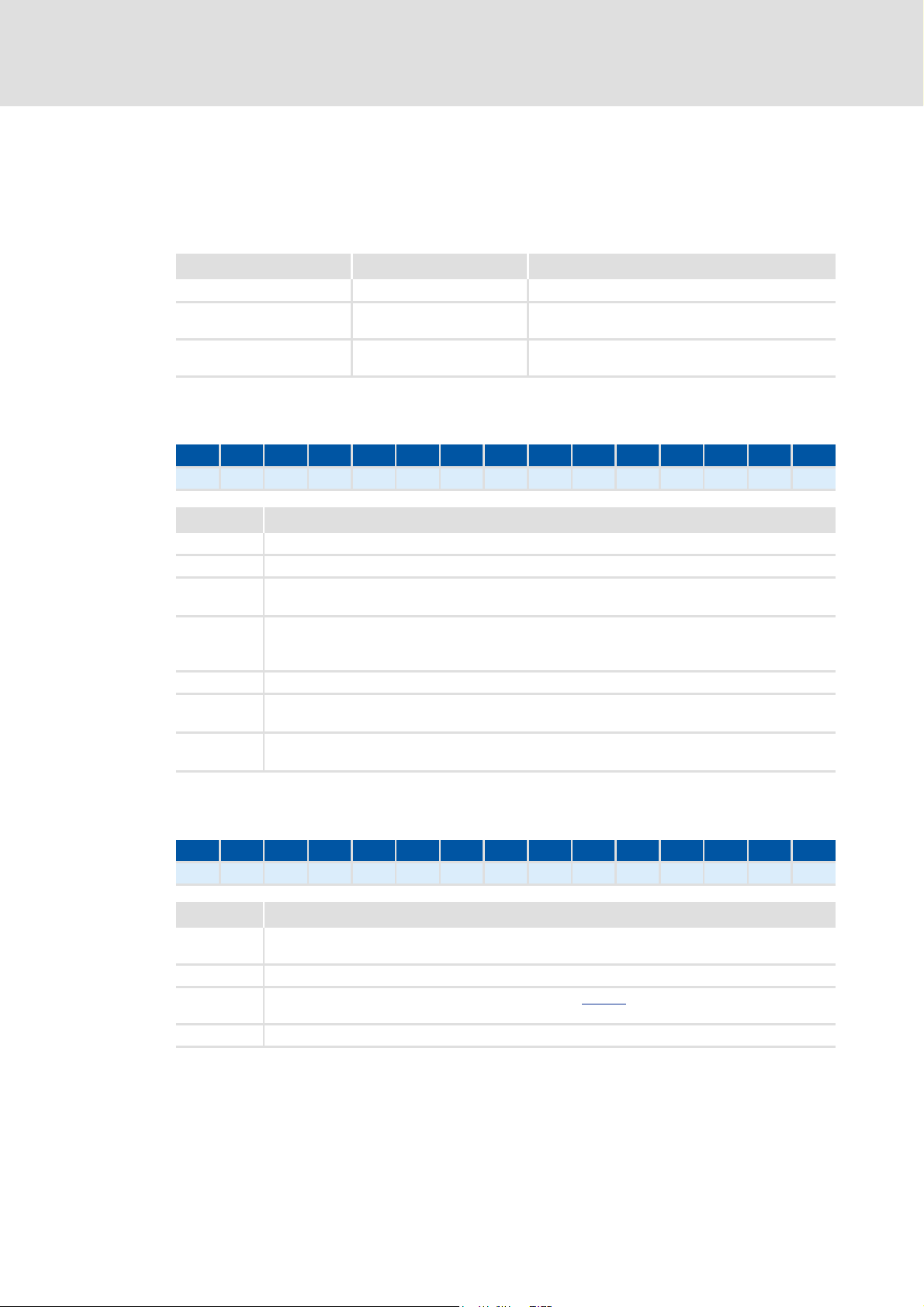
Bytes Meaning Value [hex]
1 ... 6 Diagnostics block header 0x0010 001C 0100
7 ... 8 Alarm type 0x0001 (Diagnosis)
9 ... 12 API 0x0000 0000
13, 14 Slot number 0x0001 / 0x0002
15, 16 Subslot number 0x0001
17 ... 20 Module ID number ID according to module
21 ... 24 Submodule number ID according to module
25, 26 Alarm specifier 0xB000
27, 28 User structure identifier 0x0001
29 ... 32 Error code of the Inverter Drive 8400
Error code of the Inverter Drive 8400
210 3
30
31
Bit
29
[11-1] Structure of the error number
Bytes 29 ... 32 of the diagnostic message contain the error code of the Inverter Drive
8400.
The logbook and standard device code C00165 show the error number in the following
syntax to improve the legibility:
[error type].[error subject area no.].[error ID]
Software manual/»Engineer« online help for the Inverter Drive 8400
Here you'll find detailed information on the structure and the contents of the
error codes.
A Reserved
162526
B Error type
015
C Error subject area
D Error ID
58 L EDS84AYCIB EN 4.0 - 11/2010
Page 59

E84AYCIB communication manual (INTERBUS)
Short overview (A-Z) of the INTERBUS error messages
12 Error messages
This chapter provides the error messages of the communication module as a supplement
to the error list in the software manual and the »Engineer« online help for the Inverter
Drive 8400.
Software manual/»Engineer« online help for the Inverter Drive 8400
Here you'll find general information on diagnostics & fault analysis and error
messages.
12.1 Short overview (A-Z) of the INTERBUS error messages
The following table contains all error messages of the communication module in
alphabetical order with the preset error response and, if available, the parameter for
setting the error response.
Error messages
Tip!
When you click the cross-reference in the last column, you will get to the detailed
description (causes and remedies) of the corresponding error message.
Error text Error type Subject area
Communication stack reset Error 444 33062 - 0x01bc8126
Data exchange stopped No response 444 33073 C13880/1 0x01bc8131
Internal error Error 444 24592 - 0x01bc6010
Internal error Error 444 24593 - 0x01bc6011
Internal error Error 444 24832 - 0x01bc6100
Internal error Error 444 24833 - 0x01bc6101
Invalid configuration Warning 444 33061 - 0x01bc8125
Invalid initialisation Warning 444 33063 - 0x01bc8127
Invalid module configuration Error 444 25648 - 0x01bc6430
Invalid parameter set Error 444 25631 - 0x01bc641f
Lenze setting loaded Error 444 25632 - 0x01bc6420
Lost connection to 8400 base device Error 444 12544 - 0x01bc3100
Memory not accessible Error 444 21809 - 0x01bc5531
Memory read error Error 444 21810 - 0x01bc5532
Memory write error Error 444 21811 - 0x01bc5533
no.
Error no. Adjustable inDetailed
information
EDS84AYCIB EN 4.0 - 11/2010 L 59
Page 60

E84AYCIB communication manual (INTERBUS)
Error messages
Possible causes and remedies
12.2 Possible causes and remedies
This chapter includes a list of all error messages of the communication module in
numerically ascending order of the error number. Possible causes and remedies as well as
responses to error messages are described in detail.
Tip!
A list of all error messages of the communication module in alphabetical order is
provided in the previous chapter "Short overview (A-Z) of the INTERBUS error
messages" ( 59).
Lost connection to 8400 base device [0x01bc3100]
Response (Lenze setting in bold) Setting: not possible
None System fault : Fault Trouble Quick stop by trouble Warning locked Warning Information
Cause Remedy
Network cable (plug) is defective.
Network cable at INTERBUS terminal X206 (IN) or X207
(OUT) is disconnected.
Memory not accessible [0x01bc5531]
Memory read error [0x01bc5532]
Memory write error [0x01bc5533]
Response (Lenze setting in bold) Setting: not possible
None System fault : Fault Trouble Quick stop by trouble Warning locked Warning Information
Cause Remedy
Memory could not be accessed. Send module with error description to Lenze.
Response (Lenze setting in bold) Setting: not possible
None System fault : Fault Trouble Quick stop by trouble Warning locked Warning Information
Cause Remedy
Parameter in the memory module could not be read. Repeat download of the application (including module).
Response (Lenze setting in bold) Setting: not possible
None System fault : Fault Trouble Quick stop by trouble Warning locked Warning Information
Check network cable (plug) and replace it, if required.
Plug in network cable at INTERBUS terminal X206 (IN) or
X207 (OUT).
Cause Remedy
Parameter in the memory module could not be written. Repeat download of the application (including module).
60 L EDS84AYCIB EN 4.0 - 11/2010
Page 61

Internal error [0x01bc6010]
Response (Lenze setting in bold) Setting: not possible
None System fault : Fault Trouble Quick stop by trouble Warning locked Warning Information
Cause Remedy
Communication module is defective. Send communication module with error description to
Internal error [0x01bc6011]
Response (Lenze setting in bold) Setting: not possible
None System fault : Fault Trouble Quick stop by trouble Warning locked Warning Information
Cause Remedy
Communication module is defective. Send communication module with error description to
Internal error [0x01bc6100]
E84AYCIB communication manual (INTERBUS)
Error messages
Possible causes and remedies
Lenze.
Lenze.
Response (Lenze setting in bold) Setting: not possible
None System fault : Fault Trouble Quick stop by trouble Warning locked Warning Information
Cause Remedy
Communication module is defective. Send communication module with error description to
Internal error [0x01bc6101]
Response (Lenze setting in bold) Setting: not possible
None System fault : Fault Trouble Quick stop by trouble Warning locked Warning Information
Cause Remedy
Communication module is defective. Send communication module with error description to
Invalid parameter set [0x01bc641f]
Response (Lenze setting in bold) Setting: not possible
None System fault : Fault Trouble Quick stop by trouble Warning locked Warning Information
Cause Remedy
Loading of an active parameter set was not possible. Repeat download of the application (including module).
Lenze setting loaded [0x01bc6420]
Lenze.
Lenze.
Response (Lenze setting in bold) Setting: not possible
None System fault : Fault Trouble Quick stop by trouble Warning locked Warning Information
Cause Remedy
Access via standard device to the parameter set in the
memory module failed.
EDS84AYCIB EN 4.0 - 11/2010 L 61
Repeat download of the application (including module).
Page 62

E84AYCIB communication manual (INTERBUS)
Error messages
Possible causes and remedies
Invalid module configuration [0x01bc6430]
Response (Lenze setting in bold) Setting: not possible
None System fault : Fault Trouble Quick stop by trouble Warning locked Warning Information
Cause Remedy
Module configuration is faulty. Check and correct module configuration.
Invalid configuration [0x01bc8125]
Response (Lenze setting in bold) Setting: not possible
None System fault Fault Trouble Quick stop by trouble Warning locked : Warning Information
Cause Remedy
The active configuration is invalid:
• Data word sum (PD + PCP) > 10 words
• Data word sum (PD + PCP) = 0
Communication stack reset [0x01bc8126]
Adapt the number of PD and PCP:
• Data word sum (PD + PCP) = 1 ... 10 words
Response (Lenze setting in bold) Setting: not possible
None System fault : Fault Trouble Quick stop by trouble Warning locked Warning Information
Cause Remedy
Error during processing the INTERBUS services Execute reinitialisation by the master.
Invalid initialisation [0x01bc8127]
Data exchange stopped [0x01bc8131]
Response (Lenze setting in bold) Setting: not possible
None System fault Fault Trouble Quick stop by trouble Warning locked : Warning Information
Cause Remedy
The INTERBUS initialisation has failed. Execute reinitialisation by the master.
Response (Lenze setting in bold) Setting: C13880/1
: None System fault : Fault Trouble : Quick stop by trouble : Warning locked Warning : Information
Cause Remedy
The data exchange at the INTERBUS has been
terminated.
• Check cables and connections.
• Execute reinitialisation by the master.
62 L EDS84AYCIB EN 4.0 - 11/2010
Page 63

E84AYCIB communication manual (INTERBUS)
13 Parameter reference
This chapter supplements the parameter list and the table of attributes in the software
manual and the »Engineer« online help for the Inverter Drive 8400 by parameters of the
E84AYCIB communication module (INTERBUS).
Software manual/»Engineer« online help for the Inverter Drive 8400
Here you'll find general information about parameters.
13.1 Parameters of the communication module
This chapter lists the parameters of the E84AYCIB communication module (INTERBUS) in
numerically ascending order.
Parameter reference
Parameters of the communication module
C13850
C13851
Parameter | Name:
C13850 | All words to master
Display of the process data words which are transmitted from the communication module to the master.
• Subcodes 1 ... 16 display all process data words to the master. Only those which are configured are valid.
Maximally the first 10 words are relevant to the E84AYCIB INTERBUS module.
Display area (min. value | unit | max. value)
0 65535
Subcodes Information
C13850/1
...
C13850/16
; Read access Write access CINH PLC-STOP No transfer PDO_MAP_RX PDO_MAP_TX COM MOT
Parameter | Name:
C13851 | All words from master
Display of the process data words which are transmitted from the master to the communication module.
• Subcodes 1 ... 16 display all process data words from the master. Only those which are configured are valid.
Maximally the first 10 words are relevant to the E84AYCIB INTERBUS module.
Display area (min. value | unit | max. value)
0 65535
Subcodes Information
C13851/1
...
C13851/16
; Read access Write access CINH PLC-STOP No transfer PDO_MAP_RX PDO_MAP_TX COM MOT
Data type: UNSIGNED_16
Index: 10725
Data type: UNSIGNED_16
Index: 10724
= 29E5
d
= 29E4
d
h
h
EDS84AYCIB EN 4.0 - 11/2010 L 63
Page 64

E84AYCIB communication manual (INTERBUS)
Parameter reference
Parameters of the communication module
C13852
C13853
Parameter | Name:
C13852 | All words to standard device
Data type: UNSIGNED_16
Index: 10723
= 29E3
d
Display of the process data words which are transmitted from the communication module to the standard device.
• Subcodes 1 ... 16 display all process data words to the standard device. Maximally the first 10 words are relevant
to the E84AYCIB INTERBUS module.
Display area (min. value | unit | max. value)
0 65535
Subcodes Information
C13852/1
...
C13852/16
; Read access Write access CINH PLC-STOP No transfer PDO_MAP_RX PDO_MAP_TX COM MOT
Parameter | Name:
C13853 | All words from standard device
Data type: UNSIGNED_16
Index: 10722
= 29E2
d
Display of the process data words which are transmitted from the standard device to the communication module.
• Subcodes 1 ... 16 display all process data words from the standard device. Maximally the first 10 words are
relevant to the E84AYCIB INTERBUS module.
Display area (min. value | unit | max. value)
0 65535
Subcodes Information
C13853/1
...
C13853/16
; Read access Write access CINH PLC-STOP No transfer PDO_MAP_RX PDO_MAP_TX COM MOT
h
h
C13860
Parameter | Name:
Data type: UNSIGNED_8
C13860 | Active settings
Display of the set number for
• Parameter data words (PCP)
• Process data words (PD) to be used
(16 bits/word)
Display area (min. value | unit | max. value)
0 255
Subcodes Information
C13860/1 Display of PCP data length
C13860/2 Display of process data length
; Read access Write access CINH PLC-STOP No transfer PDO_MAP_RX PDO_MAP_TX COM MOT
Index: 10715
= 29DB
d
h
64 L EDS84AYCIB EN 4.0 - 11/2010
Page 65

C13861
E84AYCIB communication manual (INTERBUS)
Parameter reference
Parameters of the communication module
C13862
Parameter | Name:
C13861 | Bus status
Display of the current bus status
Querying the current bus status
( 57)
Meaning of the resulting hexadecimal values:
• 0xyyy0 = IBS-INIT
• 0xyyy1 = IBS-ACTIVE
• 0xyyy2 = IBS-READY
Value is bit coded: Information
Bit 0 Bit 0
... ...
Bit 15 Bit 15
; Read access Write access CINH PLC-STOP No transfer PDO_MAP_RX PDO_MAP_TX COM MOT
Parameter | Name:
Data type: UNSIGNED_16
C13862 | Counter
Counter for cycles and INTERBUS resets
Display area (min. value | unit | max. value)
0 65535
Subcodes Information
C13862/1 Data cycles per second
C13862/2 Total data cycles
C13862/3 Number of INTERBUS resets
C13862/4 Number of ID cycles
; Read access Write access CINH PLC-STOP No transfer PDO_MAP_RX PDO_MAP_TX COM MOT
Data type: BITFIELD_16
Index: 10714
Index: 10713
= 29DA
d
= 29D9
d
h
h
C13863
Parameter | Name:
Data type: UNSIGNED_8
C13863 | Active baud rate
Display of the set baud rate
Selection list (read only)
0 500 kbps
1 2.00 Mbps
; Read access Write access CINH PLC-STOP No transfer PDO_MAP_RX PDO_MAP_TX COM MOT
Index: 10712
= 29D8
d
h
EDS84AYCIB EN 4.0 - 11/2010 L 65
Page 66

E84AYCIB communication manual (INTERBUS)
Parameter reference
Parameters of the communication module
C13880
C13881
Parameter | Name:
C13880 | Reaction on communication failure
Data type: UNSIGNED_8
Index: 10695
= 29C7
d
Monitoring response in case of a communication fault
A change in the monitoring response becomes effective immediately.
Communication fault
( 53)
Selection list
0 No response
1 Error
3 Quick stop by trouble
4 Warning locked
6 Information
Subcodes Lenze setting Information
C13880/1 0: No response Response to interrupted INTERBUS communication
; Read access ; Write access CINH PLC-STOP No transfer PDO_MAP_RX PDO_MAP_TX COM MOT
Parameter | Name:
C13881 | Monitoring time for Interbus communication failure
Data type: UNSIGNED_16
Index: 10694
= 29C6
d
If the "IBS-ACTIVE" status (INTERBUS is active and data are cyclically exchanged) is quit, the response parameterised
in C13880/1
is executed after the monitoring time set for the data exchange has elapsed.
• The value "65535" in this code deactivates monitoring.
• A change in monitoring is effective immediately.
Communication fault
( 53)
Setting range (min. value | unit | max. value) Lenze setting
0 ms 65535 65535 ms
; Read access ; Write access CINH PLC-STOP No transfer PDO_MAP_RX PDO_MAP_TX COM MOT
h
h
C13885
Parameter | Name:
C13885 | Delete process data
Data type: UNSIGNED_8
Index: 10690
= 29C2
d
Setting of the process data which the controller is to process further for maintaining internal communication when
the INTERBUS has failed.
Selection list (Lenze setting printed in bold)
0 Use of the last master process data
1 Process data are set to the value '0'
; Read access ; Write access CINH PLC-STOP No transfer PDO_MAP_RX PDO_MAP_TX COM MOT
h
66 L EDS84AYCIB EN 4.0 - 11/2010
Page 67

C13892
E84AYCIB communication manual (INTERBUS)
Parameter reference
Parameters of the communication module
C13893
Parameter | Name:
C13892 | PCP - length
Data type: UNSIGNED_8
Index: 10683
Setting of the number of the parameter data words to be used (PCP)
The setting is activated ...
• if all DIP switches (S205) are in the "OFF" position;
• after executing the "11: Save start parameters" device command via standard device code C00002 and
performing another mains switching of the communication module/drive afterwards.
Setting the number of parameter data words (PCP)
( 36)
Selection list (Lenze setting printed in bold)
0No PCB data
11 word
22 words
44 words
; Read access ; Write access CINH PLC-STOP No transfer PDO_MAP_RX PDO_MAP_TX COM MOT
Parameter | Name:
C13893 | Process data length
Data type: UNSIGNED_8
Index: 10682
Setting of the number of the process data words to be used (PD)
The setting is activated ...
• if all DIP switches (S205) are in the "OFF" position;
• after executing the "11: Save start parameters" device command via standard device code C00002 and
performing another mains switching of the communication module/drive afterwards.
Setting the number of process data words (PD)
( 35)
Selection list (Lenze setting printed in bold)
0No process data
11 word
22 words
33 words
44 words
55 words
66 words
77 words
88 words
99 words
10 10 words
; Read access ; Write access CINH PLC-STOP No transfer PDO_MAP_RX PDO_MAP_TX COM MOT
= 29BB
d
= 29BA
d
h
h
EDS84AYCIB EN 4.0 - 11/2010 L 67
Page 68

E84AYCIB communication manual (INTERBUS)
Parameter reference
Parameters of the communication module
C13894
C13900
C13901
Parameter | Name:
C13894 | Baud rate
Data type: UNSIGNED_8
Index: 10681
Setting of the baud rate
The setting is activated ...
• if all DIP switches (S205) are in the "OFF" position;
• after executing the "11: Save start parameters" device command via standard device code C00002 and
performing another mains switching of the communication module/drive afterwards.
Setting the baud rate
( 37)
Selection list (Lenze setting printed in bold)
0 500 kbps
1 2.00 Mbps
; Read access ; Write access CINH PLC-STOP No transfer PDO_MAP_RX PDO_MAP_TX COM MOT
Parameter | Name:
C13900 | Firmware product type
Data type: VISIBLE_STRING
Index: 10675
Display of the product type (string with a length of 8 bytes)
The following identification code is output: "E94AFYIB".
; Read access Write access CINH PLC-STOP No transfer PDO_MAP_RX PDO_MAP_TX COM MOT
Parameter | Name:
C13901 | Firmware compilation date
Data type: VISIBLE_STRING
Index: 10674
Display of the compilation date of the firmware (string with a length of 20 bytes)
The date ("MMM TT JJJJ") and time ("hh:mm:ss") are output, e.g. "Mar 21 2005 12:31:21".
; Read access Write access CINH PLC-STOP No transfer PDO_MAP_RX PDO_MAP_TX COM MOT
= 29B9
d
= 29B3
d
= 29B2
d
h
h
h
C13902
Parameter | Name:
Data type: VISIBLE_STRING
C13902 | Firmware version
Display of the firmware version (string with a length of 11 bytes)
The identification code is output, e.g. "01.00.00.00".
; Read access Write access CINH PLC-STOP No transfer PDO_MAP_RX PDO_MAP_TX COM MOT
Index: 10673
= 29B1
d
h
68 L EDS84AYCIB EN 4.0 - 11/2010
Page 69

C13920
E84AYCIB communication manual (INTERBUS)
Parameter reference
Parameters of the communication module
Parameter | Name:
C13920 | Display DIP switch setting
Display of the current DIP switch position
• The set PCP data length is displayed in C13860/1
• The set process data length is displayed in C13860/2
• The set baud rate is displayed in C13863
Possible settings through DIP switch
Value is bit coded: Information
Bit 0 DIP 8 Baud rate
Bit 1 DIP 7 No function
Bit 2 DIP 6 Number of parameter data words (PCP)
Bit 3 DIP 5
Bit 4 DIP 4 Number of process data words (PD)
Bit 5 DIP 3
Bit 6 DIP 2
Bit 7 DIP 1
; Read access Write access CINH PLC-STOP No transfer PDO_MAP_RX PDO_MAP_TX COM MOT
.
( 34)
.
.
Data type: BITFIELD_8
Index: 10655
= 299F
d
h
EDS84AYCIB EN 4.0 - 11/2010 L 69
Page 70

E84AYCIB communication manual (INTERBUS)
Parameter reference
Table of attributes
13.2 Table of attributes
The table of attributes contains information required for communicating with the
controller via parameters.
How to read the table of attributes:
Column Meaning Entry
Code Parameter name Cxxxxx
Name Parameter short text (display text) Text
Index dec Index by which the parameter is addressed.
hex 5FFF
Data DS Data structure E Single variable
DA Number of array elements (subcodes) Number
DT Data type BITFIELD_8 1 byte, bit-coded
The subindex for array variables corresponds to the
Lenze subcode number.
Factor Factor for data transmission via a bus system,
Access R Read access ; Reading permitted
W Write access ; Writing permitted
CINH Controller inhibit required ; Writing is only possible when the controller is inhibited
depending on the number of decimal positions
24575 - Lenze code number Is only required for access via a bus
- Lenze code number
h
A Array variable
BITFIELD_16 2 bytes, bit-coded
BITFIELD_32 4 bytes, bit-coded
INTEGER_8 1 byte with sign
INTEGER_16 2 bytes, with sign
INTEGER_32 4 bytes with sign
UNSIGNED_8 1 byte without sign
UNSIGNED_16 2 bytes, without sign
UNSIGNED_32 4 bytes, without sign
VISIBLE_STRING ASCII string
OCTET_STRING
Factor 1 ≡ no decimal positions
system.
(one parameter element only)
(multiple parameter elements)
10 ≡ 1 decimal position
100 ≡ 2 decimal positions
1000 ≡ 3 decimal positions
70 L EDS84AYCIB EN 4.0 - 11/2010
Page 71

E84AYCIB communication manual (INTERBUS)
Parameter reference
Table of attributes
Table of attributes
Code Name Index Data Access
dec hex DS DA DT Factor R W CINH
C13850
C13851
C13852
C13853
C13860
C13861
C13862
C13863
C13880
C13881
C13885
C13892
C13893
C13894
C13900
C13901
C13902
C13920
All words to master 10725 29E5 A 16 UNSIGNED_16 1 ;
All words from master 10724 29E4 A 16 UNSIGNED_16 1 ;
All words to standard device 10723 29E3 A 16 UNSIGNED_16 1 ;
All words from standard device 10722 29E2 A 16 UNSIGNED_16 1 ;
Active settings 10715 29DB A 2 UNSIGNED_8 1 ;
Bus status 10714 29DA E 1 BITFIELD_16 ;
Counter 10713 29D9 A 4 UNSIGNED_16 1 ;
Active baud rate 10712 29D8 E 1 UNSIGNED_8 1 ;
Reaction on communication failure 10695 29C7 A 1 UNSIGNED_8 1 ;;
Monitoring time for Interbus
communication failure
Delete process data 10690 29C2 E 1 UNSIGNED_8 1 ;;
PCP - length 10683 29BB E 1 UNSIGNED_8 1 ;;
Process data length 10682 29BA E 1 UNSIGNED_8 1 ;;
Baud rate 10681 29B9 E 1 UNSIGNED_8 1 ;;
Firmware product type 10675 29B3 E 1 VISIBLE_STRING ;
Firmware compilation date 10674 29B2 E 1 VISIBLE_STRING ;
Firmware version 10673 29B1 E 1 VISIBLE_STRING ;
Display DIP switch setting 10655 299F E 1 BITFIELD_8 ;
10694 29C6 E 1 UNSIGNED_16 1 ;;
EDS84AYCIB EN 4.0 - 11/2010 L 71
Page 72

E84AYCIB communication manual (INTERBUS)
Index
14 Index
Zahlen
9-pole Sub-D plug 29
9-pole Sub-D socket 29
A
Abort (PMS service) 49
Access to process data 41
Activating altered settings 39
Active baud rate (C13863) 65
Active settings (C13860) 64
Addressing of the Lenze parameters 48
Addressing of the parameter data 48
All words from master (C13851) 63
All words from standard device (C13853) 64
All words to master (C13850) 63
All words to standard device (C13852) 64
Application as directed 14
Application notes (representation) 11
Approvals 17
Assignment of the 9-pole Sub-D plug 29
Assignment of the 9-pole Sub-D socket 29
B
Baud rate 17
Baud rate (C13894) 68
Before initial switch-on 33
Bus cable length 30
Bus status (C13861) 65
C
C13850 | All words to master 63
C13851 | All words from master 63
C13852 | All words to standard device 64
C13853 | All words from standard device 64
C13860 | Active settings 64
C13861 | Bus status 65
C13862 | Counter 65
C13863 | Active baud rate 65
C13880 | Reaction on communication failure 66
C13881 | Monitoring time for Interbus communication
failure
66
C13885 | Delete process data 66
C13892 | PCP - length 67
C13893 | Process data length 67
C13894 | Baud rate 68
C13900 | Firmware product type 68
C13901 | Firmware compilation date 68
C13902 | Firmware version 68
C13920 | Display DIP switch setting 69
Cable length 17
Carrying out the port interconnection in the
»Engineer«
Codes 63
Commissioning 33
Communication channels 40
Communication fault 53
Communication medium 17
Communication profile 17
Communication stack reset (error message) 62
Communication time 21
Conformities 17
Conventions 9
Conventions used 9
Copyright 2
Counter (C13862) 65
CRL (communication relation list) 48
43
D
Data exchange stopped (error message) 62
Data transfer 40
Delete process data (C13885) 66
Device- and application-specific safety instructions 13
Device protection 13
Diagnostic data 58
Diagnostic messages 58
Diagnostics 54
Diagnostics with the »Engineer« 57
Dimensions 22
DIP switch settings 34
Display DIP switch setting (C13920) 69
Document history 8
E
Electrical installation 27
EMC-compliant wiring 27
Error code of the Inverter Drive 8400 58
Error messages 59
Causes and remedies 60
Error messages (PCP services Read / Write) 50
Error messages (short overview) 59
Error number
0x01bc3100
0x01bc5531 60
0x01bc5532 60
0x01bc5533 60
0x01bc6010 61
0x01bc6011 61
0x01bc6100 61
0x01bc6101 61
0x01bc641f 61
0x01bc6420 61
0x01bc6430 62
0x01bc8125 62
60
72 L EDS84AYCIB EN 4.0 - 11/2010
Page 73

E84AYCIB communication manual (INTERBUS)
Index
0x01bc8126 62
0x01bc8127 62
0x01bc8131 62
Establishing communication 39
EtherCAT error messages
Causes and remedies
External voltage supply 31
60
F
Fieldbus status displays 56
Firmware compilation date (C13901) 68
Firmware product type (C13900) 68
Firmware version (C13902) 68
G
General data 17
General safety instructions and application notes 12
Get-OD (PMS service) 50
I
IBS-ACTIVE 57
IBS-INIT 57
IBS-READY 57
Identification 14
Identify (PMS service) 51
Initial switch-on 39
Initialising PCP communication 48
Initiate (PMS service) 49
Installation 23
INTERBUS connection 28
INTERBUS identification 17
INTERBUS ring 27
Interfaces 16, 17
Internal error (error message) 61
Invalid configuration (error message) 62
Invalid initialisation (error message) 62
Invalid module configuration (error message) 62
Invalid parameter set (error message) 61
L
LED status displays 54
Lenze setting loaded (error message) 61
Lost connection to 8400 base device (error message)
60
M
Max. number of data words 17
Max. PDU length 17
Mechanical installation 24
Memory not accessible (error message) 60
Memory read error (error message) 60
Memory write error (error message) 60
Module ID 17
Module status displays 55
Monitoring 53
Monitoring time for Interbus communication failure
(C13881)
Mounting for standard devices 0.25 kW and 0.37 kW
24
Mounting for standard devices from 0.55 kW onwards
25
66
N
Nameplate 14
Network topology 17, 27
Notes used 11
Number of nodes 17
O
Operating conditions 17
P
Parameter data transfer 48
Parameter data words (PCP) 17
Parameter reference 63
Parameters of the communication module 63
PCP - length (C13892) 67
PDO mapping 41
PMS services 49
Process data length (C13893) 67
Process data transfer 41
Process data words (PD) 17
Processing time 21
Product description 14
Product features 15
PROFINET error messages (short overview) 59
Protection against uncontrolled restart 39
Protection of persons 13
Protective insulation 18
Protocol data 21
Q
Querying the bus status 57
Querying the current bus status 57
R
Reaction on communication failure (C13880) 66
Read (PMS service) 50
Reject (PMS service) 49
Replacing the communication module 26
Residual hazards 13
S
Safety instructions 12
Safety instructions (representation) 11
Setting the baud rate 37
Setting the number of parameter data words (PCP) 36
Setting the number of process data words (PD) 35
EDS84AYCIB EN 4.0 - 11/2010 L 73
Page 74

E84AYCIB communication manual (INTERBUS)
Index
Settings in the »Engineer« 38
Specification of the bus cable 30
Status (PMS service) 52
Status displays (LEDs) 54
Supported PMS services 49
System error messages 59
T
Table of attributes 70
Target group 7
Technical data 17
Terminals 16, 32
Terminology used 10
Terms 10
Type of node 17
U
Using the communication module 14
V
Validity of the documentation 7
Voltage supply 17, 31
W
Write (PCP service) 50
74 L EDS84AYCIB EN 4.0 - 11/2010
Page 75

)
¬
|
Þ
© 11/2010
Lenze Drives GmbH
Postfach 10 13 52
D-31763 Hameln
Germany
+49 (0)51 54 / 82-0
+49 (0)51 54 / 82-28 00
Lenze@Lenze.de
www.Lenze.com
Service Lenze Service GmbH
Breslauer Straße 3
32699 Extertal
Germany
¬
|
00 80 00 24 4 68 77 (24 h helpline)
+49 (0)51 54 / 82-11 12
Service@Lenze.de
EDS84AYCIB 13362260 EN 4.0 TD17
109 87654321
 Loading...