

Page 1
Accessories
EtherCAT®
Inverter Drives 8400
_ _ _ _ _ _ _ _ _ _ _ _ _ _ _ _ _ _ _ _ _ _ _ _
E84AYCET
Communication Manual EN
Ä.KôVä
13429553
L
Page 2

Contents
_ _ _ _ _ _ _ _ _ _ _ _ _ _ _ _ _ _ _ _ _ _ _ _ _ _ _ _ _ _ _ _ _ _ _ _ _ _ _ _ _ _ _ _ _ _ _ _ _ _ _ _ _ _ _ _ _ _ _ _ _ _ _ _
1 About this documentation _ _ _ _ _ _ _ _ _ _ _ _ _ _ _ _ _ _ _ _ _ _ _ _ _ _ _ _ _ _ _ _ _ _ _ _ _ _ _ 4
1.1 Document history _ _ _ _ _ _ _ _ _ _ _ _ _ _ _ _ _ _ _ _ _ _ _ _ _ _ _ _ _ _ _ _ _ _ _ _ _ _ _ _ _ _ _ _ 6
1.2 Conventions used _ _ _ _ _ _ _ _ _ _ _ _ _ _ _ _ _ _ _ _ _ _ _ _ _ _ _ _ _ _ _ _ _ _ _ _ _ _ _ _ _ _ _ _ 7
1.3 Terminology used _ _ _ _ _ _ _ _ _ _ _ _ _ _ _ _ _ _ _ _ _ _ _ _ _ _ _ _ _ _ _ _ _ _ _ _ _ _ _ _ _ _ _ _ 8
1.4 Notes used _ _ _ _ _ _ _ _ _ _ _ _ _ _ _ _ _ _ _ _ _ _ _ _ _ _ _ _ _ _ _ _ _ _ _ _ _ _ _ _ _ _ _ _ _ _ _ _ 9
2Safety instructions _ _ _ _ _ _ _ _ _ _ _ _ _ _ _ _ _ _ _ _ _ _ _ _ _ _ _ _ _ _ _ _ _ _ _ _ _ _ _ _ _ _ _ _ 10
2.1 General safety and application notes _ _ _ _ _ _ _ _ _ _ _ _ _ _ _ _ _ _ _ _ _ _ _ _ _ _ _ _ _ _ _ _ _ 10
2.2 Device- and application-specific safety instructions _ _ _ _ _ _ _ _ _ _ _ _ _ _ _ _ _ _ _ _ _ _ _ _ _ _ 11
2.3 Residual hazards _ _ _ _ _ _ _ _ _ _ _ _ _ _ _ _ _ _ _ _ _ _ _ _ _ _ _ _ _ _ _ _ _ _ _ _ _ _ _ _ _ _ _ _ _ 11
3 Product description _ _ _ _ _ _ _ _ _ _ _ _ _ _ _ _ _ _ _ _ _ _ _ _ _ _ _ _ _ _ _ _ _ _ _ _ _ _ _ _ _ _ _ 12
3.1 Application as directed _ _ _ _ _ _ _ _ _ _ _ _ _ _ _ _ _ _ _ _ _ _ _ _ _ _ _ _ _ _ _ _ _ _ _ _ _ _ _ _ _ 12
3.2 Identification _ _ _ _ _ _ _ _ _ _ _ _ _ _ _ _ _ _ _ _ _ _ _ _ _ _ _ _ _ _ _ _ _ _ _ _ _ _ _ _ _ _ _ _ _ _ _ 12
3.3 Product features _ _ _ _ _ _ _ _ _ _ _ _ _ _ _ _ _ _ _ _ _ _ _ _ _ _ _ _ _ _ _ _ _ _ _ _ _ _ _ _ _ _ _ _ _ 13
3.4 Terminals and interfaces _ _ _ _ _ _ _ _ _ _ _ _ _ _ _ _ _ _ _ _ _ _ _ _ _ _ _ _ _ _ _ _ _ _ _ _ _ _ _ _ 14
4 Technical data _ _ _ _ _ _ _ _ _ _ _ _ _ _ _ _ _ _ _ _ _ _ _ _ _ _ _ _ _ _ _ _ _ _ _ _ _ _ _ _ _ _ _ _ _ _ 15
4.1 General data and operating conditions _ _ _ _ _ _ _ _ _ _ _ _ _ _ _ _ _ _ _ _ _ _ _ _ _ _ _ _ _ _ _ _ 15
4.2 Protective insulation _ _ _ _ _ _ _ _ _ _ _ _ _ _ _ _ _ _ _ _ _ _ _ _ _ _ _ _ _ _ _ _ _ _ _ _ _ _ _ _ _ _ 16
4.3 Protocol data _ _ _ _ _ _ _ _ _ _ _ _ _ _ _ _ _ _ _ _ _ _ _ _ _ _ _ _ _ _ _ _ _ _ _ _ _ _ _ _ _ _ _ _ _ _ _ 19
4.4 Communication time _ _ _ _ _ _ _ _ _ _ _ _ _ _ _ _ _ _ _ _ _ _ _ _ _ _ _ _ _ _ _ _ _ _ _ _ _ _ _ _ _ _ 19
4.5 Dimensions _ _ _ _ _ _ _ _ _ _ _ _ _ _ _ _ _ _ _ _ _ _ _ _ _ _ _ _ _ _ _ _ _ _ _ _ _ _ _ _ _ _ _ _ _ _ _ 20
5Installation _ _ _ _ _ _ _ _ _ _ _ _ _ _ _ _ _ _ _ _ _ _ _ _ _ _ _ _ _ _ _ _ _ _ _ _ _ _ _ _ _ _ _ _ _ _ _ _ 21
5.1 Mechanical installation _ _ _ _ _ _ _ _ _ _ _ _ _ _ _ _ _ _ _ _ _ _ _ _ _ _ _ _ _ _ _ _ _ _ _ _ _ _ _ _ _ 22
5.1.1 Mounting for standard devices 0.25 kW and 0.37 kW _ _ _ _ _ _ _ _ _ _ _ _ _ _ _ _ _ _ _ _ 22
5.1.2 Mounting for standard devices from 0.55 kW onwards _ _ _ _ _ _ _ _ _ _ _ _ _ _ _ _ _ _ _ 23
5.1.3 Replacing the communication module _ _ _ _ _ _ _ _ _ _ _ _ _ _ _ _ _ _ _ _ _ _ _ _ _ _ _ _ 24
5.2 Electrical installation _ _ _ _ _ _ _ _ _ _ _ _ _ _ _ _ _ _ _ _ _ _ _ _ _ _ _ _ _ _ _ _ _ _ _ _ _ _ _ _ _ _ 25
5.2.1 EMC-compliant wiring _ _ _ _ _ _ _ _ _ _ _ _ _ _ _ _ _ _ _ _ _ _ _ _ _ _ _ _ _ _ _ _ _ _ _ _ _ 25
5.2.2 Network topology _ _ _ _ _ _ _ _ _ _ _ _ _ _ _ _ _ _ _ _ _ _ _ _ _ _ _ _ _ _ _ _ _ _ _ _ _ _ _ 26
5.2.3 EtherCAT connection _ _ _ _ _ _ _ _ _ _ _ _ _ _ _ _ _ _ _ _ _ _ _ _ _ _ _ _ _ _ _ _ _ _ _ _ _ _ 27
5.2.4 Specification of the Ethernet cable _ _ _ _ _ _ _ _ _ _ _ _ _ _ _ _ _ _ _ _ _ _ _ _ _ _ _ _ _ _ 29
5.2.5 External voltage supply _ _ _ _ _ _ _ _ _ _ _ _ _ _ _ _ _ _ _ _ _ _ _ _ _ _ _ _ _ _ _ _ _ _ _ _ 31
6 Commissioning _ _ _ _ _ _ _ _ _ _ _ _ _ _ _ _ _ _ _ _ _ _ _ _ _ _ _ _ _ _ _ _ _ _ _ _ _ _ _ _ _ _ _ _ _ 33
6.1 Before initial switch-on _ _ _ _ _ _ _ _ _ _ _ _ _ _ _ _ _ _ _ _ _ _ _ _ _ _ _ _ _ _ _ _ _ _ _ _ _ _ _ _ _ 33
6.2 Configuring the Controller (EtherCAT master) _ _ _ _ _ _ _ _ _ _ _ _ _ _ _ _ _ _ _ _ _ _ _ _ _ _ _ _ _ 34
6.2.1 Installing device description files _ _ _ _ _ _ _ _ _ _ _ _ _ _ _ _ _ _ _ _ _ _ _ _ _ _ _ _ _ _ _ 34
6.2.2 Automatic device identification _ _ _ _ _ _ _ _ _ _ _ _ _ _ _ _ _ _ _ _ _ _ _ _ _ _ _ _ _ _ _ _ 35
6.2.3 Configuring process data _ _ _ _ _ _ _ _ _ _ _ _ _ _ _ _ _ _ _ _ _ _ _ _ _ _ _ _ _ _ _ _ _ _ _ 35
6.2.4 Determining the cycle time _ _ _ _ _ _ _ _ _ _ _ _ _ _ _ _ _ _ _ _ _ _ _ _ _ _ _ _ _ _ _ _ _ _ 35
6.3 Address allocation _ _ _ _ _ _ _ _ _ _ _ _ _ _ _ _ _ _ _ _ _ _ _ _ _ _ _ _ _ _ _ _ _ _ _ _ _ _ _ _ _ _ _ _ 36
6.4 Synchronisation with "Distributed Clocks" (DC) _ _ _ _ _ _ _ _ _ _ _ _ _ _ _ _ _ _ _ _ _ _ _ _ _ _ _ _ 37
6.4.1 DC configuration in the master _ _ _ _ _ _ _ _ _ _ _ _ _ _ _ _ _ _ _ _ _ _ _ _ _ _ _ _ _ _ _ _ 38
6.4.2 DC configuration in the Inverter Drive 8400 (slave) _ _ _ _ _ _ _ _ _ _ _ _ _ _ _ _ _ _ _ _ _ 38
6.4.3 Response of the Lenze EtherCAT nodes during start-up _ _ _ _ _ _ _ _ _ _ _ _ _ _ _ _ _ _ _ 39
6.5 Establishing an online connection with the »Engineer« _ _ _ _ _ _ _ _ _ _ _ _ _ _ _ _ _ _ _ _ _ _ _ _ 40
6.5.1 Gateway Controller -> configure EtherCAT _ _ _ _ _ _ _ _ _ _ _ _ _ _ _ _ _ _ _ _ _ _ _ _ _ _ 41
6.5.2 Gateway Controller -> configure EtherCAT ADS (Beckhoff) _ _ _ _ _ _ _ _ _ _ _ _ _ _ _ _ _ 43
6.6 EtherCAT ADS communication parameters in »TwinCAT« and »Engineer« _ _ _ _ _ _ _ _ _ _ _ _ _ 45
6.6.1 Example: Structure without a Beckhoff Controller _ _ _ _ _ _ _ _ _ _ _ _ _ _ _ _ _ _ _ _ _ _ 45
6.6.2 Example: Structure with a Beckhoff DIN rail IPC CX1020 _ _ _ _ _ _ _ _ _ _ _ _ _ _ _ _ _ _ 49
6.7 Initial switch-on _ _ _ _ _ _ _ _ _ _ _ _ _ _ _ _ _ _ _ _ _ _ _ _ _ _ _ _ _ _ _ _ _ _ _ _ _ _ _ _ _ _ _ _ _ 53
2 Lenze · E84AYCET communication module (EtherCAT) · Communication Manual · DMS 5.0 EN · 05/2013 · TD17
Page 3

Contents
_ _ _ _ _ _ _ _ _ _ _ _ _ _ _ _ _ _ _ _ _ _ _ _ _ _ _ _ _ _ _ _ _ _ _ _ _ _ _ _ _ _ _ _ _ _ _ _ _ _ _ _ _ _ _ _ _ _ _ _ _ _ _ _
7 Data transfer _ _ _ _ _ _ _ _ _ _ _ _ _ _ _ _ _ _ _ _ _ _ _ _ _ _ _ _ _ _ _ _ _ _ _ _ _ _ _ _ _ _ _ _ _ _ _ 54
7.1 EtherCAT-Frames _ _ _ _ _ _ _ _ _ _ _ _ _ _ _ _ _ _ _ _ _ _ _ _ _ _ _ _ _ _ _ _ _ _ _ _ _ _ _ _ _ _ _ _ 55
7.2 EtherCAT datagrams _ _ _ _ _ _ _ _ _ _ _ _ _ _ _ _ _ _ _ _ _ _ _ _ _ _ _ _ _ _ _ _ _ _ _ _ _ _ _ _ _ _ _ 56
7.3 EtherCAT state machine _ _ _ _ _ _ _ _ _ _ _ _ _ _ _ _ _ _ _ _ _ _ _ _ _ _ _ _ _ _ _ _ _ _ _ _ _ _ _ _ _ 57
8 Process data transfer _ _ _ _ _ _ _ _ _ _ _ _ _ _ _ _ _ _ _ _ _ _ _ _ _ _ _ _ _ _ _ _ _ _ _ _ _ _ _ _ _ _ 59
8.1 Accessing process data / PDO mapping _ _ _ _ _ _ _ _ _ _ _ _ _ _ _ _ _ _ _ _ _ _ _ _ _ _ _ _ _ _ _ _ 60
8.2 Preconfigured port interconnection of the process data objects (PDO) _ _ _ _ _ _ _ _ _ _ _ _ _ _ _ 61
8.3 Free configuration of the port interconnection of the process data objects (PDO) _ _ _ _ _ _ _ _ _ 62
8.4 CiA402 PDO mapping in case of Inverter Drive 8400 TopLine P _ _ _ _ _ _ _ _ _ _ _ _ _ _ _ _ _ _ _ _ 66
9 Parameter data transfer _ _ _ _ _ _ _ _ _ _ _ _ _ _ _ _ _ _ _ _ _ _ _ _ _ _ _ _ _ _ _ _ _ _ _ _ _ _ _ _ _ 68
9.1 Establishing a connection between master and slave _ _ _ _ _ _ _ _ _ _ _ _ _ _ _ _ _ _ _ _ _ _ _ _ _ 68
9.2 Reading and writing parameters _ _ _ _ _ _ _ _ _ _ _ _ _ _ _ _ _ _ _ _ _ _ _ _ _ _ _ _ _ _ _ _ _ _ _ _ 69
9.2.1 Reading parameters (SDO upload) _ _ _ _ _ _ _ _ _ _ _ _ _ _ _ _ _ _ _ _ _ _ _ _ _ _ _ _ _ _ 70
9.2.2 Writing parameters (SDO download) _ _ _ _ _ _ _ _ _ _ _ _ _ _ _ _ _ _ _ _ _ _ _ _ _ _ _ _ _ 74
9.3 Implemented CoE objects _ _ _ _ _ _ _ _ _ _ _ _ _ _ _ _ _ _ _ _ _ _ _ _ _ _ _ _ _ _ _ _ _ _ _ _ _ _ _ _ 79
9.4 EtherCAT objects of the communication module _ _ _ _ _ _ _ _ _ _ _ _ _ _ _ _ _ _ _ _ _ _ _ _ _ _ _ 80
9.5 SDO abort codes (Abort codes) _ _ _ _ _ _ _ _ _ _ _ _ _ _ _ _ _ _ _ _ _ _ _ _ _ _ _ _ _ _ _ _ _ _ _ _ _ 81
10 Monitoring _ _ _ _ _ _ _ _ _ _ _ _ _ _ _ _ _ _ _ _ _ _ _ _ _ _ _ _ _ _ _ _ _ _ _ _ _ _ _ _ _ _ _ _ _ _ _ _ 82
10.1 Interruption of EtherCAT communication _ _ _ _ _ _ _ _ _ _ _ _ _ _ _ _ _ _ _ _ _ _ _ _ _ _ _ _ _ _ _ 82
10.2 Sync frame failure detection _ _ _ _ _ _ _ _ _ _ _ _ _ _ _ _ _ _ _ _ _ _ _ _ _ _ _ _ _ _ _ _ _ _ _ _ _ _ 83
10.3 Interruption of internal communication _ _ _ _ _ _ _ _ _ _ _ _ _ _ _ _ _ _ _ _ _ _ _ _ _ _ _ _ _ _ _ _ 83
11 Diagnostics _ _ _ _ _ _ _ _ _ _ _ _ _ _ _ _ _ _ _ _ _ _ _ _ _ _ _ _ _ _ _ _ _ _ _ _ _ _ _ _ _ _ _ _ _ _ _ _ 84
11.1 LED status displays _ _ _ _ _ _ _ _ _ _ _ _ _ _ _ _ _ _ _ _ _ _ _ _ _ _ _ _ _ _ _ _ _ _ _ _ _ _ _ _ _ _ _ 84
11.1.1 Module status displays _ _ _ _ _ _ _ _ _ _ _ _ _ _ _ _ _ _ _ _ _ _ _ _ _ _ _ _ _ _ _ _ _ _ _ _ 85
11.1.2 Fieldbus status displays _ _ _ _ _ _ _ _ _ _ _ _ _ _ _ _ _ _ _ _ _ _ _ _ _ _ _ _ _ _ _ _ _ _ _ _ 86
11.1.3 Status displays at X246 and X247 _ _ _ _ _ _ _ _ _ _ _ _ _ _ _ _ _ _ _ _ _ _ _ _ _ _ _ _ _ _ _ 88
11.2 Diagnostics with the »Engineer« _ _ _ _ _ _ _ _ _ _ _ _ _ _ _ _ _ _ _ _ _ _ _ _ _ _ _ _ _ _ _ _ _ _ _ _ 89
11.3 Emergency requests / Emergency messages _ _ _ _ _ _ _ _ _ _ _ _ _ _ _ _ _ _ _ _ _ _ _ _ _ _ _ _ _ _ 90
11.3.1 Structure of the Emergency message _ _ _ _ _ _ _ _ _ _ _ _ _ _ _ _ _ _ _ _ _ _ _ _ _ _ _ _ _ 90
11.3.2 Emergency messages (overview) _ _ _ _ _ _ _ _ _ _ _ _ _ _ _ _ _ _ _ _ _ _ _ _ _ _ _ _ _ _ _ 91
12 Error messages _ _ _ _ _ _ _ _ _ _ _ _ _ _ _ _ _ _ _ _ _ _ _ _ _ _ _ _ _ _ _ _ _ _ _ _ _ _ _ _ _ _ _ _ _ _ 92
12.1 Short overview of the EtherCAT error messages _ _ _ _ _ _ _ _ _ _ _ _ _ _ _ _ _ _ _ _ _ _ _ _ _ _ _ _ 92
12.2 Possible causes and remedies _ _ _ _ _ _ _ _ _ _ _ _ _ _ _ _ _ _ _ _ _ _ _ _ _ _ _ _ _ _ _ _ _ _ _ _ _ _ 93
13 Parameter reference _ _ _ _ _ _ _ _ _ _ _ _ _ _ _ _ _ _ _ _ _ _ _ _ _ _ _ _ _ _ _ _ _ _ _ _ _ _ _ _ _ _ _ 96
13.1 Communication-relevant parameters of the standard device _ _ _ _ _ _ _ _ _ _ _ _ _ _ _ _ _ _ _ _ 96
13.2 Parameters of the communication module _ _ _ _ _ _ _ _ _ _ _ _ _ _ _ _ _ _ _ _ _ _ _ _ _ _ _ _ _ _ 97
13.3 Table of attributes _ _ _ _ _ _ _ _ _ _ _ _ _ _ _ _ _ _ _ _ _ _ _ _ _ _ _ _ _ _ _ _ _ _ _ _ _ _ _ _ _ _ _ _ 103
Index _ _ _ _ _ _ _ _ _ _ _ _ _ _ _ _ _ _ _ _ _ _ _ _ _ _ _ _ _ _ _ _ _ _ _ _ _ _ _ _ _ _ _ _ _ _ _ _ _ _ _ 105
Your opinion is important to us _ _ _ _ _ _ _ _ _ _ _ _ _ _ _ _ _ _ _ _ _ _ _ _ _ _ _ _ _ _ _ _ _ _ _ _ _ 108
Lenze · E84AYCET communication module (EtherCAT) · Communication Manual · DMS 5.0 EN · 05/2013 · TD17 3
Page 4

1 About this documentation
_ _ _ _ _ _ _ _ _ _ _ _ _ _ _ _ _ _ _ _ _ _ _ _ _ _ _ _ _ _ _ _ _ _ _ _ _ _ _ _ _ _ _ _ _ _ _ _ _ _ _ _ _ _ _ _ _ _ _ _ _ _ _ _
1 About this documentation
Contents
This documentation only contains descriptions for the E84AYCET communication module
(EtherCAT®).
Note!
This documentation supplements the Mounting Instructions supplied with the
communication module and the "Inverter Drives 8400" Hardware Manual.
The features and functions of the communication module are described in detail.
Examples illustrate typical applications.
The theoretical concepts are only explained to the level of detail required to understand the
function of the communication module.
This documentation does not describe any software provided by other manufacturers. No warranty
can be given for corresponding data provided in this documentation. For information on how to use
the software, please refer to the control system documents (Controller, EtherCAT master).
All product names mentioned in this documentation are trademarks of their corresponding owners.
Tip!
Detailed information about EtherCAT can be found on the website of the EtherCAT
Technology Group:
www.EtherCAT.org
4 Lenze · E84AYCET communication module (EtherCAT) · Communication Manual · DMS 5.0 EN · 05/2013 · TD17
Page 5

1 About this documentation
_ _ _ _ _ _ _ _ _ _ _ _ _ _ _ _ _ _ _ _ _ _ _ _ _ _ _ _ _ _ _ _ _ _ _ _ _ _ _ _ _ _ _ _ _ _ _ _ _ _ _ _ _ _ _ _ _ _ _ _ _ _ _ _
Target group
This documentation is intended for all persons who plan, install, commission and maintain the
networking and remote servicing of a machine.
Tip!
Current documentation and software updates with regard to Lenze products can be found
in the download area at:
www.Lenze.com
Validity information
The information in this documentation applies to the following devices:
Extension module Type designation From hardware
version
EtherCAT communication module E84AYCET VC 01.00...03
1A 01.04/05
Screenshots/application examples
All screenshots in this documentation are application examples. Depending on the firmware
version of the communication module and the software version of the engineering tools installed
(e.g. »Engineer«), the screenshots in this documentation may differ from the actual screen
representation.
From software
version
02.00
Lenze · E84AYCET communication module (EtherCAT) · Communication Manual · DMS 5.0 EN · 05/2013 · TD17 5
Page 6

1 About this documentation
1.1 Document history
_ _ _ _ _ _ _ _ _ _ _ _ _ _ _ _ _ _ _ _ _ _ _ _ _ _ _ _ _ _ _ _ _ _ _ _ _ _ _ _ _ _ _ _ _ _ _ _ _ _ _ _ _ _ _ _ _ _ _ _ _ _ _ _
1.1 Document history
Version Description
1.0 08/2009 TD17 First edition
2.0 10/2009 TD17 Amendment of the information on the synchronisation via the fieldbus and
3.0 04/2010 TD17 General revision
4.0 11/2010 TD17 Information about the EtherCAT register "AL Status Code
4.1 11/2012 TD17 EtherCAT® is a registered trademark by Beckhoff Automation GmbH,
5.0 05/2013 TD17 • Revision of firmware version V02.00
general revision
" ( 58)
supplemented.
Germany.
•New layout
6
Lenze · E84AYCET communication module (EtherCAT) · Communication Manual · DMS 5.0 EN · 05/2013 · TD17
Page 7

1 About this documentation
1.2 Conventions used
_ _ _ _ _ _ _ _ _ _ _ _ _ _ _ _ _ _ _ _ _ _ _ _ _ _ _ _ _ _ _ _ _ _ _ _ _ _ _ _ _ _ _ _ _ _ _ _ _ _ _ _ _ _ _ _ _ _ _ _ _ _ _ _
1.2 Conventions used
This documentation uses the following conventions to distinguish different types of information:
Type of information Identification Examples/notes
Numbers
Decimal separator Point In general, the decimal point is used.
Example: 1234.56
Hexadecimal 0x[0 ... 9, A ... F] Example: 0x60F4
Binary
• Nibble
Text
Version information Text colour blue All pieces of information that only apply to or from a specific
Program name » « The Lenze PC software »Engineer«...
Window italics The message window... / The Options dialog box ...
Variable name Setting bEnable to TRUE...
Control element Bold The OK button ... / The Copy command ... / The Properties tab
Sequence of menu
commands
Hyperlink Underlined
Icons
Page reference ( 5) Optically highlighted reference to another page. Can be
Step-by-step instructions
In inverted commas
Point
Example: ’100’
Example: ’0110.0100’
software version of the inverter are highlighted accordingly
in this documentation.
Example: This function extension is available from software
version V3.0!
... / The Name input field ...
If several successive commands are required for executing a
function, the individual commands are separated from each
other by an arrow: Select the command File
Optically highlighted reference to another topic. Can be
activated with a mouse-click in this online documentation.
activated with a mouse-click in this online documentation.
Step-by-step instructions are marked by a pictograph.
Open to...
Lenze · E84AYCET communication module (EtherCAT) · Communication Manual · DMS 5.0 EN · 05/2013 · TD17 7
Page 8

1 About this documentation
1.3 Terminology used
_ _ _ _ _ _ _ _ _ _ _ _ _ _ _ _ _ _ _ _ _ _ _ _ _ _ _ _ _ _ _ _ _ _ _ _ _ _ _ _ _ _ _ _ _ _ _ _ _ _ _ _ _ _ _ _ _ _ _ _ _ _ _ _
1.3 Terminology used
Term Meaning
Inverter Lenze inverters of the "Inverter Drives 8400" series
Standard device
Code Parameter which serves to parameterise and monitor the drive. In normal usage,
Subcode If a code contains several parameters, they are stored in so-called "subcodes".
CoE CANopen over EtherCAT
DC "Distributed clocks" for EtherCAT synchronisation
»Engineer« PC software from Lenze which supports you during engineering
»PLC Designer«
ESI EtherCAT slave information
EtherCAT master Control system (Controller)
HW Hardware
I-1600.8 CoE index (hexadecimal representation)
Lenze setting Settings with which the device is preconfigured ex works.
Standard setting
PDO Process data object
SDO Service data object
SW Software
»TwinCAT« Beckhoff PC software for EtherCAT configuration
the term is usually referred to as "Index".
This manual uses a slash "/" as a separator between code and subcode
(e.g. "C00118/3").
In normal usage, the term is also referred to as "Subindex".
(parameterisation, diagnostics, and configuration) throughout the entire life
cycle, i.e. from planning to maintenance of the commissioned machine.
(device description file in XML format)
EtherCAT® is a real-time capable Ethernet system with the highest performance.
EtherCAT® is a registered trademark and patented technology, licensed by
Beckhoff Automation GmbH, Germany.
In the example: index 0x1600, subindex 8
8
Lenze · E84AYCET communication module (EtherCAT) · Communication Manual · DMS 5.0 EN · 05/2013 · TD17
Page 9

1 About this documentation
1.4 Notes used
_ _ _ _ _ _ _ _ _ _ _ _ _ _ _ _ _ _ _ _ _ _ _ _ _ _ _ _ _ _ _ _ _ _ _ _ _ _ _ _ _ _ _ _ _ _ _ _ _ _ _ _ _ _ _ _ _ _ _ _ _ _ _ _
1.4 Notes used
The following signal words and symbols are used in this documentation to indicate dangers and
important information:
Safety instructions
Layout of the safety instructions:
Pictograph and signal word!
(characterise the type and severity of danger)
Note
(describes the danger and suggests how to prevent dangerous situations)
Pictograph Signal word Meaning
Danger! Danger of personal injury through dangerous electrical voltage
Danger! Danger of personal injury through a general source of danger
Stop! Danger of damage to material assets
Application notes
Reference to an imminent danger that may result in death or serious
personal injury if the corresponding measures are not taken.
Reference to an imminent danger that may result in death or serious
personal injury if the corresponding measures are not taken.
Reference to a possible danger that may result in damage to material assets
if the corresponding measures are not taken.
Pictograph Signal word Meaning
Note! Important note to ensure trouble-free operation
Tip! Useful tip for easy handling
Reference to other documentation
Lenze · E84AYCET communication module (EtherCAT) · Communication Manual · DMS 5.0 EN · 05/2013 · TD17 9
Page 10

2 Safety instructions
2.1 General safety and application notes
_ _ _ _ _ _ _ _ _ _ _ _ _ _ _ _ _ _ _ _ _ _ _ _ _ _ _ _ _ _ _ _ _ _ _ _ _ _ _ _ _ _ _ _ _ _ _ _ _ _ _ _ _ _ _ _ _ _ _ _ _ _ _ _
2 Safety instructions
Note!
Always observe the specified safety measures to avoid severe injury to persons and
damage to property!
Always keep this documentation to hand in the vicinity of the product during operation.
2.1 General safety and application notes
Danger!
If you ignore the following basic safety measures, severe injury to persons and damage
to material assets may result.
Lenze drive and automation components ...
• shall only be used as directed.
Application as directed
• must never be commissioned if they display any signs of damage.
• must never be technically modified.
( 12)
• must never be commissioned if they are not fully mounted.
• must never be operated without the covers required.
• during and after operation can have live, moving and rotating parts, depending on their degree
of protection. Surfaces can be hot.
For Lenze drive components ...
• only use the accessories approved.
• only use genuine spare parts supplied by the manufacturer of the product.
Observe all specifications contained in the enclosed documentation and related documentation.
• This is the precondition for a safe and trouble-free operation and for obtaining the product features specified.
Product features
• The specifications, processes, and circuitry described in this document are for guidance only and
must be adapted to your own specific application. Lenze does not take responsibility for the
suitability of the process and circuit proposals.
( 13)
10
All works on and with Lenze drive and automation components must only be carried out by qualified
personnel. According to IEC 60364 or CENELEC HD 384 these are persons who ...
• who are familiar with the installation, assembly, commissioning and operation of the product.
• who have the corresponding qualifications for their work.
• who know all regulations for the prevention of accidents, directives and laws applicable on site
and are able to apply them.
Lenze · E84AYCET communication module (EtherCAT) · Communication Manual · DMS 5.0 EN · 05/2013 · TD17
Page 11

2 Safety instructions
2.2 Device- and application-specific safety instructions
_ _ _ _ _ _ _ _ _ _ _ _ _ _ _ _ _ _ _ _ _ _ _ _ _ _ _ _ _ _ _ _ _ _ _ _ _ _ _ _ _ _ _ _ _ _ _ _ _ _ _ _ _ _ _ _ _ _ _ _ _ _ _ _
2.2 Device- and application-specific safety instructions
• During operation, the communication module must be firmly connected to the stand ard device.
• With external voltage supply, always use a separate power supply unit, safely separated to EN
61800-5-1 in every control cabinet (SELV/PELV).
• Only use cables that correspond to the given specifications.
Specification of the Ethernet cable
( 29)
Documentation for the standard device, control system, plant/machine
All the other measures prescribed in this documentation must also be implemented.
Observe the safety instructions and application notes stated in this manual.
2.3 Residual hazards
Protection of persons
If Inverter Drives 8400 are used on a phase earthed mains with a rated mains voltage of ≥ 400 V,
external measures need to implemented in order to provide reliable protection against accidental
contact.
Protective insulation
Device protection
The communication module contains electronic components that can be damaged or destroyed by
electrostatic discharge.
Installation
( 21)
( 16)
Lenze · E84AYCET communication module (EtherCAT) · Communication Manual · DMS 5.0 EN · 05/2013 · TD17 11
Page 12
3 Product description
3.1 Application as directed
_ _ _ _ _ _ _ _ _ _ _ _ _ _ _ _ _ _ _ _ _ _ _ _ _ _ _ _ _ _ _ _ _ _ _ _ _ _ _ _ _ _ _ _ _ _ _ _ _ _ _ _ _ _ _ _ _ _ _ _ _ _ _ _
3 Product description
3.1 Application as directed
The communication module ...
• is an accessory module which can be used with the following standard devices:
Product series Type designation From software version
Inverter Drives 8400 StateLine E84AVSCxxxxx 03.00
Inverter Drives 8400 HighLine E84AVHCxxxxx 02.00
Inverter Drives 8400 TopLine E84AVTCxxxxx 01.00
Inverter Drives 8400 TopLine P (with CiA402) E84AVPCxxxxx 01.00
• is an item of equipment intended for use in industrial power systems.
• may only be operated under the operating conditions specified in this documentation.
• may only be used in EtherCAT networks.
Any other use shall be deemed inappropriate!
3.2 Identification
The type designation as well as the hardware and software version of the communication module
are specified on the nameplate:
[3-1] Identification data
8400
Type:
HW:
Ser.No.:
HW:
SW:
SW:
1 Type designation (type)
E84 Product series
AVersion
Y Module identification: Extension module
C Module type: Communication module
ET EtherCAT
V/S V: Coated version
S: Standard version
2 Hardware version (HW)
3 Software version (SW)
E84YCPM001E
12
Lenze · E84AYCET communication module (EtherCAT) · Communication Manual · DMS 5.0 EN · 05/2013 · TD17
Page 13

3 Product description
3.3 Product features
_ _ _ _ _ _ _ _ _ _ _ _ _ _ _ _ _ _ _ _ _ _ _ _ _ _ _ _ _ _ _ _ _ _ _ _ _ _ _ _ _ _ _ _ _ _ _ _ _ _ _ _ _ _ _ _ _ _ _ _ _ _ _ _
3.3 Product features
• Interface module for the EtherCAT communication system to the expansion slots of the Inverter
Drives 8400
• The communication module can be supplied internally by the standard device and externally via
a separate voltage source.
• Supports the "Distributed Clocks" (DC) functionality for synchronisation via the fieldbus
•Cycle times:
• 1 ms or an integer multiple of 1 ms
• max. 15 ms if "Distributed Clocks" (DC) are used
• PDO transfer with CoE (CANopen over EtherCAT)
• Up to 16 process data words (16 bits/word) per direction can be exchanged.
• Access to all Lenze parameters with CoE (CANopen over EtherCAT)
Lenze · E84AYCET communication module (EtherCAT) · Communication Manual · DMS 5.0 EN · 05/2013 · TD17 13
Page 14
3 Product description
3.4 Terminals and interfaces
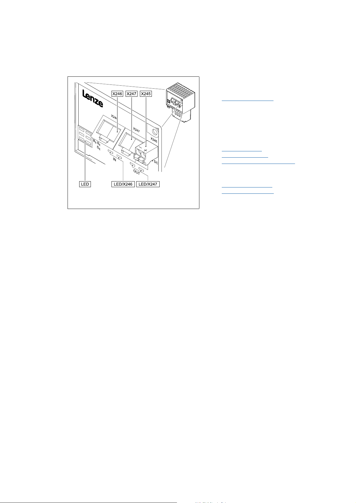
_ _ _ _ _ _ _ _ _ _ _ _ _ _ _ _ _ _ _ _ _ _ _ _ _ _ _ _ _ _ _ _ _ _ _ _ _ _ _ _ _ _ _ _ _ _ _ _ _ _ _ _ _ _ _ _ _ _ _ _ _ _ _ _
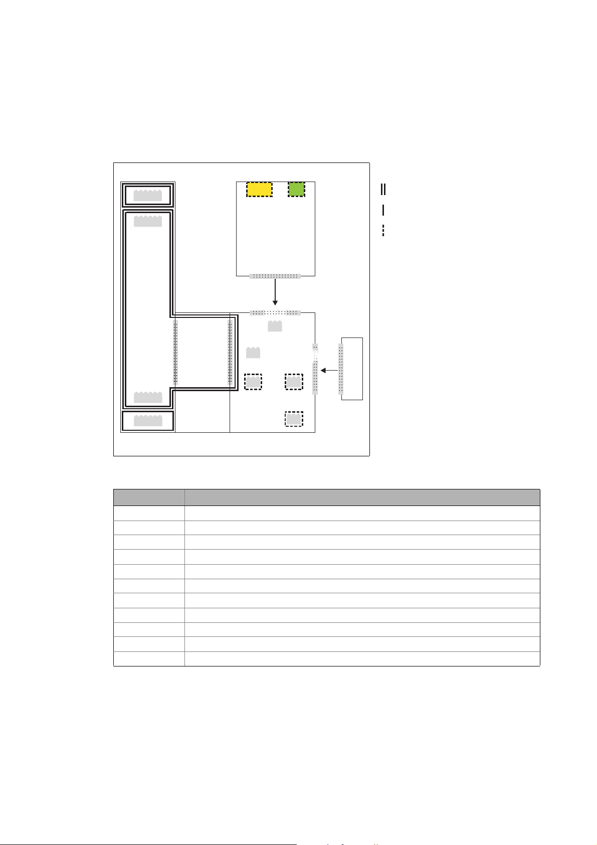
3.4 Terminals and interfaces
X245 External voltage supply of the communication
module
2-pole plug connector with spring connection
[3-2] E84AYCET communication module (EtherCAT)
E84YCET001C
External voltage supply
X246 EtherCAT input (IN)
X247 EtherCAT output (OUT)
• RJ45 sockets according to IEC/EN 60603-7
• with 2 LED status displays each for
diagnostics
Network topology
EtherCAT connection
Status displays at X246 and X247
5 LED status displays for diagnostics
MS
Module status displays
ME
BS
Fieldbus status displays
BE
DE
( 31)
( 26)
( 27)
( 88)
( 85)
( 86)
14
Lenze · E84AYCET communication module (EtherCAT) · Communication Manual · DMS 5.0 EN · 05/2013 · TD17
Page 15
4Technical data
4.1 General data and operating conditions
_ _ _ _ _ _ _ _ _ _ _ _ _ _ _ _ _ _ _ _ _ _ _ _ _ _ _ _ _ _ _ _ _ _ _ _ _ _ _ _ _ _ _ _ _ _ _ _ _ _ _ _ _ _ _ _ _ _ _ _ _ _ _ _
4 Technical data
4.1 General data and operating conditions
Area Values
Order designation E84AYCET
Communication profile EtherCAT
Supported device profile and mailbox
protocol
Communication medium S/FTP (Screened Foiled Twisted Pair, ISO/IEC 11801 or EN 50173), CAT 5e
Interface for communication RJ45: Standard Ethernet (in accordance with IEEE 802.3), 100Base-TX (Fast
Network topology Line, switch
Bus device type EtherCAT slave
Number of nodes Max. 65535 ( in the entire network )
Max. cable length between two
EtherCAT nodes
Vendor ID [hex] 0x3B
Product ID Depending on the standard device used (see chapter Automatic device
Revision ID Depending on the software version of the communication module (see
Baud rate 100 Mbps, full duplex
Cycle times 1 ms or an integer multiple of 1 ms,
Voltage supply External supply via a separate power supply unit
Conformity, approvals CE
CANopen over EtherCAT (CoE)
Ethernet)
100 m (typically)
identification ( 35)).
chapter Identification
max. 15 ms if "Distributed clocks" (DC) are used
• "+": V = 24 V DC (20.4 V - 0 % ... 28.8 V + 0 %), I = 140 mA
• "-": Reference potential for external voltage supply
UL
(see hardware manual "Inverter Drives 8400")
( 12)).
"Inverter Drives 8400" Hardware Manual
Here you can find the ambient conditions and information on the electromagnetic
compatibility (EMC) which also apply to the communication module.
Lenze · E84AYCET communication module (EtherCAT) · Communication Manual · DMS 5.0 EN · 05/2013 · TD17 15
Page 16

4Technical data
4.2 Protective insulation
_ _ _ _ _ _ _ _ _ _ _ _ _ _ _ _ _ _ _ _ _ _ _ _ _ _ _ _ _ _ _ _ _ _ _ _ _ _ _ _ _ _ _ _ _ _ _ _ _ _ _ _ _ _ _ _ _ _ _ _ _ _ _ _
4.2 Protective insulation
Danger!
Dangerous voltage
If Inverter Drives 8400 are used on a phase earthed mains with a rated mains voltage
≥ 400 V, external measures need to be implemented in order to provide reliable
protection against accidental contact.
Possible consequences:
Death or severe injury
Protective measures:
If protection against accidental contact is required for the control terminals of the
inverter and the connections of the plugged device modules, ...
• a double isolating distance must be available.
• the components to be connected must be provided with a second isolating distance.
Note!
The protective insulation provided in Inverter Drives 8400 is realised in accordance with
EN 61800-5-1.
16
Lenze · E84AYCET communication module (EtherCAT) · Communication Manual · DMS 5.0 EN · 05/2013 · TD17
Page 17
4Technical data
4.2 Protective insulation
_ _ _ _ _ _ _ _ _ _ _ _ _ _ _ _ _ _ _ _ _ _ _ _ _ _ _ _ _ _ _ _ _ _ _ _ _ _ _ _ _ _ _ _ _ _ _ _ _ _ _ _ _ _ _ _ _ _ _ _ _ _ _ _
The following illustration ...
• shows the arrangement of the terminal strips and the separate potential areas of the inverter.
• serves to determine the decisive protective insulation between two terminals located in
differently insulated separate potential areas.
Bus
Ext. DC
X106X106X106X101
X100X100
MCI
X6
X6
X3
X3
X5
X4
X4
X5
X105X105
X106X106X106X106
[4-1] Protective insulation in accordance with EN61800-5-1
X1X1
Reinforced insulation
Basic insulation
Functional insulation
MMI
E84YCXX007
Terminal strip Connection
X100 Mains / DC bus connection
X101 Relay contact
X105 Motor/brake resistor
X106 Motor PTC
X1 System bus (CAN)
X3 Analog inputs/outputs
X4 Digital outputs
X5 Digital inputs
X6 Diagnostics
MCI Slot for communication module
MMI Slot for memory module
Lenze · E84AYCET communication module (EtherCAT) · Communication Manual · DMS 5.0 EN · 05/2013 · TD17 17
Page 18

4Technical data
4.2 Protective insulation
_ _ _ _ _ _ _ _ _ _ _ _ _ _ _ _ _ _ _ _ _ _ _ _ _ _ _ _ _ _ _ _ _ _ _ _ _ _ _ _ _ _ _ _ _ _ _ _ _ _ _ _ _ _ _ _ _ _ _ _ _ _ _ _
Example
Which type of protective insulation is used between the bus terminal of the device module in slot
MCI and the mains terminal X100?
The separate potential area with the better protective insulation is decisive.
• The separate potential area of the bus terminal of the device module has a "basic insulation".
• The separate potential area of the mains terminal has a "reinforced insulation".
Result: The insulation between the X100 mains terminal and the bus terminal is of the "reinforced
insulation" type.
18
Lenze · E84AYCET communication module (EtherCAT) · Communication Manual · DMS 5.0 EN · 05/2013 · TD17
Page 19

4Technical data
4.3 Protocol data
_ _ _ _ _ _ _ _ _ _ _ _ _ _ _ _ _ _ _ _ _ _ _ _ _ _ _ _ _ _ _ _ _ _ _ _ _ _ _ _ _ _ _ _ _ _ _ _ _ _ _ _ _ _ _ _ _ _ _ _ _ _ _ _
4.3 Protocol data
Area Values
Process data words 1 ... 16 process data words per direction
(max. 32 bytes, 16 bits/word)
Parameter data (mailbox size for CoE
transfer)
4.4 Communication time
The communication time is the time between the start of a request and the arrival of the
corresponding response.
The communication times in the EtherCAT network depend on the ...
• processing time in the inverter;
• telegram runtime (baud rate / telegram length).
Max. 128 bytes
processing time within the inverter
Data Processing time
Process data for synchronised
operation
Process data for non-synchronised
operation
Parameter data approx. 30msProcessing time
0.2 ms Processing time in the module
+ 1 ... x ms Runtime of the application task of the technology
application used (tolerance)
2 ms Processing time in the module
+ 1 ... x ms Runtime of the application task of the technology
application used (tolerance)
+ 20 ms Tolerance (typical)
Some codes may require a longer processing time (see
software manual/online help for the Inverter Drive 8400).
Lenze · E84AYCET communication module (EtherCAT) · Communication Manual · DMS 5.0 EN · 05/2013 · TD17 19
Page 20

4Technical data
4.5 Dimensions
_ _ _ _ _ _ _ _ _ _ _ _ _ _ _ _ _ _ _ _ _ _ _ _ _ _ _ _ _ _ _ _ _ _ _ _ _ _ _ _ _ _ _ _ _ _ _ _ _ _ _ _ _ _ _ _ _ _ _ _ _ _ _ _
4.5 Dimensions
E84YCET001B
[4-2] Dimensions
Type Dimensions [mm]
a b c c1
E84AYCET 67 50 57 8
20
Lenze · E84AYCET communication module (EtherCAT) · Communication Manual · DMS 5.0 EN · 05/2013 · TD17
Page 21

5 Installation
_ _ _ _ _ _ _ _ _ _ _ _ _ _ _ _ _ _ _ _ _ _ _ _ _ _ _ _ _ _ _ _ _ _ _ _ _ _ _ _ _ _ _ _ _ _ _ _ _ _ _ _ _ _ _ _ _ _ _ _ _ _ _ _
5 Installation
Stop!
Electrostatic discharge
Electronic components in the communication module can be damaged or destroyed by
electrostatic discharge.
Possible consequences:
• The communication module is defective.
• Fieldbus communication is faulty or not possible.
Protective measures:
Before touching the module, make sure that you are free of electrostatic charge.
Lenze · E84AYCET communication module (EtherCAT) · Communication Manual · DMS 5.0 EN · 05/2013 · TD17 21
Page 22
5 Installation
5.1 Mechanical installation
_ _ _ _ _ _ _ _ _ _ _ _ _ _ _ _ _ _ _ _ _ _ _ _ _ _ _ _ _ _ _ _ _ _ _ _ _ _ _ _ _ _ _ _ _ _ _ _ _ _ _ _ _ _ _ _ _ _ _ _ _ _ _ _
5.1 Mechanical installation
The communication module can be plugged into the MCI slot or removed while the frequency
inverter is switched on. When the module is plugged in, it is recognised automatically and checked
for plausibility regarding its function and version.
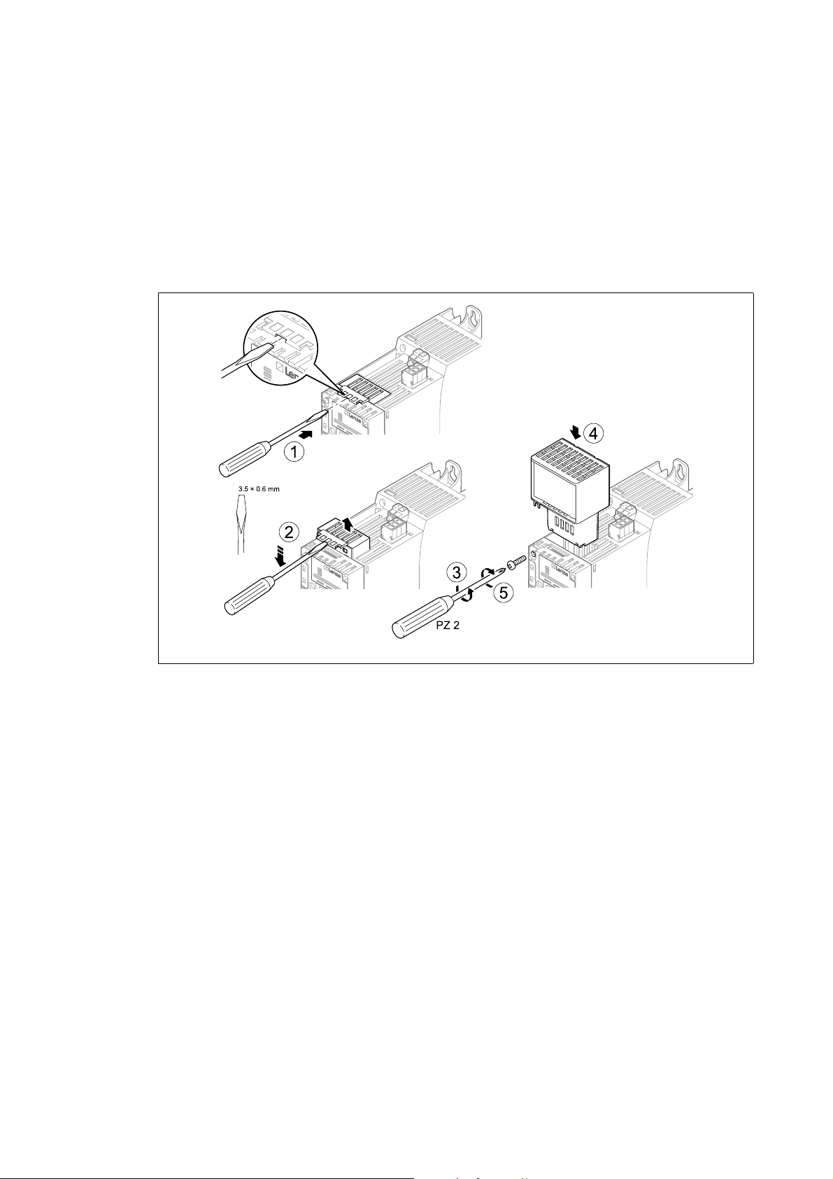
5.1.1 Mounting for standard devices 0.25 kW and 0.37 kW
E84YCPM002D
[5-1] Mounting for standard devices 0.25 kW and 0.37 kW
Mounting steps
1. Use a screwdriver to lever out the cover of the MCI slot of the standard device and remove
it (1, 2).
2. Loosen the securing screw for the communication module at the standard device (3).
3. Insert the communication module into the MCI slot of the standard device (4).
4. Tighten the securing screw again (5).
22
Lenze · E84AYCET communication module (EtherCAT) · Communication Manual · DMS 5.0 EN · 05/2013 · TD17
Page 23
5 Installation
5.1 Mechanical installation
_ _ _ _ _ _ _ _ _ _ _ _ _ _ _ _ _ _ _ _ _ _ _ _ _ _ _ _ _ _ _ _ _ _ _ _ _ _ _ _ _ _ _ _ _ _ _ _ _ _ _ _ _ _ _ _ _ _ _ _ _ _ _ _
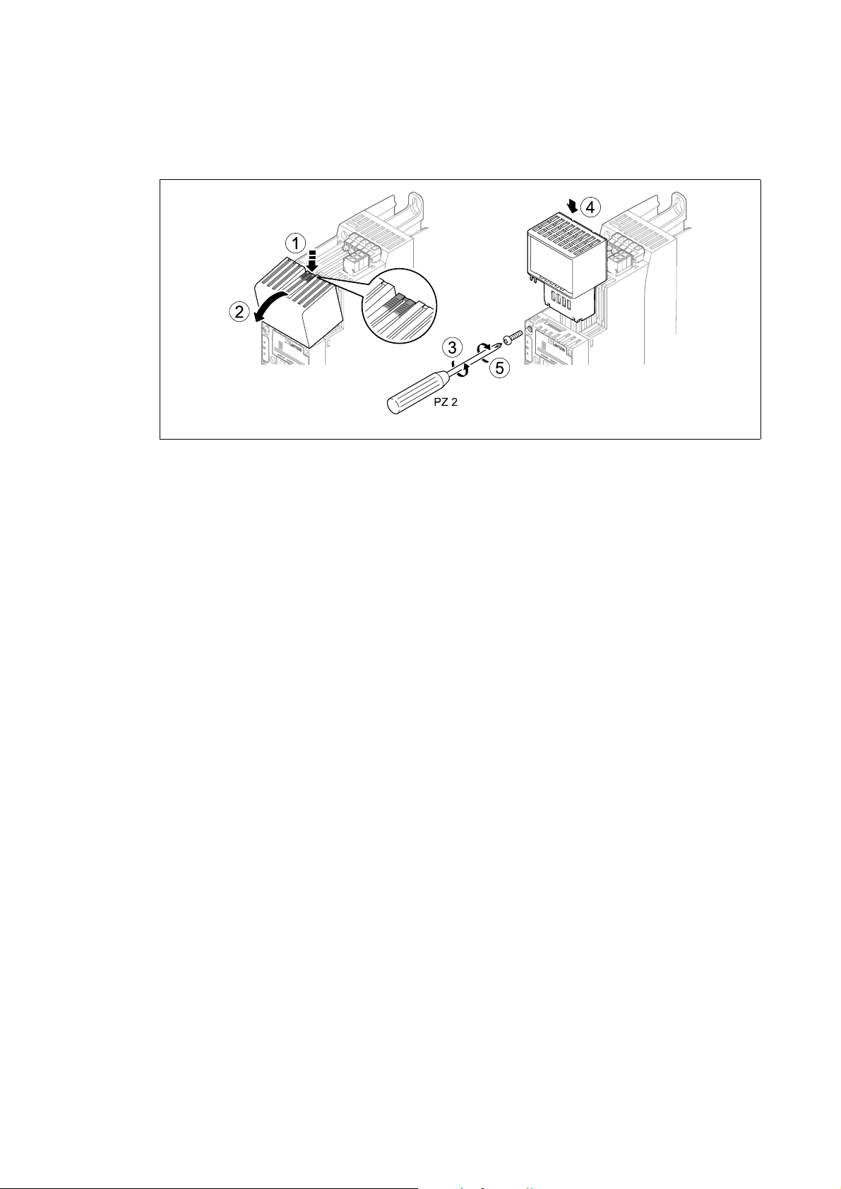
5.1.2 Mounting for standard devices from 0.55 kW onwards
E84YCPM002A
[5-2] Mounting for standard devices from 0.55 kW onwards
Mounting steps
1. Slightly impress the pressure surface of the top side of the MCI slot cover of the standard
device (1).
2. Bend the cover forward and remove it from the standard device (2).
3. Loosen the securing screw for the communication module at the standard device (3).
4. Insert the communication module into the MCI slot of the standard device (4).
5. Tighten the securing screw again (5).
Lenze · E84AYCET communication module (EtherCAT) · Communication Manual · DMS 5.0 EN · 05/2013 · TD17 23
Page 24
5 Installation
5.1 Mechanical installation
_ _ _ _ _ _ _ _ _ _ _ _ _ _ _ _ _ _ _ _ _ _ _ _ _ _ _ _ _ _ _ _ _ _ _ _ _ _ _ _ _ _ _ _ _ _ _ _ _ _ _ _ _ _ _ _ _ _ _ _ _ _ _ _
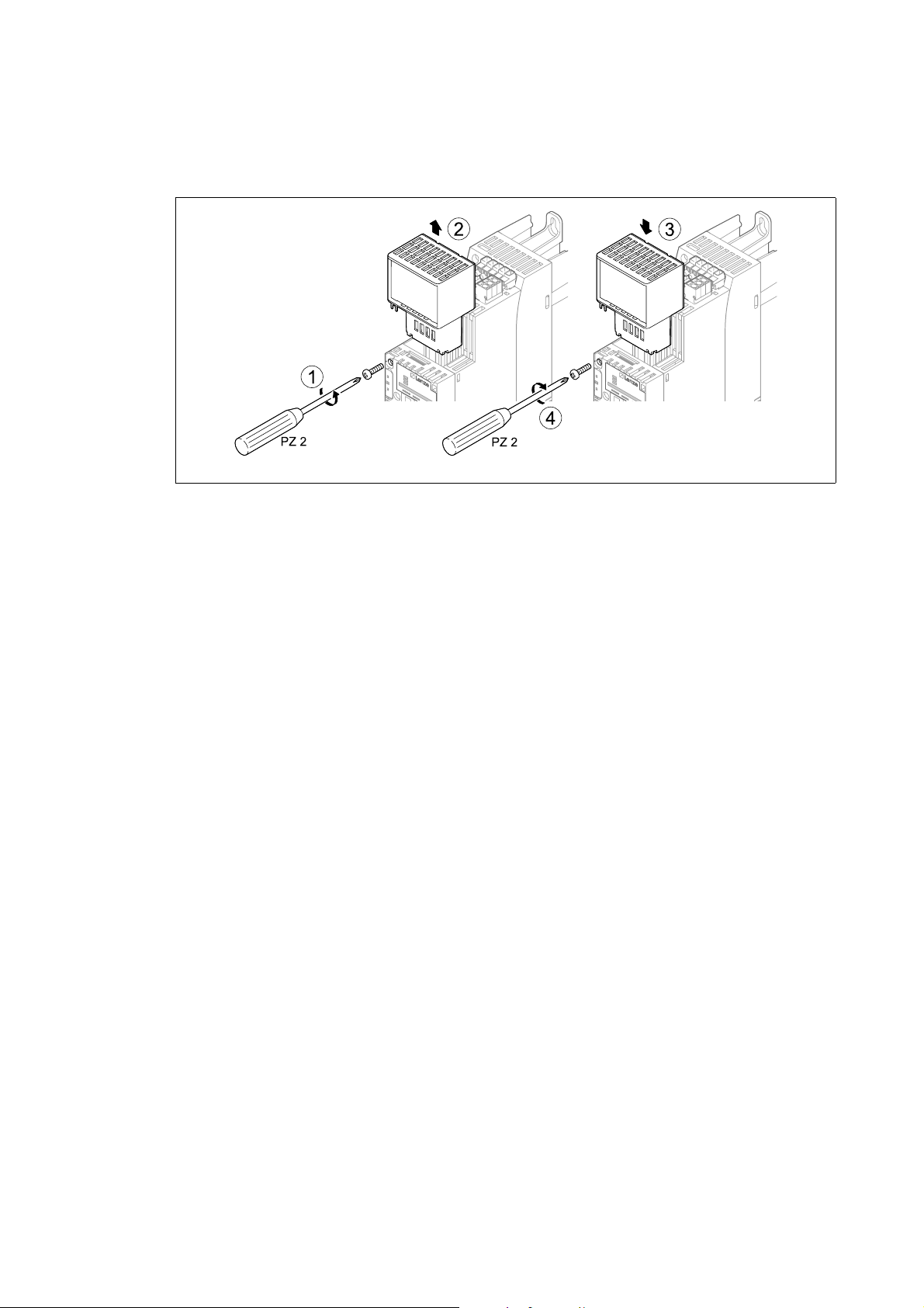
5.1.3 Replacing the communication module
E84YCPM002B
[5-3] Replacing the communication module
Mounting steps
1. Loosen the securing screw for the communication module at the standard device (1).
2. Remove the communication module from the MCI slot of the standard device (2).
3. Insert the new communication module into the MCI slot of the standard device (3).
4. Tighten the securing screw again (4).
24
Lenze · E84AYCET communication module (EtherCAT) · Communication Manual · DMS 5.0 EN · 05/2013 · TD17
Page 25

5 Installation
5.2 Electrical installation
_ _ _ _ _ _ _ _ _ _ _ _ _ _ _ _ _ _ _ _ _ _ _ _ _ _ _ _ _ _ _ _ _ _ _ _ _ _ _ _ _ _ _ _ _ _ _ _ _ _ _ _ _ _ _ _ _ _ _ _ _ _ _ _
5.2 Electrical installation
Documentation for the standard device, control system, plant/machine
Observe the notes and wiring instructions stated.
5.2.1 EMC-compliant wiring
In typical systems, standard shielding is sufficient for Ethernet cables.
However, in environments with a very high level of interference, EMC resistance can be improved
by earthing both sides of the cable shield as well.
For this purpose, observe the following notes:
1. Remove the plastic sheath of the cable on a length of 2 cm.
2. Fasten the cable shield to the shield support of the basic device.
Lenze · E84AYCET communication module (EtherCAT) · Communication Manual · DMS 5.0 EN · 05/2013 · TD17 25
Page 26
5 Installation
5.2 Electrical installation
_ _ _ _ _ _ _ _ _ _ _ _ _ _ _ _ _ _ _ _ _ _ _ _ _ _ _ _ _ _ _ _ _ _ _ _ _ _ _ _ _ _ _ _ _ _ _ _ _ _ _ _ _ _ _ _ _ _ _ _ _ _ _ _
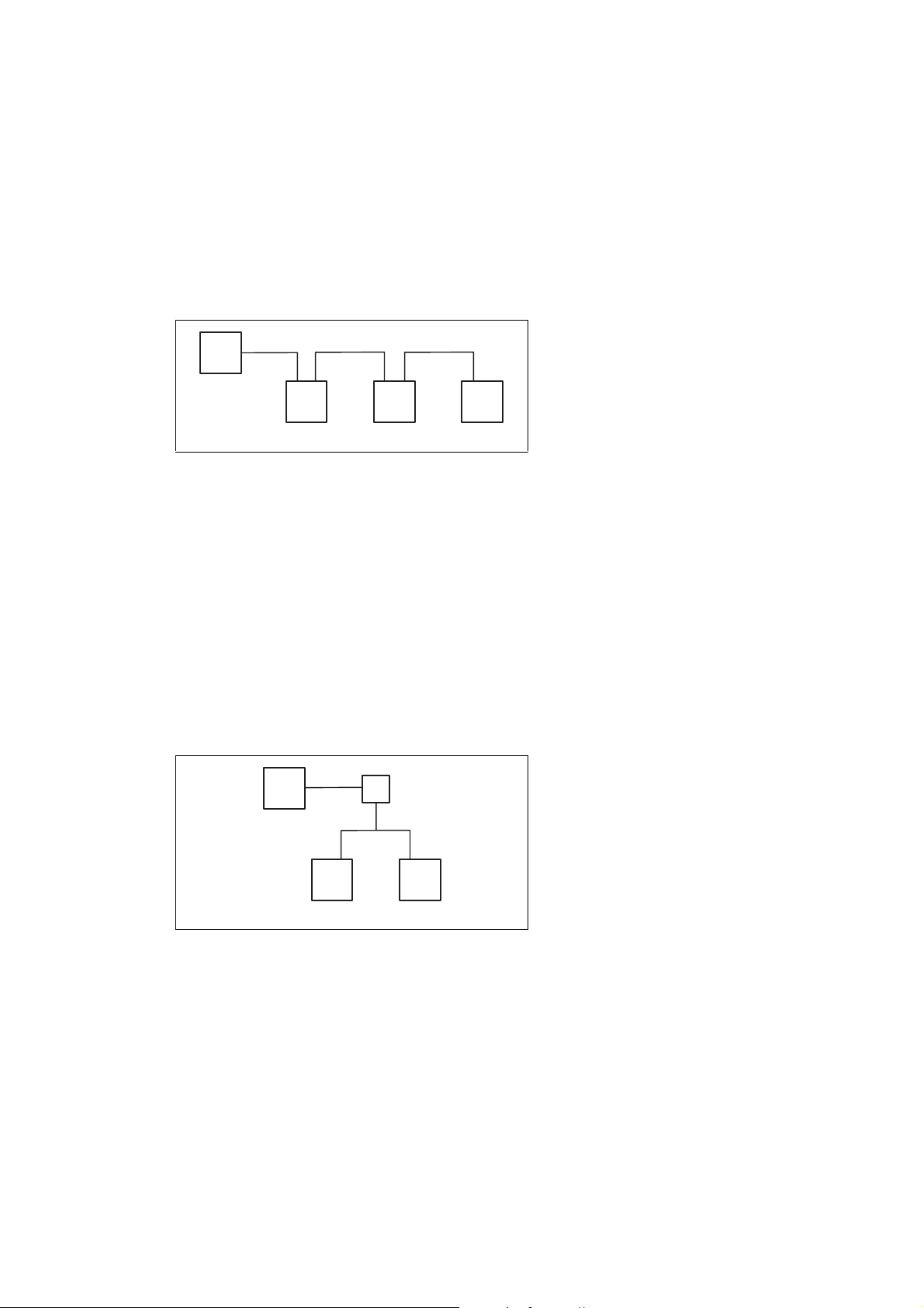
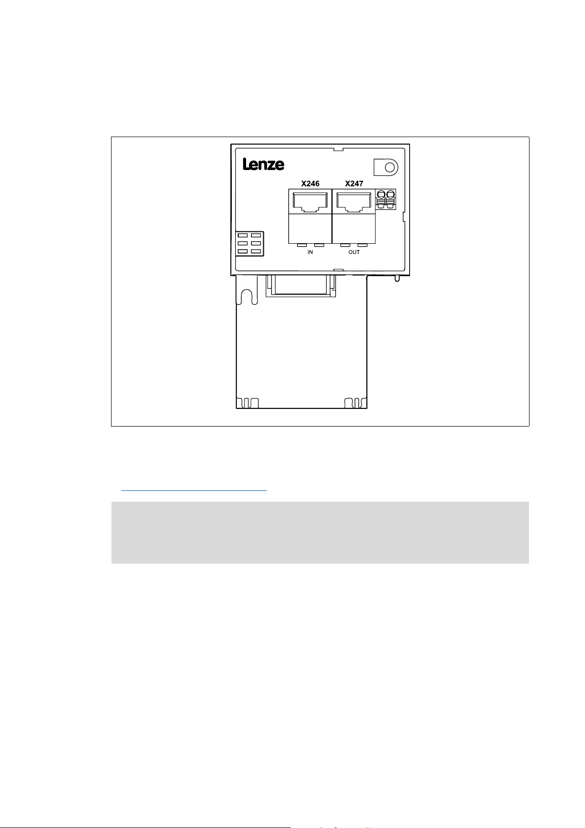
5.2.2 Network topology
An EtherCAT frame is sent through a pair of wires from the master to the slaves. The frame is
forwarded from slave to slave until it has passed through all the devices. Finally, the last slave
returns the frame to the master through a second pair of wires. In this way, EtherCAT always forms
a logic ring topology, irrespective of the topology used.
Line topology
M = master
M
IN
INOUT
INOUT
SD = slave device
SD
[5-4] Line topology
The devices are interconnected successively.
In order to ensure trouble-free operation, it is required to assign and wire the EtherCAT inputs (IN)
and EtherCAT outputs (OUT) correctly.
The receiving line is plugged into socket X246 (IN), the forwarding line into socket X247 (OUT).
The direction of data transmission is from the master to the slaves.
SD
SD
E94AYCET006
Tip!
Switch topology
The termination of the last EtherCAT node is effected automatically by the slave.
M = master
M
M
S
IN IN
S = switch
SD = slave device
[5-5] Switch topology
26
SD
The wiring can also be carried out in a star structure via an appropriate switch. For this, observe the
additional runtimes.
Lenze · E84AYCET communication module (EtherCAT) · Communication Manual · DMS 5.0 EN · 05/2013 · TD17
SD
E94AYCET007
Page 27
5 Installation
5.2 Electrical installation
_ _ _ _ _ _ _ _ _ _ _ _ _ _ _ _ _ _ _ _ _ _ _ _ _ _ _ _ _ _ _ _ _ _ _ _ _ _ _ _ _ _ _ _ _ _ _ _ _ _ _ _ _ _ _ _ _ _ _ _ _ _ _ _
5.2.3 EtherCAT connection
EtherCAT is connected via the RJ45 sockets X246 (IN) and X247 (OUT).
[5-6] EtherCAT connection
A standard Ethernet patch cable is suitable for connecting the communication module to the
EtherCAT fieldbus.
Specification of the Ethernet cable
( 29)
Note!
In order to prevent damage to the RJ45 socket, plug or remove the Ethernet cable
connector straight (at a right angle) into/from the socket.
E84YCET001E
Lenze · E84AYCET communication module (EtherCAT) · Communication Manual · DMS 5.0 EN · 05/2013 · TD17 27
Page 28

5 Installation
5.2 Electrical installation
_ _ _ _ _ _ _ _ _ _ _ _ _ _ _ _ _ _ _ _ _ _ _ _ _ _ _ _ _ _ _ _ _ _ _ _ _ _ _ _ _ _ _ _ _ _ _ _ _ _ _ _ _ _ _ _ _ _ _ _ _ _ _ _
Pin assignment of the RJ45 sockets
RJ45 socket Pin Signal
1Tx +
2Tx -
3Rx +
4-
5-
6Rx -
E94AYCXX004C
7-
8-
Tip!
The EtherCAT interfaces are provided with an auto MDIX function. This function adjusts the
polarity of the RJ45 interfaces so that a connection can be established irrespective of the
polarity of the opposite EtherCAT interface and irrespective of the type of cable used
(standard patch cable or crossover cable).
28
Lenze · E84AYCET communication module (EtherCAT) · Communication Manual · DMS 5.0 EN · 05/2013 · TD17
Page 29
5 Installation
5.2 Electrical installation
_ _ _ _ _ _ _ _ _ _ _ _ _ _ _ _ _ _ _ _ _ _ _ _ _ _ _ _ _ _ _ _ _ _ _ _ _ _ _ _ _ _ _ _ _ _ _ _ _ _ _ _ _ _ _ _ _ _ _ _ _ _ _ _
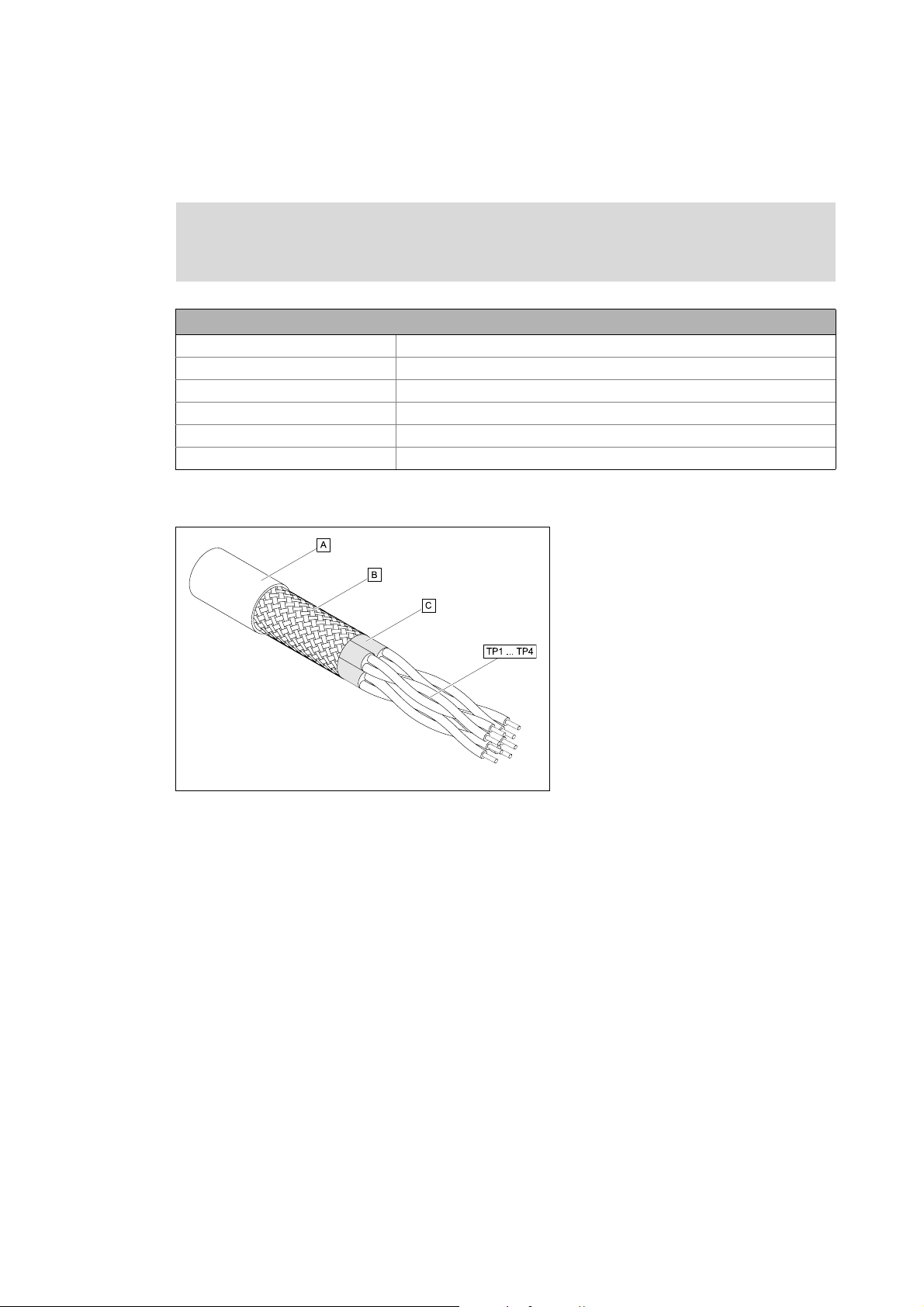
5.2.4 Specification of the Ethernet cable
Note!
Only use cables that correspond to the given specifications.
Specification of the Ethernet cable
Ethernet standard Standard Ethernet (acc. to IEEE 802.3), 100Base-TX (Fast Ethernet)
Cable type S/FTP (Screened Foiled Twisted Pair, ISO/IEC 11801 or EN 50173), CAT 5e
Damping 23.2 dB (for 100 MHz and 100 m each)
Crosstalk damping 24 dB (for 100 MHz and 100 m each)
Return loss 10 dB (100 m each)
Surge impedance 100 Ω
Structure of the Ethernet cable
[5-7] Structure of the Ethernet cable (S/FTP, CAT 5e)
E94YCEP016
A Cable insulation
B Braid
C Foil shielding
TP1
Twisted core pairs 1 ... 4
...
TP4
Lenze · E84AYCET communication module (EtherCAT) · Communication Manual · DMS 5.0 EN · 05/2013 · TD17 29
Page 30
5 Installation
5.2 Electrical installation
_ _ _ _ _ _ _ _ _ _ _ _ _ _ _ _ _ _ _ _ _ _ _ _ _ _ _ _ _ _ _ _ _ _ _ _ _ _ _ _ _ _ _ _ _ _ _ _ _ _ _ _ _ _ _ _ _ _ _ _ _ _ _ _
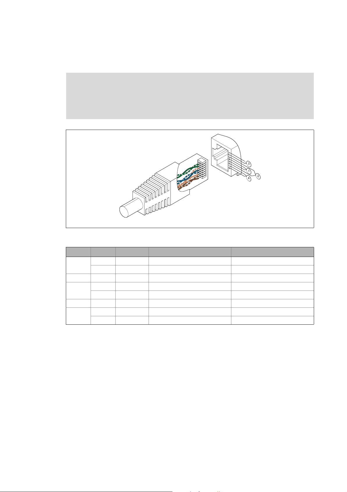
Colour code of the Ethernet cable
Note!
Wiring and colour code are standardised in EIA/TIA 568A/568B.
The use of 4-pole Ethernet cables according to industrial standard is permissible. The
cable type only connects the assigned pins 1, 2, 3 and 6.
E94YCEI004A
[5-8] Ethernet plugs in accordance with EIA/TIA 568A/568B
Pair Pin Signal EIA/TIA 568A EIA/TIA 568B
3 1 Tx + white / green white / orange
2 Tx - green orange
2 3 Rx + white / orange white / green
1 4 blue blue
5 white / blue blue / white
2 6 Rx - orange green
4 7 white / brown white / brown
8brown brown
30
Lenze · E84AYCET communication module (EtherCAT) · Communication Manual · DMS 5.0 EN · 05/2013 · TD17
Page 31

5 Installation
5.2 Electrical installation
_ _ _ _ _ _ _ _ _ _ _ _ _ _ _ _ _ _ _ _ _ _ _ _ _ _ _ _ _ _ _ _ _ _ _ _ _ _ _ _ _ _ _ _ _ _ _ _ _ _ _ _ _ _ _ _ _ _ _ _ _ _ _ _
5.2.5 External voltage supply
The communication module can be supplied externally with voltage via separate supply cables at
the 2-pole plug connector X245.
Note!
With external voltage supply, always use a separate power supply unit, safely separated
to EN 61800-5-1 in every control cabinet (SELV/PELV).
External voltage supply of the communication module is necessary if the bus communication is to
be continued in the event of a failure of the supply of the standard device.
Access to parameters of a standard device disconnected from the mains is not possible.
Wiring plug connector X245
Stop!
Only wire the plug connector if the standard device is disconnected from the mains.
[5-9] Wiring of the 2-pole plug connector with spring connection
How to wire the plug connector with spring connection:
1. Place a screwdriver in the notch beneath the contact slot and keep it pressed.
2. Insert the supply cable in the contact slot.
E84AYCXX010
3. Remove the screwdriver from the notch.
Lenze · E84AYCET communication module (EtherCAT) · Communication Manual · DMS 5.0 EN · 05/2013 · TD17 31
Page 32

5 Installation
5.2 Electrical installation
_ _ _ _ _ _ _ _ _ _ _ _ _ _ _ _ _ _ _ _ _ _ _ _ _ _ _ _ _ _ _ _ _ _ _ _ _ _ _ _ _ _ _ _ _ _ _ _ _ _ _ _ _ _ _ _ _ _ _ _ _ _ _ _
Assignment of the X245 plug connector
Designation Description
+ U = 24 V DC (20.4 V - 0 % ... 28.8 V + 0 %)
I = 140 mA
- Reference potential for the external voltage supply
Terminal data
Area Values
Electrical connection 2-pole plug connector with spring connection
Possible connections Fixed:
0.2 ... 1.5 mm
Flexible:
Without wire end ferrule
0.2 ... 1.5 mm
2
(AWG 24 ... 16)
2
(AWG 24 ... 16)
With wire end ferrule, without plastic sleeve
0.2 ... 1.5 mm
With wire end ferrule, with plastic sleeve
0.2 ... 1.5 mm
Stripping length 10 mm
2
(AWG 24 ... 16)
2
(AWG 24 ... 16)
32
Lenze · E84AYCET communication module (EtherCAT) · Communication Manual · DMS 5.0 EN · 05/2013 · TD17
Page 33

6 Commissioning
6.1 Before initial switch-on
_ _ _ _ _ _ _ _ _ _ _ _ _ _ _ _ _ _ _ _ _ _ _ _ _ _ _ _ _ _ _ _ _ _ _ _ _ _ _ _ _ _ _ _ _ _ _ _ _ _ _ _ _ _ _ _ _ _ _ _ _ _ _ _
6 Commissioning
During commissioning, plant-specific data such as motor parameters, operating parameters,
responses, and parameters for fieldbus communication are defined for the inverter. Lenze devices
use codes for this purpose.
The codes of the inverter and for communication are saved to the memory module in a non-volatile
data set.
In addition, there are codes for diagnosing and monitoring the stations.
Parameters of the communication module
6.1 Before initial switch-on
Stop!
Before you switch on the Inverter Drive 8400 and the communication module for the
first time, check the entire wiring for completeness, short circuit and earth fault.
( 97)
Lenze · E84AYCET communication module (EtherCAT) · Communication Manual · DMS 5.0 EN · 05/2013 · TD17 33
Page 34

6 Commissioning
6.2 Configuring the Controller (EtherCAT master)
_ _ _ _ _ _ _ _ _ _ _ _ _ _ _ _ _ _ _ _ _ _ _ _ _ _ _ _ _ _ _ _ _ _ _ _ _ _ _ _ _ _ _ _ _ _ _ _ _ _ _ _ _ _ _ _ _ _ _ _ _ _ _ _
6.2 Configuring the Controller (EtherCAT master)
The Controller (EtherCAT master) must be configured before communication with the
communication module is possible.
In order to configure EtherCAT networks, you always need a configuration software for the
Controller, e.g.:
• Lenze »PLC Designer«
• Beckhoff »TwinCAT«
These are software systems for the programming of control programs, EtherCAT configuration, realtime execution, and diagnostics.
The basic parameters of the communication module are stored in the internal configuration
memory and can be used by the master for the node identification.
For the node search (fieldbus scan), the corresponding device descriptions of the Lenze device family
are used.
6.2.1 Installing device description files
The current XML device description file required for configuring the EtherCAT node can be found in
the download area at:
www.Lenze.com
The Lenze_Inverter_8400_IO_yyyymmdd.xml device description file has to be installed via the
EtherCAT configuration software.
Wildcards in the file name
yyyy Year
mm Month
dd Day
The description file includes all EtherCAT capable devices of the Inverter Drives 8400 series (Inverter
Drives 8400 with EtherCAT V01.xx and V02.xx, 8400 motec with EtherCAT V01.xx).
34
Lenze · E84AYCET communication module (EtherCAT) · Communication Manual · DMS 5.0 EN · 05/2013 · TD17
Page 35

6 Commissioning
6.2 Configuring the Controller (EtherCAT master)
_ _ _ _ _ _ _ _ _ _ _ _ _ _ _ _ _ _ _ _ _ _ _ _ _ _ _ _ _ _ _ _ _ _ _ _ _ _ _ _ _ _ _ _ _ _ _ _ _ _ _ _ _ _ _ _ _ _ _ _ _ _ _ _
6.2.2 Automatic device identification
For a faultless integration of the EtherCAT slaves into a master configuration it is necessary to select
the correct Lenze device in the EtherCAT configuration software.
Each EtherCAT node is identified unambiguously by the configuration software by means of the
product code (equal to the CoE object I-1018.2), the manufacturer's identification mark (0x3B), and
the main software version of the communication module.
Identification
( 12)
Implemented CoE objects
In order that the configuration software select the configuration from the device description file
specific for the EtherCAT node, the product code is automatically set in the identity object. An
update is made after switching off/on the voltage supply.
During initialisation, the product code is transferred to the EtherCAT master. On the basis of this
identification, the master can accept the corresponding settings from the device description.
Product codes for Inverter Drives 8400
The product code defines the following Inverter Drives 8400 in the device description files:
Product code [dec] Meaning
8 4 0 0 2 2 Inverter Drive 8400 StateLine
8 4 0 0 2 3 Inverter Drive 8400 HighLine
8 4 0 0 2 4 Inverter Drive 8400 TopLine
8 4 0 0 2 5 Inverter Drive 8400 TopLine P (with CiA402)
6.2.3 Configuring process data
Inverter Drives 8400 support the configuration of max. 16 process data words (max. 32 bytes) per
direction.
The process data configuration is determined during the initialisation phase of the master (PDO
mapping).
The process data configuration is predefined in the device description file for each application.
The process data length can be adjusted by the user if required.
( 79)
6.2.4 Determining the cycle time
The process data objects (PDO) are transferred cyclically between the EtherCAT master and the
slaves (inverters).
The cycle time is set with the EtherCAT configuration software.
Lenze · E84AYCET communication module (EtherCAT) · Communication Manual · DMS 5.0 EN · 05/2013 · TD17 35
Page 36

6 Commissioning
6.3 Address allocation
_ _ _ _ _ _ _ _ _ _ _ _ _ _ _ _ _ _ _ _ _ _ _ _ _ _ _ _ _ _ _ _ _ _ _ _ _ _ _ _ _ _ _ _ _ _ _ _ _ _ _ _ _ _ _ _ _ _ _ _ _ _ _ _
6.3 Address allocation
The EtherCAT nodes are normally addressed via a fixed 16-bit address defined by the EtherCAT
master. During start-up, the master assigns this address to each node, depending on the physical
order in the EtherCAT network. The address is not saved and is lost when the device is switched off.
Via the Station alias address input field you can assign a fixed address to the EtherCAT slave.
Note!
• The station alias address must be unambiguous and may only be assigned once
within the EtherCAT network.
• Use the same station alias address in the EtherCAT master and in the slave.
Valid address range: 0 … 32767
• Address 0 means that no station alias address is assigned.
• Impermissible addresses are marked in red in the input field.
• The address is written to code C13899
In addition, specify the use of the fixed addressing on the master.
The address assigned by the master is displayed under code C13864
.
.
36
Lenze · E84AYCET communication module (EtherCAT) · Communication Manual · DMS 5.0 EN · 05/2013 · TD17
Page 37

6 Commissioning
6.4 Synchronisation with "Distributed Clocks" (DC)
_ _ _ _ _ _ _ _ _ _ _ _ _ _ _ _ _ _ _ _ _ _ _ _ _ _ _ _ _ _ _ _ _ _ _ _ _ _ _ _ _ _ _ _ _ _ _ _ _ _ _ _ _ _ _ _ _ _ _ _ _ _ _ _
6.4 Synchronisation with "Distributed Clocks" (DC)
The "Distributed clocks" (DC) functionality enables exact time synchronisation for applications in
which several axes perform a coordinated movement simultaneously. Data are incorporated
synchronously with the PLC program. During DC synchronisation, all slaves are synchronised with a
reference clock, the so-called "DC master".
Note!
• DC synchronisation is absolutely required for Motion applications.
• DC synchronisation can also be used for Logic applications.
• Not all slaves support the DC functionality.
• On order to be able to use the DC functionality, the first slave connected to the
EtherCAT master (e.g. Lenze Controller) must have DC master capability.
When further slaves are connected, DC-capable and non-DC-capable devices can be
mixed.
• The first EtherCAT slave after the Lenze Controller must
supplies the other EtherCAT nodes (incl. Controller) with the exact time.
be the DC master that
[6-1] Example: "Distributed clocks" in the EtherCAT bus system with Lenze Controller 3231 C
The DC synchronisation is set with the EtherCAT configuration software.
"Control technology EtherCAT" communication manual
Here you can find some detailed information about the EtherCAT configuration and the
commissioning of Lenze devices in the EtherCAT network.
Lenze · E84AYCET communication module (EtherCAT) · Communication Manual · DMS 5.0 EN · 05/2013 · TD17 37
Page 38

6 Commissioning
6.4 Synchronisation with "Distributed Clocks" (DC)
_ _ _ _ _ _ _ _ _ _ _ _ _ _ _ _ _ _ _ _ _ _ _ _ _ _ _ _ _ _ _ _ _ _ _ _ _ _ _ _ _ _ _ _ _ _ _ _ _ _ _ _ _ _ _ _ _ _ _ _ _ _ _ _
6.4.1 DC configuration in the master
By default, the application of the DC synchronisation is deactivated in the device description ( 34).
Parameterise the DC synchronisation in the EtherCAT configuration software (»PLC Designer«,
»TwinCAT«).
Set the synchronisation cycle time in the master. It is mainly defined by the processing time of the
master and the slaves.
Note!
The synchronisation cycle time ...
• must be an integer multiple of 1 ms;
• may be maximally 15 ms.
6.4.2 DC configuration in the Inverter Drive 8400 (slave)
Note!
The settings of the parameter sync cycle time (C01121), sync phase position (C01122),
sync tolerance (C01123) and sync PLL increment (C01124) common for the Lenze system
bus (CAN) cannot be made for EtherCAT. These values are automatically calculated by
the EtherCAT communication module and set internally in the inverter.
In order to use the DC synchronisation in the Inverter Drive 8400, select the sync source by means
of the standard device code C01120
Selection 4: MCI (synchronisation via MCI (communication module))
:
38
Lenze · E84AYCET communication module (EtherCAT) · Communication Manual · DMS 5.0 EN · 05/2013 · TD17
Page 39

6 Commissioning
6.4 Synchronisation with "Distributed Clocks" (DC)
_ _ _ _ _ _ _ _ _ _ _ _ _ _ _ _ _ _ _ _ _ _ _ _ _ _ _ _ _ _ _ _ _ _ _ _ _ _ _ _ _ _ _ _ _ _ _ _ _ _ _ _ _ _ _ _ _ _ _ _ _ _ _ _
6.4.3 Response of the Lenze EtherCAT nodes during start-up
Code C13883 indicates whether the DC synchronisation for the communication module has been
activated.
If the DC synchronisation is used, the communication module only changes to the "Operational"
state when the standard device has adapted its phase position to the DC signal. This process may
take several seconds.
Note!
• If the communication module does not change to the "Operational" state, there might
be an error in the configuration or in the EtherCAT wiring.
• The communication module compares the cycle time defined by the EtherCAT master
to the internal processing time (1 ms) of the standard device. The synchronisation
cycle time in the master must be identical with or an integer multiple of 1 ms.
• Furthermore it is checked whether the sync source selection in standard device code
C01120
• Further information can be found in the status information or emergency messages
of the master.
is correct.
The state of the standard device synchronicity is displayed under code C13884
.
Lenze · E84AYCET communication module (EtherCAT) · Communication Manual · DMS 5.0 EN · 05/2013 · TD17 39
Page 40

6 Commissioning
6.5 Establishing an online connection with the »Engineer«
_ _ _ _ _ _ _ _ _ _ _ _ _ _ _ _ _ _ _ _ _ _ _ _ _ _ _ _ _ _ _ _ _ _ _ _ _ _ _ _ _ _ _ _ _ _ _ _ _ _ _ _ _ _ _ _ _ _ _ _ _ _ _ _
6.5 Establishing an online connection with the »Engineer«
With the »Engineer« you can establish an online connection to the individual field devices.
When an online connection has been established, you can for instance carry out parameter settings
directly in the field device or diagnose the field device.
Stop!
If parameters in the »Engineer« are changed while the Engineer is connected online to
the field device, the changes are directly accepted to the device!
Note!
To go online, the EtherCAT bus at least has to be in the "Pre-Operational" state.
The functions for establishing/cancelling an online connection in the »Engineer« can be executed
via the Online menu:
Menu command Shortcut
Online Go online <F4>
Online Set communication path and go online
Configuring a bus connection:
• Gateway Controller -> configure EtherCAT
• Gateway Controller -> configure EtherCAT ADS (Beckhoff)
Online Go offline <Shift>+<F4>
( 41)
( 43)
Documentation for the Lenze »Engineer«
Here you'll find further detailed information about how to establish an online
connection.
40
Lenze · E84AYCET communication module (EtherCAT) · Communication Manual · DMS 5.0 EN · 05/2013 · TD17
Page 41

6 Commissioning
6.5 Establishing an online connection with the »Engineer«
_ _ _ _ _ _ _ _ _ _ _ _ _ _ _ _ _ _ _ _ _ _ _ _ _ _ _ _ _ _ _ _ _ _ _ _ _ _ _ _ _ _ _ _ _ _ _ _ _ _ _ _ _ _ _ _ _ _ _ _ _ _ _ _
6.5.1 Gateway Controller -> configure EtherCAT
The Lenze Controller provides a gateway function to establish an online connection to a field device
via EtherCAT.
[6-2] Example: EtherCAT bus system with a Lenze Controller 3231 C as gateway
Lenze · E84AYCET communication module (EtherCAT) · Communication Manual · DMS 5.0 EN · 05/2013 · TD17 41
Page 42

6 Commissioning
6.5 Establishing an online connection with the »Engineer«
_ _ _ _ _ _ _ _ _ _ _ _ _ _ _ _ _ _ _ _ _ _ _ _ _ _ _ _ _ _ _ _ _ _ _ _ _ _ _ _ _ _ _ _ _ _ _ _ _ _ _ _ _ _ _ _ _ _ _ _ _ _ _ _
How to configure an online connection to a field device which is connected to the Lenze
Controller via EtherCAT:
1. Go to the Communication path dialog box and the Bus connection list field, and select the
entry "Gateway Controller -> EtherCAT" there.
2. Click Search/Enter....
The Gateway Controller -> Set up EtherCAT bus dialog box is shown:
3. Enter the IP address of the Controller.
By clicking the Ping button, you can carry out a simple test which verifies whether a device
can actually be reached via the IP address set
4. Click OK.
•The Enter IP address dialog box is closed.
•In the Communication path dialog box in the Device access path column, the
corresponding device access path is shown
(e.g. "IPC:172_31_207_254.ECAT.ecat1.dev1001.").
42
Lenze · E84AYCET communication module (EtherCAT) · Communication Manual · DMS 5.0 EN · 05/2013 · TD17
Page 43

6 Commissioning
6.5 Establishing an online connection with the »Engineer«
_ _ _ _ _ _ _ _ _ _ _ _ _ _ _ _ _ _ _ _ _ _ _ _ _ _ _ _ _ _ _ _ _ _ _ _ _ _ _ _ _ _ _ _ _ _ _ _ _ _ _ _ _ _ _ _ _ _ _ _ _ _ _ _
6.5.2 Gateway Controller -> configure EtherCAT ADS (Beckhoff)
The Gateway EtherCAT ADS bus connection makes it possible to establish an online connection to a
Lenze inverter that is connected to a Beckhoff Controller via EtherCAT (gateway function).
[6-3] Example: EtherCAT bus system with a Beckhoff Controller as Gateway
How to configure an online connection to a field device which is connected to a Beckhoff
Controller via EtherCAT:
1. Highlight the project root in the project.
Alternatively: Create a new project or carry out a fieldbus scan.
2. Execute the menu command Insert Insert device detected online.
3. Select Gateway Controller -> EtherCAT ADS as bus connection.
4. Configure access data:
• Configure the access data applicable to the Controller via the Insert address button.
•The Search button initiates the Controller to display the fieldbus nodes connected to the
EtherCAT segment.
Lenze · E84AYCET communication module (EtherCAT) · Communication Manual · DMS 5.0 EN · 05/2013 · TD17 43
Page 44

6 Commissioning
6.5 Establishing an online connection with the »Engineer«
_ _ _ _ _ _ _ _ _ _ _ _ _ _ _ _ _ _ _ _ _ _ _ _ _ _ _ _ _ _ _ _ _ _ _ _ _ _ _ _ _ _ _ _ _ _ _ _ _ _ _ _ _ _ _ _ _ _ _ _ _ _ _ _
How to use the EtherCAT ADS communication path:
1. Highlight the desired inverter, to which a gateway connection via EtherCAT ADS is to be
established, in the project tree.
2. Call the menu command Online Set communication path and go online.
3. Select Gateway Controller -> EtherCAT ADS as bus connection.
4. Enter the access data applicable to the Controller in area .
Enter the user name, password, and the IP address and the AMS Net ID of the EtherCAT
interface of the Controller.
5. In area , specify the EtherCAT address of the field device to which the online connection
is to be established.
Alternatively you can click the Search/Enter button which calls the Select Device Access Path
dialog window. By this, the »Engineer« initiates the Controller to display the devices
detected on the EtherCAT segment.
44
Lenze · E84AYCET communication module (EtherCAT) · Communication Manual · DMS 5.0 EN · 05/2013 · TD17
Page 45

6 Commissioning
6.6 EtherCAT ADS communication parameters in »TwinCAT« and »Engineer«
_ _ _ _ _ _ _ _ _ _ _ _ _ _ _ _ _ _ _ _ _ _ _ _ _ _ _ _ _ _ _ _ _ _ _ _ _ _ _ _ _ _ _ _ _ _ _ _ _ _ _ _ _ _ _ _ _ _ _ _ _ _ _ _
6.6 EtherCAT ADS communication parameters in »TwinCAT« and »Engineer«
In the following, two example structures are used to describe where you can find the EtherCAT ADS
communication parameters in the Beckhoff »TwinCAT« and in the Lenze »Engineer«EtherCAT.
6.6.1 Example: Structure without a Beckhoff Controller
[6-4] Example: EtherCAT bus system without Beckhoff Controller
The Beckhoff Soft-PLC runs on the Microsoft Windows XP PC on which the Beckhoff »TwinCAT« and
the Lenze »Engineer« are installed as well.
Lenze · E84AYCET communication module (EtherCAT) · Communication Manual · DMS 5.0 EN · 05/2013 · TD17 45
Page 46

6 Commissioning
6.6 EtherCAT ADS communication parameters in »TwinCAT« and »Engineer«
_ _ _ _ _ _ _ _ _ _ _ _ _ _ _ _ _ _ _ _ _ _ _ _ _ _ _ _ _ _ _ _ _ _ _ _ _ _ _ _ _ _ _ _ _ _ _ _ _ _ _ _ _ _ _ _ _ _ _ _ _ _ _ _
Display of the communication parameters in »TwinCAT«
The communication parameters IP address (here ’172.31.200.200’) and EtherCAT Master
Net ID (here ’172.31.200.200.2.1’) can be found under the target system selection:
The EtherCAT Slave address (here ’1001’) can be found under the EtherCAT tab of the
EtherCAT slave:
46
Lenze · E84AYCET communication module (EtherCAT) · Communication Manual · DMS 5.0 EN · 05/2013 · TD17
Page 47

6 Commissioning
6.6 EtherCAT ADS communication parameters in »TwinCAT« and »Engineer«
_ _ _ _ _ _ _ _ _ _ _ _ _ _ _ _ _ _ _ _ _ _ _ _ _ _ _ _ _ _ _ _ _ _ _ _ _ _ _ _ _ _ _ _ _ _ _ _ _ _ _ _ _ _ _ _ _ _ _ _ _ _ _ _
Online device identification in the »Engineer« start-up wizard
In the »Engineer« start-up wizard under the Gateway Controller -> EtherCAT ADS bus
connection, a field device was detected online:
IP address: 172.31.200.200
EtherCAT Net ID: 172.31.200.200.2.1
EtherCAT slave address: 1001
Lenze · E84AYCET communication module (EtherCAT) · Communication Manual · DMS 5.0 EN · 05/2013 · TD17 47
Page 48

6 Commissioning
6.6 EtherCAT ADS communication parameters in »TwinCAT« and »Engineer«
_ _ _ _ _ _ _ _ _ _ _ _ _ _ _ _ _ _ _ _ _ _ _ _ _ _ _ _ _ _ _ _ _ _ _ _ _ _ _ _ _ _ _ _ _ _ _ _ _ _ _ _ _ _ _ _ _ _ _ _ _ _ _ _
Display of the identification of the field device detected in the »Engineer« start-up wizard:
IP address: 172.31.200.200
EtherCAT Net ID: 172.31.200.200.2.1
EtherCAT slave address: 1001
48
Lenze · E84AYCET communication module (EtherCAT) · Communication Manual · DMS 5.0 EN · 05/2013 · TD17
Page 49

6 Commissioning
6.6 EtherCAT ADS communication parameters in »TwinCAT« and »Engineer«
_ _ _ _ _ _ _ _ _ _ _ _ _ _ _ _ _ _ _ _ _ _ _ _ _ _ _ _ _ _ _ _ _ _ _ _ _ _ _ _ _ _ _ _ _ _ _ _ _ _ _ _ _ _ _ _ _ _ _ _ _ _ _ _
6.6.2 Example: Structure with a Beckhoff DIN rail IPC CX1020
[6-5] Example: EtherCAT bus system with Beckhoff Controller
A Beckhoff DIN rail IPC with the Microsoft Windows CE operating system is used. The Beckhoff
»TwinCAT« and the Lenze »Engineer« are installed on a Windows XP PC.
Display of the communication parameters in »TwinCAT«
The communication parameters IP address (here ’172.31.200.10’) and EtherCAT Master
Net ID (here ’5.3.66.236.4.1’) can be found under the target system selection:
Lenze · E84AYCET communication module (EtherCAT) · Communication Manual · DMS 5.0 EN · 05/2013 · TD17 49
Page 50

6 Commissioning
6.6 EtherCAT ADS communication parameters in »TwinCAT« and »Engineer«
_ _ _ _ _ _ _ _ _ _ _ _ _ _ _ _ _ _ _ _ _ _ _ _ _ _ _ _ _ _ _ _ _ _ _ _ _ _ _ _ _ _ _ _ _ _ _ _ _ _ _ _ _ _ _ _ _ _ _ _ _ _ _ _
The EtherCAT Master Net ID (here ’5.3.66.236.4.1’) can also be found under the EtherCAT tab of
the EtherCAT master:
The EtherCAT slave address (here ’1003’) can be found under the EtherCAT tab of the
EtherCAT slave:
50
Lenze · E84AYCET communication module (EtherCAT) · Communication Manual · DMS 5.0 EN · 05/2013 · TD17
Page 51

6 Commissioning
6.6 EtherCAT ADS communication parameters in »TwinCAT« and »Engineer«
_ _ _ _ _ _ _ _ _ _ _ _ _ _ _ _ _ _ _ _ _ _ _ _ _ _ _ _ _ _ _ _ _ _ _ _ _ _ _ _ _ _ _ _ _ _ _ _ _ _ _ _ _ _ _ _ _ _ _ _ _ _ _ _
Online device identification in the »Engineer« start-up wizard
In the »Engineer« start-up wizard under the Gateway Controller -> EtherCAT ADS bus
connection, a field device was detected online:
IP address: 172.31.200.10
EtherCAT Net ID: 5.3.66.236.4.1
EtherCAT slave address: 1003
Lenze · E84AYCET communication module (EtherCAT) · Communication Manual · DMS 5.0 EN · 05/2013 · TD17 51
Page 52

6 Commissioning
6.6 EtherCAT ADS communication parameters in »TwinCAT« and »Engineer«
_ _ _ _ _ _ _ _ _ _ _ _ _ _ _ _ _ _ _ _ _ _ _ _ _ _ _ _ _ _ _ _ _ _ _ _ _ _ _ _ _ _ _ _ _ _ _ _ _ _ _ _ _ _ _ _ _ _ _ _ _ _ _ _
Display of the identification of the field device detected in the »Engineer« start-up wizard:
IP address: 172.31.200.10
EtherCAT Net ID: 5.3.66.236.4.1
EtherCAT slave address: 1003
52
Lenze · E84AYCET communication module (EtherCAT) · Communication Manual · DMS 5.0 EN · 05/2013 · TD17
Page 53

6 Commissioning
6.7 Initial switch-on
_ _ _ _ _ _ _ _ _ _ _ _ _ _ _ _ _ _ _ _ _ _ _ _ _ _ _ _ _ _ _ _ _ _ _ _ _ _ _ _ _ _ _ _ _ _ _ _ _ _ _ _ _ _ _ _ _ _ _ _ _ _ _ _
6.7 Initial switch-on
Documentation for the standard device
Observe the safety instructions and residual hazards stated.
Note!
Establishing communication
In order to establish communication via an externally supplied communication module,
the standard device must be switched on as well.
After communication has been established, the externally supplied module operates
independently of the power on/off state of the standard device.
Activating changed settings
In order to activate changed settings ...
• execute the device command "11: Save all parameter sets" via the standard device
code C00002 and ...
• then execute a "reset node" of the node or switch off the voltage supply of the
communication module and switch it on again.
Protection against uncontrolled restart
After a fault (e.g. short-time mains failure), the restart of a drive is not always wanted
and - in some cases - even not allowed.
In the Lenze setting for Inverter Drives 8400, the restart protection is active.
Via the standard device code C00142 ("Autostart option") you can set the restart
behaviour of the inverter:
C00142 = 9 (Lenze setting)
• The inverter remains inhibited (even if the fault is no longer active).
• Bit 0 (inhibit if device is ON) and bit 3 (inhibit in case of undervoltage) are set.
• An explicit inverter enable causes the drive to start up in a controlled manner: LOWHIGH edge at digital input X4/RFR.
C00142 = 8 (enabled)
• In order to directly enable the device at switch-on, bit 0 must be set to zero (FALSE).
• An uncontrolled restart of the drive is possible.
Lenze · E84AYCET communication module (EtherCAT) · Communication Manual · DMS 5.0 EN · 05/2013 · TD17 53
Page 54

7 Data transfer
_ _ _ _ _ _ _ _ _ _ _ _ _ _ _ _ _ _ _ _ _ _ _ _ _ _ _ _ _ _ _ _ _ _ _ _ _ _ _ _ _ _ _ _ _ _ _ _ _ _ _ _ _ _ _ _ _ _ _ _ _ _ _ _
7 Data transfer
Compared with conventional Ethernet, the collision-free transfer of frames on the fieldbus makes
EtherCAT a real-time capable bus system.
Communication is always initiated by the EtherCAT master, e.g. a Lenze Controller. A frame sent by
the master passes through all EtherCAT slaves. The last slave of the communication chain sends the
frame back to the EtherCAT master. On the way back, the frame is directly sent to the master,
without being processed in the slaves.
EtherCAT transmits data in so-called "EtherCAT frames". The EtherCAT nodes only extract the data
intended for them while the EtherCAT frame passes through the device. At the same time output
data are inserted into the frame while it passes through the device. Read and write accesses are only
executed on a small section of the entire EtherCAT frame – the datagrams. Therefore it is not
necessary to receive the complete frame before it can be processed. Processing starts as soon as
possible.
EtherCAT transmits process data, parameter data, configuration data, and diagnostic data between
the EtherCAT master and the inverters (slaves) that are part of the fieldbus. The data are
transmitted via corresponding communication channels depending on their time-critical behaviour
(see Process data transfer
( 59) / Parameter data transfer ( 68)).
54 Lenze · E84AYCET communication module (EtherCAT) · Communication Manual · DMS 5.0 EN · 05/2013 · TD17
Page 55

7 Data transfer
7.1 EtherCAT-Frames
_ _ _ _ _ _ _ _ _ _ _ _ _ _ _ _ _ _ _ _ _ _ _ _ _ _ _ _ _ _ _ _ _ _ _ _ _ _ _ _ _ _ _ _ _ _ _ _ _ _ _ _ _ _ _ _ _ _ _ _ _ _ _ _
7.1 EtherCAT-Frames
EtherCAT frames have the following structure:
Ethernet header Ethernet data FCS
48 bits 48 bits 16 bits 11 bits 1 bit 4 bits 48 ... 1498 bytes 32 bits
Destination Source EtherType Frame header Datagrams
Length Reserved Type
Ethernet header
The Ethernet header contains the following information:
• Target address of the EtherCAT frame (destination)
• Source address of the EtherCAT frame (source)
• Type of the EtherCAT frame (EtherType = 0x88A4)
Ethernet data
The Ethernet data contain the following information:
• Length of the datagrams within the EtherCAT frame (Length)
• One reserved bit (Reserved)
• Type of the datagrams within the EtherCAT frame (Type)
• EtherCAT datagrams (Datagrams)
FCS
Checksum of the EtherCAT frame
Lenze · E84AYCET communication module (EtherCAT) · Communication Manual · DMS 5.0 EN · 05/2013 · TD17 55
Page 56

7 Data transfer
7.2 EtherCAT datagrams
_ _ _ _ _ _ _ _ _ _ _ _ _ _ _ _ _ _ _ _ _ _ _ _ _ _ _ _ _ _ _ _ _ _ _ _ _ _ _ _ _ _ _ _ _ _ _ _ _ _ _ _ _ _ _ _ _ _ _ _ _ _ _ _
7.2 EtherCAT datagrams
Read and write accesses are always only executed in one small section of the complete EtherCAT
frame – the datagrams.
EtherCAT datagrams have the following structure:
EtherCAT
Command header
10 bytes Max. 1486 bytes 2 bytes
EtherCAT Command header
The EtherCAT command header contains the following information:
• Command to be executed
• Addressing information
• Length of the data area (Data)
• Interrupt field
Data
The data area contains the data of the command to be executed.
WKC (Working Counter)
The working counter is evaluated by the master for monitoring the execution of the command.
Data WKC
56
Lenze · E84AYCET communication module (EtherCAT) · Communication Manual · DMS 5.0 EN · 05/2013 · TD17
Page 57

7 Data transfer
7.3 EtherCAT state machine
_ _ _ _ _ _ _ _ _ _ _ _ _ _ _ _ _ _ _ _ _ _ _ _ _ _ _ _ _ _ _ _ _ _ _ _ _ _ _ _ _ _ _ _ _ _ _ _ _ _ _ _ _ _ _ _ _ _ _ _ _ _ _ _
7.3 EtherCAT state machine
Before communication is possible via EtherCAT, the fieldbus passes through the EtherCAT state
machine during start-up. The following illustration depicts the possible state changes from the
point of view of an EtherCAT slave:
Init
Pre-Operational
Safe-Operational
[7-1] EtherCAT state machine
State Description
Init • Initialisation phase
Pre-operational • The fieldbus is active.
Safe-operational • SDO communication (mailbox communication) is possible.
Operational Normal operation:
Note!
Operational
E94AYCET009
• No SDO/PDO communication with the slaves
• Device detection possible by means of a fieldbus scan
• SDO communication (mailbox communication) is possible.
• No PDO communication
• PDO communication:
• The input data in the process image are updated.
• The output data from the process image are not transferred to the slaves.
• SDO communication
• PDO communication
• Fieldbus synchronisation successful (if used)
• A fieldbus scan can be carried out during any EtherCAT status.
• SDO communication via the EtherCAT bus is only possible if at least the "PreOperational" state has been reached.
• Only in the transitional phases between states can bus nodes be in different states.
The current status of the EtherCAT state machine is shown in C13861 and indicated via the BS LED.
Possible errors at the state transitions are shown in C13879
entered in the "AL status code" EtherCAT register"
Lenze · E84AYCET communication module (EtherCAT) · Communication Manual · DMS 5.0 EN · 05/2013 · TD17 57
( 58).
. Additionally, an error message is
Page 58

7 Data transfer
7.3 EtherCAT state machine
_ _ _ _ _ _ _ _ _ _ _ _ _ _ _ _ _ _ _ _ _ _ _ _ _ _ _ _ _ _ _ _ _ _ _ _ _ _ _ _ _ _ _ _ _ _ _ _ _ _ _ _ _ _ _ _ _ _ _ _ _ _ _ _
Diagnostics with the »Engineer«
Fieldbus status displays
( 86)
( 89)
AL Status Code
Information about how the "AL Status Code" EtherCAT register (address 0x0134:0x0135) can be
accessed can be found in the documentation of the EtherCAT master.
These error messages can be entered in the "AL Status Code" register:
AL Status Code
[hex]
0x0000 No fault
0x0011 Invalid status change requested
0x0012 Unknown status requested
0x0013 "Bootstrap" status is not supported
0x0016 Invalid mailbox configuration "Pre-operational"
0x001A Synchronisation error
0x001B Sync manager watchdog
0x001D Invalid output data configuration
0x001E Invalid input data configuration
0x002B Invalid input and output data
0x0030 Invalid configuration of DC synchronisation
0x9001 Firmware watchdog error
0x9002 Mapping error
Description
58
Lenze · E84AYCET communication module (EtherCAT) · Communication Manual · DMS 5.0 EN · 05/2013 · TD17
Page 59

8 Process data transfer
_ _ _ _ _ _ _ _ _ _ _ _ _ _ _ _ _ _ _ _ _ _ _ _ _ _ _ _ _ _ _ _ _ _ _ _ _ _ _ _ _ _ _ _ _ _ _ _ _ _ _ _ _ _ _ _ _ _ _ _ _ _ _ _
8 Process data transfer
Process data are transmitted by means of EtherCAT datagrams ( 56) via the process data channel.
The Inverter Drive 8400 is controlled by means of the process data.
The transmission of process data is time-critical.
Process data are transferred cyclically between the Controller (EtherCAT master) and the inverters
(slaves) (continuous exchange of current input and output data).
The master can directly access the process data. In the PLC for instance, the data are directly stored
in the I/O area.
Up to 16 process data words (16 bits/word) per direction can be exchanged.
Process data are not saved in the Inverter Drive 8400.
Process data are for instance setpoints, actual values, control words, and status words.
Lenze · E84AYCET communication module (EtherCAT) · Communication Manual · DMS 5.0 EN · 05/2013 · TD17 59
Page 60

8 Process data transfer
/3B0FL,Q
"
/3B0FL2XW
"
8.1 Accessing process data / PDO mapping
_ _ _ _ _ _ _ _ _ _ _ _ _ _ _ _ _ _ _ _ _ _ _ _ _ _ _ _ _ _ _ _ _ _ _ _ _ _ _ _ _ _ _ _ _ _ _ _ _ _ _ _ _ _ _ _ _ _ _ _ _ _ _ _
8.1 Accessing process data / PDO mapping
Process data (MCI PDO) are transmitted via the MCI interface.
• Max. 16 words are exchanged per direction.
• The process data are accessed via the port blocks LP_MciIn and LP_MciOut. These port blocks are
also referred to as process data channels.
• The port/function block interconnection of the process data objects (PDO) is made via the Lenze
»Engineer«.
)LHOGEXV
&RPPXQLFDWLRQPRGXOH
0&,LQWHUIDFH
E&WUOB%
[8-1] Outer and inner data transfer between bus system, inverter, and application
Software manual / online help for the Inverter Drive 8400
E&WUOB%
Z&WUO
E,QB%
E,QB%
Z,Q
Z,Q
GQ,QBS
$SSOLFDWLRQ
)%LQWHUFRQQHFWLRQ
E6WDWHB%
E6WDWHB%
Z6WDWH
E2XWB%
E2XWB%
Z2XW
Z2XW
GQ2XWBS
Here you can find detailed information on the port/function block interconnection in the
»Engineer« and on port blocks.
60
Lenze · E84AYCET communication module (EtherCAT) · Communication Manual · DMS 5.0 EN · 05/2013 · TD17
Page 61

8 Process data transfer
8.2 Preconfigured port interconnection of the process data objects (PDO)
_ _ _ _ _ _ _ _ _ _ _ _ _ _ _ _ _ _ _ _ _ _ _ _ _ _ _ _ _ _ _ _ _ _ _ _ _ _ _ _ _ _ _ _ _ _ _ _ _ _ _ _ _ _ _ _ _ _ _ _ _ _ _ _
8.2 Preconfigured port interconnection of the process data objects (PDO)
The preconfigured port interconnection of the process data objects can be activated by setting the
standard device code C00007 = 40: MCI.
The »FB Editor« serves to display the port blocks "LP_MciIn" and "LP_MciOut" with the
preconfigured interconnections:
Lenze · E84AYCET communication module (EtherCAT) · Communication Manual · DMS 5.0 EN · 05/2013 · TD17 61
Page 62

8 Process data transfer
8.3 Free configuration of the port interconnection of the process data objects (PDO)
_ _ _ _ _ _ _ _ _ _ _ _ _ _ _ _ _ _ _ _ _ _ _ _ _ _ _ _ _ _ _ _ _ _ _ _ _ _ _ _ _ _ _ _ _ _ _ _ _ _ _ _ _ _ _ _ _ _ _ _ _ _ _ _
8.3 Free configuration of the port interconnection of the process data objects (PDO)
How to configure the port interconnection in the »Engineer«:
1. Under the Process data objects tab, click on the Go to application button.
2. Under the Ports tab, select port block "MCI_IN" or "MCI_OUT" by mouse-click and activate
it via the Activate button.
3. Click the Change Variable... button.
62
Lenze · E84AYCET communication module (EtherCAT) · Communication Manual · DMS 5.0 EN · 05/2013 · TD17
Page 63

8 Process data transfer
8.3 Free configuration of the port interconnection of the process data objects (PDO)
_ _ _ _ _ _ _ _ _ _ _ _ _ _ _ _ _ _ _ _ _ _ _ _ _ _ _ _ _ _ _ _ _ _ _ _ _ _ _ _ _ _ _ _ _ _ _ _ _ _ _ _ _ _ _ _ _ _ _ _ _ _ _ _
4. The button serves to assign signals to the process data words in the Assignment Signal
--> Function Block dialog box.
Select signals and then click the OK button.
Lenze · E84AYCET communication module (EtherCAT) · Communication Manual · DMS 5.0 EN · 05/2013 · TD17 63
Page 64

8 Process data transfer
8.3 Free configuration of the port interconnection of the process data objects (PDO)
_ _ _ _ _ _ _ _ _ _ _ _ _ _ _ _ _ _ _ _ _ _ _ _ _ _ _ _ _ _ _ _ _ _ _ _ _ _ _ _ _ _ _ _ _ _ _ _ _ _ _ _ _ _ _ _ _ _ _ _ _ _ _ _
Moreover you can assign signals to the individual control and status bits at the WORD_1
and WORD_2 process data words via the and buttons.
Select the signals and then click OK.
64
Lenze · E84AYCET communication module (EtherCAT) · Communication Manual · DMS 5.0 EN · 05/2013 · TD17
Page 65

8 Process data transfer
8.3 Free configuration of the port interconnection of the process data objects (PDO)
_ _ _ _ _ _ _ _ _ _ _ _ _ _ _ _ _ _ _ _ _ _ _ _ _ _ _ _ _ _ _ _ _ _ _ _ _ _ _ _ _ _ _ _ _ _ _ _ _ _ _ _ _ _ _ _ _ _ _ _ _ _ _ _
Tip!
When the port blocks "LP_MciIn" and "LP_MciOut" are activated (see 1.), they will be visible
in the »FB-Editor«. Here you can also assign signals to the process data words.
Lenze · E84AYCET communication module (EtherCAT) · Communication Manual · DMS 5.0 EN · 05/2013 · TD17 65
Page 66

8 Process data transfer
8.4 CiA402 PDO mapping in case of Inverter Drive 8400 TopLine P
_ _ _ _ _ _ _ _ _ _ _ _ _ _ _ _ _ _ _ _ _ _ _ _ _ _ _ _ _ _ _ _ _ _ _ _ _ _ _ _ _ _ _ _ _ _ _ _ _ _ _ _ _ _ _ _ _ _ _ _ _ _ _ _
8.4 CiA402 PDO mapping in case of Inverter Drive 8400 TopLine P
The Inverter Drive 8400 TopLine P supports the CiA402 profile.
The following tables show an overview of the CiA402 objects used in the receipt PDO (Rx-PDO) and
transmit PDO (Tx-PDO).
Software manual/online help for the Inverter Drive 8400 TopLine P
Here you will find detailed information on the functions of the CiA402 objects.
Receipt PDO (Rx-PDO)
Word Index
[hex]
1 0x6040 Control word
2 0x6060 Operating mode
0x60FE.1 Physical outputs
3 0x6042 Target velocity for "Velocity Mode" (is not supported yet)
4 0x607A Target position
5
6 0x60B1 Offset for velocity
7
8 0x60B2 Offset for torque
9 0x60B8 Touch probe function
10 0x60E0 Positive torque limit
11 0x60E1 Negative torque limit
12 0xXXXX Upper speed limit for "CST Mode" (is not supported yet)
13
14 0xXXXX Lower speed limit for "CST Mode" (is not supported yet)
15
16 0xA580.1 Freely interconnectable
Description
66
Lenze · E84AYCET communication module (EtherCAT) · Communication Manual · DMS 5.0 EN · 05/2013 · TD17
Page 67

8 Process data transfer
8.4 CiA402 PDO mapping in case of Inverter Drive 8400 TopLine P
_ _ _ _ _ _ _ _ _ _ _ _ _ _ _ _ _ _ _ _ _ _ _ _ _ _ _ _ _ _ _ _ _ _ _ _ _ _ _ _ _ _ _ _ _ _ _ _ _ _ _ _ _ _ _ _ _ _ _ _ _ _ _ _
Transmit PDO (Tx-PDO)
Word Index
[hex]
1 0x6041 Status word
2 0x6061 Display of the operating mode
0x60FD Physical inputs
3 0x6044 Current velocity for "Velocity Mode" (is not supported yet)
4 0x6064 Current position
5
6 0x606C Current velocity
7
8 0x6077 Current torque
9 0x60B9 Touch probe status
10 0x60BA Touch probe 1 positive edge
11
12 0x60BB Touch probe 1 negative edge
13
14 0x603F Error code
15 0x6074 Following error
16
Description
Lenze · E84AYCET communication module (EtherCAT) · Communication Manual · DMS 5.0 EN · 05/2013 · TD17 67
Page 68

9 Parameter data transfer
9.1 Establishing a connection between master and slave
_ _ _ _ _ _ _ _ _ _ _ _ _ _ _ _ _ _ _ _ _ _ _ _ _ _ _ _ _ _ _ _ _ _ _ _ _ _ _ _ _ _ _ _ _ _ _ _ _ _ _ _ _ _ _ _ _ _ _ _ _ _ _ _
9 Parameter data transfer
Parameter data are transmitted via the fieldbus as so-called SDOs (Service Data Objects). The SDO
services provide for the write and read access to the object directory.
The SDO channel provides for access to Implemented CoE objects
of the CoE protocol.
In general, the parameter data transfer is not time-critical.
Parameter data are, for instance, operating parameters, motor data, diagnostic information.
9.1 Establishing a connection between master and slave
Basically a master can always request parameter jobs from a slave if the slave is at least in the "Preoperational" state.
( 79) and Lenze codes by means
SDO-channel
Master
[9-1] Data communication via the SDO channel
read
write
Slave
E94AYCET008
68
Lenze · E84AYCET communication module (EtherCAT) · Communication Manual · DMS 5.0 EN · 05/2013 · TD17
Page 69

9 Parameter data transfer
9.2 Reading and writing parameters
_ _ _ _ _ _ _ _ _ _ _ _ _ _ _ _ _ _ _ _ _ _ _ _ _ _ _ _ _ _ _ _ _ _ _ _ _ _ _ _ _ _ _ _ _ _ _ _ _ _ _ _ _ _ _ _ _ _ _ _ _ _ _ _
9.2 Reading and writing parameters
Parameters ...
• for instance are set for one-time system settings or if materials are changed within a machine;
• are transmitted with a low priority.
In the case of Lenze inverters, the parameters to be changed are contained in codes.
Indexing of the Lenze codes
If they are accessed via a communication module, the codes of the inverter are addressed by the
index.
The index of Lenze code numbers within the manufacturer-specific area of the object directory is
between 8192 (0x2000) and 24575 (0x5FFF).
Conversion formula
Index [dec] Index [hex]
24575 - Lenze code 0x5FFF
- Lenze code
hex
Example of C00002 (device commands)
Index [dec] Index [hex]
24575 - 2 = 24573 0x5FFF - 2 = 0x5FFD
Structure of a mailbox datagram
Mailbox data are transmitted in a datagramm within an EtherCAT frame. The data area of the
mailbox datagram has the following structure:
Mailbox
Header
6 bytes 2 bytes 1 byte 2 bytes 1 byte 4 bytes 1...n bytes
CoE
Header
SDO control
byte
Index Subindex Data Data
Lenze · E84AYCET communication module (EtherCAT) · Communication Manual · DMS 5.0 EN · 05/2013 · TD17 69
Page 70

9 Parameter data transfer
9.2 Reading and writing parameters
_ _ _ _ _ _ _ _ _ _ _ _ _ _ _ _ _ _ _ _ _ _ _ _ _ _ _ _ _ _ _ _ _ _ _ _ _ _ _ _ _ _ _ _ _ _ _ _ _ _ _ _ _ _ _ _ _ _ _ _ _ _ _ _
9.2.1 Reading parameters (SDO upload)
1. The master sends "Initiate Domain Upload Request".
2. The slave acknowledges the request with a positive response ("Initiate Domain Upload
Response").
In the event of an error the slave responds with "Abort Domain Transfer".
Note!
In the case of jobs for the inverter, please make sure that you convert the code into an
index.
Indexing of the Lenze codes
SDO upload request
Detailed breakdown of the data for an "SDO upload request":
( 69)
SDO frame area Data field Data type / length Value / description
Mailbox header Length WORD 2 bytes 0x0A: Length of the mailbox service data
Address WORD 2 bytes Station address of the source if an EtherCAT
Channel WORD 6 bits
(0 ... 5)
Priority 2 bits
Type 4 bits
Reserved 4 bits
CANopen header Number WORD 9 Bits
Reserved 3 bits
Service 4 bits
SDO Reserved BYTE 4 bits
Complete access 1 bit
Command specifier 3 bits
Index WORD 2 bytes Index of the object
Subindex BYTE 1 byte Subindex of the object
Reserved DWORD 4 bytes 0x00
(6, 7)
(8 ... 11)
(12 ... 15)
(0 ... 8)
(9 ... 11)
(12 ... 15)
(0 ... 3)
(4)
(5 ... 7)
master is the instructing party.
Station address of the target if an EtherCAT slave
is the instructing party.
0x00: Reserved
0x00: Lowest priority
...
0x03: Highest priority
0x03: CANopen over EtherCAT (CoE)
0x00
0x00
0x00
0x02: SDO request
0x00
0x00: The entry addressed with an index and
subindex is read.
0x01: The complete object is read. (Is currently
not supported.)
0x02: Upload request
0x00 or 0x01 if "Complete access" = 0x01.
70
Lenze · E84AYCET communication module (EtherCAT) · Communication Manual · DMS 5.0 EN · 05/2013 · TD17
Page 71

9 Parameter data transfer
9.2 Reading and writing parameters
_ _ _ _ _ _ _ _ _ _ _ _ _ _ _ _ _ _ _ _ _ _ _ _ _ _ _ _ _ _ _ _ _ _ _ _ _ _ _ _ _ _ _ _ _ _ _ _ _ _ _ _ _ _ _ _ _ _ _ _ _ _ _ _
SDO Upload Expedited Response
An "SDO Upload Expedited Response" is effected if the data length of the parameter data to be read
is up to 4 bytes.
Detailed breakdown of the data for an "SDO Upload Expedited Response":
SDO frame area Data field Data type / length Value / description
Mailbox header Length WORD 2 bytes 0x0A: Length of the mailbox service data
Address WORD 2 bytes Station address of the source if an EtherCAT
Channel WORD 6 bits
(0 ... 5)
Priority 2 bits
(6, 7)
Type 4 bits
(8 ... 11)
Reserved 4 bits
(12 ... 15)
CANopen header Number WORD 9 Bits
(0 ... 8)
Reserved 3 bits
(9 ... 11)
Service 4 bits
(12 ... 15)
SDO Size indicator BYTE 1 bit
(0)
Transfer type 1 bit
(1)
Data set size 2 bits
(2, 3)
Complete access 1 bit
(4)
Command specifier 3 bits
(5 ... 7)
Index WORD 2 bytes Index of the object
Subindex BYTE 1 byte Subindex of the object
Data DWORD 4 bytes Data of the object
master is the instructing party.
Station address of the target if an EtherCAT slave
is the instructing party.
0x00: Reserved
0x00: Lowest priority
...
0x03: Highest priority
0x03: CANopen over EtherCAT (CoE)
0x00
0x00
0x00
0x03: SDO response
0x01: Size of the data in the "Data set size"
0x01: Expedited transfer
0x00: 4 bytes of data
0x01: 3 bytes of data
0x02: 2 bytes of data
0x03: 1 byte of data
0x00: The entry addressed with an index and
subindex is read.
0x01: The complete object is read. (Is currently
not supported.)
0x02: Upload response
0x00 or 0x01 if "Complete access" = 0x01.
Lenze · E84AYCET communication module (EtherCAT) · Communication Manual · DMS 5.0 EN · 05/2013 · TD17 71
Page 72

9 Parameter data transfer
9.2 Reading and writing parameters
_ _ _ _ _ _ _ _ _ _ _ _ _ _ _ _ _ _ _ _ _ _ _ _ _ _ _ _ _ _ _ _ _ _ _ _ _ _ _ _ _ _ _ _ _ _ _ _ _ _ _ _ _ _ _ _ _ _ _ _ _ _ _ _
SDO Upload Normal Response
An "SDO Upload Normal Response" is effected if the data length of the parameter data to be read
≥ is 4 bytes.
Detailed breakdown of the data for an "SDO Upload Normal Response":
SDO frame area Data field Data type / length Value / description
Mailbox header Length WORD 2 bytes n ≥ 0x0A: Length of the mailbox service data
Address WORD 2 bytes Station address of the source if an EtherCAT
Channel WORD 6 bits
(0 ... 5)
Priority 2 bits
(6, 7)
Type 4 bits
(8 ... 11)
Reserved 4 bits
(12 ... 15)
CANopen header Number WORD 9 Bits
(0 ... 8)
Reserved 3 bits
(9 ... 11)
Service 4 bits
(12 ... 15)
SDO Size indicator BYTE 1 bit
(0)
Transfer type 1 bit
(1)
Data set size 2 bits
(2, 3)
Complete access 1 bit
(4)
Command specifier 3 bits
(5 ... 7)
Index WORD 2 bytes Index of the object
Subindex BYTE 1 byte Subindex of the object
Complete size DWORD 4 bytes Total data length of the object
Data BYTE n - 10
bytes
master is the instructing party.
Station address of the target if an EtherCAT slave
is the instructing party.
0x00: Reserved
0x00: Lowest priority
...
0x03: Highest priority
0x03: CANopen over EtherCAT (CoE)
0x00
0x00
0x00
0x03: SDO response
0x01
0x00: Normal transfer
0x00
0x00: The entry addressed with an index and
subindex is read.
0x01: The complete object is read. (Is currently
not supported.)
0x02: Upload response
0x00 or 0x01 if "Complete access" = 0x01.
Data of the object
72
Lenze · E84AYCET communication module (EtherCAT) · Communication Manual · DMS 5.0 EN · 05/2013 · TD17
Page 73

9 Parameter data transfer
9.2 Reading and writing parameters
_ _ _ _ _ _ _ _ _ _ _ _ _ _ _ _ _ _ _ _ _ _ _ _ _ _ _ _ _ _ _ _ _ _ _ _ _ _ _ _ _ _ _ _ _ _ _ _ _ _ _ _ _ _ _ _ _ _ _ _ _ _ _ _
Example
In case of an Upload to index 0x5FD8 (Standard setting of C00039/1 (fixed setpoint_1) = 0x0FA0
(4000
SDO frame area Data field Data type / length Value / description
Mailbox header Length WORD 2 bytes 0x0A: Length of the mailbox service data
CANopen header Number WORD 9 Bits
SDO Size indicator BYTE 1 bit
)), the transmitted response structure contains the following data:
dec
Address WORD 2 bytes 0x00
Channel WORD 6 bits
(0 ... 5)
Priority 2 bits
(6, 7)
Type 4 bits
(8 ... 11)
Reserved 4 bits
(12 ... 15)
(0 ... 8)
Reserved 3 bits
(9 ... 11)
Service 4 bits
(12 ... 15)
(0)
Transfer type 1 bit
(1)
Data set size 2 bits
(2, 3)
Complete access 1 bit
(4)
Command specifier 3 bits
(5 ... 7)
Index WORD 2 bytes 0xD8: Index low byte of the object
Subindex BYTE 1 byte 0x01
Data DWORD 2 bytes 0x0FA0
0x00: Reserved
0x00: Lowest priority
0x03: CANopen over EtherCAT (CoE)
0x00
0x00
0x00
0x03: SDO response
0x01: Length of the data in the "Data set size"
0x01: Expedited transfer
0x02: 2 bytes of data
0x00: The entry addressed with an index and
subindex is read.
0x02: Upload response
0x5F: Index high byte of the object
hex
Lenze · E84AYCET communication module (EtherCAT) · Communication Manual · DMS 5.0 EN · 05/2013 · TD17 73
Page 74

9 Parameter data transfer
9.2 Reading and writing parameters
_ _ _ _ _ _ _ _ _ _ _ _ _ _ _ _ _ _ _ _ _ _ _ _ _ _ _ _ _ _ _ _ _ _ _ _ _ _ _ _ _ _ _ _ _ _ _ _ _ _ _ _ _ _ _ _ _ _ _ _ _ _ _ _
9.2.2 Writing parameters (SDO download)
1. The master sends "Initiate Domain Download Request".
2. The slave acknowledges the request with a positive response ("Initiate Domain Download
Response").
In the event of an error the slave responds with "Abort Domain Transfer".
Note!
In the case of jobs for the inverter, please make sure that you convert the code into an
index.
Indexing of the Lenze codes
( 69)
74
Lenze · E84AYCET communication module (EtherCAT) · Communication Manual · DMS 5.0 EN · 05/2013 · TD17
Page 75

9 Parameter data transfer
9.2 Reading and writing parameters
_ _ _ _ _ _ _ _ _ _ _ _ _ _ _ _ _ _ _ _ _ _ _ _ _ _ _ _ _ _ _ _ _ _ _ _ _ _ _ _ _ _ _ _ _ _ _ _ _ _ _ _ _ _ _ _ _ _ _ _ _ _ _ _
SDO Download Expedited Request
An "SDO Download Expedited Request" is effected if the data length of the parameter data to be
written is up to 4 bytes.
Detailed breakdown of the data for an "SDO Download Expedited Request":
SDO frame area Data field Data type / length Value / description
Mailbox header Length WORD 2 bytes 0x0A: Length of the mailbox service data
Address WORD 2 bytes Station address of the source if an EtherCAT
Channel WORD 6 bits
(0 ... 5)
Priority 2 bits
(6, 7)
Type 4 bits
(8 ... 11)
Reserved 4 bits
(12 ... 15)
CANopen header Number WORD 9 Bits
(0 ... 8)
Reserved 3 bits
(9 ... 11)
Service 4 bits
(12 ... 15)
SDO Size indicator BYTE 1 bit
(0)
Transfer type 1 bit
(1)
Data set size 2 bits
(2, 3)
Complete access 1 bit
(4)
Command specifier 3 bits
(5 ... 7)
Index WORD 2 bytes Index of the object
Subindex BYTE 1 byte Subindex of the object
Data DWORD 4 bytes Data of the object
master is the instructing party.
Station address of the target if an EtherCAT slave
is the instructing party.
0x00: Reserved
0x00: Lowest priority
...
0x03: Highest priority
0x03: CANopen over EtherCAT (CoE)
0x00
0x00
0x00
0x02: SDO request
0x01: Size of the data in the "Data set size"
0x01: Expedited transfer
0x00: 4 bytes of data
0x01: 3 bytes of data
0x02: 2 bytes of data
0x03: 1 byte of data
0x00: The entry addressed with an index and
subindex is written.
0x01: The complete object is written. (Is
currently not supported.)
0x01: Download request
0x00 or 0x01 if "Complete access" = 0x01.
Lenze · E84AYCET communication module (EtherCAT) · Communication Manual · DMS 5.0 EN · 05/2013 · TD17 75
Page 76

9 Parameter data transfer
9.2 Reading and writing parameters
_ _ _ _ _ _ _ _ _ _ _ _ _ _ _ _ _ _ _ _ _ _ _ _ _ _ _ _ _ _ _ _ _ _ _ _ _ _ _ _ _ _ _ _ _ _ _ _ _ _ _ _ _ _ _ _ _ _ _ _ _ _ _ _
SDO Download Normal Request
An "SDO Download Normal Request" is effected if the data length of the parameter data to be
written ≥ is 4 bytes.
Detailed breakdown of the data for an "SDO Download Normal Request":
SDO frame area Data field Data type / length Value / description
Mailbox header Length WORD 2 bytes n ≥ 0x0A: Length of the mailbox service data
Address WORD 2 bytes Station address of the source if an EtherCAT
Channel WORD 6 bits
(0 ... 5)
Priority 2 bits
(6, 7)
Type 4 bits
(8 ... 11)
Reserved 4 bits
(12 ... 15)
CANopen header Number WORD 9 Bits
(0 ... 8)
Reserved 3 bits
(9 ... 11)
Service 4 bits
(12 ... 15)
SDO Size indicator BYTE 1 bit
(0)
Transfer type 1 bit
(1)
Data set size 2 bits
(2, 3)
Complete access 1 bit
(4)
Command specifier 3 bits
(5 ... 7)
Index WORD 2 bytes Index of the object
Subindex BYTE 1 byte Subindex of the object
Complete size DWORD 4 bytes Total data length of the object
Data BYTE n - 10
bytes
master is the instructing party.
Station address of the target if an EtherCAT slave
is the instructing party.
0x00: Reserved
0x00: Lowest priority
...
0x03: Highest priority
0x03: CANopen over EtherCAT (CoE)
0x00
0x00
0x00
0x02: SDO request
0x01
0x00: Normal transfer
0x00
0x00: The entry addressed with an index and
subindex is written.
0x01: The complete object is written. (Is
currently not supported.)
0x01: Download request
0x00 or 0x01 if "Complete access" = 0x01.
Data of the object
76
Lenze · E84AYCET communication module (EtherCAT) · Communication Manual · DMS 5.0 EN · 05/2013 · TD17
Page 77

9 Parameter data transfer
9.2 Reading and writing parameters
_ _ _ _ _ _ _ _ _ _ _ _ _ _ _ _ _ _ _ _ _ _ _ _ _ _ _ _ _ _ _ _ _ _ _ _ _ _ _ _ _ _ _ _ _ _ _ _ _ _ _ _ _ _ _ _ _ _ _ _ _ _ _ _
SDO Download Response
Detailed breakdown of the data for a "SDO download response":
SDO frame area Data field Data type / length Value / description
Mailbox header Length WORD 2 bytes 0x0A: Length of the mailbox service data
Address WORD 2 bytes Station address of the source if an EtherCAT
Channel WORD 6 bits
(0 ... 5)
Priority 2 bits
(6, 7)
Type 4 bits
(8 ... 11)
Reserved 4 bits
(12 ... 15)
CANopen header Number WORD 9 Bits
(0 ... 8)
Reserved 3 bits
(9 ... 11)
Service 4 bits
(12 ... 15)
SDO Size indicator BYTE 1 bit
(0)
Transfer type 1 bit
(1)
Data set size 2 bits
(2, 3)
Complete access 1 bit
(4)
Command specifier 3 bits
(5 ... 7)
Index WORD 2 bytes Index of the object
Subindex BYTE 1 byte Subindex of the object
Reserved DWORD 4 bytes 0x00
master is the instructing party.
Station address of the target if an EtherCAT slave
is the instructing party.
0x00: Reserved
0x00: Lowest priority
...
0x03: Highest priority
0x03: CANopen over EtherCAT (CoE)
0x00
0x00
0x00
0x03: SDO response
0x0
0x0
0x0
0x00: The entry addressed with an index and
subindex is written.
0x01: The complete object is written. (Is
currently not supported.)
0x3: Download response
0x00 or 0x01 if "Complete access" = 0x01.
Lenze · E84AYCET communication module (EtherCAT) · Communication Manual · DMS 5.0 EN · 05/2013 · TD17 77
Page 78

9 Parameter data transfer
9.2 Reading and writing parameters
_ _ _ _ _ _ _ _ _ _ _ _ _ _ _ _ _ _ _ _ _ _ _ _ _ _ _ _ _ _ _ _ _ _ _ _ _ _ _ _ _ _ _ _ _ _ _ _ _ _ _ _ _ _ _ _ _ _ _ _ _ _ _ _
Example
In the case of a Download to the index 0x1600, the transmitted request structure contains the
following data:
SDO frame area Data field Data type / length Value / description
Mailbox header Length WORD 2 bytes 0x0A: Length of the mailbox service data
Address WORD 2 bytes 0x00
Channel WORD 6 bits
(0 ... 5)
Priority 2 bits
(6, 7)
Type 4 bits
(8 ... 11)
Reserved 4 bits
(12 ... 15)
CANopen header Number WORD 9 Bits
(0 ... 8)
Reserved 3 bits
(9 ... 11)
Service 4 bits
(12 ... 15)
SDO Size indicator BYTE 1 bit
(0)
Transfer type 1 bit
(1)
Data set size 2 bits
(2, 3)
Complete access 1 bit
(4)
Command specifier 3 bits
(5 ... 7)
Index WORD 2 bytes 0x00: Index low byte of the object
Subindex BYTE 1 byte 0x01: Subindex of the object
Data DWORD 4 bytes 0x5C930110
0x00: Reserved
0x00: Lowest priority
0x03: CANopen over EtherCAT (CoE)
0x00
0x00
0x00
0x02: SDO request
0x01: Size of the data in the "Data set size"
0x01: Expedited transfer
0x00: 4 bytes of data
0x00: The entry addressed with an index and
subindex is written.
0x01: Download request
0x16: Index high byte of the object
78
Lenze · E84AYCET communication module (EtherCAT) · Communication Manual · DMS 5.0 EN · 05/2013 · TD17
Page 79

9 Parameter data transfer
9.3 Implemented CoE objects
_ _ _ _ _ _ _ _ _ _ _ _ _ _ _ _ _ _ _ _ _ _ _ _ _ _ _ _ _ _ _ _ _ _ _ _ _ _ _ _ _ _ _ _ _ _ _ _ _ _ _ _ _ _ _ _ _ _ _ _ _ _ _ _
9.3 Implemented CoE objects
Lenze devices can be parameterised with both Lenze codes and the manufacturer-independent "CoE
objects". In order to fully comply with EtherCAT communication, you must only use the CoE objects
for parameterisation. The CoE objects described in this manual are defined in the "EtherCAT
Specification, Part 6 – Application Layer Protocol Specification".
Index Designation Subindex Subindex name Type Bits Access
0x1000 Device type - - UDINT 32 R
0x1008 Device name - - STRING(8) 64 R
0x1009 Hardware version - - STRING(8) 64 R
0x100A Software version - - STRING(7) 56 R
0x1018 Identity 0 Subindex 000 USINT 8 R
1 Vendor ID UDINT 32 R
2 Product code UDINT 32 R
3 Revision number UDINT 32 R
4 Serial number UDINT 32 R
0x10F1 Error Settings Object 0 Subindex 000 USINT 8 R
1 Local Error Reaction USINT 8 R
2Sync Error Counter LimitUSINT8RW
0x1600 RxPDO 1 0 Subindex 000 USINT 8 RW
1 … 16 Output Object 1 … 16 UDINT 32 RW
0x1A00 TxPDO 1 0 Subindex 000 USINT 8 RW
1 … 16 Input Object 1 … 16 UDINT 32 RW
0x1C00 Sync Man Communication type 0 Subindex 000 USINT 8 R
1Elements UDINT32R
0x1C12 Sync Man 2 Assignment 0 Subindex 000 USINT 8 R
1 PDO Mapping object index of
0x1C13 Sync Man 3 Assignment 0 Subindex 000 USINT 8 R
1 PDO Mapping object index of
0x1C32 Sync Man 2 Synchronization 0 Subindex 000 USINT 8 R
1 Synchronization type UINT 16 R
2Cycle time / ns UDINT32R
3 Shift time / ns UDINT 32 R
4 Sync types supported UINT 16 R
5 Minimum cycle time / ns UDINT 32 R
6 Minimum shift time / ns UDINT 32 R
0x1C33 Sync Man 3 Synchronization 0 Subindex 000 USINT 8 R
1 Synchronization type UINT 16 R
2Cycle time / ns UDINT32R
3 Shift time / ns UDINT 32 R
4 Sync types supported UINT 16 R
5 Minimum cycle time / ns UDINT 32 R
6 Minimum shift time / ns UDINT 32 R
assigned RxPDO
assigned TxPDO
UDINT 32 R
UDINT 32 R
R: Read access only
RW: Read and write access
Lenze · E84AYCET communication module (EtherCAT) · Communication Manual · DMS 5.0 EN · 05/2013 · TD17 79
Page 80

9 Parameter data transfer
9.4 EtherCAT objects of the communication module
_ _ _ _ _ _ _ _ _ _ _ _ _ _ _ _ _ _ _ _ _ _ _ _ _ _ _ _ _ _ _ _ _ _ _ _ _ _ _ _ _ _ _ _ _ _ _ _ _ _ _ _ _ _ _ _ _ _ _ _ _ _ _ _
9.4 EtherCAT objects of the communication module
The object directory displays the Parameters of the communication module ( 97) as objects:
Index Code Index name Subindex Subindex name Type Bits Access
0x29E5 C13850 All words to master 1 ... 16 All words to master UNSIGNED 16 R
0x29E4 C13851
0x29E3 C13852
0x29E2 C13853
0x29DC C13859
0x29DB C13860
0x29DA C13861
0x29D7 C13864
0x29D4 C13867
0x29C8 C13879
0x29C7 C13880
0x29C6 C13881
0x29C4 C13883
0x29C3 C13884
0x29C2 C13885
0x29C0 C13887
0x29B4 C13899
0x29B3 C13900
0x29B2 C13901
0x29B1 C13902
All words from master 1 ... 16 All words from master UNSIGNED 16 R
All words to standard device 1 ... 16 All words to standard device UNSIGNED 16 R
All words from standard device 1 ... 16 All words from standard device UNSIGNED 16 R
Number of Tx PDOs - - UNSIGNED 16 R
Number of Rx PDOs - - UNSIGNED 16 R
Bus state - - UNSIGNED 16 R
Active station address - - UNSIGNED 16 R
Display of emergency data - - STRING(8) 64 R
Bus error - - UNSIGNED 16 R
Reaction on communication
failure
Response time when exiting
"Operational"
DC active - - UNSIGNED 8 R
Synchronisation is active - - UNSIGNED 8 R
Clear process data - - UNSIGNED 8 RW
Suppress emergency message in
case of
Station alias address - - UNSIGNED 16 RW
Firmware product type - - STRING(8) 64 R
Firmware compilation date - - STRING(20) 160 R
Firmware version - - STRING(11) 88 R
2 1: Response to communication
-- UNSIGNED16RW
-- BITFIELD8RW
interruption
2: Response to sync telegram
failure
UNSIGNED 8 RW
R: Read access only
RW: Read and write access
80
Lenze · E84AYCET communication module (EtherCAT) · Communication Manual · DMS 5.0 EN · 05/2013 · TD17
Page 81

9 Parameter data transfer
9.5 SDO abort codes (Abort codes)
_ _ _ _ _ _ _ _ _ _ _ _ _ _ _ _ _ _ _ _ _ _ _ _ _ _ _ _ _ _ _ _ _ _ _ _ _ _ _ _ _ _ _ _ _ _ _ _ _ _ _ _ _ _ _ _ _ _ _ _ _ _ _ _
9.5 SDO abort codes (Abort codes)
If an SDO request is evaluated negatively, a corresponding error code is output.
Index [hex] Description
0x00000000 No fault
0x05030000 The status of the toggle bit has not changed
0x05040000 SDO protocol time-out
0x05040001 Invalid or unknown specification symbol for the client/server command
0x05040005 Not enough space in the main memory
0x06010000 Access to object not supported
0x06010001 Read access to a write-protected object
0x06010002 Write access to a write-protected object
0x06020000 An object does not exist in the object directory
0x06040041 An object cannot be mapped into the PDO
0x06040042 The number and/or length of the objects mapped would exceed the PDO length
0x06040043 General parameter incompatibility
0x06040047 General internal device incompatibility
0x06060000 Access has failed due to a fault in the hardware
0x06070010 The data type or the parameter length does not correspond
0x06070012 Incorrect data type (The parameter length is too large)
0x06070013 Incorrect data type (The parameter length is too small)
0x06090011 A subindex is not available
0x06090030 The value range for parameters is too great (only for write access)
0x06090031 The parameter value is too high
0x06090032 The parameter value is too low
0x06090036 The maximum value is lower than the minimum value
0x08000000 General error
0x08000020 Data cannot be transferred to the application or stored in the application
0x08000021 Due to local control, data cannot be transferred to the application or stored in the
application
0x08000022 Due to the current device state, data cannot be transferred to the application or stored in the
application
0x08000023 The dynamic object directory generation has failed, or no object directory is available
Lenze · E84AYCET communication module (EtherCAT) · Communication Manual · DMS 5.0 EN · 05/2013 · TD17 81
Page 82

10 Monitoring
10.1 Interruption of EtherCAT communication
_ _ _ _ _ _ _ _ _ _ _ _ _ _ _ _ _ _ _ _ _ _ _ _ _ _ _ _ _ _ _ _ _ _ _ _ _ _ _ _ _ _ _ _ _ _ _ _ _ _ _ _ _ _ _ _ _ _ _ _ _ _ _ _
10 Monitoring
10.1 Interruption of EtherCAT communication
An interruption of the EtherCAT communication in the "Operational" state, e.g. due to cable break
of failure of the EtherCAT master, is detected by the slave.
The response to an interrupted communication is triggered by settings in the Monitoring tab:
• During the initialisation of the EtherCAT communication, the sync manager watchdog
monitoring time determined in the master is transferred to the slave.
If the slave does not receive any valid process data in the "Operational" status, the setting in
C13885
• Value ’0’: The data sent last by the master are used.
• Value ’1’: PDOs are set to the value '0'.
After the watchdog monitoring time has elapsed, the slave changes to the "Safe operational"
state (see C13861
There is no response in the slave
• In order that a response is triggered in the slave, you have to set a Reaction on
communication failure (C13880/1
• The response is delayed if you set an internal monitoring time (C13881
In the Lenze setting (C13881
The monitoring time elapses as soon as the "Operational" state is exited. (See 1.).
After the monitoring time has elapsed, the response set is executed with the error message
"Operational status quit [0x01bc8131]
is taken as a basis for the process data:
) and the green LED BS is activated (see Fieldbus status displays ( 86)).
.
).
) in addition.
= 0), no delay is set.
" ( 95).
82
Lenze · E84AYCET communication module (EtherCAT) · Communication Manual · DMS 5.0 EN · 05/2013 · TD17
Page 83

10 Monitoring
10.2 Sync frame failure detection
_ _ _ _ _ _ _ _ _ _ _ _ _ _ _ _ _ _ _ _ _ _ _ _ _ _ _ _ _ _ _ _ _ _ _ _ _ _ _ _ _ _ _ _ _ _ _ _ _ _ _ _ _ _ _ _ _ _ _ _ _ _ _ _
10.2 Sync frame failure detection
During the Synchronisation with "Distributed Clocks" (DC) ( 37), this monitoring checks whether an
EtherCAT PDO telegram (Sync Manager 2 Event) has arrived between two signals.
For this purpose, the communication module comes with an internal EtherCAT telegram failure
error counter. The telegram failure error counter is incremented by the value '3' in case of a telegram
failure. For each PDO received correctly, the counter is decremented by ’1’. If the internal telegram
failure error counter reaches a threshold adjustable in CoE object 0x10F1.2, a change to "SafeOperational" takes place and the "Sync telegram failure [0x01bc8700]
In the standard setting, monitoring is deactivated (0x10F1.2 = 0). A sensible setting is a value > ’5’
in order that an error will only be triggered in the inverter when a second telegram fails.
An error response can be set via code C13880/2
10.3 Interruption of internal communication
The response to a communication error between the communication module and the standard
device can be set in the standard device code C01501
An externally supplied communication module reports a connection abort to the standard device
via an emergency telegram to the master and changes to the "Safe-operational" state.
("0: No response" is preset here).
(module in the MCI slot).
" error message is output.
The error message "Lost connection to 8400 [0x01bc3100]
" ( 93) is output.
Lenze · E84AYCET communication module (EtherCAT) · Communication Manual · DMS 5.0 EN · 05/2013 · TD17 83
Page 84

11 Diagnostics
11.1 LED status displays
_ _ _ _ _ _ _ _ _ _ _ _ _ _ _ _ _ _ _ _ _ _ _ _ _ _ _ _ _ _ _ _ _ _ _ _ _ _ _ _ _ _ _ _ _ _ _ _ _ _ _ _ _ _ _ _ _ _ _ _ _ _ _ _
11 Diagnostics
For fault diagnostics, the communication module is provided with LEDs on the front. Furthermore,
you can carry out the Diagnostics with the »Engineer«
11.1 LED status displays
( 89).
Note!
During normal operation ...
• only the LEDs MS
• the green LED at the RJ45 sockets X246/X247 must be lit
The following status displays can be differentiated:
• Module status displays
( 85) and BS ( 86) should be lit constantly.
( 88).
( 85)
• Fieldbus status displays ( 86)
• Status displays at X246 and X247 ( 88)
84
Lenze · E84AYCET communication module (EtherCAT) · Communication Manual · DMS 5.0 EN · 05/2013 · TD17
Page 85

11 Diagnostics
11.1 LED status displays
_ _ _ _ _ _ _ _ _ _ _ _ _ _ _ _ _ _ _ _ _ _ _ _ _ _ _ _ _ _ _ _ _ _ _ _ _ _ _ _ _ _ _ _ _ _ _ _ _ _ _ _ _ _ _ _ _ _ _ _ _ _ _ _
11.1.1 Module status displays
The LEDs MS, ME and DE show the module status.
MS
ME
DE
[11-1] LEDs MS, ME, DE
LED Colour State Description
MS green on
ME red on
DE red on
E84YCET006
The communication module is supplied with voltage and is
connected to the standard device.
blinking
200 ms
200 ms
The communication module is supplied with voltage, but has no
connection to the standard device (the standard device is switched
off, in the initialisation phase, or not available).
An error has occurred in the communication module.
The communication module is not accepted by the standard device,
or the standard device is not active. (See notes in the documentation
for the standard device).
Lenze · E84AYCET communication module (EtherCAT) · Communication Manual · DMS 5.0 EN · 05/2013 · TD17 85
Page 86

11 Diagnostics
11.1 LED status displays
_ _ _ _ _ _ _ _ _ _ _ _ _ _ _ _ _ _ _ _ _ _ _ _ _ _ _ _ _ _ _ _ _ _ _ _ _ _ _ _ _ _ _ _ _ _ _ _ _ _ _ _ _ _ _ _ _ _ _ _ _ _ _ _
11.1.2 Fieldbus status displays
The LEDs BS and BE show the fieldbus status.
BS
BE
E84YCET006
[11-2] LEDs BS, BE
LED Colour State Description
BS green off The communication module is not active on the fieldbus or is in the
blinking
blinking once
(single flash)
on
"Init" state.
200 ms
200 ms
"Pre-operational" status is active:
• Access to parameters and objects is possible.
• No process data exchange.
200 ms
"Safe-operational" status is active:
• The data are not yet active in the standard device.
The communication module is in the "Operational" state.
1000 ms
200 ms
1000 ms
86
Lenze · E84AYCET communication module (EtherCAT) · Communication Manual · DMS 5.0 EN · 05/2013 · TD17
Page 87

11 Diagnostics
11.1 LED status displays
_ _ _ _ _ _ _ _ _ _ _ _ _ _ _ _ _ _ _ _ _ _ _ _ _ _ _ _ _ _ _ _ _ _ _ _ _ _ _ _ _ _ _ _ _ _ _ _ _ _ _ _ _ _ _ _ _ _ _ _ _ _ _ _
LED Colour State Description
BE red off No fault
blinking
200 ms
200 ms
The configuration is invalid/faulty.
blinking once
(single flash)
blinking twice
(double flash)
200 ms
1000 ms
200 ms
1000 ms
• A non requested state change has occurred. (The slave
application has autonomously changed the EtherCAT status.)
• Synchronisation error (The EtherCAT node automatically changes
to the "Safe-operational" state.)
200 ms
200 ms
200 ms
1000 ms
200 ms
200 ms
200 ms
An "Application Watchdog Timeout" or a "Sync Manager Watchdog
Timeout" has occurred.
Lenze · E84AYCET communication module (EtherCAT) · Communication Manual · DMS 5.0 EN · 05/2013 · TD17 87
Page 88

11 Diagnostics
11.1 LED status displays
_ _ _ _ _ _ _ _ _ _ _ _ _ _ _ _ _ _ _ _ _ _ _ _ _ _ _ _ _ _ _ _ _ _ _ _ _ _ _ _ _ _ _ _ _ _ _ _ _ _ _ _ _ _ _ _ _ _ _ _ _ _ _ _
11.1.3 Status displays at X246 and X247
The LEDs beneath the RJ45 sockets X246 and X247 show the EtherCAT connection status.
A
B
A
B
E84YCET005
[11-3] LEDs at the RJ45 sockets X246 and X247
LED Colour State Description
A green on
A physical EtherCAT connection is available.
flickering
50 ms
Data are being exchanged via EtherCAT.
B red off This LED is not used.
88
Lenze · E84AYCET communication module (EtherCAT) · Communication Manual · DMS 5.0 EN · 05/2013 · TD17
Page 89

11 Diagnostics
11.2 Diagnostics with the »Engineer«
_ _ _ _ _ _ _ _ _ _ _ _ _ _ _ _ _ _ _ _ _ _ _ _ _ _ _ _ _ _ _ _ _ _ _ _ _ _ _ _ _ _ _ _ _ _ _ _ _ _ _ _ _ _ _ _ _ _ _ _ _ _ _ _
11.2 Diagnostics with the »Engineer«
In the »Engineer«, the Diagnostics tab displays various pieces of EtherCAT diagnostic information.
Lenze · E84AYCET communication module (EtherCAT) · Communication Manual · DMS 5.0 EN · 05/2013 · TD17 89
Page 90

11 Diagnostics
11.3 Emergency requests / Emergency messages
_ _ _ _ _ _ _ _ _ _ _ _ _ _ _ _ _ _ _ _ _ _ _ _ _ _ _ _ _ _ _ _ _ _ _ _ _ _ _ _ _ _ _ _ _ _ _ _ _ _ _ _ _ _ _ _ _ _ _ _ _ _ _ _
11.3 Emergency requests / Emergency messages
Emergency messages are sent to the EtherCAT master once when the error status of the inverter
changes, i.e. ...
• when an error in the inverter or in the communication module occurs;
• when an internal error of the communication module is eliminated.
An "Emergency Request" on the fieldbus consists of the components "Mailbox Header", "CANopen
Header" and the actual "Emergency Message":
Mailbox header CANopen
6 bytes 2 bytes 8 bytes
The emergency message last sent by the Inverter Drive 8400 is displayed in code C13867
Code C13887
the EtherCAT master.
serves to select the error responses where no emergency messages are to be sent to
11.3.1 Structure of the Emergency message
Example: Emergency message of the error "Operational status quit [0x01bc8131]"
Byte 1 Byte2 Byte 3 Byte 4 Byte 5 Byte 6 Byte 7 Byte 8
Emergency
Error code
Low byte High byte Low byte High byte Low word High word
0x00 0x10 0x01 0x00 0x31 0x81 0xbc 0x01
• Bytes 1 and 2 display that an error is pending.
• Byte 3 display the contents of the error register (I-1001).
• Bytes 5 ... 8 contain the error code.
Error
Register
(I-1001)
header
Emergency Message
.
Reserved Error code
Inverter Drive 8400 / E84AYCET
Low byte High byte Low byte High byte
90
Software manual/online help for the Inverter Drive 8400
Here you will find detailed information on the error codes.
Lenze · E84AYCET communication module (EtherCAT) · Communication Manual · DMS 5.0 EN · 05/2013 · TD17
Page 91

11 Diagnostics
11.3 Emergency requests / Emergency messages
_ _ _ _ _ _ _ _ _ _ _ _ _ _ _ _ _ _ _ _ _ _ _ _ _ _ _ _ _ _ _ _ _ _ _ _ _ _ _ _ _ _ _ _ _ _ _ _ _ _ _ _ _ _ _ _ _ _ _ _ _ _ _ _
11.3.2 Emergency messages (overview)
The following emergency messages can occur:
Emergency no.
[hex]
0x1000 General error 0x01bc3100 Lost connection to 8400
0x1000 General error 0x01bc6430 Invalid module configuration
0x1000 General error 0x01bc8131 Operational status quit
0xA000 Synchronisation error 0x01bc8265 Sync telegram failure [0x01bc8700]
0x0000 Error reset - -
Designation Extended error
code
[hex]
Description
[0x01bc3100] ( 93)
[0x01bc6430] ( 94)
[0x01bc8131] ( 95)
( 95)
Lenze · E84AYCET communication module (EtherCAT) · Communication Manual · DMS 5.0 EN · 05/2013 · TD17 91
Page 92

12 Error messages
12.1 Short overview of the EtherCAT error messages
_ _ _ _ _ _ _ _ _ _ _ _ _ _ _ _ _ _ _ _ _ _ _ _ _ _ _ _ _ _ _ _ _ _ _ _ _ _ _ _ _ _ _ _ _ _ _ _ _ _ _ _ _ _ _ _ _ _ _ _ _ _ _ _
12 Error messages
This chapter provides the error messages of the communication module E84AYCET EtherCAT as a
supplement to the error list in the software manual and the »Engineer« online help for the Inverter
Drives 8400.
12.1 Short overview of the EtherCAT error messages
Software manual/online help for the Inverter Drive 8400
Here you can find general information on diagnostics & fault analysis and on error
messages.
The following table lists all EtherCAT error messages in numerical order of the error number.
Furthermore the preset error response and – if available – the parameters for setting the error
response are specified.
Tip!
When you click the cross-reference in the first column, you will see a detailed description
(causes and remedies) of this error message.
Error no.
[hex]
0x01bc3100
0x01bc5531
0x01bc5532
0x01bc5533
0x01bc6010
0x01bc6011
0x01bc6100
0x01bc6101
0x01bc641f
0x01bc6420
0x01bc6430
0x01bc8131
0x01bc8700 444 34560 Sync telegram failure 0: No response C13880/2
Subject area
no.
[dec]
444 12544 Lost connection to 8400 base device 1: Fault -
444 21809 Memory: No access 1: Fault -
444 21810 Memory: Read error 1: Fault -
444 21811 Memory: Write error 1: Fault -
444 24592 Restart by watchdog reset 1: Fault -
444 24593 Internal error 1: Fault -
444 24832 Internal error 1: Fault -
444 24833 Internal error 1: Fault -
444 25631 Invalid parameter record 1: Fault -
444 25632 Error: Lenze setting loaded 1: Fault -
444 25648 Invalid module configuration 1: Fault -
444 33073 "Operational" status quit 0: No response C13880/1
Error no.
[dec]
Error text Error type
(Error response)
Adjustable
in
92
Lenze · E84AYCET communication module (EtherCAT) · Communication Manual · DMS 5.0 EN · 05/2013 · TD17
Page 93

12 Error messages
12.2 Possible causes and remedies
_ _ _ _ _ _ _ _ _ _ _ _ _ _ _ _ _ _ _ _ _ _ _ _ _ _ _ _ _ _ _ _ _ _ _ _ _ _ _ _ _ _ _ _ _ _ _ _ _ _ _ _ _ _ _ _ _ _ _ _ _ _ _ _
12.2 Possible causes and remedies
This chapter lists all EtherCAT error messages in the numerical order of the error numbers. Possible
causes and remedies as well as responses to the error messages are described in detail.
Lost connection to 8400 [0x01bc3100]
Response (Lenze setting printed in bold) Setting: not possible
None System fault Fault Trouble Quick stop by trouble Warning locked Warning : Information
Cause Remedy
MCI communication for the Inverter Drives 8400 is
interrupted.
• Inverter Drive 8400 is switched off.
• The communication module has not been inserted
properly into the slot of the Inverter Drives 8400.
Memory: No access [0x01bc5531]
• Switch on Inverter Drive 8400.
• Check screwed connection of the communication
module to the MC slot of the Inverter Drive 8400.
• Send communication module and Inverter Drive 8400
with error description to Lenze.
Response (Lenze setting printed in bold) Setting: not possible
None System fault : Fault Trouble Quick stop by trouble Warning locked Warning Information
Cause Remedy
Access via standard device to parameter set within the
memory module was not successful.
Memory: Read error [0x01bc5532]
Response (Lenze setting printed in bold) Setting: not possible
None System fault : Fault Trouble Quick stop by trouble Warning locked Warning Information
Cause Remedy
Parameters of the memory module could not be read. Repeat download of the application (including module).
Memory: Write error [0x01bc5533]
Response (Lenze setting printed in bold) Setting: not possible
None System fault : Fault Trouble Quick stop by trouble Warning locked Warning Information
Cause Remedy
Parameters of the memory module could not be written. Repeat download of the application (including module).
Restart by watchdog reset [0x01bc6010]
Repeat download of the application (including module).
Response (Lenze setting printed in bold) Setting: not possible
None System fault : Fault Trouble Quick stop by trouble Warning locked Warning Information
Cause Remedy
Communication module is defective. Send communication module with error description to
Lenze · E84AYCET communication module (EtherCAT) · Communication Manual · DMS 5.0 EN · 05/2013 · TD17 93
Lenze.
Page 94

12 Error messages
12.2 Possible causes and remedies
_ _ _ _ _ _ _ _ _ _ _ _ _ _ _ _ _ _ _ _ _ _ _ _ _ _ _ _ _ _ _ _ _ _ _ _ _ _ _ _ _ _ _ _ _ _ _ _ _ _ _ _ _ _ _ _ _ _ _ _ _ _ _ _
Internal error [0x01bc6011]
Response (Lenze setting printed in bold) Setting: not possible
None System fault : Fault Trouble Quick stop by trouble Warning locked Warning Information
Cause Remedy
Communication module is defective. Send communication module with error description to
Internal error [0x01bc6100]
Response (Lenze setting printed in bold) Setting: not possible
None System fault : Fault Trouble Quick stop by trouble Warning locked Warning Information
Cause Remedy
Communication module is defective. Send communication module with error description to
Internal error [0x01bc6101]
Lenze.
Lenze.
Response (Lenze setting printed in bold) Setting: not possible
None System fault : Fault Trouble Quick stop by trouble Warning locked Warning Information
Cause Remedy
Communication module is defective. Send communication module with error description to
Invalid parameter set [0x01bc641f]
Response (Lenze setting printed in bold) Setting: not possible
None System fault : Fault Trouble Quick stop by trouble Warning locked Warning Information
Cause Remedy
No active parameter set could be loaded. Repeat download of the application (including module).
Error: Lenze setting loaded [0x01bc6420]
Response (Lenze setting printed in bold) Setting: not possible
None System fault : Fault Trouble Quick stop by trouble Warning locked Warning Information
Cause Remedy
Access via standard device to parameter set within the
memory module was not successful.
Invalid module configuration [0x01bc6430]
Lenze.
Repeat download of the application (including module).
94
Response (Lenze setting printed in bold) Setting: not possible
: None System fault Fault Trouble Quick stop by trouble Warning locked Warning Information
Cause Remedy
• Faulty module configuration.
• Incorrect sync settings.
Lenze · E84AYCET communication module (EtherCAT) · Communication Manual · DMS 5.0 EN · 05/2013 · TD17
Check and correct module configuration/sync settings.
Page 95

12 Error messages
12.2 Possible causes and remedies
_ _ _ _ _ _ _ _ _ _ _ _ _ _ _ _ _ _ _ _ _ _ _ _ _ _ _ _ _ _ _ _ _ _ _ _ _ _ _ _ _ _ _ _ _ _ _ _ _ _ _ _ _ _ _ _ _ _ _ _ _ _ _ _
Operational status quit [0x01bc8131]
Response (Lenze setting printed in bold) Setting: C13880/1 (; Adjustable response)
: None System fault ; Fault Trouble ; Quick stop by trouble ; Warning locked Warning ; Information
Cause Remedy
The EtherCAT data exchange was stopped in the
"Operational" state.
See also chapter "Interruption of EtherCAT
communication" ( 82).
Sync telegram failure [0x01bc8700]
Response (Lenze setting printed in bold) Setting: C13880/2 (; Adjustable response)
: None System fault ; Fault Trouble ; Quick stop by trouble ; Warning locked Warning ; Information
Cause Remedy
• The cycle time settings are faulty.
• The task time setting of a linked PLC program is faulty.
• EtherCAT master / DC master settings are incorrect.
• The sync source setting is faulty.
• Check cables and terminals.
• The master has to reset the node to the "Operational"
status. (If required, check a pending emergency
message first).
• Check the cycle times.
• Check the task time of a linked PLC program.
• Check the EtherCAT master / DC master settings.
• Check the settings in C01120
(selection of the sync source).
of the standard device
Lenze · E84AYCET communication module (EtherCAT) · Communication Manual · DMS 5.0 EN · 05/2013 · TD17 95
Page 96

13 Parameter reference
13.1 Communication-relevant parameters of the standard device
_ _ _ _ _ _ _ _ _ _ _ _ _ _ _ _ _ _ _ _ _ _ _ _ _ _ _ _ _ _ _ _ _ _ _ _ _ _ _ _ _ _ _ _ _ _ _ _ _ _ _ _ _ _ _ _ _ _ _ _ _ _ _ _
13 Parameter reference
This chapter supplements the parameter list and the table of attributes in the software manual and
in the »Engineer« online help for the Inverter Drive 8400 by the parameters of the E84AYCET
communication module (EtherCAT).
Software manual/online help for the Inverter Drive 8400
Here you will find general information about parameters.
13.1 Communication-relevant parameters of the standard device
This chapter lists the communication-relevant parameters of the Inverter Drive 8400 in numerically
ascending order.
C01120
C01501
Parameter | Name:
C01120 | Sync signal source
Selection of the source for DC synchronisation signals.
• Select "4: MCI" for the communication module.
• In general, only one source can synchronise the drive.
Synchronisation with "Distributed Clocks" (DC)
Selection list (Lenze setting printed in bold) Info
0Off Synchronisation off
1 CAN on board Synchronisation via the system bus "CAN on board"
4 MCI Synchronisation via MCI (communication module)
; Read access ; Write access CINH PLC-STOP No transfer COM MOT Scaling factor: 1
Parameter | Name:
C01501 | Reaction on communication error with MCI
Configuration of monitoring functions for the communication module
Selection list
0 No response
1 Error
2Trouble
3 Quick stop by trouble
4 Warning locked
5 Warning
6 Information
Subcodes Lenze setting Info
C01501/1 0: No response Reaction on MCI communication failure
C01501/2 0: No response Reaction on MCI module invalid
; Read access ; Write access CINH PLC-STOP No transfer COM MOT Scaling factor: 1
( 37)
• Response to a communication error (module in slot)
• Response to an incompatible communication module
or module not in slot
Data type: UNSIGNED_8
Index: 23455
Data type: UNSIGNED_8
Index: 23074
= 5B9F
d
= 5A22
d
h
h
96
Lenze · E84AYCET communication module (EtherCAT) · Communication Manual · DMS 5.0 EN · 05/2013 · TD17
Page 97

13 Parameter reference
13.2 Parameters of the communication module
_ _ _ _ _ _ _ _ _ _ _ _ _ _ _ _ _ _ _ _ _ _ _ _ _ _ _ _ _ _ _ _ _ _ _ _ _ _ _ _ _ _ _ _ _ _ _ _ _ _ _ _ _ _ _ _ _ _ _ _ _ _ _ _
13.2 Parameters of the communication module
This chapter lists the parameters of the E84AYCET communication module (EtherCAT) in ascending
numerical order.
C13850
C13851
Parameter | Name:
C13850 | All words to master
Data type: UNSIGNED_16
Index: 10725
= 29E5
d
Display of the process data words (subcodes 1 ... 16) which are transferred from the communication module to the
master.
Only those which are configured are valid.
Display area (min. value | unit | max. value)
0 65535
Subcodes Info
C13850/1
...
C13850/16
; Read access Write access CINH PLC-STOP No transfer PDO_MAP_RX PDO_MAP_TX COM MOT
Parameter | Name:
C13851 | All words from master
Data type: UNSIGNED_16
Index: 10724
= 29E4
d
Display of the process data words (subcodes 1 ... 16) which are transferred from the master to the communication
module.
Only those which are configured are valid.
Display area (min. value | unit | max. value)
0 65535
Subcodes Info
C13851/1
...
C13851/16
; Read access Write access CINH PLC-STOP No transfer PDO_MAP_RX PDO_MAP_TX COM MOT
h
h
C13852
Parameter | Name:
C13852 | All words to standard device
Data type: UNSIGNED_16
Index: 10723
= 29E3
d
Display of the process data words (subcodes 1 ... 16) which are transferred from the communication module to the
standard device.
Display area (min. value | unit | max. value)
0 65535
Subcodes Info
C13852/1
...
C13852/16
; Read access Write access CINH PLC-STOP No transfer PDO_MAP_RX PDO_MAP_TX COM MOT
Lenze · E84AYCET communication module (EtherCAT) · Communication Manual · DMS 5.0 EN · 05/2013 · TD17 97
h
Page 98

13 Parameter reference
13.2 Parameters of the communication module
_ _ _ _ _ _ _ _ _ _ _ _ _ _ _ _ _ _ _ _ _ _ _ _ _ _ _ _ _ _ _ _ _ _ _ _ _ _ _ _ _ _ _ _ _ _ _ _ _ _ _ _ _ _ _ _ _ _ _ _ _ _ _ _
C13853
C13859
C13860
Parameter | Name:
C13853 | All words from standard device
Data type: UNSIGNED_16
Index: 10722
Display of the process data words (subcodes 1 ... 16) which are transferred from the standard device to the
communication module.
Display area (min. value | unit | max. value)
0 65535
Subcodes Info
C13853/1
...
C13853/16
; Read access Write access CINH PLC-STOP No transfer PDO_MAP_RX PDO_MAP_TX COM MOT
Parameter | Name:
C13859 | Number of Tx PDOs
Data type: UNSIGNED_16
Index: 10716
Number of process data words sent
Display area (min. value | unit | max. value)
0 16
; Read access Write access CINH PLC-STOP No transfer PDO_MAP_RX PDO_MAP_TX COM MOT
= 29E2
d
= 29DC
d
h
h
C13861
Parameter | Name:
Data type: UNSIGNED_16
C13860 | Number of Rx PDOs
Number of process data words received
Display area (min. value | unit | max. value)
0 16
; Read access Write access CINH PLC-STOP No transfer PDO_MAP_RX PDO_MAP_TX COM MOT
Parameter | Name:
Data type: UNSIGNED_16
C13861 | Bus state
Display of the current bus status
EtherCAT state machine
( 57)
Selection list (read only) Info
0 Nonexistent No online value available (communication module is
offline).
1 Init
2 Pre-operational
3 Bootstrap Is not supported.
4 Safe-operational
8 Operational
; Read access Write access CINH PLC-STOP No transfer PDO_MAP_RX PDO_MAP_TX COM MOT
Index: 10715
Index: 10714
= 29DB
d
= 29DA
d
h
h
98
Lenze · E84AYCET communication module (EtherCAT) · Communication Manual · DMS 5.0 EN · 05/2013 · TD17
Page 99

13 Parameter reference
13.2 Parameters of the communication module
_ _ _ _ _ _ _ _ _ _ _ _ _ _ _ _ _ _ _ _ _ _ _ _ _ _ _ _ _ _ _ _ _ _ _ _ _ _ _ _ _ _ _ _ _ _ _ _ _ _ _ _ _ _ _ _ _ _ _ _ _ _ _ _
C13864
C13867
C13879
Parameter | Name:
Data type: UNSIGNED_16
C13864 | Active station address
Display of the station address allocated by the master
Display area (min. value | unit | max. value)
0 32767
; Read access Write access CINH PLC-STOP No transfer PDO_MAP_RX PDO_MAP_TX COM MOT
Parameter | Name:
Data type: OCTET_STRING
C13867 | Display of emergency data
Display of the emergency data last sent by the inverter (string with a length of 8 bytes).
Emergency requests / Emergency messages
; Read access Write access CINH PLC-STOP No transfer PDO_MAP_RX PDO_MAP_TX COM MOT
Parameter | Name:
( 90)
Data type: UNSIGNED_16
C13879 | Bus error
Bit coded display of the bus error
Additionally, an error message is entered in the EtherCAT register "AL Status Code
" ( 58).
Value is bit-coded: Info
Bit 0 General bus error
Bit 1 Reserved
... ...
Bit 31 Reserved
; Read access Write access CINH PLC-STOP No transfer PDO_MAP_RX PDO_MAP_TX COM MOT
Index: 10711
Index: 10708
Index: 10696
= 29D7
d
= 29D4
d
= 29C8
d
h
h
h
C13880
Parameter | Name:
C13880 | Reaction on communication failure
Data type: UNSIGNED_8
Index: 10695
The set response will be executed if ...
• the node detects that is no longer in the "Operational" state and the monitoring time (C13881
• a sync telegram failure has been detected.
Selection list
0 No response
1 Error
3 Quick stop by trouble
4 Warning locked
6 Information
Subcodes Lenze setting Info
C13880/1 0: No response Response to communication interruption
Interruption of EtherCAT communication
C13880/2 0: No response Response to sync telegram failure
Sync frame failure detection
; Read access ; Write access CINH PLC-STOP No transfer PDO_MAP_ RX PDO_MAP_TX COM MOT
( 83)
= 29C7
d
) has elapsed or
( 82)
h
Lenze · E84AYCET communication module (EtherCAT) · Communication Manual · DMS 5.0 EN · 05/2013 · TD17 99
Page 100

13 Parameter reference
13.2 Parameters of the communication module
_ _ _ _ _ _ _ _ _ _ _ _ _ _ _ _ _ _ _ _ _ _ _ _ _ _ _ _ _ _ _ _ _ _ _ _ _ _ _ _ _ _ _ _ _ _ _ _ _ _ _ _ _ _ _ _ _ _ _ _ _ _ _ _
C13881
C13883
C13884
Parameter | Name:
C13881 | Response time when exiting "Operational"
Data type: UNSIGNED_16
Index: 10694
= 29C6
d
If the "Operational" state is exited, the response parameterised with C13880 occurs after the time set here has
elapsed.
A change in monitoring is effective immediately.
Setting range (min. value | unit | max. value) Lenze setting
0 ms 65535 0ms
; Read access ; Write access CINH PLC-STOP No transfer PDO_MAP_ RX PDO_MAP_TX COM MOT
Parameter | Name:
C13883 | DC active
Data type: UNSIGNED_8
Index: 10692
= 29C4
d
The code displays if the DC synchronisation has been activated for the communication module.
Synchronisation with "Distributed Clocks" (DC)
( 37)
Selection list (read only) Info
0 DC unused
1 DC for synchronisation
; Read access Write access CINH PLC-STOP No transfer PDO_MAP_RX PDO_MAP_TX COM MOT
Parameter | Name:
C13884 | Base device synchronisation status
Data type: UNSIGNED_8
Index: 10691
= 29C3
d
The code displays whether the inverter is DC-synchronised.
Synchronisation with "Distributed Clocks" (DC)
( 37)
Selection list (read only) Info
0 Not synchronised
1 Synchronised
; Read access Write access CINH PLC-STOP No transfer PDO_MAP_RX PDO_MAP_TX COM MOT
h
h
h
C13885
100
Parameter | Name:
C13885 | Clear process data
Data type: UNSIGNED_8
Index: 10690
= 29C2
d
This code serves to set which process data the slave is to process for maintaining internal communication when the
EtherCAT has exited the "Operational" state.
Selection list (Lenze setting printed in bold) Info
0 Use of most recent master PDOs The data last sent by the master are used.
1 PDOs are set to the value '0' The process data contents is set to the value '0'.
; Read access ; Write access CINH PLC-STOP No transfer PDO_MAP_ RX PDO_MAP_TX COM MOT
Lenze · E84AYCET communication module (EtherCAT) · Communication Manual · DMS 5.0 EN · 05/2013 · TD17
h
 Loading...