

Page 1

EDS84AYCEC
13417995
Ä.Jpôä
L-force Communication
Communication Manual
8400
E84AYCEC
Ethernet POWERLINK communication module
L
Page 2

2 L EDS84AYCEC EN 3.0 - 09/2012
Page 3

E84AYCEC communication manual (Ethernet POWERLINK)
Contents
Contents
1 About this documentation . . . . . . . . . . . . . . . . . . . . . . . . . . . . . . . . . . . . . . . . . . . . . . . . . . . . . . . . . 5
1.1 Document history
1.2 Conventions used
1.3 Terminology used
1.4 Notes used
2 Safety instructions
2.1 General safety and application instructions
2.2 Device and application-specific safety instructions
2.3 Residual hazards
3 Product description
3.1 Application as
3.2 Identification
3.3 Features
3.4 Connections and interfaces
4 Technical data
4.1 General data and operating conditions
. . . . . . . . . . . . . . . . . . . . . . . . . . . . . . . . . . . . . . . . . . . . . . . . . . . . . . . . . . . . . . . . . . . . . . 10
. . . . . . . . . . . . . . . . . . . . . . . . . . . . . . . . . . . . . . . . . . . . . . . . . . . . . . . . . . . . . . . . . . . . . . . . 14
. . . . . . . . . . . . . . . . . . . . . . . . . . . . . . . . . . . . . . . . . . . . . . . . . . . . . . . . . . . . . . . . . . . . 16
. . . . . . . . . . . . . . . . . . . . . . . . . . . . . . . . . . . . . . . . . . . . . . . . . . . . . . . . . . . . . . . 7
. . . . . . . . . . . . . . . . . . . . . . . . . . . . . . . . . . . . . . . . . . . . . . . . . . . . . . . . . . . . . . . 8
. . . . . . . . . . . . . . . . . . . . . . . . . . . . . . . . . . . . . . . . . . . . . . . . . . . . . . . . . . . . . . . 9
. . . . . . . . . . . . . . . . . . . . . . . . . . . . . . . . . . . . . . . . . . . . . . . . . . . . . . . . . . . . . . . .11
. . . . . . . . . . . . . . . . . . . . . . . . . . . . . . . . . . . . . . . . . . . . . . . . . . . . . . . . . . . . . . . . 12
. . . . . . . . . . . . . . . . . . . . . . . . . . . . . . . . . . . . . . . . . . . . . . . . . . . . . . . . . . . . . . . 13
directed . . . . . . . . . . . . . . . . . . . . . . . . . . . . . . . . . . . . . . . . . . . . . . . . . . . . . . . . . . 13
. . . . . . . . . . . . . . . . . . . . . . . . . . . . . . . . . . . . . . . . . . . . . . . . . . . . . . . . . . . . . . . . . . . 13
. . . . . . . . . . . . . . . . . . . . . . . . . . . . . . . . . . . . . . . . . . . . . . . . . . . . . . 15
. . . . . . . . . . . . . . . . . . . . . . . . . . . . . . . . . . . . . . . 11
. . . . . . . . . . . . . . . . . . . . . . . . . . . . . . . . 12
. . . . . . . . . . . . . . . . . . . . . . . . . . . . . . . . . . . . . . . . . . . 16
4.2 Protective insulation
4.3 Ethernet POWERLINK communication data
4.4 Dimensions
5 Installation
5.1 Mechanical installation
5.2 Electrical installation
. . . . . . . . . . . . . . . . . . . . . . . . . . . . . . . . . . . . . . . . . . . . . . . . . . . . . . . . . . . . . . . . . . . . . . . 22
5.1.1 Mounting for standard devices of 0.25 kW and 0.37 kW
5.1.2 Mounting for standard devices of 0.55 kW or more
5.1.3 Exchanging the communication module
5.2.1 Wiring according to EMC guidelines
5.2.2 Network topology
5.2.3 Ethernet POWERLINK
5.2.4 Basic Ethernet Mode
5.2.5 Ethernet POWERLINK connection
5.2.6 Ethernet cable specification
5.2.7 External voltage supply
. . . . . . . . . . . . . . . . . . . . . . . . . . . . . . . . . . . . . . . . . . . . . . . . . . . . . . . . . . . . . . . . . . . . . 21
. . . . . . . . . . . . . . . . . . . . . . . . . . . . . . . . . . . . . . . . . . . . . . . . . . . . . . . . . . . . 17
. . . . . . . . . . . . . . . . . . . . . . . . . . . . . . . . . . . . . . . . . . . . . . . . . . . . . . . . . . 23
. . . . . . . . . . . . . . . . . . . . . . . . . . . . . . . . . . . . . . . . . . . . . . . . . . . . . . . . . . . . 26
. . . . . . . . . . . . . . . . . . . . . . . . . . . . . . . . . . . . . . . . . . . . . . . . . . . . . . . 27
. . . . . . . . . . . . . . . . . . . . . . . . . . . . . . . . . . . . . . . . . . . . . . . . . . . . . 30
. . . . . . . . . . . . . . . . . . . . . . . . . . . . . . . . . . . . . . . 20
. . . . . . . . . . . . . . . . . . . 23
. . . . . . . . . . . . . . . . . . . . . . . . 24
. . . . . . . . . . . . . . . . . . . . . . . . . . . . . . . . . . 25
. . . . . . . . . . . . . . . . . . . . . . . . . . . . . . . . . . . . . . 26
. . . . . . . . . . . . . . . . . . . . . . . . . . . . . . . . . . . . . . . . . . . . . . . . . . . . 29
. . . . . . . . . . . . . . . . . . . . . . . . . . . . . . . . . . . . . . . . . 31
. . . . . . . . . . . . . . . . . . . . . . . . . . . . . . . . . . . . . . . . . . . . . . 33
. . . . . . . . . . . . . . . . . . . . . . . . . . . . . . . . . . . . . . . . . . . . . . . . . . 35
EDS84AYCEC EN 3.0 - 09/2012 L 3
Page 4

E84AYCEC communication manual (Ethernet POWERLINK)
Contents
6 Commissioning . . . . . . . . . . . . . . . . . . . . . . . . . . . . . . . . . . . . . . . . . . . . . . . . . . . . . . . . . . . . . . . . . . . 37
6.1 Before initial switch-on
6.2 Node address setting
6.3 Setting and displays in the »Engineer«
6.4 Initial switch-on
6.5 Drive synchronisation
6.6 Optimisation of networks
7 Process data transfer
7.1 Access to process data / PDO mapping
7.2 Preconfigured port interconnection of the process data objects (PDO)
7.3 Freely configured port interconnection of the process data objects (PDO)
8 Monitoring
9 Diagnostics
9.1 LED status displays
. . . . . . . . . . . . . . . . . . . . . . . . . . . . . . . . . . . . . . . . . . . . . . . . . . . . . . . . . . . . . . . . . . . . . . . 52
. . . . . . . . . . . . . . . . . . . . . . . . . . . . . . . . . . . . . . . . . . . . . . . . . . . . . . . . . . . . . . . . . . . . . . . 53
9.1.1 Module status displays
9.1.2 Fieldbus status displays
9.1.3 Status displays at the RJ45 sockets (X251, X252)
. . . . . . . . . . . . . . . . . . . . . . . . . . . . . . . . . . . . . . . . . . . . . . . . . . . . . . . . . . . . . . . . . 41
. . . . . . . . . . . . . . . . . . . . . . . . . . . . . . . . . . . . . . . . . . . . . . . . . . . . . . . . . . . . . . 45
. . . . . . . . . . . . . . . . . . . . . . . . . . . . . . . . . . . . . . . . . . . . . . . . . . . . . . . . . . 37
. . . . . . . . . . . . . . . . . . . . . . . . . . . . . . . . . . . . . . . . . . . . . . . . . . . . . . . . . . . . 38
. . . . . . . . . . . . . . . . . . . . . . . . . . . . . . . . . . . . . . . . . . . 40
. . . . . . . . . . . . . . . . . . . . . . . . . . . . . . . . . . . . . . . . . . . . . . . . . . . . . . . . . . . 43
. . . . . . . . . . . . . . . . . . . . . . . . . . . . . . . . . . . . . . . . . . . . . . . . . . . . . . . 44
. . . . . . . . . . . . . . . . . . . . . . . . . . . . . . . . . . . . . . . . . . . 46
. . . . . . . . . . . . . . . . . . . . . . . . . . . . . . . . . . . . . . . . . . . . . . . . . . . . . . . . . . . . . . 53
. . . . . . . . . . . . . . . . . . . . . . . . . . . . . . . . . . . . . . . . . . . . . . . . . . . 54
. . . . . . . . . . . . . . . . . . . . . . . . . . . . . . . . . . . . . . . . . . . . . . . . . . 55
. . . . . . . . . . . . . . . . . . . . . . . . . . . 56
. . . . . . . . . . . . . . 47
. . . . . . . . . . . 48
9.2 Troubleshooting with module signalling
9.3 Diagnostic data
10 Error messages
10.1 Short overview of the Ethernet POWERLINK error messages
10.2 Possible causes and remedies
11 Parameter reference
11.1 Parameters of the communication module
11.2 Table of attributes
12 Index table
13 Index
. . . . . . . . . . . . . . . . . . . . . . . . . . . . . . . . . . . . . . . . . . . . . . . . . . . . . . . . . . . . . . . . . . . . . . . 83
. . . . . . . . . . . . . . . . . . . . . . . . . . . . . . . . . . . . . . . . . . . . . . . . . . . . . . . . . . . . . . . . . . . . . . . . . . . . 86
. . . . . . . . . . . . . . . . . . . . . . . . . . . . . . . . . . . . . . . . . . . . . . . . . . . . . . . . . . . . . . . . . 60
. . . . . . . . . . . . . . . . . . . . . . . . . . . . . . . . . . . . . . . . . . . . . . . . . . . . . . . . . . . . . . . . . . . 62
. . . . . . . . . . . . . . . . . . . . . . . . . . . . . . . . . . . . . . . . . . . . . . . . . . . . 63
. . . . . . . . . . . . . . . . . . . . . . . . . . . . . . . . . . . . . . . . . . . . . . . . . . . . . . . . . . . . . . . 66
. . . . . . . . . . . . . . . . . . . . . . . . . . . . . . . . . . . . . . . . . . . . . . . . . . . . . . . . . . . . . . 81
. . . . . . . . . . . . . . . . . . . . . . . . . . . . . . . . . . . . . . . . . 57
. . . . . . . . . . . . . . . . . . . . . . . . . . . . . . . . . . . . . . . 66
. . . . . . . . . . . . . . . . . . . . . . . 62
4 L EDS84AYCEC EN 3.0 - 09/2012
Page 5

E84AYCEC communication manual (Ethernet POWERLINK)
1 About this documentation
Contents
This documentation exclusively contains descriptions of the E84AYCEC communication
module (Ethernet POWERLINK).
Note!
This documentation supplements the mounting instructions supplied with the
communication module and the hardware manual for the Inverter Drives 8400.
The features and functions of the communication module Ethernet POWERLINK are
described in detail.
Typical applications are illustrated by means of examples.
This documentation also contains the following:
About this documentation
Safety instructions that must be observed
The basic technical data of the communication module
Information about the versions of the Lenze standard devices to be used
Notes on troubleshooting and fault elimination
The theoretical concepts are only explained to the level of detail required to understand
the function of the communication module.
This documentation does not describe any software provided by other manufacturers. No
liability can be accepted for corresponding data provided in this documentation. For
information on how to use the software, please refer to the host (PLC, Managing Node
documents.
All product names mentioned in this documentation are trademarks of their respective
owners.
Tip!
Detailed information about Ethernet POWERLINK can be found on the website of
the "Ethernet POWERLINK Standardization Group":
www.ethernet-powerlink.org
Screenshots/application examples
All screenshots in this documentation are application examples. Depending on the
firmware version of the field devices and the software version of the installed engineering
tools (»Engineer«), the screenshots in this documentation may differ from the screen
representation.
EDS84AYCEC EN 3.0 - 09/2012 L 5
Page 6

E84AYCEC communication manual (Ethernet POWERLINK)
About this documentation
Target group
This documentation is aimed at people involved in configuring, installing, commissioning
and maintaining the networking and remote servicing of a machine.
Tip!
Current documentation and software updates for Lenze products can be found in
the download area at:
www.Lenze.com
Validity information
The information in this documentation is valid for the following devices:
Extension module Type designation From hardware
Communication module
Ethernet POWERLINK
E84AYCEC VA 01.00
version
From software
version
6 L EDS84AYCEC EN 3.0 - 09/2012
Page 7

E84AYCEC communication manual (Ethernet POWERLINK)
1.1 Document history
Version Description
1.0 11/2010 TD17 First edition
2.0 02/2011 TD17 General revision
3.0 09/2012 TD17 General updates
Your opinion is important to us!
These instructions were created to the best of our knowledge and belief to give you the
best possible support for handling our product.
Perhaps we have not succeeded in achieving this objective in every respect. If you notice
this, please send us your suggestions and criticism in a short e-mail to:
feedback-docu@Lenze.de
Thank you for your support.
Description of code C13060
About this documentation
Document history
(0x1006 cycle time) corrected.
Your Lenze documentation team
EDS84AYCEC EN 3.0 - 09/2012 L 7
Page 8

E84AYCEC communication manual (Ethernet POWERLINK)
About this documentation
Conventions used
1.2 Conventions used
This documentation uses the following conventions to distinguish between different types
of information:
Type of information Writing Examples/notes
Spelling of numbers
Decimal Standard notation Example:1234
Hexadecimal 0x[0 ... 9, A ... F] Example: 0x60F4
Binary
• Nibble
Decimal separator Point The decimal point is always used.
Text
Program name » « PC software
Window Italics The message window... / The Options dialog box...
Control element Bold The OK button ... / The Copy command ... / The
Hyperlink Underlined
In quotation marks
Point
Example: ’100’
Example: ’0110.0100’
Example: 1234.56
Example: Lenze »Engineer«
Properties tab ... / The Name input field ...
Optically highlighted reference to another subject
which is activated with a mouse click.
Symbols
Page reference ( 8) Optically highlighted reference to another page
Step-by-step instructions
which is activated with a mouse click.
Step-by-step instructions are indicated by a
pictograph.
8 L EDS84AYCEC EN 3.0 - 09/2012
Page 9

E84AYCEC communication manual (Ethernet POWERLINK)
1.3 Terminology used
Term Meaning
Controller Lenze controllers of the "Inverter Drives 8400" series
Standard device
»Engineer« Lenze PC software which supports you in "engineering" (parameterisation,
Code Parameter used for controller parameter setting or monitoring. The term is
Subcode If a code contains more than one parameter, these parameters are stored in so-
Lenze setting This setting is the default factory setting of the device.
Basic setting
HW Hardware
SW Software
EPL Abbreviation for "Ethernet POWERLINK"
(EPL) nodes Ethernet POWERLINK nodes (Managing Node, Controlled Nodes)
CN Controlled node (EPL slave)
MN Managing node (EPL master)
Node ID EPL node address
About this documentation
Terminology used
diagnostics and configuration) throughout the whole life cycle, i.e. from
planning to maintenance of the commissioned machine.
usually called "index".
called "subcodes".
In this documentation a slash "/" is used as a separator between code and
subcode (e.g. "C00118/3").
The term is usually called "subindex".
The Managing Node accepts the control function for the data communication of
the decentralised field devices. Typically, the Managing Node is the
communication interface of a PLC.
EDS84AYCEC EN 3.0 - 09/2012 L 9
Page 10

E84AYCEC communication manual (Ethernet POWERLINK)
About this documentation
Notes used
1.4 Notes used
The following signal words and symbols are used in this documentation to indicate
dangers and important information:
Safety instructions
Structure of safety instructions:
Pictograph and signal word!
(characterise the type and severity of danger)
Note
(describes the danger and gives information about how to prevent dangerous
situations)
Pictograph Signal word Meaning
Danger! Danger of personal injury through dangerous electrical voltage
Danger! Danger of personal injury through a general source of danger
Stop! Danger of property damage
Application notes
Pictograph Signal word Meaning
Note! Important note for trouble-free operation
Reference to an imminent danger that may result in death or serious
personal injury if the corresponding measures are not taken.
Reference to an imminent danger that may result in death or serious
personal injury if the corresponding measures are not taken.
Reference to a possible danger that may result in property damage if the
corresponding measures are not taken.
Tip! Useful tip for simple handling
Reference to another documentation
10 L EDS84AYCEC EN 3.0 - 09/2012
Page 11

E84AYCEC communication manual (Ethernet POWERLINK)
2 Safety instructions
Note!
Always observe the specified safety measures to prevent severe injury to
persons and damage to property!
Always keep this documentation near the product during operation.
2.1 General safety and application instructions
Danger!
Safety instructions
General safety and application instructions
Disregarding the following basic safety measures may lead to severe personal
injury and damage to material assets!
Lenze drive and automation components ...
– must only be used as directed.
Application as directed
– must never be commissioned in the event of visible damage.
– must never be technically modified.
– must never be commissioned before they have been mounted completely.
– must never be operated without the required covers.
– can - depending on the degree of protection - have live, movable or rotating parts
during and after operation. Surfaces can be hot.
For Lenze drive components ...
– use only the accessories approved.
– use only original spare parts from the manufacturer.
Observe all specifications given in the attached and associated documentation.
– This is the precondition for safe and trouble-free operation and for achieving the
product features specified.
Features
– The procedural notes and circuit details described in this document are only
proposals. It is up to the user to check whether they can be adapted to the particular
applications. Lenze does not take any responsibility for the suitability of the
procedures and circuit proposals described.
( 14)
( 13)
EDS84AYCEC EN 3.0 - 09/2012 L 11
Page 12

E84AYCEC communication manual (Ethernet POWERLINK)
Safety instructions
Device and application-specific safety instructions
Only qualified personnel may work with and on Lenze drive and automation
components. According to IEC 60364 or CENELEC HD 384, these are persons ...
– who are familiar with the installation, assembly, commissioning and operation of
the product.
– who have the corresponding qualifications for their work.
– who know all regulations for the prevention of accidents, directives and laws
applicable on site and are able to apply them.
2.2 Device and application-specific safety instructions
During operation, the communication module must be firmly connected to the
standard device.
Always use a separate power supply unit safely separated according to EN 61800-5-1
("SELV/PELV") in every control cabinet for external voltage supply.
Only use cables that comply with the listed specifications.
Ethernet cable specification
( 33)
Documentation for the standard device, control system, system/machine
All other measures prescribed in these documents must also be implemented.
Observe the safety instructions and application notes specified in the
documents.
2.3 Residual hazards
Protection of persons
If the Inverter Drives 8400 are operated on a phase-earthed mains with a rated mains
voltage of 400 V, external measures need to be implemented in order to ensure
protection against accidental contact.
Protective insulation
Device protection
The communication module contains electronic components that can be damaged or
destroyed by electrostatic discharge.
Installation
( 17)
( 22)
12 L EDS84AYCEC EN 3.0 - 09/2012
Page 13
E84AYCEC communication manual (Ethernet POWERLINK)
HW:
SW:
8400
Type:
Ser.No.:
HW:
SW:
MAC-ID:
3 Product description
3.1 Application as directed
The communication module ...
is an accessory module which can be used in conjunction with the following standard
devices:
Product series Type designation From software version
Inverter Drives 8400 StateLine E84AxSCxxxx 5.00
Inverter Drives 8400 HighLine E84AxHCxxxx 5.00
Inverter Drives 8400 TopLine E84AxTCxxxx 1.00
is a device for use in industrial power systems.
may only be operated under the operating conditions specified in this documentation.
Product description
Application as directed
may only be used in Ethernet POWERLINK networks.
Any other use shall be deemed inappropriate!
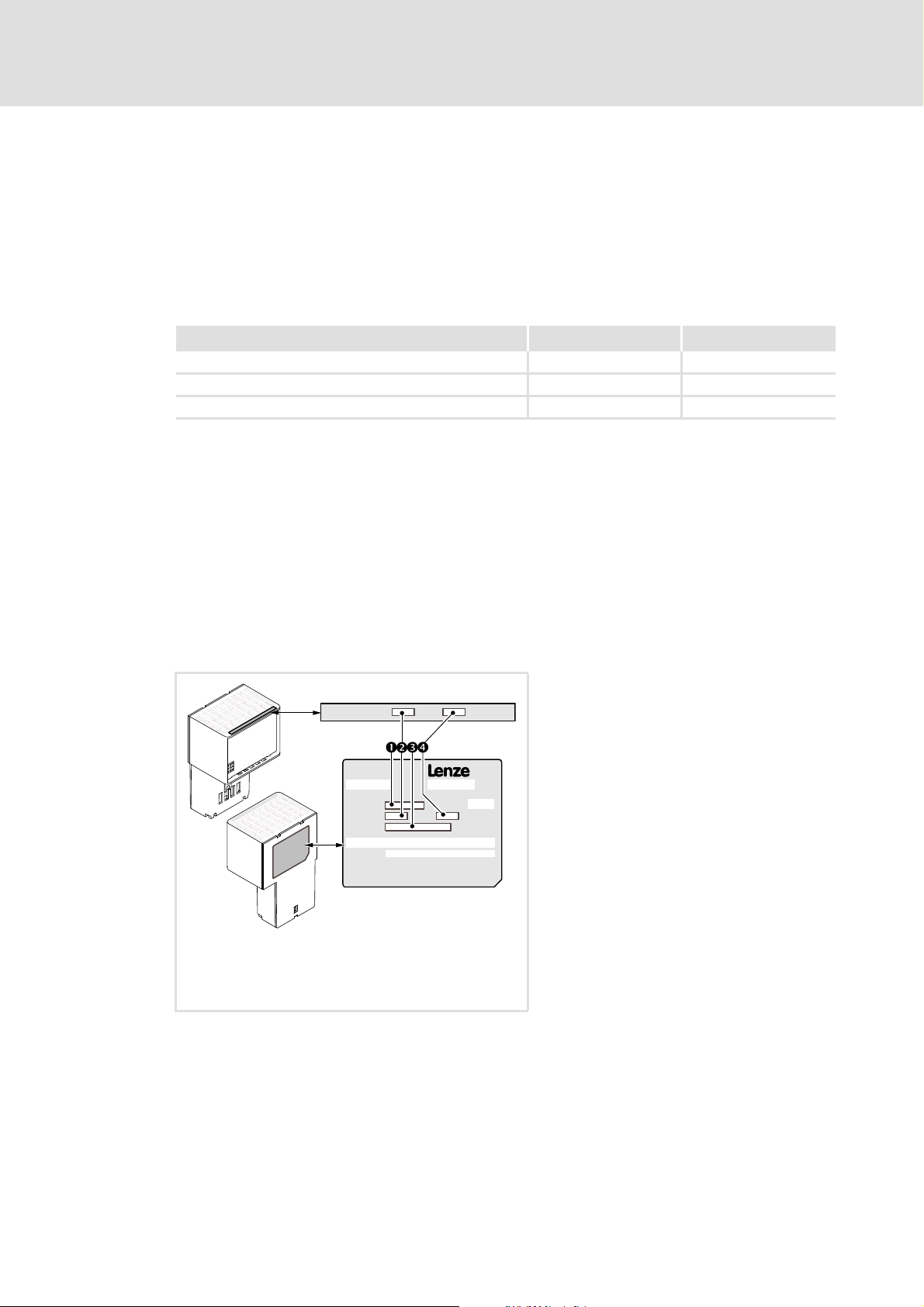
3.2 Identification
Type designation and hardware and software version of the communication module are
indicated on the nameplate:
[3-1] Identification data
E84YCEC004
1 Type designation (type)
E84 Product series
AVersion
Y Module identification: extension module
C Module type: communication module
EC Ethernet POWERLINK CN
V/S V: Coated version
S: Standard version
2 Hardware version (HW)
3 MAC address (MAC-ID)
00-0A-86-xx-yy-zz:
Hardware address of the communication
module for unique identification in the
network
4 Software version (SW)
EDS84AYCEC EN 3.0 - 09/2012 L 13
Page 14

E84AYCEC communication manual (Ethernet POWERLINK)
Product description
Features
3.3 Features
Interface module for the Ethernet POWERLINK communication system, for attachment
to the expansion slots of Inverter Drives 8400
The communication module can either be supplied internally by the standard device or
externally by a separate voltage source.
Real-time Ethernet with the Ethernet POWERLINK V2 communication profile for
motion and general applications
A line topology can be implemented by means of the integrated 2-port hub.
Supported functions:
– Ethernet POWERLINK CN
Use of max. 6 PDO crosslinks for the managing node or the controlled node to create
systems with "distributed intelligence"
Very short CN response times for optimal network performance
Parallel Ethernet communication between the Lenze »Engineer« and the Inverter Drive
8400 if an EPL router is used.
Access to all Lenze parameters
14 L EDS84AYCEC EN 3.0 - 09/2012
Page 15
E84AYCEC communication manual (Ethernet POWERLINK)
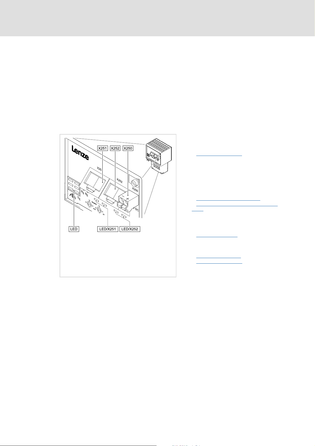
3.4 Connections and interfaces
2 RJ45 sockets for the Ethernet POWERLINK connection
2-pin plug connector for external voltage supply of the communication module.
2 rotary coding switches for setting the node address (node ID)
Front panel LEDs for diagnosing the ...
– voltage supply of the communication module;
– connection to the standard device;
– Ethernet POWERLINK connection;
– Ethernet POWERLINK activity.
Product description
Connections and interfaces
X250 External voltage supply of the communication
module
• 2-pin plug connector with spring connection
External voltage supply
( 35)
E84YCEC001D
[3-2] Communication module E84AYCEC (Ethernet POWERLINK)
X251 Ethernet POWERLINK port 1
X252 Ethernet POWERLINK port 2
• RJ45 sockets according to IEC/EN 60603-7
• each with 2 LED status displays for
diagnostics
Ethernet POWERLINK connection
Status displays at the RJ45 sockets (X251,
X252) ( 56)
x1
Rotary coding switch for setting the node
address (node ID)
x16
Node address setting
5 LED status displays for diagnostics
MS
Module status displays
ME
BS
Fieldbus status displays
BE
DE
( 38)
( 54)
( 55)
( 31)
EDS84AYCEC EN 3.0 - 09/2012 L 15
Page 16

E84AYCEC communication manual (Ethernet POWERLINK)
Technical data
General data and operating conditions
4 Technical data
4.1 General data and operating conditions
Field Values
Order designation E84AYCEC
Communication profile Ethernet POWERLINK
Communication medium S/FTP (screened foiled twisted pair, ISO/IEC 11801 or EN 50173), CAT 5e
Interface RJ45: Standard Ethernet (according to IEEE 802.3), 100Base-TX (Fast
Network topology Tree, star, and line
Node type Controlled node
Node addresses (node IDs) 1 … 239
Transmission mode Half duplex
Baud rate 100 Mbps
Voltage supply External supply via separate power supply unit
Conformities, approvals CE
Ethernet)
• "+": U = 24 V DC (20.4 V - 0 % ... 28.8 V + 0 %), I = 140 mA
• "-": Reference potential for external voltage supply
Hardware manual for Inverter Drives 8400
Here you can find the ambient conditions and data on the electromagnetic
compatibility (EMC), which also apply to the communication module.
16 L EDS84AYCEC EN 3.0 - 09/2012
Page 17

E84AYCEC communication manual (Ethernet POWERLINK)
4.2 Protective insulation
Danger!
Dangerous voltage
If the Inverter Drives 8400 are operated on a phase-earthed mains with a rated
mains voltage of 400 V, external measures need to be implemented in order to
ensure protection against accidental contact.
Possible consequences:
• Death or severe injury
Protective measures:
• If protection against accidental contact is required for the control terminals
of the controller and the connections of the plugged-in device modules, ...
– a double isolating distance must exist.
– the components to be connected must be provided with the second
isolating distance.
Technical data
Protective insulation
Note!
The existing protective insulation in the Inverter Drives 8400 is implemented
according to EN 61800-5-1.
EDS84AYCEC EN 3.0 - 09/2012 L 17
Page 18
E84AYCEC communication manual (Ethernet POWERLINK)
X4
X6
X5
X3
Bus
Ext. DC
MCI
X4
X6
X5
X3
X1X1
X105X105
X100X100
MMI
X106X106X106X106
X106X106X106X101
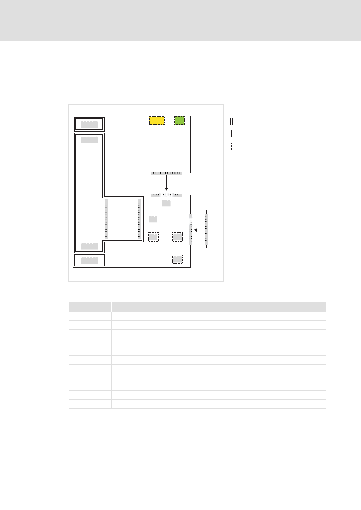
Technical data
Protective insulation
The following illustration ...
shows the arrangement of the terminal strips and the separate potential areas of the
Inverter Drive 8400.
serves to determine the decisive protective insulation between two terminals located
in differently insulated separate potential areas.
Reinforced insulation
Basic insulation
Functional insulation
[4-1] Protective insulation to EN61800-5-1
Terminal strip Connection
X100 Mains/DC-bus connection
X101 Relay contact
X105 Motor/brake resistor
X106 Motor PTC
X1 System bus (CANopen)
X3 Analog inputs/outputs
X4 Digital outputs
X5 Digital inputs
X6 Diagnostics
MCI Slot for the communication module
MMI Slot for the memory module
E84YCXX007
18 L EDS84AYCEC EN 3.0 - 09/2012
Page 19

E84AYCEC communication manual (Ethernet POWERLINK)
Technical data
Protective insulation
Example
Which type of protective insulation is used between the bus terminal of the device module
in slot MCI and the X100 mains terminal?
The separate potential area with the better protective insulation is decisive.
– The separate potential area of the bus terminal of the device module has a
"functional insulation".
– The separate potential area of the mains terminal has a "reinforced insulation".
Result: The insulation between the X100 mains terminal and the bus terminal is a
"reinforced insulation".
EDS84AYCEC EN 3.0 - 09/2012 L 19
Page 20

E84AYCEC communication manual (Ethernet POWERLINK)
Technical data
Ethernet POWERLINK communication data
4.3 Ethernet POWERLINK communication data
Field Values
Min. cycle time 400 s
Total cycle times 0.4 / 0.5 / 1.0 / 2.0 / 3.0 … 20.0 ms
Buffer size • Tx-iso: max. 1490 bytes
• Rx-iso: max. 1490 bytes
(max. 32 bytes of PDO user data)
Delay time • Controlled node (T
• Controlled node (T
Frame size Max. asynchronous frame size (MTU): 1518 bytes
SDO communication method UDP/IP or ASND
Number of RPDOs Max. 6 channels
RPDO user data per application (all
RPDOs)
Number of TPDOs 1 channel (data access of all nodes by broadcasting)
TPDO user data per application Max. 16 objects (32 bytes)
CN operating modes Support of ...
Max. 16 objects (max. 32 bytes)
•Multiplex CNs
•Optional CNs
Preq
SoA
- T
): approx. 2.6 s
Res
- T
): approx. 2.6 s
ASnd
Communication time
The communication time is the time between the start of a request and the arrival of the
corresponding response.
The communication times in the Ethernet POWERLINK network depend on ...
the processing time in the controller;
the telegram runtime (baud rate / telegram length);
the nesting depth of the network.
Processing time in the controller
Data Processing time
Process data approx. 2 ms
+ 0 ... 1 ms
+ 1 ... x ms
Parameter data approx. 30 ms + 20 ms tolerance (typical)
• For some codes, the processing time may be longer (see software
manual/»Engineer« online help for the Inverter Drive 8400).
Update cycle
Processing time in the module
Runtime of the application task of the technology
application used (tolerance)
There are no interdependencies between parameter data and process data.
20 L EDS84AYCEC EN 3.0 - 09/2012
Page 21
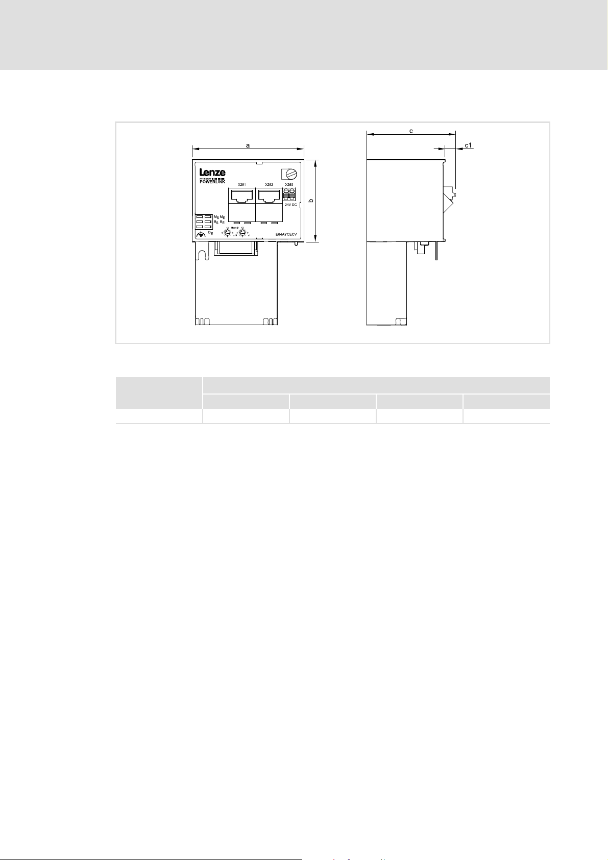
4.4 Dimensions
E84AYCEC communication manual (Ethernet POWERLINK)
Technical data
Dimensions
[4-2] Dimensions
E84AYCEC 67 50 57 8
E84YCER001B
Type Dimensions [mm]
a b c c1
EDS84AYCEC EN 3.0 - 09/2012 L 21
Page 22

E84AYCEC communication manual (Ethernet POWERLINK)
Installation
5 Installation
Stop!
Electrostatic discharge
Electronic components within the communication module can be damaged or
destroyed by electrostatic discharge.
Possible consequences:
• The communication module is defective.
• Fieldbus communication is not possible or faulty.
Protective measures
• Free yourself from any electrostatic charge before you touch the module.
22 L EDS84AYCEC EN 3.0 - 09/2012
Page 23
E84AYCEC communication manual (Ethernet POWERLINK)
5.1 Mechanical installation
The communication module can be plugged in or unplugged from the MCI slot when the
controller is switched on. When the module is plugged in, it is detected automatically, and
a function and version plausibility check is executed.
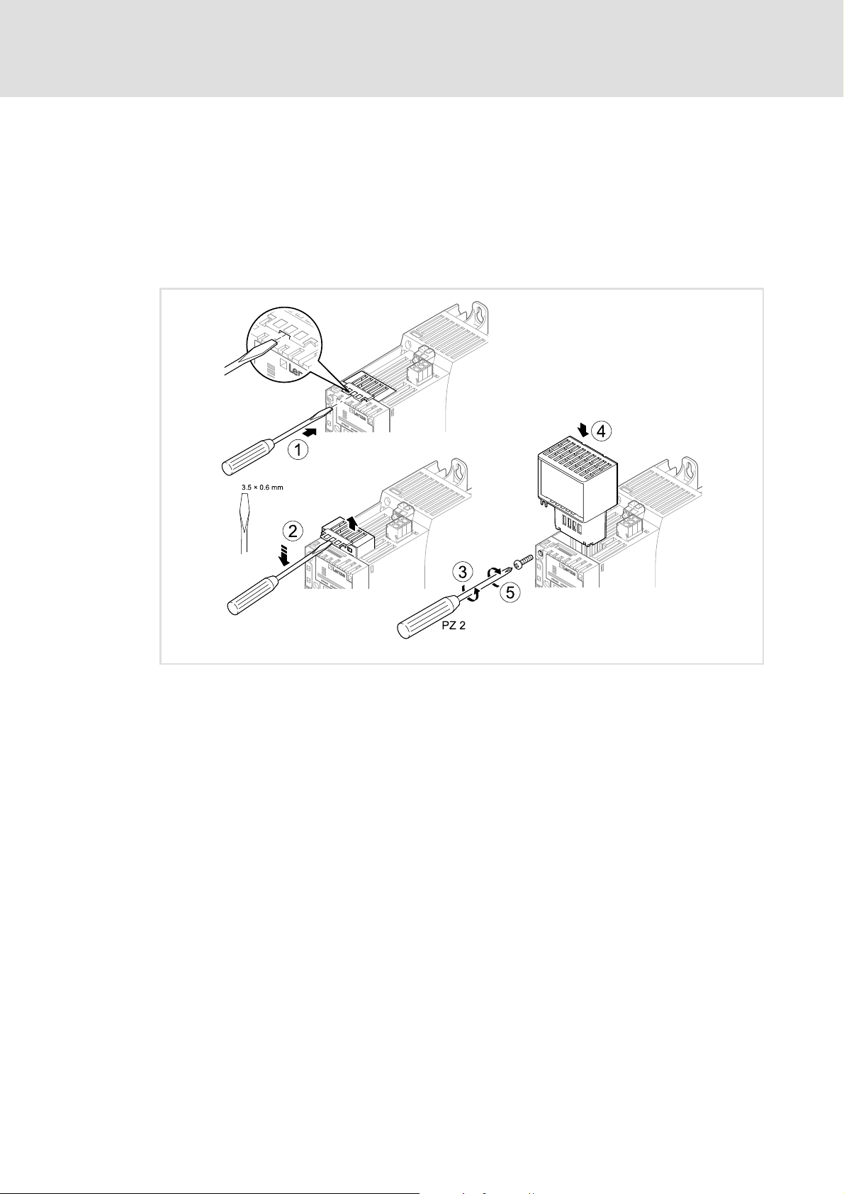
5.1.1 Mounting for standard devices of 0.25 kW and 0.37 kW
Installation
Mechanical installation
[5-1] Mounting for standard devices of 0.25 kW and 0.37 kW
Mounting steps
1. Use a screwdriver to lever out the cover of the MCI slot of the standard device and
remove it (1, 2).
2. Loosen the securing screw for the communication module at the standard device (3).
3. Insert the communication module into the MCI slot of the standard device (4).
4. Tighten the securing screw again (5).
E84YCPM002D
EDS84AYCEC EN 3.0 - 09/2012 L 23
Page 24
E84AYCEC communication manual (Ethernet POWERLINK)
Installation
Mechanical installation
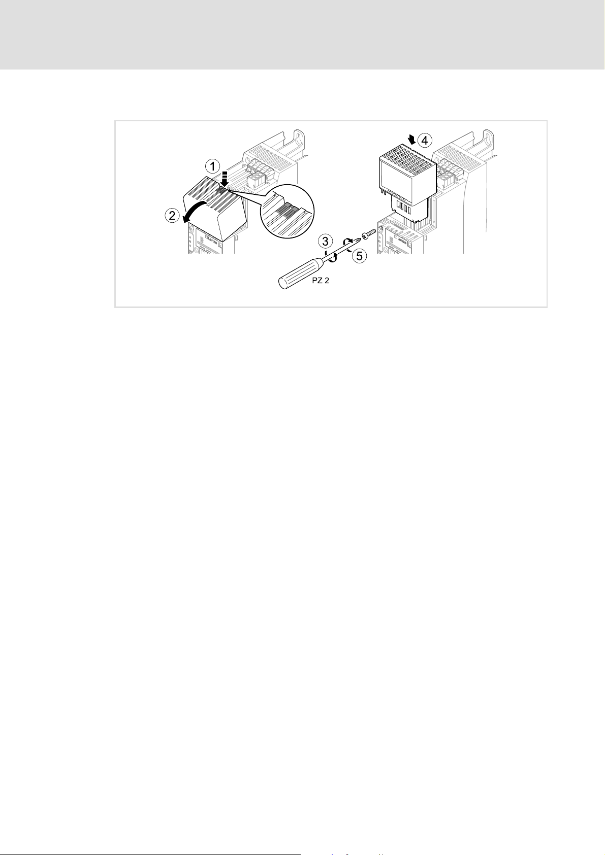
5.1.2 Mounting for standard devices of 0.55 kW or more
[5-2] Mounting for standard devices of 0.55 kW or more
E84YCPM002A
Mounting steps
1. Slightly press on the marked spot on the top of the MCI slot cover of the standard
device (1).
2. Tilt the cover forward and remove it from the standard device (2).
3. Loosen the securing screw for the communication module at the standard device (3).
4. Insert the communication module into the MCI slot of the standard device (4).
5. Tighten the securing screw again (5).
24 L EDS84AYCEC EN 3.0 - 09/2012
Page 25
E84AYCEC communication manual (Ethernet POWERLINK)
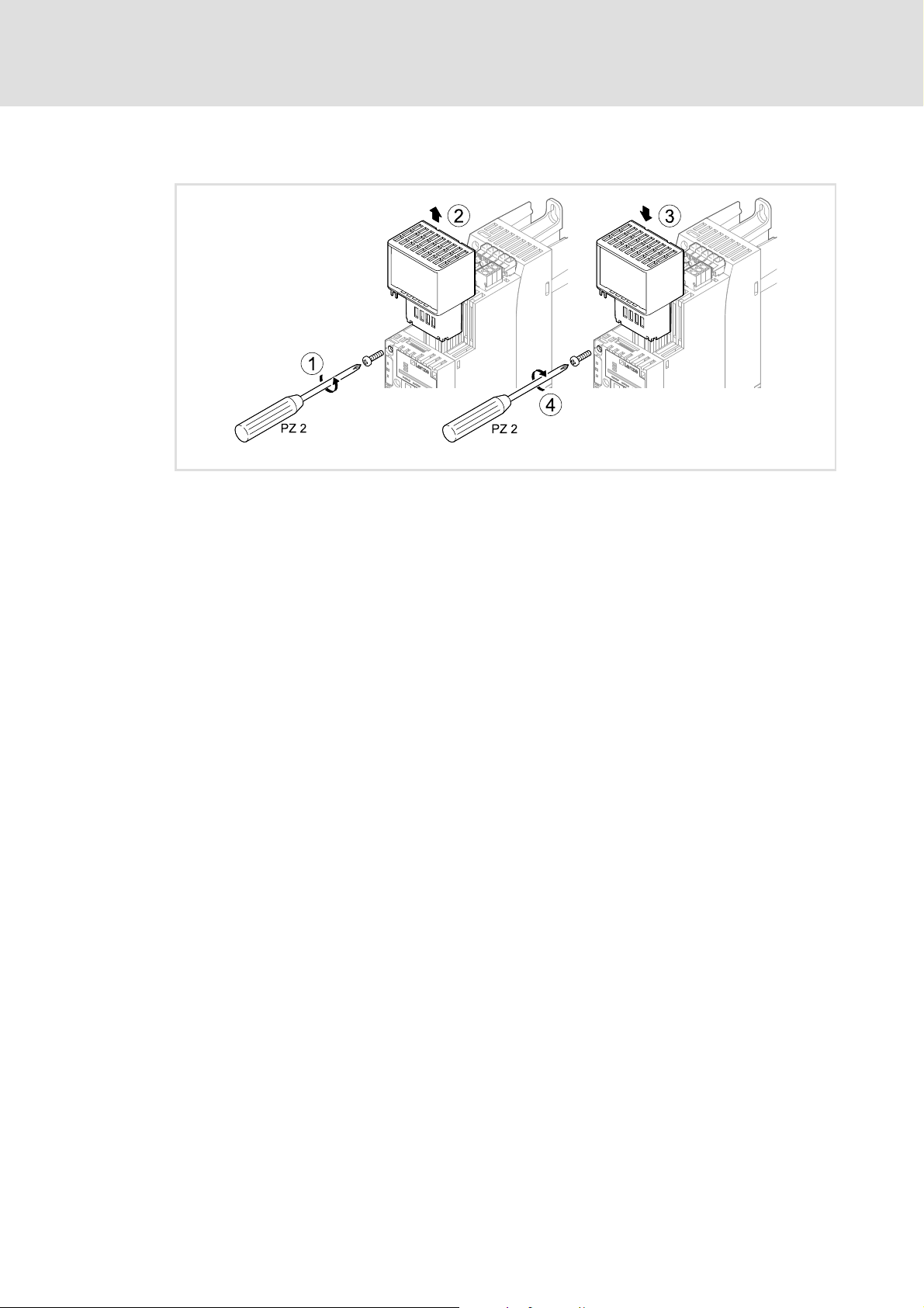
5.1.3 Exchanging the communication module
[5-3] Exchanging the communication module
Installation
Mechanical installation
E84YCPM002B
Mounting steps
1. Loosen the securing screw for the communication module at the standard device (1).
2. Pull the communication module out of the MCI slot of the standard device (2).
3. Insert the new communication module into the MCI slot of the standard device (3).
4. Tighten the securing screw again (4).
EDS84AYCEC EN 3.0 - 09/2012 L 25
Page 26

E84AYCEC communication manual (Ethernet POWERLINK)
Installation
Electrical installation
5.2 Electrical installation
Documentation for the standard device, control system, system/machine
Observe the notes and wiring instructions provided therein.
5.2.1 Wiring according to EMC guidelines
In typical systems a standard shielding of the Ethernet cable is sufficient.
In environments with very strong interferences, the EMC compatibility can be improved by
an additional earthing of the cable shield on both sides.
Observe the following notes:
1. Remove the plastic sheath of the cable at a length of 2 cm.
2. Fasten the cable shield to the shield support of the standard device.
26 L EDS84AYCEC EN 3.0 - 09/2012
Page 27
E84AYCEC communication manual (Ethernet POWERLINK)
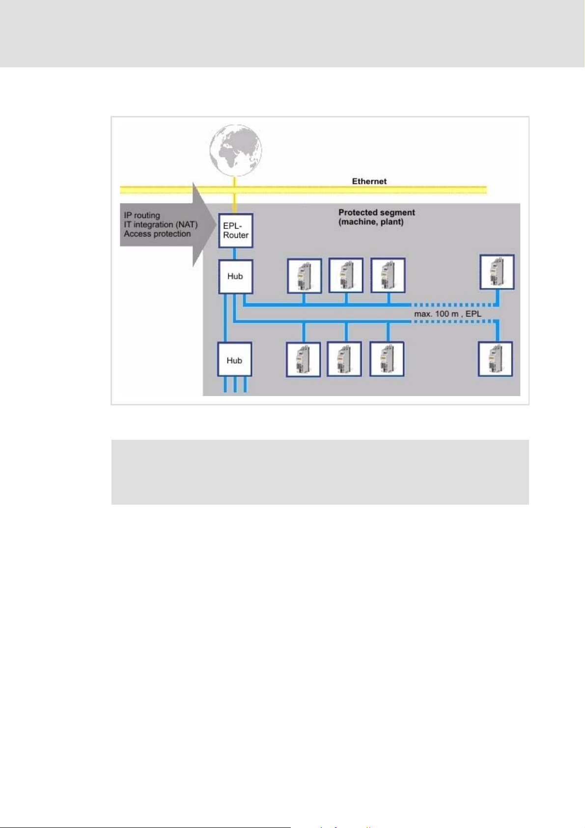
5.2.2 Network topology
Installation
Electrical installation
[5-4] Network topology for Ethernet POWERLINK
Note!
The use of class I hubs and switches inside the EPL network segment is not
permitted.
Inside the segment only Ethernet hubs may be used as infrastructure elements. The hubs
must meet the requirements on class II repeaters acc. to IEEE 802.3u.
For this purpose Lenze offers the dual hub integrated into the communication module and
the separate eight-fold hub, type E94AZCEH.
Class I hubs and switches are not permissible since they have considerably longer delay
times for the frame forwarding and a bigger jitter. Both sizes reduce the real-time
capability and dynamics.
The cable length between both nodes is limited to 100 m.
The topology rules (IEEE 802.3u) required for controlling the collisions may be violated in
the EPL network segment since according to the EPL access order frame collisions are
prevented. This enables a structure of lines and any hybrid forms between star and line
topology.
EDS84AYCEC EN 3.0 - 09/2012 L 27
Page 28

E84AYCEC communication manual (Ethernet POWERLINK)
1. CN group
2. CN group
Managing
Node
Hub
Installation
Electrical installation
Recommended topology
For an easy configuration and due to many possible topology variants we recommend to
create networks according to the following rules:
1. Create CN groups with up to 10 nodes.
2. Connect CN groups in star shape to the managing node.
3. Connect CN groups to the managing node via one external hub each.
– For more than 2 CN groups, use an external 8-port hub (e.g. Lenze hub E94AZCEH).
– For max. 7 CN groups one hub is sufficient.
– For more than 7 CN groups, use further hubs.
– The groups can be distributed on the hubs just as you like.
– Observe the restrictions of the used managing node.
Note!
E94AYCEP communication module als Managing Node
With maximally 2 CN groups and the use of an E94AYCEP communication
module as Managing Node, connect the CN group(s) directly to the Ethernet
POWERLINK terminals X211 and X212 of the E94AYCEP communication module.
[5-5] Star topology for 1 to 2 CN groups
E94YCEP033
28 L EDS84AYCEC EN 3.0 - 09/2012
Page 29

E84AYCEC communication manual (Ethernet POWERLINK)
5.2.3 Ethernet POWERLINK
Note!
Standard Ethernet nodes are not permitted in the Ethernet POWERLINK network
segment.
In order to use the real-time capability of the Ethernet POWERLINK technology, Ethernet
POWERLINK nodes must be interconnected in a separate network segment.
In accordance with the EPL rules, only the managing node controls the network access of
EPL nodes. The managing node is the only node that transmits autonomously. The slave
nodes (i.e. all controlled nodes) only transmit when they are entitled to transmit by the
managing node.
Non-EPL nodes (e.g. PCs) typically violate these rules by sending frames independently of
the managing node. These frames interfere with the cyclic frame exchange of the EPL
nodes and impede the real-time capability of Ethernet POWERLINK.
Installation
Electrical installation
Connection to the standard Ethernet network
The connection to an external standard Ethernet network is carried out via an Ethernet
POWERLINK router or an Ethernet POWERLINK gateway.
These infrastructure components separate the network traffic in the Ethernet POWERLINK
network segment from the one in the standard Ethernet. The handling of the frames
depend on their direction:
Standard Ethernet ---> EPL network segment:
Only frames that are addressed to nodes in the EPL network segment are forwarded.
The forwarding takes place in the asynchronous area of the EPL cycle.
EPL network segment ---> standard Ethernet:
Only asynchronous frames that are not addressed to nodes in the EPL network segment
are forwarded.
Tip!
Detailed information on the function and setting of the router or gateway can be
found in the documentation of the component manufacturer.
EDS84AYCEC EN 3.0 - 09/2012 L 29
Page 30

E84AYCEC communication manual (Ethernet POWERLINK)
Installation
Electrical installation
5.2.4 Basic Ethernet Mode
Note!
Operation in the "Basic Ethernet Mode" does not permit any real-time
communication.
The communication module can be operated in the "Basic Ethernet Mode" for a basic
parameter setting provided that the following applies:
1. Operation of the module with network address 239.
– IP address: 192.168.100.[EPL address]
– see Node address setting
2. No operation with real-time EPL must be carried out.
3. No integration of a managing node (EPL address 240) into the standard Ethernet
network.
( 38)
30 L EDS84AYCEC EN 3.0 - 09/2012
Page 31

E84AYCEC communication manual (Ethernet POWERLINK)
5.2.5 Ethernet POWERLINK connection
Ethernet POWERLINK is connected via the RJ45 sockets X251 (P1) and X252 (P2).
Installation
Electrical installation
[5-6] Ethernet POWERLINK connections X251 (P1) and X252 (P2)
If possible, do not wire more than 10 nodes in a row in a network line.
In case of more than 10 nodes you should deactivate the automatic calculation of the
hub level in the »Engineer« and enter it manually to increase the performance.
With a cycle time of 1 ms, 25 nodes can be operated.
– The number of nodes can be increased if the EPL cycle time is increased as well.
You can use a standard Ethernet patch cable to connect the communication module to
the Ethernet POWERLINK fieldbus (see Ethernet cable specification
The installation and removal of the Ethernet cables is optimised for use of connectors
according to the "Automation Initiative of German Domestic Automobile
Manufacturers" (AIDA).
Note!
To prevent the RJ45 socket from being damaged, hold the Ethernet cable
connector straight (at a right angle) when inserting it into or removing it from
the socket.
E84YCEC001E
( 33)).
EDS84AYCEC EN 3.0 - 09/2012 L 31
Page 32

E84AYCEC communication manual (Ethernet POWERLINK)
Installation
Electrical installation
Pin assignment of the RJ45 sockets
RJ45 socket Pin Signal
1Tx +
2Tx -
3Rx +
4-
5-
6Rx -
E94AYCXX004C
7-
8-
Tip!
The Ethernet POWERLINK interfaces feature an auto MDIX function. This function
adjusts the polarity of the RJ45 interfaces so that a connection is established
irrespective of the polarity of the opposite Ethernet POWERLINK interface, and
irrespective of the type of cable used (standard patch cable or crossover cable).
32 L EDS84AYCEC EN 3.0 - 09/2012
Page 33

E84AYCEC communication manual (Ethernet POWERLINK)
5.2.6 Ethernet cable specification
Note!
Only use cables that meet the listed specifications.
Ethernet cable specification
Ethernet standard Standard Ethernet (in accordance with IEEE 802.3), 100Base-TX (Fast
Cable type S/FTP (screened foiled twisted pair, ISO/IEC 11801 or EN 50173), CAT 5e
Damping 23.2 dB (at 100 MHz and per 100 m)
Crosstalk damping 24 dB (at 100 MHz and 100 m each)
Return loss 10 dB (100 m each)
Surge impedance 100
Installation
Electrical installation
Ethernet)
Structure of the Ethernet cable
[5-7] Structure of the Ethernet cable (S/FTP, CAT 5e)
E94YCEP016
A Cable insulation
B Braid
C Foil shield
TP1
Twisted core pairs 1 ... 4
...
Colour code of the Ethernet cable
TP4
( 34)
EDS84AYCEC EN 3.0 - 09/2012 L 33
Page 34

E84AYCEC communication manual (Ethernet POWERLINK)
Installation
Electrical installation
Colour code of the Ethernet cable
Note!
The wiring and colour codes are standardised in EIA/TIA 568A/568B.
4-pin Ethernet cables according to industry standard are permissible. This cable
type only connects the assigned pins 1, 2, 3 and 6.
[5-8] Ethernet connector in accordance with EIA/TIA 568A/568B
Pair Pin Signal EIA/TIA 568A EIA/TIA 568B
3 1 Tx + White/green White/orange
2 Tx - Green Orange
2 3 Rx + White/orange White/green
1 4 Blue Blue
5 White/blue Blue/white
2 6 Rx - Orange Green
47 White/brown White/brown
8Brown Brown
E94YCEI004A
34 L EDS84AYCEC EN 3.0 - 09/2012
Page 35

E84AYCEC communication manual (Ethernet POWERLINK)
5.2.7 External voltage supply
The communication module can be externally supplied with voltage via separate supply
cables at the 2-pin plug connector X250.
Note!
Always use a separate power supply unit safely separated according to
EN 61800-5-1 ("SELV/PELV") in every control cabinet for external voltage supply.
External voltage supply of the communication module is required if the
communication via the bus should be maintained when the supply of the standard
device fails.
The parameters of a standard device separated from the mains cannot be accessed.
Wiring of the X250 plug connector
Installation
Electrical installation
Stop!
Only wire the plug connector if the standard device is disconnected from the
mains.
[5-9] Wiring of the 2-pin plug connector with spring connection
How to wire the plug connector with spring connection:
1. Press a screwdriver into the notch below the terminal and keep it pressed.
E84AYCXX010
2. Place the supply cable in the terminal.
3. Remove the screwdriver from the notch.
EDS84AYCEC EN 3.0 - 09/2012 L 35
Page 36

E84AYCEC communication manual (Ethernet POWERLINK)
Installation
Electrical installation
Assignment of the X250 plug connector
Designation Description
+ U = 24 V DC (20.4 V - 0 % ... 28.8 V + 0 %)
I = 140 mA
- Reference potential for external voltage supply
Terminal data
Field Values
Electrical connection 2-pin plug connector with spring connection
Possible connections rigid:
0.2 ... 1.5 mm
flexible:
without wire end ferrule
0.2 ... 1.5 mm
with wire end ferrule, without plastic sleeve
0.2 ... 1.5 mm
with wire end ferrule, with plastic sleeve
0.2 ... 1.5 mm
2
(AWG 24 ... 16)
2
(AWG 24 ... 16)
2
(AWG 24 ... 16)
2
(AWG 24 ... 16)
Bare end 10 mm
36 L EDS84AYCEC EN 3.0 - 09/2012
Page 37

E84AYCEC communication manual (Ethernet POWERLINK)
6 Commissioning
During commissioning, system-related data such as motor parameters, operating
parameters, responses, and parameters for fieldbus communication are defined in the
controller. For Lenze devices, this is done by means of codes.
The codes of the controller and of the communication are stored as a non-volatile data set
in the memory module.
In addition, other codes are available for diagnosing and monitoring the nodes.
Commissioning
Before initial switch-on
Parameter reference
6.1 Before initial switch-on
Stop!
Before switching on the Inverter Drive 8400 and the communication module for
the first time, check the entire wiring for completeness, short circuit and earth
fault.
( 66)
EDS84AYCEC EN 3.0 - 09/2012 L 37
Page 38

E84AYCEC communication manual (Ethernet POWERLINK)
Commissioning
Node address setting
6.2 Node address setting
Note!
• Each network node address must only be used once.
• The node address setting in the configuration software (e.g. »Engineer«) and
the rotary encoder switches must be identical for each node.
• Adjustable address range: 1 ... 239
• Switch the voltage supply of the communication module off and on again to
activate changed settings.
The node address is set via the two front panel rotary coding switches "Node ID".
[6-1] Rotary coding switches "Node ID"
The labelling of the rotary coding switches corresponds to the values for determining
the node address.
Valid addresses for the communication module in the EPL network:
– 1 … 100: Controlled node with Lenze module E94AYCEP as managing node
– 1 … 239: Controlled node with managing node of another manufacturer
The corresponding Ethernet IP address of the communication module results from the
address setting of the rotary coding switches:
– IP address: 192.168.100.[EPL address]
Symbol_NodeID
38 L EDS84AYCEC EN 3.0 - 09/2012
Page 39

E84AYCEC communication manual (Ethernet POWERLINK)
Possible settings of the rotary coding switches
Position of the rotary coding switches Resulting node address
Commissioning
Node address setting
0
0 ... 14 1 ... 15 1 ... 239
15 0 ... 15 239
× 16
0
Value from code C13899
× 1
[6-2] Internal check of the rotary coding switch setting after the system start
Example: Setting of the node address "52"
Position of the rotary coding switches Resulting node address
3 × 16 4 × 1(3 × 16) + (4 × 1) = 52
EDS84AYCEC EN 3.0 - 09/2012 L 39
Page 40

E84AYCEC communication manual (Ethernet POWERLINK)
Commissioning
Setting and displays in the »Engineer«
6.3 Setting and displays in the »Engineer«
The IP address (C13000
Settings tab.
) and the MAC address (C13004) are displayed on the
40 L EDS84AYCEC EN 3.0 - 09/2012
Page 41

6.4 Initial switch-on
Documentation for the standard device
Observe the safety instructions and information on residual hazards contained
in this documentation.
Note!
Establishing communication
When the communication module is externally supplied, the standard device
must also be switched on to establish communication.
After communication has been established, communication of the externally
supplied module is independent of the switching status of the standard device.
E84AYCEC communication manual (Ethernet POWERLINK)
Commissioning
Initial switch-on
Activating changed setting
In order to activate any changed settings, ...
• execute the device command "11: Save all parameter sets" via the standard
device code C00002 and ...
• then execute a "reset node" of the node or switch off and then on again the
voltage supply of the communication module.
Protection against uncontrolled restart
Following a fault (short-term mains failure, for example), it is sometimes
undesirable or even impermissible for the drive to restart.
The restart protection is activated in the Lenze setting of the Inverter Drives
8400.
You can set the restart behaviour of the controller via C00142 ("Autostart
Option"):
• C00142 = 9 (Lenze setting)
– The controller remains inhibited (even if the fault is no longer active).
– Bit 0 (inhibit when device On) and bit 3 (inhibit in case of undervoltage) are
set.
– The drive restarts in a controlled mode through explicit controller enable:
LOW-HIGH edge at digital input X4/RFR.
• C00142 = 8 (Enabled)
– In order to enable the device directly when switching it on, bit 0 must be set
to zero (FALSE).
– An uncontrolled restart of the drive is possible.
EDS84AYCEC EN 3.0 - 09/2012 L 41
Page 42
E84AYCEC communication manual (Ethernet POWERLINK)
Commissioning
Initial switch-on
Initial switch-on and diagnosing
1. Switch on the controller and check whether it is ready for operation using the
diagnostic LEDs of the communication module.
• Red diagnostic LEDs must not be on.
• The following signalling should be visible:
LED Colour Status Meaning
MS Green On Module Status Module status displays
DE - Off Device Error
X251 Green On LED is lit if a connection to the node has been established.
X252 Green On
2. If not already done, load the EPL configuration into the controller.
3. Repeat steps 1 and 2 for all EPL nodes.
4. Start network.
Status displays at the RJ45 sockets (X251, X252)
( 54)
( 56)
The network starts automatically if you set the managing node last.
Otherwise there are two options:
• Switch off the network nodes and switch them on together or
• execute a fault reset on the managing node (EPL address 240).
5. Check the EPL network again using the diagnostic LEDs of the communication
module.
The following signalling should be visible:
LED Colour Status Meaning
MS Green On Module Status Module status displays
ME - Off Module Error
BE - Off Bus Error
DE - Off Device Error
BS Green On Bus Status Fieldbus status displays
X251 Green On LED is lit if a connection to the node has been established.
X252 Green On
Status displays at the RJ45 sockets (X251, X252)
( 54)
( 55)
( 56)
42 L EDS84AYCEC EN 3.0 - 09/2012
Page 43

E84AYCEC communication manual (Ethernet POWERLINK)
6.5 Drive synchronisation
Examples of the use of drive synchronisation via Ethernet POWERLINK:
Implementation of the "electrical shaft"
Specification of cyclic position information
Exactly simultaneous data processing of several drives
Optimisation of the processing times of cyclic process data (PDO).
Settings in the »Engineer«
Commissioning
Drive synchronisation
Set "MCI" as synchronisation source in code C01120 of the controller.
The cycle time setpoint C01121 and the phase position C01122 are automatically
calculated from the communication module. Default settings of these parameters are
ignored.
It is not necessary to adjust the sync window C01123 and the sync correction width
C01124.
Software manual/»Engineer« online help for the Inverter Drive 8400
Here you can find detailed information on drive synchronisation and the
corresponding parameters.
EDS84AYCEC EN 3.0 - 09/2012 L 43
Page 44

E84AYCEC communication manual (Ethernet POWERLINK)
Commissioning
Optimisation of networks
6.6 Optimisation of networks
SDO bandwidth
Note!
The channel bandwidth should only be increased if the network is below
capacity limit.
The SDO channel width (C13075
parameter setting and diagnostics. A higher value improves the transmission of large
amounts of data (e.g. parameter downloads) and at the same time reduces the number of
possible nodes.
Maximum time for device search
During the device search, the managing node has to wait until all controlled nodes have
been found.
Unless all controlled nodes are available in the defined EPL cycle time, the
"EPL_BOOTUP_1" error message is generated. The managing node remains in this
status.
If the managing node has found all controlled nodes, it starts the network.
Due to machine or system-specific switch-on sequences, it may be required to adapt the
following EPL objects:
CN object 0x1F99: NMT_CNBasicEthernetTimeout_U32 (C13078
MN object 0x1F89: NMT_BootTime_REC
) is the size of the asynchronous channel used for
)
Note!
In order to avoid a too quick change to the "Basic Ethernet Mode" ( 30), the value
of the 0x1F99 object (NMT_CNBasicEthernetTimeout_U32) must be higher than
the value of the 0x1F89 object (NMT_BootTime_REC) which is the case by
default.
Index table
( 83)
44 L EDS84AYCEC EN 3.0 - 09/2012
Page 45

E84AYCEC communication manual (Ethernet POWERLINK)
7 Process data transfer
Ethernet POWERLINK transmits process data, parameter data, configuration data and
diagnostic data between the managing node and the controlled nodes. Depending on their
time-critical behaviour, the data are transmitted via different communication channels.
Process data are transmitted via the process data channel.
Process data serve to control the Inverter Drive 8400.
The transfer of process data is time-critical.
Process data are cyclically transferred between the managing node and the controlled
nodes (permanent exchange of current input and output data).
The managing node can directly access the process data. In the PLC, for instance, the
data are directly assigned to the I/O area.
Up to 16 process data words (16 bit/word) can be exchanged per direction.
Process data are not saved on the controller.
Process data transfer
Process data are, for instance, setpoints, actual values, control and status words.
EDS84AYCEC EN 3.0 - 09/2012 L 45
Page 46

E84AYCEC communication manual (Ethernet POWERLINK)
/3B0FL,Q
"
E&WUOB%
E&WUOB%
Z&WUO
E,QB%
E,QB%
Z,Q
Z,Q
GQ,QBS
/3B0FL2XW
E6WDWHB%
E6WDWHB%
Z6WDWH
E2XWB%
E2XWB%
Z2XW
Z2XW
GQ2XWBS
"
)LHOGEXV
$SSOLFDWLRQ
)%LQWHUFRQQHFWLRQ
&RPPXQLFDWLRQPRGXOH
0&,LQWHUIDFH
Process data transfer
Access to process data / PDO mapping
7.1 Access to process data / PDO mapping
Process data (MCI-PDOs) are transferred via the MCI interface.
A maximum of 16 words are exchanged per direction.
The process data are accessed via the port blocks LP_MciIn and LP_MciOut. These port
blocks are also referred to as process data channels.
The port block LP_MciIn maps the received MCI-PDOs.
The port block LP_MciOut maps the MCI-PDOs to be sent.
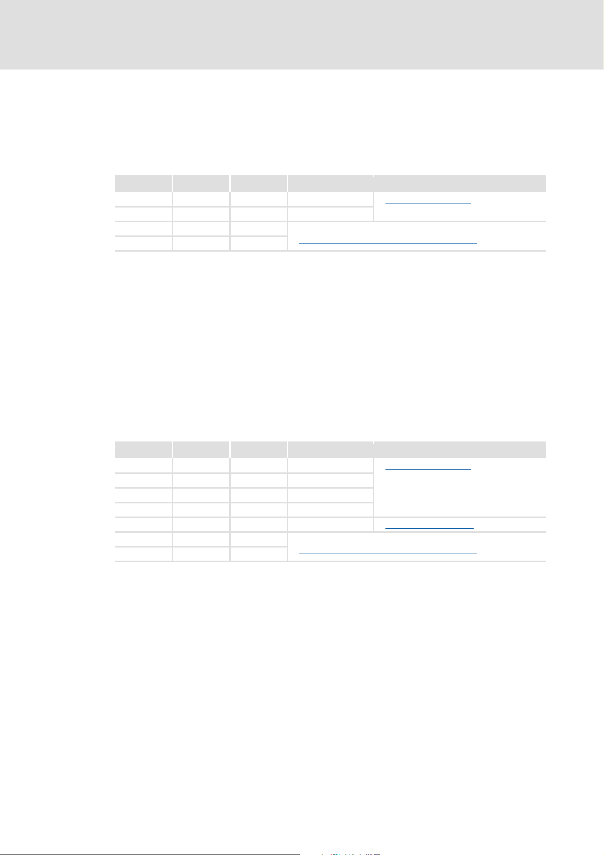
The port/function block interconnection for the process data objects (PDO) is carried
out with the Lenze »Engineer«.
[7-1] Outer and inner data transfer between bus system, controller and application
Software manual / »Engineer« online help for the Inverter Drive 8400
Here you can find detailed information on the port/function block
interconnection in the »Engineer« and on the port blocks.
46 L EDS84AYCEC EN 3.0 - 09/2012
Page 47
E84AYCEC communication manual (Ethernet POWERLINK)
Preconfigured port interconnection of the process data objects (PDO)
Note!
The »Engineer« screenshots shown on the following pages are only examples of
the setting sequence and the resulting displays.
The data in the display fields may differ from the ones of your project.
7.2 Preconfigured port interconnection of the process data objects (PDO)
The preconfigured port interconnection of the process data objects can be activated by
setting the standard device code C00007 = "40: MCI".
The function block editor (FB Editor) can be used to display the port blocks LP_MciIn and
LP_MciOut with the preconfigured interconnections:
Process data transfer
EDS84AYCEC EN 3.0 - 09/2012 L 47
Page 48

E84AYCEC communication manual (Ethernet POWERLINK)
Process data transfer
Freely configured port interconnection of the process data objects (PDO)
7.3 Freely configured port interconnection of the process data objects (PDO)
How to configure the port interconnection freely in the »Engineer«:
1. Go to the project view of the »Engineer« and select the application (A).
2. Select the port blocks MCI_IN or MCI_OUT on the Ports tab with a mouse-click and
activate them with the Activate button (B).
3. Click the Change Variable ... button.
48 L EDS84AYCEC EN 3.0 - 09/2012
Page 49

E84AYCEC communication manual (Ethernet POWERLINK)
Process data transfer
Freely configured port interconnection of the process data objects (PDO)
4. The button serves to assign signals to the process data words in the Signal
Assignment--> Function Block dialog box.
Select signals and confirm the selection by clicking the OK button.
EDS84AYCEC EN 3.0 - 09/2012 L 49
Page 50

E84AYCEC communication manual (Ethernet POWERLINK)
Process data transfer
Freely configured port interconnection of the process data objects (PDO)
Furthermore you can assign signals to the individual control and status bits of the
WORD_1 ... WORD_4 process data words via the and buttons.
Select signals and confirm the selection by clicking the OK button.
50 L EDS84AYCEC EN 3.0 - 09/2012
Page 51

E84AYCEC communication manual (Ethernet POWERLINK)
Process data transfer
Freely configured port interconnection of the process data objects (PDO)
Tip!
When the port blocks LP_MciIn and LP_MciOut are activated (see 1.), they will be
visible in the FB Editor. Here you can also assign signals to the process data words.
In order to improve the clarity, unassigned signals can be hidden for each block.
EDS84AYCEC EN 3.0 - 09/2012 L 51
Page 52

E84AYCEC communication manual (Ethernet POWERLINK)
Monitoring
8 Monitoring
Interruption of Ethernet POWERLINK communication
An interruption of Ethernet POWERLINK communication in the OPERATIONAL state, e.g. by
cable break or failure of the managing node, is detected by the controlled node. The
response to this interruption of communication depends on the following settings:
1. The watchdog monitoring time defined in the managing node is transferred to the
controlled node when the Ethernet POWERLINK communication is initialised.
If the controlled node being in the OPERATIONAL state does not receive valid process
data, the process data are handled according to the setting in C13885
sent by the managing node can either be used or set to zero.)
If communication fails, the controlled node state changes to PRE-OPERATIONAL (see
C13861
By default, there is no response in the controlled node
2. To cause a response by the controlled node, you additionally have to ...
– set a response of the controlled node (C13880/1
) and the red LED "BE" is activated (see Fieldbus status displays ( 55)).
.
).
. (The last data
52 L EDS84AYCEC EN 3.0 - 09/2012
Page 53

E84AYCEC communication manual (Ethernet POWERLINK)
9 Diagnostics
The LEDs on the front panel of the communication module serve to diagnose faults.
9.1 LED status displays
Note!
LED status displays for error-free operation:
•The LEDs MS
• The green LED at the RJ45 sockets X251 and X252 is permanently lit or
blinking
The following status displays are distinguished:
Diagnostics
LED status displays
( 54) and BS ( 55) are permanently lit.
( 56).
Module status displays
Fieldbus status displays ( 55)
Status displays at the RJ45 sockets (X251, X252) ( 56)
( 54)
EDS84AYCEC EN 3.0 - 09/2012 L 53
Page 54
E84AYCEC communication manual (Ethernet POWERLINK)
200 ms
200 ms
Diagnostics
LED status displays
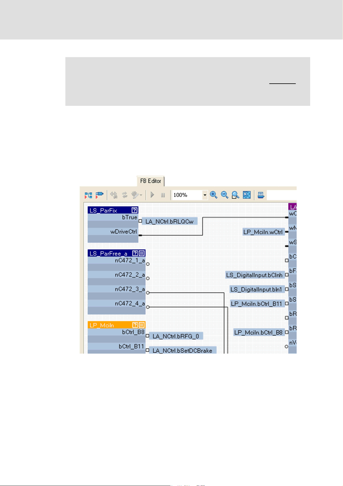
9.1.1 Module status displays
The LEDs MS, ME, BE and DE indicate the module status.
MS Module Status
ME Module Error
BE Bus Error
DE Device Error
E84YCEC003A
LED Colour Status Description
MS Green On
The communication module is supplied with voltage and has
established a connection to the standard device.
Blinking
The communication module is supplied with voltage, but has not
established a connection to the standard device. (Standard device is
switched off, initialising or not present.)
ME Red On
An error concerning the communication module has occurred.
BE Red On
A fieldbus error has occurred.
DE Red On
The communication module is not accepted by the standard device.
See notes given in the documentation for the standard device.
54 L EDS84AYCEC EN 3.0 - 09/2012
Page 55
E84AYCEC communication manual (Ethernet POWERLINK)
1 s
1 s
1 s
50ms
200 ms
200 ms
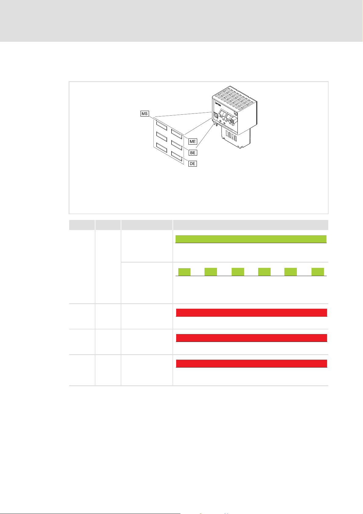
9.1.2 Fieldbus status displays
The BS LED indicates the fieldbus status.
BS Bus Status
Diagnostics
LED status displays
E84YCEC003B
LED Colour Status Description
BS Green Off The communication module is not active on the fieldbus or is in the
INIT state.
Blinking
EPL network is in the initialisation phase.
EPL status: NMT_CS_PREOPERATIONAL_1
Blinking
EPL network is in the initialisation phase with cyclic traffic.
EPL status: NMT_CS_PREOPERATIONAL_2
Blinking
EPL node is waiting for the start signal.
EPL status: NMT_CS_READY_TO_OPERATE
Blinking
The EPL node has not found a managing node and is in Basic Et hernet
Mode ( 30).
EPL status: NMT_CS_BASIC_ETHERNET
Blinking
EPL node is in the "Stopped" status (waiting for disconnection).
EPL status: NMT_CS_STOPPED
On
EPL node is in the operating phase.
EPL status: NMT_CS_OPERATIONAL
EDS84AYCEC EN 3.0 - 09/2012 L 55
Page 56
E84AYCEC communication manual (Ethernet POWERLINK)
50ms
Diagnostics
LED status displays
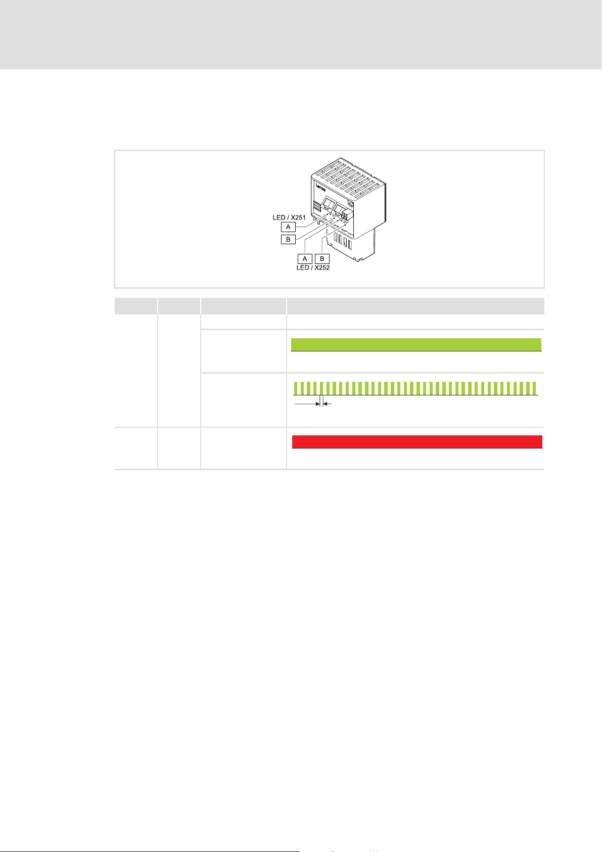
9.1.3 Status displays at the RJ45 sockets (X251, X252)
The LEDs at the RJ45 sockets X251 and X252 indicate the Ethernet POWERLINK connection
status.
LED Colour Status Description
A Green Off No Ethernet POWERLINK connection
On
E84YCER005
Flickers
BRed On
Ethernet POWERLINK connection has been established.
Data communication of Ethernet POWERLINK connection is active.
Ethernet POWERLINK collision has occurred.
56 L EDS84AYCEC EN 3.0 - 09/2012
Page 57

E84AYCEC communication manual (Ethernet POWERLINK)
1. Diagnostics - standard device / EPL module
Standard
device
switched
on?
Module or standard
device defect.
Please exchange.
Module or standard
device defect.
Please exchange.
Module does not
match the standard
device, maybe due
to a version conflict.
Use a suitable
combination.
Switch standard
device on and off
again.
Go back to point 1.
Switch on standard
device.
Go back to point 1.
Go back to point 1.
Go back to point 1.
Switch standard
device on and off
again.
Standard
device
switched
on?
MS
signal?
Module
plugged in
correctly?
Switch on standard
device.
Point 2
DE is lit?
Error still
existent?
yes
no
yes
blinking
no
off
on
no
yes
no
yes
yes
no
9.2 Troubleshooting with module signalling
In the following, troubleshooting via the module signals will be described.
Please particularly observe ...
the basic readiness for operation between the standard device and the communication
module;
the network wiring.
Diagnostics
Troubleshooting with module signalling
[9-1] Diagnostics - standard device / Ethernet POWERLINK module
EDS84AYCEC EN 3.0 - 09/2012 L 57
E94YCEP051
Page 58

E84AYCEC communication manual (Ethernet POWERLINK)
2. Diagnostics - network wiring
X251/252
green LED
blinking?
Check the cable
connection and the
cable.
Check EPL master,
see point 1.
Switch on the EPL
devices.
Go back to point 2.
Create EPL wiring.
Go back to point 1.
Is at least one
cable
plugged?
X251/252,
green LED on?
Is the
module
connected to
it switched
on?
Point 3
Check EPL
master.
BS on /
blinking?
yes
no
no
on
yes
no
yes
no
yes
off
Check EPL wiring to
EPL master.
Diagnostics
Troubleshooting with module signalling
[9-2] Diagnostics - network wiring
Note!
The BS (Bus State) LED refers to the Lenze communication module E94AYCEP as
managing node.
This status display applies analogously to the managing nodes of other
manufacturers.
E94YCEP052
58 L EDS84AYCEC EN 3.0 - 09/2012
Page 59

E84AYCEC communication manual (Ethernet POWERLINK)
3. Diagnostics - EPL operation
Make further error
search with the
Engineer.
Go back to point 3.
Standard device: Make a
fault reset.
Then wait 30 s.
EPL master:
ME on?
Make a fault reset
at the standard
Device.
End
Wait 30 s.
EPL master: BS
on / blinking?
yes
no
yes
on
blinking / off
no
End
on
Make further error
search with the
Engineer.
Wait 30 s.
EPL master: BS
on / blinking?
EPL master:
ME on?
BE on?
blinking / off
Diagnostics
Troubleshooting with module signalling
[9-3] Diagnostics - Ethernet POWERLINK operation
Note!
The LEDs ME (Module Error), BE (Bus Error) and BS (Bus State) refer to the Lenze
communication module E94AYCEP as managing node.
These status displays apply analogously to the managing nodes of other
manufacturers.
E94YCEP053
EDS84AYCEC EN 3.0 - 09/2012 L 59
Page 60

E84AYCEC communication manual (Ethernet POWERLINK)
Diagnostics
Diagnostic data
9.3 Diagnostic data
Pending diagnostic data are signalled from the controlled node to the managing node
by means of an emergency message.
Code C13887
serves to suppress sending emergency messages to the managing node.
You can select which type of error is to be suppressed.
Errors and warnings in the Inverter Drive 8400 and the plugged communication
module are sent to the managing node as extended diagnostic messages.
The diagnostic data are visible via the PLC Engineering software.
Bytes Meaning Value [hex]
1 ... 6 Diagnostic block header 0x0010 001C 0100
7 ... 8 Alarm type 0x0001 (Diagnosis)
9 ... 12 API (Application Programming Interface) 0x0000 0000
13, 14 Slot number 0x0001 / 0x0002
15, 16 Subslot number 0x0001
17 ... 20 Module ID ID corresponding to module
21 ... 24 Submodule number ID corresponding to module
25, 26 Alarm specification 0xB000
27, 28 User structure ID 0x0001
29 ... 32 Error code
60 L EDS84AYCEC EN 3.0 - 09/2012
Page 61
E84AYCEC communication manual (Ethernet POWERLINK)
Byte 32 Byte 31 Byte 30 Byte 29
Bit
162526
31
015
29
30
Bit
31
30
00
26
29
XXX0
Bit
Bit
16
25
000
111111
0
0
15
000 1
11
00000000
11
Bit
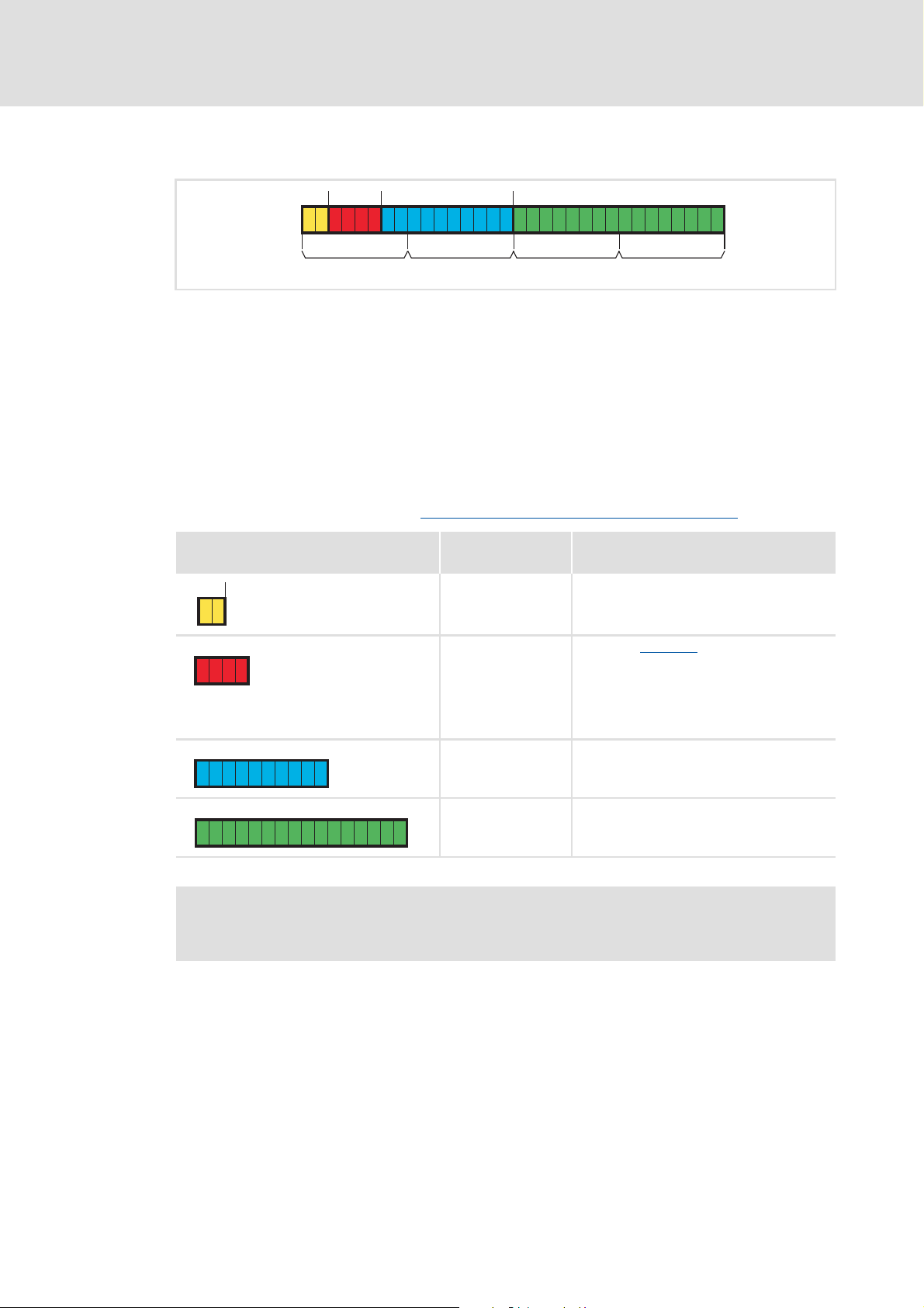
Error code of Inverter Drive 8400
[9-4] Error code of Inverter Drive 8400
The error code of the Inverter Drive 8400 can be found in bytes 29 ... 32 of the
diagnostic message.
In the logbook and in code C00165 of the standard device, the error number is shown
in the following syntax in order to facilitate the readability:
[Error type].[Error subject area no.].[Error ID]
Example
Diagnostics
Diagnostic data
Diagnostic message of the error "EPL: State OPERATIONAL lost [0x01bc8131]
Bit assignment
(Bytes 29 ... 32)
Information Values from the example
Reserved 0
Error type / error
response
Error subject area 0x01bc (444
Error ID 0x8131 (33073
Setting via C13880/1
• 0: No error response
•1: Error
•3: Quick stop
• 4: Warning locked
•6: Information
)
dec
)
dec
:
Software manual/»Engineer« online help for Inverter Drive 8400
Here you can find detailed information on error codes.
":
EDS84AYCEC EN 3.0 - 09/2012 L 61
Page 62

E84AYCEC communication manual (Ethernet POWERLINK)
Error messages
Short overview of the Ethernet POWERLINK error messages
10 Error messages
This chapter supplements the error list in the software manual and the »Engineer« online
help for the Inverter Drive 8400 by the error messages of the communication module.
Software manual/»Engineer« online help for the Inverter Drive 8400
Here you will find general information on diagnostics & fault analysis and error
messages.
10.1 Short overview of the Ethernet POWERLINK error messages
The following table contains all error messages of the communication module in
numerical order of the error numbers. Moreover the preset error response and - if
applicable - the parameters for setting the error response are specified.
Tip!
When you click the cross-reference in the first column, you will get to the detailed
description (causes and remedies) of the corresponding error message.
Error no.
[hex]
0x01bc3100 444 12544 EPL: Lost connection to 8400 target 1: Error -
0x01bc5531
0x01bc5532
0x01bc5533
0x01bc6010
0x01bc6011
0x01bc6100
0x01bc6101
0x01bc6110
0x01bc641f
0x01bc6420
0x01bc6430
0x01bc8131
0x01bc8261 444 33377 EPL: Invalid address selected 1: Error -
0x01bc8265
0x01bc8266 444 33382 EPL: Frame error (CRC) 0: None C13880/3
Subject area
no.
[dec]
444 21809 EPL: NV memory: No access 1: Error -
444 21810 EPL: NV memory: Read error 1: Error -
444 21811 EPL: NV memory: Write error 1: Error -
444 24592 EPL: Restart after watchdog reset 1: Error -
444 24593 EPL: Watchdog reset 1: Error -
444 24832 EPL: Software error 1: Error -
444 24833 EPL: Fatal software error 1: Error -
444 24848 EPL: Invalid PDO mapping 1: Error -
444 25631 EPL: Invalid parameter set 1: Error -
444 25632 EPL: Default setting loaded 1: Error -
444 25648 EPL: Invalid module configuration 1: Error -
444 33073 EPL: OPERATIONAL status left 1: Error C13880/1
444 33381 EPL: Synchronisation of MN lost 0: None C13880/2
Error no.
[dec]
Error text Error type
(Error response)
adjustable in
62 L EDS84AYCEC EN 3.0 - 09/2012
Page 63

E84AYCEC communication manual (Ethernet POWERLINK)
10.2 Possible causes and remedies
This chapter contains all error messages of the communication module in numerical order
of the error number. Possible causes and remedies as well as responses to the error
messages are described in detail.
Error messages
Possible causes and remedies
Short overview of the Ethernet POWERLINK error messages
EPL: Lost connection to 8400 target [0x01bc3100]
Response (Lenze setting in bold) Setting: not possible
None System fault Fault Trouble Quick stop by trouble Warning locked Warning Information
Cause Remedy
MCI communication to Inverter Drive 8400 is
interrupted.
• Inverter Drive 8400 is switched off.
• The communication module is not connected
correctly at the MCI slot of the Inverter Drive 8400.
EPL: NV Memory: No access [0x01bc5531]
Response (Lenze setting in bold) Setting: not possible
None System fault Fault Trouble Quick stop by trouble Warning locked Warning Information
Cause Remedy
Access via standard device to the parameter set in the
memory module failed.
EPL: NV Memory: Read error [0x01bc5532]
( 62)
• Switch on Inverter Drive 8400.
• Check screwed connection of the communication
module at the MCI slot of the Inverter Drive 8400.
• Send the communication module and Inverter Drive
8400 together with a description of the fault to Lenze.
Redownload the application (incl. module).
Response (Lenze setting in bold) Setting: not possible
None System fault Fault Trouble Quick stop by trouble Warning locked Warning Information
Cause Remedy
Parameter in the memory module could not be read. Redownload the application (incl. module).
EPL: NV Memory: Write error [0x01bc5533]
Response (Lenze setting in bold) Setting: not possible
None System fault Fault Trouble Quick stop by trouble Warning locked Warning Information
Cause Remedy
Parameter in the memory module could not be written. Redownload the application (incl. module).
EPL: Restart after watchdog reset [0x01bc6010]
Response (Lenze setting in bold) Setting: not possible
None System fault Fault Trouble Quick stop by trouble Warning locked Warning Information
Cause Remedy
Communication module is defective. Send the communication module and a description of
the fault to Lenze.
EDS84AYCEC EN 3.0 - 09/2012 L 63
Page 64

E84AYCEC communication manual (Ethernet POWERLINK)
Error messages
Possible causes and remedies
EPL: Watchdog reset [0x01bc6011]
Response (Lenze setting in bold) Setting: not possible
None System fault Fault Trouble Quick stop by trouble Warning locked Warning Information
Cause Remedy
Communication module is defective. Send the communication module and a description of
EPL: Software error [0x01bc6100]
Response (Lenze setting in bold) Setting: not possible
None System fault Fault Trouble Quick stop by trouble Warning locked Warning Information
Cause Remedy
Communication module is defective. Send the communication module and a description of
EPL: Fatal software error [0x01bc6101]
the fault to Lenze.
the fault to Lenze.
Response (Lenze setting in bold) Setting: not possible
None System fault Fault Trouble Quick stop by trouble Warning locked Warning Information
Cause Remedy
Communication module is defective. Send the communication module and a description of
EPL: PDO Mapping invalid [0x01bc6110]
Response (Lenze setting in bold) Setting: not possible
None System fault Fault Trouble Quick stop by trouble Warning locked warning Information
Cause Remedy
Invalid mapping configuration. Correct the mapping configuration.
EPL: Invalid parameter set [0x01bc641f]
Response (Lenze setting in bold) Setting: not possible
None System fault Fault Trouble Quick stop by trouble Warning locked warning Information
Cause Remedy
Loading of an active parameter set was not possible. Redownload the application (incl. module).
EPL: Factory settings loaded [0x01bc6420]
the fault to Lenze.
Response (Lenze setting in bold) Setting: not possible
None System fault Fault Trouble Quick stop by trouble Warning locked warning Information
Cause Remedy
Access via standard device to the parameter set in the
Redownload the application (incl. module).
memory module failed.
64 L EDS84AYCEC EN 3.0 - 09/2012
Page 65

E84AYCEC communication manual (Ethernet POWERLINK)
EPL: Invalid module configuration [0x01bc6430]
Response (Lenze setting in bold) Setting: not possible
None System fault Fault Trouble Quick stop by trouble Warning locked Warning Information
Cause Remedy
Module configuration is faulty. Check the module configuration and correct it.
EPL: State OPERATIONAL lost [0x01bc8131]
Response (Lenze setting in bold) Setting: C13880/1
None System fault Fault Trouble Quick stop by trouble Warning locked Warning Information
Cause Remedy
Data exchange via Ethernet POWERLINK has been
terminated.
• See also chapter "Interruption of Ethernet
POWERLINK communication" ( 52).
Error messages
Possible causes and remedies
• Check the network cable (plug) and replace it if
necessary.
• Connect the network cable to the Ethernet
POWERLINK terminals X251 or X252 and continue to
check the status of the managing node.
EPL: Invalid address selected [0x01bc8261]
Response (Lenze setting in bold) Setting: not possible
None System fault Fault Trouble Quick stop by trouble Warning locked Warning Information
Cause Remedy
An invalid IP address has been assigned by the managing
node via Ethernet POWERLINK or set as node ID.
EPL: Synchronisation lost from MN [0x01bc8265]
Response (Lenze setting in bold) Setting: C13880/2
None System fault Fault Trouble Quick stop by trouble Warning locked Warning Information
Cause Remedy
In the controlled node, the synchronisation cycle of the
managing node has failed. The controlled node changes
automatically to the NMT_CS_PREOPERATIONAL_1
state and waits for a new run-up by the managing node.
EPL: Telegram error detected (CRC) [0x01bc8266]
Response (Lenze setting in bold) Setting: C13880/3
None System fault Fault Trouble Quick stop by trouble Warning locked Warning Information
• Ensure that a valid IP address is assigned by the
managing node via Ethernet POWERLINK.
• Set valid node ID.
Node address setting
( 38)
• Check network cable and components (failure of
managing node, router).
• Restart managing node if required.
Cause Remedy
Faulty Ethernet frames (CRC error) have been detected.
Possible causes:
• A device in the network is not EPL-compliant.
• EMC interference is too strong.
EDS84AYCEC EN 3.0 - 09/2012 L 65
• Check if a non-EPL-compliant device is in the network
(e.g. diagnostics PC).
• Reduce EMC interference on the network or use an
additional shield connection.
Page 66

E84AYCEC communication manual (Ethernet POWERLINK)
Parameter reference
Parameters of the communication module
11 Parameter reference
This chapter supplements the parameter list and the table of attributes for the Inverter
Drive 8400 contained in the software manual and in the »Engineer« online help by the
parameters of the communication module E84AYCEC (Ethernet POWERLINK).
Software manual/»Engineer« online help for Inverter Drive 8400
Here you will find general information on parameters.
11.1 Parameters of the communication module
This chapter lists the parameters of the E84AYCEC communication module (Ethernet
POWERLINK) in numerically ascending order.
C13000
C13001
Parameter | Name:
C13000 | 0x1E40.2 IP Address
The code displays the IP address of the communication module.
• The IP address is derived from the EPL node address (Node ID): 192.168.100.[Node ID]
• The node ID is derived from the coding switch position or from C13899
Node address setting
Display range (min. value | unit | max. value)
0.0.0.0
(0x00000000)
Subcodes Info
C13000/1 IP address
Read access Write access CINH PLC-STOP No transfer PDO_MAP_RX PDO_MAP_TX COM MOT
Parameter | Name:
C13001 | 0x1E40.3 Subnet Mask
The code declares the IP subnet mask which restricts the directly addressable IP address range (i.e. without a
gateway in the EPL segment of the routers). The value 255.255.255.0 (0xFFFFFF00) is always assigned to the subnet
mask in one segment.
Display range (min. value | unit | max. value)
255.0.0.0
(0xFF000000)
Subcodes Info
C13001/1 EPL IP Subnet Mask
Read access Write access CINH PLC-STOP No transfer PDO_MAP_RX PDO_MAP_TX COM MOT
( 38)
255.255.255.255
(0xFFFFFFFF)
• Lenze setting: 0xC0A86401 = 192.168.100.1
255.255.255.0
(0xFFFFFF00)
• Lenze setting: 0xFFFFFF00 = 255.255.255.0
.
Data type: UNSIGNED_32
Index: 11575
Data type: UNSIGNED_32
Index: 11574
= 2D37
d
= 2D36
d
h
h
66 L EDS84AYCEC EN 3.0 - 09/2012
Page 67

C13003
E84AYCEC communication manual (Ethernet POWERLINK)
Parameter reference
Parameters of the communication module
C13004
Parameter | Name:
C13003 | 0x1E40.5 IP Address Router
Data type: UNSIGNED_32
Index: 11572
= 2D34
d
The code declares the IP address of the router which connects the EPL segment to the higher-level network. The
standard entry corresponds to the standard router address of the EPL specification:
192.168.100.254
Permissible entries replace the lowest-order byte of the standard entry with the EPL address of the node which has
the function of a router.
Setting range (min. value | unit | max. value)
0.0.0.0
(0x00000000)
255.255.255.255
(0xFFFFFFFF)
Subcodes Lenze setting Info
C13003/1 3232261374 IP address router
• Lenze setting: 0xC0A864FE = 192.168.100.254
Read access Write access CINH PLC-STOP No transfer PDO_MAP_RX PDO_MAP_TX COM MOT
Parameter | Name:
C13004 | 0x1030.5 MAC Address
Data type: OCTET_STRING
Index: 11571
= 2D33
d
The code indicates the physical address (MAC address) of the Ethernet interface of the communication module.
When the communication module is produced, the MAC address is assigned unequivocally worldwide and provides
addressing on the lowest level.
Subcodes Info
C13004/1 MAC Address (octet string[6])
00-0A-86-xx-yy-zz
• 00-0A-86 = Lenze
• xx-yy-zz = consecutive number
Read access Write access CINH PLC-STOP No transfer PDO_MAP_RX PDO_MAP_TX COM MOT
h
h
EDS84AYCEC EN 3.0 - 09/2012 L 67
Page 68

E84AYCEC communication manual (Ethernet POWERLINK)
Parameter reference
Parameters of the communication module
C13028
Parameter | Name:
C13028 | 0x1F81 Node Assignment CN
Data type: UNSIGNED_32
Index: 11547
The code declares the controlled nodes 1 ... 100 and their properties.
Value is bit-coded:
Bit 0 ... 31 see below
Subcodes Lenze setting Info
C13028/1 0
... ..
C13028/100 0
Read access Write access CINH PLC-STOP No transfer PDO_MAP_RX PDO_MAP_TX COM MOT
The describing bit field has the following structure:
Bit Value Description
0 (LSB) 0 EPL node with this ID does not exist.
1 EPL node with this ID exists.
1 0 EPL node with this ID is not a controlled node.
1 EPL node with this ID is a controlled node.
2 0 On detection of a booting controlled node, the application will not be informed.
1 On detection of a booting controlled node, the application will be informed and the
3 0 Optional controlled node
1 Obligatory controlled node
4 0 The managing node is allowed to send reset commands.
1 The managing node must not send any reset command.
5 0 Software version verification of the controlled node is not required.
1 Software version verification of the controlled node is required.
6 0 Automatic application software update is not allowed.
1 Automatic application software update is allowed.
7- Reserved / No function
8 0 Isochronously accessed controlled node
1 Asynchronously accessed controlled node (bit 9 is irrelevant)
9 0 Continuously accessed controlled node
1 Multiplex EPL nodes are supported.
10 0 No "Ethernet POWERLINK to standard Ethernet" router function.
1 Device can be used as an "Ethernet POWERLINK to standard Ethernet" router (router type 1).
11 0 No "Ethernet POWERLINK to fieldbus" router function.
1 The device can be used as an "Ethernet POWERLINK to fieldbus" router (router type 1).
12 0 The managing node does not send any PRes frames
1 The managing node sends PRes frames
13 ... 30 - Reserved / No function
31 (MSB) 0 Bits 0 ... 30 inhibited
1 Bits 0 ... 30 enabled
controlled node will be started.
= 2D1B
d
h
68 L EDS84AYCEC EN 3.0 - 09/2012
Page 69

C13029
E84AYCEC communication manual (Ethernet POWERLINK)
Parameter reference
Parameters of the communication module
Parameter | Name:
C13029 | 0x1F81 Node Assignment
Data type: UNSIGNED_32
Index: 11546
The code declares managing node, diagnostic device, and router, and describes their properties.
Value is bit-coded:
Bit 0 ... 31 see below
Subcodes Lenze setting Info
C13029/1 2147483661 EPL node assignment managing node
Lenze setting (hex): 0x8000000D
C13029/2 0 EPL node assignment diagnostic device
Lenze setting (hex): 0x00000000
C13029/3 2147483655 EPL node assignment router
Lenze setting (hex): 0x80000007
Read access Write access CINH PLC-STOP No transfer PDO_MAP_RX PDO_MAP_TX COM MOT
The describing bit field has the following structure:
Bit Value Description
0 (LSB) 0 EPL node with this ID does not exist.
1 EPL node with this ID exists.
1 0 EPL node with this ID is not a controlled node.
1 EPL node with this ID is a controlled node.
2 0 On detection of a booting controlled node, the application will not be informed.
1 On detection of a booting controlled node, the application will be informed and the
3 0 Optional controlled node
1 Obligatory controlled node
4 0 The managing node is allowed to send reset commands.
1 The managing node must not send any reset command.
5 0 Software version verification of the controlled node is not required.
1 Software version verification of the controlled node is required.
6 0 Automatic application software update is not allowed.
1 Automatic application software update is allowed.
7- Reserved / No function
8 0 Isochronously accessed controlled node
1 Asynchronously accessed controlled node (bit 9 is irrelevant)
9 0 Continuously accessed controlled node
1 Multiplex EPL nodes are supported.
10 0 No "Ethernet POWERLINK to standard Ethernet" router function.
1 The device can be used as an "Ethernet POWERLINK to standard Ethernet" router (router
11 0 No "Ethernet POWERLINK to fieldbus" router function.
1 The device can be used as an "Ethernet POWERLINK to fieldbus" router (router type 1).
12 0 The managing node does not send any PRes frames
1 The managing node sends PRes frames
13 ... 30 - Reserved / No function
31 (MSB) 0 Bits 0 ... 30 inhibited
1 Bits 0 ... 30 enabled
controlled node will be started.
type 1).
= 2D1A
d
h
EDS84AYCEC EN 3.0 - 09/2012 L 69
Page 70

E84AYCEC communication manual (Ethernet POWERLINK)
Parameter reference
Parameters of the communication module
C13040
Parameter | Name:
C13040 | 0x1F82 Feature Flags
The code displays the Ethernet POWERLINK features implemented by the EPL node.
Lenze standard value: 0x00000207
Value is bit-coded:
Bit 0 ... 31 see below
Read access Write access CINH PLC-STOP No transfer PDO_MAP_RX PDO_MAP_TX COM MOT
The describing bit field has the following structure:
Bit Value Description
0 (LSB) 0 Asynchronous access
1 Isochronous access
1 0 No SDO by UDP/IP
1 SDO by UDP/IP
2 0 No SDO by EPL "ASnd"
1 SDO by EPL "ASnd"
3 0 No SDO integrated in PDO
1 SDO integrated in PDO
4 0 No "NMT Info Services"
1 "NMT Info Services" supported
5 0 No extended "NMT State Commands"
1 Extended "NMT State Commands" supported
6 0 No dynamic PDO mapping
1 Dynamic PDO mapping supported
7- Reserved / No function
8 0 No configuration manager function
1 Configuration manager function
9 0 Only isochronous cyclic access permitted.
1 Isochronous multiplexed access possible.
10 0 No address assignment via software
1 Address assignment via software
11 - Reserved / No function
12 0 No "Ethernet POWERLINK to standard Ethernet" router function.
1 The device can be used as an "Ethernet POWERLINK to standard Ethernet" router (router
13 0 No "Ethernet POWERLINK to fieldbus" router function.
1 The device can be used as an "Ethernet POWERLINK to fieldbus" router (router type 1).
14 ... 31
- Reserved / No function
(MSB)
type 1).
Data type: UNSIGNED_32
Index: 11535
= 2D0F
d
h
70 L EDS84AYCEC EN 3.0 - 09/2012
Page 71

C13060
E84AYCEC communication manual (Ethernet POWERLINK)
Parameter reference
Parameters of the communication module
Parameter | Name:
C13060 | 0x1006 Cycle Time
Data type: UNSIGNED_32
Index: 11515
= 2CFB
d
The code defines the length of the EPL cycle in μs.
• In the configured state, this code must have an identical value in all EPL nodes.
• The selected value must correspond to the actual bus cycle time so that the internal monitoring functions work
correctly.
Selection list (Lenze setting printed in bold)
400 400
500 500
600 600
800 800
1000 1000
2000 2000
3000 3000
4000 4000
5000 5000
6000 6000
7000 7000
8000 8000
9000 9000
10000 10000
11000 11000
12000 12000
13000 13000
14000 14000
15000 15000
16000 16000
17000 17000
18000 18000
19000 19000
20000 20000
Read access Write access CINH PLC-STOP No transfer PDO_MAP_RX PDO_MAP_TX COM MOT
h
EDS84AYCEC EN 3.0 - 09/2012 L 71
Page 72

E84AYCEC communication manual (Ethernet POWERLINK)
Parameter reference
Parameters of the communication module
C13066
C13067
Parameter | Name:
C13066 | 0x1F8D PResPayloadLimit RPDO CN
Data type: UNSIGNED_16
Index: 11509
= 2CF5
d
The code defines the reserved user data length of the PRes telegrams for controlled nodes 1 ... 100. Each subcode
number corresponds to one EPL node with the same node ID. The EPL node must be enabled via code C13028
.
The subcodes describe the PRes telegrams received. The value must be within the range of 36 ... 1490 bytes.
The values are upper limit values for the entire size of the PDO mappings for received PRes telegrams.
In the configured state, the values stored for the EPL nodes must be identical to the corresponding C13072
entries.
C13066 must have an identical value in all EPL nodes of the network.
Setting range (min. value | unit | max. value)
0 byte 1490
Subcodes Lenze setting Info
C13066/1 0 byte
... ...
C13066/100 0 byte
Read access Write access CINH PLC-STOP No transfer PDO_MAP_RX PDO_MAP_TX COM MOT
Parameter | Name:
C13067 | 0x1F8D PResPayloadLimit RPDO
Data type: UNSIGNED_16
Index: 11508
= 2CF4
d
The code defines the reserved user data length of the PRes frames for managing node, diagnostic device or router.
Each subcode number corresponds to one EPL node with the same node ID. The EPL node must be enabled via code
.
C13028
The subcode describes the PRes telegrams received. The value must be within the limits of 36 ... 1490 bytes.
The values are upper limit values for the entire size of the PDO mappings for received PRes telegrams.
In the configured state, the values stored for the nodes must be identical to the corresponding C13072
entries.
C13067 must have an identical value in all EPL nodes of the network.
Setting range (min. value | unit | max. value)
0 byte 1490
Subcodes Lenze setting Info
C13067/1 0 byte Managing node
C13067/2 0 byte Diagnostics device
C13067/3 0 byte Router
Read access Write access CINH PLC-STOP No transfer PDO_MAP_RX PDO_MAP_TX COM MOT
h
h
C13071
Parameter | Name:
C13071 | 0x1F98.4 PReqPayloadLimit RPDO
Data type: UNSIGNED_16
Index: 11504
= 2CF0
d
The code defines the maximum data size to be received by the controlled node via PReq for the current network
configuration. C13071 is an upper limit value for the entire size of the PDO mapping for the PReq telegram.
In the configured state, the value must be identical to the entry for a response valid for the EPL node.
Setting range (min. value | unit | max. value) Lenze setting
36 byte 1490 36 bytes
Read access Write access CINH PLC-STOP No transfer PDO_MAP_RX PDO_MAP_TX COM MOT
72 L EDS84AYCEC EN 3.0 - 09/2012
h
Page 73

C13072
E84AYCEC communication manual (Ethernet POWERLINK)
Parameter reference
Parameters of the communication module
C13074
C13075
Parameter | Name:
C13072 | 0x1F98.5 PResPayloadLimit TPDO
Data type: UNSIGNED_16
Index: 11503
= 2CEF
d
The code defines the maximum data size to be sent by the EPL node for the current network configuration. The PDO
mapping is allowed to assign data with a total size greater than or equal to C13072.
In the configured state, C13072 must be identical to the entry in C13066
valid for the EPL node.
Setting range (min. value | unit | max. value) Lenze setting
36 byte 1490 36 bytes
Read access Write access CINH PLC-STOP No transfer PDO_MAP_RX PDO_MAP_TX COM MOT
Parameter | Name:
C13074 | 0x1F98.7 Multiplex Cycle Counter
Data type: UNSIGNED_8
Index: 11501
= 2CED
d
This code serves to define the maximum number of the multiplexed cycles.
If, for instance, the value "3" is entered, the multiplexed cycle is repeated every three cycles. Within one multiplexed
cycle, the nodes are queried according to the value in code C13079
in C13079/x
, it is always queried only in the second cycle of the three multiplexed cycles.
. If, for instance, the value "2" is entered for a node
Setting range (min. value | unit | max. value) Lenze setting
0 Cycles 255 0cycles
Read access Write access CINH PLC-STOP No transfer PDO_MAP_RX PDO_MAP_TX COM MOT
Parameter | Name:
C13075 | 0x1F98.8 SDO Channel Width (AsyncMTU)
Data type: UNSIGNED_16
Index: 11500
= 2CEC
d
The code defines the maximum user data size of asynchronous frames. Protocol-specific headers for EPL, UDP/IP
and others as well as service-specific headers are to be interpreted as part of the user data.
In the configured state, the C13075 values of all EPL nodes must be identical.
Setting range (min. value | unit | max. value) Lenze setting
300 byte 1500 300 bytes
Read access Write access CINH PLC-STOP No transfer PDO_MAP_RX PDO_MAP_TX COM MOT
h
h
h
C13076
C13078
Parameter | Name:
C13076 | 0x1F98.9 Prescaler_U16
Data type: UNSIGNED_16
Index: 11499
= 2CEB
d
This code configures the change rate of the SoC PS flag.
Setting range (min. value | unit | max. value) Lenze setting
0 Cycles 1000 2Cycles
Read access Write access CINH PLC-STOP No transfer PDO_MAP_RX PDO_MAP_TX COM MOT
Parameter | Name:
C13078 | 0x1F99 BasicEthTimeout
Data type: UNSIGNED_32
Index: 11497
= 2CE9
d
The code defines the time interval needed for the booting controlled node to wait for the managing node. If the
controlled node detects a managing node within the interval, the controlled node changes to
NMT_CS_PREOPERATIONAL_1, if not it changes to "Basic Ethernet Mode".
Setting range (min. value | unit | max. value) Lenze setting
0 μs 4294967295 5000000 μs
Read access Write access CINH PLC-STOP No transfer PDO_MAP_RX PDO_MAP_TX COM MOT
h
h
EDS84AYCEC EN 3.0 - 09/2012 L 73
Page 74

E84AYCEC communication manual (Ethernet POWERLINK)
Parameter reference
Parameters of the communication module
C13079
C13102
Parameter | Name:
C13079 | 0x1F9B Multiplex Cycle CN
Data type: UNSIGNED_8
Index: 11496
= 2CE8
d
This code indicates in which multiplexed cycle the node is queried. The value entered must not exceed the value in
code C13074
If, for instance, the value "3" is entered in code C13074
.
, the multiplexed cycle is repeated every three cycles. If now
the value "3" is entered for one node in C13079/x, it is always queried only in the second cycle of the three
multiplexed cycles.
Setting range (min. value | unit | max. value)
0 Cycles 255
Subcodes Lenze setting Info
C13079/1 0 cycles
... ...
C13079/100 0 cycles
Read access Write access CINH PLC-STOP No transfer PDO_MAP_RX PDO_MAP_TX COM MOT
Parameter | Name:
C13102 | 0x1F9E NMT Reset Command
Data type: UNSIGNED_8
Index: 11473
= 2CD1
d
A reset command to a single EPL node in the network can result in cycle and monitoring errors.
The code initiates a reset of the EPL node.
When the reset has been executed, the code is automatically set to "NoCommand / NMTInvalidService".
Selection list (Lenze setting printed in bold)
40 ResetNode
41 ResetCommunication
42 ResetConfiguration
255 NoCommand
Read access Write access CINH PLC-STOP No transfer PDO_MAP_RX PDO_MAP_TX COM MOT
h
h
C13136
Parameter | Name:
C13136 | SoC Cycle Counter
Data type: UNSIGNED_32
Index: 11439
The subcodes of the code display a counter for EPL cycles.
• The SoC cycle counter can be used for activity monitoring.
• The counter is started at "0" each time the EPL node is switched on. The overflow is at "4294967295".
Display range (min. value | unit | max. value)
0 4294967295
Read access Write access CINH PLC-STOP No transfer PDO_MAP_RX PDO_MAP_TX COM MOT
= 2CAF
d
h
74 L EDS84AYCEC EN 3.0 - 09/2012
Page 75

C13852
E84AYCEC communication manual (Ethernet POWERLINK)
Parameter reference
Parameters of the communication module
C13853
Parameter | Name:
Data type: UNSIGNED_16
C13852 | PDO words from MN
The code indicates the PDO words received (from the managing node).
Subcodes Info
C13852/1 wCtrl
C13852/2 wIn2
... ...
C13852/16 wIn16
Read access Write access CINH PLC-STOP No transfer PDO_MAP_RX PDO_MAP_TX COM MOT
Parameter | Name:
Data type: UNSIGNED_16
C13853 | PDO words to MN
The code indicates the PDO words sent (to the managing node).
Subcodes Info
C13853/1 wState
C13853/2 wOut2
... ...
C13853/16 wOut16
Read access Write access CINH PLC-STOP No transfer PDO_MAP_RX PDO_MAP_TX COM MOT
Index: 10723
Index: 10722
= 29E3
d
= 29E2
d
h
h
C13859
C13860
Parameter | Name:
Data type: UNSIGNED_8
C13859 | 0x1A00.0 Number of mapped Tx PDO-1
Number of sent PDOs via the PDO channel 1 (Tx)
Display range (min. value | unit | max. value)
0 16
Subcodes Info
C13859/1 0x1A00.0 Number of mapped Tx PDO-1
Read access Write access CINH PLC-STOP No transfer PDO_MAP_RX PDO_MAP_TX COM MOT
Parameter | Name:
Data type: UNSIGNED_8
C13860 | 0x160x.0 Number of mapped Rx PDO
Number of received PDOs via PDO channels 1 ... 6 (Rx)
Display range (min. value | unit | max. value)
0 16
Subcodes Info
C13860/1 0x1600.0 Number of mapped Rx PDO-1
... ...
C13860/6 0x1605.0 Number of mapped Rx PDO-6
Read access Write access CINH PLC-STOP No transfer PDO_MAP_RX PDO_MAP_TX COM MOT
Index: 10716
Index: 10715
= 29DC
d
= 29DB
d
h
h
EDS84AYCEC EN 3.0 - 09/2012 L 75
Page 76

E84AYCEC communication manual (Ethernet POWERLINK)
Parameter reference
Parameters of the communication module
C13861
C13864
Parameter | Name:
C13861 | 0x1F8C NMT Communication Status
Data type: UNSIGNED_8
Index: 10714
= 29DA
d
The code displays the current NMT state (according to the Ethernet POWERLINK specification) of the EPL node.
Selection list (read only) Info
0 Off NMT_GS_OFF
25 Initialising NMT_GS_INITIALISING
41 ResetAppl NMT_GS_RESET_APPLICATION
57 ResetComm NMT_GS_RESET_CONFIGURATION
121 ResetConfig NMT_GS_RESET_CONFIGURATION
28 NotActive NMT_CS_NOT_ACTIVE
29 PreOp1 NMT_CS_PRE_OPERATIONAL_2
93 PreOp2 NMT_CS_PRE_OPERATIONAL_2
109 ReadyToOp NMT_CS_READY_TO_OPERATE
253 Operational NMT_CS_OPERATIONAL
77 Stopped NMT_CS_STOPPED
30 BasicEthernet NMT_CS_BASIC_ETHERNET
Read access Write access CINH PLC-STOP No transfer PDO_MAP_RX PDO_MAP_TX COM MOT
Parameter | Name:
C13864 | 0x1F93.1 Node ID
Data type: UNSIGNED_8
Index: 10711
= 29D7
d
The code displays the currently valid EPL node address (Node ID).
• The node ID must be unequivocal in the EPL network segment.
• See also C13899
.
Display range (min. value | unit | max. value)
1 239
Read access Write access CINH PLC-STOP No transfer PDO_MAP_RX PDO_MAP_TX COM MOT
h
h
C13865
Parameter | Name:
C13865 | 0x1F93.2 Node ID by HW
Data type: UNSIGNED_8
Index: 10710
The code indicates whether the EPL node address (node ID) has been set via rotary encoder switches at the
communication module or via the software.
• 0 (FALSE): Node ID has been set via software (C13899
).
• 1 (TRUE): node ID has been set via rotary encoder switches at the communication module.
Node address setting
( 38)
Display range (min. value | unit | max. value)
0 1
Read access Write access CINH PLC-STOP No transfer PDO_MAP_RX PDO_MAP_TX COM MOT
= 29D6
d
h
76 L EDS84AYCEC EN 3.0 - 09/2012
Page 77

C13879
E84AYCEC communication manual (Ethernet POWERLINK)
Parameter reference
Parameters of the communication module
C13880
Parameter | Name:
C13879 | Bus error
Data type: UNSIGNED_32
Index: 10696
= 29C8
d
The code displays the bus error state which is signalled by the LED "BE" (Bus Error).
• Bit 0 = 0 (0x00000000) no bus error
• Bit 0 = 1 (0x00000001) bus error active
Value is bit-coded:
Bit 0 Bus Error if TRUE
Read access Write access CINH PLC-STOP No transfer PDO_MAP_RX PDO_MAP_TX COM MOT
Parameter | Name:
C13880 | error response
Data type: UNSIGNED_8
Index: 10695
= 29C7
d
The subcodes determine the reaction when the OPERATIONAL state is left, when SoC is lost and when a CRC error
occurs.
Selection list
0 No response
1Fault
3 Quick stop by trouble
4 Warning locked
6 Information
Subcodes Lenze setting Info
C13880/1 0: No response Error reaction at OPERATIONAL loss
C13880/2 0: No response Error reaction at SoC loss
C13880/3 0: No response Error reaction at CRC error
Read access Write access CINH PLC-STOP No transfer PDO_MAP_RX PDO_MAP_TX COM MOT
h
h
C13884
C13885
Parameter | Name:
C13884 | CU synchronisation active
Data type: BITFIELD_8
Index: 10691
= 29C3
d
The code displays if the EPL node is synchronised.
• Bit 0 = 0 (0x00000000) The EPL node is not synchronised.
• Bit 0 = 1 (0x00000001) The EPL node is synchronised.
Value is bit-coded:
Bit 0 CU Synchronisation is locked if TRUE
Read access Write access CINH PLC-STOP No transfer PDO_MAP_RX PDO_MAP_TX COM MOT
Parameter | Name:
C13885 | Response to RPDO monitoring
Data type: UNSIGNED_8
Index: 10690
= 29C2
d
The code controls the error response to failing PDO communication with a node. The failure is detected because
expected PDO data are missing.
Selection list (Lenze setting printed in bold)
0Maintain PDO
1 Delete PDO
Read access Write access CINH PLC-STOP No transfer PDO_MAP_RX PDO_MAP_TX COM MOT
h
h
EDS84AYCEC EN 3.0 - 09/2012 L 77
Page 78

E84AYCEC communication manual (Ethernet POWERLINK)
Parameter reference
Parameters of the communication module
C13887
C13898
Parameter | Name:
C13887 | Suppress emergency message upon
Data type: BITFIELD_8
Index: 10688
= 29C0
d
This code serves to suppress sending alarm messages to the managing node. You can explicitly suppress a certain
type of error. Furthermore, all errors are entered into the logbook.
• A change can only be effective immediately if no error number with the error type selected here is active in
C00165.
Value is bit-coded:
Bit 0 Fault
Bit 1 Fault
Bit 2 Quick stop by trouble
Bit 3 Warning locked
Bit 4 Warning
Bit 5 Reserved
Bit 6 Reserved
Bit 7 Reserved
Read access Write access CINH PLC-STOP No transfer PDO_MAP_RX PDO_MAP_TX COM MOT
Parameter | Name:
C13898 | 0x1F9A Host Name
Data type: VISIBLE_STRING
Index: 10677
= 29B5
d
The code defines a DNS-compatible device name. The length is limited to 20 characters. The device name must be
non-ambiguous within the network domain.
Naming convention:
The device name ...
• starts with a letter;
• ends with a letter or a digit.
The device name consists of ...
• letters (A ... Z, a ... z);
• digits (0 ... 9);
• hyphen (-).
Read access Write access CINH PLC-STOP No transfer PDO_MAP_RX PDO_MAP_TX COM MOT
h
h
C13899
C13900
Parameter | Name:
Data type: UNSIGNED_8
C13899 | 0x1F93.3 Node ID by SW
This code serves to set the node ID by means of the software.
The value "0" is not a valid node ID. It serves to activate the setting via the rotary coding switches.
Node address setting
( 38)
Setting range (min. value | unit | max. value) Lenze setting
0 239 0
Read access Write access CINH PLC-STOP No transfer PDO_MAP_RX PDO_MAP_TX COM MOT
Parameter | Name:
Data type: VISIBLE_STRING
C13900 | Firmware Type
Display of the Lenze firmware type of the communication module (product designation).
Read access Write access CINH PLC-STOP No transfer PDO_MAP_RX PDO_MAP_TX COM MOT
Index: 10676
Index: 10675
= 29B4
d
= 29B3
d
h
h
78 L EDS84AYCEC EN 3.0 - 09/2012
Page 79

C13901
E84AYCEC communication manual (Ethernet POWERLINK)
Parameter reference
Parameters of the communication module
C13902
C13910
Parameter | Name:
Data type: VISIBLE_STRING
C13901 | Firmware Date
Display of the creation date of the communication module firmware
Read access Write access CINH PLC-STOP No transfer PDO_MAP_RX PDO_MAP_TX COM MOT
Parameter | Name:
Data type: VISIBLE_STRING
C13902 | Firmware Version
Display of the version number of the communication module firmware
Read access Write access CINH PLC-STOP No transfer PDO_MAP_RX PDO_MAP_TX COM MOT
Parameter | Name:
Data type: UNSIGNED_32
C13910 | Last Module Error
Display of the error code of the error last occurred in the communication module
Selection list (Lenze setting printed in bold)
0 No error
297566817 Warning locked INVALID_ADDR
29122816 Software error
96239921 Fault OPER_LOST
230457649 Quick stop OPER_LOST
297566513 Warning locked OPER_LOST
431784241 Information OPER_LOST
96240229 Fault CN_SoC_LOSS
230457957 Quick stop CN_SoC_LOSS
297566821 Warning locked CN_SoC_LOSS
431784549 Information CN_SoC_LOSS
96240230 Fault COM_CRC
230457958 Quick stop COM_CRC
297566822 Warning locked COM_CRC
431784550 Information COM_CRC
Read access Write access CINH PLC-STOP No transfer PDO_MAP_RX PDO_MAP_TX COM MOT
Index: 10674
Index: 10673
Index: 10665
= 29B2
d
= 29B1
d
= 29A9
d
h
h
h
C13915
Parameter | Name:
C13915 | CustomerObject[16]
Data type: OCTET_STRING
Index: 10660
= 29A4
d
The code contains an octet string[16] for customised use.
Subcodes Lenze setting Info
C13915/1 00000000000000000000000000000
000
Read access Write access CINH PLC-STOP No transfer PDO_MAP_RX PDO_MAP_TX COM MOT
EDS84AYCEC EN 3.0 - 09/2012 L 79
h
Page 80

E84AYCEC communication manual (Ethernet POWERLINK)
Parameter reference
Parameters of the communication module
C13920
Parameter | Name:
C13920 | Current address switch
Data type: UNSIGNED_8
Index: 10655
= 299F
d
The code indicates the current switch position for the communication module (node ID).
Not all switch positions are useful. The values for node IDs assigned by means of switches usually are between 1
and 239.
Node address setting
( 38)
Display range (min. value | unit | max. value)
0 255
Read access Write access CINH PLC-STOP No transfer PDO_MAP_RX PDO_MAP_TX COM MOT
h
80 L EDS84AYCEC EN 3.0 - 09/2012
Page 81

E84AYCEC communication manual (Ethernet POWERLINK)
11.2 Table of attributes
The table of attributes contains information required for communicating with the Inverter
Drive 8400 via parameters.
How to read the table of attributes:
Column Meaning Entry
Code Parameter name Cxxxxx
Name Parameter short text (display text) Text
Index dec Index by which the parameter is addressed.
hex 5FFF
Data DS Data structure E Single variable
DA Number of array elements (subcodes) Number
DT Data type BITFIELD_8 1 byte, bit coded
Factor Factor for data transmission via a bus system,
Access R Read access Reading permitted
W Write access Writing permitted
CINH Controller inhibit (CINH) required Writing is only possible when the controller is inhibited (CINH)
The subindex for array variables corresponds to the
Lenze subcode number.
depending on the number of decimal positions
Parameter reference
Table of attributes
24575 - Lenze code number Is only required for access via a bus
- Lenze code number
h
A Array variable
BITFIELD_16 2 bytes, bit coded
BITFIELD_32 4 bytes, bit coded
INTEGER_8 1 byte, with sign
INTEGER_16 2 bytes, with sign
INTEGER_32 4 bytes, with sign
UNSIGNED_8 1 byte, without sign
UNSIGNED_16 2 bytes, without sign
UNSIGNED_32 4 bytes without sign
VISIBLE_STRING ASCII string
OCTET_STRING
Factor 1 no decimal positions
system.
(only one parameter element)
(several parameter elements)
10 1 decimal position
100 2 decimal positions
1000 3 decimal positions
EDS84AYCEC EN 3.0 - 09/2012 L 81
Page 82

E84AYCEC communication manual (Ethernet POWERLINK)
Parameter reference
Table of attributes
Table of attributes
Code Name Lenze index Data Access
dec hex DS DA DT Factor R W CINH
C13000
C13001
C13003
C13004
C13028
C13029
C13040
C13060
C13066
C13067
C13071
C13072
C13074
C13075
C13076
C13078
C13079
C13102
C13136
C13852
C13853
C13859
0x1E40.2 IP Address 11575 2D37 A 1 UNSIGNED_32
0x1E40.3 Subnet Mask 11574 2D36 A 1 UNSIGNED_32
0x1E40.5 IP Address Router 11572 2D34 A 1 UNSIGNED_32
0x1030.5 MAC Address 11571 2D33 A 1 OCTET_STRING
0x1F81 Node Assignment CN 11547 2D1B A 100 UNSIGNED_32
0x1F81 Node Assignment 11546 2D1A A 3 UNSIGNED_32
0x1F82 Feature Flags 11535 2D0F E 1 UNSIGNED_32
0x1006 Cycle Time 11515 2CFB E 1 UNSIGNED_32 1
0x1F8D PResPayloadLimit RPDO CN 11509 2CF5 A 100 UNSIGNED_16 1
0x1F8D PResPayloadLimit RPDO 11508 2CF4 A 3 UNSIGNED_16 1
0x1F98.4 PReqPayloadLimit RPDO 11504 2CF0 E 1 UNSIGNED_16 1
0x1F98.5 PResPayloadLimit TPDO 11503 2CEF E 1 UNSIGNED_16 1
0x1F98.7 Multiplex Cycle Counter 11501 2CED E 1 UNSIGNED_8 1
0x1F98.8 SDO Channel Width
(AsyncMTU)
0x1F98.9 Prescaler_U16 11499 2CEB E 1 UNSIGNED_16 1
0x1F99 BasicEthTimeout 11497 2CE9 E 1 UNSIGNED_32 1
0x1F9B Multiplex Cycle CN 11496 2CE8 A 100 UNSIGNED_8 1
0x1F9E NMT Reset Command 11473 2CD1 E 1 UNSIGNED_8 1
SoC Cycle Counter 11439 2CAF E 1 UNSIGNED_32 1
PDO word from MN 10723 29E3 A 16 UNSIGNED_16
PDO words to MN 10722 29E2 A 16 UNSIGNED_16
0x1A00.0 Number of mapped Tx PDO-110716 29DC A 1 UNSIGNED_8 1
11500 2CEC E 1 UNSIGNED_16 1
C13860
C13861
C13864
C13865
C13879
C13880
C13884
C13885
C13887
C13898
C13899
C13900
C13901
C13902
C13910
C13915
C13920
0x160x.0 Number of mapped Rx PDO 10715 29DB A 6 UNSIGNED_8 1
0x1F8C NMT Communication Status 10714 29DA E 1 UNSIGNED_8 1
0x1F93.1 Node ID 10711 29D7 E 1 UNSIGNED_8 1
0x1F93.2 Node ID by HW 10710 29D6 E 1 UNSIGNED_8 1
Bus error 10696 29C8 E 1 UNSIGNED_32
Error reaction 10695 29C7 A 3 UNSIGNED_8 1
CU synchronisation active 10691 29C3 E 1 BITFIELD_8
Error reaction on RPDO check 10690 29C2 E 1 UNSIGNED_8 1
Suppress emergency message upon 10688 29C0 E 1 BITFIELD_8
0x1F9A Host Name 10677 29B5 E 1 VISIBLE_STRING
0x1F93.3 Node ID by SW 10676 29B4 E 1 UNSIGNED_8 1
Firmware Type 10675 29B3 E 1 VISIBLE_STRING
Firmware Date 10674 29B2 E 1 VISIBLE_STRING
Firmware Version 10673 29B1 E 1 VISIBLE_STRING
Last Module Error 10665 29A9 E 1 UNSIGNED_32 1
CustomerObject[16] 10660 29A4 A 1 OCTET_STRING
Current address switch 10655 299F E 1 UNSIGNED_8 1
82 L EDS84AYCEC EN 3.0 - 09/2012
Page 83

12 Index table
The following objects specified by the Ethernet POWERLINK communication profile
(DS 301) are supported:
EPL index Index name Subindex name Type Attr. Reference / description Value
0x1000 NMT_DeviceType_U32 - U32 R - 0
0x1001 ERR_ErrorRegister_U8 - I8 R -
0x1003.0 ERR_History_ADOM NumberOfEntries U8 RW -
0x1003.1
...254
0x1006 NMT_CycleLen_U32 - U32 RW C13060
0x1008 NMT_ManufactDevName_VS - VS5 R - Lenze
0x1009 NMT_ManufactHwVers_VS - VS2 R Hardware version, variable
0x100A NMT_ManufactSwVers_VS - VS6 R Software version, variable
0x1016.0 NMT_ConsumerHeartbeatTime
0x1016.1
...4
0x1018.0 NMT_IdentityObject_REC NumberOfEntries U8 R - 1
0x1018.1 NMT_IdentityObject_REC VendorId_U32 U32 R - 59
0x1030.0 NMT_InterfaceGroup_0h_REC NumberOfEntries U8 R - 9
0x1030.1 NMT_InterfaceGroup_0h_REC InterfaceIndex_U16 U16 R Interface no. of the Ethernet
0x1030.2 NMT_InterfaceGroup_0h_REC InterfaceDescription_
0x1030.3 NMT_InterfaceGroup_0h_REC InterfaceType_U8 U8 R Interface type 6
0x1030.4 NMT_InterfaceGroup_0h_REC InterfaceMtu_U32 U32 R Maximum frame size [byte] 1518
0x1030.5 NMT_InterfaceGroup_0h_REC InterfacePhysAddress_
0x1030.6 NMT_InterfaceGroup_0h_REC InterfaceName_VSTR VS16 RW Symbolic name of the Ethernet
0x1030.7 NMT_InterfaceGroup_0h_REC InterfaceOperState_U8 U8 R Operation status of the Ethernet
0x1030.8 NMT_InterfaceGroup_0h_REC InterfaceAdminState_U8 U8 RW Administration status of the
0x1030.9 NMT_InterfaceGroup_0h_REC Valid_BOOL BOOL RW Release of the interface
0x1300 SDO_SequLayerTimeout_U32 - U32 RW Value in [ms] 30000
0x1301 SDO_CmdLayerTimeout_U32 - U32 RW Value in [ms] 30000
0x1400.0 PDO_RxCommParam_00h_REC NumberOfEntries U8 R - 2
0x1400.1 PDO_RxCommParam_00h_REC NodeID_U8 U8 RW -
0x1400.2 PDO_RxCommParam_00h_REC MappingVersion_U8 U8 R Version of PDO mapping 0
0x1401.0 PDO_RxCommParam_01h_REC NumberOfEntries U8 R - 2
0x1401.1 PDO_RxCommParam_01h_REC NodeID_U8 U8 RW -
0x1401.2 PDO_RxCommParam_01h_REC MappingVersion_U8 U8 R Version of PDO mapping 0
0x1402.0 PDO_RxCommParam_02h_REC NumberOfEntries U8 R - 2
0x1402.1 PDO_RxCommParam_02h_REC NodeID_U8 U8 RW -
0x1402.2 PDO_RxCommParam_02h_REC MappingVersion_U8 U8 R Version of PDO mapping 0
0x1403.0 PDO_RxCommParam_03h_REC NumberOfEntries U8 R - 2
0x1403.1 PDO_RxCommParam_03h_REC NodeID_U8 U8 RW -
0x1403.2 PDO_RxCommParam_03h_REC MappingVersion_U8 U8 R Version of PDO mapping 0
0x1404.0 PDO_RxCommParam_04h_REC NumberOfEntries U8 R - 2
0x1404.1 PDO_RxCommParam_04h_REC NodeID_U8 U8 RW -
0x1404.2 PDO_RxCommParam_04h_REC MappingVersion_U8 U8 R Version of PDO mapping 0
0x1405.0 PDO_RxCommParam_05h_REC NumberOfEntries U8 R - 2
0x1405.1 PDO_RxCommParam_05h_REC NodeID_U8 U8 RW -
ERR_History_ADOM ErrorEntry_DOM DOMAIN R -
_AU32
NMT_ConsumerHeartbeatTime
_AU32
E84AYCEC communication manual (Ethernet POWERLINK)
Index table
2000
NumberOfEntries U8 RW - 0 ... 4
HeartbeatDescription U32 RW Value in [ms]
1
EPL
ETH0
0: down
1: up
1: TRUE
VSTR
OSTR
interface
VS3 R Description of the Ethernet
OS6 R C13004/1
interface
interface
interface
Ethernet interface
description
EDS84AYCEC EN 3.0 - 09/2012 L 83
Page 84

E84AYCEC communication manual (Ethernet POWERLINK)
Index table
EPL index Index name Subindex name Type Attr. Reference / description Value
0x1405.2 PDO_RxCommParam_05h_REC MappingVersion_U8 U8 R Version of PDO mapping 0
0x1600.0 PDO_RxMappParam_00h_REC NumberOfEntries U8 RW C13860/1
0x1600.1
...16
0x1601.0 PDO_RxMappParam_01h_REC NumberOfEntries U8 RW C13860/2
0x1601.1
...16
0x1602.0 PDO_RxMappParam_02h_REC NumberOfEntries U8 RW C13860/3
0x1602.1
...16
0x1603.0 PDO_RxMappParam_03h_REC NumberOfEntries U8 RW C13860/4
0x1603.1
...16
0x1604.0 PDO_RxMappParam_04h_REC NumberOfEntries U8 RW C13860/5
0x1604.1
...16
0x1605.0 PDO_RxMappParam_05h_REC NumberOfEntries U8 RW C13860/6
0x1605.1
...16
0x1800.0 PDO_TxCommParam_00h_REC NumberOfEntries U8 R - 2
0x1800.1 PDO_TxCommParam_00h_REC NodeID_U8 U8 R Node ID of the receiver 0 (pseudo
0x1800.2 PDO_TxCommParam_00h_REC MappingVersion_U8 U8 R Version of PDO mapping 0
0x1A00.0 PDO_TxMappParam_00h_REC NumberOfEntries U8 RW C13859/1
0x1A00.1
...16
0x1C0A.0 DLL_CNCollision_REC NumberOfEntries U8 R - 1
0x1C0A.1 DLL_CNCollision_REC CumulativeCnt_U32 U32 R -
0x1C0B.0 DLL_CNLossSoC_REC NumberOfEntries U8 R - 3
0x1C0B.1 DLL_CNLossSoC_REC CumulativeCnt_U32 U32 R -
0x1C0B.2 DLL_CNLossSoC_REC ThresholdCnt_U32 U32 R -
0x1C0B.3 DLL_CNLossSoC_REC Threshold_U32 U32 RW -
0x1C0F.0 DLL_CNCRCError_REC NumberOfEntries U8 R - 1
0x1C0F.1 DLL_CNCRCError_REC CumulativeCnt_U32 U32 R -
0x1C0F.2 DLL_CNCRCError_REC ThresholdCnt_U32 U32 R -
0x1C0F.3 DLL_CNCRCError_REC Threshold_U32 U32 RW -
0x1C10 DLL_CNLossOfLinkCum_U32 - U32 R -
0x1E40.0 NWL_IpAddrTable_0h_REC NumberOfEntries U8 R - 5
0x1E40.1 NWL_IpAddrTable_0h_REC IfIndex_U16 U16 R - 0
0x1E40.2 NWL_IpAddrTable_0h_REC Addr_IPAD U32 R C13000/1
0x1E40.3 NWL_IpAddrTable_0h_REC NetMask_IPAD U32 R C13001/1
0x1E40.4 NWL_IpAddrTable_0h_REC ReasmMaxSize_U16 U16 R Maximum frame size which can
0x1E40.5 NWL_IpAddrTable_0h_REC DefaultGateway_IPAD U32 RW C13003/1
0x1E4A.0 NWL_IpGroup_REC NumberOfEntries U8 R - 3
0x1E4A.1 NWL_IpGroup_REC Forwarding_BOOL BOOL R R elease for IP router function 0: FALSE
0x1E4A.2 NWL_IpGroup_REC DefaultTTL_U16 U16 RW TimeToLive value for transmitted
0x1E4A.3 NWL_IpGroup_REC ForwardingDatagrams_
0x1F81.0 NMT_NodeAssignment_AU32 NumberOfEntries U8 R - 254
0x1F81.1
...100
0x1F81.240 NMT_NodeAssignment_AU32 NodeAssignment U32 RW C13029/1
PDO_RxMappParam_00h_REC ObjectMapping_U64 U64 RW -
PDO_RxMappParam_01h_REC ObjectMapping_U64 U64 RW -
PDO_RxMappParam_02h_REC ObjectMapping_U64 U64 RW -
PDO_RxMappParam_03h_REC ObjectMapping_U64 U64 RW -
PDO_RxMappParam_04h_REC ObjectMapping_U64 U64 RW -
PDO_RxMappParam_05h_REC ObjectMapping_U64 U64 RW -
PDO_TxMappParam_00h_REC ObjectMapping_U64 U64 RW -
U32
NMT_NodeAssignment_AU32 NodeAssignment U32 RW C13028/1...100
U32 R Counter for routed frames -
be reconstructed from frames
arriving in fragments [byte].
IP frames
Limits the range with regard to
router stations passed.
node ID for
PRes-Tx)
1518
64
84 L EDS84AYCEC EN 3.0 - 09/2012
Page 85

E84AYCEC communication manual (Ethernet POWERLINK)
Index table
EPL index Index name Subindex name Type Attr. Reference / description Value
0x1F81.253 NMT_NodeAssignment_AU32 NodeAssignment U32 RW C13029/2
0x1F81.254 NMT_NodeAssignment_AU32 NodeAssignment U32 RW C13029/3
0x1F82 NMT_FeatureFlags_U32 - U32 R C13040 0x20
0x1F83 NMT_EPLVers_U8 - U8 R EPL version
0x1F8C NMT_CurrState_U8 - U8 R C13861
0x1F8D.0 NMT_MNPResPayloadList_
0x1F8D.1
...100
0x1F8D.240 NMT_MNPResPayloadList_
0x1F8D.253 NMT_MNPResPayloadList_
0x1F8D.254 NMT_MNPResPayloadList_
0x1F93.1 NMT_EPLNodeID_REC NodeID_U8 U8 R C13864
0x1F93.2 NMT_EPLNodeID_REC NodeIDByHW_BOOL BOOL R -
0x1F93.3 NMT_EPLNodeID_REC SWNodeID_U8 U8 RW C13899
0x1F98.0 NMT_CycleTiming_REC NumberOfEntries U8 R - 9
0x1F98.1 NMT_CycleTiming_REC IsochrTxMaxPayload_
0x1F98.2 NMT_CycleTiming_REC IsochrRxMaxPayload_
0x1F98.3 NMT_CycleTiming_REC PResMaxLatency_U32 U32 R Isochronous response delay [ns] 2000
0x1F98.4 NMT_CycleTiming_REC PReqActPayload_U16 U16 RW C13071
0x1F98.5 NMT_CycleTiming_REC PResActPayload_U16 U16 RW C13072
0x1F98.6 NMT_CycleTiming_REC ASndMaxLatency_U32 U32 R Asynchronous response delay
0x1F98.7 NMT_CycleTiming_REC MultipleCycleCnt_U8 U8 RW C13074
0x1F98.8 NMT_CycleTiming_REC AsyncMTUSize_U16 U16 RW C13075
0x1F98.9 NMT_CycleTiming_REC Prescaler_U16 U16 RW C13076
0x1F99 NMT_CNBasicEthernetTimeout
0x1F9A NMT_HostName_VSTR - VS32 RW C13898
0x1F9B.1
...100
0x1F9E NMT_ResetCmd_U8 - U8 W C13102
AU32
NMT_MNPResPayloadList_
AU32
AU32
AU32
AU32
_U32
NMT_MultiplCycleAssign_AU8 CycleNo U8 RW C13079 0 ... value of
NumberOfEntries U8 R - 254
PResPayload U16 RW C13066/1...100
PResPayload U16 RW C13067/1
PResPayload U16 RW C13067/2
PResPayload U16 RW C13067/3
U16
U16
-U32RWC13078
U16 R Size of the isochronous transmit
U16 R Size of the i sochronous receive
memory
memory
[ns]
1490
1490
80000
0
0x1F98.7
EDS84AYCEC EN 3.0 - 09/2012 L 85
Page 86

E84AYCEC communication manual (Ethernet POWERLINK)
Index
13 Index
0-9
0x1006 Cycle Time (C13060) 71
0x1030.5 MAC Address (C13004) 67
0x160x.0 Number of mapped Rx PDO (C13860) 75
0x1A00.0 Number of mapped Tx PDO-1 (C13859) 75
0x1E40.2 IP Address (C13000) 66
0x1E40.3 Subnet Mask (C13001) 66
0x1E40.5 IP Address Router (C13003) 67
0x1F81 node assignment (C13029) 69
0x1F81 Node Assignment CN (C13028) 68
0x1F82 Feature Flags (C13040) 70
0x1F8C NMT Communication Status (C13861) 76
0x1F8D PResPayloadLimit RPDO (C13067) 72
0x1F8D PResPayloadLimit RPDO CN (C13066) 72
0x1F93.1 Node ID (C13864) 76
0x1F93.2 Node ID by HW (C13865) 76
0x1F93.3 Node ID by SW (C13899) 78
0x1F98.4 PReqPayloadLimit RPDO (C13071) 72
0x1F98.5 PResPayloadLimit TPDO (C13072) 73
0x1F98.7 Multiplex Cycle Counter (C13074) 73
0x1F98.8 SDO Channel Width (AsyncMTU) (C13075)
73
0x1F98.9 Prescaler_U16 (C13076) 73
0x1F99 BasicEthTimeout (C13078) 73
0x1F9A Host Name (C13898) 78
0x1F9B Multiplex Cycle CN (C13079) 74
0x1F9E NMT Reset Command (C13102) 74
A
Access to process data 46
Activating changed setting 41
Application as directed 13
Application notes (representation) 10
Approvals 16
B
Basic Ethernet Mode 30
Baud rate 16
Before initial switch-on 37
Buffer size 20
Bus Error (C13879) 77
C
C13000 | 0x1E40.2 IP Address 66
C13001 | 0x1E40.3 Subnet Mask 66
C13003 | 0x1E40.5 IP Address Router 67
C13004 | 0x1030.5 MAC Address 67
C13028 | 0x1F81 Node Assignment CN 68
C13029 | 0x1F81 Node Assignment 69
C13040 | 0x1F82 Feature Flags 70
C13060 | 0x1006 Cycle Time 71
C13066 | 0x1F8D PResPayloadLimit RPDO CN 72
C13067 | 0x1F8D PResPayloadLimit RPDO 72
C13071 | 0x1F98.4 PReqPayloadLimit RPDO 72
C13072 | 0x1F98.5 PResPayloadLimit TPDO 73
C13074 | 0x1F98.7 Multiplex Cycle Counter 73
C13075 | 0x1F98.8 SDO Channel Width (AsyncMTU)
73
C13076 | 0x1F98.9 Prescaler_U16 73
C13078 | 0x1F99 BasicEthTimeout 73
C13079 | 0x1F9B Multiplex Cycle CN 74
C13102 | 0x1F9E NMT Reset Command 74
C13136 | SoC Cycle Counter 74
C13852 | PDO words from MN 75
C13853 | PDO words to MN 75
C13859 | 0x1A00.0 Number of mapped Tx PDO-1 75
C13860 | 0x160x.0 Number of mapped Rx PDO 75
C13861 | 0x1F8C NMT Communication Status 76
C13864 | 0x1F93.1 Node ID 76
C13865 | 0x1F93.2 Node ID by HW 76
C13879 | Bus Error 77
C13880 | Error response 77
C13884 | CU Synchronisation Active 77
C13885 | Response to RPDO check 77
C13887 | Suppress emergency message upon 78
C13898 | 0x1F9A Host Name 78
C13899 | 0x1F93.3 Node ID by SW 78
C13900 | Firmware Type 78
C13901 | Firmware Date 79
C13902 | Firmware Version 79
C13910 | Last Module Error 79
C13915 | CustomerObject 79
C13920 | Current address switch 80
CN operating modes 20
Codes 66
Colour code of the Ethernet cable 34
Commissioning 37
Communication data 20
Communication medium 16
Communication profile 16
Communication time 20
Conformities 16
Connection to the standard Ethernet network 29
Connections 15
Conventions 8
Conventions used 8
Copyright 2
CU Synchronisation Active (C13884) 77
Current address switch (C13920) 80
CustomerObject (C13915) 79
Cycle time 20
86 L EDS84AYCEC EN 3.0 - 09/2012
Page 87

E84AYCEC communication manual (Ethernet POWERLINK)
Index
D
Delay time 20
Device and application-specific safety instructions 12
Device protection 12
Diagnostic data 60
Diagnostic messages 60
Diagnostics 53
Dimensions 21
Document history 7
Drive synchronisation 43
E
Electrical installation 26
Emergency messages 60
EPL
Connection to 8400 got lost (error message)
Factory settings loaded (error message) 64
Fatal software error (error message) 64
Invalid address selected (error message) 65
Invalid module configuration (error message) 65
Invalid parameter set (error message) 64
NV memory
No access (error message)
Read error (error message) 63
Write error (error message) 63
PDO Mapping invalid (error message) 64
Restart after watchdog reset (error message) 63
Software error (error message) 64
State OPERATIONAL lost (error message) 65
Synchronisation lost from MN (error message) 65
Telegram error detected (CRC) (error message) 65
Watchdog reset (error message) 64
Error code of Inverter Drive 8400 61
Error messages 62
Causes and remedies 63
Error messages (short overview) 62
Error number
0x01bc3100
0x01bc5531 63
0x01bc5532 63
0x01bc5533 63
0x01bc6010 63
0x01bc6011 64
0x01bc6100 64
0x01bc6101 64
0x01bc6110 64
0x01bc641f 64
0x01bc6420 64
0x01bc6430 65
0x01bc8131 65
0x01bc8261 65
0x01bc8265 65
0x01bc8266 65
Error reaction on RPDO check (C13885) 77
Error response (C13880) 77
Establishing communication 41
63
63
63
Ethernet cable 33
Ethernet cable specification 33
Ethernet cable, colour coding 34
Ethernet cable, structure 33
Ethernet POWERLINK 29
Ethernet POWERLINK error messages: Causes and
remedies
Ethernet POWERLINK error messages (short overview)
62
Exchanging the communication module 25
External voltage supply 35
63
F
Features 14
Fieldbus status displays 55
Firmware Date (C13901) 79
Firmware Type (C13900) 78
Firmware Version (C13902) 79
Frame size 20
Freely configured port interconnection of the process
data objects (PDO)
48
G
General data 16
General safety and application instructions 11
I
Identification 13
Initial switch-on 41
Initial switch-on and diagnosing 42
Installation 22
Interconnecting ports in the »Engineer« 48
Interface 16
Interfaces 15
Interruption of the PROFINET communication 52
L
Last Module Error (C13910) 79
LED status displays 53
M
Maximum time for device search 44
Mechanical installation 23
Module status displays 54
Monitoring 52
Mounting for standard devices of 0.25 kW and 0.37 kW
23
Mounting for standard devices of 0.55 kW or more 24
EDS84AYCEC EN 3.0 - 09/2012 L 87
Page 88

E84AYCEC communication manual (Ethernet POWERLINK)
Index
N
Nameplate 13
Network topology 16, 27
Node address setting 38
Node addresses (node IDs) 16
Node ID 16
Node ID setting 38
Node type 16
Notes used 10
Number of RPDOs 20
Number of TPDOs 20
O
Operating conditions 16
Operating modes (CN) 20
Optimisation of networks 44
P
Parameter reference 66
Parameters of the communication module 66
PDO mapping 46
PDO words from MN (C13852) 75
PDO words to MN (C13853) 75
Pin assignment of the RJ45 sockets 32
Preconfigured port interconnection of the process
data objects (PDO)
Process data 45
Process data transfer 45
Processing time 20
Product description 13
PROFINET connection 31
Protection against uncontrolled restart 41
Protection of persons 12
Protective insulation 17
47
T
Table of attributes 81
Target group 6
Technical data 16
Terminals 36
Terminology used 9
Terms 9
Total cycle times 20
TPDO user data per application 20
Transmission mode 16
U
Use of the communication module 13
V
Validity of the documentation 6
Voltage supply 16, 35
W
Wiring according to EMC guidelines 26
R
Residual hazards 12
Rotary coding switches 38
RPDO user data per application (all RPDOs) 20
S
Safety instructions 11
Safety instructions (representation) 10
Screenshots 5
SDO bandwidth 44
SDO communication method 20
Setting and displays in the »Engineer« 40
SoC Cycle Counter (C13136) 74
Status displays (LEDs) 53
Status displays at the RJ45 sockets (X251, X252) 56
Structure of the Ethernet cable 33
Suppress emergency message upon (C13887) 78
Synchronisation 43
System error messages 62
88 L EDS84AYCEC EN 3.0 - 09/2012
Page 89

© 09/2012
Lenze Automation GmbH
Hans-Lenze-Str. 1
D-31855 Aerzen
Germany
+49 (0)51 54 / 82-0
+49 (0)51 54 / 82-28 00
Lenze@Lenze.de
www.Lenze.com
Service Lenze Service GmbH
Breslauer Strasse 3
32699 Extertal
Germany
00 80 00 24 4 68 77 (24 h helpline)
+49 (0)51 54 / 82-11 12
Service@Lenze.de
EDS84AYCEC 13417995 EN 3.0 TD17
109 87654321
 Loading...