


Lenovo ThinkStation P920, ThinkStation P720, ThinkStation P520, ThinkStation P520C Thunderbolt 3 Setup and Configuration [en, ar, bg, cs, da, de, el, es, es, fi, fr, he, hr, hu, id, it, ja, ko, nb, nl, pl, pt, pt, ro, ru, sh, sk, sl, sv, th, tr, uk, zc, zh]
LENOVO THINKSTATION P520c, P520, P720, P920
Thunderbolt 3 Setup and Configuration

Contents
Thunderbolt 3 overview
Front Thunderbolt 3 solution o Parts list
o Installation instructions
Rear Thunderbolt 3 solution o Parts list
o Installation instructions
BIOS configuration
1

Thunderbolt 3 overview
Thunderbolt 3 is one of the fastest input/output (I/O) protocols for connecting peripheral devices to your workstation. Your ThinkStation supports two different solutions for adding Thunderbolt 3 ports: a two port front panel accessible solution and a rear single port solution. This document contains a brief description of Thunderbolt 3 features, followed by detailed instructions for installing the Thunderbolt 3 solutions in your computer.
Thunderbolt 3 is an I/O interface that provides high speed data transfer between your workstation and peripheral devices. Thunderbolt 3 can transfer data, monitor signals, and networking traffic through a simple, industry standard port. Thunderbolt 3 employs the mechanically symmetrical USB Type-C connector, allowing for easy insertion regardless of plug orientation.
Through the use of the USB Type-C port, a Thunderbolt 3 connection functions similar to a typical USB port. Like previous versions of USB, Thunderbolt ports can be used to connect memory keys, external hard drives, and other devices for the portable transfer of data. Unlike previous versions of USB, however, Thunderbolt 3 supports multiple protocols for transferring data and connecting peripheral devices, including: USB (all versions), Firewire, Thunderbolt 2, Ethernet, and Display Port (with HDMI, DVI, and VGA support by extension).
Brief snapshot of supported Thunderbolt 3 features
Data Transfer |
Up to 40Gbps transfer speed |
|
|
Ethernet |
10 Gbps peer-to-peer support |
|
|
DisplayPort |
DP 1.2 support |
|
|
Device Charging |
100W bi-directional power capacity |
|
|
Device Interconnection |
Daisy Chain up to 6 devices |
|
|
2
Front Thunderbolt 3 solution
The front Thunderbolt 3 solution provides two ports on the front of your ThinkStation.
Parts list
The following parts are needed for the installation of the front Thunderbolt 3 solution:
5.25” FLEX Module (FRU 01EF759)
Front Thunderbolt bezel (FRU 01EF100)
Circuit board bracket (FRU 01EF160)
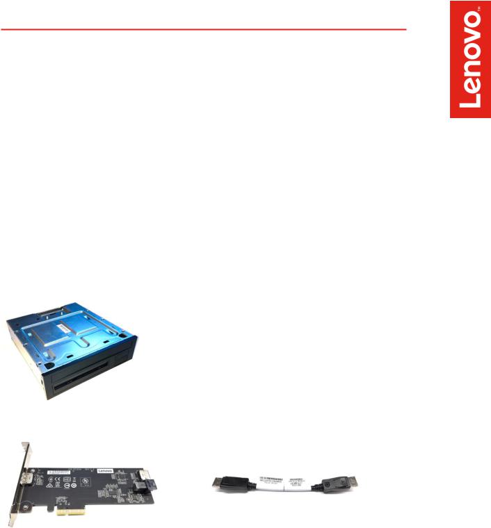
Thunderbolt 3 PCIe x4 card kit (FRU 01YW003)
PCIe x4 adapter card
External DP to DP cable
Front Panel IO board and cable kit (FRU 01YW016)
Front panel IO circuit board
General purpose input/output (GPIO) cable
Mini-SAS cable
Internal DP to DP cable
FLEX module
PCIe x4 adapter card |
External DP to DP cable (200mm) |
3

Front panel IO circuit board, bracket, and bezel
Cable connector details (total cable length) |
|
|
GPIO (600mm) |
Mini-SAS (650mm) |
Internal DP to DP (650mm) |
4

Installation instructions (front port solution)
Note: Due to differences in chassis design, portions of this installation procedure will vary depending on the type of workstation you have (P520c, P520, P720, or P920). Where necessary, the installation procedure differences are noted below.
FLEX module preparation
1.The FLEX module is designed with the removable access cover on the bottom. Invert the FLEX module so that the removable cover is facing up and then place it on a flat work surface. Lift the metal tab on the rear of the module and slide the cover back and up to remove it from the module.
2.When viewed from the front, the FLEX module faceplate has slots for 4 devices or ports. The Thunderbolt 3 ports will be installed in the top right slot (with the module oriented as shown below), which is currently filled by a blank bezel. Remove the blank bezel by pressing the two internal retaining tabs and popping the bezel out the front of the faceplate.
3.Install the Thunderbolt 3 bezel in the empty faceplate slot. The bezel should be oriented so that the Thunderbolt 3 icons are below the port openings in its current orientation. The module will be flipped over before it is inserted into the workstation, so these icons will be above the ports in the final orientation. Press the bezel from the front until the retaining tabs snap into place.
4.Remove the card retaining bracket from the FLEX module by lifting the retention clip slightly and sliding the bracket toward the rear of the module.
5
 Loading...