

Page 1
Page 2

Dear Customer,
Congratulations and thank you for choosing LANCIA.
We wrote this handbook to help you get the most out of your car’s outstanding qualities.
We advise to read it right through before taking to the road for the first time.
You will find information, tips and important warnings regarding the driving of your car to help you
derive the maximum from your LANCIA’s technological features. You will discover unique features and
details; you will also find essential information for car care and servicing as well as driving and operating safety not to mention the long-term wellbeing of your LANCIA.
The enclosed Warranty Booklet lists the services you have acquired and contains details relating to
the following:
• the Warranty Certificate, with terms and conditions for maintaining it
• the range of services offered to LANCIA owners.
We are sure that these instruments will help you easily attune to and appreciate both your new car
and the LANCIA team that will be on hand to provide you with any help you may require.
Best regards and have a great trip.
Page 3

MUST BE READ!
REFUELLING
Petrol engines: only refuel with unleaded petrol with octane rating (RON) no less than 95.
Diesel engines: only refuel with diesel fuel conforming to the European specification EN590.
ENGINE START-UP
Make sure the handbrake is pulled up; put the gear lever into neutral; press the clutch pedal down to the floor
without touching the accelerator; then:
petrol engines: turn the ignition key to AVV and release it as soon as the engine starts.
diesel engines: turn the ignition key to MAR and wait for the instrument panel warning lights ¢ and m
to go out, then turn the ignition key to AVV and release it as soon as the engine starts.
PARKING OVER INFLAMMABLE MATERIAL
When functioning normally, the catalytic converter reaches high temperatures. For this reason do not park
the car over inflammable material, grass, dry leaves, pine needles, etc.: fire hazard.
K
PROTECTING THE ENVIRONMENT
A system for continuously monitoring emission system components to ensure greater environmental
protection is fitted in your car.
U
Page 4

ELECTRICAL ACCESSORIES
If, after buying the car, you decide to add electrical accessories (that will gradually drain the battery), visit a
Lancia Dealership. They can calculate the overall electrical requirement and check that the car's electric
system can support the required load.
쇵
CODE card
Keep the code card in a safe place, not in the car. You should always keep the electronic code written on the
CODE card with you in case you need to carry out an emergency start-up procedure.
SCHEDULED SERVICING
Correct maintenance of the car is essential for ensuring it stays in tip-top condition and safeguards its safety
features, its environmental friendliness and low running costs for a long time to come.
THE OWNER HANDBOOK CONTAINS …
… information, tips and important warnings regarding the safe, correct driving of your car, and its
maintenance. Pay particular attention to the symbols " (personal safety) # (environmental protection) â
(the car’s wellbeing).
Page 5

TRAVELLING SAFELY AND IN HARMONY WITH NATURE
Safety and respect for the environment are the guidelines that inspired the Lybra’s design from the
drawing board onwards.
This concept has meant that the Lybra has been able to face and pass the strictest safety tests. So
much so that, from this point of view, the car is the best in its class and has probably already incorporated features that belong to the future.
In addition, ongoing research into new and effective features to help safeguard the environment
makes the Lybra and car to imitate for this reason as well.
All versions are in fact equipped with environmental protection devices that reduce harmful exhaust
fumes in compliance with the limits provided for by current legislation.
What is more, every single component of the Lybra is fully recyclable. At the end of your car’s lifespan any LANCIA dealership would be please to make arrangements for your car to be recycled.
Nature benefits in two ways: there is no pollution for waste disposal and the demand for raw materials is reduced.
Nature benefits in two ways: there is no pollution for waste disposal and the demand for raw materials is reduced.
Page 6

SAFEGUARDING THE ENVIRONMENT
Safeguarding the environment has directed the design and manufacturing of the Lybra right from
the start. The result is the use of materials and the perfection of devices that can reduce or sweepingly reduce harmful influences on the environment.
The Lybra, equipped with environment safeguarding devices which curtail harmful exhaust gas
emissions, is ready to travel well ahead of the most stringent international pollution control standards.
USE OF ENVIRONMENT-FRIENDLY MATERIALS
None of the car’s components contain asbestos. Padding and the climate control system do not
contain CFC (chlorofluorocarbides) - the gases considered responsible for the destruction of the
ozone layer. Other substances that might pollute air and water tables, such as the cadmium in the
rust-proof coating of the bolts and the chromates in some paints, have been completely replaced
with substances that do not harm the environment.
Page 7

DEVICES FOR REDUCING PETROL ENGINE EMISSIONS
Three-way catalytic converter (catalytic exhaust pipe)
Carbon monoxide, nitrogen oxides and unburned hydrocarbons are the main harmful components
in exhaust gasses.
The catalytic converter is a “miniature laboratory” where a very high percentage of these components are converted into harmless substances.
This conversion is aided by minute particles of precious metals on the ceramic core enclosed in a
stainless steel container.
Lambda sensor
All petrol versions are fitted with this device. It ensures that air and fuel are constantly mixed in
the correct proportion. This is a fundamental condition for proper engine and catalytic converter
operation.
Fuel evaporation canister
As it is impossible to stop the build up of petrol fumes, also when the engine is not running, the
system traps them in a special container holding active carbon. The fumes are sucked in from here
and burnt while the engine is running.
Page 8

DEVICES FOR REDUCING DIESEL ENGINE EMISSIONS
Oxidising catalytic converter
This device converts the pollution substances in the exhaust gas (carbon monoxide, unburned
hydrocarbons and particulate) into harmless substances, thus reducing the smokiness and smell
associated with diesel engine exhaust fumes.
The catalytic converter consists of a stainless steel case containing a honeycomb ceramic core in
which there is precious metal which carries out the catalysing action.
Exhaust Gas Recirculation (E.G.R. Cooled) system
This system recirculates or reuses part of the exhaust gas in a proportion which varies according to
engine operation conditions.
When necessary, it is used for the control of nitrogen oxide emissions.
Page 9

THE SIGNS TO HELP YOU DRIVE CORRECTLY
The signs you see on this page are very important. They highlight those parts of the handbook
where, more than elsewhere, you should stop for a minute and read carefully.
As you can see, each sign has a different symbol to make it immediately clear and easy to identify
the subjects in the different areas:
Personal safety.
Important. Total or partial failure to
follow these instructions can place
driver, passengers or others in serious
danger.
Environmental protection.
This shows you the correct procedures
to follow to ensure that the car does
not harm the environment.
Car wellbeing.
Important. Total or partial failure to
follow these instructions will result in
the risk of serious damage to the car
and may invalidate the warranty as
well.
Page 10

9
Battery
Corrosive fluid.
SYMBOLS
Special coloured labels have been attached near or actually on some of the
components of your Lybra. These labels bear symbols that remind you of
the precautions to be taken as regards
that particular component.
A list of the symbols to be found on
your Lybra is given below with the
name of the component to which it relates at the side of it.
These symbols are divided into the
following four categories: danger, prohibition, warning and obligation.
DANGER SYMBOLS
Battery
Explosion.
Fan
May cut in automatically
even when the engine is
turned off.
Expansion tank
Do not remove the cap
when the coolant is hot.
Coil
High voltage.
Belts and pulleys
Moving parts: keep parts
of the body and clothes
away.
Climate control tubing
Do not open. Gas under
high pressure.
Page 11

10
Battery
Keep away from naked
flames.
Battery
Keep away from chil-
dren.
Heat shields - belts pulleys - fan
Do not touch.
PROHIBITION SYMBOLS
Power steering
Do not exceed the maximum fluid level in the
reservoir. Use only the fluid
specified in the section
“Capacities”.
Catalytic converter
Do not park over inflammable materials. See Chapter: “Protecting the emission control devices”.
WARNING SYMBOLS
Engine
Use only the oil specified in
the section “Capacities”.
Unleaded petrol vehicle
Use only unleaded petrol
with a rated octane number
(RON) of 95.
Windscreen wiper
Only use fluid of the type
specified in the section “Capacities”.
Brake circuit
Do not exceed the maximum fluid level in the
reservoir. Use only the fluid
specified in the section
“Capacities”.
Page 12

11
Diesel engines
Use diesel fuel only.
Expansion tank
Only use fluid of the type
specified in the section “Capacities”.
Battery
Protect your eyes.
Battery
Jack
See the Owner handbook.
OBLIGATION SYMBOLS
DIESEL
Page 13

Page 14

13
GETTING TO KNOW YOUR CAR
DRIVING YOUR CAR
IN AN EMERGENCY
CAR MAINTENANCE
LYBRA STATION WAGON
TECHNICAL SPECIFICATIONS
ACCESSORY INSTALLATION
INDEX
CONTENTS
Page 15

GETTING TO KNOW YOUR CAR
You are recommended to read this chapter
sitting comfortably in your new Lybra. In this
way you will be able to identify the parts
described immediate and see for yourself what
you have just read.
In short, you will increase your knowledge of
your Lybra with its controls and other devices.
Later, when you start the engine and join the
traffic you will make a host of other pleasant
discoveries.
DASHBOARD.................................................. 15
IGNITION SWITCH ........................................ 16
THE LANCIA CODE SYSTEM........................ 17
THE ELECTRONIC ALARM .......................... 21
INDIVIDUAL SETTINGS................................ 28
SEAT BELTS................................................... 34
TRANSPORTING CHILDREN IN SAFETY..... 37
PRETENSIONERS .......................................... 42
FRONT AND SIDE AIRBAGS.......................... 43
INSTRUMENT PANEL.................................... 50
INSTRUMENTS .............................................. 51
WARNING LIGHTS......................................... 53
CHECK CONTROL......................................... 59
LANCIA ICS WITH MULTIFUNCTIONAL
DISPLAY ......................................................... 62
SOUND SYSTEM ............................................ 73
CLIMATE CONTROL SYSTEM ...................... 103
AUTOMATIC CLIMATE
CONTROL SYSTEM ....................................... 105
SUPPLEMENTARY HEATER ......................... 115
STEERING COLUMN STALKS....................... 115
CONTROLS .................................................... 118
MANUAL GEARBOX ...................................... 121
CRUISE CONTROL ........................................ 122
INTERIOR EQUIPMENT ................................ 125
SUNROOF....................................................... 131
DOORS............................................................ 134
BOOT .............................................................. 138
BONNET ......................................................... 141
FUEL FILLER CAP ........................................ 143
CELLULAR PHONE SET-UP ......................... 144
ROOF RACK AND SKI RACK ......................... 145
ADJUSTING THE HEADLIGHTS................... 146
EOBD SYSTEM .............................................. 148
ABS ................................................................. 149
ESP SYSTEM (ASR - HH - HBA).................... 151
SOUND SYSTEM DEVICES............................ 154
14
Page 16

15
DASHBOARD
The presence and the position of the instruments and warning lights may vary according to the version.
1) Side window vents - 2) Side vents - 3) Headlight slant adjuster - 4) Instrument panel - 5) Instrument panel dimmer - 6) ICS multifunctional display: sound system, clock, trip computer and check control - 7) Central vents - 8) Windscreen vent - 9) Passenger’s airbag (where
fitted) - 10) Passenger’s airbag deactivation switch - 11) Glove compartment - 12) Cup/can holder - 13) Hazard light switch - 14) Automatic climate control and heated rear window switch - 15) Ashtray and cigar lighter - 16) Front and rear fog light switch - 17) Card pocket -
18) Windscreen wiper/washer stalk - 19) Ignition switch - 20) Horn - 21) Steering wheel height adjustment lever - 22) Driver’s airbag -
23) Outside light control stalk - 24) Glove compartment/fusebox cover - 25) Bonnet opening lever.
P4T0806
fig. 1
Page 17

16
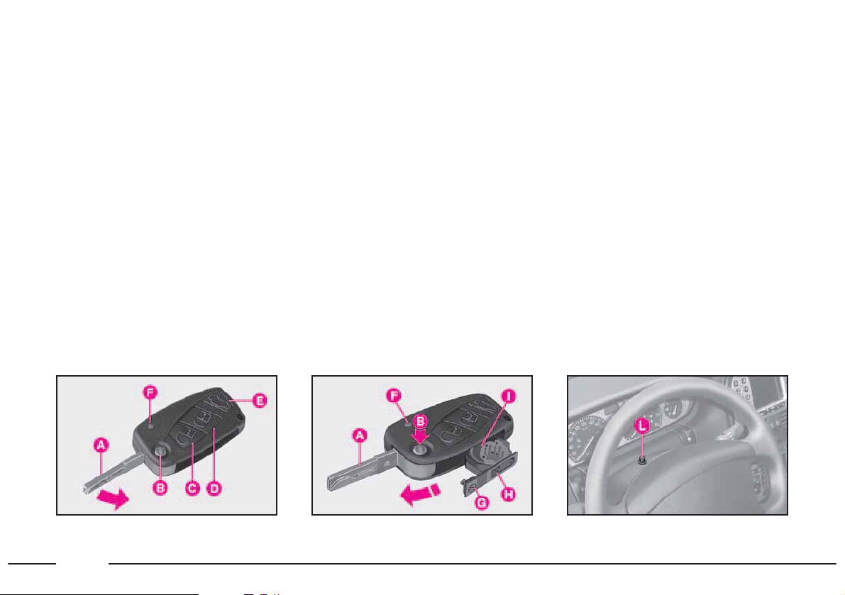
IGNITION SWITCH
The key can be turned to four posi-
tions (fig. 2).
STOP: engine off, key can be removed, steering column locked. Some
electrical devices can be worked (e.g.
sound system).
MAR: driving position. All electrical
devices can be worked.
AVV: engine ignition.
PARK: engine off, parking lights on,
key can be removed, steering column
locked. To turn the key to PARK,
press button A.
STEERING COLUMN LOCK
To engage the lock: remove the ig-
nition key at STOP or PARK and
turn the steering wheel until it locks.
To release the lock: rock the steering wheel slightly as you turn the ignition key to MAR.
fig. 2
P4T0005
If the ignition switch has
been tampered with (e.g.
someone has tried to steal
your car), get a Lancia Dealership
to make sure it is still functioning
properly before you start driving
again.
Always remove the ignition key when you get out
of the car. This will pre-
vent anyone from accidentally
working the controls. Remember
to apply the handbrake and, if the
car is faced down on a steep slope
engage the first gear. If it is facing
up, engage the reverse gear.
Never remove the ignition
key while the car is moving. The steering wheel
would automatically lock as soon
as you try to turn it. This also applies when the car is being towed.
It is absolutely forbidden
to carry out whatever after-market operation in-
volving steering system or steering
column modifications (e.g.: installation of anti-theft device) that
could badly affect performance
and safety, cause the lapse of warranty and also result in non-compliance of the car with homologation requirements.
Page 18
In order to ensure the
greatest efficiency of electronic devices incorpo-
rated in the key, it is recommended that the latter should not
be exposed to direct sunlight
and/or heavy shocks.
THE LANCIA CODE
SYSTEM
To further protect your car from
theft, it has been fitted with an engine
immobilising system (Lancia CODE)
which is automatically activated when
the ignition key is removed. An electronic device, in fact, is fitted in each
ignition key grip. The device transmits a radio-frequency signal when
the engine is started through a special
aerial built into the ignition switch.
The modulated signal is a password.
Only if the control unit recognises the
key can the engine be started.
KEYS
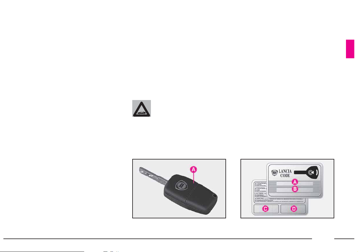
Together with the car are delivered:
– 2 keys A (fig. 3) with incorporated
remote control if the car is fitted with
an electronic alarm;
– 1 key with incorporate remote control plus 1 mechanical type key if the
car is not fitted with an electronic
alarm.
The CODE card (fig. 4) is also supplied with the keys and bears the following:
A - The electronic code, to be used
for emergency starting.
B - The mechanical key code to be
given to the Lancia Dealership
when ordering duplicate keys.
C and D - The spaces for electronic
alarm remote control stickers.
The code numbers written on the
CODE card must be kept in a safe
place (not in the car).
You should always have the electronic code number written on the
CODE card with you at all times in
case you need to perform an emergency start-up.
17
fig. 3
P4T0742
fig. 4
P4T0743
Page 19
18
All the keys and the CODE
card must be handed over
the new owner when selling
the car.
IMPORTANT Anomalous glass op-
eration (glasses sliding up or down
jerkily) may indicate a loss of calibration of the anti-crushing safety device. In this case, the system should
be reinitialised as described in chapter “Electric window winders” in the
Owner Handbook, to which this Supplement is attached to.
The metal insert A (fig. 6) of the key
operates:
– the ignition switch;
– the steering column lock disen-
gagement;
– the driver’s door lock;
– the boot lock;
– button D, to operate the central
door locking system, boot/tailgate
locking, to switch the electronic alarm
on (where fitted) and to lock the fuel
filler cap;
– button E, to open the boot/tailgate
when the alarm is on;
– led F, which indicates the remote
control operation and the internal
battery status.
Pressing down (for more than 2 seconds) button C will open all door windows to aerate the passenger compartment: window opening is interrupted when the button is released.
Similarly, door windows can be
completely closed when closing the
doors by pressing down (for more
than 2 seconds) button D.
Window closing is stopped when releasing button D.
The key (fig. 5) is provided with:
– a metal insert A that can be locked
up in the key handle by pressing button B;
– button B, used to snap-open the
metal insert;
– button C, to operate the central
door locking system, to switch the
electronic alarm off (where fitted) and
to unlock the fuel filler cap;
fig. 5
P4T0744
fig. 6
P4T0745
Page 20

19
– the passenger’s side air bag deactivating switch;
– the glove compartment lock
(where fitted).
To remove the metal insert from the
key grip, press button B.
When pressing button B
(fig. 6), take care to prevent
the metal insert A from
causing harm or damage when it
comes out. The button B should
only be pressed when the key is
away from the body, in particular
from the eyes, and from objects
that can be spoilt (e.g. clothes).
Make sure the key can never be
touched by others, especially children, who may inadvertently press
the button B.
2) If the ¢ warning light stays on
(withUwarning light) the code was
not recognised. In this case, turn the
key to STOP and then back to MAR.
If the engine remains immobilised, try
with the other keys provided.
If you are still unable to start the engine, carry out the emergency starting
procedure and contact your Lancia
Dealership.
When the car is travelling and the
key is at MAR:
1) If the ¢ warning light comes on
while the car is moving, this means
that the system is running a self-test
(e.g. due to a voltage drop). The first
time you stop, you can test the system
as follows: switch off the engine by
turning the ignition key to STOP then
turn the key back to MAR: the warning light ¢ should come on and then
go out in about one second. If the
warning light fails to go out, leave the
key at STOP for longer than 30 seconds. If the problem persists, contact
a Lancia Dealership.
To insert the metal insert A (fig. 5)
into the key grip, keep the button B
pressed and turn the insert in the direction shown by the arrow until
hearing the locking click. Then release
button B.
OPERATION
Each time the ignition key is removed from position STOP, or
PARK, the Lancia CODE system will
deactivate the engine electronic control unit functions.
When the key is turned to MAR to
start the engine, the Lancia CODE
system sends a password code to the
engine control unit to deactivate the
function lock. The encoded and variable code, randomly selected from
over four billion possible combinations, is only sent if, in turn, the system has recognised the code transmitted by the electronic device built
into the ignition key via an aerial surrounding the ignition switch.
1) If the code is recognised, the ¢
warning light on the instrument panel
will flash briefly: this means that the
protection system has recognised the
key code and disabled the engine immobilising system; turn the key to
AVV, to start.
Page 21

20
2) If the warning light ¢ flashes, the
car is not protected by the engine immobilising system. Contact a Lancia
Dealership immediately and get
them to store the codes of all the keys
in the memory.
REPLACING THE BATTERIES
Replace the batteries with equivalent
batteries which can be purchased at
common stores, if the key led F
flashes briefly once and led L (Fig.
12) in front of the steering wheel stays
on with fixed light for approximately
two minutes (after switching the
alarm off), when button (C, D or E
fig. 5) is pressed.
DUPLICATE KEYS
When you ask for extra keys, remember that all the keys, both the new
ones and those you already possess,
must be stored in the memory (up to a
maximum of seven keys). Go directly
to your Lancia Dealership, taking
with you all the keys in your possession, the CODE card, personal ID and
the car’s ownership papers. Copies of
the CODE card can be ordered from
your Lancia Dealership.
IMPORTANT The codes of any
keys that are not available when the
new storage procedure is carried out
will be deleted from the memory to
prevent any lost or stolen keys being
used to start the engine.
Used batteries pollute the
environment. Dispose of
them in the special con-
tainers, as specified by current legislation or take them to a Lancia
Dealership, which will deal with
their disposal.
If the Lancia CODE
warning light flashes at
half a second frequency
after approximately two seconds
from when the key is turned to
MAR, the key code has not be
stored in the system’s memory and
consequently the car is not protected by the Lancia CODE system
against theft. In this case, go to a
Lancia Dealership to have the key
codes stored.
IMPORTANT The code may not
be completely transmitted if the
key is turned very rapidly from
STOP to AVV. This will prevent
the engine from starting. Try again
turning the key slower.
Page 22

21
fig. 8
P4T0748
fig. 7
P4T0747
Replace the batteries as follows:
– press button B (fig. 7) and bring
the metal insert A to the open position;
– by means of a fine tip screwdriver,
turn the opening device G to : and
remove the battery holder H;
– replace the battery I observing the
proper bias;
– refit the battery holder into the key
and secure it, by turning the device G
to ;.
ELECTRONIC ALARM (where fitted)
The electronic alarm system fitted in
the car complies with EC directive
95/56 and consists of:
– a radio-frequency transmitter
(built into the ignition key);
– a radio-frequency receiver;
– an electronic control unit with
built-in siren;
– volumetric sensors which can be
deactivated (built-into the front ceiling lamp);
– an anti-lifting sensor;
– a bonnet opening switch;
– boot/tailgate opening switch;
– door opening switches;
– warning LEDs.
The electronic alarm is controlled by
the receiver and is switched on by
pressing button D (fig. 8) and switched
off by pressing button C. Both buttons
are built-into the ignition key, which
sends the secret and variable code.
The electronic alarm - which additionally operates the central door
locking system - protects from the following actions:
– illicit opening of doors, bonnet and
boot (perimetral surveillance);
– ignition switch operation;
– moving bodies in the passenger
compartment (volumetric surveillance);
– attempts to lift the car;
– cutting of battery cables.
The volumetric surveillance function
can be deactivated, as required. Follow the instructions given below.
Page 23
22
fig. 9
P4T0807
IMPORTANT The engine immobilising system is governed by the Lancia CODE system and is automatically
activated when the ignition key is removed.
REMOTE CONTROL (fig. 8)
The remote control is built into the
ignition key and is equipped with:
– button D for switching the alarm on;
– button C for switching the alarm off;
– button E for opening the boot with
the alarm on;
– LED F.
The buttons operate the control and
the LED flashes while the transmitter
is sending the code to the receiver.
This code (of the “rolling code”
type) is encoded by means of a specific algorithm and consequently
changes at each transmission.
The radio-frequency remote control
allows to operate the alarm system
also from a certain distance (up to approximately 10 metres from the car),
without the need of being addressed
towards the receiver and also if the
windows are dirty.
IMPORTANT Change the remote
control batteries as soon as possible if
LED F flashes briefly only once when
button D is pressed. The LED will
work normally after button D is
pressed for the second time after replacing the batteries.
SWITCHING THE ALARM ON
The alarm can only be switched on
with the ignition key at STOP, PARK
or removed.
To switch the alarm on, press and
release button D (fig. 8) on the igni-
tion key.
With the exception of certain markets,
a beep will be heard, the direction indicators will light up for approximately
three seconds, the doors will be locked
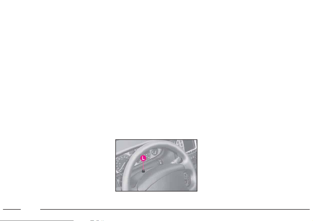
and LED L (fig. 9) in front of the steering wheel will start flashing.
A self-test is run when the alarm is
switched on. The test is signaled by
LED L which flashes as follows:
– four flashes in one second: no
faults found;
– eight flashes in one second:
door/bonnet/boot open or faulty sensor;
– fixed light: faulty volumetric or
anti-lift sensor.
If a fault is found, the concerned
component is cut out and the system
beeps to signal the event.
Surveillance
LED L (fig. 9) will flash to indicate
that the system surveillance function
is on.
The LED will flash as long as the
system is operating.
IMPORTANT The electronic alarm
operation is adapted to the rules in
force in the various countries.
Page 24

23
Self-test
and door/bonnet/boot checks
Check that the doors, bonnet and
boot are correctly closed if a second
beep is heard when the alarm is
switched on. Then try to switch the
alarm back on.
The system will cut out the doors,
bonnet and boot from the surveillance
if they are not properly closed.
If the doors, the bonnet and the boot
are properly closed and the second
beep is heard again, it means that the
system self-test function has found a
fault. Contact a Lancia Dealership.
SWITCHING ON THE ALARM
AND CUTTING OUT THE
VOLUMETRIC SURVEILLANCE
The function can be cut out (for example, when pets are left in the car) by
carrying out the following operations
in rapid sequence. With the key at
MAR, turn the key to STOP, then
back to MAR and then back to STOP
again. Remove the ignition key. The
LED in front of the steering wheel will
light up for approximately two seconds
to indicate the function has been cut
out.
To restore the volumetric surveillance function, take the key to MAR
and hold it there for longer than 30
seconds.
If you want to operate an electrical
device which runs when the key is at
MAR (e.g. the electrical window
winders) when the volumetric surveillance function is cut out, turn the
key to MAR, operate the required
control and turn the key back to
STOP within 30 seconds. In this way
the the volumetric surveillance function will not be switched on again.
AUTOMATIC SWITCH-ON
(where fitted)
In some markets, the electronic
alarm can be programmed to be
switched on automatically.
The electronic alarm is automatically switched on (without operating
the door locking system) after approximately 30 seconds from when
the car is left. This condition is detected by the system by the following
sequence of actions:
– ignition key turned from MAR to
STOP;
– opening and closing of the last
door.
The automatic switch-on will be interrupted if a door, the bonnet or the
boot is opened during the 30 second
timeout. The 30 seconds timeout will
start from zero after closure.
Press button C (fig. 8) on the ignition key to switch the alarm off after
an automatic switch-on.
Page 25

24
SWITCHING THE ALARM OFF
To switch the alarm off, press remote control button C (fig. 8). Then,
the system performs the following actions (with the exception of certain
markets):
– the direction indicators will flash
twice;
– two short siren sound signals
(“BEEP”);
– the system will unlock the doors.
IMPORTANT If LED in the car
stays on (for up to two minutes or until the ignition key is turned to MAR)
when the alarm is switched off:
– If the LED stays on (fixed light) the
remote control batteries are flat. Replace them.
– If the LED flashes differently
from usual, an attempt has been
made to break into the car. The type
of break-in attempt is signalled by the
number of flashes:
1 flash: front right-hand door
2 flashes: front left-hand door
3 flashes: rear right-hand door
4 flashes: rear left-hand door
5 flashes: volumetric or anti-lifting
sensors
6 flashes: bonnet
7 flashes: boot/tailgate
8 flashes: tampered wires to start en-
gine
9 flashes: tampered battery wires
10 flashes: three or more causes of
alarm.
VOLUMETRIC PROTECTION
Do not leave passengers or pets in the
parked car and completely close the
windows and the sunroof (where fitted)
to ensure the correct operation of the
volumetric sensors. Furthermore, make
sure that the doors, bonnet and
boot/tailgate are properly closed.
ANTI-LIFTING SENSOR
The anti-lifting sensor detects variations in slant to signal lifting or partial lifting (e.g. to remove a wheel) of
the car.
The sensor can detect minimal variations in car trim along both longitudinal axis and transversal axis. variations in trim lower than 0.5°/min.
(such as, for example, a slow deflating tyre) are not taken into account.
Page 26

25
OPENING THE BOOT WHEN
THE ALARM IS ON
When the alarm is on, the boot can
be opened by pressing button E
(fig. 8) on the ignition key.
In this case, the operating logic of
the alarm is as follows:
– the volumetric surveillance function is deactivated;
– the anti-lift sensor is deactivated;
– the boot/tailgate sensor is deactivated.
The normal surveillance functions
are reactivated when the boot/tailgate
is closed.
WHAT TRIGGERS
THE ALARM OFF
The alarm will be triggered off in the
following conditions:
– if a door, the bonnet or the
boot/tailgate is opened;
– if the battery or the cables are dis-
connected or cut;
– if there is an intrusion in the passenger compartment, e.g. a broken
window (volumetric protection).
– if an attempt is made to start the
engine (key at MAR);
– if an attempt has been made to lift
the car.
According to the markets, the alarm
can operate the siren (for up to three
26 second cycles) and the direction
indicators (for approximately four or
five minutes, only where this is allowed). The intervention modality
and the number of cycles can vary according to the markets.
A maximum number of acoustic/visual cycles is foreseen in all cases.
After the alarm cycle, the system returns to its normal surveillance function.
STOPPING THE ALARM
To stop the alarm, press button C
(fig. 8) on the remote control. If this
is unsuccessful, owing to run-down
remote control battery or to a system
fault, open the door after unlocking
the lock with the key, then put the
key into the ignition switch and turn
it to MAR.
To switch the alarm on again, turn
the key to STOP and remove it, then
press button D on the remote control
after closing the doors. If the alarm is
not switched on and LED F on the remote control gives off only a short
flash, the key battery needs replacing.
To replace the battery, follow the instructions shown in chapter “Lancia
CODE System”.
If, with the remote control battery
charged, the alarm cannot be
switched on, contact your Lancia
Dealership to have the system
checked.
Page 27
26
IMPORTANT If the car is to be
stored for a long period of time (over
three weeks) and safety conditions
permitting, it is recommended that
central locking is actuated by turning
the key in the door lock, so as not to
switch the alarm on and, thus, avoid
running down the battery.
fig. 10
P4T0744
fig. 11
P4T0747
fig. 12
P4T0807
Replace the batteries as follows:
– press button B (fig. 11) and bring
the metal insert A to the open position;
– by means of a fine tip screwdriver,
turn the opening device G to : and
remove the battery holder H;
– replace the battery I observing the
proper bias;
– refit the battery holder into the key
and secure it, by turning the device G
to ;.
REPLACING THE BATTERIES
Replace the batteries with equivalent
batteries which can be purchased at
common stores, if the key led F
flashes briefly once and led L (fig. 12)
in front of the steering wheel stays on
with fixed light for approximately two
minutes (after switching the alarm
off), when button (C, D or E fig. 10)
is pressed.
Page 28

27
Used batteries pollute the
environment. Dispose of
them in the special con-
tainers, as specified by current legislation or take them to a Lancia
Dealership, which will deal with
their disposal.
REQUEST FOR ADDITIONAL
REMOTE CONTROLS
The receiver will acknowledge up to
8 remote controls.
If extra remote controls are ordered,
in addition to the ones originally supplied, remember to carry out the same
programming procedure for all the remote controls when the car is new.
The control unit will subsequently
exclude this type of programming to
prevent anyone else programming the
control unit to acknowledge other remote controls.
If, therefore, you ever need a new remote control, go directly to a Lancia
Dealership, taking with you all the
keys in your possession, the CODE
card, personal identification and the
car ownership papers.
MINISTERIAL HOMOLOGATION
In the respect of the legislation in
force in each country in the matter of
radio-frequency devices, please note
that:
– the market-specific homologation
numbers are listed in the following
section: Radio-frequency remote control: ministerial homologation;
– the homologation number is
printed on the component for markets
where this is required.
The code marking may also be
printed on the transmitter and/or the
receiver for versions/markets where
this is required.
Page 29
28
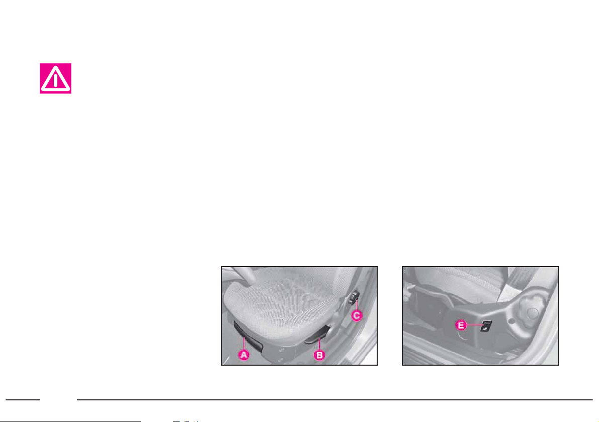
INDIVIDUAL
SETTINGS
Height adjustment
Lift or lower lever B repeatedly to
raise or lower the seat.
Adjusting the reclining seat back
Turn knob C forwards or backwards
to straighten or recline the seat back.
Lumbar adjustment
Press button E (fig. 14) to adjust the
driver’s seat lumbar support.
ELECTRICALLY
ADJUSTABLE SEATS
(where fitted) (fig. 15)
Only make adjustments of the driver’s seat when the car is stationary.
The adjustment is only possible when
the ignition key is at MAR (with the
exception of the driver’s seat back
fore/aft adjustment, the height adjustment and seat back adjustment).
Use controls A and B (fig. 15):
¯˙ to adjust the seat forwards and
backwards (control A);
Only adjust the driver’s
seat when the car is stationary.
MANUALLY ADJUSTABLE
FRONT SEATS (fig. 13-14)
Moving the seat backwards or
forwards
Lift lever A (fig. 13) and push the
seat backwards or forwards; you are in
the correct position for driving when
your hands are resting on the steering
wheel rim and your arms are slightly
bent. Once you have released the lever,
check that the seat is firmly locked in
the runners by trying to move it back
and forth. Failure to lock the seat in
place could result in the seat moving
suddenly and dangerously.
fig. 13
P4T0007
fig. 14
P4T0270
Page 30

29
to adjust the height of the front
and rear part of the driver’s seat
and the rear part only of the passenger’s seat (control A);
¯˙to adjust the seat back (control B).
Driver’s seat lumbar adjustment
This device makes it possible to vary
back support and improve comfort.
Press the front part of the button C (fig.
15) to increase the support and the rear
part of the button to decrease it.
Heating (where fitted)
Press button D (fig. 15) to switch
the seat heating on. Press the button
again to switch it off.
The LEDs on the dashboard will
light up (A-fig. 16 = driver’s seat, B =
passenger’s seat).
Storing the driver’s seat positions
(where fitted-fig. 17)
The system allows to store and recall
two different driver’s seat and external rearview mirror positions.
The seat and rearview mirror position can only be stored when the ignition key is at MAR.
Adjust the driver’s seat position and
the external rearview mirrors as described.
Press button “MEM” and either button “1”, “2” or “3” corresponding to
each of the stored positioned at the
same time until two confirmation
beeps are heard.
The previously stored position will
automatically be deleted when a new
position is stored under the same button.
To recall a position, press the respective button “1”, “2” or “3” with
the door open. The seat will move automatically and stop when the stored
position is reached. A confirmation
beep will be heard.
IMPORTANT The lumbar adjustment and the seat heating function
are not controlled by the stored seat
position system.
fig. 15
P4T0333
fig. 16 fig. 17
P4T0271
P4T0332
Page 31

30
Rear central seat
Versions with single seat (fig. 22):
To improve passenger safety the
height of the head restraint can be adjusted.
To raise it, grip the head restraint at
the base and pull it upwards completely until hearing a click.
To lower it, press it downwards
keeping button A pressed until hearing a click.
Versions with twin seat (fig. 23):
To adjust the rear central head restraint height, lift it from its housing
until hearing a click.
Remember that the head
restraints should be adjusted to support the back
of your head and not your neck.
Only if they are in this position will
they be able to provide effective
protection in the event of a rearend shunt.
fig. 19
P4T0232
fig. 20
P4T0701
fig. 21
P4T0702
HEAD RESTRAINTS (fig. 19)
To improve passenger safety, the
height of the front and rear side head
restraints can be adjusted so that the
head rests on them properly.
Front seats (fig. 20)
To adjust the front head restraint
height, move it upwards to the required position. To lower the front
head restraint, keep button A depressed and return it to the required
position. The front head restraints can
be adjusted for tilt by moving them in
the direction of the arrows as shown
in the figure below. Front head restraints are not removable.
Rear side seats (fig. 21)
To adjust the rear side head restraint
height, lift it from its housing until
hearing a click.
To bring it back to the original position: press buttons A and lower the
head restraint until it fits into the seat
back.
Page 32

31
FRONT ARMREST (fig. 24)
The armrest can be adjusted up or
down.
To use the armrest, lower it as
shown in the figure.
An oddment compartment is concealed inside the armrest. Press button A to lift the cover.
IMPORTANT When the armrest
has been lifted completely, take care
not to accidentally press button A,
otherwise you will open the object
tray cover and the contents will fall
out.
REAR ARMREST (fig. 25)
Lower the armrest to the position
shown for use by lowering the lever on
the armrest.
To close, lift the armrest into its
housing.
fig. 24
P4T0808
fig. 25
P4T0014
fig. 23
P4T0735
fig. 22
P4T0012
To raise it easily, grip the head re-
straint from the back.
To bring it back to the original position: press buttons A and lower the
head restraint until it fits into the seat
back.
Page 33

32
STEERING WHEEL (fig. 27)
The steering wheel height and axial
position can be adjusted.
1) Move lever A to position 1.
2) Adjust the steering wheel (by
pulling, pushing, lifting or lowering
it).
3) Return the lever to position 2 to
lock the wheel in place.
Only make adjustments
when the car is stationary.
INTERNAL REARVIEW MIRROR
Manually adjustable (fig. 28)
This mirror can be adjusted in four
directions by means of lever A:
1) normal position
2) anti-dazzle position.
The mirror is also fitted with a safety
device that releases the mirror in the
event of an impact.
Automatically adjustable
(where fitted-fig. 29)
This mirror is automatically set to
day and night position.
fig. 27
P4T0809
fig. 28
P4T0272
fig. 29
P4T0016
On versions with single seat the rear
armrest is equipped with glass-tin
holder (fig. 26).
fig. 26
P4T0734
Page 34

33
If the mirrors make it difficult to get through narrow gaps and in automatic
car washes, fold them from position 1 to position 2 (fig. 32).
EXTERNAL REARVIEW
MIRRORS (fig. 30-31-32)
These mirrors can only be adjusted
when the ignition key is at MAR.
Turn switch A (fig. 30-31) to posi-
tion 1 (left-hand mirror) or to position 2 (right-hand mirror) to select
the mirror to be adjusted.
Press switch A to adjust the mirror
in the four directions.
After adjusting, turn switch A back
to position 0 to prevent moving the
mirrors accidentally.
fig. 30
P4T0056
fig. 31
P4T0029
fig. 32
P4T0017
The mirrors are automatically demisted/ defrosted when the heated rear
window is operated.
IMPORTANT The curve of the mirror surface makes objects seem further away than they actually are.
Storing rearview mirror
positions (where fitted)
The external rearview mirror position is stored along with the driver’s
seat position in versions fitted with a
driver’s seat electrical adjustment and
storing feature.
The mirrors can be folded manually
or electrically (where fitted) to reduce
side clearance.
Turn switch A (fig. 31) to position 3
to fold the mirrors electrically (where
fitted). Turn the switch to position 0
to return the mirrors to their normal
position.
Page 35

34
SEAT BELTS
HOW TO USE
THE SEAT BELTS
(front and rear seats - fig. 33)
To fasten the seat belts, take the
tongue of fastener A and push it into
buckle B, until you hear it click.
Pull the seat belt gently. If it jams,
let it rewind a little and pull it out
again without jerking.
Instrument panel warning light <
will come on if the ignition key is
turned to MAR and the driver’s seat
belt is not fastened.
To release the seat belts, press
button C. Guide the seat belt with
your hand while is rewinding to prevent it from twisting.
The seat belt reel mechanism ensures that the belt automatically adjusts to the wearer allowing him or
her to move in complete freedom.
When the car is parked on a steep
slope the reel mechanism may block;
this is normal.
Only adjust seat belt
height when the car is stationary.
The reel mechanism prevents the
webbing coming out when it is jerked
or if the car brakes sharply, is in a
collision or when cornering at high
speed.
ADJUSTING THE HEIGHT OF
THE SEAT BELTS (fig. 34)
Always adjust the height of the front
seat belt to fit the person wearing it.
This could greatly reduce the risk of
injury in the case of collision.
The belt is adjusted properly when
the webbing passes approximately
halfway between the edge of the
shoulder and the neck.
The seat belt can be adjusted to one
of five different heights.
fig. 33
P4T0019
fig. 34
P4T0018
For maximum safety,
keep the back of your seat
upright, lean back into it
and make sure the seat belt fits
closely across your chest and hips.
Never press button (C)
when travelling.
Page 36

35
USE OF THE REAR SEAT
BELTS
The rear seat belts must be
worn as shown (fig. 35).
You should put the belt on when you
are sitting upright and leaning back
in your seat.
When no-one is sitting in the rear
seats, carefully fold the belts and
buckles and stow them away in the
receptacles in the seat back.
To raise the belt
Lift loop A to the required position.
To lower
Press button B and move loop A
downwards at the same time to the
required position.
After adjustment, always
check that the slider is anchored in one of the posi-
tions provided. To do this, with the
button released, exert a further
pressure to allow the anchor device to catch if release did not take
place at one of the preset positions.
fig. 35
P4T0703
FRONT SEAT BELT LOAD
LIMITING DEVICE
In order to increase passive safety,
the front seat belt reels have a builtin load limiting device which collapse
in a controlled fashion so to dose the
force on the passenger’s shoulder during retaining operation.
Page 37

36
Remember that in the
case of a violent collision,
back seat passengers not
wearing seat belts also represent a
serious danger to the passengers in
the front.
Proper backrest coupling
is guaranteed when each
handle (B – fig. 35 / a) and
(C – fig. 35 / b), is retracted in its
housing.
Make sure the seat back
is correctly hooked on
both sides to prevent seat
back being thrown forwards and
injuring passengers should you
brake sharply.
GENERAL INSTRUCTIONS FOR
THE USE OF THE SEAT BELTS
The driver is responsible for respecting and enforcing the local rules
and laws regarding the use of seat
belts.
Make sure the seat belts
of the front and rear passengers are fastened at all
times. You increase the risk of serious injury or death in a collision
if you travel with the belts unfastened.
fig. 35/a
P4T0205
fig. 35/b
P4T0206
Page 38

37
Seat belts must also be worn by expectant mothers: the risk of injury in
the case of accident is much greater
for them and their unborn child too if
they do not have a seat belt on. Of
course, they must position the lower
part of the belt very low down so that
it passes under the abdomen (fig. 37).
HOW TO KEEP THE SEAT
BELTS IN PROPER WORKING
ORDER AT ALL TIMES
1) When wearing the seat belts, al-
ways ensure they are not twisted and
are free to wind in and out.
2) Following a serious accident, replace the belt being worn at the time,
even if it does not seem damaged.
3) When cleaning the belts, wash
them by hand with water and neutral
soap, rinse them and let them dry in
the shade. Do not use strong detergents, bleach, colourings or any other
chemical substance that could weaken
the fibres.
4) Do not allow the reel mechanisms
to get wet: they are only guaranteed
to work properly if they remain dry.
fig. 37
P4T0043
fig. 38
P4T0044
Never travel with a child
sitting on the passenger’s
lap with a single belt to
protect them both (fig. 38).
fig. 36
P4T0042
The webbing must not be
twisted. The upper section
must pass across the
shoulder and chest diagonally. The
lower part must fit closely across
the passenger’s hips and not the
abdomen, to prevent them from
sliding forwards (fig. 36). Do not
use clips, fasteners etc. to prevent
the belt adhering to the passenger’s
body.
IMPORTANT Arrange the child re-
straint seat on the rear seat behind the
passenger’s seat. This is the most protected position in the passenger compartment in the event of a collision.
Page 39

38
CARRYING
CHILDREN
SAFELY
passenger’s air bag, which during
inflation could cause serious injury, even mortal, regardless of the
seriousness of the crash that triggered it. Children may be placed
on the front seat of cars fitted with
passenger’s air bag deactivation.
In this case, it is absolutely necessary to check the warning light F
on the cluster to make sure that
deactivation has actually taken
place (see paragraph front and
side air bags at item front passenger air bag).
The front passenger seat shall be
adjusted in the most backward position to prevent any contact between child’s seat and dashboard.
For optimal protection in the event
of a crash, all passengers must be
seated and wearing adequate restraint
systems.
This is even more important for children.
According to 2003/20/EC Directive,
this prescription is compulsory for all
European Community countries.
Compared with adults, their head is
proportionally larger and heavier than
the rest of the body, while the muscles
and bone structure are not completely
developed. Therefore, correct restraint
systems are necessary, other then
adult seat belts.
SERIOUS DANGER:
Never place cradle
child’s seats on the
front passenger seat of cars fitted
with passenger air bag since the
air bag activation could cause serious injuries, even mortal.
You are advised to carry children
always on the rear seat, as this is
the most protected position in the
case of a crash. In any case, children's seats must absolutely not be
fitted on the front seat of car’s with
A
I
R
B
A
G
fig. 39
P4T0234
Page 40

39
fig. 40
P4T0238
fig. 41
P4T0237
The results of research on the best
child restraint systems are contained
in the European Standard ECE-R44.
This Standard enforces the use of restraint systems classified in five
groups:
Group 0 0-10 kg in weight
Group 0+ 0-13 kg in weight
Group 0 9-18 kg in weight
Group 0 15-25 kg in weight
Group 0 22-36 kg in weight
As it may be noted, the groups overlap partly and in fact, in commerce it
is possible to find devices that cover
more than one weight group (fig. 39).
All restraint devices must bear the
certification data, together with the
control brand, on a solidly fixed label
which must absolutely never be removed.
Over 1.50 m in height, from the
point of view of restraint systems,
children are considered as adults and
wear the seat belts normally.
GROUP 1
Starting from 9 kg to 18 kg in
weight, children may be carried facing forwards, with seats fitted with
front cushion (fig. 41), through which
the car seat belt restrains both child
and seat.
Lineaccessori Lancia offers seats for
each weight group, which are the recommended choice, as they have been
designed and experimented specifically for Lancia cars.
GROUP 0 and 0+
Babies up to 13 kg must be carried
facing backwards on a cradle seat,
which, supporting the head, does not
induce stress on the neck in the event
of sharp deceleration.
The cradle is restrained by the car
seat belts, as shown in fig. 40 and in
turn it must restrain the child with its
own belts.
The figure is only an example for mounting. Attain
to the instructions for fas-
tening which must be enclosed
with the specific child restraint
system you are using .
Page 41

40
The figure is indicative
for assembly only. The seat
should be installed follow-
ing the instructions that must accompany it.
The figure is only an example for mounting. Attain
to the instructions for fas-
tening which must be enclosed
with the specific child restraint
system you are using.
Seats exist which are
suitable for covering
weight groups 0 and 1 with
a rear connection to the vehicle
belts and their own belts to restrain the child. Due to their size,
they can be dangerous if installed
incorrectly fastened to the car belts
with a cushion. Carefully follow
the instructions for installation
provided with the seat.
GROUP 3
For children from 22 kg up to 36 kg
the size of the child’s chest no longer
requires a support to space the child’s
back from the seat back.
Fig. 43 shows proper child seat positioning on the rear seat.
Children taller than 1.50 m can
wear seat belts like adults.
correctly in relation to the belts, so
that the diagonal part adheres to the
chest and not to the neck and that the
horizontal part clings to the child’s
pelvis and not the abdomen (fig. 42).
GROUP 2
Starting from 15 kg to 25 kg in
weight, children may be restrained directly by the car belts. The only function of the seat is to position the child
fig. 43
P4T0235
fig. 42
P4T0236
Page 42

41
Passenger seat compliance with regulations on child’s seat use
Lancia Lybra complies with the new Directive 2000/3/EC regulating child’s seat assembling on the different car seats according to the following tables:
SEAT
Group Range of weight
Front Side Central
passenger rear rear
passenger passenger
Group 0, 0+ fino a 13 kg U U U
Group 1 9 - 18 kg U U U
Group 2 15 - 25 kg U U U
Group 3 22 - 36 kg U U U
Key:
U = suitable for child restraint systems of the “Universal” category, according to European Standard ECE-R44 for the
specified “Groups”
Page 43

42
5) Always check the seat belt is well
fastened by pulling the webbing.
6) Only one child is to be strapped
to each retaining system.
7) Always check the seat belts do not
fit around the child’s throat.
8) While travelling, do not let the
child sit incorrectly or release the
belts.
9) Passengers should never carry
children on their laps. No-one, however strong they are, can hold a child
in the event of a crash.
10) In case of an accident, replace
the seat with a new one.
Below is a summary of the rules
of safety to be followed for
carrying children:
1) The recommended position for
installing children’s seat is on the rear
seat, as it is the most protected in the
case of a crash.
2) In cars fitted with passenger air
bag never place child’s restraint systems on the front seat since children
shall never be seated on the front passenger seat.
3) If the passenger’s air bag is deactivated always check the warning
light F on the cluster to make sure
that it has actually been deactivated.
4) Attain to the instructions for fastening the specific child restraint system which you are using. These instructions must be provided by the
manufacturer. Keep the child restraint system installation instructions
with the car documents and this
Handbook. Never use a child restraint
system without installation instructions.
PRETENSIONERS
Your car is fitted with pretensioners
on the front side seats to improve protection. These devices are triggered by
a sensor in the event of a violent impact and pull back a few inches of
webbing. In this way the pretensioner
ensures that the belt is adhering perfectly to the body before the belt begins to hold back the wearer.
When the pretensioner has been
triggered the retractor will lock. The
seat belt cannot be drawn back up
even when guiding it manually.
Some smoke may be produced when
the pretensioner is triggered. The
smoke is harmless and does indicate
the beginning of a fire.
The pretensioners do not require any
maintenance or lubrication. Any modification of their original state invalidates its efficiency.
Page 44

43
If, as the result of exceptional natural occurrences (floods, sea storms
etc.), the device is soaked through
with water and mud, it must be replaced.
The pretensioner will give maximum
protection when the seat belt adheres
snugly to the wearer’s chest and hips.
The pretensioner can
only be used once. After a
collision that has triggered
it, have it replaced at a Fiat Dealership. The validity of the device is
written on the plate located in the
glove compartment. Contact Lancia Dealership to have pretensioners replaced as this date approaches.
Under no circumstances
should the components of
the pretensioner be tam-
pered with or removed. Any interventions should be carried out by
qualified and authorised personnel. Always contact a Lancia Dealership.
Operations involving banging, vibrations or heating
(exceeding 100°C for a
maximum of six hours) in the area
around the pretensioner may trigger or damage the device. Vibrations from rough road surfaces
or accidental jolting caused by
mounting pavements etc. do not
have any effect on the pretensioner. If, however, you need any
assistance, go to a Lancia Dealership.
FRONT AND SIDE
AIRBAGS
The car is equipped with front
airbags for driver (fig. 45/a) and passenger (fig. 46), and with side airbags,
side bags (fig. 47) and window bags
(fig. 48).
fig. 45/a
P4T0810
fig. 45
P4T0814
07
01 02 03 04 05 06
08 09 10 11 12
20182017
2019
ATTENZIONE:
CAUTION:
ATTENTION:
ACHTUNG:
AIRBAG
PRETENSIONERS
AND
CLOCK SPRING
2015
20142013
08 09 10 11 12
01 02 03 04 05 06
07
Page 45

FRONT AIRBAGS
Description and operation
The front airbag (driver and passenger) is a safety device which is immediately triggered in the event of a
front impact.
fig. 46
P4T0705
The front Air bag consists of an instantly inflatable bag housed in a special compartment located:
– in the centre of the steering wheel
on the driver’s side;
– in the dashboard on the passenger’s side (larger bag).
fig. 48
P4T0707
fig. 47
P4T0706
The front airbag (driver and passenger) is a device which protects the
occupants of the car during a head-on
collision of a medium-high degree by
placing a soft bag between the passenger and the steering wheel or the
dashboard.
In a collision, an electronic control
unit processes the signals from a deceleration sensor and, where required,
inflates the airbag.
The bag inflates instantly and acts
as a soft protective barrier between
the front seat passengers and the
structures in front of them that could
cause injury. The bags deflates immediately afterwards.
Please don’t apply stickers or other objects to the
steering wheel, to the air-
bag cover on the passenger's side
or on the side roof lining to the upholstery on the roof side. Don’t
place objects on the dashboard
passenger’s side (such as mobile
phones) because they could tamper with the correct opening of the
passenger’s air-bag and than
cause serious injuries to the vehicle occupants.
44
Page 46

45
A passenger not wearing
the seat belt may crash
into the bag before it is
fully inflated. In this case, the protection is considerably decreased.
The airbag, as a consequence, is
not a replacement for the use of
seat belts but rather a complement. We recommend that seat
belts are worn at all times as prescribed by legislation in Europe
and most other countries worldwide.
In the event of front collisions at low
speed, the restraining action of the
seat belts is sufficient and the airbag
is not inflated.
For impacts against very deformable
or mobile objects (traffic sign poles,
heaps of gravel or snow, parked vehicles), rear impacts (e.g. a car crashing into the back), side impacts, wedging under other vehicles or barriers
(e.g. under a truck or guard rail), the
airbag does not offer additional protection with respect to the seat belts
and may even be undesirable.
The fact that the airbag is not triggered in these situations, this does not
signify a malfunction.
PASSENGER’S FRONT AIRBAG
The passenger’s airbag was designed
and calibrated to protect a person
wearing seat belts.
When fully inflated, the bag will fill
most of the space between the dashboard and the passenger.
SEVERE DANGER:
If the car has a
passenger’s airbag,
do not place the child restraint seat
on the front seat. If required, always
deactivate the passenger’s front
airbag when a child seat is placed on
the front seat. Although it may not be
prescribed by law, we recommend
reactivating the airbag as soon as it
is no longer necessary to carry children to provide better protection to
adult passengers.
Warning light Findi-
cates also warning light
¬
failure. This is indicated
by intermittent flashing, over 4
seconds, of warning light F. In
this event, warning light ¬could
be not up to indicate restraint system failures, if any. Stop the car
and contact Lancia Dealership to
have the system checked.
B
A
R
I
G
A
Page 47

46
The side airbag will work although
the front airbag is deactivated.
The key can be inserted and removed from the switch with the door
open in any of the two positions.
The key switch (fig. 49) has two
possible positions:
1) Passenger’s front airbag active:
(position ONP) instrument panel
warning light off. Do not carry children on the front seat.
2) Passenger’s front airbag deactivated: (position OFFF) instrument
panel warning light on. A child may
be carried on the front seat, protected
with a specific restraint system.
TheFwarning light on the instrument panel will stay on until the passenger front airbag is reactivated.
Only turn the switch when
the engine is not running
and the ignition key is re-
moved.
The passenger’s front
airbag deactivated warning light will signal
airbag warning light faults. In
this case, the situation on the instrument panel is:
– airbag warning light off;
– passenger front airbag deactivated warning light flashing
(past the normal four seconds).
Stop the car and contact Lancia
Dealership to have the system
checked.
¬
¬
Manually deactivating the
passenger’s front airbag (fig. 49)
The passenger’s front airbag can be
deactivated if it is absolutely necessary to carry a child in the front passenger seat.
The airbag is deactivated with the
ignition key by means of the switch on
the right-hand side of the dashboard
(fig. 46). The switch can only be
reached when the door is open.
fig. 49
P4T0264
Page 48

47
SIDE AIRBAGS
(SIDE BAG – WINDOW BAG)
Purpose of the side airbags is to increase passenger protection in the
event of a side impact of medium to
high severity.
Side airbags consist of an instantly
inflatable bag:
- the side bag is housed in the front
seat backs. This solution ensures that
the bag is always in an optimal position with respect to the passenger, regardless of the seat position;
- since the window bag is a “window” system it is housed in the roof
side covering, masked with a proper
finishing that enables bag deflation
downwards. This solution has been
studied for protecting the head and
therefore to offer the best passenger
protection in the event of a side impact. The “window” solution offers
the aforesaid top protection performance through the wide deflation surface and the self-supporting characteristics, the same type of protection
is also offered to rear seat passengers.
IMPORTANT The front and/or side
airbags can be triggered if the car is
involved in hard impacts or collisions
in the area of the underbody, e.g.: violent impacts against steps, kerbs or
projecting objects fixed to the ground,
or if the car falls into large pot-holes
or dips in the road surface.
IMPORTANT When the airbag is
fired it emits a small amount of powders and smoke. This is not harmful
and does not indicate the beginning of
a fire. Furthermore the surface of the
inflated bag and the passenger compartment may be covered with powdery residues. This powder may irritate skin and eyes. In the event of exposure, wash with mild soap and water.
In the event of a side collision the
electronic control unit processes the
signals coming from a deceleration
sensor and, if required, fires the bags.
The bag inflates instantly and acts
as a soft protective barrier between
the body of the front seat passengers
and the car door. The bag deflates immediately afterwards.
In the event of side collisions at low
speed, the restraining action of the
seat belts is sufficient and the airbag
is not inflated.
The airbag, as a consequence, is not
a replacement for the use of seat belts
but rather a complement. We recommend that seat belts are worn at all
times as prescribed by legislation in
Europe and most other countries
world-wide.
Side airbags are not deactivated by
front airbag switch operation, as described in the previous paragraph and
therefore in the event of side impact,
protection is guaranteed also to any
child carried on the front passenger
seat.
Page 49

48
When the ignition key is
turned to MAR (passenger
front airbag deactivation
switch at ON), the warning light
will come on for approximately
four seconds and flash for other
four seconds to remind the driver
that the passenger’s front and side
airbags will be fired in the event of
a crash. The warning light should
go out immediately afterwards.
If an attempt has been
made to steal the car, or if
it has actually been stolen
or has been vandalised in any way
or subjected to flooding, have the
airbag system checked over at a
Lancia Dealership.
If the car changes hands, the new
owner must be made aware of the indications given above and be given
this “Owner Handbook”.
IMPORTANT Pretensioners, front
airbags and side airbags are activated
by the electronic control unit according to the type of impact. Consequently, missed activation of one or
more system components does not indicate a fault in the system.
GENERAL NOTES
If the ¬ warning light
does not turn on when
turning the ignition key to
MAR or if it stays on when travelling, this could indicate a failure
in safety retaining systems; under
this condition air bags or pretensioners could not trigger in the
event of collision or, in a restricted
number of cases, they could trigger accidentally. Stop the car and
contact Lancia Dealership to have
the system checked immediately.
The air bag system has a validity of
14 years as to the pyrotechnic charge,
and 10 years as to the twisted contact.
As this date approaches, contact Lan-
cia Dealership to have it replaced.
IMPORTANT After an accident
which triggered the airbags, go to a
Lancia Dealership to have the entire safety system, the electronic control unit, the seat belts and the pretensioners replaced and to have the
electrical system checked.
Any diagnostic, repair or replacement operations concerning the
airbag system must exclusively be
carried out at a Lancia Dealership.
If you are having the car scrapped,
have the airbag system deactivated at
a Lancia Dealership first.
Page 50

49
Do not travel with objects
on your lap or in front of
you nor with a pipe, pencil
or similar between your lips; you
could seriously hurt yourself if the
airbag inflates in a collision.
Do not wash the seat
back in cars with side
airbags with pressurised
steam or water in automatic seat
washing stations.
Do not cover back rest of
front seats with trims or
covers there are not set for
the use of side bags.
The airbag does not replace seat belts but rather
increases their effective-
ness. Furthermore, the airbag is not
fired in the event of low speed front
collisions, side collisions, rear-end
shunts and roll-overs. In these
cases, the passengers are only protected by the seat belts which for
this reason must always be fastened.
It is important to remember that the airbag can be
fired even when the car is
stationary if it is hit by another vehicle travelling at suitable speed. As
a consequence, hever sit children in
the front seat, even if the car is not
moving. On the contrary, the airbags
will not be fired if the car is crashed
into when the key is not inserted or
turned. Consequently, in this case,
the fact that the system is not fired
does not indicate a fault.
The airbag is set to be
fired in the event of collisions which are greater
than the pretensioner settings.
Consequently, for collisions in the
bracket between the two thresholds, it is normal for only the pretensioners to be fired.
Always drive with both
hands on the rim of the
steering wheel so that the
airbag is free to inflate during a
head-on collision and protect you
from serious injury. Do not drive
with your body bending towards
the steering wheel, but sit in an upright position with your back resting against the seat.
Do not apply stickers or
other objects to the steering wheel, to the passen-
ger’s airbag cover or to the side
airbag covers.
Page 51

50
INSTRUMENT PANEL
PETROL VERSIONS
fig. 50
P4T0733
fig. 51
P4T0635
A Engine coolant temperature gauge with overheating warning light - B Speedometer - C Kilometre counter (and trip meter) - D Engine rev counter - E Fuel gauge and reserve warning light - F Warning lights - G Trip meter reset button.
DIESEL VERSIONS
Page 52

51
INSTRUMENTS
IMPORTANT After stopping the
engine (turning the key to STOP), the
speedometer and the rev counter are
re-calibrated for approximately one
second. During this time, the speedometer and rev counter needles will hover
and a slight ticking sound may be
heard.
SPEEDOMETER (fig. 52)
The speedometer shows the car
speed expressed in kilometres per
hour (km/h).
IMPORTANT The speedometer
may present different full scale values
according to the versions.
REV COUNTER (fig. 53-54)
If the needle is in the hazard sector
(the section with the progressively
closer lines) it shows your car’s engine
is over-revving. Do not travel with the
needle in this sector.
When the engine is idling, the rev
counter may show a gradual or sudden increase in engine speed, according to the case. This is normal and indicates the operation of the climate
control compressor or fans, etc. In
particular, a gradual variation in engine revolution speed safeguards battery charge.
IMPORTANT The hazard sectors
can present different widths and different full scale values according to
the various car versions.
IMPORTANT The electronic injection control system will progressively
cut off the flow of fuel when the engine is over-revving and the engine
will consequently lose power.
fig. 52
P4T0636
fig. 53 - petrol versions
P4T0637
fig. 54 - diesel versions
P4T0638
Page 53

52
ENGINE COOLANT
TEMPERATURE GAUGE WITH
OVERHEATING WARNING
LIGHT (fig. 55)
This instrument indicates the engine
coolant temperature. It starts signalling the temperature when this
reaches approximately 50°C.
The needle should usually be on
middle scale values. Reduce your demand on the engine if the needle approaches top scale values.
FUEL GAUGE AND RESERVE
WARNING LIGHT (fig. 56)
The fuel reserve warning light will
come on to indicate that there are approximately eight litres of fuel in the
tank.
Do not travel with the fuel tank almost empty: the gaps in fuel delivery
could damage the catalyser.
fig. 55
P4T0051
fig. 56
P4T0052
The warning light will come on to
indicate that the coolant temperature
is too hot. In this case, stop the engine
immediately and contact a Lancia
Dealership.
IMPORTANT The needle may ap-
proach the top scale values if the engine cooling radiator external part is
obstructed or dirty.
In this case, inspect and remove the
obstructions. Accurately clean the external part of the radiator as soon as
possible.
Page 54

53
RIGHT-HAND
DIRECTION
INDICATORS
(flashing) (green)
When the direction indicator stalk is
pulled up and when the hazard lights
are on (along with the left-hand direction indicator warning light).
LEFT-HAND
DIRECTION
INDICATORS
(flashing) (green)
When the direction indicator stalk is
pushed down and when the hazard
lights are on (along with the righthand direction indicator warning
light).
Ÿ
Δ
KILOMETRE COUNTER
(AND TRIP METER) (fig. 57-58)
The following information is shown
on display (fig. 57):
– the total number of kilometres dri-
ven (six digits) on the first line
– the trip meter reading (four digits)
on the second line.
Press button B (fig. 58) for at least
one second seconds to reset the trip
meter.
IMPORTANT The trip meter reading will be deleted if the battery is disconnected.
WARNING LIGHTS
The warning lights come on in the
following circumstances:
fig. 57
P4T0639
fig. 58
P4T0020
Page 55

54
SEAT BELTS (red)
When the driver’s seat belt
is not fastened correctly.
<
LOW ENGINE OIL
PRESSURE (red)
When the engine oil pres-
sure falls below the normal level.
The warning light should come on
when the ignition key is turned to
MAR and should go out as soon as
the engine starts.
A delay in the light going out is acceptable only when the engine is
idling.
If the engine has been taxed heavily,
the light may flash when idling. It
should, however, go out when you accelerate slightly.
v
If the warning light
comes on when the car is
running, stop the engine
and contact a Lancia Dealership.
GLOW PLUGS (amber)
(jtd versions - amber)
When the ignition key is
turned to MAR. The light will go out
when the glow plugs reach the prescribed temperature.
Start the engine as soon as the warn-
ing light goes out.
If after starting the engine, the
warning light flashes for approximately 30 seconds, you can run the
engine but you should contact a Lan-
cia Dealership as soon as possible to
have the problem solved.
m
OUTSIDE LIGHTS
(green)
When the side/taillights
are switched on or the ignition key is
turned to PARK.
MAIN BEAM
HEADLIGHTS (blue)
When the main beam headlights are switched on.
3
1
BATTERY NOT
RECHARGING
PROPERLY (red)
When there is a fault in the current
generating system.
The warning light should come on
when the ignition key is turned to
MAR and should go out as soon as
the engine starts.
w
TRAILER DIRECTION
INDICATORS (green)
Contact a Lancia
Dealership for connections
When electrically connected to a
trailer and the director indicator stalk
or the hazard light switch is operated.
l
When the outside temperature is
high, the warning light may come on
for a moment only.
Page 56

55
FRONT BRAKE PADS
WORN (red)
When the front brake
pads are worn. Have them replaced as
soon as possible.
IMPORTANT The car is equipped
with front brake pad wear sensors
only. Have the rear brake pads
checked when the front pads are replaced.
EOBD SYSTEM ENGINE
CONTROL SYSTEM
(amber)
(in compliance with directive
98/69/CE-EURO3)
In normal conditions, the warning
light will come on when the ignition
key is turned to MAR and should go
out as soon as the engine is started.
The initial lighting up shows that the
warning light is working properly.
Warning light either stays on or
comes on while travelling:
d
U
Fixed light - warning of a fuel
feed/ignition/injection system failure
which may increase emissions in exhaust or cause possible drops in performance, poor handling and high
consumption.
In such conditions, you can continue
driving but you should not tax the engine and you should moderate the
speed. Prolonged use with the warning light on can cause damage. Contact a Lancia Dealership as soon as
possible.
The warning light will go out when
the failure disappears. In any case,
the system will store the error.
Flashing light - warning that the
catalyser can be damaged (see
“EOBD system” in this chapter).
If the warning light starts flashing,
release the accelerator pedal and slow
the engine down until the warning
light stops flashing. Continue driving
at moderate speed, preventing the
warning light from coming on again.
Contact a Lancia Dealership as
soon as possible.
If the warning light does
not turn on when turning
the ignition key to MAR or
if it stays on when travelling, this
could indicate a failure in safety
retaining systems; under this condition air bags or pretensioners
could not trigger in the event of
collision or, in a restricted number
of cases, they could trigger accidentally. Stop the car and contact
Lancia Dealership to have the system checked immediately.
AIRBAG FAILURE (red)
The warning light should
come on when the ignition
key is turned to MAR and should go
out after approximately four seconds.
The warning light will come on permanently when there is an airbag system failure.
¬
Contact a Lancia Dealer-
ship as soon as possible if
the U warning light either
does not come on when the key is
turned to MAR or comes on, with
fixed or flashing light, when travelling.
Page 57

56
ABS (ANTI-LOCK BRAKING SYSTEM) FAILURE
(amber)
The warning light should come on
when the ignition key is turned to
MAR and should go out after approximately four seconds.
The warning light comes on when
there is a failure in the ABS system.
In this case, the normal braking system continues to work although without the ABS assistance but you should
have the car seen to at a Lancia
Dealership as soon as possible.
>
The car is fitted with an
electronic braking device
(EBD). The and
warning lights come on at the
same time when the engine is running to indicate that there is an
EBD system failure. In this case violent braking may be accompanied by early rear wheel locking
with the possibility of skidding.
Drive the car extremely carefully
to the nearest Lancia Dealership
to have the system checked.
x>
LOW HANDBRAKE
BRAKE FLUID
AND/OR HANDBRAKE
ENGAGED (red)
The warning light should come on
when the ignition key is turned to
MAR and should go out after approximately four seconds.
The warning light will come on after the check phase when the brake
fluid level in the reservoir drops under the minimum level due to a possible leakage in the system or when
the handbrake is engaged.
x
If the warning light
comes on when travelling,
check whether the hand-
brake is engaged. If the warning
light stays on and the handbrake
is not engaged, stop immediately
and contact a Lancia Dealership.
x
WATER IN DIESEL
FUEL FILTER
(amber) - (jtd versions)
Lights up when there is water in the
diesel fuel filter.
c
The presence of water in
the fuel feed circuit can severely damage the injec-
tion system and make the engine
misfire. Go to a Lancia Dealership
as soon as possible when the
c
warning light comes on to have the
bleeding operation carried out.
Page 58

57
LANCIA CODE (amber)
In three cases (with the
key at MAR):
1. One flash - the key code has been
recognised. The engine can be started.
2. Fixed light - the key code was
not recognised. Carry out the emergency start-up procedure to start the
engine (see “In an emergency”).
3. Flashing light - the car is not
protected by the device. The engine
however can be started.
¢
CRUISE CONTROL
(where fitted - amber)
The warning light comes
on when the switch on the cruise control stalk is turned to ON when the
device starts governing the engine.
CRUISE
PASSENGER’S FRONT
AIRBAG DEACTIVATED
(where fitted - amber)
The warning light will come on
when the passenger front airbag is deactivated.
ESP (amber)
(where required)
By turning the key to MAR
position, the warning lamp on the
dashboard will light up and go out after about 4 seconds.
If the warning lamp does not go out
or stays on when the vehicle is running, contact your Lancia Dealer-
ship.
The flashing of the warning lamp
when the vehicle is running indicates
the actuation of the ESP system
and/or the ASR function.
The simultaneous lighting up of
warning lamp á on the dashboard
and of the LED on the switch indicate
ASR function malfunction. In this
case, contact your Lancia Dealer-
ship.
CHECK CONTROL (red)
When a fault is found by
the check control system.
Warning light Findi-
cates also warning light
¬
failure. This is indicated
by intermittent flashing, over 4
seconds, of warning light F. In
this event, warning light ¬could
be not up to indicate restraint system failures, if any. Stop the car
and contact Lancia Dealership to
have the system checked.
CHECK
F
á
Page 59

58
The ESP system operates
even when the undersized
spare wheel is used. How-
ever, it should be kept in mind
that the undersized spare wheel is
smaller than the other wheels and,
therefore, its grip on the roadbed
is reduced. Therefore, warning
lamp á ESP might light up under
particular adhesion conditions
and/or driving manoeuvres; verify
that the lamp goes out when the
ordinary wheel is fitted. When the
undersized spare wheel is fitted to
the vehicle, do not exceed a speed
of 80 km/h and avoid manoeuvres
that might cause the vehicle to go
out of control.
For correct operation of
the ESP system the tyres
must absolutely be of the
same brand and type on all
wheels, in perfect conditions and,
above all, of the specified type,
brand and size.
HILL HOLDER
(amber)
(where required)
By turning the key to MAR position,
the warning lamp on the dashboard
will light up and go out after about 4
seconds.
If the warning lamp does not go out
or stays on when the vehicle is running, contact your Lancia Dealership.
*
Page 60

59
CHECK CONTROL
(fig. 59)
The check control function is managed by the instrument panel. The
function informs the driver of faults
or warnings by displaying warning
lights and messages on the ICS display.
For details on warning light operation,
see “Warning lights” in this chapter.
The faults and warnings which are
displayed by the check control function are shown on the screen regardless of the operative status of the ICS.
The display will light up if the check
control (only versions with Lancia
I.C.S. system with navigator - where
fitted) function sends a message when
the ICS system is off and standing by.
The corresponding symbol will appear on the last selected screen.
1 - External light fuse/system/bulb
failure warning light
2 - Rear fog light bulb failure warn-
ing light
3 - Left-hand brake light bulb fail-
ure warning light
fig. 59
P4T0640
Page 61

60
4 - Right-hand brake light bulb ail-
ure warning light
5 - Brake light bulb failure warning
light
6 - Low engine coolant level warn-
ing light (where fitted)
7 - Low windscreen washer fluid
level warning light (where fitted)
8 - Low engine oil level warning
light (diesel versions only)
9 - Open door or boot/tailgate warn-
ing light
10 - Instrument panel
> warning
light failure warning light
11 - Instrument panel > and x
warning light failure warning light
(the simultaneous lighting up of
these two warning lights indicates an
EBD electronic brake force distributor failure)
12 - Instrument panel á warning
light failure warning light
13 - Check control failure warning
light
14 - Open door or boot icon (saloon
car versions)
15 - Open door or tailgate icon (Sta-
tion Wagon versions)
16 - Engine oil level gauge (diesel
versions only).
The check control function can display two warning lights at the same
time, side by side in addition to warning light 9 (open door or boot/tailgate).
If there are more than two warnings,
the respective warning lights will be
cyclically displayed every two seconds. The red CHECK message will
appear in the right-hand part of the
display. The red CHECK message
will also appear if the external light
bulb failure warning light 1 comes on.
The external light bulb failure warning light 1 will always come on in the
event of a rear fog light bulb, lefthand brake light bulb or right-hand
brake light bulb failure along with the
respective warning lights (2-3-4-5).
IMPORTANT The warning lights
will continue to be displayed also
when a different screen or display
function is selected until the problem
which caused the warning is removed.
The warning lights 1-8-10-11-12-13
have priority over the other check
control function information.
WARNING MESSAGES
When the engine is started and a fault
is found, the following messages will
appear on the display (for approximately five seconds) before the warning lights 1-10-11-12-13 come on:
– LIGHT FAILURE (warning light 1)
– ABS LED KO (warning light 10)
– EBD LED KO (warning light 11)
– LED ESP KO (warning light 12)
– MISSING CHECK AND TRIP
COMPUTER SIGNAL (warning light
13)
OPEN DOOR OR
BOOT/TAILGATE WARNING
LIGHT (9-14-15)
Icon 14 (saloon cars) or 15 (station
wagons) will be displayed in the
right-hand part of the main menu
display while warning light 9 will appear in the lower left-hand part when
the key is turned to MAR.
If the door or boot/tailgate is left
open, icon 14 or 15 will disappear after approximately one minute while
warning light 9 will stay on.
Page 62

61
– oil level corresponding to the
safety level: first bar on the left red or
white, according to the versions, second bar white, other bars empty.
– oil at minimum level: first bar on
the left red or white, according to the
versions, other bars empty.
If the level is low or insufficient (0
or 1 bar displayed), warning light 8
will come on. The warning light will
be displayed also when other screens
or functions are selected.
Icon 16 will flash for approximately
five seconds and warning light 8 will
come on to indicate an oil level sensor
failure.
In all conditions (low oil level or
faulty sensor), the red CHECK mes-
sage will appear for several seconds in
the right-hand part of the display.
IMPORTANT The low engine oil
level warning light 8 has priority over
the other check control function information.
WARNING LIGHT LED AND
LANCIA I.C.S. CONTROL LED
(fig. 60 - where fitted)
Red LED A: this LED lights up for
approximately four seconds when the
key is turned to MAR while the check
control function is running. Any faults
will be signalled by the respective
warning lights and by the CHECK
warning light. The LED will go out
after approximately ten seconds.
Green LED B: this LED is used for
lighting the Lancia ICS controls at
night. It will light up when the key is
turned to MAR (approximately two
seconds after the red LED A).
Warning light 9 only will appear in
the lower left-hand part of the display
to signal that a door or the boot/tailgate is open when the system is displaying another function.
The car icon 14 or 15 will appear
again in the right-hand part of the
display (as described above) when the
main menu is selected again.
LOW ENGINE OIL LEVEL
WARNING LIGHT AND GAUGE
(8-16) (jtd versions only)
The engine oil level will appear on
the main screen for approximately ten
seconds after the
J
screen when the
key is turned to MAR.
The engine oil level is displayed only
when it is under the minimum safety
level.
IMPORTANT The system checks
the oil level only when the engine is
started if at least 20 minutes have
past since the engine was stopped.
The oil level is displayed by means
of six bars. There are two values and
two display modalities:
fig. 60
P4T0283
Page 63

62
LANCIA ICS WITH MULTIFUNCTIONAL DISPLAY
(version without NAVIGATION SYSTEM)
– Analogue/digital clock
– Trip computer
– Check control function (*)
(*) Refer to the specific paragraphs
for description and operation.
CONTROLS
1) Sound system/tape player/CD
player (where fitted) buttons
2) - ICS and sound system on/off
knob, for adjusting volume and audio
settings
3) ICS function selection and confirmation knob
4) Sound system settings display
button
5) Language, clock functions and
speed limit button
6) Trip computer functions button
7) Display brightness button
P4T0708
fig. 61
The Lancia ICS (Integrated Control
System) features a multifunctional 5”
LCD which is directed so that it can
also be read by the passenger.
The multifunctional display controls
the following functions:
– Sound system with tape player
and CD player (where fitted) (*)
Page 64

63
SWITCHING THE ICS
ON AND OFF
The ICS is switched on automatically when the engine is started (i.e.
when the key is turned to MAR) and
switched off when the key is turned to
STOP.
Press knob 2 (fig. 61) with the ignition key off or extracted to operate
the sound system only. The sound
system will automatically be switched
off after approximately 20 minutes.
ADJUSTING THE DISPLAY
BRIGHTNESS
The display may employ several
minutes to reach the set brightness
according to the temperature.
Keep button LIGHT 7 pressed (regardless of whether the outside lights
are on or off) to adjust the display
brightness. The brightness will be adjusted progressively from minimum to
maximum and from maximum to minimum in approximately two seconds.
Minimum and maximum brightness
conditions will be held for approximately one second.
IMPORTANT The display will be
illegible when set to minimum brightness.
The display will automatically be
dimmed when the outside lights are
switched on. The buttons will be set
according to the brightness of the
other instruments.
The last set brightness will be automatically restored whenever the engine is started, regardless of whether
the outside lights are on or off.
MULTIFUNCTIONAL DISPLAY
The display will show the LANCIA
trademark for approximately four
seconds when it is switched on. This
will be followed by two different configurations (fig. 62-63) according to
the ICS operative conditions.
The screen is usually split into four
areas containing the following information (fig. 62):
A – Data related to the sound system/CD player (where fitted) and to
the engine oil level (diesel versions
only).
B – Analogue clock and warning
lights.
fig. 62
P4T0627
A
D
C
B
Page 65

64
C – Date, digital clock and various
warning messages.
D – Car icon with open door/boot/
tailgate warning lights, trip computer
functions, SETUP functions, sound
system functions and EXP functions.
The sound system information will
appear in area A only when the sound
system is on. The message RADIO
OFF will appear when the sound system is not on. The following information is provided when the CD player
is on (where fitted):
– the selected CD number (from 1
to 6)
– the selected track
– the duration of the selected track.
The engine oil level (diesel versions
only) will not appear if it is over the
minimum safety level.
The analogue clock will not be displayed in area B if any warning lights
are on. The time will be displayed on
the digital clock in area C.
The message SPEED LIMIT EX-
CEEDED will appear in area B when
the set speed limit is exceeded.
The date, the digital clock (when the
analogue clock is not displayed to make
room for the warning lights) and the
warning messages (ABS LED KO,
EBD LED KO, and LIGHT FAILURE) will be shown in area C. These
messages will be displayed for approximately five seconds when the
system is switched on and will then be
replaced by the respective warning
lights in area B.
The car icon with the open door/
boot/tailgate warning lights, the trip
computer functions, the SETUP functions, the sound system functions and
the EXP function is shown in area D.
The message MISSING CHECK
AND TRIP COMPUTER SIGNAL
will appear if a fault in the connection
between instrument panel and ICS
occurs. In this case, go to a Lancia
Dealership.
A screen split into three main areas
(fig. 63) and featuring a RETURN
function ( ) will appear when either
the HELP RADIO, SETUP or TRIP
button is pressed. The following information will be provided:
E - Press the HELP RADIO 4 but-
ton. The sound system operating conditions are shown: VOLUME, BASS,
TREBLE, BALANCE, FADER, STATION 1-2-3-4-5-6, FM 1-2-3. LW,
MW.
fig. 63
P4T0603
F
E
G
Page 66

65
Press the SETUP button 5. The following selectable options will be
shown: SPEED LIMIT, SET TIME,
SET DATE, ALARM, TYRE PRESSURE (these values cannot be edited),
LANGUAGE 1-2-3-4-5, SUMMER
SAVING TIME ON-OFF.
Press the TRIP button 6. The following information will be shown:
RANGE, AVG CONSUMPTION,
TRAV DISTANCE (kilometres driven since last reset), AVERAGE
SPEED, TIME ELAPSED.
F – Digital clock (when no warning
lights are displayed) and warning
lights (when there is a fault).
G – Sound system and CD player
data (when the sound system is on) or
the message RADIO OFF (when the
sound system is off).
The RETURN function (represented
by the symbol in some screens)
will either take you back to the ICS
main menu (fig. 61) or to the previous page of a menu from a sub-menu
page.
The symbol (RETURN) in some
screens will turn white when it is selected.
DISPLAY SETTINGS (fig. 64)
Press the button SETUP 5 (fig. 61)
with the key at MAR. A screen with
the following functions will appear after the LANCIA trademark screen:
– SPEED LIMIT
– SET TIME
– SET DATE
– ALARM (set) and ON/OFF
– TYRES (the prescribed tyre inflation pressure)
– SUMMER SAVING TIME ON/
OFF
– ITALIANO
– ENGLISH
– FRANCAIS
– DEUTSCH
– ESPANOL.
Select RETURN ( ) after adjusting the settings by turning knob 3
(fig. 61) and pressing to confirm.
This will take you back to the main
menu.
fig. 64
P4T0604
Page 67

66
Setting the clock
Select the SET TIME function (fig. 64)
by turning knob 3 (fig. 61) and press
the knob to confirm. A screen with
the following fields will appear on the
display (fig. 65):
– Hours A
– Minutes B
– RETURN C.
Select field A (hours) by turning
knob 3 and pressing it to confirm.
Then turn knob 3 clockwise to increase the hours and anticlockwise to
decrease them. Press knob 3 when the
required time is shown to confirm.
Select field B (minutes) by turning
3 and pressing it to confirm.
Then turn knob 3 clockwise to increase the minutes and anticlockwise
to decrease them. Press knob 3 when
the required time is shown to confirm.
Select RETURN C after adjusting
the settings by turning knob 3 and
pressing to confirm. This will take you
back to the SETUP menu (fig. 64).
The digital clock will be automatically adjusted with the analogue
clock.
Switching the summer saving
time on and off
The SUMMER SAVING TIME
ON/OFF function allows to switch to
summer saving time and back without changing the clock settings.
Select SUMMER SAVING TIME ON
(
✓ )
to forward the clock by one hour
and SUMMER SAVING TIME OFF
( ) to go back by one hour.
Select ON or OFF (
✓
/ ) by means
of knob 3 and press it to confirm.
Setting the date
Select the SET DATE function (fig. 64)
by turning knob 3 (fig. 61) and press
the knob to confirm. A screen with
the following fields will appear on the
display (fig. 66):
– Day A
– Month B
– Year C
– RETURN D.
fig. 65
P4T0605
fig. 66
P4T0606
A B
C
A B C
D
Page 68

67
Select field A (day) by turning knob
3 and pressing it to confirm.
Then turn knob 3 clockwise to increase the days (from 1 to 31) and
anticlockwise to decrease them (from
31 to 1). Press knob 3 when the required day is shown to confirm.
Select field B (month) by turning
knob 3 and pressing it to confirm.
Then turn knob 3 clockwise to increase the months (from 1 to 12) and
anticlockwise to decrease them (from
12 to 1). Press knob 3 when the required month is shown to confirm.
Select field C (year) by turning knob
3 and pressing it to confirm.
Then turn knob 3 clockwise to increase the years and anticlockwise to
decrease them. Press knob 3 when the
required year is shown to confirm.
Select RETURN D after adjusting the
settings by turning knob 3 and pressing to confirm. This will take you back
to the SETUP menu (fig. 64).
Switch the alarm function on
and off
Select the ALARM function (fig. 64)
by turning knob 3 (fig. 61) and press
the knob to confirm. A screen with
the following fields will appear on the
display (fig. 67):
– Hours A
– Minutes B
– RETURN C.
Select field A (hours) by turning
knob 3 and pressing it to confirm.
Then turn knob 3 clockwise to increase the hours and anticlockwise to
decrease them. Press knob 3 when the
required time is shown to confirm.
Select field B (minutes) by turning
3 and pressing it to confirm.
Then turn knob 3 clockwise to increase the minutes and anticlockwise
to decrease them. Press knob 3 when
the required time is shown to confirm.
Select RETURN C after adjusting
the settings by turning knob 3 and
pressing to confirm. This will take you
back to the SETUP menu (fig. 65).
fig. 67
P4T0607
A B
C
Page 69

68
Select ON or OFF by turning the
knob 3 to switch the function on and
off.
The message ON will appear on the
main menu when the alarm function
is on.
A buzzer will ring at the set time for
approximately 12 seconds also if the
ignition key is removed.
Selecting the language
Select the language by means of
knob 3 (fig. 61) and press the knob
to confirm.
The available languages are ITALIAN, ENGLISH, FRENCH, GERMAN, SPANISH.
Speed limit
The SPEED LIMIT functions informs the driver with a visual and/or
acoustic warning whenever the set
speed limit is exceeded.
Turn knob 3 (fig. 61) to select the
function and press the knob to confirm.
A screen with the following fields
will appear on the display (fig. 68):
– Set speed limit in km/h A
– Set speed limit warning on/off B
– Buzzer on/off C
– RETURN D.
Select field A (set speed) by turning
knob 3 and pressing it to confirm.
Then turn knob 3 clockwise to increase the speed and anticlockwise to
decrease it. Press knob 3 when the required speed is shown to confirm.
Select field B ON or OFF to switch
the SPEED LIMIT function on or off
as required and press knob 3 to confirm.
Select field C ON or OFF to switch
the buzzer on or off as required and
press knob 3 to confirm.
The system will provide the following warnings when the SPEED
LIMIT function is on and the set
speed is exceeded:
– the buzzer (if the respective function C is on) will sound for approximately four seconds if the speed does
not drop to at least 5 km/h under the
limit;
– the SPEED LIMIT function will be
displayed instead of the main menu
(fig. 68) to allow to change the set
value or switch the buzzer and function on or off.
fig. 68
P4T0608
A
B
C
D
Page 70

69
– the message SPEED LIMIT EX-
CEEDED will appear on the display;
– the sound system (if on) will be
muted (MUTE function).
The message SPEED LIMIT EX-
CEEDED will remain on the display
until the speed drops to at least 5
km/h under the speed limit or until
the SPEED LIMIT function is
switched off.
Select RETURN D after adjusting
the settings by turning knob 3 and
pressing to confirm. This will take you
back to the SETUP menu (fig. 64).
Tyre inflation pressure
Select the TYRE function by turning knob 3 (fig. 61) and press the
knob to confirm. The prescribed tyre
inflation pressure according to the
load will be displayed.
IMPORTANT This function provides the prescribed value and not the
actual tyre inflation pressure. Check
the tyre inflation pressure on a regular basis.
TRIP COMPUTER (fig. 69)
Press the TRIP button 6 (fig. 61)
with the key at MAR. A screen with
the following functions will appear after the LANCIA trademark screen:
– RANGE
– AVG CONSUMPTION (TRIP
MODE)
– FLASH CONSUMPTION (KEY
MODE)
– TRAV DISTANCE (kilometres
driven since last reset)
– AVERAGE SPEED
– TIME ELAPSED (since the last
start-up or reset)
– KEY/TRIP
– TRIP RESET.
If the TRIP function is on (manual
data resetting), you can reset data by
selecting and confirming the TRIP
RESET field in the function screens.
At the end of the settings, either
press TRIP 6 again (fig. 61) to go
back to the main menu, or HELP
RADIO 4 to go to the sound system
functions screen, or SETUP 5 to go to
the display setting screen.
fig. 69
P4T0628
Page 71

70
IMPORTANT When the engine is
started (i.e. the key is turned to MAR)
the trip computer processes the data
required for the various functions.
During this phase, the range, consumption, etc. values are not displayed for approximately 30 seconds.
Range (fig. 70)
Select the RANGE function by turning knob 3 (fig. 61) and press the
knob to confirm. The approximate distance (expressed in km and
rounded up or down by 1 km) which
can be travelled with the fuel left in
the tank providing the same mean
consumption conditions computed
since the function was switched on.
The range value is updated by the
system every 30 seconds. The calculation accuracy is lower than 1 km.
IMPORTANT If the range is lower
than 50 km and the fuel has reached
the reserve level, a dotted line will appear instead of the range value. If on
the other hand the range is lower than
50 km but the fuel has not yet
reached the reserve level, the value 50
will appear and not change.
Select RETURN after adjusting the
settings by turning knob 3 (fig. 61) and
pressing to confirm. This will take you
back to the main menu (fig. 69).
Average consumption
(visible with the TRIP
function on) (fig. 71)
Select the AVG CONSUMPTION
function by turning knob 3 (fig. 61)
and press the knob to confirm. The
mean consumption for the last five
minutes (expressed in l/100 km and
roun-ded up or down by 0.1 l/100
km.) is displayed.
The mean consumption value is updated by the system every second.
The calculation accuracy is lower
than 0.1 l/100 km.
Select RETURN by turning knob 3
(fig. 61) and pressing to confirm.
This will take you back to the trip
computer main menu (fig. 69).
Instant consumption (visible
with the KEY function on)
Selecting and confirming the INSTANT CONSUMPTION function,
the display will show the vehicle fuel
consumption when travelling; it is
useful to know the fuel consumption
according to the type of driving (in
1/100 Km and with setting of 0.1
1/100 Km)
fig. 70
P4T0610
fig. 71
P4T0611
Page 72

71
DISTANCE (distance driven)
(fig. 72)
Select the DISTANZA (DISTANCE
TRAV) function by turning knob 3
(fig. 61) and press the knob to confirm.
The distance driven since the trip computer was reset (expressed in km and
rounded up or down by 0.1 km) will
appear (see “Resetting the trip computer”).
The distance driven value is updated
by the system every second. The calculation accuracy is lower than 1 km.
The maximum value which can be
displayed is 25,000 km.
Select RETURN after adjusting the
settings by turning knob 3 (fig. 61)
and pressing to confirm. This will
take you back to the trip computer
main menu (fig. 69).
Average speed (fig. 73)
Select the AVERAGE SPEED function by turning knob 3 (fig. 61) and
press the knob to confirm. The mean
speed since the beginning of the trip
is displayed (expressed in km/h and
rounded up or down by 0.1 km/h).
The mean speed is computed by the
system only when the engine is running.
The mean speed value is updated by
the system every second. The calculation accuracy is lower than 0.1 km/h.
Select RETURN after adjusting the
settings by turning knob 3 (fig. 61)
and pressing to confirm. This will
take you back to the trip computer
main menu (fig. 69).
Time elapsed (trip time) (fig. 74)
Select the TIME ELAPSED function
by turning knob 3 (fig. 61) and press
the knob to confirm. The time since
the trip computer was reset (expressed in hours and minutes) is displayed (see “Resetting the trip computer”).
The mean speed value is updated by
the system every second. The calculation accuracy is lower than 2 seconds.
The maximum value which can be
displayed is 99 h and 59 minutes.
Select RETURN after adjusting the
settings by turning knob 3 (fig. 61)
and pressing to confirm. This will
take you back to the trip computer
main menu (fig. 69).
fig. 74
P4T0614
fig. 73
P4T0613
fig. 72
P4T0630
Page 73

72
Trip computer operation
modalities
The KEY and TRIP functions (fig. 75)
can be used to set the two operative conditions of the system.
The main different between the two
conditions consists of the way the trip
computer displays data and the way
the data is reset.
With the KEY function on
(✓), the
trip computer screen is automatically
displayed each time that the engine is
started and the data is automatically
reset.
With the TRIP function on
(✓), the
data must be manually reset by
means of the TRIP RESET function
and the trip computer screen can be
displayed by pressing the button
TRIP 6 (fig. 61).
Select KEY or TRIP by turning
knob 3 (fig. 61) and press the knob
to confirm. Press knob 3 again to
switch between one modality and the
other.
Resetting the trip computer
The trip computer data can be reset
by selecting the TRIP RESET function (fig. 75) by turning knob 3
(fig. 61) and pressing the knob to
confirm. Simply confirm to reset all
the stored data.
The TRIP RESET function is only
available in TRIP mode.
If the TRIP function is on (manual
data resetting), you can reset data by
selecting and confirming the TRIP
RESET field in the function screens.
fig. 75
P4T0628
Page 74

73
SOUND SYSTEM
(built into the Lancia I.C.S. - version without NAVIGATION system)
fig. 76
P4T0709
The sound system is fitted with automatic functions for volume ad-
justment; should it be required to
change their parameters see paragraph: EXPERT FUNCTIONS (CUSTOMISING OPERATING PARAMETERS) - EXP (14).
If you drive with the volume too high you put both
your own life and that of
others in jeopardy.
Page 75

74
CONTROLS
1 - Radio station, PTY programme
pre-set button and CD one track forward button
2 - Radio station, PTY programme
pre-set button and CD repeat track
button
3 - Radio station, PTY programme
pre-set button and CD random track
button
4 - Radio station, PTY programme
pre-set button
5 - Radio station, PTY programme
pre-set button and previous CD button
6 - Radio station, PTY programme
pre-set button and next CD button
7 - Sound system function button
(radio, tape player, CD player - where
fitted)
8 - AUDIO functions (Bass/Treble/Balance/Fader/Volume) and
MUTE function (volume muting) selecting button.
9 - Power knob: display, sound system and volume
10 - LOUDNESS function button
(automatic in HI-FI systems)
11 - Traffic Programme and Alternative Frequency function buttons
(for RDS programmes)
12 - SCAN function (automatic radio station scanning) and MSS (Music Search System) function (for skipping or repeating a track) button
13 - IS function button (to seek the
best received radio stations)
14 - EXP function button (to customised sound system settings)
15 - Function and setting selection
and confirmation knob
16 - Radio waveband selection button (LW, MW, FM) and tape AUTOREVERSE function. In some versions, the message DIR may appear
instead of the symbol shown under
the BAND message.
17 - Radio programme tuning up
and tape fast forward button
18 - Radio programme tuning down
and tape rewind button
19 - Dolby/Mono function selection
button
20 - Maximum reception sensitivity
function button
21 - RADIO settings button
22 - LIGHT button (for adjusting
display brightness)
23 - Eject tape button
CONTROLS ON STEERING
WHEEL (fig. 77 - where fitted)
The main sound system controls are
duplicated on the steering wheel. The
controls can consequently be operated
without distracting the driver.
fig. 77
P4T0811
Page 76

75
A - Volume up button
B - MUTE button
C - Volume down button
D - Radio programme tuning up
and tape fast forward button
E - Sound system function button
(radio, tape player, CD player - where
fitted)
F - Radio programme tuning down
and tape rewind button
Adjusting the volume
Press button A to turn the volume
up or button C to turn it down, as
shown in “Adjusting the volume”.
The button operation is identical to
that of knob 9 (fig. 76) on the Lancia I.C.S.
Muting the volume
(MUTE function)
Press the MUTE B button to switch
the function on and off. The volume
will immediately be turned down to
zero. The button operation is identical to that of the AUDIO z 8 button
on the Lancia ICS (Mute function).
Radio, Tape, CD selection
(SRC function)
Repeatedly press the MODE E button to cyclically select the functions:
Radio, Tape (if a tape is in the
deck), CD (if a CD player is fitted)
and Phone (if a cellular telephone
free-hands kit is fitted).
The operation of the E button is
identical to that of the SRC 7 button
(fig. 76) on the sound system.
Radio, Tape, CD settings
Buttons D and F implement three
different functions, according to the
mode selected by means of the E button (Radio, Tape or CD).
The operation of the buttons is identical to that of the buttons 17 and 18
(fig. 76) on the Lancia ICS (described
in detail in the following paragraphs).
1) Radio: tuning
Press button D or F to tune to radio
stations in the selected waveband.
2) Tape: fast forward/rewind
Press button D or F to fast forward
or rewind the tape as described in
“Fast forward/rewind”.
Page 77

76
3) CD: next track/previous track
Press button D or F to play the next
or previous track on the CD which is
being played as described in “Selecting or repeating a track”.
USEFUL ADVICE
Road safety
You should familiarise with the various function of the sound system
(e.g. storing stations) before driving
off.
Reception conditions
Reception conditions vary all the
time while the car is moving. Reception may be effected by mountains,
buildings or bridges, especially when
you are a long way from the broadcasting transmitter of the station you
are listening to.
IMPORTANT A considerable increase in volume could occur when
traffic information is given.
Care and maintenance
The basic structure of the sound system ensures long-term operation
without the need for any particular
maintenance. Get in touch with a
Lancia Dealership if anything goes
wrong.
Do not leave tapes in direct sunlight
or expose them to excessive heat. Put
the cassettes back into their boxes after use.
Use good quality tapes, no longer
than C-90 to ensure optimal playback.
Only clean the front panel with a
soft, anti-static cloth. Cleaning or polishing agents could damage the surface.
Dirt on the player head from tapes
can, in time, reduce treble during
playback.
We recommend you clean the head
periodically with a specific head
cleaner tape (non abrasive).
Keep CDs away from dust. Do not
touch the surface to prevent skipping.
Do not insert damaged or deformed
CDs in the magazine.
Do not expose discs to sources of
heat or sun rays.
Clean dirty CDs with a soft cloth
from the centre outwards.
If you drive with the volume too high you put both
your own life and that of
others in jeopardy. You should adjust the volume so that you can
hear noises from outside the car
(e.g. horns, ambulance/police sirens, etc.).
Page 78

77
Button Radio Tape CD changer Phone-in
Press Press for Press for longer Press Press for longer Press Press for longer Press Press for longer
briefly 2 to 4 seconds than 4 seconds briefly than 2 seconds briefly than 2 seconds briefly than 2 seconds
a
b
c
d
e
f
(■) Store pre-set stations under buttons 1-6 (◆) Store PTY programme type (M) CD function status on
Select pre-set
station (1-6)
PTY: select
PTY
programme
type
Select pre-set
station (1-6)
PTY: select
PTY
programme
type
Select pre-set
station (1-6)
PTY: select
PTY
programme
type
Select pre-set
station (1-6)
PTY: select
PTY
programme
type
Select pre-set
station (1-6)
PTY: select
PTY
programme
type
Select pre-set
station (1-6)
PTY: select
PTY
programme
type
Store
(■)
PTY:
Store
(◆)
Store
(■)
PTY:
Store
(◆)
Store
(■)
PTY:
Store
(◆)
Store
(■)
PTY:
Store
(◆)
Store
(■)
PTY:
Store
(◆)
Store
(■)
PTY:
Store
(◆)
PTY ON TRACK REPEAT
ON/OFF
Select REPEAT
or REPEAT MAG
Select
TRACK RANDOM
ON/OFF
Next CD
Previous CD
1
TRK
2
RPT
3
RND
4
5
CD–
6
CD+
Page 79

78
Button Radio Tape CD changer Phone-in
Press Press for Press for longer Press Press for longer Press Press for longer Press Press for longer
briefly 2 to 4 seconds than 4 seconds briefly than 2 seconds briefly than 2 seconds briefly than 2 seconds
g
h
i
j
k
l
m
n
o
p
(■) Store pre-set stations under buttons 1-6 (◆) Store PTY programme type (M) CD function status on (•) Cyclical selection
TAPE, CD,
RADIO,
PHONE (•)
BASS, TREBLE,
BALANCE,
FADER
VOLUME (•)
Select
LOUDNESS
ON/OFF
TP function
ON/OFF
Select LEARN
SCAN ON/OFF
(approximately
10 seconds)
FM: IS LEARN
function
Display
frequencies
and customised
settings
Turn to select
functions
Press to
confirm
selections
FM1, FM2, FM3,
MW, LW
AUDIO MUTE
ON/OFF
ON/OFF
Turn left:
volume down
Turn right:
volume up
AF function
ON/OFF
EXPERT
MODE ON
FM: AUTOSTORE
AM: AUTOSTORE
CD, RADIO,
PHONE, TAPE
(•)
BASS, TREBLE,
BALANCE,
FADER
VOLUME (•)
ON/OFF
Turn left:
volume down
Turn right:
volume up
Select
LOUDNESS
ON/OFF
TP function
ON/OFF
Select MSS
ON/OFF
Manual tape
REVERSE
AUDIO MUTE
ON/OFF
EXPERT
MODE ON
RADIO, PHONE,
TAPE, CD, (•)
BASS, TREBLE,
BALANCE,
FADER
VOLUME (•)
ON/OFF
Turn left:
volume down
Turn right:
volume up
Select
LOUDNESS
ON/OFF
TP function
ON/OFF
Select TRACK
SCAN ON/OFF
(approximately
10 seconds)
CD changer
status (M)
AUDIO MUTE
ON/OFF
EXPERT
MODE ON
TAPE, CD,
RADIO, PHONE
(•)
BASS, TREBLE,
BALANCE,
FADER
VOLUME (•)
ON/OFF
Turn left:
volume down
Turn right:
volume up
Select
LOUDNESS
ON/OFF
AUDIO MUTE
ON/OFF
EXPERT
MODE ON
SRC
AUDIO
z
VOL
LOUD
TP
AF
SCANN
MSS
IS
EXP
15
BAND
Page 80

79
AM: Automatic
search
FM: LEARN
SCAN
FM SEARCH
PTY: Select
next
programme
type
AM: Automatic
search
FM: LEARN
SCAN
FM SEARCH
PTY: Select
previous
programme
type
Select
STEREO/MONO
Select
maximum
reception
sensitivity
Radio setting
screen
Adjust
display
brightness
Open flap
Eject tape
AM: Manual
tuning
FM: Select
IS SCAN or
RDS SEARCH
PTY: Automatic
search or
selected PTY
programme
type
AM: Manual
tuning
FM: Select
IS SCAN or
RDS SEARCH
PTY: Automatic
search or
selected PTY
programme
type
Adjust display
brightness
FM: Manual
tuning
FM: Manual
tuning
Adjust display
brightness
Fast forward
With MSS on:
Skip track/seek
next track
Rewind
With MSS on:
Skip track/seek
start of track
Select Dolby B
ON/OFF
Adjust display
brightness
Open flap
Eject tape
Adjust display
brightness
Select next track
Select previous
track
Adjust display
brightness
Open flap
Eject tape
Fast forward
Rewind
Adjust display
brightness
Rewind
Adjust display
brightness
Open flap
Eject tape
Adjust display
brightness
©
ß
DOLBY
MONO
DX
HELP
RADIO
LIGHT
˚
Button Radio Tape CD changer Phone-in
Press Press for Press for longer Press Press for longer Press Press for longer Press Press for longer
briefly 2 to 4 seconds than 4 seconds briefly than 2 seconds briefly than 2 seconds briefly than 2 seconds
q
r
s
t
u
v
w
(■) Store pre-set stations under buttons 1-6 (◆) Store PTY programme type (M) CD function status on
Page 81

80
GENERAL
Anti-theft protection
This sound system is equipped with
an anti-theft protection system consisting of a four-digit secret code.
The protection system makes the
sound system useless if it removed
(stolen) from the dashboard.
CODE card
The model, the serial number and
the respective secret code are shown
on the sound system papers.
The serial number is identical to
that printed on the device chassis.
The CODE card facilitates searches
if the sound system is lost. Furthermore, the ownership paper speeds up
compensation procedures on behalf of
insurance companies.
Keep the papers in a safe place.
Safety
The sound system will be electronically protected if the electrical power
is disconnected when the code is on.
Only you can start the device again
by entering its specific code.
Display
If the device has been disconnected
from the power supply, enter the secret code and set the time and the
date.
For instruction on setting the clock
and adjusting the device brightness,
see “Lancia ICS with multifunctional
display”.
Operation with cellular phone
The sound system can be connected
to a free-hand cellular phone kit.
The sound will be muted when the
cellular phone is in use.
SWITCHING THE SOUND
SYSTEM ON AND OFF
The sound system will be automatically switched on when the engine is
started (i.e. when the key is turned to
MAR) along with the ICS and is
switched off when the key is turned to
STOP.
The sound system can be switched
on when the key is off or removed
by pressing knob 9 (fig. 76). It will
switched off automatically after approximately 20 minutes. In this case,
the display brightness cannot be adjusted.
The switching on and off modality
can be changed by means of the IGN
function (see the EXPERT function
which can be accessed by pressing the
EXP 14 button).
FUNCTION AND SETTING
SELECTION AND
CONFIRMATION BUTTON (15)
Knob 15 (fig. 76) on the right-hand
side of the control panel is used to select and confirm the settings.
Page 82

81
Turn the knob clockwise or anticlockwise to go from one parameter
to the other.
The selected parameter will appear
brighter.
Press the knob to confirm the displayed parameter selection.
ADJUSTING THE VOLUME
Volume
Turn knob 9 (fig. 76) to adjust the
volume. Turn the knob clockwise to
turn the volume up and anticlockwise
to turn it down.
A 16 bar symbol will appear on the
display. The bars will light up progressively as the volume increases.
The symbol will disappear automatically approximately five seconds after
the adjustment.
The volume can also be adjusted by
means of the buttons on the steering
wheel (where fitted). Press button A
(fig. 74) to turn the volume up and
button C to turn it down.
Setting the traffic announcement
volume
Use the TAVOL function for this
purpose (see the EXPERT functions
which can be accessed by means of
the EXP 14 button).
Setting the switch-on volume
Use the ONVOL function for this
purpose (see the EXPERT functions
which can be accessed by means of
the EXP 14 button).
Setting the volume according to
car speed
Use the SCVOL function for this
purpose (see the EXPERT functions
which can be accessed by means of
the EXP 14 button).
Muting the volume z (MUTE)
Press the AUDIO z 8 button for
longer than one second to mute the
volume.
Press the AUDIO z 8 button again
for longer than one second to restore
the volume.
Muting the volume during a
phone call
Use the PHONE function for this
purpose (see the EXPERT functions
which can be accessed by means of
the EXP 14 button).
RADIO SETTINGS BUTTON (21)
Press the HELP RADIO 21 button
(fig. 76) with the key at MAR. A
screen showing the settings will appear after the LANCIA trademark
screen. The settings are:
– VOLUME
– BASS
– TREBLE
– BALANCE
– FADER
– STATION 1
– STATION 2
– STATION 3
– STATION 4
– STATION 5
– STATION 6
Page 83

82
– FM1
– FM2
– FM3
– LW
– MW.
See “Audio settings” for details on
how to adjust the VOLUME, BASS,
TREBLE, BALANCE and FADER
functions.
The names or the frequencies of the
six pre-set stations refer to the selected waveband (FM1 - FM2 - FM3
- LW - MW).
Select RETURN ( ) and confirm
to return to the main menu.
The ( ) symbol will turn white
when it is selected.
AUDIO SETTINGS (8)
Press the AUDIO z 8 button (fig. 76)
with the key at MAR. A screen (fig. 78)
showing the settings will appear after
the LANCIA trademark screen. The settings are:
– BASS
– TREBLE
– BALANCE
– FADER
– VOLUME.
Repeatedly press the AUDIO z 8
button to cyclically switch from one
function to the other.
The active function is shown in the
right-hand part of the display while
the settings are shown by a bar symbol in the left-hand part of the display. Turn knob 9 (fig. 76) to adjust
the settings:
– BASS: to adjust the bass tones
(from -6 to +6)
– TREBLE: to adjust the treble
tones (from -6 to +6)
– BALANCE: to balance the sound
between the speakers on the righthand side and the left-hand side of
the passenger compartment (from 15
L = left to 15 R = right)
– FADER: to balance the sound between the front and rear speakers
(from 15 R = rear to 15 F = front)
– VOLUME: to adjust the volume
(from 0 to 16).
The system will automatically quit
the AUDIO settings screen five seconds after the last adjustment.
fig. 78
P4T0629
Page 84

83
IMPORTANT The various AUDIO
settings are stored for the different
functions (TAPE - RADIO - CD PHONE). The settings are re-presented when the function is selected.
Loudness function (10)
Press the LOUD 10 button (fig. 76)
to switch the function LOUDNESS on
and off.
The loudness function improves low
volume playback.
The message “LOUD” will appear
on the display when the function is
on.
The Loudness function is automatic
in HI-FI sound system versions.
Dolby/Mono function (M-MONO)
(19)
Press the M -MONO 19 button (fig. 76)
to switch the function on and off.
You should use this function when
you are tuned to a very poor station
to reduce the background noise. The
message “STEREO” will disappear
when the function is on.
You should use this function when
playing back a poorly recorded tape
to reduce the background noise. The
symbol
M will appear on the displace
when the function is on.
The Dolby noise reduction device is
made under licence from the Dolby
Laboratories Licensing Corporation.
Dolby and double D (M) symbol are
registered trademarks of the Dolby
Laboratories Licensing Corporation.
SELECTING A FUNCTION
(RADIO/TAPE/CD)
Press the SRC 7 button to display
the various functions. Press the button briefly again to make your choice:
– TAPE
– CD (where fitted)
– RADIO (FM, MW or LW)
– PHONE (if a free-hands cellular
phone system is fitted only).
The system will automatically quit
the function selection screen a few
seconds after the last selection.
RADIO
Selecting the waveband
FM waveband: repeatedly press the
BAND 16 button until the required
waveband appears on the display
(“FM1”, “FM2” or “FM3”).
AM waveband: repeated press the
BAND 16 button until the required
waveband appears on the display
(“MW” medium waves or “LW” long
waves).
Page 85

84
Last Station Memory
After the selection, you can listen to
the last programme/station tuned to
in the specific waveband (Last Station Memory).
With the Last Station Memory function, the device memorises the settings
made before it was turned off - station, tape, CD - and represents them
the following time the device is turned
on.
Stereo reception - FM
When the radio is tuned to a stereo
station the message “STEREO” will
appear on the display.
Tuning to Traffic Programmes
(TP)
TP (Traffic Programme) = An RDS
station broadcasting traffic announcements.
Switching TP function on and off
Press the TP/AF 11 (fig. 76) button
briefly.
The message “TP” will appear on
the display when the function is on.
IMPORTANT If the station tuned to
is not an RDS station broadcasting
traffic announcements, a search for a
suitable station will be started.
Interrupting traffic announcements
Press the TP/AF 11 button briefly.
The traffic announcement function
will however be kept on.
The sound system features the EON
function which allows the system to
automatically tune to another station
providing traffic announcements in
the same network as the one you are
listening to (only when the TP function is on). It will automatically switch
back to the original station when the
announcement is over.
IMPORTANT Traffic announcements are played at pre-set volume.
The volume can be changed by means
of the EXPERT function.
If you wish to listen to traffic announcements only, switch the “traffic
programme” function on by means of
the TP/AF 11 button and turn the
volume completely down with knob 9
(fig. 76).
Tape or CD playback will be interrupted during traffic announcements.
Alternative frequencies (AF)
When tuned to an RDS station
which is broadcast by several stations
on different frequencies, the sound
system will automatically switch to
the best received frequency.
Page 86

85
IMPORTANT In poor reception areas, the attempts to switch to alternative frequencies may lead to frequent
interruptions of sound. In this case,
the AF function can be switched off.
Switching the AF function off
IMPORTANT This function can
only be turned off when tuned to stations with alternative frequencies.
Press the TP/AF 11 button for approximately three seconds until the
message “AF --” appears on the display. The message “AF OFF” will appear when the button is released and
the message “AF” will not appear any
longer.
Switching the AF function back on
Press the TP/AF 11 button for approximately three seconds until the
message “AF ON” appears on the display and release the button.
The message “AF” will appear on
the display.
Tuning to RDS stations
(IS LEARN function)
Up to 30 programmes can be stored
in the IS memory (a memory area not
corresponding to the pre-set station
buttons) with a touch of the IS
LEARN button.
The stored programmes can be recalled in sequence.
Use the IS memory function to reprogramme pre-set station buttons or
when you are in a new reception area
but you do not want to delete the previously stored stations.
Starting the IS LEARN automatic
station search
Select either “FM1”, “FM2” or
“FM3” by means of the BAND 16
button (fig. 76).
Press the IS 13 button: the message
“IS ...” will appear on the display
while the tuner is searching waveband.
IMPORTANT Always wait for the
automatic Intelligent Search (IS) to
end. If no station can be received, the
automatic intelligent search function
can remain on, e.g. in an underground garage or if the aerial is
faulty. In this case, you can stop the
automatic search function by pressing
a pre-set station button from 1 to 6.
The automatic IS intelligent search
functions stores up to 30 stations with
optimal reception.
During automatic IS intelligent
search, RDS programmes will be
stored first and ordered by programme code. Then FM stations will
be stored.
Recalling the IS memory content
Select IS operating mode by pressing either button 17 or 18 for approximately three seconds until the
message “IS --” appears on the display.
The message “IS ON” will appear
when the button is released.
Page 87

86
In this case, the search will follow
the station code order.
Press either button 17 or 18 briefly
to recall the stored stations in the required order. During selection, the
message “IS-SCAN” will appear on
the display.
Switching the IS operative mode off.
Press either button 17 or 18 for approximately three seconds until the
message “IS --” appears on the display.
The message “IS OFF” will then appear on the display.
In this condition, the search will be
made according to the order of programme frequency.
The automatic station search is described in detail in the specific paragraph.
The sound system stores the last
search modality in memory (“IS ON”
or “IS OFF”).
Pre-set station buttons
1, 2, 3, 4, 5, 6
Select the waveband (FM1, FM2,
FM3, MW or LW) by means of the
BAND 16 button.
Tuning to an RDS
station/programme
If the RDS station/programme
tuned to in the selected waveband
(e.g. “FM1”) is stored at one of the
pre-set station buttons numbered
from 1 to 6, the respective digit will
appear on the display, e.g. “3” for
pre-set station 3.
Storing RDS stations/programmes
Press a pre-set station button numbered from 1 to 6 for longer than two
seconds until you hear the station
again.
The AF tuning function will be
stored with the station.
Recalling stored RDS
stations/programmes
Select the waveband (FM1, FM2,
FM3, MW or LW) by means of the
BAND 16 button.
Press a pre-set station button numbered from 1 to 6 briefly.
The stored stations will be kept in
memory even when the sound system
power is disconnected.
Tuning to RDS stations/
programmes with automatic
station search
1) Select the waveband (FM1, FM2,
FM3, MW or LW) by means of the
BAND 16 button.
For automatic searches in FM1,
FM2 or FM3 wavebands, switch the
IS operative mode off. In order to do
this, press either button 17 or 18 for
approximately three seconds until the
message “IS --” appears on the display. The message “IS OFF” will then
appear on the display.
Page 88

87
Automatic search in the FM wavebands works according to two levels
of sensitivity. During the first scan in
the reception band, the system seeks
only the stations presenting high intensity fields (local stations). During
the second scan, the system seeks stations with low intensity fields (distant
reception). The message “DX” will
appear on the display during the
search.
2) Press either button 17 or 18 briefly to start automatic search in the required direction. The respective frequency will appear on the display
(e.g. “99.40”).
When a station with identification
code is found, the code is shown on
the display. If not, the frequency is
shown.
If the RDS station/programme tuned
to in the selected waveband (e.g.
“FM1”) is stored at one of the pre-set
station buttons numbered from 1 to 6,
the respective digit will appear on the
display, e.g. “3” for pre-set station 3.
3) To store the tuned station under
a pre-set station button, follow the
procedure described in the previous
paragraph “Pre-set station buttons”.
Manual frequency tuning
1) Select the waveband (FM1, FM2,
FM3, MW or LW) by means of the
BAND 16 button.
2) Press either button 17 or 18 for
approximately six seconds until the
message “MAN” appears on the display with the frequency (e.g. “MAN
100.60”).
Hold either button 17 or 18 pressed
to fast forward.
3) Tune in the required direction by
pressing either button 17 or 18. Press
button 17 to increase the frequency
by 50 kHz units in FM and 1 kHz
units in AM. Press button 18 to reduce frequency in the same fashion.
If the RDS station/programme tuned
to in the selected waveband (e.g.
“FM”) is stored at one of the pre-set
station buttons numbered from 1 to 6,
the respective digit will appear on the
display, e.g. “3” for stored station 3.
4) To store the tuned station at a
pre-set station button, follow the procedure described in the previous
paragraph “Pre-set station buttons”.
5) Ending manual frequency tuning:
press a pre-set station button numbered from 1 to 6 briefly.
IMPORTANT If no button is pressed for more than 60 seconds, the
manual frequency tuning function is
switched off automatically.
Page 89

88
Automatic station storing
(AUTOSTORE)
To automatically store the strongest
stations in local reception mode in the
selected waveband under the pre-set
station buttons numbered from 1 to 6.
Select the waveband (FM1, FM 2,
FM3, MW or LW) by repeatedly pressing the BAND 16 button (fig. 76).
Press the BAND 16 button for approximately six seconds until the message “AS” and the frequency appear
on the display.
The best received station at the end
of the search will be tuned to.
Programme types (PTY)
Many radio stations in the FM band
(FM1, FM2, FM3) offer a “Programme type” (PTY) service. For example, when a news bulletin is being
broadcast the message “NEWS” will
appear on the display.
The PTY function can act a search
filter to tune only to stations broadcasting programmes with the pre-set
PTY code (e.g. “POP”).
Programme types
The programme types offered by a
radio station can change:
NEWS News bulletins and
current affairs
AFFAIRS Politics and events
INFO Special information
programmes
SPORT Sports programmes
EDUCATE Educational and trai-
ning programmes
DRAMA Drama and literature
CULTURE Culture, church and
religion
SCIENCE Science
VARIED Variety
POP Pop music (hits)
ROCK M Rock music
EASY M Easy listening
LIGHT M Light classical music
CLASSICS Classical music
OTHER M Musical programmes
not included in the
categories listed (e.g.
folklore)
WEATHER Weather forecasts
FINANCE Financial news bul-
letins
CHILDREN Programmes for chil-
dren
SOCIAL A Social information
RELIGION Religious and philo-
sophical programmes
PHONE IN Listeners’ phone-in
programmes (different from the “phone
in” function active
only when connected
to a free-hands cellular phone kit)
TRAVEL Tourism
LEISURE Leisure, hobbies and
spare time activities
JAZZ Jazz music
Page 90

89
COUNTRY Country music
NATIONAL National programmes
OLDIES Golden Oldies
FOLK M Folk music
DOCU Special reports
NO PTY No programme type
identification code
Automatic PTY search
There are two possible ways to select
a automatic programme type search.
1) Six programme types are assigned to the 1-6 PTY buttons (preset station buttons). The pre-set assignment can be changed at will.
2) You can choose a programme
type from the stored list and start the
automatic search.
The procedure is described in the
following paragraphs.
PTY function
1) Starting the PTY function
Press the TP/AF 11 button for approximately six seconds until the message “PTY ON” appears on the display. Then the last selected programme
type will appear (e.g. “POP”).
2) Setting the programme type
Press a button from 1 to 6 briefly.
The automatic PTY search will start
from the first station offering the selected programme type. The programme type will be shown briefly
(e.g. “POP”) followed by the station
code and the message “PTY”.
- Alternatively -
Repeatedly press either button 17 or
18 until the required programme type
appears on the display.
Press either button 17 or 18 for approximately two seconds to start the
PTY automatic search.
The PTY automatic search will automatically stop at the following station offering the selected programme
type. The programme type (e.g.
“POP”) and the message “PTY” will
appear on the display.
IMPORTANT If no station offers
the selected programme type, the
sound system will tune to the last
tuned station and the PTY function
will be abandoned.
3) Switching the PTY function off
This will occur automatically after
approximately 10 seconds.
Pre-set PTY programme buttons
Pre-set station buttons
The standard setting is: 1 NEWS,
2 SPORT, 3 POP, 4 ROCK M, 5
CLASSICS and 6 EDUCATE.
Page 91

90
Each pre-set station button can be
set to a programme type as required:
1) Switch the PTY function on.
Press the TP/AF 11 button for ap-
proximately six seconds until the message “PTY ON” appears on the display. Select the required programme
type (e.g. “NEWS”).
2) Repeatedly press either button 17
or 18 until the required programme
type appears on the display.
3) Press one of the pre-set station
buttons for longer than two seconds.
RDS station frequency
The frequency of the RDS station
currently tuned to can be displayed.
Press the EXP 14 button briefly.
The transmission frequency will be
displayed for approximately ten seconds in the place of the station name.
Scanning pre- set stations (SCAN
function) (12)
The scan function automatically
scans the stations stored with the IS
function. Each station will be played
for ten seconds.
Press the SCAN 12 button to switch
the function on.
Maximum reception sensitivity
(DX function) (20)
The DX function is used to obtain
the maximum radio station sensitivity allowing to automatically tune to
local stations regardless of the other
radio functions.
Press DX 20 to switch the function
on and off.
The message “DX” will appear on
the display when the function in on.
EXPERT FUNCTION
(CUSTOMISING THE
OPERATING PARAMETERS) EXP (14)
To make the everyday use of the
sound system as easy as possible, the
EXPERT function can be used to customise certain settings which need to
be used only once or very occasionally.
Press the EXP 14 button (fig. 76)
with the key at MAR to access the
EXPERT functions. The EXPERT
function screen with appear after the
LANCIA trademark screen.
Press the EXP 14 button again to
quit the EXPERT function.
fig. 79
P4T0616
Page 92

91
Possible EXPERT setting list
(fig. 76)
– RDS CLOCK SYNC (SYNC ON/
OFF) - To switch synchronisation of
clock to RDS station signals on and
off.
– TA VOLUME ADJUST (TAVOL)
- To set the minimum volume for
traffic announcements.
– AUTO-LEARN TP (LRN ON/
OFF) - To automatically search for
traffic announcement programmes.
– RDS REGION (REG ON/OFF) To switch the automatic regional programme tuning function on and off.
– RADIO-ON MAXIMUM VOLUME (ONVOL) - To set the maximum
switch-on volume.
– BDLY ON/OFF - To set the
booster switch-on delay (where fitted).
– IGNITION LOGIC (IGN ON/OFF)
- To switch the sound system on automatically with the engine.
– PHONE SETTING (PHONE ON/
OFF) - To mute the sound for incoming or outgoing phone calls with connected free-hands kit.
– PHONE AMPLIFICATION (PHONE 00/03) - To set the cellular phone
input sensitivity (to be calibrated when
the free-hand phone kit is fitted).
– SPEED-CONTROLLED VOLUME (SCVOL) - To set the volume according to the car speed (SCV).
– THEFT-PROTECTION CODE
(CODE) - To activate the safety code.
The information concerning the settings is given in the right-hand part
of the display :
– function description
– buttons 4-5 (fig. 76) for adjusting
the setting
– buttons to select the new function
(17 for the following function - 18 for
the previous function) (fig. 76).
The current function setting is
shown in the left-hand side of the display.
The last selected setting is recalled
with the EXPERT function.
Selecting and adjusting the
settings
Select the setting to be checked or
changed with the buttons 17 and 18
(fig. 76).
For example, to adjust the maximum switch-on volume, select the
ONVOL function with the buttons 17
or 18. The ONVOL function and the
current setting (e.g. ONVOL 13) will
appear on the display. The station
which the radio is tuned to will be
played at the set volume.
Adjust the volume as required with
the buttons 4 and 5:
– press button 5: to turn the volume
up
– press button 4: to turn the volume
down.
Press the button repeatedly to adjust
the setting gradually or hold it pressed to adjust the setting fast.
When you have made the required
setting, you can make other adjustments (use buttons 17 and 18 to select the function) or quit the EXPERT function by press the EXP 14
button.
Page 93

92
Switching synchronisation of
clock to RDS station signals
on and off
Select the RDS CLOCK SYNC
(SYNC ON/OFF) setting (fig. 80):
– button 5 = “SYNC ON”. The system clock is synchronised with the
RDS data.
– button 4 = “SYNC OFF”. The synchronisation feature can be switched
off in areas where no RDS TIMER signals are received.
Very often the timer signal broadcast by the stations is wrong.
Setting the minimum volume for
traffic announcements
Select the TA VOLUME ADJUST
(TAVOL) setting (value from 4 to 31)
(fig. 81):
– button 4 = VOL - (to turn the volume down).
– button 5 = VOL + (to turn the volume up).
During setting, the volume heard is
that selected for traffic announcements.
Automatically traffic
announcement programmes
search
With “LRN OFF” (standard) the
sound system remains tuned to the se-
lected station until it is basically illegible.
With “LRN ON” the sound system
tunes to a new station as soon as the
received signal quality decreases.
If you are travelling in an area
where the reception of RDS programmes broadcasting traffic announcements is poor, you can stop the
radio station search.
Select the AUTO-LEARN TP (LRN
ON/OFF) setting (fig. 82):
– button 5 = “LRN ON” to automatically search for traffic announcements,
– button 4 = “LRN OFF” if you do
not want to automatically search for
traffic announcements.
fig. 80
P4T0616
fig. 81
P4T0617
fig. 82
P4T0618
Page 94

93
Switching automatic regional
programme tuning function on
and off
If an RDS programme consists of
several regional programmes, the
sound system can switch between
programmes due to changes in reception.
Select the RDS REGION (REG ON/
OFF) setting (fig. 83):
– button 5 = “REG ON” automatic
regional programme tuning is possible.
– button 4 = “REG OFF” automatic
regional programme tuning is not
possible.
Setting the maximum switch-on
volume
Select the RADIO-ON MAXIMUM
VOLUME (ON VOL) setting (value
from -- to 31) (fig. 84):
– button 5 = VALUE + (to turn the
volume up).
– button 4 = VALUE – (to turn the
volume down).
Volume is limited only if the volume
of the sound system is higher than the
set volume when it is switched off.
Setting the booster switch-on
delay (where fitted)
Select the BDLY ON/OFF setting
(fig. 85):
– button 5 = “BDLY ON”.
– button 4 = “BDLY OFF”.
This function eliminates “boosts”
when switching the system on and off.
fig. 83
P4T0619
fig. 84
P4T0620
fig. 85
P4T0621
Page 95

94
Switching the sound system on
automatically with the engine
Select the IGNITION LOGIC (IGN
ON/OFF) setting (fig. 86):
– button 5 = “IGN ON”. The sound
system can be switched on/off by
means of the car’s ignition switch.
– button 4 = “IGN OFF”. The sound
system can be switched on/off by
means of the knob 9 (fig. 76) only.
Muting the sound for incoming
or outgoing phone calls with
connected free-hands kit
Select the PHONE SETTING (PHONE ON/OFF) setting and use buttons
4 and 5 to adjust (fig. 87):
– “PHONE OFF”. No telephone
connected
– “PHONE ON”. When the telephone is in use, the sound system is
automatically muted.
The “PHONE ON” function is active providing the phone mute on the
cellular phone support is connected.
“PHONE IN” The telephone conversation can be heard by means of
the car speakers.
The “PHONE IN” is active providing your cellular phone is connected
to the free-hand control unit (where
fitted).
If the sound system is off, telephone
calls (incoming or outgoing) are however possible:
– the sound system will switch on
automatically
– the sound system will set to the
same sound conditions as the last telephone call (BASS, TREBLE, FADER,
BALANCE)
– the sound system will automatically switch off at the end of the call.
Setting the cellular phone input
sensitivity (to be calibrated when
the free-hands kit is fitted)
To adapt to the level of signal emission of the installed free-hands kit.
This setting is to be made by the
Lancia Dealership when the freehands kit is fitted.
Select the PHONE AMPLIFICATION (PHONE 00/03) setting and
use buttons 4 and 5 to adjust
(fig. 88):
– “PHONE 00” Low input sensitivity
– “PHONE 03” High input sensitivity.
fig. 86
P4T0622
fig. 87
P4T0623
Page 96

95
Set the volume according to the
car speed (SCV)
IMPORTANT For road safety rea-
sons, this setting must not be made by
the driver.
Select the SPEED-CONTROLLED
VOLUME (SCVOL) setting (value
from -- to 34) (fig. 89):
– “SCVOL 19”: standard setting
– “SCVOL - -”: setting off
– “SCVOL 34”: top effectiveness
Adjust the setting as follows:
1) With the car at a standstill and
the engine running: set required volume by means of knob 9 (fig. 76).
2) Press the EXP 14 button for ap-
proximately three seconds until the
message “EXPERT” appears on the
display.
3) Select “SCVOL” settings by
means of either button 17 or 18 .
4) For higher speeds: press either
buttons 4 or 5 to set the required volume:
– button 5: VOL + (to turn the vol-
ume up)
– button 4: VOL - (to turn the vol-
ume down).
5) Press the EXP 14 button for
longer than two seconds.
Activating the safety code
If the message “CODE” appears on
the display, the code is not on.
If the message “SAFE” appears on
the display, the code is on.
IMPORTANT For more detailed in-
structions, see the following chapter.
SAFETY CODE
The sound system safety code is
written on the CODE card (fig. 90).
The code is not activated by the manufacturer.
If you have activated the sound system safety code: the sound system will
be electronically protected if the electrical power is disconnected. It can
only be used again by entering the
code.
fig. 88
P4T0624
fig. 89
P4T0625
fig. 90
P4T0306
LANCIA
Page 97

96
Is the code on?
Select the EXPERT function and
press either button 17 or 18 until either the message “SAFE” or “CODE”
(THEFT-PROTECTION CODE setting) appear on the display (fig. 91):
– SAFE = Code on
– CODE = Code off.
Activating the code
1) Select EXPERT function and
press either button 17 or 18 until the
message “CODE” appears on the display.
2) Activate setting by briefly pressing button 2. The message “- - - -”
will appear on the display.
3) Enter the code with buttons from
2 to 5 (fig. 76).
Button 2 is used to enter the first
code digit, button 3 to enter the second digit, button 4 to enter the third
digit and button 5 to enter the fourth
digit.
For example, to enter the code 1 7 0 3,
press button 2 briefly once only. The
message 1 - - - will appear on the display.
Enter the second digit by briefly
pressing button 3 seven times. The
message 1 7 - - will appear on the display.
You can now enter the third digit.
Press button 4 ten times. The message
1 7 0 - will appear on the display.
Finally, complete the code by pressing button 5 three times. The message
1 7 0 3 will appear on the display.
Press the button longer to decrease
the digit by one unit.
4) To confirm the code: press the
EXP 14 button briefly. The message
“SAFE” will appear on the display.
The code is on.
To quit the EXPERT function: press
the EXP 14 button for approximately
three seconds.
Deactivating the code
1) Select the EXPERT function and
press buttons 17 or 18 until the message “SAFE” (THEFT-PROTECTION CODE setting) appears on the
display.
2) To activate settings, press button
2 briefly. The message “1 - - - “ will
appear on the display.
3) Enter the code (see “Safety code”)
as described in “Activating the code”
by pressing the buttons numbered
from 2 to 5.
4) Confirm the code by pressing the
EXP 14 button briefly until the mes-
sage “CODE” appears on the display.
The code is no longer active.
IMPORTANT If an incorrect code is
entered, the message “SAFE” will be
shown on the display. Repeat the entire procedure. Respect stand-by
times between attempts (see “Standby times”).
fig. 91
P4T0626
Page 98

97
Resetting for use
The sound system will be electronically protected if the code is on and
the electrical power is disconnected
(e.g. if the battery is disconnected for
servicing).
Reconnect the electrical power and
proceed as follows:
1) Switch the sound system on. The
message “SAFE” will appear on the
display. After approximately three
seconds the message “1 - - - - “ will
appear. “1” identifies the number of
attempts to enter the code.
2) Enter the code (see “Safety
code”) as described in “Activating the
code” by pressing the buttons numbered from 2 to 5.
3) To confirm the code: press the
EXP 14 button briefly. The message
“SAFE” will appear temporarily on
the display. The sound system will
start working after approximately
three seconds.
IMPORTANT If an incorrect code is
entered, the message “SAFE” will remain on the display and the sound
system will not work. Repeat the entire procedure.
Respect stand-by times between attempts (see “Stand-by times”).
Stand-by times
Specific stand-by times (between attempts) are featured to avoid entering
and deactivating the code by attempts. During the stand-by time, the
sound system can be switched on and
off but it will not work.
Do not switch the sound system on
during the stand-by times. The sound
system, however, should be connected
to the electrical power.
The message “SAFE” will appear on
the display to indicate the stand-by
time is not over.
The digit indicating the following attempt (e.g. “2 - - - -”) will appear on
the display when the stand-by time is
over.
The following table shows the standby times between attempts.
After the sixth attempt, we recommend you contact a Lancia Dealer-
ship either to have the secret code entered or deactivated.
Page 99

98
TAPE PLAYER
Switching the tape player on
Insert a tape cassette in the Lancia
ICS panel deck. The message “TAPE
A” or “TAPE B” will appear on the
display.
If there is a tape in the deck, repeatedly press the SRC 7 button until the
message “TAPE” appears on the display.
Reversing the tape side
Press the BAND 16 button briefly.
Tape side will change automatically
when the end of the tape is reached
(AUTOREVERSE function).
The meaning of the symbols on the
display is:
“TAPE A” = upper tape side
“TAPE B” = lower tape side.
MSS function
MSS = Music Search System
This function skips or repeats a
track.
The MSS function works with over
three second pauses between tracks
(without announcements).
Musical tracks with very low sections (e.g. classical music) are not
suited for this function as the system
mistakes the sections for pauses.
Switching the MSS function on
Press the SCAN/MSS 12 button
during tape playback. The message
“MSS ON” will appear on the display.
MSS will start according to the tape
direction.
Starting the MSS function
Press either button 17 or 18 during
tape playback.
Press button 17 to skip the track being played.
Press button 18 to repeat the track
being played.
Ineffective Stand-by
attemps time
(on the display) (approximate)
1
21 seconds
2
1.5 minutes
3
5.5 minutes
4
22 minutes
5
1.5 hours
6
6 hours
7
24 hours
8
]
]
]
]
]
]
]
Page 100

99
Multimedia CDs contain
sound and data tracks.
Playing these CDs can
cause noise loud enough to jeopardise road safety and damage final system stages and speakers.
CD PLAYER
The sound system is set up to operate a compatible CD player (available
from Lineaccessori Lancia).
Ending the MSS function before
time
Press either button 17 or 18.
Switching the MSS function off
Press the SCAN/MSS 12 button
during tape playback. The message
“MSS OFF” will appear on the display.
Fast forward/rewind
Press either button 18 or 17. The
message “<< WIND” or “WIND >>”
will appear on the display.
Stopping the function
Press either button 17 or 18 briefly.
Tape playback will start automatically.
Switching the tape off
Press button 23 (fig. 76): the tape
will be ejected.
- Alternatively -
Press the SRC 7 button. The sou-rce
will change from TAPE to CD (if the
CD CHANGER is fitted) or RADIO.
Source selection is sequential: RADIO, TAPE, CD.
IMPORTANT The source is switched
immediately but the tape player will
end the current function if the tape
fast forward/rewind function is on.
General information
Tape playback will be interrupted
by a traffic announcement when the
TP function is on.
IMPORTANT You can interrupt the
announcement being broadcast without altering the possibility of receiving other announcements by briefly
pressing the TP/AF 11 button.
Contact a Lancia Dealership exclusively for fitting
and connecting the CD
player.
The Lineaccessori Lancia CD player
is equipped with a magazine (changer) which can hold up to six CDs.
 Loading...