


Grand Dink 150

GRAND DINK 125/15 0
PREFACE
This Service Manual describes the
technical features and servicing
procedures for the KYMCO GRAND
DINK 125/150.
Section 1 contains the precautions for
all operations stated in this manual.
Read them carefully before any
operation is started.
Section 2 is the removal/installation
procedures for the frame covers which
are subject to higher removal/installation
frequency during maintenance and
servicing operations.
Section 3 describes the inspection/
adjustment procedures, safety rules and
service information for each part, starting
from periodic maintenance.
Sections 5 through 13 give instructions
for disassembly, assembly and adjustment
of engine parts. Section 14 is the
removal/ installation of chassis. Section
16 states the testing and measuring
methods of electrical equipment.
Most sections start with an assembly or
system illustration and troubleshooting
for the section. The subsequent pages
give detailed procedures for the section.
KWANG YANG MOTOR CO., LTD.
OVERSEAS SALES DEPARTMENT
OVERSEAS SERVICE SECTION
TABLE OF CONTENTS
GENERAL INFORMATION
1
EXHAUST MUFFLER/FRAME COVERS
2
INSPECTION/ADJUSTMENT
3
LUBRICATION SYSTEM
4
ENGINE REMOVAL/INSTALLATION
5
CYLINDER HEAD/VALVES
6
CYLINDER/PISTON
7
DRIVE AND DRIVEN PULLEYS/KICK
STARTER
8
FINAL REDUCTION
9
A.C. GENERATOR/STARTER CLUTCH
10
CRANKCASE/CRANKSHAFT
11
COOLING SYSTEM
12
FUEL SYSTEM/CARBURETOR/FUEL
PUMP FUEL TANK
13
STEERING HANDLEBAR/FRONT
WHEEL/FRONT BRAKE/FRONT
SHOCK ABSORBER/FRONT FORK
14
REAR BRAKE/REAR FORK/REAR
WHEEL/REAR SHOCK ABSORBER`
15
BATTERY/CHARGING SYSTEM
16
IGNITION SYSTEM
17
STARTING SYSTEM
18
SWITCHES/HORN/FUEL UNIT/
T HERMO-STATIC
SWITCH/TEMPERATURE
GAUGE/INSTRUMENTS/ LIGHTS
19
The information and contents included in
this manual may be different from the
motorcycle in case specifications are
changed.
CHASSIS
EQUIPMENT
ENGINE

1. GENERAL INFORMATION
1-0
GRAND DINK 125/15 0
1
__________________________________________________________________________________
__________________________________________________________________________________
__________________________________________________________________________________
__________________________________________________________________________________
__________________________________________________________________________________
GENERAL INFORMATION
__________________________________________________________________________________
ENGINE SERIAL NUMBER--------------------------------------------- 1-1
SPECIFICATION---------------------------------------------------------- 1-2
SERVICE PRECAUTIONS----------------------------------------------- 1-4
TORQUE VALUES ------------------------------------------------------- 1-8
SPECIAL TOOLS --------------------------------------------------------- 1-9
LUBRICATION POINTS------------------------------------------------ 1-10
CABLE & HARNESS ROUTING-----------------------------------------1-12
WIRING DIAGRAM-------------------------------------------------------------------1-17
TROUBLESHOOTING --------------------------------------------------1-18
1
1. GENERAL INFORMATION
1-1
GRAND DINK 125/15 0
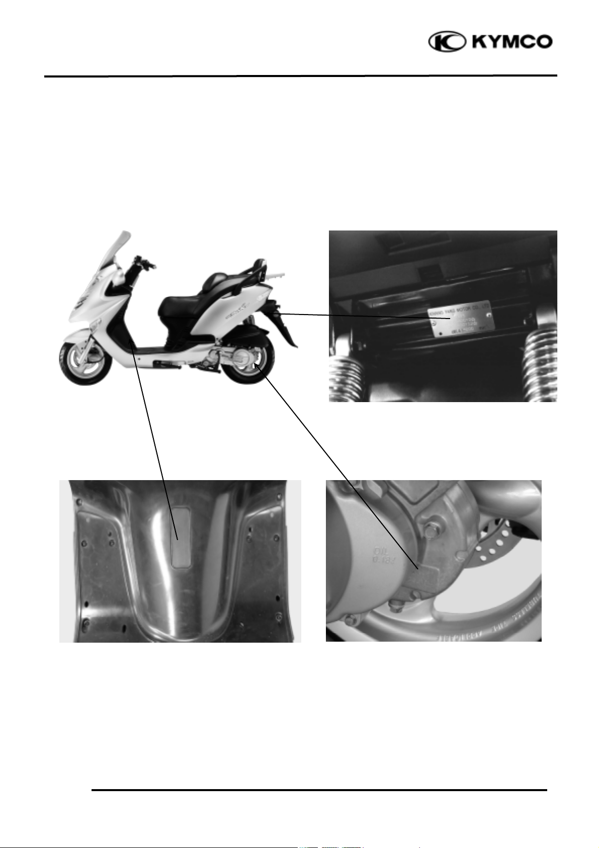
SERIAL NUMBER
Location of Engine Serial Number
Location of Frame Serial Number
Vehicle Identification Serial Number
1. GENERAL INFORMATION
1-2
GRAND DINK 125/15 0
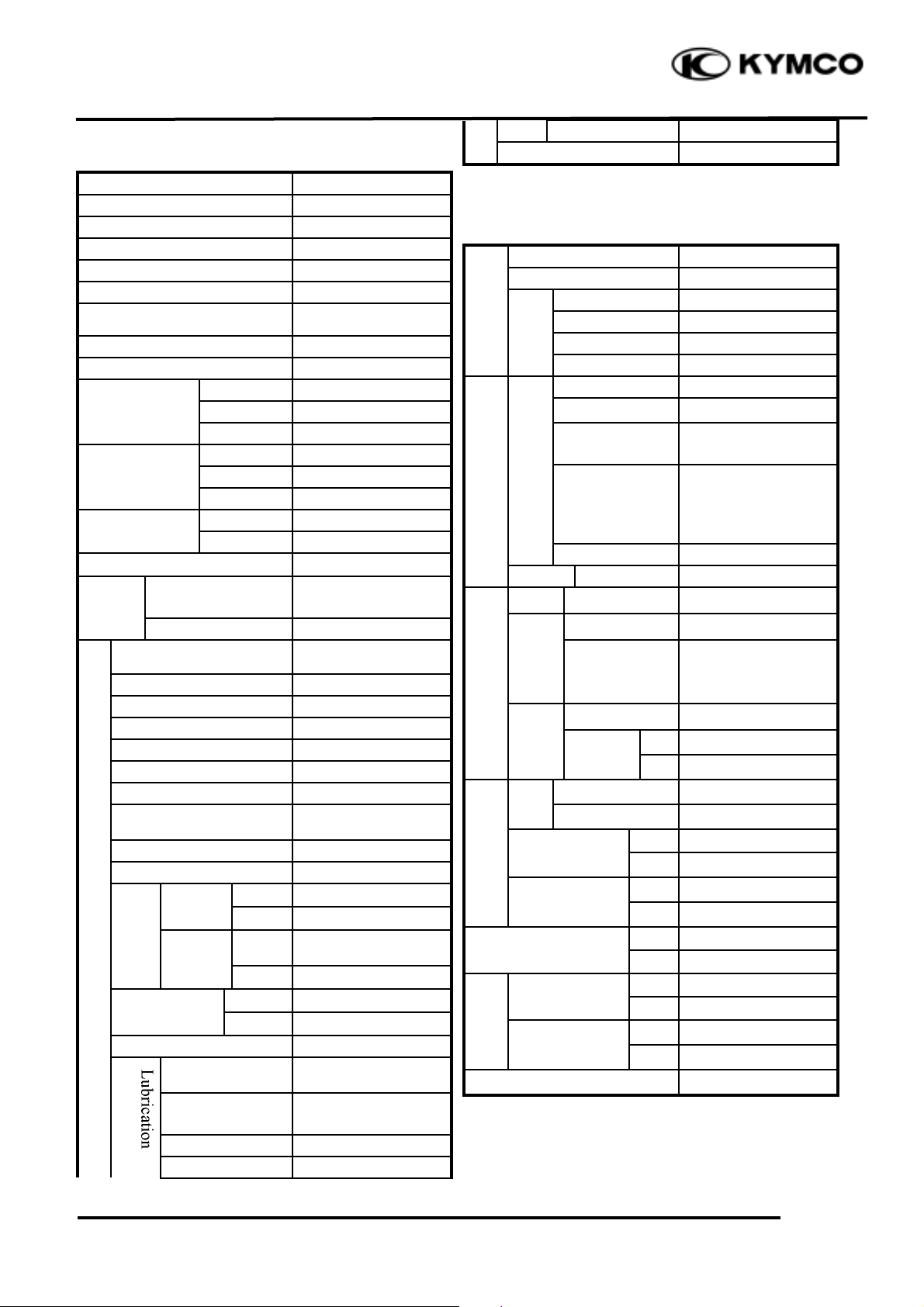
SPECIFICATIONS
Name & Model No.
SH25DA
Motorcycle Name & Type
Overall length
2060mm
Overall width
770mm
Overall height
1360mm
Wheel base
1435mm
Engine type
Water cooled 4-stroke,
OHC engine
Displacement
124.6cc
Fuel Used
92# nonleaded gasoline
Front wheel
58
Net weight (kg)
Rear wheel
82
Total
140
Front wheel
60
Gross weight(kg)
Rear wheel
95
Total
155
Front wheel
120/70-12
Rear wheel
140/70-12
Ground clearance
Perform
-
Braking distance (m)
30km/hr7.0m
ance
Min. turning radius
2350mm
Starting system
Starting motor &
Kick starter
Type
Gasoline, 4-stroke
Cylinder arrangement
Single cylinder
Combustion chamber type
Semi-sphere
Valve arrangement
O.H.C.
Bore x stroke (mm)
52.4 x 57.8
Compression ratio
10:1
Compression pressure
(kg/cm_-rpm)
15
Max. output (kw/rpm)
8.4/7500
Max. torque (N.m/rpm)
9.8/6000
Intake
Open
BTDC 12°
Port
(1mm)
Close
ATDC 35°
timin
g
Exhaust
Open
BDDC 28°
(1mm)
Close
0°
Valve
Intake
0.1mm
clearance (cold)
Exhaust
0.1mm
Idle speed (rpm)
1700rpm
Lubrication type
Forced pressure &
Wet sump
Oil pump type
Inner/outer rotor
type
Oil filter type
Full-flow filtration
Oil capacity
1.1 liters
Cooling Type
Water cooling
Air cleaner type & No
Paper element, wet
Fuel capacity
9.0 liters
Type
VE
Piston dia.
22
Venturi dia.
26 equivalent
Throttle type
Butterfly type
Type
CDI
Ignition timing
10°±1.5°/1000rpm
Contact breaker
Non-contact point
type
Spark plug
NGK
DPR7EA-9
Spark plug gap
0.8~0.9mm
Battery
Capacity
12V8AH
Clutch
Type
Dry multi-disc clutch
Type
Non-stage transmission
Operation
Automatic
centrifugal
Type
Type
Two-stage reduction
Reduction
1st
2.8~1.0
ratio
2nd
8.82
Front
Caster angle
Axle
Connecting rod
Front
1.75
Tire pressure
(kg/cm_)
Rear
2.25
Turning
Left
42.5°
angle
Right
42.5°
Front
Disk brake
Brake system
type
Rear
Disk brake
Front
Telescope
Suspension
type
Rear
Double swing
Shock absorber
Front
Telescope
type
Rear
Double swing
Frame type
Under bone
Tires
Engine
System
Fuel System
Carburetor
Electrical
Ignition System
Power Drive System
Transmis-
sion Gear
Reduction
Gear
Moving Device
Damping
Device
1. GENERAL INFORMATION
1-3
GRAND DINK 125/15 0
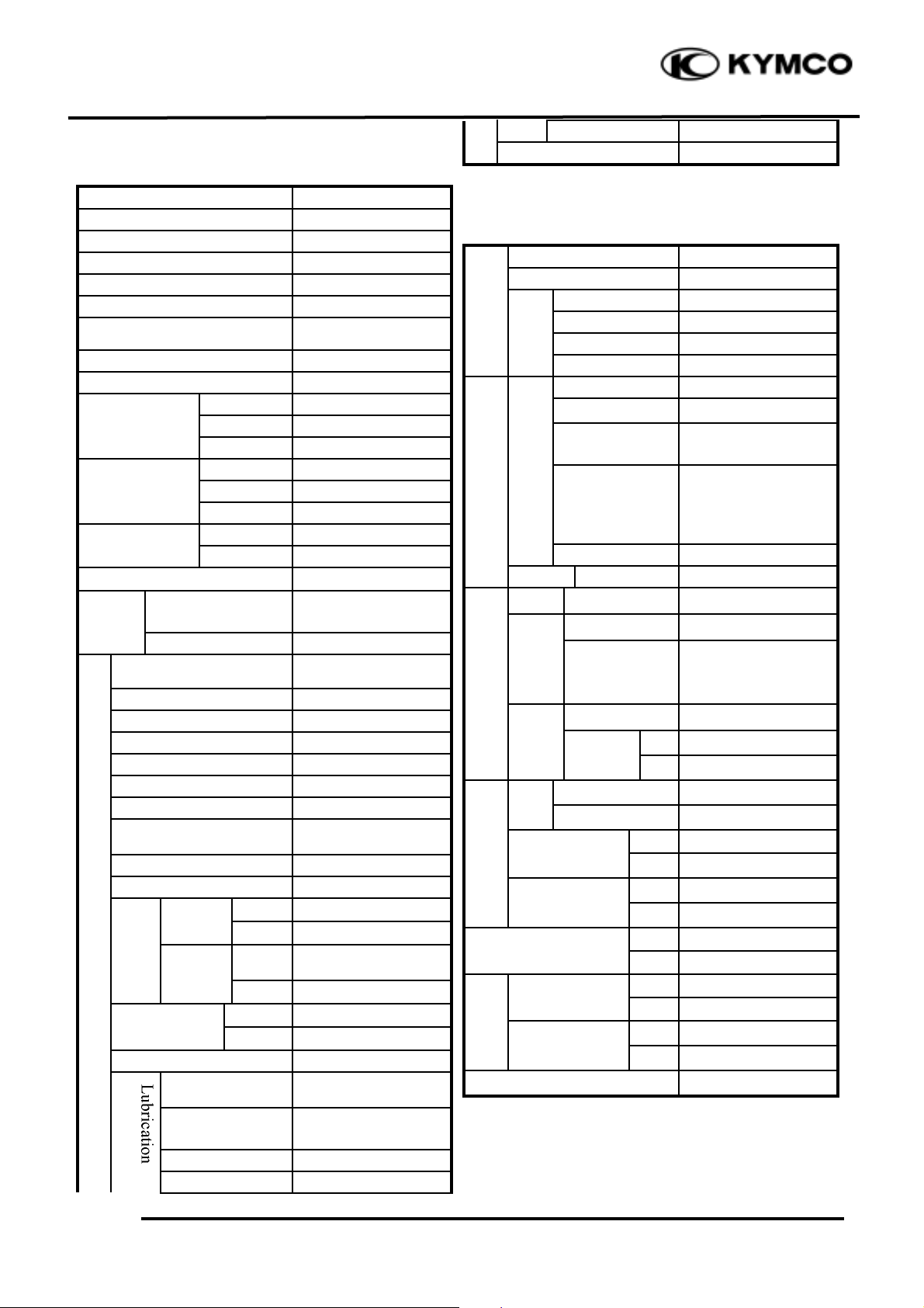
SPECIFICATIONS
Name & Model No.
SH30DA
Motorcycle Name & Type
Overall length
2060mm
Overall width
770mm
Overall height
1360mm
Wheel base
1435mm
Engine type
Water cooled 4-stroke,
OHC engine
Displacement
149.5
Fuel Used
92# nonleaded gasoline
Front wheel
58
Net weight (kg)
Rear wheel
82
Total
140
Front wheel
60
Gross weight(kg)
Rear wheel
95
Total
155
Front wheel
120/70-12
Rear wheel
140/70-12
Ground clearance
Perform
-
Braking distance (m)
30km/hr7.0m
ance
Min. turning radius
2350mm
Starting system
Starting motor &
kick starter
Type
Gasoline, 4-stroke
Cylinder arrangement
Single cylinder
Combustion chamber type
Semi-sphere
Valve arrangement
O.H.C.
Bore x stroke (mm)
57.4 x 57.8
Compression ratio
10.6:1
Compression pressure
(kg/cm_-rpm)
15
Max. output (kw/rpm)
8.8/7500
Max. torque (N.m/rpm)
11.76/6000
Intake
Open
BTDC 12°
Port
(1mm)
Close
ATDC 35°
timin
g
Exhaust
Open
BDDC 28°
(1mm)
Close
0°
Valve
Intake
0.1mm
clearance (cold)
Exhaust
0.1mm
Idle speed (rpm)
1700rpm
Lubrication type
Forced pressure &
wet sump
Oil pump type
Inner/outer rotor
type
Oil filter type
Full-flow filtration
Oil capacity
1.1 liters
Cooling Type
Water cooling
Air cleaner type & No
Paper element, wet
Fuel capacity
9.0 liters
Type
VE
Piston dia.
22
Venturi dia.
26 equivalent
Throttle type
Butterfly type
Type
CDI
Ignition timing
10°±1.5°/1000RPM
Contact breaker
Non-contact point
type
Spark plug
NGK
DP7EA-9
Spark plug gap
0.8~0.9mm
Battery
Capacity
12V8AH
Clutch
Type
Dry multi-disc clutch
Type
Non-stage transmission
Operation
Automatic
centrifugal
Type
Type
Two-stage reduction
Reduction
1st
2.8~1.0
ratio
2nd
8.82
Front
Caster angle
Axle
Connecting rod
Front
2.00
Tire pressure
(kg/cm_)
Rear
2.25
Turning
Left
42.5°
angle
Right
42.5°
Front
Disk brake
Brake system
type
Rear
Disk brake
Front
Telescope
Suspension
type
Rear
Double swing
Shock absorber
Front
Telescope
type
Rear
Double swing
Frame type
Under bone
Tires
Engine
System
Fuel System
Carburetor
Electrical
Ignition System
Power Drive System
Transmis-
sion Gear
Reduction
Gear
Moving Device
Damping
Device
1. GENERAL INFORMATION
1-4
GRAND DINK 125/15 0
SERVICE PRECAUTIONS
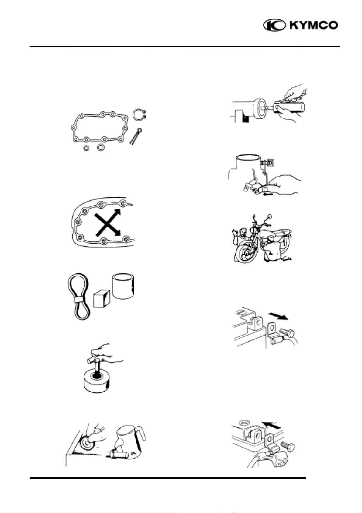
n Make sure to install new gaskets, O-rings,
circlips, cotter pins, etc. when
reassembling.
n When tightening bolts or nuts, begin with
larger-diameter to smaller ones at several
times, and tighten to the specified torque
diagonally.
n Use genuine parts and lubricants.
n When servicing the motorcycle, be sure to
use special tools for removal and
installation.
n After disassembly, clean removed parts.
Lubricate sliding surfaces with engine oil
before reassembly.
n Apply or add designated greases and
lubricants to the specified lubrication
points.
n After reassembly, check all parts for
proper tightening and operation.
n When two persons work together, pay
attention to the mutual working safety.
n Disconnect the battery negative (-) terminal
before operation.
n When using a spanner or other tools, make
sure not to damage the motorcycle surface.
n After operation, check all connecting
points, fasteners, and lines for proper
connection and installation.
n When connecting the battery, the positive
(+) terminal must be connected first.
n After connection, apply grease to the
battery terminals.
n Terminal caps shall be installed securely.
1. GENERAL INFORMATION
1-5
GRAND DINK 125/15 0
n If the fuse is burned out, find the cause and
repair it. Replace it with a new one
according to the specified capacity.
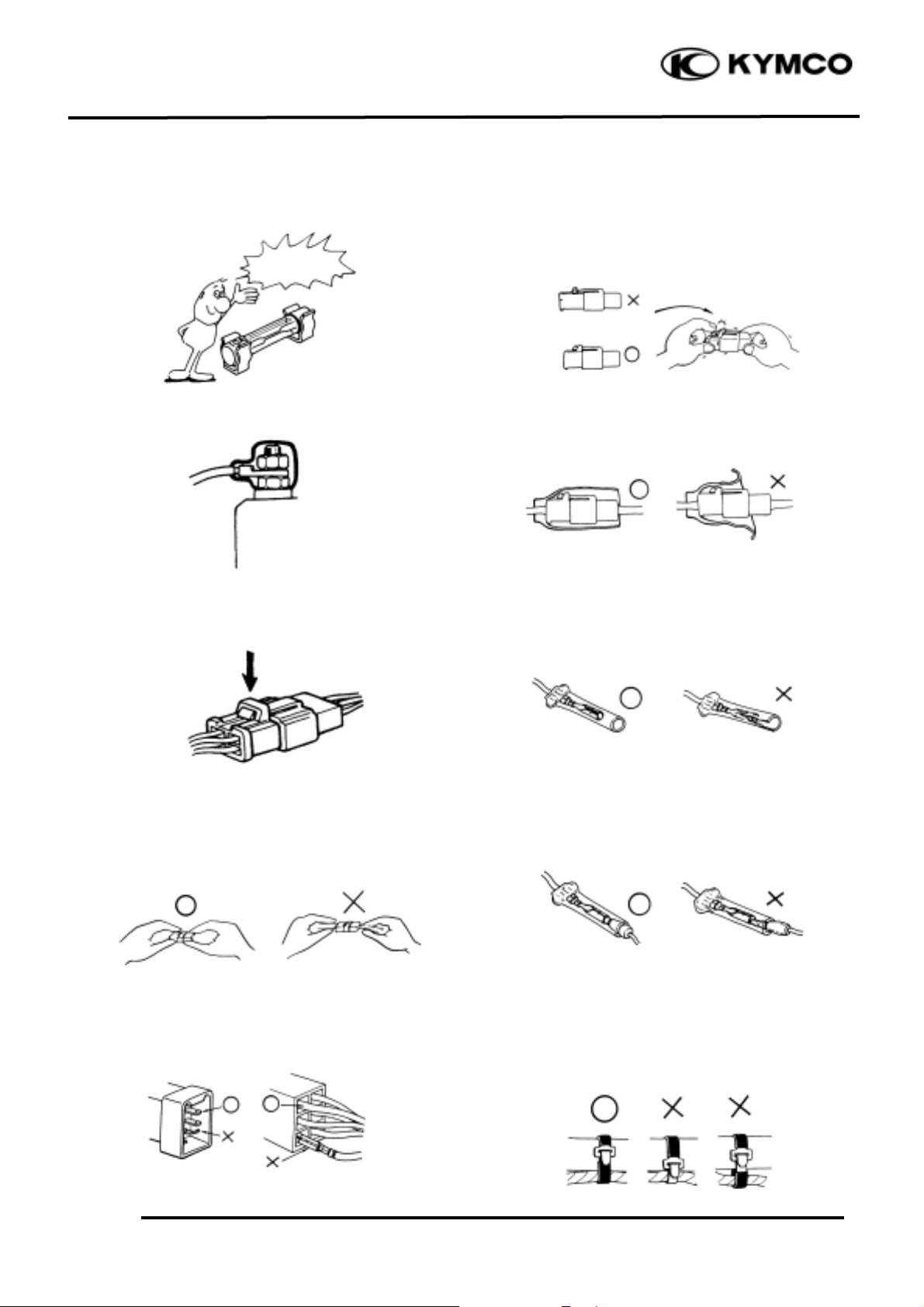
n After operation, terminal caps shall be
installed securely.
n When taking out the connector, the lock on
the connector shall be released before
operation.
n Hold the connector body when connecting
or disconnecting it.
n Do not pull the connector wire.
n Check if any connector terminal is bending,
protruding or loose.
n The connector shall be inserted
completely.
n If the double connector has a lock, lock
it at the correct position.
n Check if there is any loose wire.
n Before connecting a terminal, check for
damaged terminal cover or loose negative
terminal.
n Check the double connector cover for
proper coverage and installation.
n Insert the terminal completely.
n Check the terminal cover for proper
coverage.
n Do not make the terminal cover opening
face up.
n Secure wire harnesses to the frame with
their respective wire bands at the
designated locations.
Tighten the bands so that only the
insulated surfaces contact the wire
harnesses.
Confirm
Capacity

1. GENERAL INFORMATION
1-6
GRAND DINK 125/15 0
n After clamping, check each wire to make
sure it is secure.
n Do not squeeze wires against the weld or
its clamp.
n After clamping, check each harness to make
sure that it is not interfering with any
moving or sliding parts.
n When fixing the wire harnesses, do not
make it contact the parts which will
generate high heat.
n Route wire harnesses to avoid sharp edges
or corners. Avoid the projected ends of
bolts and screws.
n Route wire harnesses passing through the
side of bolts and screws. Avoid the
projected ends of bolts and screws.
n Route harnesses so they are neither
pulled tight nor have excessive slack.
n Protect wires and harnesses with electrical
tape or tube if they contact a sharp edge or
corner.
n When rubber protecting cover is used to
protect the wire harnesses, it shall be
installed securely.
n Do not break the sheath of wire.
n If a wire or harness is with a broken sheath,
repair by wrapping it with protective tape
or replace it.
n When installing other parts, do not press or
squeeze the wires.
Do not pull
too tightð
No Contact
Do not press or squeeze
the wire

1. GENERAL INFORMATION
1-7
GRAND DINK 125/15 0
n After routing, check that the wire harnesses
are not twisted or kinked.
n Wire harnesses routed along with handlebar
should not be pulled tight, have excessive
slack or interfere with adjacent or
surrounding parts in all steering positions.
n When a testing device is used, make sure to
understand the operating methods
thoroughly and operate according to the
operating instructions.
n Be careful not to drop any parts.
n When rust is found on a terminal, remove
the rust with sand paper or equivalent
before connecting.
n Symbols:
The following symbols represent the
servicing methods and cautions included in
this service manual.
: Apply engine oil to the
specified points. (Use
designated engine oil for
lubrication.)
: Apply grease for lubrication.
: Transmission Gear Oil (90#)
: Use special tool.
: Caution
: Warning
Special
Engine Oil
Grease
Gear Oil
*
Do you understand the
instrument?
Remove
Rustð
1. GENERAL INFORMATION
1-8
GRAND DINK 125/15 0
TORQUE VALUES
STANDARD TORQUE VALUES
Item
Torque (N-m)
Item
Torque (N-m)
5mm bolt, nut
6mm bolt, nut
8mm bolt, nut
10mm bolt, nut
12mm bolt, nut
4.9
9.8
21.6
34.3
53.9
5mm screw
6mm screw, SH bolt
6mm flange bolt, nut
8mm flange bolt, nut
10mm flange bolt, nut
3.9
8.8
11.8
26.5
39.2
Torque specifications listed below are for important fasteners.
ENGINE
Item
Q‘ty
Thread dia.(mm)
Torque (N-m)
Remarks
Cylinder head bolt A
Cylinder head bolt B
Oil filter screen cap
Exhaust muffler joint lock nut
Cylinder head cap nut
Valve adjusting lock nut
Cam chain tensioner slipper bolt
Oil bolt
Clutch outer nut
Clutch drive plate nut
Flywheel nut
Oil pump bolt
Cylinder head cover bolt
Spark plug
Cam chain tensioner bolt
Water pump impeller
2
2
1
2
4
2
1
1
1
1
1
2
4
1
1
1
8
8
30
8
8
5
6
12
12
12
14
5
6
10
6
8
21.6
21.6
14.7
8.8
21.6
8.8
8.8
12.7
53.9
53.9
53.9
3.9
11.8
11.8
8.8
13.7
Double end bolt
Double end bolt
Apply oil to
threads
Left hand threads
FRAME
Item
Q‘ty
Thread dia.(mm)
Torque (N-m)
Remarks
Steering stem lock nut
Front axle nut
Rear axle nut
Rear shock absorber upper bolt
Rear shock absorber lower bolt
Front shock absorber lock bolt
Engine hanger bolt
1
1
1
2
2
4
1
10
12
14
10
8
10
12
44.1
58.8
88.2
29.4
29.4
24.5
53.9
U-nut
U-nut
U-nut
1. GENERAL INFORMATION
1-9
GRAND DINK 125/15 0
SPECIAL TOOLS
Tool Name
Tool No.
Remarks
Ref. Page
Valve guide driver
Valve guide removal/installation
Valve guide reamer
Valve guide grinding
Valve spring compressor
Valve removal
Lock nut wrench, 39mm
E027
Clutch disassembly
Bearing driver
Bearing removal
Bearing remover, 12mm
E020
Bearing removal
Remover shaft
Bearing removal
Remover weight
Bearing removal
Bearing remover, 15mm
E018
Bearing removal
Bearing driver
Bearing removal
Clutch spring compressor
E027
Clutch disassembly
Ball race remover extension
Ball race removal
Ball race remover
Ball race removal
Spring compressor
Spring removal
Mechanical seal driver
E014
Water pump mechanical seal
removal/installation
Kick starter spring remover
Kick starter spring removal
Gear remover
Starter gear removal
Valve adjuster
E012
Tapper adjustment
Float level gauge
Carburetor fuel level check
Valve seat cutter 45°
Valve seat refacing
Valve seat cutter 32°
Valve seat refacing
Valve seat cutter 60°
Valve seat refacing
Cutter clip, 5mm
Universal holder
E017
Holding clutch for removal
Bearing driver (32x35mm)
E014
Bearing installation
Pilot, 12mm
E014
Bearing installation
Pilot, 15mm
E014
Bearing installation
Pilot, 17mm
E014
Bearing installation
Flywheel puller
E003
A.C. generator flywheel removal
Rear shock absorber compressor
F004
Rear shock absorber disassembly
Steering head bearing remover
F005
Steering head bearing removal
Flywheel holder
E021
A.C. generator flywheel holding
Reamer clip
Fuel unit wrench
Fuel unit removal
1. GENERAL INFORMATION
1-10
GRAND DINK 125/15 0
LUBRICATION POINTS
ENGINE
Lubrication Points
Lubricant
Valve guide/valve stem movable part
Camshaft protruding surface
Valve rocker arm friction surface
Camshaft drive chain
Cylinder lock bolt and nut
Piston surroundings and piston ring grooves
Piston pin surroundings
Cylinder inside wall
Connecting rod/piston pin hole
Connecting rod big end
Crankshaft
Cranksahft one-way clutch movable part
Oil pump drive chain
Starter reduction gear engaging part
Countershaft gear engaging part
Final gear engaging part
Bearing movable part
O-ring face
Oil seal lip
•Genuine KYM CO Engine Oil (SAE15W-40)
•API SE, SJ Egnine Oil
Starter idle gear
Friction spring movable part/shaft movable part
Shaft movable grooved part
Starter spindle movable part
High-temperature resistant grease
Starter one-way clutch threads
Thread locking agent
A.C. generator connector
Transmission case breather tubee
Adhesive

1. GENERAL INFORMATION
1-11
GRAND DINK 125/15 0
FRAME
The following is the lubrication points for the frame.
Use general purpose grease for parts not listed.
Apply clean engine oil or grease to cables and movable parts not specified. This will avoid
abnormal noise and rise the durability of the motorcycle.
Seat Lock
Rear Wheel Bearing
Grease
Speedometer Cable
Throttle Cable
Speedometer Gear/
Front Wheel Bearing
Engine Oil
Grease
Grease
Grease
Front Brake Lever Pivot
1. GENERAL INFORMATION
1-12
GRAND DINK 125/15 0
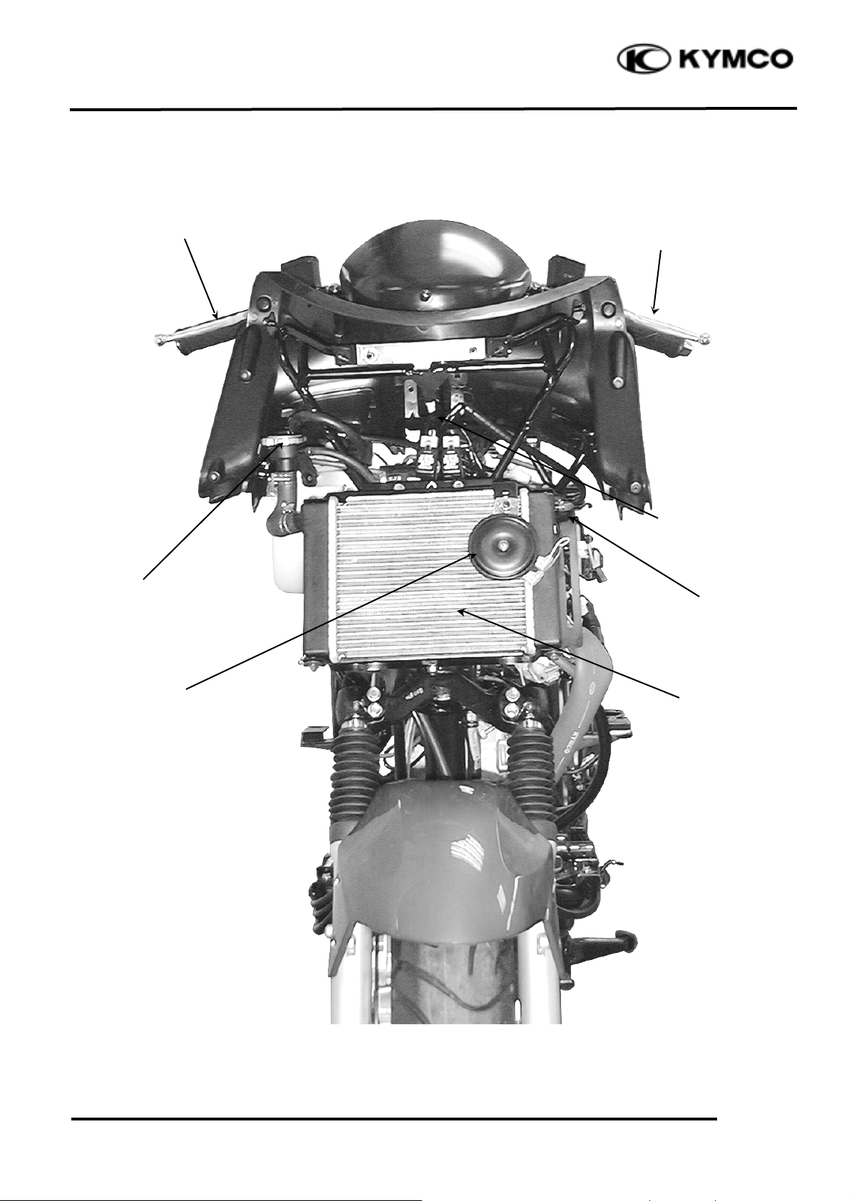
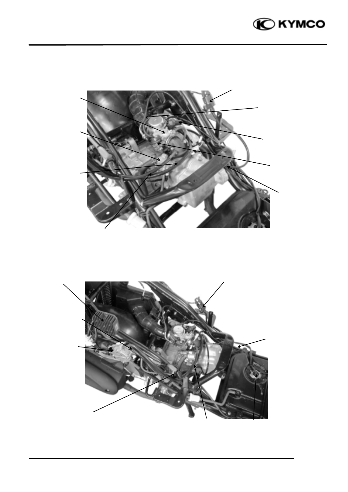
CABLE & HARNESS ROUTING
Radiator
Front Brake
Rear Brake
Speedometer Cable
Horn
Pressure
Type
Radiator Cap
Radiator Air
Vent Tube
1. GENERAL INFORMATION
1-13
GRAND DINK 125/15 0
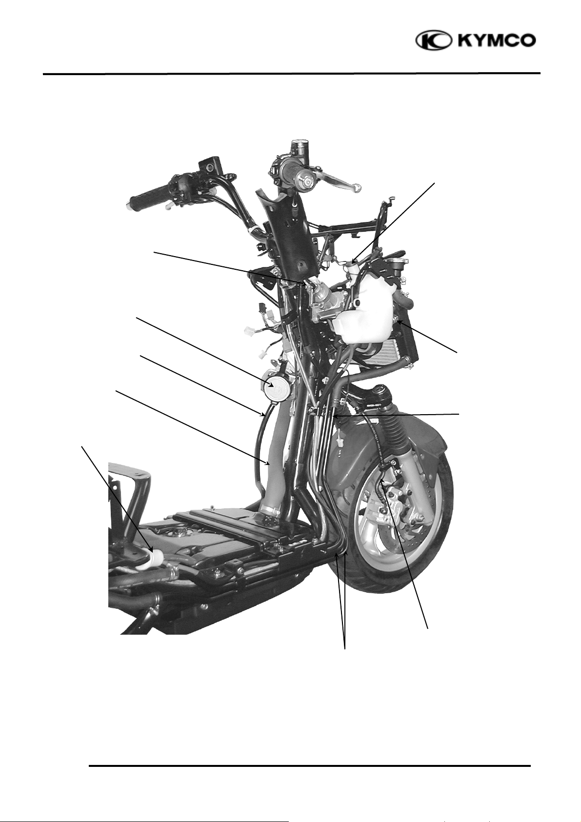
Front Brake Fluid Tube
Fuel Strainer
Fuel Tank
Inlet Tube
Water Hose
Ignition Switch
Fuel Filler
Water Hoses
Thermostatic
Switch
Fuel Tank
Breather Tube
Reserve Tank Cap
1. GENERAL INFORMATION
1-14
GRAND DINK 125/15 0
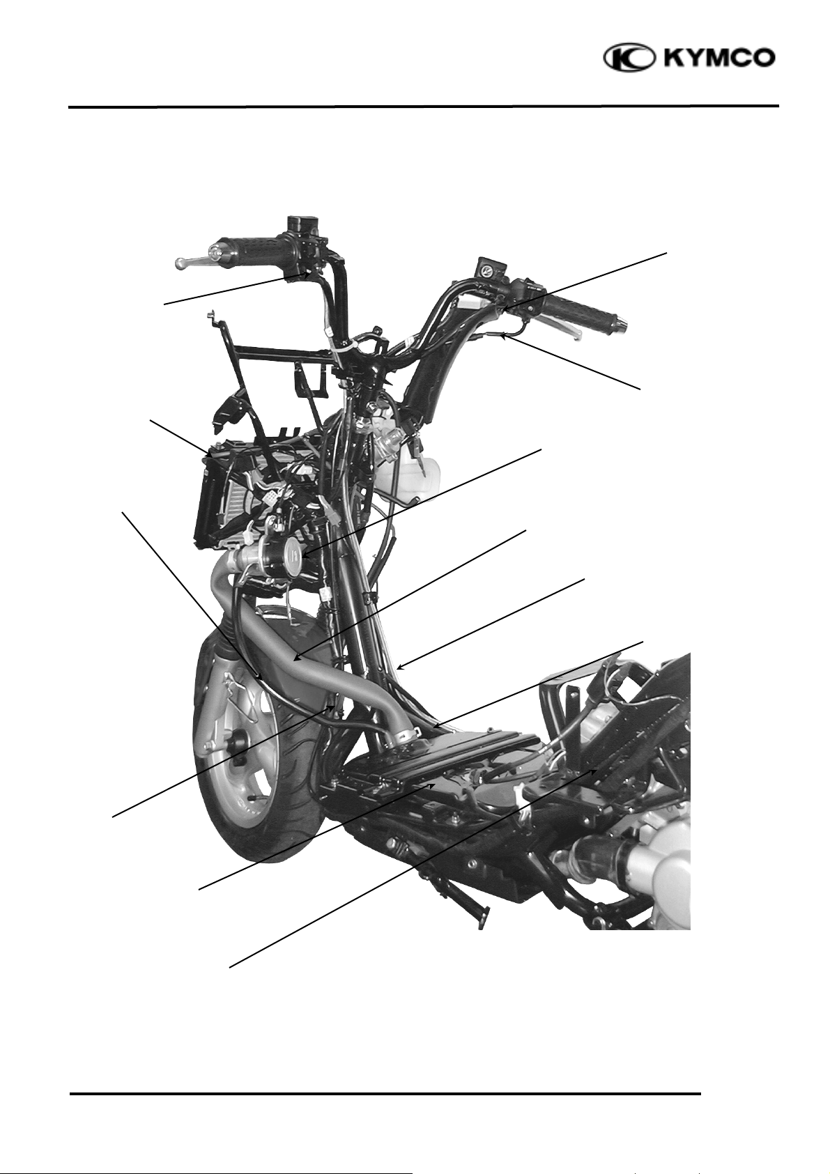
Throttle Cable
Radiator Air
Vent Tube
Rear Brake Fluid
Tube
Fuel Tank Inlet
Tube
Water Hose
Fuel Filler
Fuel Tank
Breather Tube
Throttle Cable
Front Stop
Switch
Wire Harness
Fuel Tank
Rear Stop
Switch
1. GENERAL INFORMATION
1-15
GRAND DINK 125/15 0
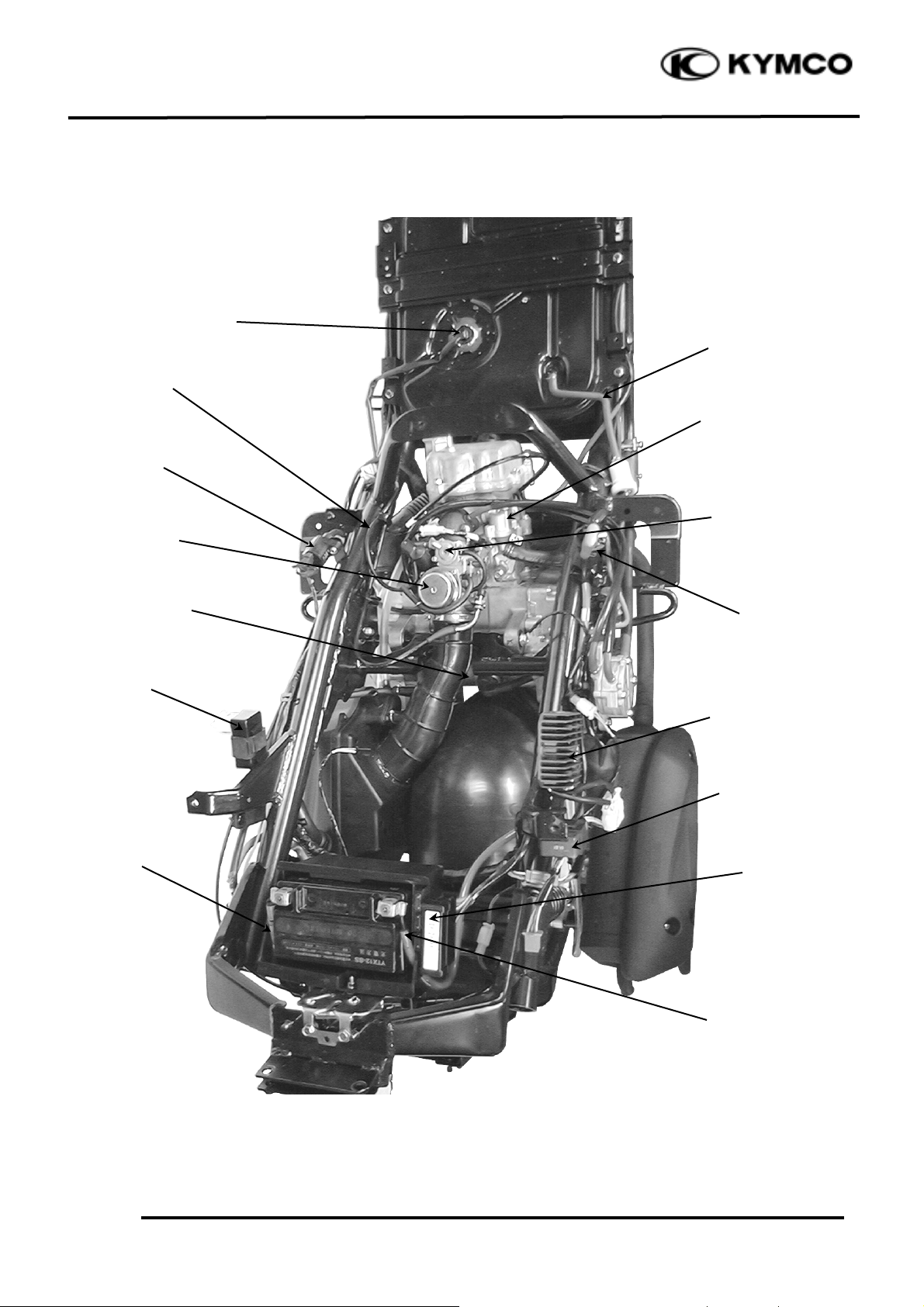
Starter Relay
Fuel Tube
Battery (+) Cable
Battery (-) Cable
Ignition Coil
Auto Bystarter Wire
Thermostat
Carburetor
Air Cut-off
Valve (A.C.V.)
Regulator/
Rectifier
C.D.I.
Fuse Box
Starter Motor
Fuel Unit
Hazard Control
Unit
1. GENERAL INFORMATION
1-16
GRAND DINK 125/15 0
Fuel Tube
Ignition Coil
Thermostat
Air Cut-off
Valve (A.C.V.)
Fuel Tube
Auto Bystarter
Spark Plug
Fuel
Pump
Fuel Unit Wire
Wire Harness
Throttle Cable
Vacuum
Vacuum
Fuel Pump Vacuum Tube
Fuel Pump
Vacuum Tube
Ignition Coil
Starter Relay
Regulator/
Rectifier
1. GENERAL INFORMATION
1-17
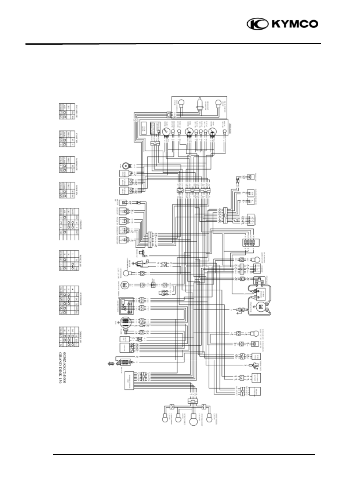
GRAND DINK 125/15 0
WIRING DIAGRAM
1. GENERAL INFORMATION
1-18
GRAND DINK 125/15 0
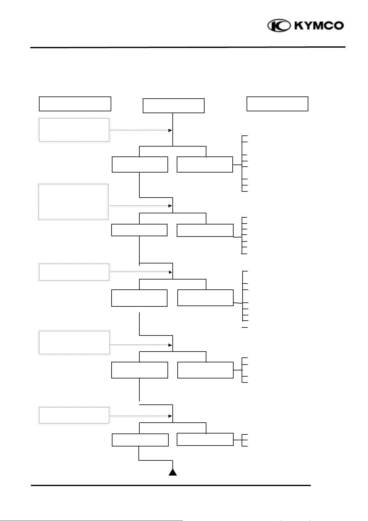
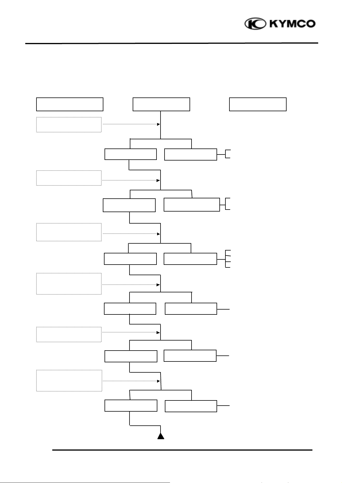
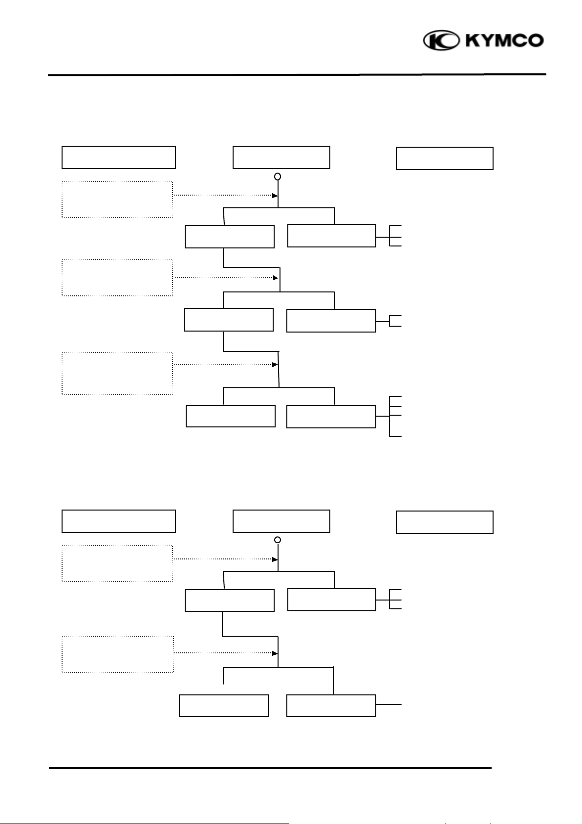
TROUBLESHOOTING
ENGINE WILL NOT START OR IS HARD TO START
ÅEmpty fuel tank
ÇClogged carburetor fuel inlet
tube, vacuum tube or fuel tube
ÉClogged auto fuel valve
ÑClogged float oil passage
ÖClogged fuel tank cap
breather hole
ÜClogged fuel strainer
áClogged fuel filter
àFaulty fuel pump
ÅFaulty spark plug
ÇFouled spark plug
ÉFaulty CDI unit
ÑFaulty A.C. generator
ÖBroken or shorted ignition coil
ÜBroken or shorted exciter
coil
áFaulty ignition switch
ÅStarter motor idles but
crankshaft does not rotate
ÇValve clearance too small
ÉImproper valve and seat
contact
ÑWorn cylinder and piston rings
ÖBlown cylinder head gasket
ÜFlaws in cylinder head
áSeized valve
àImproper valve timing
ÅFaulty auto bystarter
ÇAir leaking through intake
pipe
ÉIncorrect ignition timing
ÑIncorrectly adjusted pilot
screw
ÅFlooded carburetor
ÇFaulty auto bystarter
ÉThrottle valve excessively
open
Check if fuel reaches
carburetor by
loosening drain screw
Remove spark plug
and install it into
spark plug cap to test
spark by connecting it
to engine ground
Inspection/Adjustment
Probable Cause
Spark jumps
Normal
compression
Engine does not
fire
Weak or no spark
Low or no
compression
Engine fires but
does not start
Test cylinder
compression
Start engine by follow-
ing normal starting
procedure
Remove spark plug and
inspect again
Symptom
Fuel reaches
carburetor
Fuel does not
reach carburetor
Wet spark plug
Dry spark plug

1. GENERAL INFORMATION
1-19
GRAND DINK 125/15 0
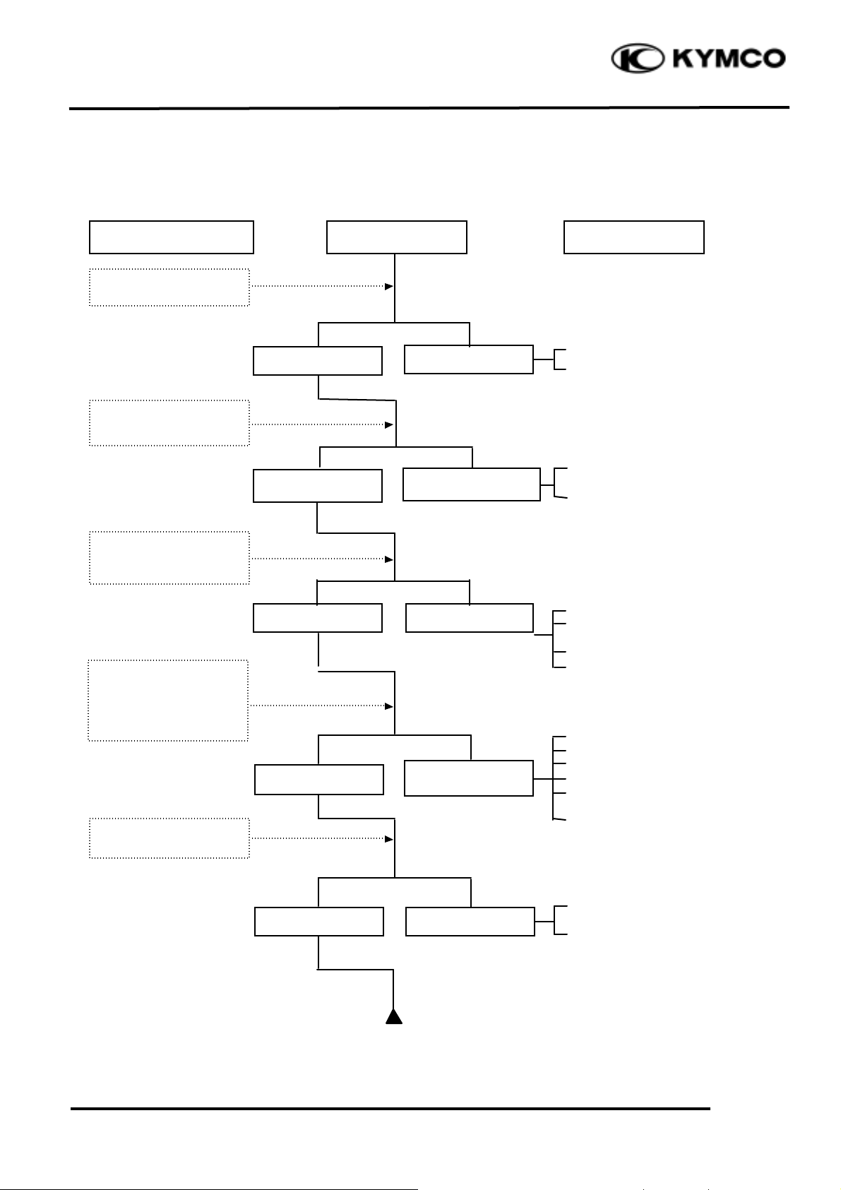
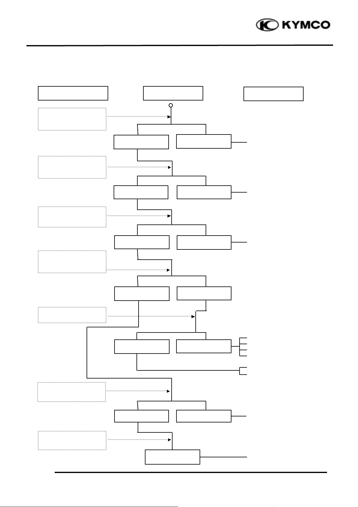
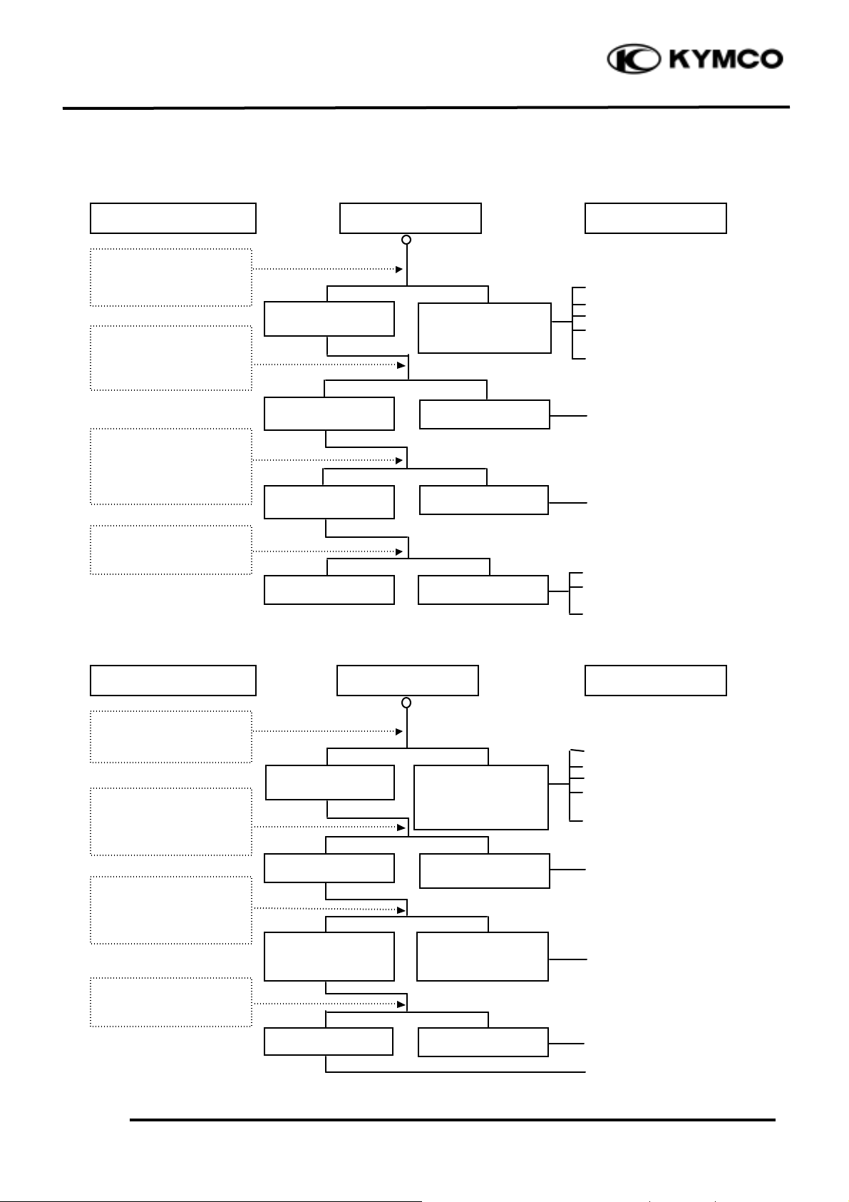
ENGINE LACKS POWER
ÅClogged air cleaner
ÇRestricted fuel flow
ÉClogged fuel line between fuel
tank and carburetor
ÑClogged exhaust muffler
ÖFaulty auto bystarter
ÜSplit carburetor vacuum piston
diaphragm
ÅFaulty CDI unit
ÇFaulty A.C. generator
ÅImproper valve clearance
adjustment
ÇWorn valve seat (valve stem too
protruding
ÅImproper valve and seat contact
ÇWorn cylinder and piston rings
ÉBlown cylinder head gasket
ÑFlaws in cylinder head
ÖImproper valve timing
ÅClogged carburetor jets
ÅFouled spark plug
ÇIncorrect heat range plug
ÅOil level too high
ÇOil level too low
ÉOil not changed
ÅClogged oil pipe
ÇFaulty oil pump
ÅInsufficient coolant
ÇFaulty thermostat
ÉWorn cylinder and piston rings
ÑMixture too lean
ÖPoor quality fuel
ÜExcessive carbon buildup in
combustion chamber
áIgnition timing too early
àAir in cooling system
ÅExcessive carbon build-up in
combustion chamber
ÇPoor quality fuel
ÉClutch slipping
ÑMixture too lean
Ö Ignition timing too early
Start engine and accelerate
lightly for observation
Inspection/Adjustment
Symptom
Probable Cause
Engine speed
increases
Correct timing
Engine speed does
not increase
sufficiently
Incorrect timing
Check ignition timing
(using a timing light)
Test cylinder compression
Check carburetor for
clogging
Rapidly accelerate or run
at high speed
Remove spark plug and
inspect
Check if engine overheats
Check valve clearance
Correct
Incorrect
Normal
compression
Abnormal
compression
Not Clogged
Clogged
Remove oil dipstick and
check oil level and condition
Remove cylinder head oil
pipe bolt and inspect
Engine overheats
Engine does not
overheats
Plug not fouled or
discolored
Plug fouled or
discolored
Correct and not
contaminated
Incorrect or
contaminated
Valve train lubricated
properly
Valve train not
lubricated properly
Engine does not knock
Engine knocks
1. GENERAL INFORMATION
1-20
GRAND DINK 125/15 0
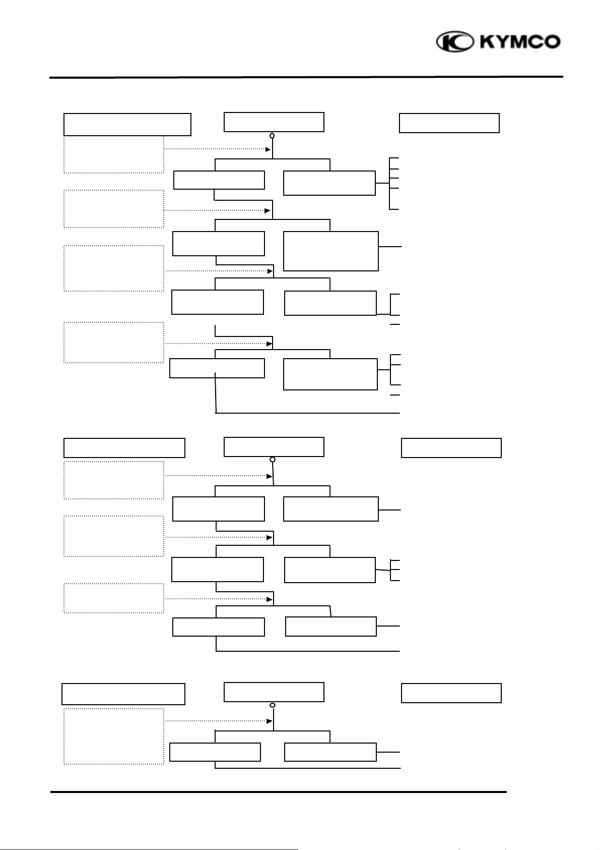
POOR PERFORMANCE (ESPECIALLY AT IDLE AND LOW SPEEDS)
ÅFaulty CDI unit
ÇFaulty A.C. generator
ÅMixture too rich (turn screw
out)
ÇMixture too lean (turn screw
in)
ÅDamaged insulator rubber
ÇCarburetor not securely
tightened
ÉFaulty intake manifold
gasket
ÑDeformed carburetor O-ring
ÅFaulty or fouled spark plug
ÇFaulty CDI unit
ÉFaulty A.C. generator
ÑFaulty ignition coil
ÖBroken or shorted high
tension wire
ÜFaulty ignition switch
ÅDamaged air cut-off valve
diaphragm
ÇDamaged air cut-off valve
spring
Remove spark plug
and install it into
spark plug cap to test
spark by connecting it
to engine ground
Inspection/Adjustment
Symptom
Probable Cause
Check ignition timing
Check carburetor air
cut-off valve
Check carburetor
gasket for air leaks
Check carburetor pilot
screw adjustment
Correct timing
Incorrect timing
Correctly adjusted
No air leak
Air leaks
Good spark
Weak or inter-
mittent spark
Good
Faulty
Incorrectly adjusted
1. GENERAL INFORMATION
1-21
GRAND DINK 125/15 0
POOR PERFORMANCE (AT HIGH SPEED)
ÅFaulty CDI unit
ÇFaulty A.C. generator
ÅImproperly adjusted valve
clearance
ÇWorn valve seat
ÅEmpty fuel tank
ÇClogged fuel tube or filter
ÉFaulty fuel pump
ÑCracked fuel pump vacuum
tube
ÅClean and unclog
ÅCam timing gear aligning
marks not aligned
ÅFaulty spring
Inspection/Adjustment
Symptom
Probable Cause
Check ignition timing
Check carburetor jets
for clogging
Check fuel pump for
fuel supply
Correct timing
Incorrect timing
Check valve spring
tension
Check valve clearance
Fuel flows freely
Fuel flow restricted
Correct
Incorrect
Not clogged
Clogged
Correctly adjusted
Incorrectly adjusted
Not weakened
Weak spring
Check valve timing

1. GENERAL INFORMATION
1-22
GRAND DINK 125/15 0
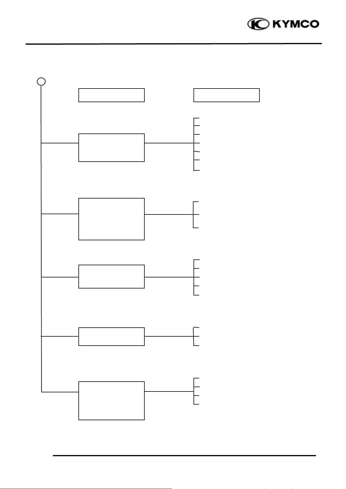
ENGINE NOISE
ÅValve clearance too large
ÇWorn camshaft lobe
ÅWorn piston rings
ÇWorn piston pin and connecting rod
small end
ÉExcessive carbon build-up in combustion
chamber
ÅDamaged cam chain tensioner
ÇWorn cam gear teeth
ÉWorn or damaged cam chain
ÑExtended cam chain
ÅFaulty crankshaft bearing
ÇWorn crank pin bearing
ÅWorn or damaged final reduction gears
ÇWorn final reduction gear shaft splines
Valve noise
Symptom
Probable Cause
Crankshaft noise
Gear noise
Piston noise
Cam chain noise
1. GENERAL INFORMATION
1-23
GRAND DINK 125/15 0
CLUTCH, DRIVE AND DRIVEN PULLEYS
ÅWorn or slipping drive belt
ÇBroken ramp plate
ÉBroken drive face spring
ÑSeparated clutch lining
ÖDamaged driven pulley shaft splines
ÜDamaged final gear
áSeized final gear
ÅBroken shoe spring
ÇClutch outer and clutch weight stuck
ÉSeized pivot
ÅWorn or slipping drive belt
ÇWorn weight rollers
ÉSeized drive pulley bearings
ÑWeak driven face spring
ÖWorn or seized driven pulley bearings
ÅWorn or slipping drive belt
ÇWorn weight rollers
ÉWorn or seized driven pulley bearings
ÅOil or grease fouled drive belt
ÇWorn drive belt
ÉWeak driven face spring
ÑWorn or seized driven pulley bearings
Engine starts but
motor-cycle does not
move
Engine lacks power at
start of a grade(poor
slope performance)
Symptom
Probable Cause
Engine lacks power at
high speed
There is abnormal
noise
or smell while running
Motorcycle creeps or
engine starts but soon
stops or seems to rush
out (Rear wheel
rotates when engine
idles)
1. GENERAL INFORMATION
1-24
GRAND DINK 125/15 0
STARTER MOTOR
1. Starter motor won‘t turn
ÅBurned out fuse
ÇWeak or dead battery
ÉFaulty stop switch
ÑLoose or disconnected
connectors
ÖBroken or shorted ignition
switch wire
ÅFaulty or weak battery
ÅPoor starter button
connection
ÇOpen or shorted starter relay
ÉLoose or disconnected
connectors
ÅWorn brushes
ÇOpen or shorted wires or
rotor
ÉOpen starter motor cable
ÑLoose connectors
ÅOpen wire harness
2. Starter motor turns slowly or idles
ÅWeak or dead battery
ÅLoose connector or terminal
ÇPoor contact in starter relay
ÉFaulty starter clutch
ÅSeized cylinder
ÅBroken or shorted starter
motor cable
3. Starter motor does not stop turning
ÅFaulty starter pinion
ÅStarter relay shorted or stuck
Inspection/Adjustment
Inspection/Adjustment
Inspection/Adjustment
Symptom
Symptom
Symptom
Check operation of
stop switch by
applying brake
Stoplight does not
come on
Stoplight comes
Check bat t ery
circuit by operating
turn signals
Check battery
circuit by operating
turn signals
Turn ignition
switch
OFF
Probable Cause
Probable Cause
Probable Cause
Signals operate
properly
Signals dim, remain
on or don‘t
operate
Check operation of
starter relay by
depressing starter
button
Connect starter
motor directly to
battery
Connect starter
motor directly to
battery
Starter motor
turns slowly
Starter motor
turns normally
Signals operate
properly
Signals dim, remain
on or don‘t operate
Not stopped
Stopped
Rotate crankshaft
Starter motor
Starter does not
turn
Relay operates
properly
Relay does not
operate
Turns easily
Hard to turn
1. GENERAL INFORMATION
1-25
GRAND DINK 125/15 0
closed
NO SPARK AT SPARK PLUG
ÅFaulty spark plug
ÅFaulty spark plug
ÅPoorly connected coupler
ÅFaulty ignition switch
ÇFaulty exciter coil
ÉFaulty pulser coil
ÑFaulty ignition coil
ÅBroken wire harness
ÇPoorly connected coupler
ÅFaulty CDI unit
ÅFaulty ignition coil
Replace with a new
spark plug and inspect
again
Check CDI unit
coupler for looseness
Inspection/Adjustment
Symptom
Probable Cause
Normal
Abnormal
Normal
Abnormal
Normal
Abnormal
Abnormal
Measure resistance
between terminals of
CDI unit coupler
Check related parts
Check ignition coil
with a CDI unit tester
Weak or no spark
Not loose
Good spark
Loose
Good
Good
Check spark plug cap
and high-tension wire
for looseness
Check CDI unit with a
CDI unit tester
1. GENERAL INFORMATION
1-26
GRAND DINK 125/15 0
POOR CHARGING (BATTERY OVER DISCHARGING OR OVERCHARGING)
Undercharging
ÅFaulty AC generator
ÇFaulty regulator/rectifier
ÉFaulty battery
ÅShorted AC generator coil
ÇOpen circuit between AC
generator 3 yellow wires
ÅFaulty regulator/rectifier
ÇFaulty AC generator
ÉLoose regulator/rectifier
coupler
ÑLimit voltage too high
Overcharging
ÅFaulty battery
ÇFaulty regulator/rectifier
ÉBroken or poorly
connected
regulator/rect ifier black wire
ÅLimit voltage too high
Start engine and test
limit voltage of
battery terminals
Measure battery limit
voltage with an
electric tester
Test output voltage of
regulator/rectifier
coupler red wire
Inspection/Adjustment
Inspection/Adjustment
Symptom
Symptom
Probable Cause
Probable Cause
Normal voltage
Normal
Normal
Voltage does not
increase
Abnormal
Resistance too
Normal voltage
No voltage
Measure resistance
between AC generator
coil terminals
Check resistance
between regulator/
rectifier terminals
Normal
Abnormal
1. GENERAL INFORMATION
1-27
GRAND DINK 125/15 0
FUEL GAUGE
1. Pointer does not register correctly (Ignition switch ON)
ÅBurned out fuse
ÇWeak or dead battery
ÉFaulty ignition switch
ÑLoose or disconnected
connectors
ÖBroken wire harness
ÅFaulty float
ÅBroken or shorted fuel
unit wire
ÅDisconnected connector
ÇIncorrectly connected
connector
ÉBroken or shorted wire in
fuel gauge
2. Pointer fluctuates or swings (Ignition switch ON)
ÅBurned out fuse
ÇWeak or dead battery
ÉFaulty ignition switch
ÑLoose or disconnected
connector
ÖBroken wire harness
ÅPoor contact in fuel unit
ÅInsufficient damping oil in
fuel gauge
ÅLoose or disconnected
connector
ÅBroken or shorted wire in
fuel gauge
Inspection/Adjustment
Inspection/Adjustment
Symptom
Symptom
Remove fuel unit and
check operation of
pointer by moving
float up and down
Remove fuel unit and
check operation of
pointer by moving
float up and down
Signals operate
properly
Signals dim, remain
on or don‘t
operate
Signals operate
properly
Signals dim,
remain
on or don‘t
operate
Check battery circuit
by operating turn
signals
Check battery circuit
by operating turn
signals and horn
Probable Cause
Probable Cause
Pointer does not
move
Pointer moves
Pointer moves
Pointer does not
move
Check operation of
pointer by opening and
shorting fuel unit
terminal on wire
harness side
Move float up and
down rapidly (1 round
/sec.) to check the
operation of pointer
Pointer does not
move
Pointer moves
Pointer does not
move in accord-
ance with float
Pointer moves in
accordance with
float
Good
Faulty
Check connectors for
proper connection
Check connectors for
proper connection.
Good
Faulty
Float up: Full
Float down: Empty

1. GENERAL INFORMATION
1-28
GRAND DINK 125/15 0
STEERING HANDLEBAR DOES NOT TRACK STRAIGHT
(Front and rear tire pressures are normal)
ÅSteering stem nut too tight
ÇBroken steering steel balls
ÅExcessive wheel bearing play
ÇBent rim
ÉLoose axle nut
ÅMisaligned front and rear wheels
ÇBent front fork
POOR SUSPENSION PERFORMANCE
(Front and rear tire pressures are normal)
ÅWeak shock spring
ÇExcessive load
ÉShock damper oil leaking
ÅBent fork tube or shock rod
ÅFork tube and slider binding
ÇFork spring and slider binding
ÉDamaged shock stopper rubber
ÑLoose steering stem nut
POOR BRAKE PERFORMANCE
ÅWorn brake linings
ÇForeign matter on brake linings
ÉRough brake drum contacting area
ÅWorn brake linings
ÇForeign matter on brake linings
ÉRough brake drum contacting area
ÅWorn brake linings
ÇWorn brake cam contacting area on
ÅWorn brake linings
ÇForeign matter on brake linings
ÅSluggish or elongated brake cables
ÇBrake shoes improperly contact
ÉWater and mud in brake system
ÑOil or grease on brake linings
Steering is heavy
Suspension is too soft
Soft brake lever
Hard brake lever
Poor brake
performance
Front or rear wheel is
wobbling
Symptom
Symptom
Symptom
Probable Cause
Probable Cause
Probable Cause
Steering handlebar pulls
to one side
Suspension is too hard
Suspension is noisy
Brake squeaks
Hard to brake
 Loading...