


MXU 500 / MXU 500 IRS
ATV off road
Do not remove this Owner’s Manual from the vehicle. Read this manual carefully before operating the vehicle as it contains important safety information.
Owner’s Manual
C 2008 KYMCO. All rights reserved. Printed in Taiwan. www.kymco.com |
Version:T200-LAAOCA-US-A5 |
IMPORTANT NOTICES
READ THIS MANUAL CAREFULLY
Your Owner's Manual contains important information on safety, operation, and maintenance. Any one who operates this ATV should carefully read and understand the contents of this manual before riding the vehicle.
AGE RECOMMENDATION
The minimum recommended age for this ATV model is 16. Children under age 16 should never operate this vehicle.
RIDER TRAINING
Anyone who operates this vehicle should get proper instruction.
FOR OFF-ROAD USE ONLY
This vehicle is designed and manufactured for off-road use only. This machine is designed and manufactured for OFF-ROAD use only. It is illegal and unsafe to operate this machine on any public street, road or highway.
This machine complies with all applicable OFF-ROAD noise level and spark arrester laws and regulation in effect at the time of manufacture.
Please check your local riding laws and regulations before operating this machine.
A

SPECIAL MESSAGES
KYMCO provides many important safety messages both in this manual and on the vehicle. For your safety and the safety of others, pay special attention to all warnings preceded by this alert symbol  . Failure to follow the warnings contained in this manual can result in SERIOUS INJURY or DEATH.

 WARNING
CAUTION
Note:
Indicates a strong possibility that serious injury or death may result if instructions are not followed.
Indicates a possibility that equipment or property damage could result if instructions are not followed.
Gives helpful information
The Owner's Manual should be considered a permanent part of your ATV. It should remain with the vehicle at all times and stay with the ATV if it is sold.
B

PREFACE
Congratulations on your purchase of the KYMCO ATV. KYMCO take pride in a worldwide reputation for quality-in research, design, production and service.
For replacement parts and accessories, we recommend genuine KYMCO products. They've been specially designed for your vehicle and manufactured to meet KYMCO's demanding standards.
This manual will provide you with a good basic understanding of the features and operation of this machine. This manual includes important safety information. It provides information about special techniques and skills necessary to ride your machine. It also includes basic maintenance and inspection procedures. If you have any questions regarding the operation or maintenance of your machine, please consult a KYMCO dealer.
We wish you many years of safe and enjoyable riding.
While reading this manual, remember:
Indicates a strong possibility that serious injury or death may
WARNING
result if instructions are not followed.
All information in this publication is based on the latest product information available at the time of approval for printing. KWANG YANG MOTOR CO.,LTD Reserves the right to make changes at any time without notice and without incurring any obligation.
C
|
CONTENTS |
|
Page |
LOCATION OF THE WARNING AND |
|
SPECIFICATION LABELS |
...................1 |
SAFETY INFORMATION...................... |
4 |
DESCRIPTION AND MACHINE |
|
IDENTIFICATION.................................. |
9 |
IDENTIFICATION NUMBER |
|
RECORDS........................................... |
9 |
KEY IDENTIFICATION NUMBER............ |
9 |
FRAME SERIAL NUMBER................... |
10 |
ENGINE SERIAL NUMBER.................. |
10 |
PARTS LOCATION............................. |
11 |
D
|
Page |
FRONT BRAKE LEVER....................... |
32 |
REAR BRAKE LEVER.......................... |
32 |
BRAKE PEDAL................................... |
32 |
PARKING BRAKE............................... |
33 |
DRIVE SELECT LEVER....................... |
34 |
FUEL TANK CAP ................................ |
35 |
FUEL VALVE...................................... |
35 |
CHOKE KNOB.................................... |
37 |
ACCELERATING PUMP LEVER ......... |
38 |
SEAT.................................................. |
39 |
FLAG POLE BRACKET....................... |
40 |
TRAILER HITCH................................. |
40 |
OWNER’S MANUAL STORAGE |
|
COMPARTMENT................................. |
41 |
ACCESSORY SOCKET........................ |
42 |
|
Page |
PRE-OPERATION CHECKS.............43 |
|
DRIVE SELECT LEVER ...................... |
44 |
Drive select lever adjustment............ |
46 |
FRONT AND REAR BRAKES................ |
48 |
FUEL............................................... |
49 |
DRIVE SHAFT BOOTS........................ |
50 |
ENGINE OIL ...................................... |
51 |
FINAL GEAR OIL................................ |
52 |
DIFFERENTIAL GEAR OIL.................. |
52 |
THROTTLE LEVER............................. |
53 |
FITTINGS AND FASTENERS............... |
53 |
LIGHTS.............................................. |
53 |
SWITCHES......................................... |
53 |
TIRES................................................ |
54 |
How to measure tire pressure .............. |
55 |
Tire wear limit .................................... |
56 |
COOLANT.......................................... |
56 |
|
(Cont'd) |
E
|
Page |
OPERATION........................................ |
58 |
STARTING A COLD ENGINE............... |
58 |
Using the recoil starter...................... |
61 |
STARTING A WARM ENGINE.............. |
62 |
WARMING UP..................................... |
62 |
DRIVE SELECT LEVER OPERATION |
|
AND REVERSE DRIVING .................... |
63 |
Shifting: neutral to high |
|
and high to low ................................. |
63 |
Shifting: neutral to reverse |
|
and reverse to park........................... |
64 |
ENGINE BREAK-IN............................. |
65 |
PARKING.......................................... |
66 |
Parking on a slope............................ |
67 |
ACCESSORIES .................................. |
68 |
LOADING ........................................... |
69 |
Page |
|
RIDING YOUR ATV ............................ |
71 |
GETTING TO KNOW YOUR ATV ......... |
72 |
RIDE WITH CARE AND GOOD |
|
JUDGEMENT...................................... |
73 |
APPAREL........................................... |
75 |
PRE-OPERATION CHECKS................ |
79 |
Speed limiter................................... |
80 |
LOADING AND ACCESSORIES.......... |
81 |
Load Limits...................................... |
81 |
Loading and operational guidelines... |
81 |
Accessories..................................... |
82 |
MODIFICATIONS................................ |
83 |
No modifications.............................. |
83 |
EXHAUST SYSTEM............................ |
84 |
BE CAREFUL WHERE YOU RIDE........ |
85 |
FOR OFF-ROAD USE ONLY................. |
90 |
DURING OPERATION......................... |
92 |
TURNING YOUR ATV .......................... |
94 |
SLIDING AND SKIDDING.................... |
96 |
CLIMBING UPHILL............................. |
98 |
(Cont'd)
F
|
Page |
RIDING DOWNHILL....................... |
104 |
CROSSING A SLOPE......................... |
106 |
RIDING OVER ROUGH TERRAIN....... |
108 |
CROSSING THROUGH SHALLOW |
|
WATER...................................... |
..109 |
PA R K I N G . . . . . . . . . . . . . . . . . . . . . . . . . . . . . . . . . . |
. . 11 0 |
WHAT TO DO IF.................................. |
111 |
WHAT TO DO.................................... |
111 |
|
Page |
PERIODIC MAINTENANCE AND |
|
ADJUSTMENT................................... |
113 |
TOOL KIT/ |
|
TOOL KIT COMPARTMENT................. |
113 |
PERIODIC MAINTENANCE/ |
|
LUBRICATION.................................. |
115 |
ENGINE OIL...................................... |
118 |
FINAL GEAR OIL............................... |
125 |
DIFFERENTIAL GEAR OIL................. |
127 |
SPARK PLUG INSPECTION.............. |
129 |
SPARK ARRESTER........................... |
130 |
AIR FILTER CLEANING..................... |
132 |
AIR CLEANER HOUSING DRAIN |
|
TUBE............................................... |
135 |
IDLE SPEED ADJUSTMENT ............. |
136 |
THROTTLE LEVER ADJUSTMENT.... |
137 |
VALVE CLEARANCE ADJUSTMENT..138 |
|
FRONT BRAKE PADS INSPECTION... |
138 |
REAR BRAKE PADS INSPECTION..... |
139 |
BRAKE FLUID INSPECTION.............. |
139 |
(cont'd) |
|
G
|
Page |
|
Page |
COOLING SYSTEM INSPECTION...... |
141 |
CLEANING AND STORAGE |
...........153 |
Engine overheating........................ |
143 |
A. CLEANING |
153 |
|
|
||
WHEEL REMOVAL............................ |
144 |
B. STORAGE |
155 |
|
|
||
WHEEL INSTALLATION..................... |
144 |
|
|
BATTERY.......................................... |
146 |
SPECIFICATIONS |
157 |
|
|
||
Battery remove.............................. |
147 |
|
|
Battery installation......................... |
147 |
NOISE REGULATION............................. |
161 |
FUSE REPLACEMENT...................... |
148 |
|
|
HEADLIGHT BEAM ADJUSTMENT |
149 |
MAINTENANCE RECORD....................... |
162 |
|
|
||
DRIVE SHAFT BOOTS....................... |
149 |
INDEX |
163 |
CABLE INSPECTION AND |
|
||
|
|
|
|
LUBRICATION.................................. |
150 |
|
|
TROUBLESHOOTING ....................... |
151 |
|
|
Troubleshooting chart................... |
152 |
|
|
H

LOCATION OF THE WARNING AND
SPECIFICATION LABELS
WARNING INFORMATION
Anyone who rides the vehicle should read and understand this information before riding. They contain important information for safe and proper operation of your ATV.
The labels should be considered as permanent parts of the vehicle. If a label comes off or becomes hard to read, contact your KYMCO dealer for replacements.
(A) (US version only)
(1) |
(2) |
(3) |
(4) |
(5) |
/ MXU 500 IRS
(B) (US version only)
|
|
|
|
|
|
(B) (7) (A) (6)-a or (6)-b |
(8) |
||||
1
(1)
WARNING
Never carry passenger on
This carrier.
Maximum load 45 Kg (100 lbs)
(2)
WARNING
NEVER ride as a passenger.
Passengers can cause a loss of control, resulting in SEVERE INJURY or DEATH.
(4)
CAUTION
Before shifting, you must stop the machine and return the throttle lever to its closed position until the engine speed to the specified idling speed.
Otherwise, the transmission may be damaged.
(3)
(5)
WARNING
Never carry passenger on
This carrier.
Maximum load 85 Kg (187 lbs)
(6)-a(MXU 500)
2

(6)-b(MXU 500 IRS) |
(7) |
|
Improper tire pressure or overloading can cause loss of control.
Loss of control can result in severe injur y or death.
Cold tire pressure:
Front: 5.0 psi (35 kPa) Rear: 4.5 psi (32 kPa)
Maximum weight capacity: 485 lbs
|
(220 kg) |
|
|
87505-LFE9-M35 |
|
(8) |
|
|
WARNING |
||
|
|
Exceeding vehicle towing limit could lead to an accident. Reduce speed when towing a trailer. Read owner's manual for details.
MAXIMUM TOWING CAPACITY: 454kg (1000lbs)
TONGUE WEIGHT: 16kg (35 lbs)

SAFETY INFORMATION
AN ATV IS NOT A TOY AND CAN BE HAZARDOUS TO OPERATE. An ATV handles differently from other vehicles including motorcycles and cars. An accident can occur quickly, even during routine maneuvers such as turning and riding on hills or over obstacles, if you fail to take proper precautions.
SEVERE INJURY OR DEATH can result if you do not follow these instructions:
Read this manual and all labels carefully and follow the operating procedures described.
Never operate an ATV without proper training or instruction. Beginners should receive training from a certified instructor.
Always follow the age recommendation:
- A child under 16 years old should never operate an ATV with engine size greater than 90cc.
Never carry a passenger on an ATV.
Always avoid operating an ATV on any paved surfaces, including sidewalks, driveways, parking lots and streets.
Never operate an ATV on any public street, road or highway, even a dirt or gravel one.
4
Never operate an ATV without wearing an approved motorcycle helmet that fits properly. You should also wear eye protection (goggles or face shield), gloves, boots, long-sleeved shirt or jacket, and long pants.
Never consume alcohol or drugs before or while operating this ATV.
Never operate at speeds too fast for your skills or the conditions. Always go at a speed that is proper for the terrain, visibility and operating conditions, and your experience.
Never attempt wheel, jump, or other stunt.
Always inspect your ATV each time you use it to make sure it is in safe operating condition. Always follow the inspection and maintenance procedures and schedules described in this manual.
Always keep both hands on the handlebars and both feet on the footboards of the ATV during operation.
Always follow proper procedures for turning as described in this manual. Practice turning at low speeds before attempting to turn at faster speeds. Do not turn at excessive speed.
Never operate on excessively rough, slippery or loose terrain until you have learned and practiced the skills necessary to control the ATV on such terrain. Always be especially cautious on these kinds of terrain.
Always go slowly and be extra careful when operating on unfamiliar terrain. Always be alert to changing terrain conditions when operating the ATV.
5
Always follow proper procedures for climbing hills as described in this manual. Check the terrain carefully before you start up any hill. Never climb hills with excessively slippery or loose surfaces. Shift your weight forward. Never open the throttle suddenly. Never go over the top of a hill at high speed.
Always follow proper procedures for going down hills and for braking on hills as described in this manual. Check the terrain carefully before you start down any hill. Shift your weight backward. Never go down a hill at high speed. Avoid going down hill at an angle that would cause the vehicle to lean sharply to one side. Go straight down the hill where possible.
Always follow proper procedures for crossing the side of a hill as described in this manual. Avoid hills with excessively slippery or loose surfaces. Shift your weight to the uphill side of the ATV. Never attempt to turn the ATV around on any hill until you have mastered the turning technique described in this manual on level ground. Avoid crossing the side of a steep hill if possible.
Never operate the ATV on hills too steep. Practice on smaller hills before attempting larger hills.
Always use proper procedures if you stall or roll backwards when climbing a hill. To avoid stalling, maintain a steady speed when climbing a hill. If you stall or roll backwards, follow the special procedure for braking described in this manual. Dismount on the uphill side or to a side if pointed straight uphill. Turn the ATV around and remount, following the procedure described in this manual.
6

WARNING
POTENTIAL HAZARD
Improper handling of gasoline.
WHAT CAN HAPPEN
Gasoline can catch fire and you could be burned.
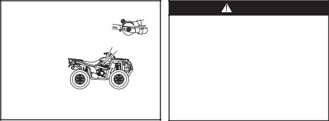
HOW TO AVOID THE HAZARD
Always turn off the engine when refueling. Do not refuel right after the engine has been running and is still very hot.
Do not spill gasoline on the engine or exhaust pipe/muffler when refueling.
Never refuel while smoking, or while in the vicinity of sparks, open flames, or other sources of ignition such as the pilot lights of water heaters and clothes dryers.
When transporting the machine in another vehicle, be sure it is kept upright and that the fuel cock is in the "OFF" position.
Otherwise, fuel may leak out of the carburetor or fuel tank.
WHAT CAN HAPPEN
Gasoline is poisonous and can cause injuries.
HOW TO AVOID THE HAZARD
If you should swallow some gasoline or inhale a lot of gasoline vapor, or get some gasoline in your eyes, see your doctor immediately.
If gasoline spills on your skin, wash with soap and water. If gasoline spills on your clothing, change your clothes.
7
ON
WARNING
POTENTIAL HAZARD
Starting or running the engine in a closed area.
WHAT CAN HAPPEN
Exhaust fumes are poisonous and may cause loss of consciousness and death within a short time.
HOW TO AVOID THE HAZARD
Always operate your machine in an area with adequate ventilation.
8

DESCRIPTION AND MACHINE IDENTIFICATION
IDENTIFICATION NUMBER RECORDS |
KEY IDENTIFICATION NUMBER |
Record the key identification number, frame |
The key identification number is stamped on |
serial number, engine serial number and |
the hang tag as shown in the following |
model code information for assistance when |
illustration. |
order replacement parts. |
|
|
KEY NO.
FRAME NO.
ENGINE NO.
(1)
MODEL CODE
(1) Key identification number
9
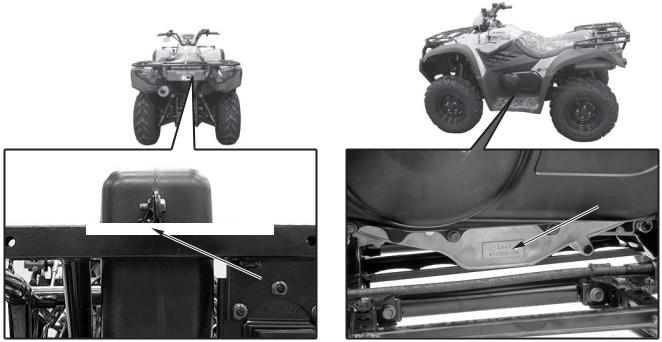
FRAME SERIAL NUMBER |
ENGINE SERIAL NUMBER |
The frame serial number is stamped on the |
The engine serial number is stamped on the left |
front and rear of the frame. |
crankcase. |
(1)
(1)
(1) Frame serial number |
(1) Engine serial number |
10
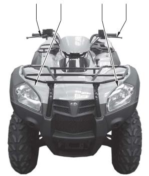
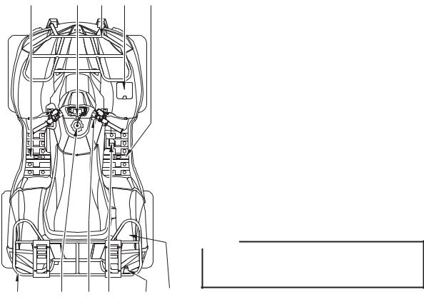
PARTS LOCATION
(03) |
(02) |
(02) |
(01) |
(01) Rear brake lever
(02) Headlights/Position lights
(03) Front brake lever
11
(04) |
(07) |
(06) |
(05) (04) |
|
|
|
|
(04) Taillights/Brake lights |
|
|
|
|
(05) |
2WD/4WD select switch and differential lock lever |
|
|
|
(06) |
Instrument and indicators |
|
|
|
(07) |
Headlight dimmer switch |
|
|
|
|
Starter button |
|
|
|
|
Engine Stop Switch |
|
|
|
|
Passing signal switch |
|
|
|
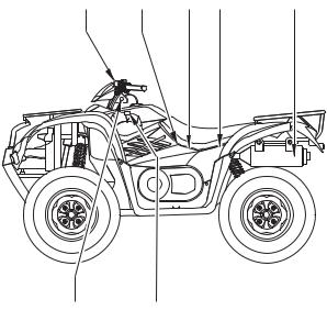
(08) |
Spark arrester |
(09)Trailer hitch (MXU 500 version only)
(10)Throttle lever
|
(10) |
(09) |
|
|
|
(08) |
|
|
|
MXU 500 IRS selectivity appurtenances |
|
|
(09) |
|
12
(23) |
(22) |
(21) (20) |
(19) |
(19) Exhaust system
(20) Battery/Fuse
(21) Tool kit
(22) Accelerating pump lever
(23) Rear brake fluid reservoir
(24) Accessory socket seat
(25) Drive select lever
(24)(25)
14

(15) |
(14)(13) |
(12) (11) |
(11) Reservoir water tank
(12) Front brake fluid reservoir
(13) Fuel valve
(14) Recoil starter
(15) Seat
(16) Brake pedal fluid reservoir
(17) Seat lock lever
(18) Oil level inspection window
(16) |
(17) |
(18) |
13
(30) |
(29) |
(28) |
(27) |
(26) |
(26) Right footpeg
(27) Owner’s manual storage
(28) Front cargo rack
(29)Ignition switch
(30)Left footpeg
(31) Rear cargo rack
(32)Fuel fill cap
(33)Choke knob
(34)Rear brake pedal
(35)Flag pole bracket
(36)Tool storage(MXU 500 IRS version only)
NOTE:
The machine you have purchased may differ slightly from those shown in the figures of this manual.
(31) |
(32) |
(33) (34) |
(35) |
(36) |
15
CONTROL FUNCTIONS
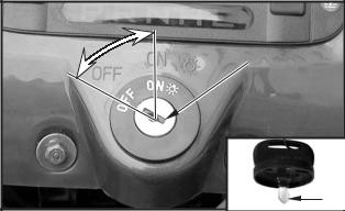
IGNITION SWITCH
Functions of the respective switch positions are as follows:
OFF:
All electrical circuits are switched off . The key can be removed in this position.
ON :
All electrical circuits are switched on. The engine can be started.
The key can not be removed.
"  “:
“:
The ignition switch is ON while the position light and taillight will light.
All electrical circuits are switched on. The engine can be started.
The key can not be removed.
|
ON |
OFF |
(1) |
|
|
|
(2) |
(1) Ignition switch |
(2) Key |
16
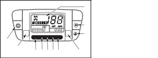
INSTRUMENTS AND INDICATOR |
|
|
|
|
|
|
|
|
|
|
(1) |
(1) Multi-function display |
|
|
|
|
|
The display includes the following functions: |
||
|
|
|
|
|
||
|
|
|
|
|
Speedometer |
|
|
2WD |
|
|
|
Odometer/Tripmeter |
|
|
4WD |
|
|
|
Digital clock |
|
|
|
|
|
(2) |
|
|
ODO |
TRIP A B |
|
|
2WD/4WD indicator |
|
|
|
|
|
|
|||
|
mile |
|
|
|
|
|
|
km PM |
|
|
|
Fuel gauge |
|
MODE |
|
SET |
|
(3) |
|
|
|
|
|
|
|||
P RN HL |
|
|
|
(2) High beam indicator |
|
|
(11) |
|
|
|
|
|
|
(10) |
|
|
|
|
The ignition switch is at the " |
" position, the |
|
|
(4) |
|
high beam indicator will light when the headlight |
||
(9) |
(8) (7) (6) (5) |
|
|
|||
|
|
switch to select High beam ( |
). |
|||
|
|
|
|
|
||
(1)Multi-function display
(2)High beam indicator
(3)Coolant temperature warning indicator
(4)Set button
(5)Low-range indicator light “L”
(6)High-range indicator light “H”
(7)Neutral indicator light “N”
(8)Reverse indicator light “R”
(9)Park indicator light “P”
(10)Mode button
(11)Differential lock indicator(MXU 500 IRS version only)
17
(3)Coolant temperature warning indicator When the coolant temperature reaches a specified level, this indicator comes on to warn that the coolant temperature is too hot. If the indicator comes on during operation, stop the engine as soon as it is safe to do so and allow the engine to cool down for about 10 minutes.
(4)Set button
This button is used to select ODO, TRIP A and TRIP B.
This button is also used to adjust the time and reset the trip meter.
(5)Low-range indicator light “L”
This indicator light comes on when the drive select lever is in the “L” position.
(6) High-range indicator light “H”
This indicator light comes on when the drive select lever is in the “H” position.
(7) Neutral indicator light “N”
This indicator light comes on when the drive select lever is in the “N” position.
(8) Reverse indicator light “R”
This indicator light comes on when the drive select lever is in the “R” position.
(9)Park indicator light “P”
This indicator light comes on when the drive select lever is in the “P” (park) position.
(10)Mode button
This button is used to select km/h, mph, km and mile.
This button is also used to adjust the time and reset the trip meter.
(11)Differential lock indicator(MXU 500 IRS only)
The front axle is equipped with a lockable differential that allows the operator to choose between an open differential or a closed differential in low traction situations.
Pulling the lock lever to the left.
To lock the differential on the 4WD, move the 4WD differential Button.
18
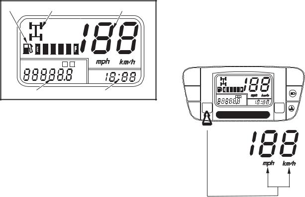
Multi-function display
(3) |
(2) |
(1) |
|
2WD |
|
|
4WD |
|
ODO |
TRIP A B |
|
|
mile |
PM |
|
km |
|
(4) |
|
(5) |
(1)Speedometer
(2)2WD/4WD indicator
(3)Fuel gauge
(4)Odometer/Tripmeter
(5)Digital clock
(1)Speedometer
Shows riding speed in km/h or mph.
Press and hold MODE button for more than 2 seconds to select mph or km/h.
|
2WD |
|
|
4WD |
|
ODO |
TRIP A B |
|
|
mile |
PM |
|
km |
MODE |
SET |
P RN HL
19
(2) 2WD/4WD indicator
Shows the drive mode is in the 2WD or 4WD.
2WD
4WD
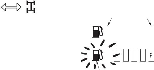
(3)Fuel gauge
The fuel gauge shows the approximate fuel supply available in a graduated display. The normal operating fuel range is with the section between the segment F and segment E. When the segment E or the fuel indicator
(3) flashes, fuel will be low and you should refill the tank as soon as possible.
(2) |
(1) |
|||||||||
|
|
|
|
|
|
|
|
|
|
|
|
|
|
|
|
|
|
|
|
|
|
|
|
|
|
|
|
|
|
|
|
|
|
|
|
|
|
|
|
|
|
|
|
(3) |
|
(1) Segment F |
(3) Fuel indicator |
(2) Segment E |
|
20
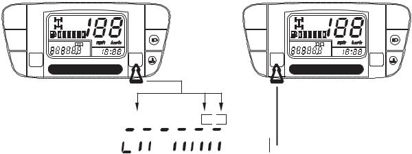
(4)Odometer/Tripmeter
The odometer shows the total mileage in Km or in miles.
The tripmeter shows the trip distance in Km or in miles.
There are two tripmeters, tripmerer A and tripmeter B
Press and hold SET button for more than 2 seconds to select ODO, TRIP A or TRIP B.
Press and hold MODE button for more than 2 seconds to select mile or km.
2WD |
|
2WD |
|
4WD |
|
4WD |
|
ODO TRIP A B |
|
ODO TRIP A B |
|
mile |
PM |
mile |
PM |
km |
km |
||
MODE |
SET |
MODE |
SET |
P RN HL |
P RN HL |
||
ODO TRIP A 
 B
B


 mile
mile


 km
km 

21
 Loading...