


 Loading...
K2500
Performance Guide
©1996All rights reserved. Kurzweil is a product line of Young Chang Co.; V.A. S. T. is a registered trademark, and Kurzweil, K2500, and K2000 are trademarks of Young Chang Co. All other products and brand names are trademarks or registered trademarks of their respective companies. Product features and specifications are subject to change without notice.
Part Number: 910251 Rev. F

RISK OF ELECTRIC SHOCK
DO NOT OPEN
CAUTION: TO REDUCE THE RISK OF ELECTRIC SHOCK, DO NOT REMOVE THE COVER
NO USER SERVICEABLE PARTS INSIDE
REFER SERVICING TO QUALIFIED SERVICE PERSONNEL
The lightning flash with the arrowhead symbol, within an equilateral triangle, is intended to alert the user to the presence of uninsulated "dangerous voltage" within the product's enclosure that may be of sufficient magnitude to constitute a risk of electric shock to persons.
The exclamation point within an equilateral triangle is intended to alert the user to the presence of important operating and maintenance (servicing) instructions in the literature accompanying the product.
IMPORTANT SAFETY & INSTALLATION INSTRUCTIONS
INSTRUCTIONS PERTAINING TO THE RISK OF FIRE, ELECTRIC SHOCK, OR INJURY TO PERSONS
WARNING - When using electric products, basic precautions should always be followed, including the following:
1.Read all of the Safety and Installation Instructions and Explanation of Graphic Symbols before using the product.
2.This product must be grounded. If it should malfunction or breakdown, grounding provides a path of least resistance for electric current to reduce the risk of electric shock. This product is equipped with a power supply cord having an equipment-grounding conductor and a grounding plug. The plug must be plugged into an appropriate outlet which is properly installed and grounded in accordance with all local codes and ordinances.
DANGER - Improper connection of the equipment-grounding conductor can result in a risk of electric shock. Do not modify the plug provided with the the product - if it will not fit the outlet, have a proper outlet installed by a qualified electrician. Do not use an adaptor which defeats the function of the equipment-grounding conductor. If you are in doubt as to whether the product is properly grounded, check with a qualified serviceman or electrician.
3.WARNING - This product is equipped with an AC input voltage selector. The voltage selector has been factory set for the mains supply voltage in the country where this unit was sold. Changing the voltage selector may require the use of a different power supply cord or attachment plug, or both. To reduce the risk of fire or electric shock, refer servicing to qualified maintenance personnel.
4.Do not use this product near water - for example, near a bathtub, washbowl, kitchen sink, in a wet basement, or near a swimming pool, or the like.
5.This product should only be used with a stand or cart that is recommended by the manufacturer.
6.This product, either alone or in combination with an amplifier and speakers or headphones, may be capable of producing sound levels that could cause permanent hearing loss. Do not operate for a long period of time at a high volume level or at a level that is uncomfortable. If you experience any hearing loss or ringing in the ears, you should consult an audiologist.
7.The product should be located so that its location or position does not interfere with its proper ventilation.
8.The product should be located away from heat sources such as radiators, heat registers, or other products that produce heat.
9.The product should be connected to a power supply only of the type described in the operating instructions or as marked on the product.
10.This product may be equipped with a polarized line plug (one blade wider than the other). This is a safety feature. If you are unable to insert the plug into the outlet, contact an electrician to replace your obsolete outlet. Do not defeat the safety purpose of the plug.
11.The power supply cord of the product should be unplugged from the outlet when left unused for a long period of time. When unplugging the power supply cord, do not pull on the cord, but grasp it by the plug.
12.Care should be taken so that objects do not fall and liquids are not spilled into the enclosure through openings.
13.The product should be serviced by qualified service personnel when:
A.The power supply cord or the plug has been damaged; or
B.Objects have fallen, or liquid has been spilled into the product; or
C.The product has been exposed to rain; or
D.The product does not appear to be operating normally or exhibits a marked change in performance; or
E.The product has been dropped, or the enclosure damaged.
14.Do not attempt to to service the product beyond that described in the user maintenance instructions. All other servicing should be referred to qualified service personnel.
15.WARNING - Do not place objects on the product's power supply cord, or place the product in a position where anyone could trip over, walk on, or roll anything over cords of any type. Do not allow the product to rest on or be installed over cords of any type. Improper installations of this type create the possibility of a fire hazard and/or personal injury.
RADIO AND TELEVISION INTERFERENCE
Warning: Changes or modifications to this instrument not expressly approved by Young Chang could void your authority to operate the instrument. Important: When connecting this product to accessories and/or other equipment use only high quality shielded cables.
Note: This instrument has been tested and found to comply with the limits for a Class B digital device, pursuant to Part 15 of the FCC Rules. These limits are designed to provide reasonable protection against harmful interference in a residential installation. This instrument generates, uses, and can radiate radio frequency energy and, if not installed and used in accordance with the instructions, may cause harmful interference to radio communications. However, there is no guarantee that interference will not occur in a particular installation. If this instrument does cause harmful interference to radio or television reception, which can be determined by turning the instrument off and on, the user is encouraged to try to correct the interference by one or more of the following measures:
•Reorient or relocate the receiving antenna.
•Increase the separation between the instrument and the receiver.
•Connect the instrument into an outlet on a circuit other than the one to which the receiver is connected.
•If necessary consult your dealer or an experienced radio/television technician for additional suggestions.
NOTICE
This apparatus does not exceed the Class B limits for radio noise emissions from digital apparatus set out in the Radio Interference Regulations of the Canadian Department of Communications.
AVIS
Le present appareil numerique n’emet pas de bruits radioelectriques depassant les limites applicables aux appareils numeriques de la class B prescrites dans le Reglement sur le brouillage radioelectrique edicte par le ministere des Communications du Canada.
SAVE THESE INSTRUCTIONS
ii

Table of Contents
Young Chang Distributors .................................................................................................. |
x |
Introduction ........................................................................................................................................... |
1-1 |
Welcome! ........................................................................................................................ |
1-1 |
For K2500R Owners ........................................................................................... |
1-1 |
Overview of the K2500 ................................................................................................... |
1-2 |
What is VAST? ............................................................................................................... |
1-3 |
How to use this manual ................................................................................................... |
1-4 |
Startup ................................................................................................................................................... |
2-1 |
Basic Startup Checklist: .................................................................................................. |
2-1 |
Startup—the Details ........................................................................................................ |
2-2 |
Before You Start... .............................................................................................. 2-2 |
|
Battery Installation .............................................................................................. |
2-2 |
Connecting the Power Cable (Line Cord) ........................................................... |
2-3 |
Connecting the Audio Cables. ............................................................................ 2-3 |
|
Connecting MIDI ................................................................................................ |
2-3 |
Connecting SCSI ................................................................................................. |
2-4 |
Switching On the Power ..................................................................................... |
2-4 |
Playing the Presets .......................................................................................................... |
2-4 |
Programs ............................................................................................................. |
2-4 |
Setups .................................................................................................................. |
2-5 |
Quick Access ...................................................................................................... |
2-6 |
Performance Controls ..................................................................................................... |
2-7 |
K2500 Boot Loader ......................................................................................................... |
2-8 |
Starting the Boot Loader ..................................................................................... |
2-8 |
Boot-loader Main Menu ...................................................................................... |
2-8 |
Install System / Install Objects ........................................................................... |
2-8 |
Run System ......................................................................................................... |
2-9 |
Hard Reset ......................................................................................................... |
2-10 |
Run Diags .......................................................................................................... |
2-10 |
Fixed Diags ....................................................................................................... |
2-10 |
Software Upgrades ........................................................................................................ |
2-10 |
User Interface Basics ............................................................................................................................ |
3-1 |
Mode Selection ............................................................................................................... |
3-1 |
Data Entry ....................................................................................................................... |
3-4 |
Intuitive Data Entry ......................................................................................................... |
3-6 |
Search Function .............................................................................................................. |
3-7 |
The Panel Play Feature (Rack Models) .......................................................................... |
3-7 |
The Mixdown and MIDI Faders Pages (Keyboard Models Only) ................................. |
3-8 |
The Operating Modes ........................................................................................................................... |
4-1 |
What the Modes Are ....................................................................................................... |
4-1 |
Selecting Modes .............................................................................................................. |
4-1 |
Using the Modes ............................................................................................................. |
4-3 |
iii

Editing Conventions .............................................................................................................................. |
5-1 |
Introduction to Editing .................................................................................................... |
5-1 |
Object Type and ID ......................................................................................................... |
5-2 |
Saving and Naming ......................................................................................................... |
5-2 |
Deleting Objects .............................................................................................................. |
5-4 |
Memory Banks ................................................................................................................ |
5-5 |
Special Button Functions ................................................................................................ |
5-6 |
Program Mode and the Program Editor ............................................................................................ |
6-1 |
K2500 Program Structure ............................................................................................... |
6-2 |
The Program Mode Page ................................................................................................. |
6-2 |
What are these programs in parentheses? ........................................................... |
6-3 |
Control Setup ...................................................................................................... |
6-3 |
The Soft Buttons in Program Mode .................................................................... |
6-4 |
Using the Program Editor ............................................................................................... |
6-4 |
Algorithm Basics ................................................................................................. |
6-5 |
Common DSP Control Parameters ................................................................................. |
6-6 |
Program Editor—Algorithm (ALG) Page ..................................................................... |
6-10 |
Program Editor—LAYER Page .................................................................................... |
6-11 |
Program Editor— KEYMAP Page ............................................................................... |
6-14 |
Program Editor— PITCH Page ..................................................................................... |
6-17 |
Program Editor—F1–F3 Pages ..................................................................................... |
6-18 |
Program Editor—F4 AMP Page ................................................................................... |
6-19 |
Program Editor—OUTPUT Page ................................................................................. |
6-21 |
Program Editor—EFFECT Page ................................................................................... |
6-24 |
Program Editor—COMMON Page ............................................................................... |
6-25 |
Program Editor—Amplitude Envelope (AMPENV) Page ........................................... |
6-28 |
Program Editor—Envelopes 2 and 3 ............................................................................ |
6-31 |
Program Editor—Envelope Control (ENVCTL) Page ................................................. |
6-32 |
Program Editor—LFO Page .......................................................................................... |
6-34 |
Program Editor—ASR Page ......................................................................................... |
6-36 |
Program Editor—FUN Page ......................................................................................... |
6-37 |
Program Editor—VTRIG Page ..................................................................................... |
6-38 |
Function Soft Buttons ................................................................................................... |
6-39 |
Setup Mode and the Setup Editor ....................................................................................................... |
7-1 |
Setup Mode ..................................................................................................................... |
7-1 |
K2500 Rack Models Only ................................................................................... |
7-2 |
The Control Setup ............................................................................................... |
7-2 |
The Setup Editor ............................................................................................................. |
7-4 |
The Channel/Program (CH/PROG) Page ....................................................................... |
7-4 |
The Key/Velocity (KEY/VEL) Page .............................................................................. |
7-9 |
The Pan/Volume (PAN/VOL) Page .............................................................................. |
7-16 |
The BEND Page ............................................................................................................ |
7-17 |
Controllers ..................................................................................................................... |
7-19 |
The MIDI Control Source List .......................................................................... |
7-21 |
Continuous Controller Parameters ................................................................................ |
7-24 |
iv

Destination (Dest) ............................................................................................. |
7-24 |
Scale .................................................................................................................. |
7-24 |
Offset (Add) ...................................................................................................... |
7-24 |
Curve (Curv) ..................................................................................................... |
7-24 |
Entry (Ent) and Exit Values .............................................................................. |
7-25 |
The SLIDER and SLID/2 Pages ................................................................................... |
7-25 |
The Continuous Control Pedal (CPEDAL) Page .......................................................... |
7-26 |
The RIBBON Page ....................................................................................................... |
7-27 |
The WHEEL Page ......................................................................................................... |
7-28 |
The Pressure (PRESS) Page .......................................................................................... |
7-29 |
Switch Controller Parameters ....................................................................................... |
7-30 |
Switch Type (SwType) ..................................................................................... |
7-30 |
Destination ........................................................................................................ |
7-30 |
On Value ........................................................................................................... |
7-30 |
Off Value .......................................................................................................... |
7-31 |
Entry (Ent) and Exit States ............................................................................... |
7-31 |
The Footswitch (FOOTSW) Page ................................................................................. |
7-31 |
The SWITCH Page ....................................................................................................... |
7-32 |
The COMMON Page .................................................................................................... |
7-32 |
The Arpeggiator (ARPEG) Page .................................................................................. |
7-33 |
The Ribbon Configuration (RIBCFG) Page ................................................................. |
7-39 |
The Utility Soft Buttons ................................................................................................ |
7-41 |
Editing Hints and Suggestions ...................................................................................... |
7-44 |
Do These Parameters Always Mean Something? ............................................. |
7-44 |
Do I Need All Those Pedals? ............................................................................ |
7-44 |
Multiple Controllers .......................................................................................... |
7-44 |
Editing Programs .............................................................................................. |
7-44 |
Quick Access Mode and the |
|
Quick Access Editor .............................................................................................................................. |
8-1 |
Effects Mode and the Effects Editor ................................................................................................... |
9-1 |
The Effects Mode Page ................................................................................................... |
9-1 |
The Soft Buttons on the Effects mode Page ....................................................... |
9-1 |
Effects Mode Parameters ................................................................................................ |
9-2 |
Understanding FX Mode and FX Channel ......................................................... |
9-2 |
Another Use for Effects Mode ............................................................................ |
9-5 |
The Effects Editor ........................................................................................................... |
9-6 |
Editing Effects .................................................................................................... |
9-6 |
Configurations and Parameters ....................................................................................... |
9-7 |
MIDI Mode .......................................................................................................................................... |
10-1 |
The Transmit (XMIT) Page .......................................................................................... |
10-1 |
The Receive (RECV) Page ........................................................................................... |
10-4 |
........................................................................................................................... |
10-6 |
The Channels Page ........................................................................................................ |
10-8 |
Parameter Locks ................................................................................................ |
10-9 |
Program Change Formats ........................................................................................... |
10-10 |
v

Extended and Kurzweil Program Change Types ............................................ |
10-11 |
The Soft Buttons in MIDI Mode ................................................................................. |
10-18 |
Master Mode ........................................................................................................................................ |
11-1 |
The Master Mode Page ................................................................................................. |
11-1 |
The Soft Buttons in Master Mode ................................................................................. |
11-4 |
Guitar/Wind Controller Mode ....................................................................................... |
11-5 |
Object Utilities .............................................................................................................. |
11-6 |
Move ................................................................................................................. |
11-7 |
Copy .................................................................................................................. |
11-8 |
Name ................................................................................................................. |
11-9 |
Delete ................................................................................................................ |
11-9 |
Dump ............................................................................................................... |
11-10 |
Accessing the Object Utilities from the Editor ............................................... |
11-10 |
Song Mode ........................................................................................................................................... |
12-1 |
Getting Started with the Sequencer ............................................................................... |
12-1 |
A Word about the Local Keyboard Channel ..................................................... |
12-1 |
Tutorial: Recording a song ................................................................................ |
12-2 |
MAIN Page ................................................................................................................. |
12-11 |
Soft Buttons on the MAIN Page ..................................................................... |
12-15 |
Save this song? Dialog .................................................................................... |
12-16 |
Save New song? Dialog .................................................................................. |
12-17 |
Erase Track Dialog .......................................................................................... |
12-17 |
MISC Page .................................................................................................................. |
12-18 |
Soft Buttons on the MISC Page ...................................................................... |
12-22 |
MIX Page .................................................................................................................... |
12-23 |
Soft Buttons on the MIX Page ........................................................................ |
12-24 |
The Edit Song Pages ................................................................................................... |
12-25 |
Edit Song: COMMON Page ....................................................................................... |
12-25 |
Parameters used with the Arrangement Feature ............................................. |
12-26 |
Soft Buttons on the Edit Song: COMMON Page ........................................... |
12-27 |
Edit Song: EVENT Page ............................................................................................. |
12-28 |
Soft Buttons on the Edit Song: EVENT Page ................................................. |
12-29 |
Edit Song: TRACK Page ............................................................................................ |
12-31 |
Common Parameters for Edit Song: Track Functions .................................... |
12-32 |
Region / Criteria Window Parameters ............................................................ |
12-32 |
Soft Buttons on the Edit Song: Track Page ..................................................... |
12-33 |
Edit Song: Track Functions – Erase ............................................................................ |
12-34 |
Edit Song: Track Functions – Copy ............................................................................ |
12-34 |
Edit Song: Track Functions – Bounce ........................................................................ |
12-35 |
Edit Song: Track Functions – Insert ........................................................................... |
12-35 |
Edit Song: Track Functions – Delete .......................................................................... |
12-36 |
Edit Song: Track Functions – Quantize ...................................................................... |
12-36 |
Edit Song: Track Functions – Reference Quantize ..................................................... |
12-37 |
Edit Song: Track Functions – Shift ............................................................................. |
12-38 |
Edit Song: Track Functions – Transpose .................................................................... |
12-39 |
vi

Edit Song: Track Functions – Change ........................................................................ |
12-39 |
Edit Song: Track Functions – Thin ............................................................................. |
12-40 |
Edit Song: Track Functions – Remap ......................................................................... |
12-41 |
Edit Song: Track Functions – Grab ............................................................................ |
12-41 |
Edit Song: STEP Page ................................................................................................ |
12-43 |
Recording with the STEP editor ..................................................................... |
12-43 |
Soft Buttons on the Edit Song: STEP Page .................................................... |
12-45 |
Edit Song: ARRANGE Page ...................................................................................... |
12-46 |
Triggering Steps from a Key ........................................................................... |
12-48 |
Soft Buttons on the Edit Song: ARRANGE Page .......................................... |
12-49 |
Selecting a Song for Playback .................................................................................... |
12-49 |
Effect Selection During Recording and Playback ...................................................... |
12-50 |
Synchronizing Songs ...................................................................................... |
12-50 |
Memory Limits ........................................................................................................... |
12-51 |
Loading Songs From Disk .......................................................................................... |
12-51 |
Recording Multi-timbral Sequences via MIDI ........................................................... |
12-52 |
Disk Mode ............................................................................................................................................ |
13-1 |
Disk Mode Page ............................................................................................................ |
13-1 |
File List Dialog ............................................................................................................. |
13-6 |
Creating Directories .................................................................................................... |
13-11 |
Creating a Directory with NewDir .................................................................. |
13-11 |
Creating a Directory with the Save and NewDir Soft Buttons ....................... |
13-12 |
The Directory Selection Dialog .................................................................................. |
13-12 |
Disk Mode Functions .................................................................................................. |
13-13 |
Loading Files .................................................................................................. |
13-13 |
Loading Individual Objects ............................................................................. |
13-13 |
Shortcuts when Loading Objects .................................................................... |
13-16 |
Loading Dependents of Selected Objects ....................................................... |
13-17 |
Auditioning Samples from a Disk File ........................................................... |
13-17 |
Loading Objects from Floppy Disk Files ........................................................ |
13-18 |
Load Function Dialog ................................................................................................. |
13-18 |
Bank Status Indicator ...................................................................................... |
13-18 |
Loading Methods ............................................................................................ |
13-18 |
Multiple Selection of Files to Load ................................................................ |
13-21 |
Aborting a Multiple File Load ........................................................................ |
13-21 |
More Load Function Enhancements ............................................................... |
13-22 |
Saving Files ................................................................................................................. |
13-22 |
Saving Individual Objects ............................................................................... |
13-24 |
Shortcuts when Saving Objects ...................................................................... |
13-24 |
Auditioning Objects in RAM .......................................................................... |
13-25 |
Saving Dependent Objects .............................................................................. |
13-26 |
The Name Table .............................................................................................. |
13-27 |
Working with Relink-by-Name ...................................................................... |
13-28 |
Not Loading the Name Table .......................................................................... |
13-31 |
Relink-by-Name Processing Time .................................................................. |
13-31 |
vii

The Multiple Object Selector Page ............................................................................. |
13-32 |
Macros ......................................................................................................................... |
13-38 |
The Macro Page .............................................................................................. |
13-38 |
Macro Modes .................................................................................................. |
13-39 |
The Macro Table ............................................................................................. |
13-40 |
How to Make a Macro File ............................................................................. |
13-41 |
Macro Entries .................................................................................................. |
13-45 |
Using the Bank and Mode Fields .................................................................... |
13-46 |
Viewing the Object List for a Macro Entry .................................................... |
13-46 |
Unspecified Disk Drive ID ............................................................................. |
13-47 |
The Library Disk ............................................................................................. |
13-47 |
Loading Selected Entries from a Macro File .................................................. |
13-49 |
Editing Macros ................................................................................................ |
13-50 |
Macro Insert .................................................................................................... |
13-53 |
Saving and Loading a Macro Table in a .KRZ file ......................................... |
13-54 |
Aborting a Macro Load ................................................................................... |
13-54 |
Remote Macro Load ........................................................................................ |
13-55 |
Disk Utilities ............................................................................................................... |
13-56 |
Find Files ......................................................................................................... |
13-56 |
List .................................................................................................................. |
13-58 |
Free .................................................................................................................. |
13-58 |
Moving Files Between Directories ................................................................. |
13-59 |
Renaming Files ............................................................................................... |
13-61 |
Deleting Files and Directories ......................................................................... |
13-61 |
Backup and Copy Functions ....................................................................................... |
13-62 |
File Copy ......................................................................................................... |
13-64 |
Creating a Startup File ................................................................................................ |
13-65 |
Deleting Banks in a Startup File ..................................................................... |
13-65 |
MS-DOS File System Compatibility .......................................................................... |
13-66 |
File Name Compatibility ................................................................................. |
13-66 |
Importing and Exporting Data using Standard File Formats ...................................... |
13-67 |
AIFF and AIFF-C Files ................................................................................... |
13-67 |
WAVE Files .................................................................................................... |
13-68 |
Standard MIDI Files (MIDI Type 0 and Type 1 Files) ................................... |
13-68 |
DSP Functions ..................................................................................................................................... |
14-1 |
Introduction to Algorithm Programming ...................................................................... |
14-1 |
Additional Parameters ....................................................................................... |
14-3 |
Filters ............................................................................................................................ |
14-5 |
How to read the graphs ..................................................................................... |
14-6 |
Equalization (EQ) ....................................................................................................... |
14-22 |
Pitch / Amplitude / Panner .......................................................................................... |
14-31 |
Mixers ......................................................................................................................... |
14-34 |
Waveforms .................................................................................................................. |
14-35 |
Added Waveforms ...................................................................................................... |
14-38 |
Non-linear Functions ................................................................................................... |
14-38 |
viii

Waveforms Combined with Non-linear Functions ..................................................... |
14-48 |
Mixers with Non-linear Inputs .................................................................................... |
14-50 |
Hard Sync Functions ................................................................................................... |
14-51 |
Sampling and Sample Editing ........................................................................................................... |
15-1 |
Setting Up For Sampling .............................................................................................. |
15-1 |
Cables and Input Jacks ...................................................................................... |
15-1 |
Entering The Sampler - Two Different Ways ............................................................... |
15-2 |
Sampling Analog Signals .............................................................................................. |
15-2 |
Recording Samples ........................................................................................... |
15-6 |
Sampling the K2500’s Output ...................................................................................... |
15-8 |
Using the Sampler to Create Overdubs ......................................................................... |
15-8 |
Sampling Digital Signals ............................................................................................ |
15-10 |
Using the Digital Outputs ........................................................................................... |
15-11 |
Editing Samples .......................................................................................................... |
15-12 |
Crossfade and Volume Adjust Curves ............................................................ |
15-33 |
Reading Samples ......................................................................................................... |
15-34 |
The Keymap Editor ..................................................................................................... |
15-36 |
Building a Keymap ..................................................................................................... |
15-41 |
Using the Analog Inputs to Trigger Samples .............................................................. |
15-42 |
FUNS .................................................................................................................................................... |
16-1 |
The Mechanics of Control Sources ............................................................................... |
16-1 |
Programming the FUNs ................................................................................................ |
16-2 |
The FUN Equations ...................................................................................................... |
16-3 |
The List of Equations ........................................................................................ |
16-4 |
Warp Equations ............................................................................................... |
16-10 |
Sawtooth LFOs ............................................................................................... |
16-13 |
Chaotic LFOs .................................................................................................. |
16-13 |
Diode Equations .............................................................................................. |
16-14 |
The Order of Evaluation for FUNs ............................................................................. |
16-16 |
Other Editors ....................................................................................................................................... |
17-1 |
The Intonation Table Editor .......................................................................................... |
17-1 |
The Velocity Map Editor .............................................................................................. |
17-3 |
Using the Velocity Map Editor ..................................................................................... |
17-3 |
The Pressure Map Editor .............................................................................................. |
17-6 |
Audio Outputs ..................................................................................................................................... |
18-1 |
Audio Configurations .................................................................................................... |
18-1 |
Using the MIX Outputs ................................................................................................. |
18-1 |
Using the Separate Outputs ........................................................................................... |
18-2 |
Output Groups and MIDI Channels .............................................................................. |
18-4 |
Programming Examples ..................................................................................................................... |
19-1 |
Example 1 - Trumpet with Delayed Vibrato and Velocity-triggered Fall-offs ............ |
19-1 |
Example 2 - Lowpass Filter, Envelopes ....................................................................... |
19-4 |
Example 3 - Sample and Hold; Using a FUN ............................................................... |
19-6 |
Example 4 - SHAPER and PANNER ........................................................................... |
19-7 |
Example 5 - Building a Drum Program; Using the Keymap Editor ............................. |
19-9 |
ix

Young Chang Distributors
Contact the nearest Young Chang office listed below to locate your local Young Chang/ Kurzweil representative.
Young Chang America, Inc.
13336 Alondra Blvd.
Cerritos, CA 90703-2245
Tel: (310) 926-3200
Fax: (310) 404-0748
Young Chang Co.
Kang Nam P.O.Box 998
Seoul, Korea
Tel: 011-82-2-3451-3500
Fax: 011-82-2-3451-3599
Young Chang Akki Europe GmbH
Industriering 45
D-41751 Viersen
Germany
Tel: 011-49-2162-4491
Fax: 011-49-2162-41744
Young Chang Canada Corp.
395 Cochrane Drive
Markham, Ontario L3R 9R5
Tel: (905) 513-6240
Fax: (905) 513-9445
x

Introduction
Welcome!
Chapter 1
Introduction
Welcome!
Congratulations, and thanks for purchasing a Kurzweil/Young Chang K2500 Series instrument. Whether you’ve just gotten a K2500 (illustrated below), the 88-note K2500X, or the rack-mountable K2500R, you’ve got your hands on an extremely capable musical instrument. The K2500 Series instruments are packed with great acoustic, electric, and synth sounds— combined with some of the most advanced synthesis features available, which you can use to create almost any sound imaginable. If you liked the award-winning K2000, you’ll love the K2500!
This manual and the accompanying Reference Guide, as well as the video tutorial, will get you started with your new instrument. You’ll definitely want to keep the manuals handy as you become an advanced user, too.
Headphones |
|
Mix |
|
|
D |
|
Audio Outs |
C |
|
|
B |
|
|
A |
|
|
|
|
|
|
|
|
|
|
MIDI Select |
|
MIDI |
SCSI |
|
Switch Pedals |
|
CC Pedals / Breath |
KDS Output |
Power |
|||
R |
L |
R |
L |
R |
L |
R |
L |
R |
L |
Optical Out |
|
Digital Out |
Digital In |
Optical In |
LoZ Left In |
LoZ Right In |
HiZ In |
Out |
Thru |
Out |
Out/Thru |
In |
4 |
3 |
2 |
1 |
Breath |
2 |
1 |
|
|||||||
|
|
|
|
|
|
|
|
|
|
|
|
|
|
|
|
|
|
|
|
|
|
|
|
|
|
|
|
|
SCSI Thru |
|
|
|
|
or |
|
|
|
|
|
|
|
|
|
|
|
|
Assignable Controllers |
|
|
|
|
|
|
|
|
|
|
|
|
|
|
|
|
|
Data Entry |
|
|
|
|
|
|
|
|
||
|
|
|
|
|
|
|
|
|
1 |
|
2 |
|
3 |
|
4 |
5 |
6 |
7 |
8 |
|
|
|
|
|
|
|
|
|
|
|
|
|
|
|
|
|
|
|
|
|
|
|
|
|
Master Volume |
|
A |
|
B |
|
C |
|
D |
E |
F |
G |
H |
|
|
Program |
MIDI |
|
|
|
|
|
|
|
|
|
|
|
|
|
K2500 |
|
|
|
|
|
|
|
|
|
|
|
|
|
|
|
|
|
|
|
|
|
Mute 1 |
|
|
Previous Pg |
|
|
|
|
|
|
|
|
|
1 |
2 |
3 |
|
|
|
|
|
|
|
|
|
|
|
|
|
|
|
|
|
|
|
|
|
|
Zoom - |
|
|
Gain - |
|
|
|
|
|
|
|
|
|
ABC |
DEF |
GHI |
|
|
|
|
|
|
|
|
|
|
|
|
|
|
|
|
|
|
|
|
|
|
|
Setup |
Master |
|
|
|
|
|
|
|
|
|
|
|
|
|
Forty-Eight Voices |
|
|
|
|
|
|
|
|
|
|
|
|
|
|
|
|
|
|
|
|
|
Mute 2 |
|
|
Mark |
|
|
|
|
|
|
|
|
|
4 |
5 |
6 |
Digital Multi Effects |
|
|
|
|
|
|
|
|
|
|
|
|
|
|
|
|
|
|
|
|
|
Zoom + |
|
|
Gain + |
|
|
|
|
|
|
|
|
|
JKL |
MNO |
PQR |
|
|
|
|
|
|
|
|
|
|
Solo |
|
|
|
|
|
|
|
|
|
|
|
|
Q Access |
Song |
|
Chan/Bank |
|
|
|
|
|
|
|
|
Multi-Track Sequencer |
|||
|
|
|
|
|
|
|
|
|
|
|
|
|
|
|
|
|
|
|
|
Mute 3 |
Jump |
|
|
|
|
|
|
|
|
|
7 |
8 |
9 |
||||
|
|
|
|
|
|
|
|
|
|
|
|
|
|
|
|
|
|
|
|
|
|
|
|
|
|
|
|
|
|
|
|
Expandable to 28MB of Sound ROM |
|||||
|
|
|
|
|
|
|
|
|
|
|
|
|
|
|
|
|
|
|
|
|
Samp/Sec |
|
|
Link |
|
|
|
|
|
|
|
|
|
STU |
VWX |
YZ |
|
|
|
|
|
|
|
|
|
|
Mixdown |
|
|
|
|
|
|
|
|
|
|
|
|
Effects |
Disk |
|
Layer/Zone |
|
|
|
|
|
|
|
|
Expandable to 128MB of Sample RAM |
|||
|
|
|
|
|
|
|
|
|
|
|
|
|
|
|
|
|
|
|
|
|
|
|
|
|
|
|
|
|
|
|
+/- |
0 |
|
||||
|
|
|
|
|
|
|
|
|
|
|
|
|
|
|
|
|
|
|
|
|
FX Bypass |
|
|
Compare |
|
|
|
|
|
|
|
|
|
Clear |
|
||
|
|
|
|
|
|
|
|
MIDI Faders |
|
|
|
|
|
|
|
|
|
|
|
Record |
Play/Pause |
Stop |
|
Edit |
|
|
|
Exit |
|
|
|
|
UPPER/lower |
0 - 9 |
Space |
|
|
|
|
|
|
|
|
|
|
|
|
|
|
|
|
|
|
|
|
|
|
|
|
|
|
|
|
|
|
|
|
|
|
|
|
Cancel |
|
Enter |
Variable Architecture Synthesis Technology |
|
|
|
|
|
|
|
|
|
|
|
|
|
|
|
|
|
|
|
|
|
|
|
|
|
|
|
|
|
|
|
|
|
|
|
|
|
|
|
|
|
|
|
|
|
|
|
|
|
|
|
|
|
|
|
|
|
|
|
|
|
|
|
C4 |
|
|
|
|
|
|
|
|
|
|
|
|
SW1 |
SW2 |
|
|
|
|
|
|
|
|
|
|
|
|
|
|
|
|
|
|
|
|
|
|
|
|
|
|
|
|
|
|
|
|
|
|
|
|
For K2500R Owners
Sampler |
Variable Architecture Synthesis Technology |
Throughout the Performance Guide and Reference Guide we’ve simplified things by saying just "K2500" any time we’re referring to features that are common to all instruments in the K2500 Series. Obviously, though, there are some differences between the rack and keyboard models; we’ll point them out where they occur and mark them with a handy K2500R margin symbol such as the one to the left of this paragraph.
1-1

Introduction
Overview of the K2500
Overview of the K2500
The K2500 has been designed to be a versatile instrument both for performance, and for multitimbral sequencing and recording. Its Variable Architecture Synthesis Technology lets you build sounds from realistic instrumental samples and sampled synth waveforms—then modify the nature of those sounds through a dazzling array of digital signal processing (DSP) functions. The K2500 also generates its own synth waveforms, which can be combined with the samples or used on their own. The K2500 packs 8 Megabytes of on-board sound ROM, and you can load samples from disk into optional sample RAM.
Before we get into explaining Variable Architecture Synthesis, here are a few of the features that by themselves make the K2500 an impressive stage and studio machine. It’s fully multi- timbral—different programs can be played on each MIDI channel. It’s 48-note polyphonic, for a full sound no matter how many chords you play. There’s an on-board digital effects processor, providing up to four simultaneous effects, including realtime effects control, internally or via MIDI.
In addition to the standard stereo audio output pair, there are eight separate outputs that can be configured as stereo pairs, or as individual mono outputs. You can also use the separate outputs as insert points for outboard gear.
The K2500 offers eight SIMM sockets (single, in-line memory modules) so you can add optional sample RAM, where you can store samples that you’ve loaded from disk. You can add up to 128 megabytes of sample RAM! (Sample RAM is not battery-backed, so RAM samples are erased from memory when you power down.)
For offline storage, there’s also a floppy drive and two SCSI ports, so you can store files on floppies or on an external hard disk or load them from a CD-ROM drive. The two SCSI ports make it easy to chain multiple SCSI devices together. There’s also provision for an internal SCSI hard disk. You’ll find all this storage potential extremely useful for saving and loading samples, which can be transferred to and from the K2500 using the standard MIDI sample transfer format, or the new, faster, parallel SMDI sample transfer format (SCSI Musical Data Interchange). See the Reference Guide for information about MIDI and SMDI sample transfers.
The K2500’s battery-backed RAM will store about 400 of your own programs, or 30,000 notes recorded in the sequencer. This sequencer (Song mode) lets you play back MIDI type 0 sequences, record and play back your own songs, and record multi-timbral sequences received via MIDI. For more onboard storage you can add the P/RAM option, which will increase your battery-backed RAM to about 1250K, enough to store hundreds of additional programs, setups, songs, and other objects.
The Local Keyboard Channel feature enables you to use the K2500’s tri-zone setups even if your MIDI controller can transmit on only one channel. The K2500 will also rechannelize incoming MIDI information and send it to its MIDI Out port, enabling you to control additional synths on three different channels.
An optional sampling feature is available, allowing you to make your own mono or stereo samples using analog or digital inputs.
And, of course, there’s the incomparable Kurzweil sound. The K2500 comes to you with 200 preset factory programs (called patches, presets, voices, etc. on other synths), as well as 100 multi-zone performance setups. Play them straight from the box, tweak them in any number of ways, or develop your own programs from scratch—which brings us back to the powerful programming capabilities of the K2500.
1-2

Introduction
What is VAST?
What is VAST?
Variable Architecture Synthesis gives the K2500 its unprecedented flexibility. While many other synthesizers offer a fixed set of DSP tools (typically filtering, pitch, and amplitude modulation) the K2500’s Variable Architecture lets you arrange a combination of any five DSP functions from a long list of choices. The functions you choose define the type of synthesis you use.
Each layer of every program has its own DSP architecture, what we call an algorithm. Within each algorithm, you can select from a variety of DSP functions. Each function can be independently controlled by a variety of sources including LFOs, ASRs, envelopes, a set of unique programmable functions (FUNs), as well as any MIDI control message. The many different DSP functions and the wealth of independent control sources give you an extremely flexible, truly vast collection of tools for sound creation and modification.
Variable Architecture Synthesis Technology
How the K2500 Works
The K2500 integrates two MIDI-driven components: a sound engine, and a global effects processor. The sound engine responds to the MIDI events generated by your MIDI controller and turns them into sounds that are processed within the variable architecture of the algorithms. The resulting sound can then be routed through the effects processor and to the MIX or separate audio outputs.
1-3

Introduction
How to use this manual
How to use this manual
This manual includes the following:
•how to connect and power up your K2500, getting around the front panel, and a brief description of the operating modes.
•basic editing, including the normal operations of each operating mode.
•the advanced programming features that make the K2500 so powerful—a number of familiar synthesis tools and quite a few new ones.
Even if you’re a complete techie, you should read Chapter 3, User Interface Basics. Here you’ll get a tour of the K2500’s front panel and learn how to navigate through the major functions.
Chapter 4 describes the concept and operation of the K2500’s eight operating modes, with a brief description of each. Chapters 6 through 13 describe each mode in detail, including the editors contained within them. Chapters 14 through 17 discuss the advanced editing features. Chapter 18 shows you how to use the multiple audio outputs to suit your needs. Chapter 19 is a programming tutorial, giving you specific examples of many of the K2500’s programming functions. Some are basic, some are advanced. By working through the tutorials, you’ll become familiar with many synthesis techniques, and you’ll get a first-hand look at how to unleash the power of the K2500.
When manual text appears in boldface italic (like this), you’ll find it described in the Glossary in the Reference Guide. Only the first one or two occurrences of these words are highlighted.
The best way to read this manual is with your K2500 in front of you. By trying the examples we give to illustrate various functions, you can get a quick understanding of the basics, then move on to the more advanced features.
If you like to figure out your equipment for yourself, and normally use manuals only as reference sources, you’ll probably get the most use out of the Reference Guide that accompanies this manual, which contains brief descriptions of the K2500’s major operating features, and all sorts of useful lists—programs, keymaps, algorithms, effects, control sources, and more. A glossary and complete specifications for the K2500 are also included in the Reference Guide.
1-4

Startup
Basic Startup Checklist:
Chapter 2
Startup
If hooking up new gear is familiar to you, and you just want to get going, here’s a quick description of all the basic things you need to cover to get started with your K2500. The procedure is pretty much the same whether you have a rack or a keyboard model. If you need more information, thorough descriptions of each step follow. In either case, check out “Playing the Presets,” later in this chapter.
Basic Startup Checklist:
•Install the supplied batteries (if they are packaged separately). See "Battery Installation" on page 2-2.
•Mount your K2500R securely in a standard 19-inch MIDI rack, or set it on a hard flat surface. Keyboard models should either be placed on a sturdy keyboard stand or table. In either case, make sure to leave plenty of room for ventilation.
•Connect the power cable.
•Make sure your sound system is at a safe volume level.
•Plug in a pair of stereo headphones or run standard (1/4-inch) audio cables from your amplifier or mixer to the MIX audio outputs on the K2500 (Use the MIX L out for mono). It’s good practice to make the cable connection to the K2500 (or any instrument) last, since this will reduce the chance of creating static electricity that can cause an audible "pop" (and, in extreme cases, cause equipment damage).
Sampler |
Variable Architecture Synthesis Technology |
K2500R Only
•IMPORTANT: If you will be transporting the rack containing the K2500R, you must support the back of the unit. It’s fairly heavy, and you don’t want your K2500R to get damaged when you move the rack around.
•Most likely, you will connect a MIDI controller to your K2500R. Connect a MIDI cable from the MIDI Out port of your MIDI controller to the MIDI In port of the K2500R.
•If your MIDI controller can transmit on more than one MIDI channel, check out Setup mode by pressing the Setup mode button. Then use the Alpha Wheel to select tri-zone setups with independent programs, MIDI channels and controller assignments in each zone.
Start Jamming!
•Power up your K2500 and begin making some music.
•If you hear distortion, reduce the gain on your mixing board, or use the pad if it has one.
•Scroll through the Program list with the Alpha Wheel (the large knob to the right of the display).
•Press the Quick Access mode button and use the numeric keys to select from programmable banks of ten programs or setups.
•If you don’t hear anything, review these steps, or check the Troubleshooting section in the
Reference Guide.
2-1

Startup
Startup—the Details
Startup—the Details
This section will walk you through the hookup of your K2500. We’ll take a look at the rear panel, then describe the power, audio, and other cable connections.
Before You Start...
Don’t connect anything until you make sure your K2500 is properly and safely situated. Also, if your K2500 has been out in the cold, give the unit a little time to warm up to room temperature before starting it, since condensation may have formed inside the K2500.
Sampler |
Variable Architecture Synthesis Technology |
You’ll probably be mounting a K2500R in a standard 19-inch MIDI rack (it takes up three rack |
|
|
spaces). If you will be transporting the rack containing the K2500R, be sure to support the back |
|
|
of the K2500R within the rack. If you’re not installing the K2500R in a rack, it should rest on a |
|
|
hard flat surface. In this case, it must rest on its rubber feet (supplied in the packing carton), and |
|
|
NOT on the bottom panel. |
NEVER block the ventilation openings on the bottom or rear panels; doing so can cause overheating and serious damage. To provide adequate ventilation, the rear panel should be at least four inches from any vertical surface. There are no user-serviceable parts in the K2500. Under no circumstances should you attempt to remove any panels (except for battery installation or replacement). If you attempt to open your K2500, you’ll risk electric shock, and you’ll void your product warranty.
Battery Installation
We’ve included three AA batteries for your K2500’s battery-backed RAM. Depending on when your K2500 was shipped, we may not have installed the batteries at the factory because they would drain during shipping. If you’ve found three batteries shipped in the box with your unit, you should install the batteries before you start up your K2500. Otherwise, continue on to the next section.
Locate the battery compartment in the lower right-hand corner of the rear panel of the K2500R (refer the illustration on the following page) or the small door on the bottom of the K2500 keyboard models, as shown below.
Battery Compartment
Sampler |
Variable Architecture Synthesis Technology |
Remove the battery compartment cover by inserting a flat-head screwdriver or coin into its slot, |
|
then turning it counterclockwise until it pops out. Slide the three batteries, all positive side out, |
|
into the compartment. Install the battery compartment cover by lining up the tabs, pushing the |
|
cap inward, then turning it 90°. |
When you start up your unit for the first time after installing the batteries, it will take a few minutes to initialize all of its memory. This will not happen on every power up.
2-2
Startup
Startup—the Details
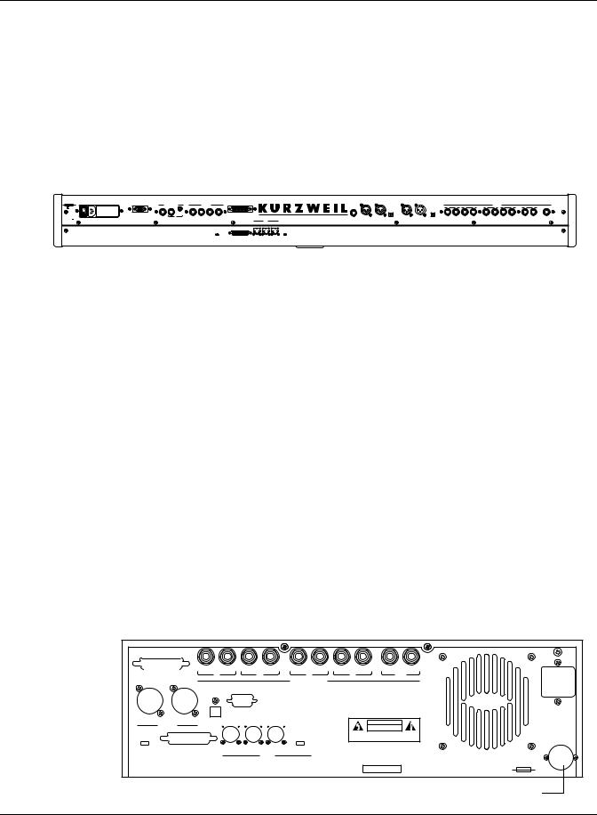
Connecting the Power Cable (Line Cord)
The K2500 runs on 100-, 120-, 220-, or 240-Volt AC power at 50—60 Hz. Your dealer will set the voltage switch to match the voltage in your area. The voltage level is set with a selector on the rear panel of the keyboard models of the K2500. On the K2500R, however, the voltage setting can only be changed by an authorized Kurzweil service center.
When you’ve connected the cable at the K2500 end, plug it into a grounded outlet. If your power source does not have the standard three-hole outlet, you should take the time to install a proper grounding system. This will assure you of avoiding problems with audio hum, and will reduce the risk of a shock hazard.
|
|
KDS Output |
|
CC Pedals / Breath |
|
Switch Pedals |
|
SCSI Thru |
|
|
|
|
100/120V F 2.0A 250V slow-blow |
|
1 |
2 |
1 |
2 |
3 |
4 |
|
|
|
|
|
230/240V F 1.0A 250V slow-blow |
|
|
|
|
|
|||||||
|
|
|
|
|
Breath |
|
|
|
|
|
|
|
|
|
|
|
or |
|
|
|
|
|
|
|
|
100/120/230/240V |
AC |
WARNING REPLACE ONLY WITH THE SAME TYPE AND RATING OF FUSE. |
|
|
|
|
SCSI Termination |
SCSI |
MIDI |
|
MIDI Select |
|
50-60 Hz |
|
|
|
|
|
|
||||||
1.5/.75 A |
|
FOR CONTINUED PROTECTION AGAINST THE RISK OF FIRE, |
|
|
|
|
|
|
|
|
|
|
|
|
ATTENTION UTILISER UN FUSIBLE DE RECHANGE DE MEME TYPE. |
|
|
|
|
Disable |
Enable |
In |
Thru/Out |
Out |
Thru Out |
 K2500
K2500
|
|
|
|
|
|
|
|
Audio Outs |
|
|
|
|
|
L |
A |
R |
L |
B |
R |
L |
C |
R |
L |
D |
R |
L Mix R |
Headphones |
|
|
|
|
|
|
|
|
|
|
|
|
(mono) |
|
HiZ In |
LoZ Right In |
LoZ Left In |
Optical In |
Digital In |
Digital Out |
Optical Out |
Ring=Right |
|
|
|
|
|
|
Tip=Left |
|
|
|
|
|
|
Connecting the Audio Cables
Did you turn down the level on your PA yet?!
After you’ve turned down the level on your sound system, you can rig the K2500’s audio connections using a pair of mono audio cables. You’ll find ten 1/4-inch jacks near the top of the rear panel. For now, connect one end of each audio cable to your mixing board or PA system inputs, and connect the other end to the jacks marked MIX L and R on the rear panel of the K2500. If you have only one input available, use the K2500’s MIX L output to get the full signal in mono.
It’s always a good idea to make the cable connection to the K2500 (or any instrument) after you’ve made your other audio connections, since this will reduce the chance of creating static electricity that can cause an audible "pop" (and, in extreme cases, cause equipment damage). Turn to Chapter 18 for more detailed information about the K2500’s audio configuration.
Connecting MIDI
The simplest MIDI configuration uses a single MIDI cable, from the MIDI Out port of your MIDI controller to the MIDI In port of the K2500. There are all sorts of possible configurations, including additional synths, personal computers, MIDI effects processors, and MIDI patch bays. Depending on your system, you may want to use the K2500’s MIDI Thru port to pass MIDI information from your MIDI controller to the K2500 and on to the next device in your system. You can also connect MIDI devices to the K2500’s MIDI Out port, which can send channelized MIDI information from your MIDI controller. See the discussion of the Local Keyboard Channel parameter in Chapter 10.
NOTE: You can perform a quick check of the K2500R and your audio system without a MIDI controller connected to the K2500R. Hold down the CANCEL button on the alphanumeric pad and press any other alphanumeric button, and you should hear notes. See "The Panel Play Feature" in Chapter 3 for more information about this feature.
|
L |
R |
L |
R |
L |
R |
L |
R |
L |
R |
SCSI Thru |
A |
|
B |
|
C |
|
D |
|
Mix |
|
Audio Outs
|
|
KDS Output |
|
|
|
|
|
In |
Out |
Optical Out |
|
|
|
|
CAUTION |
Digital |
|
|
|
|
|
|
|
|
|
|
|
|
|
RISK OF ELECTRIC SHOCK |
|
|
|
|
|
|
|
|
DO NOT OPEN |
SCSI Term. |
|
|
|
|
MIDI Select |
ATTENTION: RISQUE DE CHOC ELECTRIQUE |
|
|
|
|
|
|
NE PAS OUVRIR |
||
|
|
|
|
|
|
|
|
Disable / Enable |
SCSI |
In |
Thru / Out |
Out |
Thru / Out |
WARNING: TO REDUCE RISK OF FIRE OF ELECTRIC |
|
SHOCK, DO NOT EXPOSE THIS PRODUCT TO RAIN OR |
|||||||
|
|
|
MIDI |
|
MOISTURE. |
|
|
|
|
|
|
|
|
||
THIS DEVICE COMPLIES WITH PART 15 OF THE FCC RULES. OPERATION IS SUBJECT TO THE FOLLOWING |
|
|
|
|
|||
TWO CONDITIONS: (1) THIS DEVICE MAY NOT CAUSE HARMFUL INTERFERENCE, AND (2) THIS DEVICE MUST |
|
Mfr: Young Chang Akki, Co., LTD |
Serial No. |
Made in Korea |
|||
ACCEPT ANY INTERFERENCE RECEIVED, INCLUDING INTERFERENCE THAT MAY CAUSE UNDESIRED OPERATION. |
|
||||||
WARNING: FOR CONTINUED PROTECTION AGAINST THE RISK OF FIRE, REPLACE ONLY WITH SAME TYPE AND RATING OF FUSE.
ATTENTION: UTILISER UN FUSIBLE DE RECHANGE DE MEME TYPE.
100/120V ~ T 2.00A 250V SLOW-BLOW 220/240V ~ T 1.00A 250V SLOW-BLOW
100/120/220/240V ~ AC 1.5/0.75A
48-65HZ
Battery Compartment
2-3

Startup
Playing the Presets
Connecting SCSI
You may not have a hard disk or other SCSI device to connect to your K2500 right away, but if you do, you can connect it to either of the SCSI ports. Please read the following information carefully; it’s very important. Also, there’s a collection of SCSI tips in Chapter 10 of the Reference Guide.
CAUTION: If you plan to connect more than one SCSI device to the K2500 (including an Apple Macintosh®), you must terminate your SCSI chain properly. Turn to Chapter 13 and read the section called “SCSI Termination.” You can lose data, and possibly damage your K2500 and SCSI devices if they’re not terminated properly.
Switching On the Power
The power switch is located at the lower left of the front panel. When you power up, the display will briefly say “Welcome to the K2500!” The Program Mode display will then appear. It looks like the diagram below (the programs shown in the diagram don’t necessarily exist):
ProgramMode||||Xpose:0ST|||<>Channel:1||
!!!!!!!!!!!!!!!!!!@|198|James|Jams|||||| KeyMap|Info|||||||#|199|Default|Program|
|Grand|Piano||||||#|||1|Righteous|Piano|
||||||||||||||||||#|||2|Mondo|Bass||||||
||||||||||||||||||#|||3|Killer|Drums||||
%%%%%%^%%%%%%^%%%%$|||4|Weeping|Guitar||
Octav-|Octav+|Panic||Sample|Chan-||Chan+
Set the volume at a comfortable level. You’ll get the best signal-to-noise ratio if you keep the K2500 at full volume (turn the volume knob fully clockwise), and adjust the level from your mixing board. You may also want to adjust the display contrast. This is done with the Contrast parameter in Master mode. See Chapter 11. As you trigger notes from your MIDI controller, you’ll see the MIDI LED flash. If it doesn’t flash, check your MIDI cables and connections.
Playing the Presets
There are three things you’ll want to check out right away: programs, setups and Quick Access banks. In performance situations, you’ll be selecting your sounds using one of these three methods.
Programs
The K2500 powers up in Program mode, where you can select and play programs stored in ROM or RAM. Programs are preset sounds composed of one to three layers of samples or waveforms—they’re called patches, voices, and presets on other instruments. If you’ve left Program mode, just press the Program mode button to return.
Take a minute to familiarize yourself with the Program mode display. It gives you some helpful basic information, like the MIDI transposition, what MIDI channel you’re on, and which program is currently selected. The box at the left of the display tells you which keymap is used by each layer of the current program (a keymap is a collection of samples). The line under each keymap name gives a rough indication of the keyboard range of the layer. In the figure below, the Grand Piano keymap covers the full range from C 0 to C 8. You can change MIDI channels with the Chanand Chan+ buttons under the display. You can transpose by octaves by pressing the Octav buttons under the display (if the LocalKbdCh parameter on the RECV page in MIDI mode matches the transmitting channel of your MIDI controller—see Chapter 10). The bottom line of the display identifies the function of each of the buttons beneath the display.
2-4

Startup
Playing the Presets
ProgramMode||||Xpose:0ST|||<>Channel:1||
!!!!!!!!!!!!!!!!!!@|199|Default|Program| KeyMap|Info|||||||#|200*Crystal|Horn||||
|Grand|Piano||||||#|||1|Righteous|Piano|
||||||||||||||||||#|||2|Mondo|Bass||||||
||||||||||||||||||#|||3|Killer|Drums||||
%%%%%%^%%%%%%^%%%%$|||4|Weeping|Guitar||
Octav-|Octav+|Panic||Sample|Chan-||Chan+
When you want to change programs, you have several options. The K2500 has six different settings for responding to MIDI program change commands. These are explained in Chapter 10, so we won’t go into them here. You should be able to change programs by sending program change commands from your MIDI controller. Of course, you can always change programs from the K2500’s front panel using the Alpha Wheel. Turning it left or right will scroll through the program list. You can also change programs using the cursor buttons, or the Plus/Minus buttons under the Alpha Wheel. You can also use the CHAN/BANK buttons or the cursor buttons while in Program mode.
Be sure to try whatever performance controls your MIDI controller has: the Pitch Wheel, Mod Wheel, and switch or control pedals—different programs respond to them in different ways. Attack velocity and aftertouch also have varying effects. Check the tear-out sheets at the back of this manual for lists of factory programs and setups. There’s also a list of programs in the Reference Guide, describing how each program responds to specific MIDI control messages.
If you don’t hear anything, see the troubleshooting section in the Reference Guide.
Setups
Setups are preset combinations of programs. Starting with V2 software, setups can have up to eight zones, each of which can be assigned to any range of the keyboard (overlapping or split). Each zone can have its own program, MIDI channel, and MIDI control assignments. You can make use of setups even if your MIDI controller can transmit on only one MIDI channel at a time. See the parameter called Local Keyboard Channel in Chapter 10.
Press the Setup mode button to the left of the display. Its LED will light, telling you that you’re in Setup mode. Notice that the Setup mode display is similar to the Program mode display. If the setup has three or fewer zones, the box at the left shows you the programs assigned to each of the setup’s three zones, and which MIDI channel is used for each program. If the setup is composed of more than three zones, then the box displays a series of horizontal lines illustrating the approximate key ranges of the zones.
SetupMode||||||Xpose:0ST||||||||||||||||
!!!!!!!!!!!!!!!!!!@|201*Friday|Gig|||||| Chan/Program|Info|#|202*Bop|Rock|Reggae|
1||||9|Cool|Traps|#|||1|Jazz|Trio|||||||
2|||18|Sly|Acoust|#|||2|All|Percussion||
3|||22*Izit|Jimmy|#|||3|Heavy|Metal|||||
%%%%%%^%%%%%%^%%%%$|||4|To|Sequencer||||
Octav-|Octav+|Panic||Sample|||||||||||||
2-5

Startup
Playing the Presets
Quick Access
A really convenient way to select programs and setups is to use Quick Access mode, where you select a Quick Access bank from a list of factory preset or user-programmed banks. Each bank contains ten memory slots, or entries, where you can store any combination of programs or setups. While you’re in Quick Access mode, any program or setup can be selected with the numeric buttons 0 through 9.
The K2500 comes with a few Quick Access banks already programmed so you can get an idea of how they work. You’ll probably create your own Quick Access banks to help you select programs and setups with a minimum of searching. Press the Quick Access mode button to the left of the display. Its LED lights, to tell you you’re in Quick Access mode. You’ll see a display that looks like this:
QuickAccessMode|||<>Bank:1|For|Show|1|||
Silk|Rhodes|||POLY|TOUCH||||Voice+String NastyTrombone|SINK|MONSTA|||Waterflute||
Soon||||||||||Jazz|Trio|2|||Fretless|Bas
||||||||||||||VELVETEEN|||||||||||||||||
||||||||||||||||||||||||||||||||||||||||
|Xpose:0ST|||SINK|MONSTA||||||||Chan:1|| Octav-|Octav+|Panic||Sample|Chan-||Chan+
The top line of the display tells you which Quick Access bank is selected. Use the CHAN/ BANK buttons (to the left of the display) to scroll through the banks. The names of each of the ten entries in the bank are listed in the center of the display. Many of their names will be abbreviated. The currently selected entry’s full name is shown near the bottom of the display. The amount of transposition is displayed to the left of the entry name. If the current entry is a program, you’ll see the current keyboard (MIDI) channel displayed to the right of the entry’s name. If it’s a setup, you’ll see the word “Setup.”
The entries on the Quick Access page are arranged to correspond to the layout of the numeric buttons on the alphanumeric pad. On the page above, for example, the program “SINK MONSTA” is entry 5, and can be selected by pressing 5 on the alphanumeric pad.
The Panic button (the button below the word “Panic” in the bottom line of the display) will send an All Notes Off and an All Controllers Off message to the K2500, and over all 16 MIDI channels. Press the View button to show the currently selected bank entry in large type. Press it again to return to the normal view.
When you’re ready to create your own Quick Access banks, turn to Chapter 8 to learn about the Quick Access Editor.
2-6
Startup
Performance Controls
Performance Controls
From your MIDI controller
The K2500 responds to attack velocity and release velocity, as well as mono and poly pressure (aftertouch) messages. It will also respond to most standard MIDI control parameters; see “MIDI and Setup Control Parameters" below.
Volume knob
The Volume knob controls the volume at the MIX (stereo) audio outputs and at the headphone jack. The individual outputs and MIDI volume are not affected by this knob.
MIDI and Setup Control Parameters
The K2500 responds to most standard MIDI control messages, including Pitch Wheel, Mod Wheel, switch pedals, control pedals, and control sliders. The K2500’s response to these controls is set on the XMIT (Transmit) page in MIDI mode, and works in conjunction with the Local Keyboard Channel parameter on the RECV (Receive) page in MIDI mode. This is described fully in Chapter 10. For now, you’ll probably find that the K2500 responds predictably to most of these controls. If you want to change its response, turn to Chapter 10 and read the section covering the Local Keyboard Channel parameter.
You can also use the K2500 to relay control messages from your MIDI controller to other MIDI devices connected to the K2500’s MIDI Out port. This is also controlled by the Local Keyboard Channel parameter (MIDI RECV page) in combination with the settings for the control parameters on the MIDI XMIT (transmit) page or the Setup mode page.
2-7

Startup
K2500 Boot Loader
K2500 Boot Loader
The Boot Loader lets you install a new K2500 operating system and/or new K2500 ROM objects, from a SCSI device or the floppy drive into flash ROM. The Boot Loader also provides hard reset and diagnostics options.
Note: Your K2500 comes from the factory with the operating system and ROM objects already installed. You do not need to run the K2500 Boot Loader to start up a new K2500.
Starting the Boot Loader
When you start the K2500, it displays a "Please wait..." message and waits for approximately 2 seconds. Press and release the Exit key while the "Please wait..." message is displayed to start the boot loader. Otherwise, the K2500 will start up normally.
The Boot Loader’s Menus resemble K2500 dialog boxes. That is, they consist of a series of labels and a highlight bar that is used to select one of the labels. You can use the arrow keys to move the highlight bar up, down, right, and left. Press the OK soft button to invoke the highlighted menu option. Additionally, the data wheel and Enter key may be used to move the highlight bar and invoke the selected action.
Boot-loader Main Menu
When the boot loader is first invoked, its main menu is displayed, as shown below.
-------|K2500|Boot|Loader|v1.01|-------
|||||||||||||||||||||||||||||||||||||||
|||Install|System|||||Hard|Reset|||||||
|||Install|Objects||||Run|Diags||||||||
|||Run|System|||||||||Fixed|Diags||||||
|||||||||||||||||||||||||||||||||||||||
||||||||||||||||||||||||||||||||||OK|||
Initially, the "Install System" option is highlighted. After invoking various actions, however, other options may be selected by default, as the context suggests, upon returning to this menu.
Install System / Install Objects
Use "Install System" to install the K2500 operating system and diagnostics by loading them from a floppy or from a SCSI device and programming them into Flash ROM. Use "Install Objects" to install ROM objects into Flash ROM. After either option is invoked, a dialog box such as the following will be displayed.
|||||||||||||||||||||||||||||||||||||||
|||||||||||||||||||||||||||||||||||||||
||Device|to|install|from:||floppy||||||
|||||||||||||||||||||||||||||||||||||||
||||SCSI|ID|of|this|unit:||N/A|||||||||
|||||||||||||||||||||||||||||||||||||||
|||||||||||||||||||||||||||Cancel|||OK|
From this dialog box, you can select which device contains the system or ROM-objects file. This is done using the alpha wheel, the + and - keys, and the cursor control keys in the same way that the K2500 engine software does. If you choose to install from a SCSI device, the SCSI ID of this unit will change from "N/A" to "SCSI 6." If there is another device on your SCSI bus with
2-8

Startup
K2500 Boot Loader
an ID of 6, you will need to change the SCSI ID of this unit to a free SCSI ID. At this point you can continue by hitting the OK soft-button or abort the operation by pressing the one labeled Cancel. Canceling the operation will return you to the Boot Loader menu, and the "Run System" option will be highlighted.
When you press OK, the K2500 will try to access the drive in question and scan it for files. If it is successful, a screen such as the following will then appear:
|||||||||||||||||||||||FILE1.KOS|||||||
|||||||||||||||||||||||DIR1||||<DIR>|||
|||||||||||||||||||||||FILE1.K25|||||||
|||||File|to|Install:||FILE1.KRZ|||||||
|||||||||||||||||||||||VLABEL|||<VOL>||
|||||||||||||||||||||||||||||||||||||||
|||||||NewDrv|Root|Parent||Cancel|||OK|
While this screen is displayed, you can use the up and down cursor keys, the alpha wheel, or the + and - keys to highlight different items in the file list. Names that have "<DIR>" displayed to their right are sub-directories. If the disk has a volume label, it will be displayed in the list, marked with "<VOL>." Operating system files typically have a ".KOS" extension, while ROM object files have a ".KRZ" extension. The OK soft-button selects the highlighted file for loading, or changes to the highlighted directory. The Cancel button aborts the installation and returns to the menu. Parent changes to the current directory's parent directory, while Root changes to the disk's root directory. The NewDrv button returns to the previous screen, allowing you to choose a different drive from which to install.
After you select a file by pressing the OK button, you will be asked to confirm the installation. The K2500 will display a message of the form "Ready to install operating system from filename on device" or "Ready to install ROM objects from filename on device." When it displays this message, it will fill in filename and device with the name of the file and device you have selected. To confirm that you want to proceed, press the OK soft-button. If you do so, you will not be able to interrupt the installation. Alternatively, the Cancel button will return you to the menu, or the Choose button will allow you to select a different device or file from which to install.
While the K2500 is installing the file into Flash ROM, the top line of the display will gradually fill to indicate the progress of the operation. Note that operating system files and ROM object files are of different formats. If you try to install a file using the incorrect menu option, the K2500 will think the file is corrupt and will refuse to install it into Flash ROM. If this happens, simply choose the correct menu option from the Boot Loader's main menu, and repeat the installation.
If there is a problem accessing the drive or installing the file, an error message will be displayed. At this point, you can (1) abort the operation with the Abort soft button and return to the menu, (2) press the Retry button to try the operation again, or (3) choose another device or file by pressing the Choose button.
Run System
The "Run System" option executes the engine software. When this option is invoked, the operating system and ROM setups are checked for integrity. If either does not appear to be installed, a message will be displayed explaining this. If this happens, you can (1) double press the Run Anyhow soft buttons and be given a chance to try to run the system anyhow, knowing that the machine might crash, (2) install the uninstalled portion with the Instal button, or (3) return to the menu by using the Menu button. If you do the latter, the menu will be displayed with the "Load System" or "Load Setups" option highlighted as appropriate.
2-9

Startup
Software Upgrades
Hard Reset
The "Hard Reset" option causes all user RAM to be erased. When you select this option, a strict warning message is displayed. You must press the up and down cursor keys simultaneously to actually erase the RAM. If you push any other button or turn the data wheel, the operation is aborted, and the menu is displayed with the "Run System" option highlighted. Otherwise, the RAM will be marked for re-initialization, and a message declaring this fact will appear prior to return to the menu. When the menu reappears, it will have the "Run System" option highlighted.
Run Diags
The "Run Diags" option executes the diagnostics that are loaded with the system. When you choose "Run Diags", the K2500 checks its operating system for integrity. If it does not appear to be installed, a message will be displayed explaining this. If this happens, you can (1) double press the Run Anyhow soft buttons and be given a chance to try to run the diagnostics anyhow, knowing that the machine might crash, (2) install the operating system with the Instal button, or (3) return to the menu by using the Menu button. If you do the latter, the menu will be displayed with the "Load System" or "Load Setups" option highlighted as appropriate. Some diagnostic tests erase the non-volatile user RAM, and you will be warned of this fact before continuing.
Restart your K2500 to leave the diagnostics and return to regular operation.
Fixed Diags
The "Fixed Diags" option executes the diagnostics that are contained in the boot block. Some diagnostic tests erase the non-volatile user RAM, and you will be warned of this fact before continuing.
Restart your K2500 to leave the diagnostics and return to regular operation.
Software Upgrades
Part of the beauty of the K2500 is the ease with which you can upgrade its operating system and objects (programs, setup, etc.) using the boot loader. Kurzweil and Young Chang have a long history of support for our instruments; the K250, K1000, and K2000 were continuously being improved, and these improvements were always made available to instrument owners in the form of software upgrades. Upgrades to these instruments, however, usually required replacing ROM chips, which had to be done at a service center. Even though this was usually inexpensive, it did involve some costs.
Upgrading your K2500’s software is simple, painless, and – generally – free! As upgraded software becomes available, you can either get new disks from your Young Chang dealer or download the new stuff from a network bulletin board. For example, V2 software, released concurrently with the K2500 keyboards, offers a greatly enhanced Setup mode – valuable for racks as well as keyboards.
To stay in touch, check out our World Wide Web site:
http://www.youngchang.com/kurzweil/
2-10

User Interface Basics
Mode Selection
Chapter 3
User Interface Basics
Chapter 3 will show you how to get around the front panel of your K2500. Your interactions can be divided into three primary operations: mode selection, navigation, and data entry.
Mode Selection
The K2500 is always in one of eight operating modes. The modes are selected by pressing one of the eight buttons beneath the display—the ones with LEDs to their right. Selecting a mode gives you access to a large set of related parameters. Only one mode can be selected at a time. The modes are:
•PROGRAM MODE: Select and play programs, and modify them with the Program Editor. Rearrange and modify samples in the Keymap and Sample Editors.
•SETUP MODE: Select and play setups (eight keyboard zones with independent MIDI channel, program and control assignments), and modify them with the Setup Editor.
•QUICK ACCESS MODE: Select from a list of preset banks, each containing a list of ten programs and/or setups that can be viewed in the display for easy selection. Modify the preset banks and create your own with the Quick Access Editor.
•EFFECTS MODE: Define the behavior of the on-board global effects processor. Modify the preset effects and create your own with the Effects Editor.
•MIDI MODE: Define how your K2500 sends and receives MIDI information, and configure each channel to receive independent program, volume, and pan messages that override the normal Program mode settings.
•MASTER MODE: Define performance and control characteristics for the entire K2500.
•SONG MODE: Use the K2500’s sequencer to record and play back your keyboard performance, play type 0 MIDI sequences, and record multi-timbral sequences received via MIDI.
•DISK MODE: Interface with the K2500’s floppy disk drive, an external SCSI device, or an optional internal SCSI disk to load and save programs, setups, samples, and more.
Mode Buttons
The mode buttons are labeled in white. When you press a mode button, the LED to its right lights up to indicate that the mode has been selected. If pressing a mode button does not light its LED, press the EXIT button one or more times, then try again.
The green labeling under each mode button indicates special functions that relate to some of the K2500’s editors. These functions are described in Chapter 5.
Navigation
The navigation section of the front panel consists of the display and the buttons surrounding it. These navigation buttons will take you to every one of the K2500’s programming parameters.
The Display
Your primary interface with the K2500 is its backlit graphic display. As you press various buttons, this fluorescent display reflects the commands you enter and the editing changes you make. The ample size of the display (240-by-64 pixels) enables you to view lots of information at one time.
3-1

User Interface Basics
Mode Selection
Pages
Within each mode, the functions and parameters are organized into smaller, related groups that appear together in the display. Each one of these single-screen groups of parameters is called a page. Each mode has what we call an entry level page; it’s the page that appears when you select that mode with one of the mode buttons. Within each mode and its editor(s), the various pages are selected with the navigation buttons. There are many pages, but there are a few features common to each page. The diagram below shows the entry level page for Program mode.
ProgramMode||||Xpose:0ST|||<>Channel:1||
!!!!!!!!!!!!!!!!!!@|200*Analog|Jam|||||| KeyMap|Info|||||||#|202*Heart|Strings|||
|Grand|Piano||||||#|||1|Righteous|Piano|
||||||||||||||||||#|||2|Mondo|Bass||||||
||||||||||||||||||#|||3|Killer|Drums||||
%%%%%%^%%%%%%^%%%%$|||4|Weeping|Guitar||
Octav-|Octav+|Panic||Sample|Chan-||Chan+
The Top Line
On the top line of most pages, there’s a reminder of which mode you’re in and which page you’re on. Many pages display additional information in the top line, as well. The Program mode page above, for example, shows you the current amount of MIDI transposition and the currently selected MIDI channel. The top line is almost always “reversed”—that is, it has a white background with blue characters.
The Bottom Line
The bottom line is divided into six (sometimes fewer) sets of reversed characters that serve as labels for the six buttons directly beneath the display. These labels—and the functions of the buttons—change depending on the currently selected page. Consequently the buttons that select these functions are called “soft” buttons.
The Soft Buttons
The soft buttons are called “soft” because their functions change depending on the currently selected mode. Sometimes they perform specific functions, like changing MIDI channels in Program mode. In the Program Editor, they’re also used to move to different pages of programming parameters.
The Cursor Buttons
To the right of the display are four buttons arranged in a diamond fashion. These are called the cursor buttons. They move the cursor around the currently selected page, in the direction indicated by their labels. The cursor is is a highlighted (reversed) rectangle (sometimes it’s an underscore). It marks the value of the currently selected parameter.
Programming the K2500 involves selecting various parameters and changing their values. Parameters are selected by highlighting their values with the cursor. The highlighted value can be changed with any of the data entry methods described in the data entry section below.
3-2

User Interface Basics
Mode Selection
Navigation |
Data Entry |
K2500RS Sampler |
Variable Architecture Synthesis Technology |
Chan/Bank |
|
Layer/Zone |
|
Optical In
1 |
2 |
3 |
|
ABC |
DEF |
GHI |
LoZ |
4 |
5 |
6 |
|
JKL |
MNO |
PQR |
|
7 |
8 |
9 |
Left |
STU |
VWX |
YZ |
|
Edit |
|
|
|
|
|
|
Exit |
+ / - |
0 |
CLR |
|
|
|
|
|
|
|
MIDI |
0-9 |
Space |
|
||
|
|
|
|
|
|
|
|
UPPER/lower |
|
||
|
|
|
|
|
|
|
|
Cancel |
|
Enter |
Right |
|
|
|
|
|
|
|
|
|
|
|
|
Program |
Setup |
Q Access |
Effects |
MIDI |
Master |
Song |
Disk |
|
|
|
HiZ |
|
|
|
|
||||||||
Mute 1 |
Mute 2 |
Mute 3 |
FX Bypass |
Previous Pg |
Mark |
Jump |
Compare |
|
|
|
|
Zoom - |
Zoom + |
Samp/Sec |
|
Gain - |
Gain + |
Link |
|
|
|
|
|
Power |
|
|
|
|
|
|
|
Volume |
|
Headphone |
Tip=Left |
|
|
|
|
|
|
|
|
Ring=Right |
|||
|
|
|
|
|
|
|
|
|
Mode Selection
The MIDI LED
Below the cursor buttons is a red LED labeled MIDI. This LED will flash whenever the K2500 receives MIDI information from your MIDI controller.
The CHAN/BANK Buttons
To the left of the display are two buttons labeled “CHAN/BANK.” Their function is related to the two small arrows—<|>—that appear in the top line of many different pages. When you see these arrows, you can use the CHAN/BANK buttons to scroll the values of the parameter that appears to the right of the arrows. The arrows don’t have to appear in the top line, however, for the CHAN/BANK buttons to have an effect. In Program mode, for example, they shift through the MIDI channels, showing the program assigned to each channel.
When you’re in the Program editor, the CHAN/BANK buttons let you view each layer in the program. You can see the corresponding parameters in each layer by scrolling through the layers with these buttons. In the Setup editor, the CHAN/BANK buttons scroll through the zones in the current setup. In Quick Access mode, they scroll through the Quick Access banks, and in Song mode they scroll through record tracks.
We’ll let you know, when applicable, what the CHAN/BANK buttons do.
The EDIT Button
The EDIT button activates each of the K2500’s editors, and acts as a shortcut to many pages within the Program Editor. Pressing the EDIT button tells the K2500 that you want to change some aspect of the object marked by the cursor. For example, when a program is selected and you press EDIT, you enter the Program Editor. If a setup is selected, you enter the Setup Editor.
There are editors accessible from every mode except Disk mode. To enter an editor, choose one of the modes (mode selection), and press EDIT. An editing page for that mode will appear. You can then select parameters (navigation) and change their values (data entry). If the value of the selected parameter has its own editing page, pressing the EDIT button will take you to that
3-3

User Interface Basics
Data Entry
page. For example, in the Program Editor, on the PITCH page, you might see LFO1 assigned as the value for Pitch Control Source 1. If you select this parameter (the cursor will highlight its value—LFO1 in this case), then press the EDIT button, you’ll jump to the page where you can edit the parameters of LFO1. Naturally, you can find every page in the current editor by using the soft buttons, but often it’s easier to use the EDIT button shortcut.
The EXIT Button
Press EXIT to leave the current editor. If you’ve changed the value of any parameter while in that editor, the K2500 will ask you whether you want to save your changes before you can leave the editor. See Chapter 5 for information on saving and naming. The EXIT button also takes you to Program mode if you’re on the entry level page of one of the other modes. If at some point you can’t seem to get where you want to go, press EXIT one or more times to return to Program mode, then try again.
Data Entry
The data entry section of the front panel includes the Alpha wheel, the Plus/Minus buttons, and the 14-button alphanumeric pad.
The Alpha Wheel
The Alpha Wheel is especially useful because it can quickly enter large or small changes in value. If you turn the Alpha Wheel one click to the right, you’ll increase the value of the currently selected parameter by one increment. One click to the left decreases the value by one increment. If you turn it rapidly, you’ll jump by several increments.
The Plus/Minus Buttons
These buttons are located just under the Alpha Wheel. The Plus button increases the value of the currently selected parameter by one, and the Minus button decreases it by one. These buttons are most useful when you’re scrolling through a short list of values, or when you want to be sure you’re changing the value by one increment at a time. One press of the Plus or Minus button corresponds to one click to the right or left with the Alpha Wheel. These buttons will repeat if pressed and held.
Pressing the Plus and Minus buttons simultaneously will move you through the current list of values in large chunks instead of one by one. Often this is in even increments (10, 100, etc.). Don’t confuse these buttons with the +/- button on the alphanumeric pad. This button is used primarily for entering negative numeric values and switching from uppercase to lowercase letters (and vice versa).
The Alphanumeric Pad
As its name implies, this set of 14 buttons lets you enter numeric values, and to enter names one character at a time. Depending on where you are, the K2500 automatically enters letters or numerals as appropriate (you don’t have to select between alphabetic or numeric entry).
When you’re entering numeric values, press the corresponding numeric buttons, ignoring decimal places if any (to enter 1.16, for example, press 1, 1, 6, ENTER). The display will reflect your entries, but the value won’t actually change until you press ENTER. Before pressing ENTER, you can return to the original value by pressing CANCEL. Pressing CLEAR is the same as pressing 0 without pressing ENTER.
When entering names, you’ll use the left/right cursor buttons or the <<< / >>> soft buttons to move the cursor to the character you want to change. Use the labels under the alphanumeric buttons as a guide to character entry. Press the corresponding button one or more times to insert the desired character above the cursor. The CANCEL button is equivalent to the >>>
soft button, and ENTER is the same as OK. The CLEAR button replaces the currently selected character with a space. The “+/-” button toggles between uppercase and lowercase letters.
3-4

User Interface Basics
Data Entry
Double Button Presses
Pressing two or more related buttons simultaneously executes a number of special functions depending on the currently selected mode. Make sure to press them at exactly the same time.
In This Mode: |
These Buttons: |
Will Do This: |
|
(Pressed simultaneously) |
|
PROGRAM MODE |
Octav-, Octav+ |
Reset MIDI transposition to 0 semitones. Double- |
|
|
press again to go to previous transposition. |
|
Chan-, Chan+ |
Set current MIDI channel to 1. |
|
Plus/Minus |
Step to next Program bank (100, 200, etc.) |
MASTER MODE |
CHAN/BANK |
Enables Guitar/Wind Controller Mode. |
SONG MODE |
left/right cursor buttons |
Toggle between Play and Stop. |
|
up/down cursor buttons |
Toggle between Play and Pause. |
|
Plus/Minus |
Select Quantize Grid values on MISC page and |
|
|
Edit Song:TRACK Quantize page. Select duration |
|
|
for a step on Edit Song:STEP page. Increment Ga- |
|
|
teTime by 20% intervals on Edit Song: STEP page. |
|
CHAN/BANK |
Select all tracks on any Edit Song:TRACK page. |
DISK MODE |
2 leftmost soft buttons |
Issue SCSI Eject command to currently selected |
|
|
SCSI device. |
|
CHAN/BANK |
Hard format SCSI device. List selected objects |
|
|
when saving objects. |
|
left/right cursor buttons |
Select all items in a list. Move cursor to end of |
|
|
name in naming dialog. |
|
up/down cursor buttons |
Clear all selections in a list. Move cursor to begin- |
|
|
ning of name in naming dialog. |
PROGRAM EDITOR |
CHAN/BANK |
Select Layer 1. |
KEYMAP EDITOR |
Plus/Minus |
With cursor on the Coarse Tune parameter, tog- |
|
|
gles between default Coarse Tune of sample root |
|
|
and transposition of sample root. |
SAMPLE EDITOR |
2 leftmost soft buttons |
Toggle between default zoom setting and current |
|
|
zoom setting. |
|
Plus/Minus |
Set the value of the currently selected parameter |
|
|
at the next zero crossing. |
ANY EDITOR |
Plus/Minus |
Scroll through the currently selected parameter’s |
|
|
list of values in regular or logical increments (var- |
|
|
ies with each parameter). |
|
2 leftmost soft buttons |
Reset MIDI transposition to 0 semitones. Double- |
|
|
press again to go to previous transposition. |
|
Center soft buttons |
Select Utilities menu (MIDIScope, Stealer, etc.). |
|
2 rightmost soft buttons |
Sends all notes/controllers off message on all 16 |
|
|
channels (same as Panic soft button). |
|
left/right cursor buttons |
Toggle between Play and Stop of current song. |
|
up/down cursor buttons |
Toggle between Play and Pause of current song. |
SAVE DIALOG |
Plus/Minus |
Toggle between next free ID and original ID. |
|
|
|
|
|
3-5 |

User Interface Basics
Intuitive Data Entry
Intuitive Data Entry
Many parameters have values that correspond to the standard physical controls present on most MIDI controllers (primarily keyboards). In many cases, you can select these values “intuitively,” rather than having to scroll through the Control Source list. This is done by selecting the desired parameter, then holding the ENTER button while moving the desired physical control.
For example, on the LAYER page in the Program Editor, you can set the range of the currently selected layer as follows: use the cursor buttons to move the cursor to the value for the “LoKey” parameter, press (and hold) the ENTER button, then use your MIDI controller to trigger the note you wish to be the lowest note for the currently displayed layer. The note you triggered (it has to be between C 0—C 8) will appear as the value for the LoKey parameter. Repeat the process for the HiKey parameter.
Another example: select Program 199 while in Program mode. Press EDIT to enter the Program Editor. Press the PITCH soft button to select the PITCH page. Move the cursor to the Src1 parameter. Hold the ENTER button, and move your controller’s Pitch Wheel. PWheel will be selected as the value for Src1.
You can also use the keyboard of your MIDI controller to choose control sources, since most key numbers correspond to a value on the control source list. If you have a certain control source that you use over and over (for example, LFO1), this can be the quickest way to enter its value. To do this: highlight a parameter which uses a value from the control source list, hold down ENTER, then strike the key corresponding to the control source you want to choose. LFO1, for example, is assigned to B5. You’ll find a complete chart of these keyboard shortcuts in Chapter 6 of the Reference Guide.
Also, for almost every parameter, holding the ENTER button links the K2500 to your MIDI controller’s Data slider, if it has one. Moving the Data Slider will run through the range of values for the currently selected parameter. This is not as precise as the Alpha Wheel, but much faster.
Changing the Current Layer in Multi-Layer Programs
When editing a multi-layer program (including drum programs), you can quickly switch between layers by holding the ENTER button, then striking a key. The K2500 will change the current layer to that key’s layer. If the key is part of more than one layer, subsequent key strikes will cycle through each layer that has that key in its range.
Note: This method for changing the current layer in a multi-layer program will NOT work if the currently highlighted parameter has a note number or control source for its value. In this case, the key you strike will function as described in "Intuitive Data Entry," above.
3-6
Loading...