


TM |
Musician’s Guide |
Part Number 910545-001 Rev. A |

 TM
TM
Musician’s Guide
 ®
®
©2012 Young Chang Co., Ltd. All rights reserved. Kurzweil® is a product line of Young Chang Co., Ltd. Kurzweil®, Young Chang®, V. A. S. T.®, and SP5-8™ are trademarks of Young Chang Co., Ltd. All other trademarks and copyrights are property of their respective companies. Product features and specifications are subject to change without notice.
You may legally print up to two (2) copies of this document for personal use. Commercial use of any copies of this document is prohibited. Young Chang Co. retains ownership of all intellectual property represented by this document.
Part Number 910545-001 Rev. A
i
CAUTION
RISK OF ELECTRIC SHOCK
DO NOT OPEN
CAUTION: TO REDUCE THE RISK OF ELECTRIC SHOCK,
DO NOT REMOVE THE COVER.
NO USER SERVICEABLE PARTS INSIDE.
REFER SERVICING TO QUALIFIED SERVICE PERSONNEL.
The lightning flash with the arrowhead symbol, within an equilateral triangle is intended to alert the user to the presence of uninsulated "dangerous voltage" within the product's enclosure that may be of sufficient magnitude to constitute a risk of electric shock to persons.
The exclamation point within an equilateral triangle is intended to alert the user to the presence of important operating and maintenance (servicing) instructions in the literature accompanying the product.
IMPORTANT SAFETY & INSTALLATION INSTRUCTIONS
INSTRUCTIONS PERTAINING TO THE RISK OF FIRE ELECTRIC SHOCK , OR INJURY TO PERSONS
WARNING: When using electric products, basic precautions should always be followed, including the following:
1. Read all the Safety and Installation Instructions and Explanation of Graphic Symbols before using the product.
2. This product must be grounded. If it should malfunction or break down, grounding provides a path of least resistance for electric current to reduce the risk of electric shock. This product is equipped with a power supply cord having an equipmentgrounding conductor and a grounding plug. The plug must be plugged into an appropriate outlet which is properly installed and grounded in accordance with all local codes and ordinances.
DANGER: Improper connection of the equipment-grounding conductor can result in a risk of electric shock. Do not modify the plug provided with the product – if it will not fit the outlet, have a proper outlet installed by a qualified electrician. Do not use an adaptor which defeats the function of the equipment-grounding conductor. If you are in doubt as to whether the product is properly grounded, check with a qualified serviceman or electrician.
3. Do not use this product near water – for example, near a bathtub, washbowl, kitchen sink, in a wet basement, or near a swimming pool, or the like.
4. This product should only be used with a stand or cart that is recommended by the manufacturer.
5. This product, either alone or in combination with an amplifier and speakers or headphones, may be capable of producing sound levels that could cause permanent hearing loss. Do not operate for a long period of time at a high volume level or a level that is uncomfortable. If you experience any hearing loss or ringing in the ears, you should consult an audiologist.
6. This product should be located so that its location or position does not interfere with its proper ventilation.
7. The product should be located away from heat sources such as radiators, heat registers, or other products that produce heat.
8. The product should be connected to a power supply only of the type described in the operating instructions or as marked on the product.
9. This product may be equipped with a polarized line plug (one blade wider than the other). This is a safety feature. If you are unable to insert the plug into the outlet, contact an electrician to replace your obsolete outlet. Do not defeat the safety purpose of the plug.
10. The power supply cord of the product should be unplugged from the outlet when left unused for a long period of time. When unplugging the power supply cord, do not pull on the cord, but grasp it by the plug.
11. Care should be taken so that objects do not fall and liquids are not spilled into the enclosure through openings.
12. The product should be serviced by qualified service personnel when:
A. The power supply cord or the plug has been damaged;
B. Objects have fallen, or liquid has been spilled into the product;
C. The product has been exposed to rain;
D. The product does not appear to be operating normally or exhibits a marked change in performance;
E. The product has been dropped, or the enclosure damaged.
13. Do not attempt to service the product beyond that described in the user maintenance instructions. All other servicing should be referred to qualified service personnel.
14. WARNING: Do not place objects on the product’s power supply cord, or place the product in a position where anyone could trip over, walk on, or roll anything over cords of any type. Do not allow the product to rest on or be installed over cords of any type.
Improper installations of this type create the possibility of a fire hazard and/or personal injury.
RADIO AND TELEVISION INTERFERENCE
WARNING: Changes or modifications to the instrument not expressly approved by Young Chang could void your authority to operate the instrument.
IMPORTANT: When connecting this product to accessories and/or other equipment use only high quality shielded cables.
NOTE: This instrument has been tested and found to comply with the limits for a Class B digital device, pursuant to Part 15 of the FCC Rules. These limits are designed to provide reasonable protection against harmful interference in a residential installation. This instrument generates, uses, and can radiate radio frequency energy and, if not installed and used in accordance with the instructions, may cause harmful interference to radio communications. However, there is no guarantee that interference will not occur in a particular installation. If this instrument does cause harmful interference to radio or television reception, which can be determined by turning the instrument off and on, the user is encouraged to try to correct the interference by one or more of the following measures:
•Reorient or relocate the receiving antenna.
•Increase the separation between the instrument and the receiver.
•Connect the instrument into an outlet on a circuit other than the one to which the receiver is connected.
•If necessary consult your dealer or an experienced radio/television technician for additional suggestions.
NOTICE
This apparatus does not exceed the Class B limits for radio noise emissions from digital apparatus set out in the Radio Interference Regulations of the Canadian Department of Communications.
AVIS
Le present appareil numerique n’emet pas de bruits radioelectriques depassant les limites applicables aux appareils numeriques de la class B prescrites dans le Reglement sur le brouillage radioelectrique edicte par le ministere des Communications du Canada.
SAVE THESE INSTRUCTIONS
ii

IMPORTANT SAFETY INSTRUCTIONS
1)Read these instructions.
2)Keep these instructions.
3)Heed all warnings.
4)Follow all instructions.
5)Do not use this apparatus near water.
6)Clean only with dry cloth.
7)Do not block any of the ventilation openings. Install in accordance with the manufacturer’s instructions.
8)Do not install near any heat sources such as radiators, heat registers, stoves, or other apparatus (including amplifiers) that produce heat.
9)Do not defeat the safety purpose of the polarized or grounding-type plug. A polarized plug has two blades with one wider than the other. A grounding type plug has two blades and a third grounding prong. The wide blade or the third prong are provided for your safety. If the provided plug does not fit into your outlet, consult an electrician for replacement of the obsolete outlet
10)Protect the power cord from being walked on or pinched, particularly at plugs, convenience receptacles, and the point where they exit from the apparatus.
11)Only use attachments/accessories specified by the manufacturer.
12) Use only with a cart, stand, tripod, bracket, or table specified by the manufacturer, or sold with the apparatus. When a cart is used, use caution when moving the cart/ apparatus combination to avoid injury from tip-over.
13) Unplug this apparatus during lightning storms or when unused for long periods of time.
14)Refer all servicing to qualified service personnel. Servicing is required when the apparatus has been damaged in any way, such as power-supply cord or plug is damaged, liquid has been spilled or objects have fallen into the apparatus, the apparatus has been exposed to rain or moisture, does not operate normally, or has been dropped.
Warning: To reduce the risk of fire or electric shock, do not expose this apparatus to rain or moisture. Do not expose this equipment to dripping or splashing and ensure that no objects filled with liquids, such as vases, are placed on the equipment.
To completely disconnect this equipment from the AC Mains, disconnect the power supply cord plug from the AC receptacle.
iii

Kurzweil International Contacts
Contact the Kurzweil office listed below to locate your local Kurzweil representative.
US Customers:
American Music & Sound
22020 Clarendon Street, Suite 305
Woodland Hills, CA 91367
Tel: 800-431-2609
Fax: 818-597-0411
Email: Info@AmericanMusicAndSound.com
Customers outside the US:
Young Chang Co., LTD.
9th Floor, Bldg 102, I-Park,
Jeongja-Dong, Bundang-Gu, Seongnam-Si, Gyeonggi-Do
463-859 South Korea
Tel: +82 31 786 7900
www.kurzweil.com
WORLD-WIDE TECHNICAL SUPPORT
Email: support@kurzweil.com.
iv

Table of Contents
Chapter 1
Introduction .............................................................................................................................................. |
1-1 |
Main Features ..................................................................................................................................... |
1-1 |
Keyboard and Controllers |
1-1 |
Pedals (Optional) |
1-2 |
Staying Current .................................................................................................................................. |
1-2 |
Do You Have Everything? |
1-2 |
Chapter 2
Getting Started.......................................................................................................................................... |
2-1 |
Before You Start…2-1 |
|
Quick Start.......................................................................................................................................... |
2-1 |
Make Connections |
2-1 |
Use Your SP5 |
2-2 |
Start Up Details: |
|
The Rear Panel |
2-2 |
The DC Power Jack |
2-2 |
The USB Port |
2-2 |
The MIDI (IN and OUT) Ports |
2-3 |
The Pedal Jacks |
2-3 |
The Pedal 1 (Sustain) and Pedal 2 Jacks |
2-3 |
The CC PEDAL Jack |
2-3 |
The Audio (LEFT/MONO and RIGHT) Jacks |
2-3 |
The Headphones Jack |
2-3 |
Connecting the Power Cable (Line Cord) |
2-4 |
Connecting to Your Audio System |
2-4 |
Connecting Pedals |
2-5 |
Connecting a Switch Pedal |
2-6 |
Connecting a Dual Switch Pedal |
2-6 |
Connecting a Continuous Control Pedal |
2-6 |
Connecting MIDI |
2-7 |
Basic MIDI Hookup |
2-7 |
Connecting More Sound Modules |
2-7 |
Connecting to a Computer Sequencer |
2-8 |
v

Chapter 3
Features of the SP5.................................................................................................................................. |
3-1 |
The Front Panel |
3-1 |
Pitch and Mod Wheels |
3-2 |
Pitch Wheel.................................................................................................................................. |
3-2 |
Mod Wheel .................................................................................................................................. |
3-2 |
Real Time Control |
3-2 |
Sliders............................................................................................................................................ |
3-3 |
Shift Button ................................................................................................................................. |
3-3 |
Setup Zone Buttons |
3-3 |
Sw Button .................................................................................................................................... |
3-3 |
Mode & Function Buttons |
3-4 |
Program Button |
3-4 |
Setup Button |
3-4 |
Edit Setup Button |
3-4 |
Global Button |
3-5 |
Save Button.................................................................................................................................. |
3-5 |
Split Button.................................................................................................................................. |
3-5 |
Layer Button................................................................................................................................ |
3-5 |
Transpose Buttons |
3-5 |
Navigation........................................................................................................................................... |
3-6 |
The Display.................................................................................................................................. |
3-6 |
Previous (–) and Next (+) Value Buttons |
3-7 |
Chan / Param Buttons |
3-7 |
Alpha Wheel ................................................................................................................................ |
3-7 |
Display Contrast Knob |
3-7 |
Category Buttons............................................................................................................................... |
3-8 |
KB3 LED |
3-8 |
Double Button Presses |
3-9 |
Value Jump................................................................................................................................... |
3-9 |
Parameter Jump |
3-10 |
Reset Transposition |
3-10 |
MIDI Program Change |
3-10 |
Program Demo |
3-11 |
Demo.......................................................................................................................................... |
3-11 |
Panic............................................................................................................................................ |
3-12 |
Intuitive Entry (Easy Selection) |
3-12 |
Select + Zone (1–4) Button |
3-12 |
Select + controller |
3-12 |
Select + key |
3-12 |
Chapter 4
Terminology .............................................................................................................................................. |
4-1 |
vi

|
|
|
|
|
|
Chapter 5 |
|
|
The Operating Modes |
5-1 |
|
Program Mode ................................................................................................................................... |
5-1 |
|
Setup Mode |
5-2 |
|
Edit Setup Mode |
5-2 |
|
Global Mode ...................................................................................................................................... |
5-3 |
|
System Mode |
5-3 |
|
Functions ............................................................................................................................................ |
5-4 |
|
The Split Function |
5-4 |
|
The Layer Function |
5-4 |
|
MIDI Program Change Function |
5-5 |
|
Differing Program Numbers |
5-5 |
|
Demo Function |
5-6 |
|
Chapter 6 |
|
|
Program Mode.......................................................................................................................................... |
6-1 |
|
About Program Mode |
6-1 |
|
Selecting Programs |
6-2 |
|
Program Demo |
6-2 |
|
The Display.................................................................................................................................. |
6-2 |
|
Pop Up Messages |
6-3 |
|
Alpha Wheel & Previous (–) and Next (+) Value Buttons |
6-3 |
|
Value Jump Buttons |
6-3 |
|
Category Buttons |
6-4 |
|
Alphanumeric Data Entry |
6-4 |
|
Choosing Favorites |
6-5 |
|
Transposition...................................................................................................................................... |
6-5 |
|
Real Time Virtual Parameters |
6-6 |
|
The Split Function |
6-6 |
|
Split Key ................................................................................................................................ |
6-7 |
|
Split Transposition |
6-8 |
|
The Layer Function |
6-8 |
|
Layer Program |
6-9 |
|
Layer Volume |
6-9 |
|
Layer Transposition |
6-9 |
|
Changing the Transmit MIDI Channel |
6-9 |
|
Panic |
6-10 |
|
User Programs ................................................................................................................................. |
6-10 |
|
Changing ID Numbers |
6-11 |
|
Naming a User Program |
6-11 |
|
Saving a User Program |
6-11 |
|
Deleting User Programs |
6-12 |
|
vii

Chapter 7
Setup Mode ............................................................................................................................................... |
7-1 |
About Setup Mode |
7-1 |
Selecting Setups.................................................................................................................................. |
7-2 |
The Display.................................................................................................................................. |
7-2 |
Pop Up Messages |
7-2 |
Alpha Wheel & Previous (–) and Next (+) Value Buttons |
7-2 |
Value Jump Buttons |
7-3 |
Using the Category Buttons |
7-3 |
Choosing Favorite Setups |
7-4 |
About Zones ...................................................................................................................................... |
7-4 |
Muting Zones |
7-4 |
Transposition...................................................................................................................................... |
7-4 |
The Split Function |
7-5 |
Split Program |
7-6 |
Split Volume |
7-6 |
Split Key ................................................................................................................................ |
7-6 |
Split Transposition |
7-6 |
The Layer Function |
7-7 |
Layer Program |
7-7 |
Layer Volume |
7-8 |
Layer Transposition |
7-8 |
User Setups......................................................................................................................................... |
7-8 |
Changing ID Numbers |
7-9 |
Naming a User Setup |
7-9 |
Saving a User Setup |
7-9 |
Deleting User Setups |
7-10 |
Chapter 8
Edit Setup Mode....................................................................................................................................... |
8-1 |
About Edit Setup Mode |
8-1 |
The Parameters List |
8-2 |
Selecting Parameters |
8-4 |
The Display.................................................................................................................................. |
8-4 |
Pop Up Messages |
8-4 |
Chan / Param Buttons |
8-4 |
Alpha Wheel & Previous (–) and Next (+) Value Buttons |
8-4 |
Alphanumeric Entry |
8-5 |
Value Jump Buttons |
8-5 |
Param Jump Buttons |
8-5 |
Intuitive Entry (Easy Selection) |
8-5 |
Select + Zone (1–4) Button |
8-5 |
Select + controller |
8-5 |
Setup Zone Buttons |
8-6 |
viii

|
|
|
|
|
|
The Zone-specific Parameters |
8-6 |
|
Local Program |
8-6 |
|
Channel......................................................................................................................................... |
8-6 |
|
Destination................................................................................................................................... |
8-7 |
|
MIDI Bank |
8-7 |
|
Differing Program Numbers |
8-8 |
|
MIDI Program |
8-8 |
|
Differing Program Numbers |
8-9 |
|
Zone Status.................................................................................................................................. |
8-9 |
|
Entry Program Change |
8-9 |
|
Aux Send Level |
8-10 |
|
Transpose................................................................................................................................... |
8-10 |
|
Entry Pan ................................................................................................................................... |
8-10 |
|
Entry Volume |
8-10 |
|
Low Velocity |
8-10 |
|
High Velocity |
8-11 |
|
Low Key..................................................................................................................................... |
8-11 |
|
High Key .................................................................................................................................... |
8-11 |
|
Bend Range Down |
8-11 |
|
Bend Range Up |
8-11 |
|
Continuous Controller Parameters |
8-12 |
|
Destination |
8-12 |
|
Entry Value |
8-14 |
|
Exit Value |
8-14 |
|
The Foot Switch & Sw Button Parameters |
8-14 |
|
Mode.................................................................................................................................... |
8-14 |
|
Destination |
8-15 |
|
On Value |
8-15 |
|
Off Value |
8-15 |
|
Entry State |
8-15 |
|
Exit State |
8-15 |
|
About Auxiliary Effects |
8-16 |
|
Common Parameters |
8-16 |
|
Aux Effect Override |
8-16 |
|
Aux Effect Channel |
8-16 |
|
KB3 Channel |
8-17 |
|
Saving User Setups |
8-17 |
|
Changing ID Numbers |
8-17 |
|
Naming a User Setup |
8-18 |
|
Saving a User Setup |
8-18 |
|
ix
Chapter 9
Global Mode ............................................................................................................................................. |
9-1 |
Selecting and Editing Parameters |
9-2 |
The Global Parameters |
9-3 |
Tuning........................................................................................................................................... |
9-3 |
Velocity Map................................................................................................................................ |
9-3 |
Pressure Map (PressMap) |
9-4 |
FX Select (FXSel) |
9-4 |
Channel Enable (ChanEn) |
9-4 |
Destination (Dest) |
9-5 |
Bank Select (BankSel) |
9-5 |
Program Change (ProgChg) |
9-6 |
Local Keyboard Channel (LclKbdChan) |
9-6 |
Sysex ID....................................................................................................................................... |
9-7 |
The Hard Reset? Dialog |
9-7 |
The Save All? Dialog |
9-7 |
The Load (Overwrite)? Dialog |
9-8 |
The Load (Fill)? Dialog |
9-9 |
Chapter 10
System Mode........................................................................................................................................... |
10-1 |
System Mode Buttons |
10-2 |
Run SP5............................................................................................................................................. |
10-2 |
Update Software |
10-2 |
Update ........................................................................................................................................ |
10-2 |
Restore........................................................................................................................................ |
10-3 |
Run Diagnostics............................................................................................................................... |
10-3 |
System Reset..................................................................................................................................... |
10-4 |
File Utilities....................................................................................................................................... |
10-4 |
Chapter 11
Tutorials ................................................................................................................................................... |
11-1 |
Creating a Setup from a Program |
11-1 |
Creating a Split Setup from a Program |
11-1 |
Creating a Layer Setup from a Program |
11-4 |
Creating a Layer Setup with Velocity-dependent Zones |
11-6 |
Controlling Multiple Modules with a Single Setup |
11-7 |
Other Tutorials............................................................................................................................... |
11-11 |
Connecting to Your Audio System |
11-11 |
Connecting MIDI |
11-11 |
Managing Object Data |
11-11 |
Updating Software |
11-11 |
Restoring Factory Defaults |
11-11 |
x

|
|
|
|
|
|
Chapter 12 |
|
|
Troubleshooting...................................................................................................................................... |
12-1 |
|
Maintenance |
12-1 |
|
Common Problems |
12-1 |
|
Power Problems |
12-1 |
|
Powers up, Display is Blank |
12-2 |
|
Audio Problems |
12-2 |
|
MIDI Problems |
12-4 |
|
Pedal Problems |
12-5 |
|
Switch Pedal Problems |
12-5 |
|
Continuous Control Pedal Problems |
12-5 |
|
Use the Right Impedance, Taper, and Range |
12-5 |
|
If None of the Above... 12-6 |
||
Service Centers |
12-6 |
|
Restoring Factory Defaults |
12-6 |
|
Diagnostics ................................................................................................................................ |
12-7 |
|
Appendix A
MIDI Implementation A-1
Appendix B |
|
Physical Specifications |
A-3 |
Index.............................................................................................................................................................. |
1 |
xi

xii
Introduction
Main Features
Chapter 1
Introduction
Congratulations on your purchase of a Kurzweil SP5!
This manual will help you get acquainted with your new instrument. Be sure to keep the manual on hand as you continue to familiarize yourself with the features and functions of the SP5.
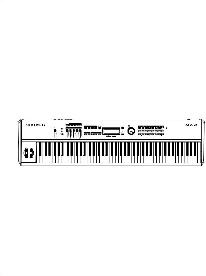
Main Features
The SP5 is a professional performance instrument. It boasts hundreds of preset excellent sounds (including the famous Triple Strike Stereo Concert Grand Piano) already on-board and ready to be played. It is also a capable MIDI controller ideally suited for controlling additional sound modules and as input to a sequencer.
The SP5 also features the Kurzweil’s KB3 organ simulator designed to emulate classic tone wheel organs like the Hammond B3.
Keyboard and Controllers
The SP5 has 88-key fully-weighted graded hammer keyboard action that provides you with a piano-like feel without adding excessive weight to the instrument. The array of physical controllers includes:
1-1

Introduction
Staying Current
• a pitch wheel
• a modulation wheel
• five assignable sliders (use the Shift button to select three different functions for each slider to control up to 15 parameters of your choosing).
• on the rear panel, three jacks for optional pedal controllers: two for switch pedals and a third for a continuous controller pedal–Pedal 1(Sustain), Pedal 2 and CC Pedal.
Pedals (Optional)
As described above, the SP5 has three jacks on the rear panel for optional pedal controllers. Two jacks for switch pedals, which are typically used to control two-state (i.e., on / off) parameters such as sustain, sostenuto, and mute Zone. The third jack is for a continuous control (or CC) pedal typically used to control multi-state (i.e., “continuous”) parameters such as filter frequency or LFO amount.
Note that switch pedals can be used to control continuous parameters just as continuous control pedals can be used to control two-state parameters.
Your Kurzweil dealer stocks the following pedals:
• |
FS-1 |
Standard box-shaped switch pedal |
• |
KFP-1 |
Single piano-style switch pedal |
• |
KFP-2S |
Double piano-style switch pedal unit (one stereo plug) |
• |
CC-1 |
Continuous pedal |
Staying Current
Be sure to check the Kurzweil Music Systems website at www.kurzweil.com for new documentation and software updates before using your new instrument.
Do You Have Everything?
Your SP5 package should contain the following in addition to your instrument:
• Power cable and 15V power adapter • Switch pedal
• USB cable (Type-A-to-Type-B)
• Musician’s Guide (this book)
If you don’t have all of these components, please to contact your Kurzweil / Young Chang dealer.
1-2

Getting Started
Before You Start…
Chapter 2
Getting Started
This chapter will help you hook up your SP5 to your sound system and MIDI system. If hooking up new gear is familiar to you, then simply read the following two sections in this chapter. If you need more information, then be sure to read this chapter in its entirety.
Before You Start…
Don’t connect anything until you make sure your SP5 is properly and safely situated. If your SP5 has been out in the cold, give it time to warm up to room temperature before starting it, since condensation may have formed inside.
Quick Start
Make Connections
1. Set the keyboard on a hard, flat, level surface.
2. Four adhesive-backed rubber feet are provided with your SP5. If you want to attach them to the bottom of the SP5 (recommended to prevent scratching your tabletop), carefully turn the keyboard over, remove the paper backing from the rubber feet and attach them near each corner all on the same level.
3. Connect the power cable to the adapter then plug the adapter’s DC power cord into your SP5. Finally, plug the power cable into the wall.
4. Make sure your sound system is at a safe volume level. Also make sure that the SP5’s
MASTER VOLUME slider (on the far left side of the front panel) is all the way down.
5. Plug in a pair of stereo headphones or run standard (1/4-inch) audio cables from your amplifier or mixer to the Audio Outputs on the SP5 (use the Left out for mono).
Balanced (“TRS” or “Stereo”) cables are recommended.
2-1
Getting Started
Start Up Details: The Rear Panel
Use Your SP5
1. Power up your SP5 first, and then raise the MASTER VOLUME slider. The SP5 starts up in Program Mode by default. Press one of the function buttons to the left of the display to switch Modes.
|
|
|
|
|
|
|
|
|
|
|
|
|
|
|
|
|
|
|
|
|
|
|
|
|
|
|
|
|
|
|
|
|
|
|
|
|
|
|
|
|
|
|
|
|
|
|
|
|
|
|
|
|
|
|
|
|
|
|
|
|
|
|
|
|
|
|
|
|
|
|
|
|
|
|
|
|
|
|
|
|
|
|
|
|
|
|
|
|
|
|
|
|
|
|
|
|
|
|
|
|
|
|
|
|
|
|
|
|
|
|
|
|
|
|
|
|
|
|
|
|
|
|
|
|
|
|
|
|
|
|
|
|
|
|
|
|
|
|
|
|
|
|
|
|
|
|
|
|
|
|
|
|
|
|
|
|
|
|
|
|
|
|
|
|
|
|
|
|
|
|
|
|
|
|
|
|
|
|
|
|
|
|
|
|
|
|
|
|
|
|
|
|
|
|
|
|
|
|
|
|
|
|
|
|
|
|
|
|
|
|
|
|
|
|
|
|
|
|
|
|
|
|
|
|
|
|
|
|
|
|
|
|
|
|
|
|
|
|
|
|
|
|
|
|
|
|
|
|
|
|
|
|
|
|
|
|
|
|
|
|
|
|
|
|
|
|
|
|
|
|
|
|
|
|
|
|
|
|
|
|
|
|
|
|
|
|
|
|
|
|
|
|
|
|
|
|
|
|
|
|
|
|
|
|
|
|
|
|
|
|
|
|
|
|
|
|
|
|
|
|
|
|
|
|
|
|
|
|
|
|
|
|
|
|
|
|
|
|
|
|
|
|
|
|
|
|
|
|
|
|
|
|
|
|
|
|
|
|
|
|
|
|
|
|
|
|
|
|
|
|
|
|
|
|
|
|
|
|
|
|
|
|
|
|
|
|
|
|
|
|
|
|
|
|
|
|
|
|
|
|
|
|
|
|
|
|
|
|
|
|
|
|
|
|
|
|
|
|
|
|
|
|
|
|
|
|
|
|
|
|
|
|
|
|
|
|
|
|
|
|
|
|
|
|
|
|
|
|
|
|
|
|
|
|
|
|
|
|
|
|
|
|
|
|
|
|
|
|
|
|
|
|
|
|
|
|
|
|
|
|
|
|
Alpha |
|
Wheel |
|
|
|
|
|
|
|
|
|
|
|
|
|||||||||||||
|
|
|
|
|
|
|
|
|
|
|
|
|
|
|
|
|
|
|
|
|
|
|
|
|
|
|
|
|
|
|
|
|
|
|
|
|
|
|
|
|
|
|
|
|
|
|
|
|
|
|
|
|
|
|
|
|
|
|||||||||||||||
|
|
|
|
|
|
|
|
|
|
|
|
|
|
|
|
|
|
|
|
|
|
|
|
|
|
|
|
|
|
|
|
|
|
|
|
|
|
|
|
|
|
|
|
|
|
|
|
|
|
|
|
|
|
|
||||||||||||||||||
|
|
|
|
|
|
|
|
|
|
|
|
|
|
|
|
|
|
|
|
|
|
|
|
|
|
|
|
|
|
|
|
|
|
|
|
|
|
|
|
|
|
|
|
|
|
|
|
|
|
|
|
|
|
|
|
|
|
|
|
|
|
|
|
|
||||||||
|
|
|
|
|
Mode & |
|
|
|
|
|
|
|
|
|
|
|
|
|
|
|
|
|
|
|
|
|
|
|
|
|
|
|
|
|
|
|
|
|
|
|
|
|
|
|
|
|
|
|
|
|
|
|
|
|
|
|
|
|
|
|
|
|||||||||||
|
|
|
|
|
|
|
|
|
|
|
|
Previous & Next |
|
|
|
|
|
|
|
|
|
|
|
|
|
|
|
Category |
|
|
|
|
|
|
||||||||||||||||||||||||||||||||||||||
|
|
|
|
|
Function |
|
|
|
|
|
|
|
|
|
|
|
|
|
|
|
|
|
|
|
|
|
|
|
|
|
|
|
|
|||||||||||||||||||||||||||||||||||||||
|
|
|
|
|
|
|
|
|
|
|
|
|
|
Buttons |
|
|
|
|
|
|
|
|
|
|
|
|
|
|
|
Buttons |
|
|
|
|
|
|
||||||||||||||||||||||||||||||||||||
|
|
|
|
|
Buttons |
|
|
|
|
|
|
|
|
|
|
|
|
|
|
|
|
|
|
|
|
|
|
|
|
|
|
|
|
|
|
|||||||||||||||||||||||||||||||||||||
|
|
|
|
|
|
|
|
|
|
|
|
|
|
|
|
|
|
|
|
|
|
|
|
|
|
|
|
|
|
|
|
|
|
|
|
|
|
|
|
|
|
|
|
|
|
|
|
|
|
|
|
|
|
|
|
|
|
|
|
|
||||||||||||
2. If you hear distortion, reduce the gain on your mixing board, or use the pad (a switch that decreases the input audio signal level, typically by 20dB) if it has one.
3. Scroll through the Programs using the Alpha Wheel, the Previous and Next buttons, or press a Category button, and try the SP5’s many sounds. Take note that initially there are no Programs in the User Category.
Start Up Details:
The Rear Panel
The power switch and all of the SP5’s connections take place on the rear panel.
Power |
DC Power |
USB Port |
MIDI Ports |
Pedal Jacks |
Headphones |
|
Switch |
|
Audio Jacks |
Jack |
|||
|
Jack |
|
|
|
|
|
The DC Power Jack
Use the DC power jack to connect the DC power supply.
The USB Port
Use the USB port to connect the SP5 to a computer in order to do the following:
2-2

Getting Started
Start Up Details:The Rear Panel
• Use the SP5 as a MIDI controller with a sequencer computer program. • Use the computer to manage the user data contents of the SP5.
• Update the software and sounds of the SP5.
Be sure to check the Kurzweil Music Systems website at www.kurzweil.com for new documentation and software updates before using your new instrument.
The MIDI (IN and OUT) Ports
Use the MIDI ports to communicate with other MIDI modules and controllers. The OUT port is the MIDI transmitting port, and the IN port is the MIDI receiving port.
The Pedal Jacks
Use the three pedal jacks to connect controller pedals to the SP5.
The Pedal 1 (Sustain) and Pedal 2 Jacks
Use the pedal jacks to connect switch pedals. A switch pedal is a physical controller typically used to control two-state (i.e., “on / off ”) parameters, such as sustain, sostenuto, and mute
Zone. Note that switch pedals can be used to control “continuous” parameters as well. It is possible to connect a dual switch pedal having a single stereo plug (Kurzweil KFP-2S available separately) into the Pedal 1 and Pedal 2 jacks. You would need a Y adapter to do this, see Connecting a Dual Switch Pedal on page 2-6.
The CC PEDAL Jack
Use the CC PEDAL jack to connect a continuous control (or CC) pedal. A CC pedal is a physical controller typically used to control multi-state (i.e., “continuous”) parameters such as filter frequency or LFO amount. Note that CC pedals can be used to control “on / off” parameters as well.
For more information on connecting pedals, see Connecting Pedals on page 2-5.
The Audio (LEFT/MONO and RIGHT) Jacks
Use the LEFT/MONO and RIGHT audio jacks to connect the SP5 to your audio system.
The Headphones Jack
Use the HEADPHONES jack to listen to the SP5 on stereo headphones. You will need a
1/4-inch-to-1/8-inch adapter in order to use headphones with a mini plug.
2-3
Getting Started
Connecting the Power Cable (Line Cord)
Connecting the Power Cable (Line Cord)
The SP5 runs on 15 volts DC power. If the power cord and 15V power adapter supplied with the SP5 does not match the AC power in your area: 100, 120, 230, or 240 volts at 50–60
Hz; contact your dealer to obtain the correct voltage converter and power cord. Plug the adapter into a wall outlet, and then connect the adapter to the DC power jack.
Connecting to Your Audio System
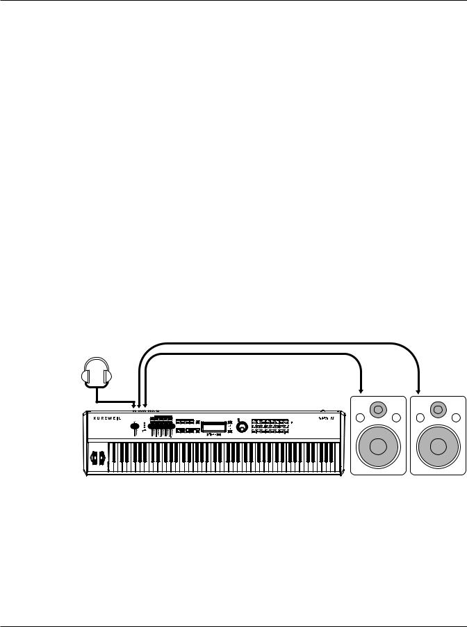
After you’ve turned down the level on your sound system, connect the SP5’s analog audio outputs to your sound system using a pair of stereo or mono audio cables. Mono cables will always work, but if you’re going into balanced inputs, use stereo cables for a better signal-to- noise ratio and a bit more volume: the SP5’s analog outputs are balanced.
You’ll find three 1/4-inch balanced audio output jacks on the rear panel. For now, connect one end of each audio cable to your mixing board or PA system inputs, and connect the other end to the jacks marked LEFT and RIGHT on the rear panel of the SP5. If you have only one input available, use the SP5’s Left output to get the full signal in mono. Use the jack marked HEADPHONES to listen to the SP5 on headphones. Note that when headphones are plugged in, sound still comes through the LEFT and RIGHT audio jacks.
SP5 connected to powered speakers and headphones
Headphones |
|
|
|
Right |
|
Left |
Right |
Audio |
Left |
||
Out |
|||
|
Audio |
Speaker |
Speaker |
|
Out |
SP5 |
|
|
|
|
2-4
Getting Started
Connecting Pedals
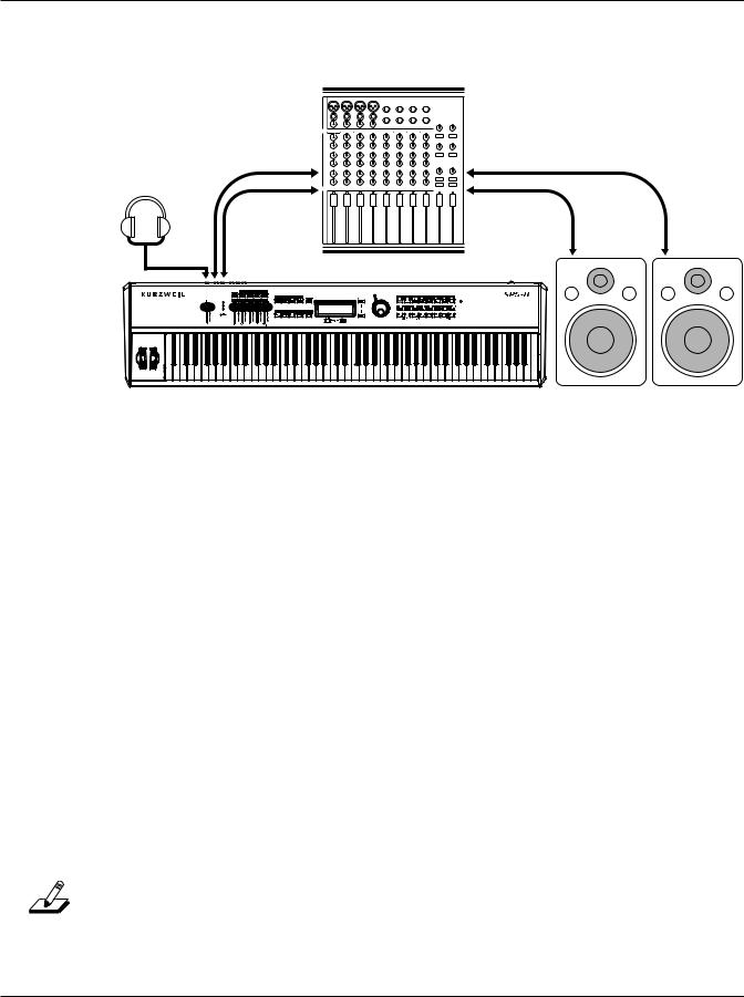
SP5 connected to a mixer, powered speakers and headphones
Right Mixer In |
Right Mixer Out |
Headphones |
Left Mixer Out |
Left Mixer In |
Right |
Left |
Left |
Right |
Audio |
|||
Out |
Audio |
Speaker |
Speaker |
|
Out |
|
|
|
|
SP5 |
|
Connecting Pedals
Plug your switch or continuous control pedals into the corresponding jacks on the SP5’s rear panel. We recommend using the Kurzweil pedals described in Pedals (Optional) on page 1-2, but you can use almost any switch or continuous control pedal that adheres to the following specifications (as most pedals do):
Switch pedals 1/4-inch tip-sleeve (mono) plug
Continuous Control (CC) 10-kOhm linear-taper potentiometer, 1/4-inch tip-
pedals |
ring-sleeve (stereo) plug with the wiper connected to |
|
the tip |
The pedals are independently assignable within each Zone of every setup. Here are the default settings for the three pedals you can use with the SP5:
Switch Pedal 1 |
Controller 64 |
(Sustain) |
Switch Pedal 2 |
Controller 66 |
(Sostenuto) |
CC Pedal |
Controller 11 |
(Expression / Volume) |
NOTE: Be sure not to step on the switch pedals when powering up your Stage Piano!
2-5
Getting Started
Connecting Pedals
Connecting a Switch Pedal
When a switch pedal is plugged into the Pedal 1 jack on the rear panel, a single switch pedal will, by default, act like a sustain pedal. The same is true for the Pedal 2 jack; in this case the single switch pedal will, by default, act like a sostenuto pedal. Of course this can be changed by programming, as described in Setup Mode on page 7-1.
If you use a third-party (non-Kurzweil) switch pedal, make sure it’s connected before you turn on your SP5. This ensures that the pedal will work properly (it might function in reverse—off when it’s down and on when it’s up—if you turn on your SP5 before plugging in the pedal). Similarly, don’t press any of your switch pedals while powering up, as the SP5 verifies each pedal’s orientation during power-up—if you’re pressing a pedal, you might cause it to work in reverse.
See Switch Pedal Problems on page 12-5 if you are having trouble with your switch pedal.
Connecting a Dual Switch Pedal
You can connect a dual switch pedal with a single stereo plug, such as the Kurzweil
KFP-2S, into the Pedal 1 and Pedal 2 jacks. You will need a Y adapter with a stereo 1/4-inch jack and two mono 1/4-inch plugs. Plug the Y adapter into the Pedal 1 and Pedal 2 jacks, then connect the dual switch pedal to the Y adapter. If the Sustain and Sostenuto functions are swapped, then swap the two mono plugs.
By default, the right pedal will control sustain as before and the left pedal will control the sostenuto function. If you’re not familiar with traditional piano technique, the sostenuto (center) pedal on a grand piano allows one to hold chords in the bass while continuing to play the melody without the latter notes sustaining. Any keys that are down when you depress the pedal will sustain when you let go of the keys, but new notes played afterward will not be sustained. Releasing the pedal puts things back to normal. Of course it can be programmed to do other functions as well.
Connecting a Continuous Control Pedal
A continuous control pedal can be very useful for controlling volume, vibrato, or other effect by foot. The Kurzweil CC-1 continuous control pedal will work best with the SP5, but it is also possible to use third-party continuous control pedals designed for synthesizers. Note that a volume pedal may or may not be satisfactory depending on how it is constructed.
See Continuous Control Pedal Problems on page 12-5 if you are having trouble with your continuous control pedal.
2-6
Getting Started
Connecting MIDI
Connecting MIDI
In addition to being a performance-suited musical instrument, the SP5 is a powerful, but intuitive and easy-to-use MIDI controller. For descriptions of how to customize your SP5 as a MIDI controller, and how to use its MIDI controller capabilities to their fullest potential, see Setup Mode on page 7-1.
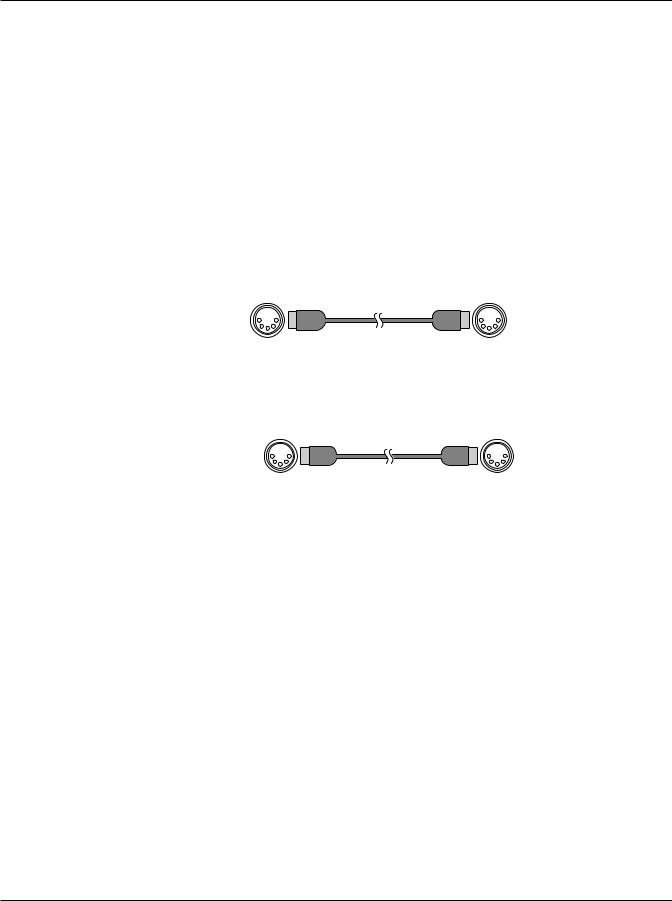
Basic MIDI Hookup
To use the SP5 as a MIDI controller for another sound module, use a MIDI cable to connect the MIDI port marked “OUT” to the MIDI input port of the module that you want to control.
SP5 |
Module |
Out |
In |
To control the SP5 using another MIDI controller, use a MIDI cable to connect the MIDI port marked “IN” to the MIDI output port of the controller that you will be using.
Controller |
SP5 |
Out |
In |
Connecting More Sound Modules
In order to connect multiple sound modules to be controlled by a single MIDI controller, your SP5 must either be (1) used as the controller or (2) be the last module in the MIDI daisy chain. This is because the SP5 does not include a THRU MIDI port; however, this simply means that the SP5 must be at the start or at the end of the MIDI daisy chain.
Using the SP5 as the controller, connect the MIDI OUT port to the MIDI IN port of the first module, and then connect that module’s MIDI THRU port to the input of the next module, and so on, until the last module is connected. The MIDI chain should end in the MIDI IN port of the last module.
2-7

Getting Started
Connecting MIDI
Scenario 1: SP5 as the MIDI controller
Module 1 MIDI Thru |
|
MIDI In |
Module 2 MIDI Thru |
|
MIDI In Last Module |
|
|
|
|
|
|
 MIDI In
SP5-8 |
MIDI Out |
|
Scenario 2: SP5 as the last module in the MIDI chain
Module 1 MIDI Thru |
MIDI In |
Module 2 MIDI Thru |
MIDI In
MIDI Out
Last Module |
SP5-8 |
MIDI In |
|
MIDI Controller
Connecting to a Computer Sequencer
To connect your SP5 to a computer as a MIDI controller, simply connect the SP5 to your computer using the provided cable. If you wish to use your own cable, make sure that it is a Type-A-to-Type-B USB cable (the USB port of the SP5 being Type B). By default, the SP5 will act as a MIDI controller (rather than a hard drive) when connected to a computer.
2-8
Features of the SP5
The Front Panel
Chapter 3
Features of the SP5
This chapter will help you familiarize yourself with the features of the SP5. Many of these features have both general functions and Mode-specific functions. For more in-depth descriptions of these features, refer to the chapters on the individual Modes.
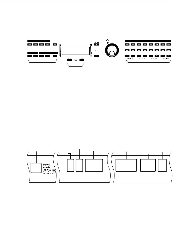
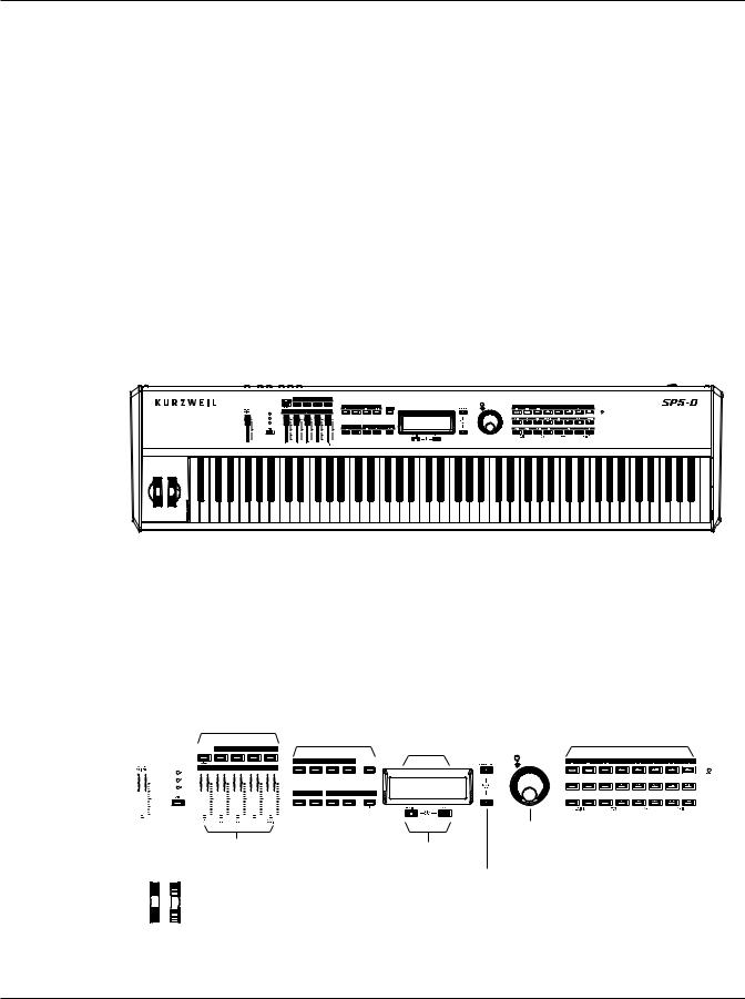
The Front Panel
All of the SP5’s controls, both musical and navigational, are on its front panel.
|
|
|
|
|
|
|
Zone & |
Mode & |
|
|
|
|
|
|
|
|
|
|
|
|
||||||||||
|
|
Programmable |
|
|
|
|
|
|
|
|
|
|
|
|
||||||||||||||||
|
Shift |
|
|
|
|
Buttons |
Function |
|
|
|
|
|
|
LCD |
Category |
KB3 |
||||||||||||||
|
Button |
|
|
|
|
|
|
|
|
|
|
Buttons |
|
|
Display |
|
Contrast |
Buttons |
LED |
|||||||||||
& LEDs |
|
|
|
|
|
|
|
|
|
|
|
|
|
|
|
|
|
|
|
|
|
|
|
|
|
|
||||
|
|
|
|
|
|
|
|
|
|
|
|
|
|
|
|
|
|
|
|
|
|
|
|
|
|
|
|
|
|
|
|
|
|
|
|
|
|
|
|
|
|
|
|
|
|
|
|
|
|
|
|
|
|
|
|
|
|
|
|
|
|
|
|
|
|
|
|
|
|
|
|
|
|
|
|
|
|
|
|
|
|
|
|
|
|
|
|
|
|
|
|
|
|
|
|
|
|
|
|
|
|
|
|
|
|
|
|
|
|
|
|
|
|
|
|
|
|
|
|
|
|
|
|
|
|
|
|
|
|
|
|
|
|
|
|
|
|
|
|
|
|
|
|
|
|
|
|
|
|
|
|
|
|
|
|
|
|
|
|
|
|
|
|
|
|
|
|
|
|
|
|
|
|
|
|
|
|
|
|
|
|
|
|
|
|
|
|
|
|
|
|
|
|
|
|
|
|
|
|
|
|
|
|
|
|
|
|
|
|
|
|
|
|
|
|
|
|
|
|
|
|
|
|
|
|
|
|
|
|
|
|
|
|
|
|
|
|
|
|
|
|
|
|
|
|
|
|
|
|
|
Alpha |
Assignable Sliders |
Value Buttons |
Wheel |
|
|
Pitch |
Channel/Parameter |
|
|
Buttons |
|
|
|
Modulation Wheels |
|
|
Pitch Mod |
(on left cheekblock) |
|
|
|
|
|
|
3-1
Features of the SP5
Pitch and Mod Wheels
Pitch and Mod Wheels
Pitch Wheel
The pitch wheel is the left most of the two wheels. It is spring-loaded, such that its center position is restored when it is not being used. That is because the pitch wheel is used for pitch-bending notes—its “off” position is in the center. Pushing the pitch wheel up bends the pitches of all notes up. Pulling the pitch wheel down bends the pitches of all notes down. You can program the bend amount for the Pitch Wheel using the Bend Range Down or
Bend Range Up parameter on Bend Range Down on page 8-11.
Mod Wheel
The mod wheel is the right most of the two wheels. Unlike the pitch wheel, the mod wheel is not spring loaded, and can be set to and left in any position between fully up and fully down. Typically, the mod wheel is assigned to a parameter that alters some aspect of the sound (e.g., vibrato, filter depth) when changed.
Real Time Control
3-2

Features of the SP5
Real Time Control
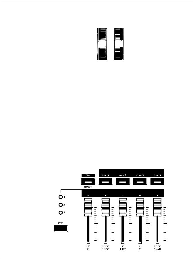
Sliders
The five sliders on the left of the front panel can be assigned to send MIDI continuous controller values. Each slider can independently control three separate functions giving you access to 15 MIDI continuous controllers. Think of this as three rows of five sliders. The
LEDs to the left of the sliders indicate what row is active. Press the Shift button to select a different row. For example, if you choose or this manual refers to Slider 8, LED 2 will be lit.
The sliders are arranged as follows:
• LED 1 lit, Sliders 1 – 5 • LED 2 lit, Sliders 6 – 10 • LED 3 lit, Sliders 11 – 15
If you select a KB3 Program, the first nine sliders act like tonewheel organ drawbars the remaining six sliders can perform other functions. The labeling below the sliders applies to the KB3 Programs.
Shift Button
The Shift button works in conjunction with the five sliders. Pressing the Shift button selects one of the three LEDs directly above it. A lit LED indicates the selected row.
Setup Zone Buttons
Pressing a Zone button will mute or unmute the zone. An active/unmuted Zone button has a lit LED. The LED of an inactive/muted Zone button is not lit.
Zones are the independent regions of the keyboard that make up a Setup, for additional information see About Zones on page 7-4.
Sw Button
The Sw button can be programmed to do a variety of functions. In Program Mode, the Sw button normally enables a pad/strings layer for some piano Programs. In Setup Mode, program the Sw button to send MIDI CC messages.
3-3
Features of the SP5
Mode & Function Buttons
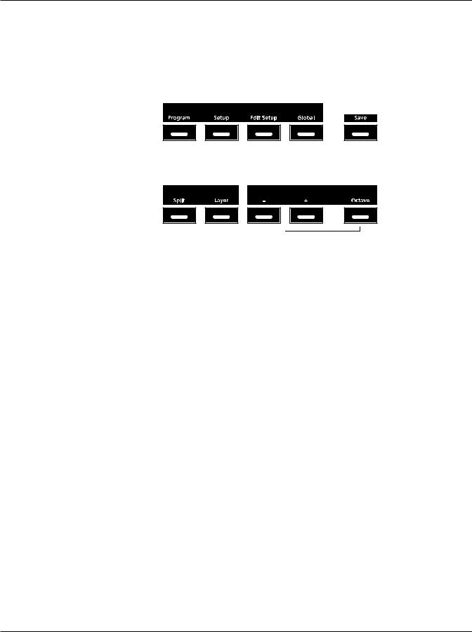
Mode & Function Buttons
The Mode buttons are located beneath the “Mode” label on the left side of the front panel.
Also in this area of the front panel are the Split and Layer Function buttons and the
Transpose and Save buttons.
Program Button
Pressing the Program button enters Program Mode (described in Program Mode on page 5-1 and, in further detail, in Program Mode on page 6-1). In Program Mode, you can select and play different sounds (or “Programs”). This button’s LED is illuminated when you are in
Program Mode. Program Mode is the default Mode—the SP5 starts up in this Mode.
Setup Button
Pressing the Setup button enters Setup Mode (described in The Operating Modes on page 5-1 and, in further detail, in Setup Mode on page 7-1). In Setup Mode, you can select different configurations (or “Setups”) of Programs, controller assignments, and MIDI channel assignments. This button’s LED is illuminated when you are in Setup Mode.
Edit Setup Button
Pressing the Edit Setup button enters Edit Setup Mode (described in The Operating Modes on page 5-1 and, in further detail, in Edit Setup Mode on page 8-1). In Edit Setup Mode, you can edit or create Setups. This button’s LED is illuminated when you are in Edit Setup Mode.
3-4

Features of the SP5
Mode & Function Buttons
Global Button
Pressing the Global button enters Global Mode (described in The Operating Modes on page 5-1 and, in further detail, in Global Mode on page 9-1). In Global Mode, you can edit parameters that control the entire SP5. These include tuning, transposition, and velocity and pressure (After Touch) sensitivity. Additionally, you can save or load User Programs and Setups to and from a computer connected to the SP5 via USB as well as perform a hard reset in this Mode. This button’s LED is illuminated when you are in Global Mode.
CAUTION: PERFORMING A HARD RESET WILL DELETE ALL USER PROGRAMS, USER SETUPS, AND GLOBAL SETTINGS.
Save Button
In Program Mode, pressing the Save button saves the changes to the current Program (sliders, Sw button, Mod Wheel) as a User Program, see Saving a User Program on page 6-11. In Setup Mode, pressing the Save button saves a copy of the current Setup. This is a copy of the original Setup and does not include the current state of the physical controllers (i.e., moved sliders, Mod Wheel, etc.), see Saving a User Setup on page 7-9. In Edit Setup Mode, pressing the Save button saves the currently edited Setup, see Saving a User Setup on page 8-18. The Save button’s LED is illuminated once you have made changes to the current Program or Setup.
Split Button
Pressing the Split button performs the Split Function. With the Split Function, you can split the keyboard in up to four Zones, and assign different Programs, MIDI settings, and transpositions to each Zone. The Split Function is described further in The Split Function on page 5-4.
Layer Button
Pressing the Layer button performs the Layer Function. With the Layer Function, you can layer the keyboard in up to four Zones, and assign different Programs, MIDI settings, and transpositions to each Zone. The Layer Function is described further in The Layer Function on page 5-4.
Transpose Buttons
In Program and Setup Modes, the top line of the display shows the current transposition value; zero is the default value. Pressing the Transpose + button will transpose the current Program or Setup up by one semitone; pressing the Transpose – button will transpose the current Program or Setup down by one semitone. Pressing both Transpose + and
3-5
Features of the SP5
Navigation
Transpose – buttons simultaneously will restore the current Program or Setup to having no transposition. If the transposition value is greater than zero, the Transpose + button’s LED will be lit. If the transposition value is less than zero, the Transpose – button’s LED will be lit.
If the Octave button is active, pressing the Transpose + or Transpose – buttons will transpose the current Program or Setup in octaves (+/– 12 semitones). The Octave button’s LED is lit when the button is active and remains lit until you press the button again to disable it.
The maximum transposition value is +/–36. If the Octave button is active and the current transposition value is greater than +24, pressing the Transpose + button will not increase the value as it would be out of range. If the Octave button is active and the current transposition value is less than –24, pressing the Transpose – button will not decrease the value as it would be out of range. The Transpose + and Transpose – button LEDs are lit if they have a transposition value other than zero.
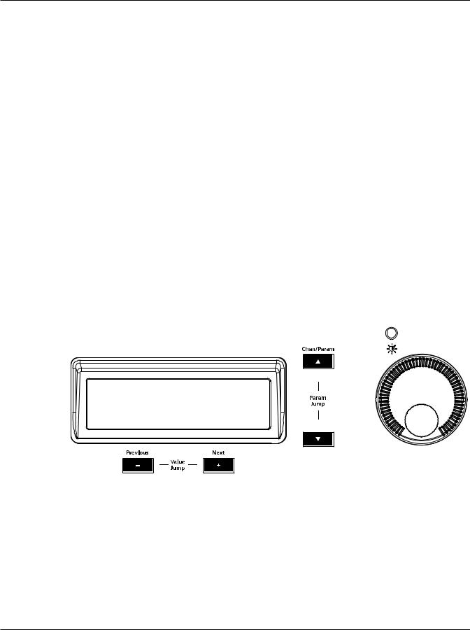
Navigation
The navigation section of the SP5’s front panel includes the alphanumeric display, Value buttons, Chan / Param buttons, and the Alpha Wheel. The display contrast knob is also located in this section above the Alpha Wheel.
The Display
The display shows two lines of text up to twenty characters in length. In Program and Setup Mode, the top line of the display shows the current Mode, MIDI transposition, and MIDI Channel (Program Mode only) and the bottom line shows the current Program or Setup ID number and name. In the other Modes—Edit Setup, Global, and System—the top line of the display shows the current Mode, Zone number (Edit Setup Mode only) and the current parameter number as well as the total the number of available parameters. The bottom line of the display shows the current parameter and value.
3-6

Features of the SP5
Navigation
NOTE: In the event a display line of text exceeds 20 characters, the text will scroll across the display marquee-style.
Previous (–) and Next (+) Value Buttons
Use the Next and Previous buttons to scroll through the list of items on the display. Pressing both the Next and Previous buttons simultaneously is called Value Jump and is referred to as the Value Jump buttons. Depending on the current Mode or operation, the Value Jump buttons can select the next Category or default Program, jump to specific intervals, and reset parameter values. For more information, see Value Jump on page 3-9
Chan / Param Buttons
In Program Mode, pressing the Chan / Param Up (̂) button will change the MIDI transmit channel from the current channel to the next one; pressing the Chan / Param Down (̌) button will change the MIDI transmit channel from the current channel to the previous one. When the highest or lowest MIDI transmit channel is reached, the list will wrap back to the last or first MIDI transit channel respectively. The top line of the display shows the current MIDI transmit channel.
In the other Modes—Edit Setup, Global, and System—pressing the Chan / Param buttons will scroll through the parameter list for the current Mode. As shown in the example below, the top line of the display shows the current parameter number / total number of parameters.
Gl obal |
4/30 |
FXSel:Perf |
|
NOTE: The Chan / Param Up (̂) and the Chan / Param Down (̌) buttons are not used in Setup Mode.
Alpha Wheel
Use the Alpha Wheel to scroll through the list of items on the display—turning the Alpha Wheel counter-clockwise will select the previous item and turning the Alpha Wheel
clockwise will select the next item. You can turn the Alpha Wheel slowly to change the value by one increment or turn it quickly to jump several increments.
Display Contrast Knob
You can adjust the display contrast by turning this small potentiometer knob.
3-7
 Loading...