

Page 1

SUMMIT 8800
Handbook
Flow Computer
Volume 3: Configuration
© KROHNE 08/2013 - MA SUMMIT 8800 Vol 3 R02 en
Page 2

SUMMIT 8800IMPRINT
All rights reserved. It is prohibited to reproduce this documentation, or any part thereof, without
the prior written authorisation of KROHNE Messtechnik GmbH.
Subject to change without notice.
Copyright 2013 by
KROHNE Messtechnik GmbH - Ludwig-KROHNE-Str. 5 - 47058 Duisburg (Germany)
2 www.krohne.com 08/2013 - MA SUMMIT 8800 Vol3 R02 en
Page 3

SUMMIT 8800
CONTENTS
1 About this book 12
1.1 Volumes ............................................................................................................................. 12
1.2 Content Volume 1 .............................................................................................................. 12
1.3 Content Volume 2 .............................................................................................................. 12
1.4 Content Volume 3 .............................................................................................................. 13
1.5 Information in this handbook ............................................................................................ 13
2 General Information 14
2.1 Software versions used for this guide ...............................................................................14
2.2 Terminology and Abbreviations ......................................................................................... 14
2.3 General Controls and Conventions ................................................................................... 15
2.4 ID Data Tree ....................................................................................................................... 16
2.4.1 Type of data ..............................................................................................................................17
2.4.2 Colour codes .............................................................................................................................18
2.4.3 ID Lookup ................................................................................................................................. 19
2.5 Specific Requirements for Meters and Volume Convertors ............................................. 19
2.5.1 Numbering formats ..................................................................................................................19
2.5.2 Alarms ...................................................................................................................................... 19
2.5.3 Optional consequences ............................................................................................................ 20
3 CONFIGURATOR SOFTWARE 21
4 DATE & TIME 23
4.1 Initial setting of date and time ......................................................................................... 23
4.2 SNTP Time Synchronisation .............................................................................................. 24
4.3 Manually change date and time ....................................................................................... 25
5 DATA LOGGING 27
5.1 Alarm and audit log security ............................................................................................. 27
5.2 Alarm log ........................................................................................................................... 28
5.3 Audit trail log ..................................................................................................................... 28
5.3.1 Audit log extension ................................................................................................................... 29
5.4 Data log .............................................................................................................................. 31
5.4.1 Access to data log .....................................................................................................................34
08/2013 - MA SUMMIT 8800 Vol3 R02 en
www.krohne.com
3
Page 4

SUMMIT 8800CONTENTS
6 DISPLAY AND WEB ACCESS 36
6.1 System pages .................................................................................................................... 36
6.2 User defined pages ........................................................................................................... 40
6.3 Display ............................................................................................................................... 40
6.3.1 Main menu & submenus .......................................................................................................... 41
6.3.2 Display page & items ...............................................................................................................44
6.3.3 Set the page type ...................................................................................................................... 45
6.4 Security / edit mode .......................................................................................................... 49
6.4.1 Users & submenus ...................................................................................................................49
6.4.2 Display page and items ............................................................................................................ 50
6.5 Supervisor Mode ............................................................................................................... 51
6.6 Alarm/Audit Security Configuration .................................................................................. 53
6.7 Mimic Diagrams ................................................................................................................ 53
6.7.1 Mimic diagram selection .......................................................................................................... 54
6.7.2 New mimic item .......................................................................................................................55
6.7.3 Configure mimic item ............................................................................................................... 56
6.8 Display templates .............................................................................................................. 64
6.8.1 Template selection ................................................................................................................... 65
6.8.2 New template item ................................................................................................................... 66
6.9 3D Graphs .......................................................................................................................... 74
6.9.1 Graph selection ........................................................................................................................76
6.9.2 Graph settings and options ...................................................................................................... 76
6.9.3 3D graph profile ........................................................................................................................78
6.10 Keyboard Configuration ...................................................................................................80
6.11 Default ............................................................................................................................. 82
6.12 Translation to local language .......................................................................................... 83
6.12.1 Importing a language file ....................................................................................................... 85
6.12.2 Change a language in Excel ................................................................................................... 86
6.13 Web access ...................................................................................................................... 88
7 REPORTING 89
7.1 Serial ticket printing .......................................................................................................... 90
7.1.1 Serial port settings ................................................................................................................... 90
7.1.2 Print jobs .................................................................................................................................. 91
7.1.3 Configure report .......................................................................................................................93
7.1.4 Format the items ...................................................................................................................... 94
7.1.5 Add statistics ............................................................................................................................ 96
7.1.6 Multiple pages .......................................................................................................................... 97
7.2 Ethernet reporting ............................................................................................................. 97
7.2.1 FTP protocol .............................................................................................................................98
7.2.2 SMTP E-mail protocol ..............................................................................................................98
7.2.3 Print jobs .................................................................................................................................. 99
7.2.4 Configure HTML report ..........................................................................................................102
7.2.5 Configure XML Reports .......................................................................................................... 109
4 www.krohne.com 08/2013 - MA SUMMIT 8800 Vol3 R02 en
Page 5

SUMMIT 8800
CONTENTS
7.3 Downloadable ID or active data reports .......................................................................... 117
7.3.1 Format the items .................................................................................................................... 118
7.3.2 Read a report ..........................................................................................................................119
8 COMMUNICATION 120
8.1 Type of protocols ............................................................................................................. 120
8.1.1 Standard protocol ................................................................................................................... 120
8.1.2 Meter protocols ......................................................................................................................120
8.1.3 Host protocols ........................................................................................................................120
8.2 Basic Communication setup ........................................................................................... 121
8.2.1 Port selection .........................................................................................................................121
8.2.2 Basic RS 232/485 serial port settings .................................................................................... 122
8.2.3 Basic Ethernet settings ......................................................................................................... 122
8.3 Modbus master ............................................................................................................... 123
8.3.1 Modbus master port selection and settings .......................................................................... 123
8.3.2 Modbus Master type ............................................................................................................... 124
8.3.3 Differential pressure meters .................................................................................................. 125
8.3.4 Ultrasonic and Coriolis meters .............................................................................................. 126
8.3.5 Provers ................................................................................................................................... 127
8.3.6 Gas chromatographs .............................................................................................................. 128
8.3.7 Redundancy master ............................................................................................................... 130
8.3.8 Custom Modbus master ......................................................................................................... 131
8.4 Modbus slave ................................................................................................................... 131
8.4.1 Modbus slave port selection and settings .............................................................................132
8.4.2 Modbus slave addresses ........................................................................................................ 135
8.4.3 Parameters .............................................................................................................................136
8.5 Enron Modbus ................................................................................................................. 139
8.5.1 Enron modbus settings: ......................................................................................................... 139
8.5.2 Create logs .............................................................................................................................140
8.5.3 Addressing scheme: .............................................................................................................. 143
8.5.4 Define Modbus alarms ........................................................................................................... 145
8.6 Pemex Modbus ................................................................................................................ 146
8.6.1 Logs ........................................................................................................................................ 146
8.6.2 Addressing scheme ................................................................................................................ 146
8.7 Instromet Ultrasonic protocol ......................................................................................... 147
8.8 Encoder protocol ............................................................................................................. 148
8.9 CTE Protocol .................................................................................................................... 149
8.10 DSfG Protocol ................................................................................................................ 152
8.11 SOAP protocol ................................................................................................................153
9 GENERAL INFORMATION 154
9.1 Unit Identification ............................................................................................................ 154
9.2 Date and time .................................................................................................................. 154
9.3 Translation .......................................................................................................................155
08/2013 - MA SUMMIT 8800 Vol3 R02 en
www.krohne.com
5
Page 6

SUMMIT 8800CONTENTS
9.4 Audit log ........................................................................................................................... 155
9.5 Settings ............................................................................................................................ 155
9.6 Product information ........................................................................................................ 156
9.7 Calculation code .............................................................................................................. 156
9.8 Factory acceptance test check ........................................................................................ 157
9.9 Security configuration ..................................................................................................... 159
9.10 ID report......................................................................................................................... 161
9.11 Maintenance .................................................................................................................. 161
9.12 Formatting ..................................................................................................................... 162
9.13 Customs strings ............................................................................................................ 163
9.14 Minimum & maximum ID’s ........................................................................................... 164
9.15 Redundancy ................................................................................................................... 166
9.16 Watchdog ....................................................................................................................... 166
9.17 Run-switching ............................................................................................................... 166
9.18 SOAP .............................................................................................................................. 166
9.19 Modbus time-out ........................................................................................................... 166
9.20 Modbus alarms .............................................................................................................. 167
9.21 CTE Configuration ......................................................................................................... 167
10 APPENDIX 1: SOFTWARE VERSIONS 168
10.1 Versions/ Revisions ....................................................................................................... 168
10.2 Current versions ............................................................................................................ 168
10.2.1 Latest version 0.35.0.0 .........................................................................................................168
10.2.2 Approved version MID2.4.0.0 ................................................................................................ 169
11 APPENDIX 2: TABLE OF LEGALLY-RELEVANT PARAMETERS 170
12 APPENDIX 3: MODBUS COMMUNICATION PROTOCOL 171
12.1 Number formats ............................................................................................................ 171
6 www.krohne.com 08/2013 - MA SUMMIT 8800 Vol3 R02 en
Page 7

SUMMIT 8800
Figure 1 Example ID Tree ..................................................... 17
Figure 2 ID lookup ........................................................... 19
Figure 3 Configurator option selections ......................................... 21
Figure 4 Application firmware version ........................................... 21
Figure 5 Main Configurator display ............................................. 22
Figure 6 Date & time and contract time selection ................................. 23
Figure 7 SNTP Date & time general settings ..................................... 24
Figure 8 SNTP Date & time unicast settings ...................................... 25
Figure 9 SNTP Date & time broadcast settings .................................... 25
Figure 10 Manual Date & time settings .......................................... 26
Figure 11 Manual Date & time adjustment ....................................... 26
Figure 12 Display security window .............................................. 27
Figure 13 Alarm log .......................................................... 28
Figure 14 Audit trail log ....................................................... 29
Figure 15 Audit log extension .................................................. 30
Figure 16 Audit log select alarms ............................................... 30
Figure 17 Audit log select variables ............................................. 31
Figure 18 Audit log options .................................................... 31
Figure 19 Data logging ........................................................ 32
Figure 20 Data log select variables ............................................. 32
Figure 21 Data log settings .................................................... 33
Figure 22 Data log statistics ................................................... 33
Figure 23 Data log local log numbers ........................................... 34
Figure 24 Data log ID’s for FTP printing with log record selection .................... 35
Figure 25 Data log ID’s for modbus with index selection ............................ 35
Figure 26 Display, set the correct engineering units ............................... 36
Figure 27 Alarm and audit log .................................................. 37
Figure 28 Edit mode and system information ..................................... 38
Figure 29 Settings, display settings and touchscreen calibration .................... 39
Figure 30 Display main page ................................................... 40
Figure 31 Configurator main menu & submenu ................................... 41
Figure 32 Display main menu & submenu ........................................ 41
Figure 33 New menu, select template ........................................... 42
Figure 34 Edit a menu item .................................................... 43
Figure 35 Bit map editor ...................................................... 43
Figure 36 Import bit map ...................................................... 44
Figure 37 Configure display page ............................................... 44
Figure 38 Display item details ................................................. 45
Figure 39 Display page based on 8 centre template ................................ 46
Figure 40 Display page based on VU template .................................... 46
Figure 41 Display page based on a mimic ........................................ 47
Figure 42 Display page based on a mimic ........................................ 47
Figure 43 Display page based on log data (list). . . . . . . . . . . . . . . . . . . . . . . . . . . . . . . . . . . . 47
Figure 44 Display page based on log data (Graph) ................................. 48
Figure 45 Display page based on a X-Y-Z graph ................................... 48
Figure 46 Configurator security window ......................................... 49
Figure 47 Configurator users & submenus ....................................... 49
Figure 48 Summit users & submenu ............................................ 50
Figure 49 Edit users .......................................................... 50
Figure 50 Same page in normal and in supervisor mode ........................... 51
Figure 51 Setup supervisor mode .............................................. 52
Figure 52 Summit supervisor mode login and logout .............................. 53
Figure 53 Mimic display definition .............................................. 54
Figure 54 Create a mimic display canvas ........................................ 54
Figure 55 New mimic display .................................................. 55
Figure 56 Create a mimic display canvas ........................................ 55
Figure 57 New mimic item and right mouse click on an item ........................ 56
CONTENTS
08/2013 - MA SUMMIT 8800 Vol3 R02 en
www.krohne.com
7
Page 8

SUMMIT 8800TABLE OF FIGURES
Figure 58 Mimic item configure colour .......................................... 58
Figure 59 Mimic item colour palette ............................................ 59
Figure 60 Mimic item configure an alarm and warning ............................. 60
Figure 61 Mimic item configure image ........................................... 60
Figure 62 Mimic item edit image and crop/stretch image ........................... 61
Figure 63 Mimic item configure operators ....................................... 62
Figure 64 Mimic item configure condition ........................................ 62
Figure 65 Mimic item configure text ............................................. 63
Figure 66 Mimic item configure variable ......................................... 63
Figure 67 Mimic item configure format for a variable and for a button ................ 64
Figure 68 Mimic item configure format for a variable and for a button ................ 64
Figure 69 Display templates ................................................... 65
Figure 70 Create a template ................................................... 65
Figure 71 New display template ................................................ 66
Figure 72 Create a mimic display canvas ........................................ 66
Figure 73 A display template and right mouse click on item ........................ 66
Figure 74 Move and re-size an item ............................................. 67
Figure 75 Template: variable configuration and Summit screen ..................... 68
Figure 76 Template: VU meter configuration and Summit screen .................... 68
Figure 77 Template: VU meter configure limits and colours ......................... 69
Figure 78 Template: vertical bar graph configuration and Summit screen ............. 70
Figure 79 Template: horizontal bar graph configuration and Summit screen .......... 70
Figure 80 Template: two signed bar graphs for the configurator and Summit screen .... 70
Figure 81 Template: bar graphs configure limits and colours ....................... 71
Figure 82 Template: trend configuration and Summit screen ........................ 72
Figure 83 Template: trend configure limits and colours ............................ 73
Figure 84 3D graph settings ................................................... 74
Figure 85 Summit 3D graph; X-Y-Z and X-Y chart example. . . . . . . . . . . . . . . . . . . . . . . . . . 75
Figure 86 Create a mimic display canvas ........................................ 76
Figure 87 New graph display .................................................. 76
Figure 88 New graph range settings ............................................ 76
Figure 89 New graph colour settings ............................................ 77
Figure 90 New graph options .................................................. 77
Figure 91 New graph profile ................................................... 78
Figure 92 Graph profile, Top ................................................... 78
Figure 93 Graph profiles for value and ID’s ....................................... 79
Figure 94 Graph profile, enter the X-Y pair for one line ............................. 79
Figure 95 Display keyboard customisation and use ................................ 80
Figure 96 Create a keyboard ................................................... 80
Figure 97 New display keyboard ................................................ 81
Figure 98 Display keyboard, key definition ....................................... 81
Figure 99 Display French keyboard in configuration and on the Summit .............. 82
Figure 100 Display default configuration ......................................... 82
Figure 101 Display default settings ............................................. 82
Figure 102 Translation to Spanish .............................................. 83
Figure 103 Selection of Spanish ................................................ 84
Figure 104 Create a language .................................................. 84
Figure 105 Name and search a language ........................................ 84
Figure 106 Language configuration ............................................. 85
Figure 107 Import a language file .............................................. 86
Figure 108 Select language to be exported ....................................... 86
Figure 109 Converting a language file in Excel .................................... 87
Figure 110 Save as an Excel language CSV file .................................... 87
Figure 111 Web access enabled ................................................ 88
Figure 112 Web access. . . . . . . . . . . . . . . . . . . . . . . . . . . . . . . . . . . . . . . . . . . . . . . . . . . . . . . . 88
Figure 113 Web access setup for Ethernet port 1 .................................. 89
Figure 114 Ticket printer ...................................................... 90
8 www.krohne.com 08/2013 - MA SUMMIT 8800 Vol3 R02 en
Page 9

SUMMIT 8800
Figure 115 Ticket printer settings .............................................. 91
Figure 116 Ticket printer print jobs ............................................. 91
Figure 117 Ticket printer print jobs ............................................. 92
Figure 118 Ticket printer print jobs ............................................. 92
Figure 119 Ticket printer print conditions ........................................ 92
Figure 120 Configure reports .................................................. 93
Figure 121 Variable and log data ID selection ..................................... 94
Figure 122 Zoom function ..................................................... 94
Figure 123 Variable item options with formatting details ........................... 94
Figure 124 Data log item options with changed time period and format ............... 95
Figure 125 Data log item Select statistics ....................................... 96
Figure 126 Page selection ..................................................... 97
Figure 127 Ethernet port configuration ......................................... 98
Figure 128 Ethernet port FTP configuration . . . . . . . . . . . . . . . . . . . . . . . . . . . . . . . . . . . . . . 98
Figure 129 Ethernet port SMTP configuration .................................... 99
Figure 130 Ethernet printjob configuration ...................................... 100
Figure 131 Ethernet reporting print jobs ......................................... 100
Figure 132 Ethernet reporting print conditions ................................... 101
Figure 133 Ethernet reporting select printer and print data ......................... 101
Figure 134 Ticket printer print jobs ............................................. 102
Figure 135 Configure Ethernet reports .......................................... 102
Figure 136 Configure Ethernet reports, select report .............................. 103
Figure 137 Configure Ethernet reports, format the paper .......................... 103
Figure 138 Configure Ethernet reports, format the report data ...................... 103
Figure 139 Select items ....................................................... 104
Figure 140 Select a text ....................................................... 104
Figure 141 Select a variable from a list .......................................... 104
Figure 142 Select log data from a list ........................................... 105
Figure 143 Select alarm log data ............................................... 105
Figure 144 Select audit log data ............................................... 106
Figure 145 Select an image ................................................... 106
Figure 146 Create a graph ..................................................... 107
Figure 147 Format an item .................................................... 107
Figure 148 Data log item Select statistics ....................................... 108
Figure 149 Configure Ethernet reports, page selection ............................. 109
Figure 150 XML report configuration ............................................ 110
Figure 151 Configure Ethernet reports, select xml report .......................... 110
Figure 152 Configure Ethernet reports, select file name ........................... 111
Figure 153 Configure Ethernet reports, xml report data ............................ 111
Figure 154 Configure Ethernet reports, xml report data ............................ 112
Figure 155 Begin XML tag window and result ..................................... 112
Figure 156 End XML tag normal and error result .................................. 112
Figure 157 ID configuration window and result ................................... 113
Figure 158 Log data configuration window and results ............................. 114
Figure 159 Audit log data configuration window ................................... 115
Figure 160 Format an item .................................................... 117
Figure 161 ID report configuration .............................................. 117
Figure 162 Configure ID reports, select report .................................... 118
Figure 163 Configure ID reports, report data ..................................... 118
Figure 164 Format an item .................................................... 119
Figure 165 Read an ID report .................................................. 119
Figure 166 Communication board and port selection .............................. 121
Figure 167 Serial port type selection and a typical setting .......................... 122
Figure 168 Ethernet configuration page ......................................... 122
Figure 169 Example Modbus and Modbus over TCP/IP master port settings ........... 123
Figure 170 Modbus device selection ............................................ 124
Figure 171 Modbus Bristol 3808 MVT ............................................ 125
TABLE OF FIGURES
08/2013 - MA SUMMIT 8800 Vol3 R02 en
www.krohne.com
9
Page 10

SUMMIT 8800TABLE OF FIGURES
Figure 172 Modbus device selection ............................................ 126
Figure 173 Modbus master, selection of gas coriolis meter ......................... 127
Figure 174 Modbus master GC device settings .................................... 129
Figure 175 Modbus master GC component settings ................................ 130
Figure 176 Modbus redundancy master ......................................... 130
Figure 177 LUA script page .................................................... 131
Figure 178 Example RS232/485 Modbus serial and TCP/IP port settings .............. 132
Figure 179 Modbus slave enable timeout ........................................ 133
Figure 180 Modbus slave timeout settings ....................................... 133
Figure 181 Modbus slave log settings ........................................... 134
Figure 182 Modbus slave address offset settings ................................. 134
Figure 183 Modbus slave register configuration .................................. 135
Figure 184 Modbus slave ID lists: variables, log data, status bits .................... 135
Figure 185 Modbus slave registers ............................................. 136
Figure 186 Modbus slave im- and export ........................................ 137
Figure 187 Modbus serial settings .............................................. 138
Figure 188 Modbus register parameter functions ................................. 138
Figure 189 Modbus parameter settings .......................................... 139
Figure 190 Enron modbus serial settings ........................................ 140
Figure 191 Enron event log .................................................... 141
Figure 192 Enron daily log ..................................................... 142
Figure 193 Enron hourly log ................................................... 143
Figure 194 Enron modbus log selections. . . . . . . . . . . . . . . . . . . . . . . . . . . . . . . . . . . . . . . . . 144
Figure 195 Enron modbus log addressing ........................................ 144
Figure 196 Enron modbus addressing ........................................... 145
Figure 197 Enron Modbus alarms .............................................. 146
Figure 198 Figure 198 Instromet protocol serial settings .......................... 147
Figure 199 Encoder setting .................................................... 148
Figure 200 CTE protocol hardware setting ....................................... 149
Figure 201 CTE protocol setting ................................................ 150
Figure 202 CTE protocol setting ................................................ 150
Figure 203 CTE protocol variables .............................................. 151
Figure 204 CTE protocol log data ............................................... 151
Figure 205 Figure 205 DSfG block diagram ....................................... 152
Figure 206 Ethernet configuration page ......................................... 153
Figure 207 Soap user configuration ............................................. 153
Figure 208 General unit identifier .............................................. 154
Figure 209 General settings ................................................... 155
Figure 210 Calculation code and help ........................................... 157
Figure 211 Configure a FAT check .............................................. 158
Figure 212 User authorization and security configuration selection .................. 160
Figure 213 Read and modify a secure configuration in partial mode .................. 160
Figure 214 Maintenance configuration .......................................... 161
Figure 215 Formatting configuration ............................................ 162
Figure 216 Configure string ID’s and resulting variables ........................... 163
Figure 217 Configure string ID’s formatting ...................................... 164
Figure 218 Min/max ID setting and resulting variables ............................. 165
10 www.krohne.com 08/2013 - MA SUMMIT 8800 Vol3 R02 en
Page 11

SUMMIT 8800
IMPORTANT INFORMATION
KROHNE Oil & Gas pursues a policy of continuous development and product improvement. The
Information contained in this document is, therefore subject to change without notice. Some
display descriptions and menus may not be exactly as described in this handbook. However, due
the straight forward nature of the display this should not cause any problem in use.
To the best of our knowledge, the information contained in this document is deemed accurate
at time of publication. KROHNE Oil & Gas cannot be held responsible for any errors, omissions,
inaccuracies or any losses incurred as a result.
In the design and construction of this equipment and instructions contained in this handbook,
due consideration has been given to safety requirements in respect of statutory industrial regulations.
ABOUT THIS HANDBOOK
01
Users are reminded that these regulations similarly apply to installation, operation and maintenance, safety being mainly dependent upon the skill of the operator and strict supervisory
control.
08/2013 - MA SUMMIT 8800 Vol3 R02 en
www.krohne.com
11
Page 12

1. About this book
1.1 Volumes
This is Volume 3 of 3 of the SUMMIT 8800 Handbook:
Volume 1
Volume 1 is targeted to the electrical, instrumentation and maintenance engineer
This is an introduction to the SUMMIT 8800 flow computer, explaining its architect and layout providing the user with familiarity and the basic principles of build. The volume describes the
Installation and hardware details, its connection to field devices and the calibration.
The manual describes the operation via its display, its web site and the configuration software.
Also the operational functional of the Windows software tools are described, including the configurator, the Firmware wizard and the display monitor.
Volume 2
Volume 2 is targeted to the metering software configuration by a metering engineer.
The aim of this volume is to provide information on how to configure a stream and the associated hardware.
The handbook explains the configuration for the different metering technologies, including meters, provers, samplers, valves, redundancy etc.. A step by step handbook using the Configurator
software, on the general and basic setup to successfully implement flow measurement based on
all the applications and meters selections within the flow computer.
SUMMIT 8800ABOUT THIS HANDBOOK01
Volume 3
Volume 3 is targeted to the software configuration of the communication to the outside world.
The manual covers all advance functionality of the SUMMIT 8800 including display configuration,
reports, communication protocols, remote access and many more advance options.
1.2 Content Volume 1
Volume 1 concentrates on the daily use of the flow computer
• Chapter 2: Basic functions of the flow computer
• Chapter 3: General information on the flow computer
• Chapter 4: Installation and replacement of the flow computer
• Chapter 5: Hardware details on the computer, its components and boards
• Chapter 6: Connecting to Field Devices
• Chapter 7: Normal operation via the touch screen
• Chapter 8: How to calibration the unit
• Chapter 9: Operation via the optional web site
• Chapter 10: Operational functions of the configuration software, more details in volume 2
• Chapter 11: How to update the firmware
• Chapter 12: Display monitor software to replicate the SUMMIT 8800 screen on a PC and make
screen shots
1.3 Content Volume 2
Volume 2 concentrates on the software for the flow computer.
• Chapter 2: General information on the software aspects of the flow computer
• Chapter 3: Details on metering principles
• Chapter 4: Basic functions of configurator
• Chapter 5: Configuration of the hardware of the boards
• Chapter 6: Stream configuration
• Chapter 7: Run switching
• Chapter 8: Watchdog
12 www.krohne.com 08/2013 - MA SUMMIT 8800 Vol3 R02 en
Page 13

SUMMIT 8800
• Chapter 9: Configure a station
• Chapter 10: Configure a prover or master meter
• Chapter 11: Configure valves
• Chapter 12: Configure a sampler
• Chapter 13: Set-up batching
• Chapter 14: Set two flow computers in redundant configuration
1.4 Content Volume 3
Volume 3 concentrates on the configuration of the SUMMIT 8800
• Chapter 3; Configurator software
• Chapter 4: Date & Time
• Chapter 5: Data Logging
• Chapter 6: Display and web access
• Chapter 7: Reporting
• Chapter 8: Communication
• Chapter 9: General Information
1.5 Information in this handbook
ABOUT THIS HANDBOOK
01
The information in this handbook is intended for the integrator who is responsible to setup and
configure the SUMMIT 8800 flow computer for Liquid and or Gas and or Steam application:
Integrators (hereafter designated user) with information of how to install, configure, operate and
undertake more complicated service tasks.
This handbook does not cover any devices or peripheral components that are to be installed and
connected to the SUMMIT 8800 it is assumed that such devices are installed in accordance with
the operating instructions supplied with them.
Disclaimer
KROHNE Oil & Gas take no responsibility for any loss or damages and disclaims all liability for
any instructions provided in this handbook. All installations including hazardous area installations are the responsibility of the user, or integrator for all field instrumentation connected to
and from the SUMMIT 8800 Flow computer.
Trademarks
SUMMIT 8800 is a trade mark of KROHNE Oil & Gas.
Notifications
KROHNE Oil & Gas reserve the right to modify parts and/or all of the handbook and any other
documentation and/ or material without any notification and will not be held liable for any damages or loss that may result in making any such amendments.
Copyright
This document is copyright protected.
KROHNE Oil & Gas does not permit any use of parts, or this entire document in the creation of
any documentation, material or any other production. Prior written permission must be obtained
directly from KROHNE Oil & Gas for usage of contents. All rights reserved.
Who should use this handbook?
This handbook is intended for the integrator or engineer who is required to configure the flow
computer for a stream including devices connected to it.
Versions covered in this handbook
All Versions
08/2013 - MA SUMMIT 8800 Vol3 R02 en
www.krohne.com
13
Page 14

2. General Information
2.1 Software versions used for this guide
This handbook is based on the software versions as mentioned in Appendix 1: software versions
2.2 Terminology and Abbreviations
AGA American Gas Association
API American Petroleum Institute
Communication board Single or dual Ethernet network board
Configurator Windows software tool to configure and communicate to the SUMMIT 8800
CP Control Panel
CPU Central Processing Unit
CRC32 Cyclic Redundancy Check 32 bits. Checksum to ensure validity of information
FAT Factory Acceptance Test
FDS Functional Design Specification
HMI Human-Machine Interface
HOV Hand Operated Valve
I/O Input / Output
ISO International Standards Organization
KOG KROHNE Oil and Gas
KVM Keyboard / Video / Mouse
MOV Motor Operated Valve
MSC Metering Supervisory Computer
MUT Meter Under Test
Navigator 360 optical rotary dial
PC Personal Computer
PRT Platinum Resistance Thermometers
PSU Power Supply Unit
PT Pressure Transmitter
Re-try Method to repeat communication a number of times before giving an alarm
RTD: Resistance Temperature Device
Run: Stream/Meter Run
SAT Site Acceptance Test
SUMMIT 8800 Flow computer
Timestamp Time and date at which data is logged
Time-out Count-down timer to generate an alarm if software stopped running
TT Temperature Transmitter
UFC Ultrasonic Flow Converter
UFM Ultrasonic Flow Meter
UFP Ultrasonic Flow Processor (KROHNE flow computer )
UFS Ultrasonic Flow Sensor
VOS Velocity of Sound
ZS Ball detector switch
XS Position 4-way valve
XV Control 4-way valve
SUMMIT 8800GENERAL INFORMATION02
14 www.krohne.com 08/2013 - MA SUMMIT 8800 Vol3 R02 en
Page 15

SUMMIT 8800
2.3 General Controls and Conventions
In the configurator several conventions are being used:
Numeric Data Entry Box
Clear background, black text, used for entering Numeric Data, a value must be entered here
Optional: Coloured background, black text used for entering optional Numeric Data. If no value
is entered then right click mouse key and select Invalidate, box will show and no number will be
entered.
An invalid Number will be shown on the SUMMIT 8800 display as “---------“ and is read serially
as 1E+38
Pull-Down Menu
Select a function or option from a list functions or options
GENERAL INFORMATION
02
Icon
Selects a function or a page.
Tabs
Allows an individual page, sub-page or function to be selected from a series of pages, sub-pages or functions.
Expanded item Fewer items shown.
Non Expanded item +
More items shown.
Option Buttons
Red cross means OFF or No
Green tick means ON or Yes
Data Tree
Items from the Data Tree can be either selected or can be “Dragged and dropped” from the Tree
into a selection box; for example when setting up a logging system or a Modbus list, etc.
Yellow Data circle means Read Only. Red data circle means Read and Write.
Hover over
Hold the cursor arrow over any item, button or menu, etc. Do not click any mouse button, the
item will be lightly highlighted and information relating to the selection will be illustrated.
Grey Text
Indicates that this item has no function or cannot be entered in this particular mode of the system. The data is shown for information purposes only.
Help Index
Display information that assists the user in configuration.
Naming convention of Variables
In the KROHNE SUMMIT 8800 there are variables used with specific naming.
This naming is chosen to identify a variable and relate it to the correct stream.
08/2013 - MA SUMMIT 8800 Vol3 R02 en
www.krohne.com
15
Page 16

SUMMIT 8800GENERAL INFORMATION02
The most complex variable is explained below and this explanation can be used to interpret all
the other variable names.
Example: + ph uVN . 1
+ Positive (+) or negative (-)
Ph Previous (P) or Current (C) period
Pqh – previous 15 minutes
Ph – previous hour
Pd – previous Day
Pm – previous month
Pq – previous quarter of a year
Cqh – current 15 minutes
Ch – current hour
Cd – current Day
Cm – current month
Cq – current quarter of a year
u Type of totals
u – Unhaltable, counts always
m – Maintenance, counts when maintenance is active (optional)
n – Normal, fiscal counters during normal operation
e – Error, fiscal counters with an accountable error
t1 –> t4 – Tarif , fiscal counters based on fiscal thresholds
VN Type of flow
VPulses, pulses counted
Vline, gross volume flow
Vmon, monitored grass volume flow
Vbc (p/t) pressure and temperature corrected gross volume flow
Vbc, linearization corrected (Vbc(p/t))gross volume flow
VN, Normalized volume flow
VN(net), Nett normalized flow
VM, Mass flow
VE, Energy flow
VCO2, carbon dioxide flow
1 Stream/ Run number
2.4 ID Data Tree
When selecting parameters and options in the Configurator software, the user will be presented
with a tree structure for instance:
16 www.krohne.com 08/2013 - MA SUMMIT 8800 Vol3 R02 en
Page 17
SUMMIT 8800
GENERAL INFORMATION
02
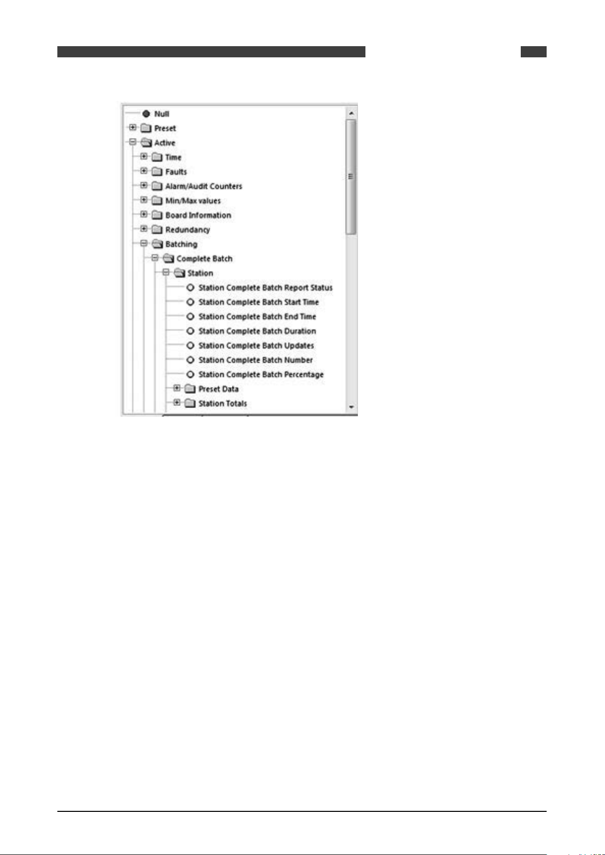
Figure 1 Example ID Tree
This is referred to as the ID tree which, depending on its context, includes folders and several
parameters:
2.4.1 Type of data
The rest of this chapter will explain the folders available, the type of selection within the folder
and any other corresponding data.
Preset Data
Essential to the configuration of the flow computer. Typical data would be keypad values, operating limits, equation selection, calibration data for Turbines and Densitometers and Orifice
plates.
This data would be present in a configuration report, and enables you to see what the flow computer is configured to do.
Used for validation and will form the Data Checksum (visible on the System Information Page).
E.g., if a data checksum changes, the setup of the flow computer has changed and potentially
calculating different results to what is expected.
Typically configured and left alone, only updated after validation e.g. every 6 month / 1 year.
Active Data
These values cover inputs to the flow computer. E.g. from GC, pressure & temperature transmitters, meters etc..
Also Values calculated in the flow computer. E.g. Flow rates, Z, Averages, Density etc..
Local Data
Data that an operator can change locally to perform maintenance tasks. E.g., turn individual
transmitters off without generating alarms. Setting Maintenance mode or Proving Mode.
08/2013 - MA SUMMIT 8800 Vol3 R02 en
www.krohne.com
17
Page 18

Totals
Totals for the streams and station.
Contents of this folder are stored in the non-volatile RAM and are protected using the battery.
Custom
User defined variables.
Allows calculations, made in a LUA script, to be used in a configuration.
For details, see volume 3.
2.4.2 Colour codes
With each parameter and option, there are corresponding coloured dots that represent the access and status of the particular selection.
General ID tree
Please note that it might be possible to change the values via the screen
SUMMIT 8800GENERAL INFORMATION02
Red Dot Data is Read/Write and can be changed over Modbus.
Yellow Dot Data is Read-Only and cannot be changed over Modbus
90% of the data will be Read Only, but items such as Serial Gas Compositions, Time/Date, MF
are commonly written over Modbus.
NOTE: Although the ID may be read/write, the security setting determines whether the ID indeed
can be written.
Alarm Tree
The alarm tree is built of all the registers that hold alarm data. Alarm registers are 32-bit integers, where each bit represents a different alarm.
Red Dot Represents an accountable alarm visible on the alarm list.
Dark Blue Dot Represents a non-accountable alarm visible on the alarm list.
Orange Dot Represents a warning visible on the alarm list.
Light Blue Dot Represents a status alarm, not visible on the alarm list.
Black/Grey Dot Represents a hard- or software fault alarm visible on the alarm list.
An example of typical usage would be the General Alarm Register. This is a 32 bit register that
indicates up to 32 different alarms in the flow computer. This will contain Status Alarms, for example, 1 bit will indicate if there is a Pressure alarm or not. If the Pressure Status bit is set the
user will know that there is a problem with the Pressure.
This should be sufficient information, however if it is not satisfactory, the user can look at the
Pressure alarm, this contains 32 different alarms relating to the Pressure measurement, these
would be Red Dots as they each can create an entry in the alarm list. By reading this register
the user can view exactly what is wrong with the Pressure measurement.
The Light Blue Dots are generally an OR of several other dots. By reading the General register
you can quickly see if the unit is healthy, more information can be provided by reading several
more registers associated with that parameter.
18 www.krohne.com 08/2013 - MA SUMMIT 8800 Vol3 R02 en
Page 19
SUMMIT 8800
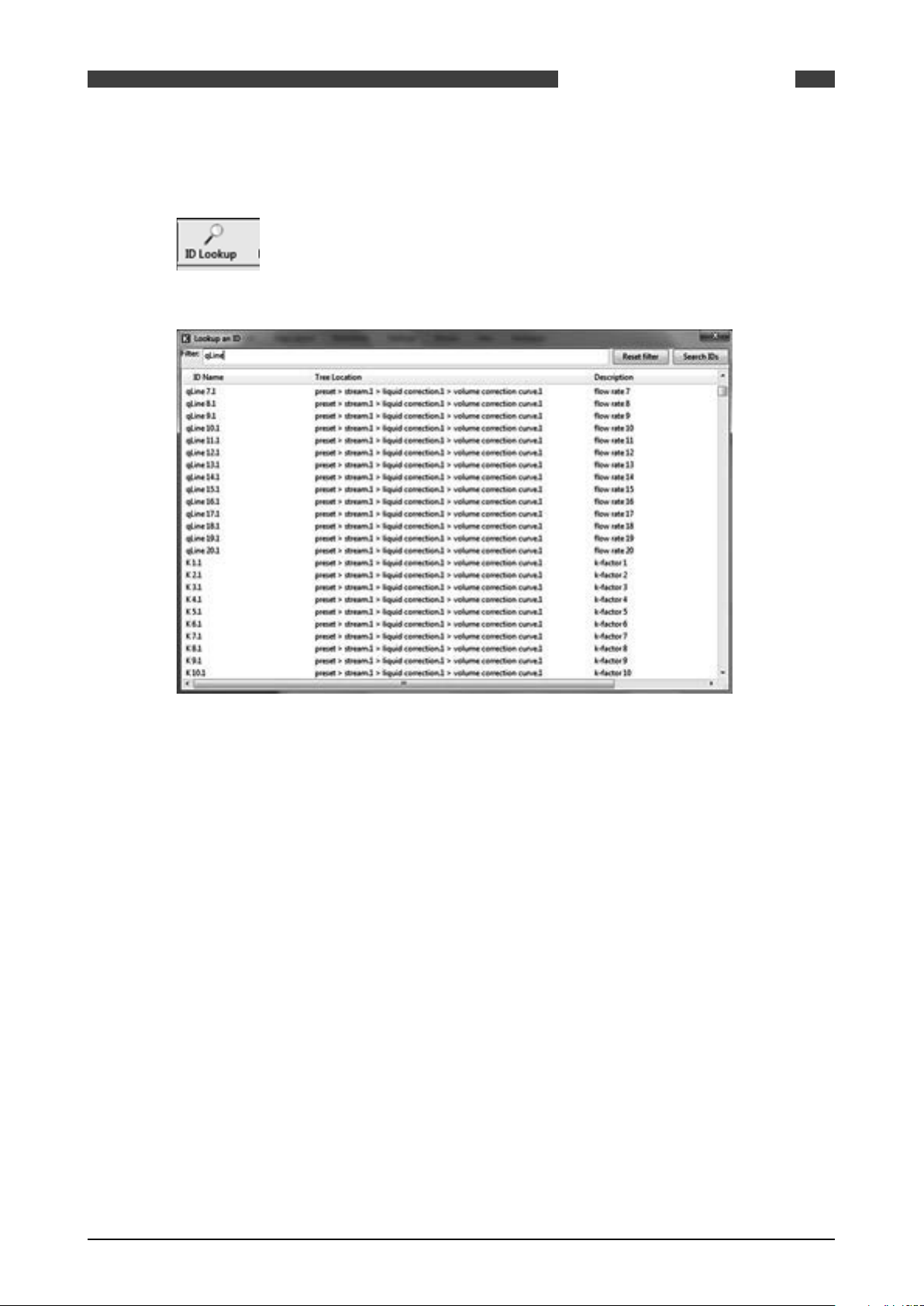
2.4.3 ID Lookup
When pressing the ID lookup button on top of the screen, a lookup table will be generated:
GENERAL INFORMATION
02
Figure 2 ID lookup
As there are very many ID’s, it is possible to filter for a required ID.
2.5 Specific Requirements for Meters and Volume Convertors
2.5.1 Numbering formats
The number formats used internally in the unit are generally IEEE Double Precision floating
point numbers of 64 bit resolution.
It is accepted that such numbers will yield a resolution of better than 14 significant digits.
In the case of Totalisation of Gas, Volumes, Mass and Energy such numbers are always shown to
a resolution of 8 digits before the decimal point and 4 after, i.e. 12 significant digits.
Depending upon the required significance of the lowest digit, these values can be scaled by a
further multiplier.
2.5.2 Alarms
Each of the various modules that comprise the total operating software, are continuously monitored for correct operation. Depending upon the configuration, the flow computer will complete its allotted tasks within the configured cycle time, 250mS, 500mS or 1 second. Failure to
complete the tasks within the time will force the module to complete, and where appropriate, a
substitute value issued together with an alarm indication.
For example, if a Calculation fails to complete correctly then a result of 1 or similar will be
returned, which allows the unit to continue functioning whilst an accountable alarm is raised,
indicating an internal problem.
08/2013 - MA SUMMIT 8800 Vol3 R02 en
www.krohne.com
19
Page 20

2.5.2.1 Accountable alarm
When the value of any measurement item or communication to an associated device that is providing measurement item to the SUMMIT 8800 goes out of range, the flow computer will issue
an Accountable Alarm.
When any calculation module or other item that in some way affects the ultimate calculation result goes outside its operating band, i.e. above Pressure Maximum or below Pressure minimum,
then the SUMMIT 8800 will issue an Accountable Alarm.
When the SUMMIT 8800 issues an Accountable alarm a number of consequences will occur as
follows:
Front panel accountable alarm will turn on and Flash.
Nature of accountable alarm will be shown on the top line of the alarm log.
Alarm log will wait for user acknowledgement of alarm.
During the period of the alarm, main totalisation will occur on the alarm counters.
2.5.3 Optional consequences
Depending upon the configuration of the SUMMIT 8800 the following optional Consequences will
also occur:
SUMMIT 8800GENERAL INFORMATION02
An Entry will be made in the Audit Log, with Time and Date of occurrence.
The “Used” value of the Parameter in Alarm will be substituted by an alternative value, either
from an alternative measurement source that is in range, or from a pre-set value.
A digital Alarm output will indicate an Alarm condition.
20 www.krohne.com 08/2013 - MA SUMMIT 8800 Vol3 R02 en
Page 21
SUMMIT 8800
3. CONFIGURATOR SOFTWARE
For initial installation of the software refer to Volume 1 of the handbook.
For Hardware and instrumentation, refer to Volume 2 of the handbook
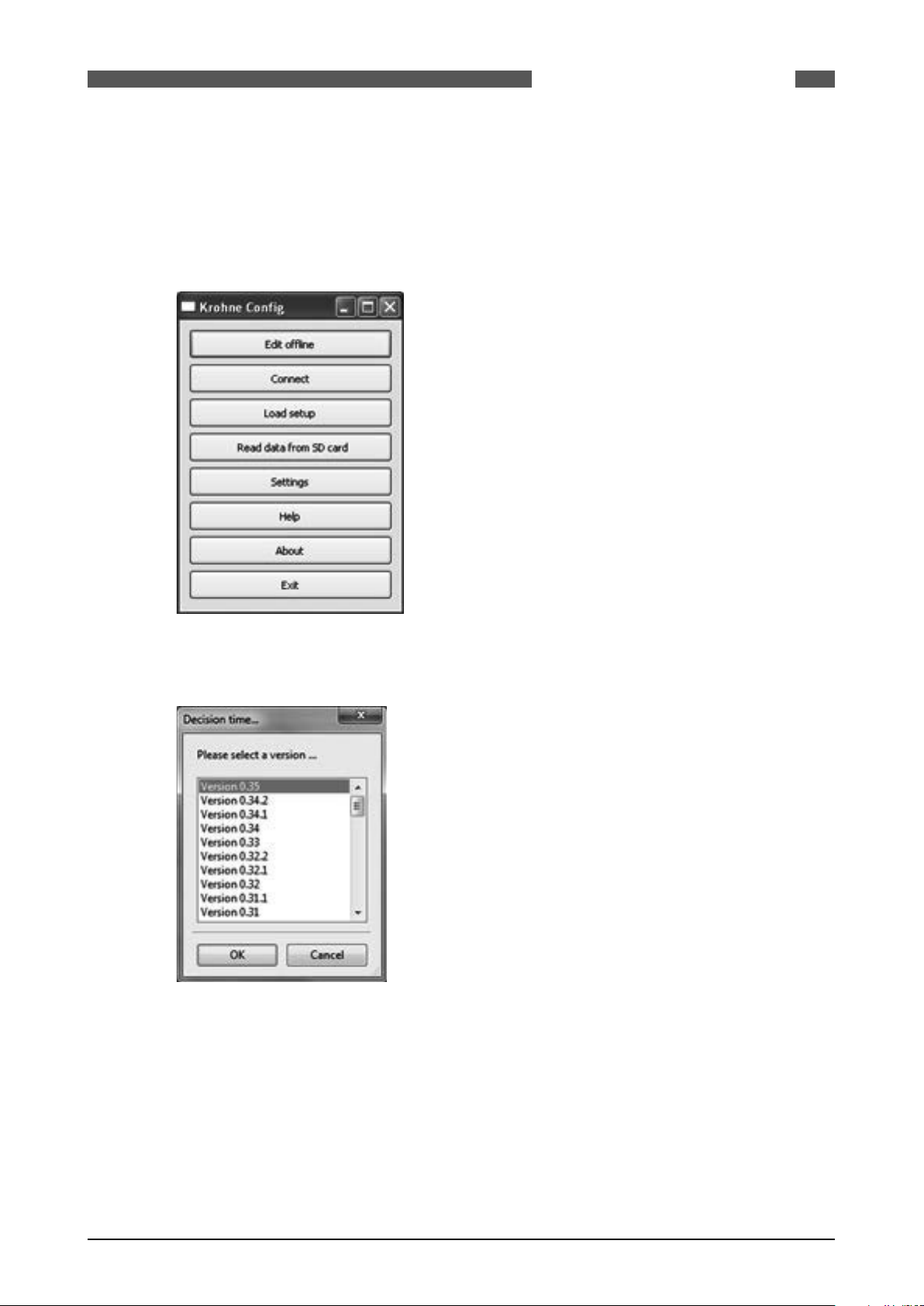
Alter starting the configuration software, the option menu appears:
CONFIGURATOR SOFTWARE
03
Figure 3 Configurator option selections
Select Edit Offline, this function allows the user to create or modify a new configuration without
actually being connected to the flow computer.
Figure 4 Application firmware version
Select the correct software version. The software must be compliant to the connected Summit
8800 firmware version, details of system information can be found in volume 1. We assume that
the version mentioned in append 1 is selected.
The main configuration page of the Configurator software is displayed and will be the starting
point for this manual.
08/2013 - MA SUMMIT 8800 Vol3 R02 en
www.krohne.com
21
Page 22

SUMMIT 8800CONFIGURATOR SOFTWARE03
Figure 5 Main Configurator display
22 www.krohne.com 08/2013 - MA SUMMIT 8800 Vol3 R02 en
Page 23

SUMMIT 8800 DATE & TIME
4. DATE & TIME
The Summit has a battery backed real-time clock. The clock can be set in several ways:
- Initially a fixed value via the configuration software
- Initially the time of the computer downloading the configuration software..
- Automatically synchronized via an SNTP server
- Manually via the screen
The format of the time can be changed to fit international needs.
The Summit also knows a contract time as often a buyer and seller have different moment of a
day that they like to generate reports, e.g. at 00:00 hours and 06:00 hours. Only required if more
than one report time is needed.
4.1 Initial setting of date and time
04
In the configuration software the initial settings for date and time can be set together with and
the display format and the contract time:
Figure 6 Date & time and contract time selection
Set date from Select from
• Don’t send Leave the Summit clock untouched.
• Set from PC’s date/time Change the Summit clock to the PC date/time when downloading the
• Set from custom settings Change the Summit clock to a manual settings when downloading
Date/ time Date and time for manual setting
Date / time format Select the format needed
Contract time Select the time as per customer needs.
08/2013 - MA SUMMIT 8800 Vol3 R02 en
software
www.krohne.com
23
Page 24

4.2 SNTP Time Synchronisation
The SNTP or Simple Network Time Protocol is available to synchronise the internal clock with a
network time server. While the internal clock’s accuracy is limited to about 3 ppm/°C, these time
servers are based on atomic clocks to guarantee the best accuracy. This function also ensures
that all flow computers in a network are using the same time.
The flow computer works with time servers using version 3 or 4 of the SNTP protocol, either
Unicast or Broadcast:
• Unicast is where the flow computer will request the time from a specified time server.
• Broadcast is when the flow computer waits for a broadcast packet from a time server, and
then confirms the results by using a unicast request.
The SNTP can be setup in the hardware section under the Ethernet SNTP:
SUMMIT 8800DATE & TIME04
Figure 7 SNTP Date & time general settings
Enable Click the box to enable SNTP
Operating mode Set the mode as unicast or multicast
Port The port used for SNTP standard specifies that this should be 123.
Min time adjustment Minimum amount of time the flow computer clock can be adjusted
Max time adjustment Maximum amount of time the flow computer clock can be adjusted
Max time without adjustment Maximum number of seconds that the flow computer can be expected
to operate without receiving a new time from the time server. If this time
is exceeded without receiving a new time then the flow computer will
give a warning.
Invalid time update limit Maximum number of bad updates that can be received before a warning
is given.
Ignore max adjust on startup Indicates if the maximum time adjustment value should be ignored for
the first valid time received by the flow computer after power up.
Offset from GMT The time zone of the local time as an offset from the atom clock +/-
GMT minutes
24 www.krohne.com 08/2013 - MA SUMMIT 8800 Vol3 R02 en
Page 25

SUMMIT 8800 DATE & TIME
Figure 8 SNTP Date & time unicast settings
Server timeout The timeout that applies to each server, after which the next available server in
the list is tried. It is recommended that this value is a factor of the maximum
time without adjustment.
Poll interval Frequency of the flow computer polling the time server. It is recommended that
this value is not divisible by 60.
Number of servers The number of time servers the flow computer can connect to.
Time server IP address of each server.
04
Figure 9 SNTP Date & time broadcast settings
Broadcast timeout The flow computer the waits for a broadcast before giving an alarm. It is
recommended that this value is a factor of the maximum time without
adjustment.
Broadcast domain. IP address on the client subnet for the client operating in broadcast mode to
listen for time updates from broadcast servers.
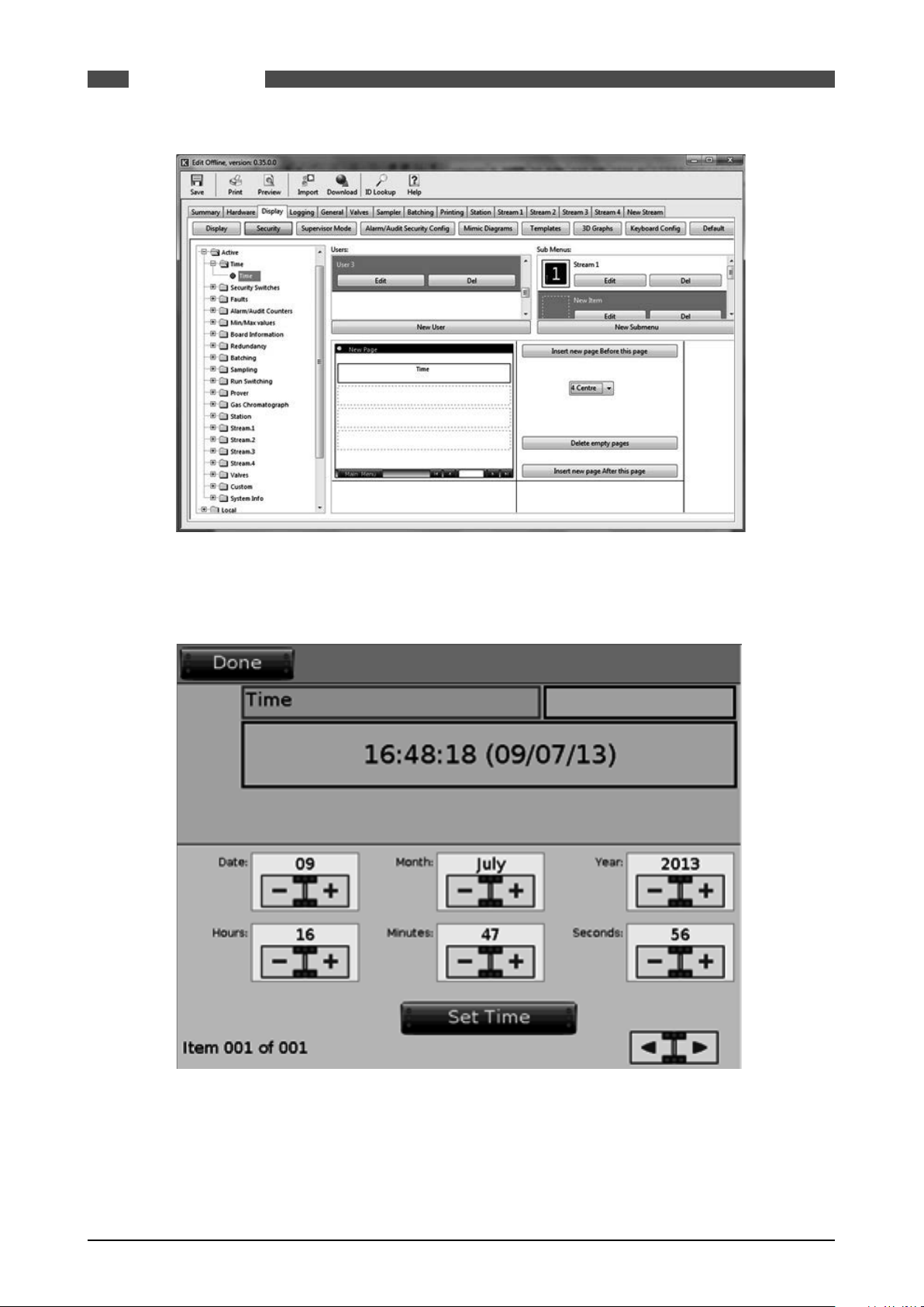
4.3 Manually change date and time
To be able to set the date and time manually, a display item has to be created under “Security”
with the time in it. (see also next chapter).
08/2013 - MA SUMMIT 8800 Vol3 R02 en
www.krohne.com
25
Page 26
SUMMIT 8800DATE & TIME04
Figure 10 Manual Date & time settings
If the operator then goes into Edit mode, he can change the time as follows:
Figure 11 Manual Date & time adjustment
26 www.krohne.com 08/2013 - MA SUMMIT 8800 Vol3 R02 en
Page 27
SUMMIT 8800 DATA LOGGING
5. DATA LOGGING
To store historical data is one of the major functions of a flow computer. The Summit 8800 is has
3 types of log’s:
Alarm log Storage of current and historical alarms.
Audit trail log Storage of any change made to the unit that has metrological significance.
Data log Storage of user defined data, either periodically or event diven.
The first two are system logs and cannot be changed, however an audit log can be extended with
user defined data.
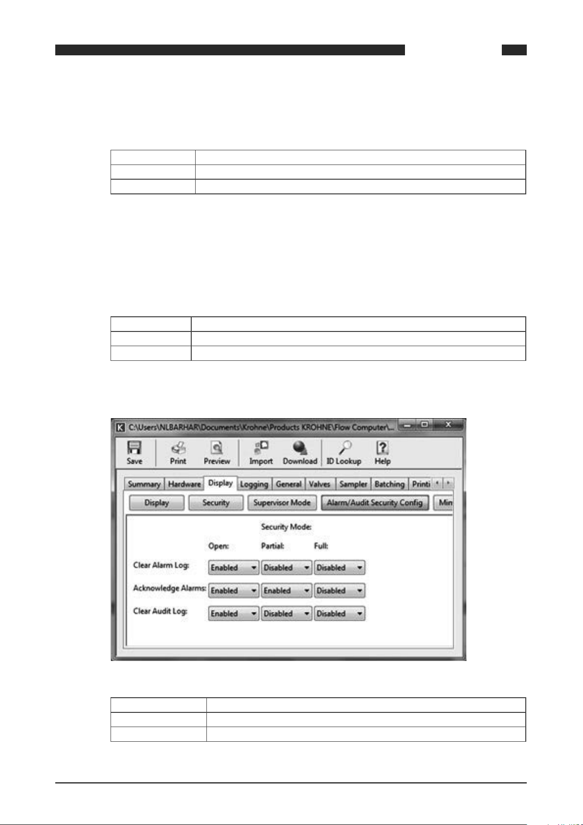
5.1 Alarm and audit log security
It is possible to define what to do with alarm acknowledgment and clearing alarm and audit logs
depending on the 4 hardware security switches on the back of the Summit. Two of them determine the security mode of the Summit:
Open Any changes can be made (using user passwords) and applications can be loaded.
Partial Changes can be made except calibration data. No new application can be loaded.
Full No changes in parameters, values or any other data is not possible.
05
The different security mode also effects the alarm/ audit clearing and acknowledgment and can
be set under “display, alarm/audit security configuration“
Figure 12 Display security window
Clear Alarm Log Determines if the alarm log may be cleared in open/ partial/ full mode.
Acknowledge Alarms Determines if the alarms may be acknowledged in open/ partial/ full mode.
Clear Audit Log Determines if the audit log may be cleared in open/ partial/ full mode.
08/2013 - MA SUMMIT 8800 Vol3 R02 en
www.krohne.com
27
Page 28

5.2 Alarm log
Every time an alarm or warning occurs, it will be stored in the alarm log. The log contains a
maximum of 200 entries consisting of time and date when the alarm occurred and vanished plus
a description of the alarm or warning.
SUMMIT 8800DATA LOGGING05
Figure 13 Alarm log
As the alarm log is a system functions, it does not need any configuration, exept for the alarm
acknowledge and clear, which is depending on the security configuration (see previous chapter)
All alarm information stored in the Summit’s internal data flash memory. Each record contains
a CRC 32 check which is generated when the log record is created and checked for validity each
time data is read from the Unit.
5.3 Audit trail log
Any change made in the Summit which influences the flow measurement in any way is stored in
an audit trail to be able to track back what went wrong and possibly recalculate the results.This
log contains a maximum of 200 kbyte of internal memory, typically good at least 2000 entries.
Each entry consists of time and date when the event occurred, the operator name, the description of the event and the value before and after change:
28 www.krohne.com 08/2013 - MA SUMMIT 8800 Vol3 R02 en
Page 29

SUMMIT 8800 DATA LOGGING
Figure 14 Audit trail log
05
Each record contains a CRC 32 check which is generated when the log record is created and
checked for validity each time data is read from the unit.
As the audit trail log is a system functions, it does not need any configuration. However, configuration of the audit acknowledge, which is depending on the security configuration, is possible
(see chapter Alarm and audit log security).
5.3.1 Audit log extension
For diagnostic purposes, the user can extend the audit trail with alarms and with up to 10 additional data items per event. These data will be stored on an external SD card only. Configuration
can be done under “general” :
08/2013 - MA SUMMIT 8800 Vol3 R02 en
www.krohne.com
29
Page 30

SUMMIT 8800DATA LOGGING05
Figure 15 Audit log extension
The user can select which alarm types are to be included in the audit log:
Figure 16 Audit log select alarms
Accountable alarms Alarms (min or max exceeded) which influence the flow measurements
Non-accountable alarms Alarms which do not influence the flow measurements
Warnings Warnings (hi or low exceeded) which do not influence the flow
measurements
Faults Hardware faults, such as wrong hardware cards inserted for this
application
Select which additional data is to be recorded for each audit event, often these are the flow
totals at time of event:
30 www.krohne.com 08/2013 - MA SUMMIT 8800 Vol3 R02 en
Page 31

SUMMIT 8800 DATA LOGGING
Figure 17 Audit log select variables
Drag the variables from the ID’s in the list to record the variable when an audit event occurs.
Determine what to do with the data:
05
Figure 18 Audit log options
%SD card to use The % memory on the external SD card before the log start from the
Read access level An access level for reading these data (for SOAP protocol only yet)
Write access level An access level for writing these data (for SOAP protocol only yet)
5.4 Data log
It is also possible to create logs to store user defined historical data periodically or at events.
Each data log will contain a time and date stamp of the time of the record plus user selected
data items:
beginning
08/2013 - MA SUMMIT 8800 Vol3 R02 en
www.krohne.com
31
Page 32

SUMMIT 8800DATA LOGGING05
Figure 19 Data logging
In total 10 data logs on internal memory and 5 data logs in external SD memory can be defined,
each with:
Figure 20 Data log select variables
Up to 50 variables, selectable form the ID tree. The logs settings are:
32 www.krohne.com 08/2013 - MA SUMMIT 8800 Vol3 R02 en
Page 33

SUMMIT 8800 DATA LOGGING
Figure 21 Data log settings
Read access level An access level for reading these data (for SOAP protocol only)
Write access level An access level for writing these data (for SOAP protocol only)
Setup name A name for this data log
Log every If the log is periodically, set here the log interval between 5 minutes and 1 year
Num. records The number of records after which the log start from the beginning again
Log change of If the log is event driven, select which variable, from the ID tree, triggers the
event
Be careful to select an variable which changes state, such as end of prove
Default display page Press when page must be displayed after the screen is not used for a period of
time
Add to display menu If checked, this mimic will be placed in the menu item “data logs”
If not checked, the mimic can be used as a display page.
05
The statistics of memory used is indicated on this page, in terms of time and amount of memory
used.
Figure 22 Data log statistics
The period of time the total record will cover
• How much memory is used for this log record
• How much memory is used for all log records
• How much memory is still free
• The maximum amount of memory available for logging.
Please note:
• All data log items are stored in either internal data flash memory or removable SD card
memory depending upon the configuration. Each record contains a CRC 32 which is generated
when the log record is created and checked for validity each time data is read from the Unit.
08/2013 - MA SUMMIT 8800 Vol3 R02 en
www.krohne.com
33
Page 34

• The Internal (DF) memory has a capacity of approximately 6 MB or approximately to 300,000
data records, with time and date for each.
• The SD memory used, depends on the size of the card and the % of SD card to use set for this
log record, e.g. 200.000.000 for a 4 GB card.
5.4.1 Access to data log
Log data are available for reporting and communication, but not for display. In many cases, data
logs are specifically used to allow re-print of data.
The logs have records with an index. The first index 1 is latest (youngest) record, the highest
index is the oldest.
Under the normal local variables there are two for log numbers:
SUMMIT 8800DATA LOGGING05
Figure 23 Data log local log numbers
Generate log Set to generate a log
Log counter Number of logs generated
For printing, ID’s can be added from the data, alarm and audit log after which the log record can
be chosen:
34 www.krohne.com 08/2013 - MA SUMMIT 8800 Vol3 R02 en
Page 35

SUMMIT 8800 DATA LOGGING
Figure 24 Data log ID’s for FTP printing with log record selection
For modbus, there is a special log data tab for ID’s from the data log and after entering the index
may be changed:
05
Figure 25 Data log ID’s for modbus with index selection
08/2013 - MA SUMMIT 8800 Vol3 R02 en
www.krohne.com
35
Page 36

6. DISPLAY AND WEB ACCESS
The Summit 8800 display capabilities can be accessed locally via its touch screen or remotely via
a web browser connected to the build-in Summit web browser. This means that it can be used
via a large local display, a phone, a tablet or a PC. It is also possible to download alarm and audit
logs and real-time ID reports. For details on operator display and web access, see volume 1.
The display screen capabilities of the SUMMIT 8800 represents a quantum leap for flow computers. Not only is it a colour display, but it is also fully graphics, presenting text, mimics, trends,
X-Y-Z charts etc. and it is also fully configurable.
When starting a new application, the configurator will automatically generate a default menu
depending on the type of streams/ prover chosen. Because the menu is created in the default
engineering units, it is very important to make sure that the correct engineering units are
chosen, otherwise the menu items have to be changed manually. So please check if they are set
correctly under “settings” of the configurator start menu:
SUMMIT 8800DISPLAY & WEB ACCESS06
Figure 26 Display, set the correct engineering units
Please note that the menu will not automatically be adjusted when adding a stream to prevent
damaging any changes made. If desired, it is possible to create a new application and import any
changes desired or just create new menu items using the appropriate templetes.
There are two type of display pages:
System pages These pages are deemed essential and will always be available
User defined pages All other pages are fully configurable
6.1 System pages
The Summit has standard pages which cannot be changed and will always be available. They
handle the system functions, such as:
36 www.krohne.com 08/2013 - MA SUMMIT 8800 Vol3 R02 en
Page 37

SUMMIT 8800 DISPLAY & WEB ACCESS
06
Figure 27 Alarm and audit log
08/2013 - MA SUMMIT 8800 Vol3 R02 en
www.krohne.com
37
Page 38

SUMMIT 8800DISPLAY & WEB ACCESS06
Figure 28 Edit mode and system information
Although the edit mode page to protect secure pages will always be there, the menu and pages
behind it are user definable.
38 www.krohne.com 08/2013 - MA SUMMIT 8800 Vol3 R02 en
Page 39

SUMMIT 8800 DISPLAY & WEB ACCESS
06
Figure 29 Settings, display settings and touchscreen calibration
08/2013 - MA SUMMIT 8800 Vol3 R02 en
www.krohne.com
39
Page 40

6.2 User defined pages
Except for system pages, there are pages which are fully user defined. With the configurator
software menu’s can be changed, added and deleted:
SUMMIT 8800DISPLAY & WEB ACCESS06
Figure 30 Display main page
There are 9 selections to change the screen navigation to access data within the flow computer:
Display To define the display pages for normal operation
Security To define the display pages for secure / edit mode operation
Supervisor Mode Sets supervisory mode for secure fields in normal operation
Alarm/Audit Security
Configuration
Mimic Diagrams To define graphic pages for normal mode
Templates Defines templates for formatting display pages
3D Graphs To define X-Y-Z charts for normal operation
Keyboard Configuration Defines the keyboard layout to adapt it to international keyboards
Default Set which page must be displayed when not used for a period of time
6.3 Display
The display main page, as depicted in Figure 30, allows to add, change or delete any display item
for normal operation.
The display has the following elements:
Determines actions allowed depending on the security dip switches
Main menu The vertical menu on the display when “main menu” is pressed
Submenu The horizontal menu when one of the main menu items with a right
arrow is pressed
Display page One of the information pages that can presented
Display item One of the items shown on a page
The display has multiple main menu items, each can have a submenus with multiple submenu
items. Each menu item can have one or more display pages associated to it. Each display page
can have multiple display items.
40 www.krohne.com 08/2013 - MA SUMMIT 8800 Vol3 R02 en
Page 41

SUMMIT 8800 DISPLAY & WEB ACCESS
6.3.1 Main menu & submenus
The top part of the display page defines the main menu and its submenus. They appear unmodified on the Summit display:
Figure 31 Configurator main menu & submenu
06
Figure 32 Display main menu & submenu
Both the main menu and submenu have several functions associated with it to modify the menu:
Make a new menu item Press the new (sub)menu button
Move a menu item On a menu, click and hold the left mouse button and drag it to another
Delete a menu item Press the delete key at the menu item or press the del button
Change a menu name Click the menu name or press edit , select the menu item and click the
Change a menu bitmap Click the menu bitmap or press edit, select the menu item and press edit.
Delete a menu bitmap Press edit, select the menu item and press delete.
08/2013 - MA SUMMIT 8800 Vol3 R02 en
location
name.
www.krohne.com
41
Page 42

6.3.1.1 Make a new (sub)menu item
Press “new (sub)menu” to add a new (sub)menu at the end of the list. For submenu’s an empty
item with one associated empty page will be added. For menu’s, there is the choice to create:
• an empty menu item: a menu item with associated submenu and display page will be added,
all empty.
• a menu from a template: a predefined menu with submenu and display pages will be added,
all populated
Press “new menu” to have the template selection:
SUMMIT 8800DISPLAY & WEB ACCESS06
Figure 33 New menu, select template
Here for instance a predefined run switching menu can be added.
A newly created menu items may be moved to a another place in the menu by pressing the left
mouse button and, while on the menu item, dragging it to the desired location.
42 www.krohne.com 08/2013 - MA SUMMIT 8800 Vol3 R02 en
Page 43

SUMMIT 8800 DISPLAY & WEB ACCESS
6.3.1.2 Change or delete a bitmap
In the main menu, simply click the name or the bitmap to change it or alternatively press edit:
06
Figure 34 Edit a menu item
From the menu list, select the bitmap to be modified. Press delete to remove the bitmap.
Press edit to change the bitmap and a bitmap editor appears:
Figure 35 Bit map editor
The bit editor is mostly self explanatory:
Brush Defines the shape of the “brush”, so the way bits are selected
Select colour Select the colour of the dot from the palette at the right
Zoom Increases or decreases the size of the picture
Actual icon Independent from zoom, the icon as appearing in the menu is at the right bottom
part.
Show grid / mask Shows the horizontal/ vertical lines or not. Shows the size of the picture
Import / export To get a picture from or to disk.
08/2013 - MA SUMMIT 8800 Vol3 R02 en
www.krohne.com
43
Page 44

Although an icon only is 48x48 dots, the picture imported may be larger. A section of the picture
may be selected to be stretched or cropped, after which it will be scaled down automatically. To
do so, a frame is used to select the part to be imported and pressing OK automatically imports
the selection:
Figure 36 Import bit map
6.3.2 Display page & items
The bottom part of the display page defines the display pages and their items belonging to the
menu and submenu selected. They appear very similar on the Summit display. The display items
are dragged from the ID list left:
SUMMIT 8800DISPLAY & WEB ACCESS06
Figure 37 Configure display page
44 www.krohne.com 08/2013 - MA SUMMIT 8800 Vol3 R02 en
Page 45

SUMMIT 8800 DISPLAY & WEB ACCESS
The display page has several functions associated with it to modify its contents:
Make a new page
Above the page: press insert new page before this page
Below the page: press insert new page after this page
At the end: right click below insert new page and choose “new page” or drag a
display item below the very end of the pages
Delete a display page Delete all items on the page and press delete empty pages
Change the page name Click on the name on top of the page to change it.
Set display as default Right click on the page. (for details, see chapter 7.11)
Set the page type Press the button “page type” and select the desired type, see chapter
7.3.3.
Select a display template Press the button “page type” and select template (for details, see chapter
0)
Create a display item From the ID list choose the item to be displayed and drag it to the page.
Delete a display items Select the correct display item or items and press the delete key,
Get details on display item Right click on a display item and choose the item name:
06
Figure 38 Display item details
6.3.3 Set the page type
There are several page types which define the layout of the display page:
Template Data can be dragged in a fixed layout, a template (see details in chapter 0).
Mimic A predefined mimic page will be shown (see details in chapter 0)
Log data (list) Predefined log data will be shown as a table (see details in chapter 6).
Log data (graph) Predefined log data will be shown as a graph (see details in chapter 6).
Graph A predefined X-Y-Z chart will be shown (see details in chapter 0).
Below please find examples of different page types.
08/2013 - MA SUMMIT 8800 Vol3 R02 en
www.krohne.com
45
Page 46

Figure 39 Display page based on 8 centre template
SUMMIT 8800DISPLAY & WEB ACCESS06
In the above example, the (sub)menu has 10 display pages associated with it. On the Summit,
the bottom right hand side is used to select one of the 10 pages. Page 2 is shown and it is populated with 8 display items on a 8 centre template.
Figure 40 Display page based on VU template
In the above example, page 2 is populated in a VU template with up to 10 display items left and
up to 3 VU meters right.
46 www.krohne.com 08/2013 - MA SUMMIT 8800 Vol3 R02 en
Page 47

SUMMIT 8800 DISPLAY & WEB ACCESS
Figure 41 Display page based on a mimic
06
Figure 42 Display page based on a mimic
In the above example the mimic page “ALTOSONIC” is presented.
Figure 43 Display page based on log data (list)
08/2013 - MA SUMMIT 8800 Vol3 R02 en
www.krohne.com
47
Page 48

SUMMIT 8800DISPLAY & WEB ACCESS06
In the above example, page 1 of 6 is displaying log date called “Stream 2” as a table.
Figure 44 Display page based on log data (Graph)
Here, page 1 of 6 is displaying log data called “Stream 2” and the K- and MF-factor displayed as
a graph.
Figure 45 Display page based on a X-Y-Z graph
In the above example, page 1 of 6 is displaying X-Y-Z graph called “test”.
48 www.krohne.com 08/2013 - MA SUMMIT 8800 Vol3 R02 en
Page 49

SUMMIT 8800 DISPLAY & WEB ACCESS
6.4 Security / edit mode
In security or edit mode authorised personnel can change parameters. With the configurator
(groups of) users can be created, each with their password and their specific menu of parameters that can be changed by such users.
06
Figure 46 Configurator security window
6.4.1 Users & submenus
The top part of the display page defines the users and their submenus. They appear similarly on
the Summit display:
Figure 47 Configurator users & submenus
08/2013 - MA SUMMIT 8800 Vol3 R02 en
www.krohne.com
49
Page 50

SUMMIT 8800DISPLAY & WEB ACCESS06
Figure 48 Summit users & submenu
As editing security submenu’s is identical to editing display submenu’s.
Users can be modified using several functions:
Make a new user Press the new user button, a new user will be added at the end
Move a user On a user, click and hold the left mouse button and drag him to
another location
Delete a user Press the delete key at the user or press the del button
Change a user name Click the user name or press edit and click the name.
Change a user password Press edit and click the password.
User calibration access Press edit and click the box
Figure 49 Edit users
By default 3 Users are defined:
User 1 Password 1111
User 2 Password 2222
User 3 Password 3333
6.4.2 Display page and items
As editing security display pages is identical to editing normal display pages. However in this
case only the display type “template” is available.
Please be aware only the red coloured ID’s in the list can actually be changed by a user via the
Summit screen.
50 www.krohne.com 08/2013 - MA SUMMIT 8800 Vol3 R02 en
Page 51

SUMMIT 8800 DISPLAY & WEB ACCESS
6.5 Supervisor Mode
Supervisor mode allows an authorized user to control a system like a normal supervisory or
SCADA system, by pressing buttons and by inline editing. For instance the following example
shows buttons control the sampler. On the left the supervisor did not log-in yet, so the buttons
are not activated, on the right he did, so the buttons can be used:
06
Figure 50 Same page in normal and in supervisor mode
To be able to use the buttons, supervisor mode must be activated as follows:
08/2013 - MA SUMMIT 8800 Vol3 R02 en
www.krohne.com
51
Page 52

SUMMIT 8800DISPLAY & WEB ACCESS06
Figure 51 Setup supervisor mode
Mode Enable or disable supervisory mode
Password An alphanumeric password of at least 5 characters
Commit data changes instantly Click if parameter changes may take place immediately or after
manual action
Enable auto logout Click if a password must expire after the Summit is not used for a
while
Logout after If enabled, enter the time to auto logout
Now in the Summit menu, an option “supervisor mode” appears with which a supervisor can
log-in and log-out:
52 www.krohne.com 08/2013 - MA SUMMIT 8800 Vol3 R02 en
Page 53

SUMMIT 8800 DISPLAY & WEB ACCESS
Figure 52 Summit supervisor mode login and logout
06
If logged-in, the supervisor mode is orange and on the top line, an orange supervisor mode icon
appears.
Please note that, as “commit data changes instantly” is not clicked, an option to manually commit data is available under the supervisory mode.
6.6 Alarm/Audit Security Configuration
It is possible to define what to do with alarm acknowledgment and clearing alarm and audit logs
depending on the hardware security switches. For details, see chapter 6.1.
6.7 Mimic Diagrams
The mimic screen of the flow computers sets the Summit 8800 apart from any other. Such pages
are fully graphical and can depict metering equipment, status, buttons, and any other picture.
This makes it a simple supervisory system, but please be aware that mimic diagrams are slower
than display pages,
When starting an new application the system automatically generates mimic diagrams, depending on the type of streams/ prover chosen. They are available as templates which can be used as
they are or can be changed to your liking. Because the templates are created in the default engineering units, it is very important to make sure that the correct engineering units are chosen,
otherwise the mimic items have to be changed manually.
Off course new mimic diagrams can also be made. The basic idea is that there is a coloured
canvas on which graphic items can be dragged. These items can then be configured for colour,
format, variable, alarms and warnings:
08/2013 - MA SUMMIT 8800 Vol3 R02 en
www.krohne.com
53
Page 54

SUMMIT 8800DISPLAY & WEB ACCESS06
Figure 53 Mimic display definition
6.7.1 Mimic diagram selection
The top part of the display defines the mimic page as a whole:
Figure 54 Create a mimic display canvas
With as functions:
Select an existing mimic Press “select mimic” to select a mimic from the list of existing mimics
Create a new mimic Press “new” to create a new mimic from a blank or template, see below
Rename an existing mimic Press “rename” to change the name of the mimic
Delete a mimic Press “delete” to remove the mimic. Note that there is no warning.
Add to display menu If checked, this mimic will be placed in the menu item “supervisory”
A new mimic can be created from:
If not checked, the mimic can be used as a display page. See chapter 7.3.3
A blank canvas An empty canvas will be generated
A template A predefined system template mimic will be used as a start of the mimic
Of course a name must be given to the new mimic.
54 www.krohne.com 08/2013 - MA SUMMIT 8800 Vol3 R02 en
Page 55

SUMMIT 8800 DISPLAY & WEB ACCESS
Figure 55 New mimic display
Once created, the following main functions can be used to create and display the mimic diagram:
Figure 56 Create a mimic display canvas
06
Use a template Press “template” to select one from a list and to put it on the current
Set the background colour Choose the canvas background colour from a palette of colours
Create a new mimic item Press “new item” to add one graphic item to the canvas, see next chapter.
6.7.2 New mimic item
By clicking the “new item” button, the canvas can be populated with graphic items fom a list:
Pipe With a selection from several different pipe segments
Line With a selection from several different lines
Meter With a selection from several different type of meters
Equipment With a selection from several different types of metering equipment
Arrows With a selection from several different arrows
Miscellaneous For status, valves, transmitters, solid box, variable, text and button
In this case as an ultrasonic meter is selected:
canvas
Also any picture and logo’s can be loaded from disk.
08/2013 - MA SUMMIT 8800 Vol3 R02 en
www.krohne.com
55
Page 56

Figure 57 New mimic item and right mouse click on an item
SUMMIT 8800DISPLAY & WEB ACCESS06
Several functions can be used to draw a complete page:
Move an item(group) Left mouse click on the middle dot in the item to drag the item
Scale an item Left mouse click on a side dot in the item to scale the item
Rotate, mirror or flip an item Right mouse click on an item and select the function desired
Change the order of items Right mouse click on an item and select move to front/ back or raise/
lower
Or press the button layer and select move to front/ back or raise/
lower
Duplicate an item(group) Right mouse click on an item and select duplicate
Delete an item(group) Right mouse click on an item and select delete or press the button
delete
Configure an item Press the button configure to change the behaviour of the item, see
next.
Group items Pressing the left mouse button, drag a square around items to be
grouped
Multiple mimic items can be dragged on the canvas to complete the page. The layer button can
be used to set the order of the different items: which has to be in front and which should be at
the back..
Please note that the item now appears in the right hand side item list.
6.7.3 Configure mimic item
To change the behaviour of the item, press the button “configure”. Depending on the type of
mimic item, one or more of the following properties may be configured:
56 www.krohne.com 08/2013 - MA SUMMIT 8800 Vol3 R02 en
Page 57

SUMMIT 8800 DISPLAY & WEB ACCESS
Colours Select the colours for the item for e.g. the foreground, background, alarm and warning
Alarms Select which ID’s must be used for this item to show an alarm
Warnings Select which ID’s must be used for this item to show an warning
Image The image can be changed, cropped and stretched
Operator Animate a picture depending on a comparison between an ID and a value
Operators can be: =, ≠, <, >, ≤, ≥.
Tex t Give the item a name
Variable Select the ID associated with this item
Format Define what should be shown with a variable: name, value, units, status and border
The most common form is the following:
06
The simplest form is for line/ thin pipes and solid boxes:
08/2013 - MA SUMMIT 8800 Vol3 R02 en
www.krohne.com
57
Page 58

SUMMIT 8800DISPLAY & WEB ACCESS06
For other items, such as transmitters, text, variables and buttons, slightly different configuration
is needed.
6.7.3.1 Colours
All mimic items have a colour associated to it. The configuration page can however be different
between items:
Figure 58 Mimic item configure colour
58 www.krohne.com 08/2013 - MA SUMMIT 8800 Vol3 R02 en
Page 59

SUMMIT 8800 DISPLAY & WEB ACCESS
Select the colours to be used for the mimic items. Normally these are:
Mask Colour the colour for the base or background of the item.
OK Colour the colour for the item when its status is OK
Alarm Colour the colour for the item when in alarm
Warning Colour the colour for the item when in warning
For buttons, to make them look more dynamic, the colouring of the background and text can
change depending if the button is:
Enabled The colour when the supervisory mode is enabled
Disabled The colour when the supervisory mode is disabled
Pressed The colour when the button is pressed
For text there is only a foreground and background colour.
For lines, thin pipes and solid boxes, there is only one colour, so the colour palette will be shown
immediately:
06
Figure 59 Mimic item colour palette
08/2013 - MA SUMMIT 8800 Vol3 R02 en
www.krohne.com
59
Page 60

6.7.3.2 Alarms and warnings
In most mimic items, colours can be depending on alarms or warnings. Here the actual alarm
and warning are defined.
SUMMIT 8800DISPLAY & WEB ACCESS06
Figure 60 Mimic item configure an alarm and warning
A selection can be made from an ID tree which alarms/ warnings are involved with the colour
change. This can be one single alarm, but can also be a combination of several alarms e.g. to
create one meter system alarm.
6.7.3.3 Image
Most mimic items have a picture that can be changed:
Figure 61 Mimic item configure image
The following options are available:
Edit the bitmap Change, import or export the bitmap at will.
Crop the bitmap Make the bitmap smaller
60 www.krohne.com 08/2013 - MA SUMMIT 8800 Vol3 R02 en
Page 61

SUMMIT 8800 DISPLAY & WEB ACCESS
Stretch the bitmap Make the bitmap wider or higher
Figure 62 Mimic item edit image and crop/stretch image
06
For details of editing, cropping and stretching. In this case however, the image is not limited to
48x48 bits
6.7.3.4 Operators
It is also possible to animate pictures. Often this is to change colour depending on the status of
the mimic item, but this can also be moving, rotation, sizing or even reshaping depending on any
ID in the tree.
For each shape animation one line will be defined with the condition under which the shape
should be chosen. This means that one ID must be chosen which animates the shape and multiple lines with
• Operator and value with associated picture
• Operator and ID with associated picture
The operators can be: =, ≠, <, >, ≤, ≥, and a condition can e.g. be “Fat simulation equals 0” to
turn off a light:
08/2013 - MA SUMMIT 8800 Vol3 R02 en
www.krohne.com
61
Page 62

Figure 63 Mimic item configure operators
SUMMIT 8800DISPLAY & WEB ACCESS06
Functions are:
ID Select the ID, which animates a mimic item, from a list
New Create a new line with an operator with value
Edit Change the line with an operator
Delete Delete the line with an operator
In case of new or edit, the above right hand side picture will appear. The top part defines the
condition in two forms: value and ID:
Figure 64 Mimic item configure condition
The lower part shows the image with as options:
Edit the bitmap Change, import or export the bitmap at will.
Crop the bitmap Make the bitmap smaller
Stretch the bitmap Make the bitmap wider or higher
62 www.krohne.com 08/2013 - MA SUMMIT 8800 Vol3 R02 en
Page 63

SUMMIT 8800 DISPLAY & WEB ACCESS
6.7.3.5 Text
For the mimic item “Text” the text must be entered as follows:
Figure 65 Mimic item configure text
06
6.7.3.6 Variable
A mimic item “variable” off course needs a variable to be defined, but also with a button a variable must be defined:
Figure 66 Mimic item configure variable
Select the ID of the variable from the ID list.
08/2013 - MA SUMMIT 8800 Vol3 R02 en
www.krohne.com
63
Page 64

6.7.3.7 Format
A few mimic items, such as “variable” and “button” also allow a format to be changed:
SUMMIT 8800DISPLAY & WEB ACCESS06
Figure 67 Mimic item configure format for a variable and for a button
The configuration page is different for the mimic item:
Variable Click the checkbox if the name, value, units, status and/or border must be shown
Button Define with clicking the checkbox what button(s) must be shown: off or on or both.
In case both the off and on buttons are clicked, then the alignment is important.
Select if the alignment must be horizontal, vertical or grid. For grid include the colums
and rows.
Figure 68 Mimic item configure format for a variable and for a button
In the above case:
Button 1 The no button is clicked
Button 2 The yes button is clicked
Button 3 Both the no and yes buttons are clicked with horizontal alignment
Button 4 Both the no and yes buttons are clicked with vertical alignment
Button 5 Both the no and yes buttons are clicked with grid alignment, 2 columns by 3 rows
6.8 Display templates
As described in the previous chapter, display pages are based on templates. A display template
only defines the layout in which variables will be presented and do not contain any values themselves. They will be added in the display itself.
Multiple items may be added to a maximum of 20.
A few templates, 10 centre, 8 centre and 4 centre are system templates and cannot be changed.
64 www.krohne.com 08/2013 - MA SUMMIT 8800 Vol3 R02 en
Page 65

SUMMIT 8800 DISPLAY & WEB ACCESS
The rest of the templates are user defined and configured similarly to a mimic diagram:
06
Figure 69 Display templates
6.8.1 Template selection
The top part of the display defines the template as a whole:
Figure 70 Create a template
With as functions:
Select an existing template Press “select template” to select a template from the existing templates
Create a new template Press “new” to create a new template from a blank, see below
Rename an existing template Press “rename” to change the name of the template
Delete a template Press “delete” to remove the template. Note that there is no warning.
For a new template press new. Off course a template should be given a descriptive name to easily identify it.
08/2013 - MA SUMMIT 8800 Vol3 R02 en
www.krohne.com
65
Page 66

SUMMIT 8800DISPLAY & WEB ACCESS06
Figure 71 New display template
Once created, the following main functions can be used to create and display the template:
Figure 72 Create a mimic display canvas
Set the background colour Choose the background colour from a pallet of colours
Create a new template item Press “new item” to add one item to the canvas, see next chapter.
6.8.2 New template item
By clicking the “new item” button, the page can be populated with items from a list:
Variable An alphanumeric item
VU meter A traditional meter with analog dial item
Bar graph A horizontal or vertical bar graph item
Trend A real-time trend graph item
Here an example of the 4 different template items:
Figure 73 A display template and right mouse click on item
66 www.krohne.com 08/2013 - MA SUMMIT 8800 Vol3 R02 en
Page 67

SUMMIT 8800 DISPLAY & WEB ACCESS
Several functions can be used to draw a complete page:
Move an item(group) Left mouse click and hold on the middle dot in the item to drag the item
Scale an item Left mouse click and hold on a side dot in the item to scale the item
Change the order of items Right mouse click on an item and select move to front/ back or raise/
lower
or press the button layer and select move to front/ back or raise/ lower
Duplicate an item(group) Right mouse click on an item and select duplicate
Delete an item(group) Right mouse click on an item and select delete or press the button delete
Configure an item Right mouse click on an item and select configure
or press the button configure to change the behaviour of the item, see
next.
Group items Pressing the left mouse button, drag a square around items to be
grouped
Multiple template items can be dragged on the page to complete the
page. The layer button can be used to set the order of the different items:
which has to be in front and which should be at the back.
To add a variable to the template, select new item then variable. A basic outline will appear on
the template.
06
Left click and hold on the centre dot of this item and it can then be moved.
Left click and hold on one of the corner dots to re-size the item.
Figure 74 Move and re-size an item
.
Please note that the item now appears in the right hand side item list.
When duplicating an item, the software incorrectly asks if you like to change ID indexes; Use “no
change”
08/2013 - MA SUMMIT 8800 Vol3 R02 en
www.krohne.com
67
Page 68

6.8.2.1 Variable
The variable item can be used as a place holder for any type of variable:
Figure 75 Template: variable configuration and Summit screen
Nothing needs to be configured for a variable.
SUMMIT 8800DISPLAY & WEB ACCESS06
6.8.2.2 VU Meter
A VU meter is a mimic of an analog panel meter. Multiple meters can be on one page, each with
their own settings:
Figure 76 Template: VU meter configuration and Summit screen
The big VU meter below left used the standard settings, the small meter below right uses the
settings below.
Right clicking on the VU Meter or pressing “configure”, will bring up the settings:
68 www.krohne.com 08/2013 - MA SUMMIT 8800 Vol3 R02 en
Page 69

SUMMIT 8800 DISPLAY & WEB ACCESS
06
Figure 77 Template: VU meter configure limits and colours
Configure Limits
Maximum The maximum value for the meter display
Minimum The minimum value for the meter display
High The high limit on the meter display
Low The low limit on the meter display
Configure Colours
Foreground Colour The Colour for the text of the item and scale
Background Colour The Colour for the background of the lower meter box with the ID name
Min Colour The Colour used for a value below the minimum limit
Max Colour The Colour used for a value above the maximum limit
Top Colour The Colour used for the background of the top part of the meter
Scale Colour The Colour for the meter scale.
ID Background Colour The Colour for the background of the lower meter box with the ID value
Needle Colour The Colour for the meter needle.
08/2013 - MA SUMMIT 8800 Vol3 R02 en
www.krohne.com
69
Page 70

6.8.2.3 Bar Graph
A vertical and horizontal bar graph can be used for one single ID, but can also be configured to
have multiple ID’s in case the limits and colours are the same:
Figure 78 Template: vertical bar graph configuration and Summit screen
SUMMIT 8800DISPLAY & WEB ACCESS06
Figure 79 Template: horizontal bar graph configuration and Summit screen
Figure 80 Template: two signed bar graphs for the configurator and Summit screen
Please note that there are odd and even bars. In this case the odd bars have a dark gray, the
even bars a light gray background.
The last example, the lower bar graph uses below settings.
Right clicking on the bar graph or pressing “configure”, will bring up the settings:
70 www.krohne.com 08/2013 - MA SUMMIT 8800 Vol3 R02 en
Page 71

SUMMIT 8800 DISPLAY & WEB ACCESS
06
Figure 81 Template: bar graphs configure limits and colours
Configure Limits
Num ID’s A maximum of 12 bars/variables to be displayed on the graph
Maximum The maximum value for the bar graph
Minimum The minimum value for the bar graph
High The high limit on the bar graph
Low The low limit on the bar graph
Configure Colours
Foreground Colour The colour for the text of the item
Background Colour The background colour of the horizontal or vertical axis
Min Colour The colour used for a value below the minimum limit
Max Colour The colour used for a value above the maximum limit
Bar Colour The colour for the Bar when normal (between min and max).
ID Background Colour The background colour of the ID value box
Item 1 Txt Colour The text colour on each odd bar
Item 2 Txt Colour The text colour on each even bar
Item 1 Bg Colour The background colour for each odd bar
Item 2 Bg Colour The background colour for each even bar
Grid 1 The colour for the minor grid lines
Grid 2 The colour for the major grid lines
08/2013 - MA SUMMIT 8800 Vol3 R02 en
www.krohne.com
71
Page 72

6.8.2.4 Trend
A trend is electronic pen writer which is blank and start writing at the moment a page is opened.
SUMMIT 8800DISPLAY & WEB ACCESS06
Figure 82 Template: trend configuration and Summit screen
Below the configuration of the lower trend:
Right clicking on the trend or pressing “configure”, will bring up the settings:
72 www.krohne.com 08/2013 - MA SUMMIT 8800 Vol3 R02 en
Page 73

SUMMIT 8800 DISPLAY & WEB ACCESS
06
Figure 83 Template: trend configure limits and colours
08/2013 - MA SUMMIT 8800 Vol3 R02 en
www.krohne.com
73
Page 74

SUMMIT 8800DISPLAY & WEB ACCESS06
Configure Limits
Num samples The number of samples on the trend graph (seconds if the cycle time=1)
Maximum The maximum value for the trend graph
Minimum The minimum value for the trend graph
High The high limit on the trend graph
Low The low limit on the trend graph
Configure Colours
Foreground colour The colour for the text of the item
Background colour The background colour of the variable box
Min colour The colour used for a value below the minimum limit
Max colour The colour used for a value above the maximum limit
Plot colour The pen colour for the trend.
Grid 1 colour The colour for the major grid lines
Grid 2 colour The colour for the minor grid lines
Graph Colour The colour for the background of the graph area
ID background colour The background colour of the ID value box
6.9 3D Graphs
A 3D graph is an excellent way to present a lot of data in an X-Y chart or an X-Y-Z chart. The actual chart can be build up from sets of X-Y-Z values, but can also be X-Y-Z data from variables.
These variables may be dynamic or static.
Figure 84 3D graph settings
74 www.krohne.com 08/2013 - MA SUMMIT 8800 Vol3 R02 en
Page 75

SUMMIT 8800 DISPLAY & WEB ACCESS
06
Figure 85 Summit 3D graph; X-Y-Z and X-Y chart example
08/2013 - MA SUMMIT 8800 Vol3 R02 en
www.krohne.com
75
Page 76

6.9.1 Graph selection
The top part of the display defines the graph as a whole:
Figure 86 Create a mimic display canvas
With as functions:
Select an existing graph Press “select graph” to select a graph from the list of existing graphs
Create a new graph Press “new” to create a new graph from a blank or template, see below
Rename an existing graph Press “rename” to change the name of the graph
Delete a graph Press “delete” to remove the graph. Note that there is no warning.
Add to display menu If checked, this graph will be placed in the menu item “supervisory”
A new mimic can be created and must be given a name:
SUMMIT 8800DISPLAY & WEB ACCESS06
If not checked, the graph can be used as a display page.
Figure 87 New graph display
Once created, the graph settings and options can be specified. In this case they refer to the
above X-Y chart:
6.9.2 Graph settings and options
Figure 88 New graph range settings
Range settings:
X-Y-Z The name of the axis
Min The minimum value of the axis.
Max The maximum value of the axis. If for Z min and max are the same, then it is a X-Y graph.
Control The current value of the ID will be a cursor going over the curve (sie 46% in above X-Y
curve)
Option The location of the axis: on both sides or only one, and which side
76 www.krohne.com 08/2013 - MA SUMMIT 8800 Vol3 R02 en
Page 77

SUMMIT 8800 DISPLAY & WEB ACCESS
Figure 89 New graph colour settings
Colour settings:
Background The background colour for the whole graph
Root axis The colour of the base of the axes (at minimum value)
Title The colour of the name of the axis
Axis 1 The colour for the major grid lines
Axis 2 The colour for the minor grid lines
Cursor The colour of the cursor
Cursor shadow The colour of the shadow of the cursor as it is projected on the axes
Label 1 and 2 Not (yet) in use.
06
Figure 90 New graph options
Options:
Show cursor Show the cursor with live values as defined under control
Show cursor highlights Show the position of the cursor as it is projected on the curves
Show cursor shadow Show the position of the cursor as it is projected on the axes
Show data points Show the given data points in the curve as an “x”
Enable dynamic profiles Normally the graph will be build when the page is accessed. Dynamic
means that the graph will be updated continuously. This will take more
processing power.
Z direction Defines the direction of the Z-axis (towards or away from the user) and
its angle
Default display Press when page must be displayed when the screen is not used for a
period of time
08/2013 - MA SUMMIT 8800 Vol3 R02 en
www.krohne.com
77
Page 78

6.9.3 3D graph profile
Up to 12 profiles can be defined for one graph, each defining a curve for the graph.
For example, profile 1 can be a curve of flow rate (X) against error (Y). Profiles 2 and 3 could be
the same curve at different pressures.
These curves can be presented in an X-Y graph or X-Y-Z graph depending on the min and max
values in Figure 88: if min and max are the same an X-Y graph will be shown, otherwise an X-YZ graph will be shown.
Each profile can be:
Created Press new
Changed Select the profile and press edit
Removed Select the profile and press delete
SUMMIT 8800DISPLAY & WEB ACCESS06
Figure 91 New graph profile
Then the next window will appear with on top::
Figure 92 Graph profile, Top
With as settings:
Colour The colour of the graph associated with this profile
Data format Select if the curve should be based on values to be entered or on variables in the ID list
78 www.krohne.com 08/2013 - MA SUMMIT 8800 Vol3 R02 en
Page 79

SUMMIT 8800 DISPLAY & WEB ACCESS
Figure 93 Graph profiles for value and ID’s
06
Depending on the data format selected the following is needed to fill the profile’s curve data:
6.9.3.1 3D graph profile values
Per profile multiple one Z-value and multiple lines of X-Y value pairs can be entered:
Figure 94 Graph profile, enter the X-Y pair for one line
Together all values in this profile form one curve.
An X-Y pair can also be changed (press edit) or removed (press delete)
6.9.3.2 3D graph profile ID’s
Per profile multiple one Z-variable can and multiple lines of X-Y variable pairs can be dragged-in
from the ID tree.
Together all values in this profile form one curve.
A X-Y pair can also be changed (press edit) or removed (press delete)
08/2013 - MA SUMMIT 8800 Vol3 R02 en
www.krohne.com
79
Page 80

6.10 Keyboard Configuration
The keyboard is needed to enter the supervisory password. The problem that many country have
different keyboard layouts can be solved by fully customizing a keyboard starting from a blank or
a QWERTY (UK English) type keyboard:
SUMMIT 8800DISPLAY & WEB ACCESS06
Figure 95 Display keyboard customisation and use
The top part of the display defines the keyboard as a whole:
Figure 96 Create a keyboard
With as functions:
Select an existing keyboard Press “select keyboard” to select a keyboard from the list
Create a new keyboard Press “new” to create a new keyboard from a blank or QUERTY, see
below
Rename an existing keyboard Press “rename” to change the name of the keyboard
Delete a keyboard Press “delete” to remove the keyboard. Note that there is no warning.
Default keyboard If checked, this keyboard will be the default keyboard
A new keyboard can be created from blank or QWERTY and must be given a name :
80 www.krohne.com 08/2013 - MA SUMMIT 8800 Vol3 R02 en
Page 81

SUMMIT 8800 DISPLAY & WEB ACCESS
Figure 97 New display keyboard
After highlighting a key, four possible characters can now be assigned to the key by entered
either directly from the keyboard or by entering a unicode number in the appropriate box:
Figure 98 Display keyboard, key definition
The four character are:
Main uppercase Character when shift is pressed or when caps lock is on
Main lowercase Character when shift is not pressed and caps lock is off
Function 1 (blue) Fn1 Character when blue fn is on
Function 2 (red) Fn2 Character when red fn is on.
06
The supported character set conforms to MES-2 and comprises most common, Latin, Greek and
Cyrillic extensions (1013 characters).
For instance a French keyboard could look like:
08/2013 - MA SUMMIT 8800 Vol3 R02 en
www.krohne.com
81
Page 82

SUMMIT 8800DISPLAY & WEB ACCESS06
Figure 99 Display French keyboard in configuration and on the Summit
6.11 Default
Any page that is shown on the main menu can be selected to be the default page; this is a specific screen which the screen will show after a certain time of inactivity on the Summit touch
screen. This can be a “screen saver”, but more often this will be an important overview screen.
Figure 100 Display default configuration
The settings are:
Figure 101 Display default settings
82 www.krohne.com 08/2013 - MA SUMMIT 8800 Vol3 R02 en
Page 83

SUMMIT 8800 DISPLAY & WEB ACCESS
Configure the display default:
Mode Select one of the pages in the list. See later
Timeout The time after inactivity when to jump to the default page
The pages in the mode list are normally the system pages. If the desired page is not shown in
the list then it can be added. On the mimic panel window and on option part of the 3D graphs
window there is a button “set as default” to do so. On the display pages, right mouse click on the
desired page and select “set as default” .
6.12 Translation to local language
English is the default language for the Summit, but it is possible to define a new language. This
can be done in the configurator:
06
Figure 102 Translation to Spanish
In the Summit, the language can then be selected under “settings/ display settings”:
08/2013 - MA SUMMIT 8800 Vol3 R02 en
www.krohne.com
83
Page 84

Figure 103 Selection of Spanish
The top part of the display defines the language as a whole:
SUMMIT 8800DISPLAY & WEB ACCESS06
Figure 104 Create a language
With as functions:
Select an existing language Press “select language” to select a language from the list
Create a new language Press “new” to create a new language
Delete a language Press “delete” to remove the language. Note that there is no warning.
Import a language Press “import” to read a language file from disk. See below
Export a language Press “export” to write a language file to disk. See below
The second line of the display is:
Figure 105 Name and search a language
With the following fields:
Language name The name for the new language
Filter list Enter a English text string to find it or reduce the length of the the
list below.
Used Check if this language should actually be used in the Summit
Than the actual list of all text to be translated appears:
84 www.krohne.com 08/2013 - MA SUMMIT 8800 Vol3 R02 en
Page 85

SUMMIT 8800 DISPLAY & WEB ACCESS
06
Figure 106 Language configuration
For each line to be translated, the target language will be typed in on the right. This is fine, if for
a project some operator screens must be translated. In that case it is enough to only translate a
selected few lines, all the others will still use English.
However the full translation includes almost 40.000 lines, although not all line need translation.
Therefore more often, actual translation will be done outside the configurator, e.g. in Excel by
exporting and importing the language file.
6.12.1 Importing a language file
It is possible to import a language from a disk. KROHNE has at this moment translation files
for:
• Spanish
• German
Others will become available in time. Please check for availability. Press import to get the file:
08/2013 - MA SUMMIT 8800 Vol3 R02 en
www.krohne.com
85
Page 86

Figure 107 Import a language file
SUMMIT 8800DISPLAY & WEB ACCESS06
6.12.2 Change a language in Excel
When pressing export, the name and location of the language file can be chosen. If there is already a language in the configurator, then the select which language you would like to export:
Figure 108 Select language to be exported
Select:
Yes To export the default English language text list
No To export the selected language text list
The file type is CSV with a comma as a separator. To import this into Excel choose “Open”,
choose “Text files” and select the correct directory and file to import:
The text import wizard will start. The only change to be made is on the second page: change
“Tab” into “Comma”
86 www.krohne.com 08/2013 - MA SUMMIT 8800 Vol3 R02 en
Page 87

SUMMIT 8800 DISPLAY & WEB ACCESS
Figure 109 Converting a language file in Excel
To change the language, translate the second column. Here search and replace may be helpful,
but be careful to use it correctly as it might change the wrong words.
KROHNE can also provide an Excel file which uses Google translate to change the different
lines, but this will never give the quality results needed, so it can only be used as a guide while
translating.
06
When translated, In Excel use save as, choose the file type “CSV (Comma Delimited)” and select
the correct directory and file to save:
Figure 110 Save as an Excel language CSV file
Then use the configurator Import function to get the new language.
08/2013 - MA SUMMIT 8800 Vol3 R02 en
www.krohne.com
87
Page 88

6.13 Web access
The Summit has a build-in web server which provides read-only access to all the displays and
allows download of ID reports of active data and of alarm and audit logs (for details, see volume
1). The web site can be accessed by entering its IP address in the browser when web access is
enabled:
,
SUMMIT 8800DISPLAY & WEB ACCESS06
Figure 111 Web access enabled
Assuming the standard setup for Ethernet, this would default be: //192.168.0.100 or any address defined. If a dual Ethernet is used, then even the displays can be viewed (read-only) via the
website:
Figure 112 Web access
88 www.krohne.com 08/2013 - MA SUMMIT 8800 Vol3 R02 en
Page 89

SUMMIT 8800 DISPLAY & WEB ACCESS
Setting up web access is very easy as all Summit displays can also be used in the web browser,
as they are automatically converted to HTML-5 pages. The only exception is the 3D graphic
pages that will not work (yet). All it needs is defining an Ethernet port and enabling the HTTP or
Hypertext Transfer Protocol:
06
Figure 113 Web access setup for Ethernet port 1
Select the enable tick box to activate the functionality and enter the following details:
Enable Click the box to enable web access via HTTP
Authentication Choose “basic” if login is required, otherwise choose “none”
User name The user name which needs to be entered during login
Password The password which needs to be entered during login
Realm The group the user belongs to
7. REPORTING
08/2013 - MA SUMMIT 8800 Vol3 R02 en
www.krohne.com
89
Page 90

The Summit has several ways to report metering information:
• Serial reports
Ticket printing via a serial port to a black and white, non-graphical printer
• Ethernet reports
FTP printing via Ethernet to a black and white or colour graphic printer
E-mailing via Ethernet to a mail server
XML electronic reporting via FTP to a computer disk
• Download reports
ID reports via an Ethernet download from a web site or read by the configuration program
Ticket printing can only handle fixed-width or non-proportional characters and printers with RS
232/ 485 serial links. This is ideal for simple panel mounted dot matrix printers.
More modern printers are typically Ethernet based and can handle coloured and proportional
fonts. For this FTP printing is more appropriate.
7.1 Serial ticket printing
A ticket printer can be connected to any of the serial ports, but some of the dot matrix printers
need a hardware handshake as is available on port 1 of the Ethernet boards:
SUMMIT 8800REPORTING07
Figure 114 Ticket printer
7.1.1 Serial port settings
Set the serial port to match the printer:
90 www.krohne.com 08/2013 - MA SUMMIT 8800 Vol3 R02 en
Page 91

SUMMIT 8800 REPORTING
Figure 115 Ticket printer settings
07
Baud rate The speed of transmission in bits per second between 300 and 38400.
Parity A check on correct transmission: none, odd, even, space or mark.
Stop bits Gap between two transmitted words, 1 or 2 stop bits
Mode RS232 or RS 485
Word size Size of 1 word: 7 or 8 bits
Page width The height in lines of the paper in the printer. Maximum 255.
Page height The width in characters of the paper in the printer. Maximum 255.
CTS Select if handshaking using the Clear To Send line on the RS232 link.
CTS timeout If handshaking is used, then define the maximum time should be waited before giving
7.1.2 Print jobs
The print Jobs page defines the configuration of the items to be printed and the circumstances:
an alarm when the printer is not getting ready.
Figure 116 Ticket printer print jobs
There is no limit to the number of print jobs that can be created, each theit own name:
08/2013 - MA SUMMIT 8800 Vol3 R02 en
www.krohne.com
91
Page 92

SUMMIT 8800REPORTING07
Figure 117 Ticket printer print jobs
With as functions:
Select an existing job Press “select language” to select a job from the list
Create a new job Press “new” to create a new job
Rename a job Press “rename” to change the job name
Delete a job Press “delete” to remove the job. Note that there is no warning.
The content of a report can be based on the standard variables or on data log values. To be able
to re-print the report, it is a good idea to base the report on a data log of print data.
Determine the report type:
Figure 118 Ticket printer print jobs
Report type In a standard report, only the row (or record) selected will be printed. In a row based
report, the user can choose which row to print.
Log data used in report Select an existing data log from the list
Determine when to print the report:
Figure 119 Ticket printer print conditions
There are 4 conditions to start the job:
92 www.krohne.com 08/2013 - MA SUMMIT 8800 Vol3 R02 en
Page 93

SUMMIT 8800 REPORTING
Manually via the print jobs screen at the SUMMIT 8800
Show on print menu Click if the job must be show in print menu of the main menu for manual
trigger
On interval, to print the job at a regular time intervals
Print every Select the interval between two reports from the list
Print interval offset Delaying a print by the offset time to prevent 2 Summits printing at the same
time.
On change of state of a variable
Print on change of Select the variable ID from the list. Care should be taken when selecting the ID
as a print will be generated on each change in state.
On an event, like a fault or alarm
Event variables Tick on the ID tree one or more boxes on which the event print should occur.
7.1.3 Configure report
To start making the actual content of the report press configure report:
07
Figure 120 Configure reports
On the right hand side there is the report which will normally be blank for a new report. Now it
is possible to drag items from the variable tree on the left hand side to create a report as shown.
Items can come from the real-time variables or from the data log and may include alarm and
audit data:
08/2013 - MA SUMMIT 8800 Vol3 R02 en
www.krohne.com
93
Page 94

SUMMIT 8800REPORTING07
Figure 121 Variable and log data ID selection
Text may be typed anywhere on the page after positioning the cursor to the desired location.
To scale a page, use the zoom function:
Figure 122 Zoom function
Zoom A page can be zoomed from 25% to 400%
7.1.4 Format the items
Options are available upon right clicking an item or a group of items. The content is different for
variable items and for data log items and the options are slightly different when selected or not.
Here the variable options:
Figure 123 Variable item options with formatting details
94 www.krohne.com 08/2013 - MA SUMMIT 8800 Vol3 R02 en
Page 95

SUMMIT 8800 REPORTING
Group an item or items Draw a green square around the item(s) and they will become blue.
Move an item (group) Group the item(s) and click and drag the item(s)
Right click on a variable:
Item details Clicking the first line shows the item details
Delete an item (group) Delete the selected item(s) by selecting the option or press the delete key
Copy an item (group) Copy the item to paste it elsewhere
Cut an item (group) Cut the item to paste it elsewhere
Change formatting Change the way the data is displayed
• Width The number of characters before the decimal point
• Decimal places The number of characters after the decimal point
• Max field width The total number of characters: adds spaces before the item if longer
Hide item name Do not use the item name and hide it. If desired, a text may be typed instead.
Hide item value Do not use the item value and hide it
Hide item units Do not use the item units and hide it. If desired, a text may be typed instead.
07
And here the data log options:
Figure 124 Data log item options with changed time period and format
08/2013 - MA SUMMIT 8800 Vol3 R02 en
www.krohne.com
95
Page 96

SUMMIT 8800REPORTING07
Group an item or items Draw a green square around the item(s) and they will become blue.
Move an item (group) Group the item(s) and click and drag the item(s)
Right click on a log item:
Item details Clicking the first line shows the item details
Delete an item (group) Delete the selected item(s) by selecting the option or press the delete key
Copy an item (group) Copy the item to paste it elsewhere
Cut an item (group) Cut the item to paste it elsewhere
Change formatting Change the way the data is displayed, as with variables, however for the log
time:
• Time format Change the time format to e.g. %D-%M-%y, %h:%m:%s for 16-07-2013,
12:24:32
• Invalid date format Give a string to indicate an no time is available (size must be equal to the
time format)
• Interval format If selected define how the interval (from/to time) should be presented e.g.
10:00 – 11:00
Create statistics Select to create statistics on a group of log records with options, see below.
Change number of rows Change the default number of rows (log size) to a given number of rows
Change period If not all rows are needed, it is possible to change the time period to:
Any missing records will be shown be indicated with a “-“ for the time
• All All records to be used
• Hour Only the records in the last hours will be printed
• Day Only the records in the last days will be printed
• Month Only the records in the last months will be printed
Order Select if the first record will be the oldest or the youngest record.
7.1.5 Add statistics
For a group of log data items choose “create statistics” on the right click menu:
Figure 125 Data log item Select statistics
A new statistical item appears, which is linked to the associated log data and which is the average of the log data items. By right clicking the statistical item the following statistical options
can be selected
96 www.krohne.com 08/2013 - MA SUMMIT 8800 Vol3 R02 en
Page 97

SUMMIT 8800 REPORTING
Sum Change the statistical item to be the sum of the data log items
Average Change the statistical item to be the average of the data log items
Min Change the statistical item to be the minimum of the data log items
Max Change the statistical item to be the maximum of the data log items
7.1.6 Multiple pages
A report can consist of multiple pages. To navigate through these pages use:
Figure 126 Page selection
Page Selection
<< Go to the first page
< Go to the previous page
Page n Go to page number n
> Go to the next page
>> Go to the last page
New Page Create a new page
Delete Page Delete the current page
Undo Undo an action
07
7.2 Ethernet reporting
Ethernet reporting uses the FTP and SMTP protocols:
FTP: FTP printing and file reporting
SMTP: E-mail reporting
To use them, these protocols must be set-up in the hardware section for single or dual Ethernet
boards:
08/2013 - MA SUMMIT 8800 Vol3 R02 en
www.krohne.com
97
Page 98

SUMMIT 8800REPORTING07
Figure 127 Ethernet port configuration
7.2.1 FTP protocol
FTP or File Transfer Protocol is a standard network protocol used to transfer files from one host
to another over a TCP based network. In the Summit FTP is used to transfer reports from the
flow computer to a printer or to a file server.
Figure 128 Ethernet port FTP configuration
Enable Click the box if FTP is used
Printer IP Provide the IP address of the receiving device
Username Set the username needed to access the receiving device.
Password Set the password needed to access the receiving device
For printers a username and password may not be needed, however they must be entered for
access to the user’s network servers.
Note: When using FTP to print data the printer or print server must (be set to) accept FTP connections. A majority of the more modern network enabled printers and print servers support
this protocol.
7.2.2 SMTP E-mail protocol
The SMTP or Simple Mail Transfer Protocol is an standard for electronic mail (e-mail) transmission across IP networks. Two independent SMTP protocols can be used:
98 www.krohne.com 08/2013 - MA SUMMIT 8800 Vol3 R02 en
Page 99

SUMMIT 8800 REPORTING
Figure 129 Ethernet port SMTP configuration
Enable Click the box if this SMTP protocol is used
FC e-mail address E-mail address of the flow computer
Username & password Password required to access the mail server
Domain Domain name of the server
SMTP server Address of the outgoing mail server
Recipient The mail can be send to up to 5 different recipients, each with:
Recipient type The report can be send: directly (To), as a circulation copy (Cc) or as a blind
copy (Bcc).
Recipient name The name of the recipient
Recipient email The e-mail address of the recipient
07
7.2.3 Print jobs
Reports can use the HTML XML formatting:
• HTML or HyperText Markup Language, allows for colour, formatting and charts.
• XML or eXtended Markup Language is a standard that allows a wide variety of programs, such
as Excel and Word to read and format the information. XML not only provides the actual data
but also associated information like the names and formats of the data.
File reports will most often be in XML, printers and E-mails will most commonly use HTML.
Please note that for some E-mail programs the HTML format must be enabled.
The print Jobs page defines the configuration of the items to be printed and the circumstances:
08/2013 - MA SUMMIT 8800 Vol3 R02 en
www.krohne.com
99
Page 100

SUMMIT 8800REPORTING07
Figure 130 Ethernet printjob configuration
There is no limit to the number of print jobs that can be created, each their own name:
Figure 131 Ethernet reporting print jobs
With as functions:
Add a new job Press “add” to create a new job
Select an existing job Select a job from the list
Delete a job Press “delete” to remove the job. Note that there is no warning.
(Re)name a job Type in the job name
Determine when to print the report:
100 www.krohne.com 08/2013 - MA SUMMIT 8800 Vol3 R02 en
 Loading...