

Page 1
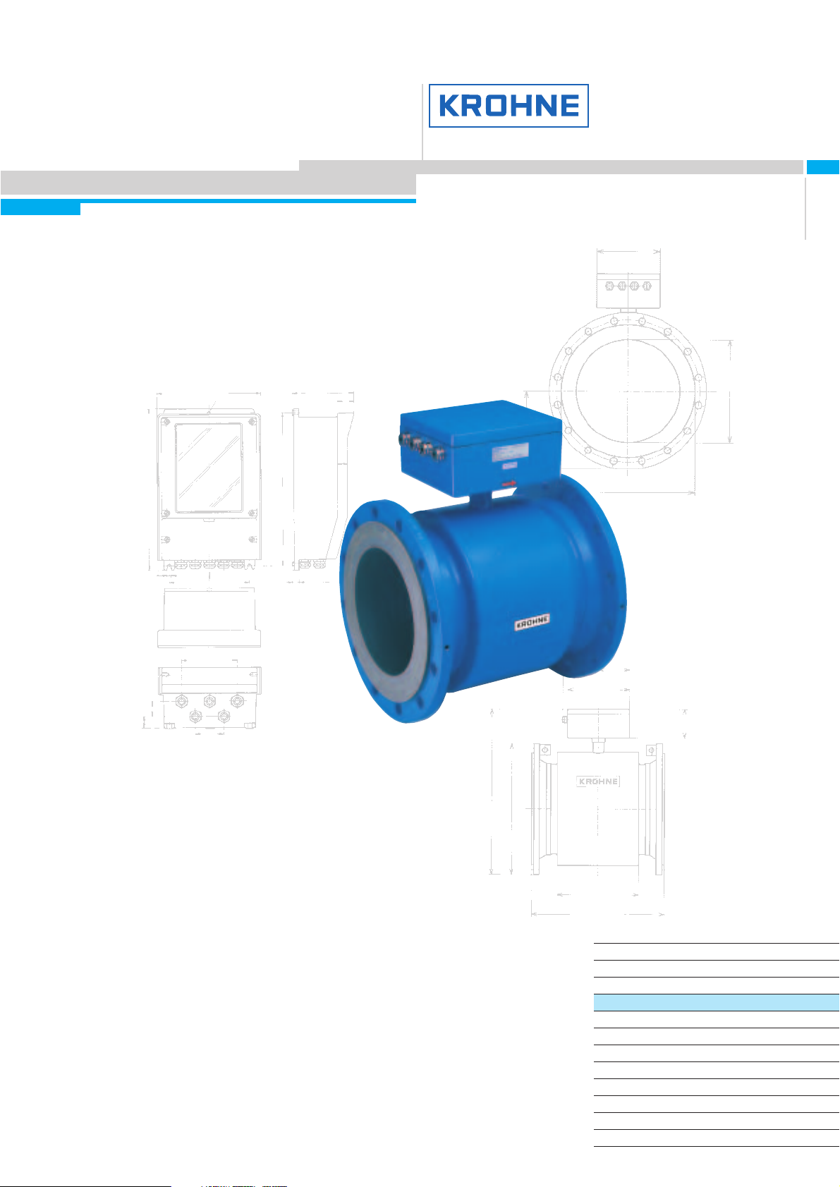
TIDALFLUX
IFM 4110 PF and IFM 4210 PF
Electromagnetic Flowmeter
for partially filled pipelines
● Measurement in partially filled pipelines
● Patented, non-contact level measurement
up to DN 1800 / 72"
● Electromagnetic process flow measurement
system, proven in more than 40 years in the
water and wastewater sector
GR
©
KROHNE 09/2003 7.02354.23.00
Variable area flowmeters
Vortex flowmeters
Flow controllers
Electromagnetic flowmeters
Ultrasonic flowmeters
Mass flowmeters
Level measuring instruments
Communications technology
Engineering systems & solutions
Switches, counters, displays and recorders
Heat metering
Pressure and temperature
Page 2

TIDALFLUX
flowmeters measure the volumetric flowrate
of electrically conductive liquids
in partially filled pipelines
Precision from KROHNE
● Developed for the water and waste water sector.
● In-depth testing in cooperation with leading companies in the waste
water sector.
● Steady display of measured values, even when product surface is
rough or the flow profile distorted.
● Precise factory calibration ensures a level of measurement accuracy
never possible before in partially filled pipes.
2
Innovative combination
of time-proven
measuring principles
The electromagnetic flowmeter and capacitive flow-level measuring system built into
the wall of the measuring tube provide
accurate flow measurements in partially
filled pipelines, with levels between 10 and
100 % of the pipe cross-section.
TIDALFLUX flowmeters measure the volumetric flowrate of electrically conductive liquids
in partially filled pipelines.
Fields of application
● Wastewater measurement in partially
filled pipelines
● Abrasion resistance: very high
● Chemical resistance:
alkaline solutions (e.g. NaOH)
up to 10% at 30°C / 86°F
acids (e.g. HNO
3
)
up to 5% at 20°C / 68°F
Calibrated on
EN 17 025
accredited
calibration rigs, accuracy of calibration
better than 99.97% of the measured value.
Determination of the flow
level and of the filled tube
cross-sectional area by
means of capacitive level
measurement and the
known inside tube diameter
without affecting the flow
profile
Determination of the flow
velocity by means of the
proven electromagnetic
measuring principle
Patented, capacitive
and non-contact flow
level measuring system,
integrated in the liner
Meter sizes
DN200-1800 / 8"-72"
Measuring error < 1% of the measured value
Exact measurements with a low time constant, even in cases of wave motion and
heavy contamination
Measurements
possible down to
10% filling of the
measuring tube
Page 3
TIDALFLUX 3
TIDALFLUX
Measuring principle
The TIDALFLUX IFM 4110 PF is an electromagnetic flowmeter with an
integrated capacitive level measurement system.
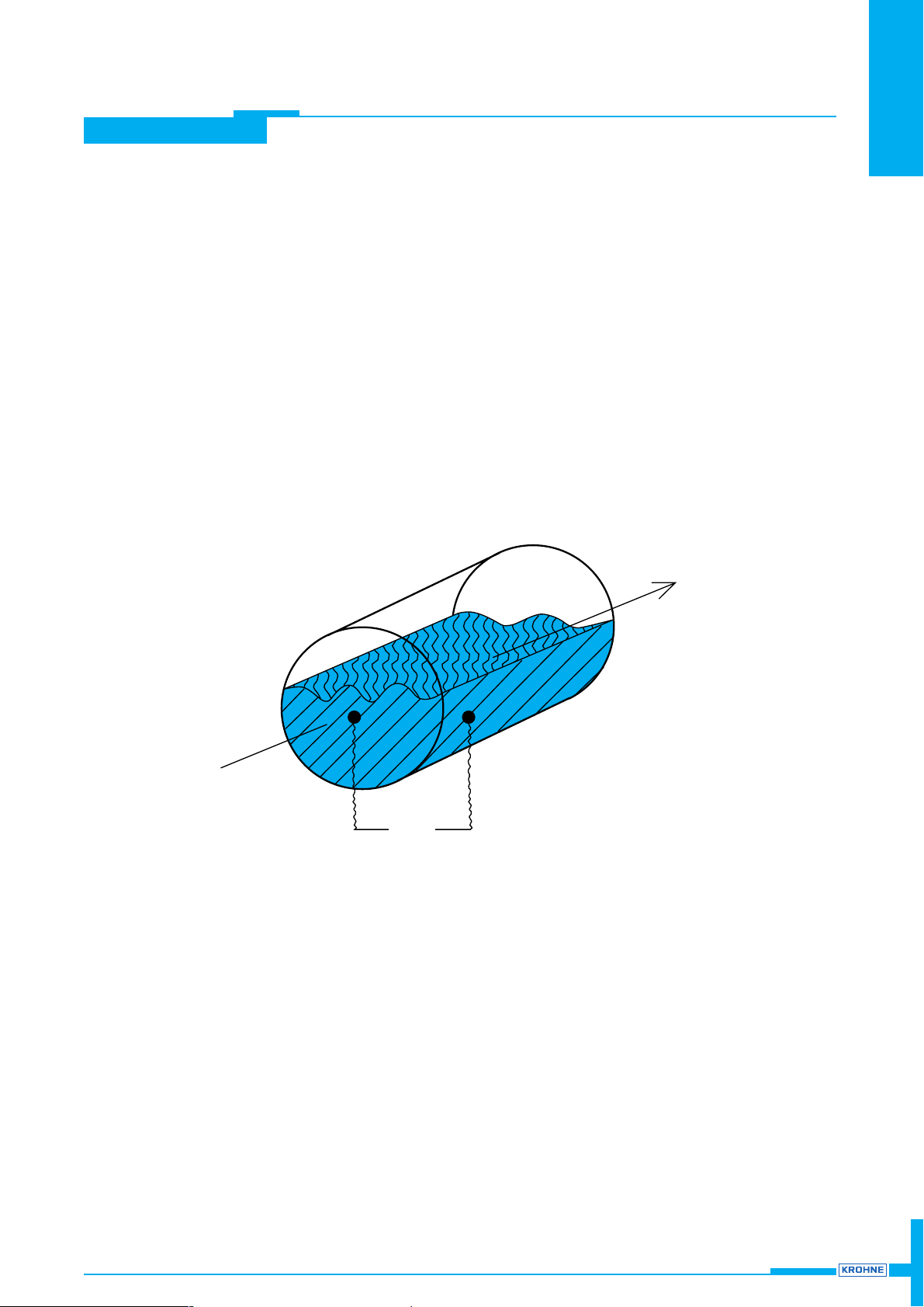
The flow rate Q(t) through the tube is: Q(t) = v × A
v = flow velocity of liquid product
A = wetted tube cross-section
Flow velocity v is determined on the basis of the known
electromagnetic measurement principle.
The two measuring electrodes are located in the lower part of the
measuring tube, on a level of approx. 10% of inside tube diameter.
Patented level measurement system
The wetted area A is computed from the known inside diameter of the
tube by the capacitive level measurement system that is built into the
measuring tube liner. The required electronics unit is accommodated in
a integral housing that is mounted direct on the primary head.
Communication with the remote signal converter is by way of an
RS 485 interface.
Capacitive flow level measurement
● Capacitive level measuring system
built into the measuring tube liner.
● Non-contact and accurate measurement of the flow level, with no
additional flow obstructions.
● Independent of flow profile influences, such as super-critical flow.
● Exact measurement of the flow level with low time constant, even
when waves are generated in the measuring tube.
● Reliable measurements, also when product is heavily
contaminated.
Electromagnetic flow measurement
● No constriction of the pipe cross-section.
● No additional pressure drop or backpressure.
● Linear and accurate flow measurements.
● Electromagnetic flowmeters from KROHNE are practice-proven for
over 40 years in the water and waste water sector
Q (t)
A
v
Page 4
TIDALFLUX
TIDALFLUX
4
Measuring range and accuracies
Full-scale range Q
100%
in pipe running full between 34 m3/h or 160 US Gal/min (minimum for DN 200 / 8”)
and 100000m
3
/h or 500000US Gal/min (maximum for DN 1800 / 72”)
equivalent flow velocity 0,3 – 12 m/s or 1 – 40 ft/s
Units m3, litres or US gallons per second, minute or hour,
and 1 user-defined unit, e.g. litres per day or US million gallons per day
Error limits to reference conditions
Partially filled pipe for full-scale ranges v ≥ 1 m/s (≥ 3.3 ft/s): ≤ 1 % of full-scale range
Completely filled pipe for current measured values v ≥ 1 m/s (≥ 3.3 ft/s): ≤ 1 % of measured value
v < 1 m/s (≥ 3.3 ft/s): ≤ 0.5 % of measured value + 5 mm/s or
≤ 0.5 % of measured value + 0.20 inches/s
Reference conditions:
Product water at 10 – 30°C / 50 – 86°F
Electrical conductivity > 300 µS/cm
Power supply (line voltage) UN (± 2%)
Ambient temperature 20 – 22°C / 68 – 71.6°F
Warm-up time 60 min
Max. error of calibration system 10 x smaller than F
Inlet / outlet runs 10 x DN / 5 x DN (DN = meter size)
Primary head properly grounded and centered
Page 5

TIDALFLUX 5
TIDALFLUX
Technical data
Meter sizes and versions
Meter sizes DN200 - 1600 / 8” - 64”,
Connecting flanges
DIN 2501 DN200 – 1800 / PN2.5 – PN 10
ANSI B16.5 8” – 72” / 150lb
AWWA and others on request
Protection category (IEC 529 / EN 60529) IP 67, equivalent to NEMA 6
Hazardous-duty version optionally Ex N, Zone 2
Process data
Liquid product water, waste water and chemical
Electrical conductivity ≥ 50µS/cm
Flow level in pipe min. 10 % of inside tube diameter
Process temperature –5 to + 60°C / + 23 to + 140°F
Ambient temperature – 25 to + 60°C / – 13 to + 140°F
Operating pressure max. 10bar / 150 psig
Integrated flow measuring system
Measuring principle electromagnetic flow measurement
Full-scale range Q
100%
in pipe running full between 34m3/h or 160US Gal/min (minimum for DN200 / 8”)
and 100 000 m
3
/h or 500 000 US Gal/min (maximum for DN1600 / 64”)
equivalent flow velocity 0.3 – 12m/s or 1 – 40 ft/s
Electrode design 1 pair of electrodes, solidly fitted, surface polished
Power for field coils from signal converter
Grounding rings available as an option
Integrated level measuring system
Measuring principle capacitive level measurement, built into the measuring tube liner
Pipe fill min. 10% of inside tube diameter,
outputs go to “zero” below 10% fill
Power for level measuring system
Voltage / frequency 230 / 115V AC, 50 – 60 Hz, others on request
Power consumption 14 VA
Communication with signal converter via RS 485 interface
Electronics housing integral, mounted directly on the primary head
Cable entries 3 x PG 16 and 1 x PG 9, optionally 1/2” NPT or 1/2”PF
Materials of construction
Measuring tube stainless steel 1.4301 (or higher materials number) / AISI 304
Liner Irathane®, 12 mm / 0.47”
Electrodes Hastelloy C4, others on request
Connecting flanges* steel 1.0038 (RST 37.2)
Converter housing* sheet steel
Electronics housing* cast aluminium
PG cable entries nickel-plated brass
Grounding rings (option) stainless steel 1.4571 / AISI 316 Ti
* with polyurethane finish 143 RAL 5015
The responsibility as to the suitability, intended use and corrosion-resistance of the materials used in
their construction rests solely with the purchaser.
Page 6
TIDALFLUX
6
TIDALFLUX
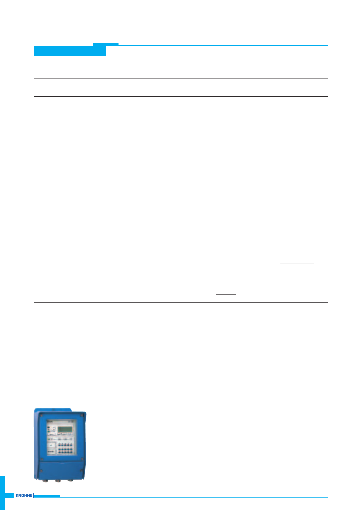
IFC 110 PF Signal converter
Version
IFC 110 PF Display version, with local display / control elements (15 keys)
Current output
Function – all operating data configurable
–galvanically isolated from all input and output circuits
Current: fixed ranges 0 – 20 mA und 4 – 20 mA
variable ranges for Q = 0% I
0
%
= 0 – 16mA
for Q = 100% I
100%
= 4 – 20mA
for Q > 100% I > 20 – 22mA (maximum)
Load min. 15 Ω
Error identification 0 / 22 mA and variable
Pulse outputs (passive) PA1(can also be operated as status output)
Function – for electronic totalizers – for electromechanical totalizers
– all operating data configurable – all operating data configurable
Ter minals P / P A1 / A⊥
Pulse rate 0 – 10 000 pulses per 0 – 50 pulses per
s [= Hz], min, h, m
3
, liter, etc., s [= Hz], min, h, m3, liter, etc.,
any scaling any scaling
Electrical data galvanically isolated galvanically isolated, but not from A2
U ≤ 32 V DC / ≤ 24 V AC U ≤ 32V DC / ≤ 24V AC
I ≤ 30mA, any polarity I ≤ 100mA, any polarity
or U ≤ 32 V DC, I ≤ 200mA,
note polarity
Pulse width automatic: pulse duty cycle 1:1, max. 10 000 pulses/s = 10kHz
variable: 10ms – 1 s, P
100%
[pulses/s] = fmax [Hz] =
digital pulse division, interpulse period non-uniform, therefore if frequency
and cycle meters connected allow for minimum counting interval:
gate time, totalizer ≥
Status outputs (passive) D1 / D2 / A2 A1 (can also be operated as pulse output)
Function, set for trip point trip point
automatic range change automatic range change
error identification error identification
overdriving overdriving
empty pipeline, < 10% empty pipeline, < 10%
Ter minals D1 / D⊥ A1 / A⊥
D2 / D⊥
A2 / A⊥
Please note: D⊥ common reference potential for D1 and D2
A⊥ common reference potential for A1 and A2
Electrical data galvanically isolated galvanically isolated, but not from A2
U ≤ 32 V DC / ≤ 24V AC U ≤ 32V DC / ≤ 24V AC
I ≤ 100 mA, any polarity I ≤ 100mA, any polarity
or U ≤ 32V DC, I ≤ 200mA,
please note polarity
}
adjustable in 1mA increments
1
2 x pulse width
1000
P
100%
[Hz]
Page 7
7
TIDALFLUX
TIDALFLUX
Control inputs C1 and C2 (passive)
Function, set for automatic range change, totalizer reset, error reset, start self-test,
set outputs to min. values or hold last measured values of outputs
Ter minals C1 / C⊥ and C2 / C⊥
(Please note: C⊥ common reference potential for C1 and C2)
Electrical data galvanically isolated, U = 8 – 32V DC, I ≤ 10mA, any polarity
Internal power supply for passive outputs and inputs and external receiver instruments
Ter minals E + and E –, please note polarity
Electrical data galvanically isolated / U = 24V DC / Ri = approx. 15Ω / I ≤ 100mA
Time constant 0.2 – 99.9s, adjustable in increments of 0.1second
Local display 3-line back-lit LCD
Display function actual flowrate, sum totalizers (7 digits)
or 25-character bar graph with percent display, status messages, level
Units: actual flowrate m
3
/h, liter/s., US gallons/min or user-defined unit,
e. g. hecto liter/h or US million gallons/day
totalizer m
3
, liter, or US gallons or user-defined unit, e. g. hecto liter or US million gallons
(adjustable counting time till overflow)
level percent of tube diameter
Language of plain texts English, German, French, others on request
Display: 1st line 8-character, 7-segment, numerical and sign display,
and symbols for key acknowledgement
2nd line 10-character, 14-segment, text display
3rd line 6 markers to identify display in measuring mode
Field power supply
Type pulsed bipolar DC field for all KROHNE primary heads,
galvanically isolated from all input and output circuits
Ter minals 7 and 8, each 2 ×
Current / voltage ± 0.125A (± 5%) / maximum 40V
Clock frequency
1
/36to 1/6of power frequency,
configurable to the calibration data of the primary head
Power supply AC version
Voltage range (without change over) 115/230 V AC
Frequency 48 – 63Hz
Power consumption (incl. primary head) 12W, typical (max. 18W)
Field housing
Material die-cast aluminium with polyurethane finish
Ambient temperature operation:
– 25 to + 60°C / – 13 to + 140°F storage: – 40 to + 60°C/ – 40 to + 140°F
Protection category (IEC529 / EN60529) IP 65, equivalent to NEMA 4 / 4X
Page 8
TIDAFLUX
8
TIDAFLUX
IFC 210 PF Signal converter
Versions
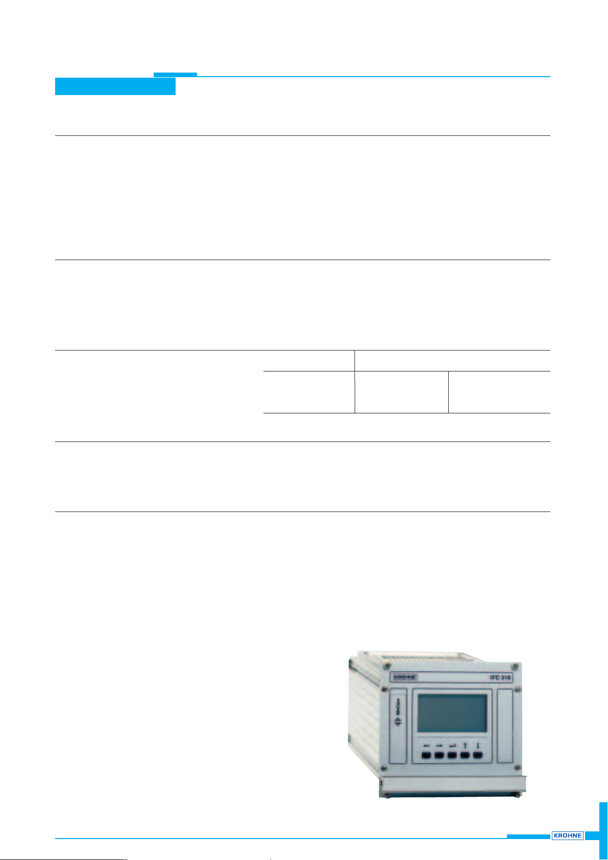
IFC 210 E (standard) – standard version with large graphics LC display and integrated
HART® interface
IFC 210 E / RS 485 (option) – same as standard version, additional with RS 485 interface
IFC 210 E / _ / Ex (option) – same as standard version, for operation with primary heads
used in hazardous areas
Interface module (option) – RS 485 / Profibus PA (in preparation)
Full-scale range
Flowrate for Q = 100% 6 Liter/h to 86850 m
3
/h or 0.03 to 400 000 US Gal/min,
corresponding to flow velocity v = 0.3 – 12m/s or v = 1 to 40ft/s
Units m
3
/h, liter/s, US Gal/min or user-defined unit, e. g. liter/day or US Gal/day
Current output
Function – all operating data configurable
–galvanically isolated from all input and output circuits
– active and passive operation
Current: fixed ranges 0 – 20 mA and 4 – 20 mA
variable ranges for Q = 0% I
0%
= 0 – 16mA
for Q = 100% I
100%
= 4 – 20mA
}
adjustable in 1mA increments
for Q > 100% I
max.
= 22mA
Load (active operation) max. 800 Ω
Error identification 0 / 22 mA and variable
Forward/reverse flow measurement direction identified via status output
Pulse output
Interface module (option) – RS 485 / Profibus PA (in preparation)
Function – all operating data configurable
–galvanically isolated from all input and output circuits
– digital pulse division, interpulse period non-uniform, therefore if
frequency and cycle meters connected allow for minimum counting interval:
gate time, totalizer ≥
1000
P
100%
[Hz]
Active mode connection: electronic totalizers
Passive mode connection: electronic or electromechanical totalizers
Electrical data see “Connection diagrams” on Pages 8 and 9
Pulse width automatic: pulse duty cycle 1:1, max 10000 pulses/s = 10 kHz
variable: 10 ms – 1 s P
100%
[pulses/s] = f
max
[Hz] =
1
2 x pulse width
Forward/reverse flow measurement flow direction identified via status output
Status output (passive)
Function configurable as measuring range identification for BA mode, indicator for
flow direction, errors or trip point
Electrical data see “Connection diagrams” on Page 9
Control input (passive)
Function – configurable for range change, totalizer reset, error reset,
set outputs to min. values or hold actual output values
– initiate function by ”low” or ”high” control signals
Control signals Umax: 24 V AC 32 V DC (any polarity)
low: ≤ 1,4 V ≤ 2 V
high: ≥ 3 V ≥ 4 V
Time constant 0.2 – 99.9 s, adjustable in increments of 0.1 second
Low-flow cutoff
Cutoff ”on” value: 1 – 19%
Cutoff ”off” value: 2 – 20%
}
of Q
100%
, adjustable in 1% increments
Page 9
9
TIDAFLUX
TIDAFLUX
Local display
high-contrast, illuminated graphics LC display, temperature-compensated,
excellent readability, 128 x 64 dots,
view surface approx. 69 mm x 36 mm (2.70” x 1.40”)
Display function actual flowrate, forward, reverse, sum totalizers, or bar graph and status messages
Units: actual flowrate m
3
/h, liter/s., US gallons/min or user-defined unit,
e. g. hecto liter/h or US million gallons/day
totalizer m
3
, liter, or US gallons or user-defined unit, e. g. hecto liter or US million gallons
(adjustable counting time till overflow)
Language of plain texts English, German, French, others on request
Field power supply
Type pulsed bipolar DC field for all KROHNE primary heads,
galvanically isolated from all input and output circuits
Ter minals 2 x 7 and 8
Current / voltage ± 0.125 A (± 5%) / maximum 40 V
Clock frequency
1
/36to 1/2of power frequency,
configurable to the calibration data of the primary head
Power supply AC version AC / DC version (switch-selectable)
standard option
Voltage range (without change over) 100 – 230 V AC 24 V AC 24 V DC
Tolerance band 85 – 255 VAC 20.4 – 26.4 V AC 18 – 31.2 V DC
Frequency 48 – 63 Hz 48 – 63 Hz –
Power consumption (incl. primary head) 11 W, typical (max. 14 W) 11 W, typical (max. 14 W) 11 W, typical (max. 14 W)
When connected to a functional extra-low voltage, 24 V AC / DC, protective separation (PELV)
must be ensured (VDE 0100 / VDE 0106 and IEC 364 / IEC 536 or equivalent national standards).
Housing
Material aluminium section, stainless steel and aluminium sheet, partially polyester coated
Ambient temperature operation: – 25 to + 60°C / – 13 to + 140°F
storage: – 25 to + 60°C / – 13 to + 140°F
Protection category (IEC 529 / EN 60 529) IP 20, equivalent to NEMA 1
Ter mi nal strips XA-XC (XD)
Standard – 32-pin, contact surface gold-plated
–male multipoint connector, style F to DIN 41 612
– female multipoint connector, style F to DIN 41 612,
and transverse soldered connections (supply included)
Special versions on request
Electrical connections XA : primary head
XB : power supply
XC : outputs and inputs
(XD) : option RS 485
Page 10
TIDALFLUX
TIDALFLUX
10
IFC 110 PF Signal converter
● Protect signal converter or switchgear cabinets with built-in convert-
ers from direct sunlight, fit a sunshade if necessary.
● When installing one or several signal converters in switchgear cabi-
nets, ensure adequate cooling with fans or heat exchangers.
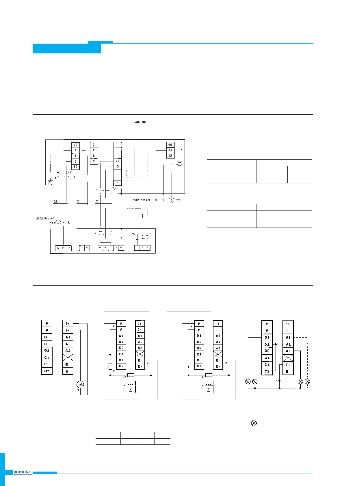
Connection of outputs
● Do not expose to heavy vibration.
● Mount the signal converter as close as possible to the primary
head.
● Use the supplied signal cable DS and data transmission cable Q,
standard length of each cable: 10 m / 30 ft.
Electrical connection IFS 4000 PF IFC 110 PF
Current output I
Ri= 15 – 500 Ω
Pulse output P
active
for electronic totalizer (EC)
for frequencies
≤ 1 kHz for frequencies > 1 kHz
R1 = 1kΩ/0.5 W
I ≤ 20 mA
R
i EC
> 100 kΩ
R2 / 0.2 W 10 kΩ 1k Ω 270 Ω
U
EC max
22 V 12 V 5 V
R = 1kΩ/0.35 W I ≤ 30 mA
Status outputs
D1 / D2 / A1 / A2 active
I ≤ 100 mA
e.g. signal indicator
IFC 110 PF
Max. permissible cable lengths
CField power supply cable, not included in supply, to
be provided by customer
DS Signal cable, with double shielding, 10 m / 30 ft
cable in supply
Q Data transmission cable,with single shielding,
3 x 0.75mm
2
/ 3 x 14 AWG, e.g. LiYCY,
10 m / 30 ft cable in supply,
max. permissible length 600m / 2000 ft
outputs / inputs
IFS 4000 PF
Max. permissible length Electrical conductivity
≤ 100m ≤ 330ft ≥ 50µS/cm **
≤ 200m ≤ 660ft ≥ 100 µS/cm **
≤ 600m ≤ 2000ft ≥ 400 µS/cm
Max. permissible length Type
≤ 150m ≤ 500ft 2 x 0.75 mm
2
2 x 18 AWG
≤ 300m ≤ 1000ft 2 x 1.50 mm
2
2 x 14 AWG
≤ 600m ≤ 2000ft 4 x 1.50 mm24 x 14 AWG
*internal connection, do not remove
** greater cable length on request
Please refer to pages 6 and 7 for technical data of the outputs and inputs.
Page 11
TIDALFLUX 11
TIDALFLUX
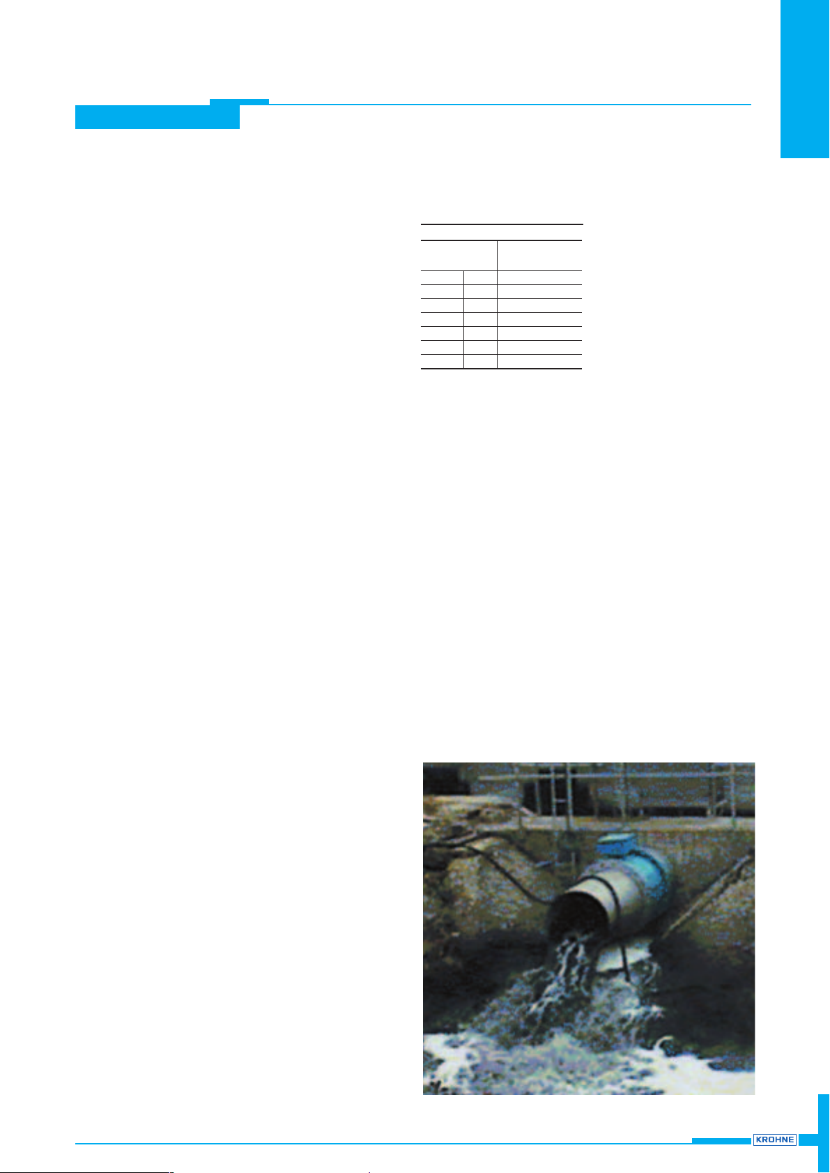
● Straight and unimpeded
inlet run > 5 x DN
}
(DN = meter size)
outlet run > 3 x DN
● Pipeline gradient < 1 %
● Turning the electrode axis out of the horizontal
< 2° (using DN 500/20” as an example:
< 10 mm/< 0.40” turn at flange edge)
● Electrical conductivity of the liquid product ≥ 50 µS/cm
● Operating pressure max. 10 bar/150 psig
● Process temperature – 5 to + 60°C (+ 23 to + 140°F)
● Ambient temperature – 25 to + 60°C (– 13 to + 140°F)
● To fit stud bolts and nuts
ensure there is sufficient room next to the pipe flanges.
● Vibration, support pipeline on both sides of the primary head.
● Use adapter pipes to permit axial shifting of counterflanges to
facilitate installation.
● Avoid strong electromagnetic fields
in the vicinity of the primary head.
● On isulated pipelines,
use grounding rings for measurement reasons.
Internal diameter of the EMF
Primary head
Meter size Measuring tube
dia. d
i
DN 200 8” 189 (7.44)
DN 250 10” 231 (9.09)
DN 300 12” 281 (11.06)
DN 350 14” 316 (12.44)
DN 400 16” 365 (14.37)
DN 500 20” 467 (18.39)
DN 600 24” 567 (22.32)
● Larger-sized particles,
trap by fitting a coarse screen upstream of the inlet run.
● Please order the application information.
● Provide an inspection and cleaning opening upstream of the
TIDALFLUX, in the direction of flow, so that the inside wall of the
measuring tube can be periodically checked for deposits and
cleaned if necessary, with water jet max. 10 bar.
Choice of location and installation in the pipeline
Page 12
TIDALFLUX
12
TIDALFLUX
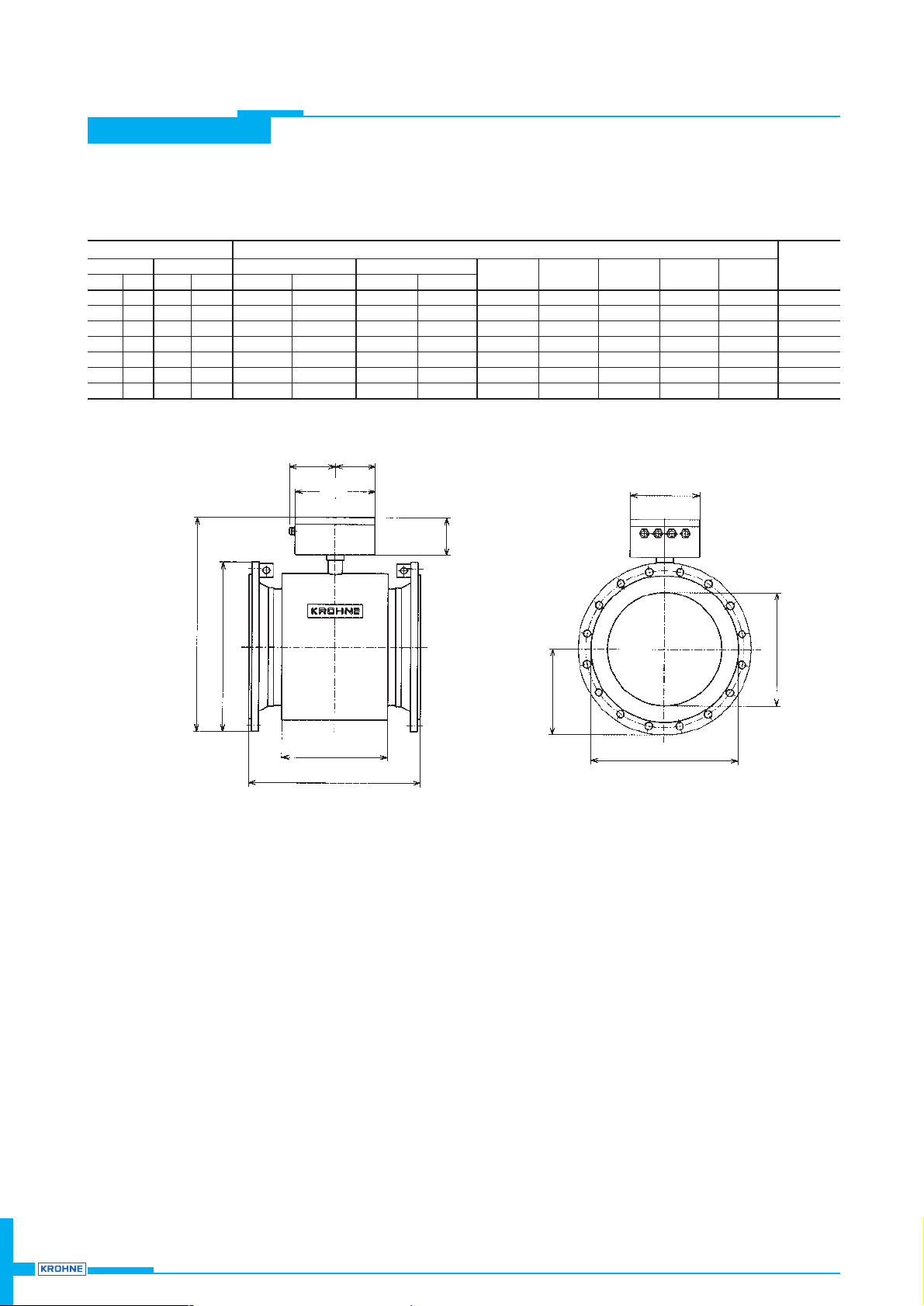
IFS 4000 PF Dimensions and weights
Dimension a without flange gaskets, not included with flowmeter, to be provided by customer
136
116
232
(5.35”)
(4.57”)
(9.13”)
202
(7.95”)
dia. c
dia. D
dia. Di
d
110
(4.33”)
+5 (+ 0.20”)
b 0
a ± 0.5 %
J
Meter size Dimensions in mm and inches Approx.
DIN 2501 ANSI B16.5 DIN 2501 ANSI B16.5 weight
DN mm PN inches Class a b a b Øc d j ØD ØDi kg lb
200 10 8 150lb 350 (13.78) 482 (18.98) 350 (13.78) 483 (19.02) 291 (11.46) 146 (5.75) 177 (6.97) 340 (13.39) 189 (7.44) 40 (90)
250 10 10 150 lb 400 (15.75) 530 (20.87) 400 (15.75) 535 (21.06) 331 (13.03) 166 (6.54) 205 (8.07) 395 (15.55) 231 (9.09) 54 (120)
300 10 12 150 lb 500 (19.69) 580 (22.83) 500 (19.69) 598 (23.54) 381 (15.00) 191 (7.52) 235 (9.25) 445 (17.52) 281 (11.06) 66 (145)
350 10 14 150 lb 500 (19.69) 618 (24.33) 700 (27.56) 646 (25.43) 428 (16.85) 214 (9.80) 306 (12.05) 505 (19.88) 316 (12.44) 95 (210)
400 10 16 150 lb 600 (23.62) 674 (26.54) 800 (31.50) 704 (27.72) 483 (19.02) 242 (9.53) 386 (15.20) 565 (22.24) 365 (14.37) 115 (255)
500 10 20 150 lb 600 (23.62) 778 (30.63) 800 (31.50) 806 (31.73) 585 (23.03) 293 (11.54) 386 (15.20) 670 (26.38) 467 (18.39) 145 (320)
600 10 24 150 lb 600 (23.62) 876 (34.49) 800 (31.50) 918 (36.14) 694 (27.32) 347 (13.66) 386 (15.20) 780 (30.71) 567 (22.32) 180 (400)
Dimensions > DN700 / > 28” on request
Page 13
13
TIDAFLUX
TIDAFLUX
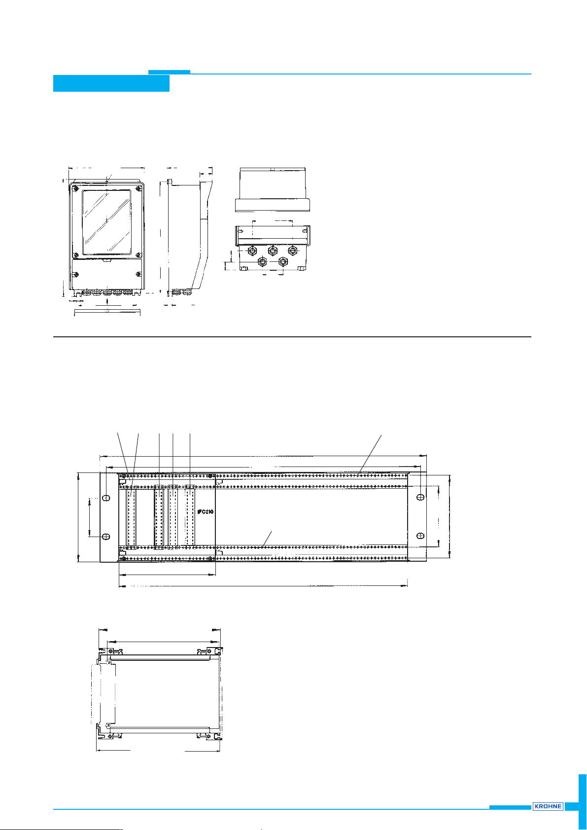
IFC 110 PF Dimensions and weights
Dimensions in mm (inches)
Weight approx. 4.5kg (10lb)
206 (8.11”)
approx. 123 (4.84”)
35
(1.38”)
A
160 (6.30”)
(0.35”)
326 (12.83”)
308 (12.13”)
56
(2.20”)
(0.83”)
(1.22”)
View “A”
dia. 9 (0.35”)
11 (0.43”
)
20 (0.79”)
112 (4.41”)
31
21
IFC 210 E-PF Dimensions and weights
Dimensions in mm and (inches)
Weight approx. 1.3 kg (2.9lb) 19” subrack 3 HE, dimensions to DIN 41494, part 5
Guide rail
Jack strips, mode “F”
to DIN 41612
Threaded hole (M2.5)
for front panels
1 TE = 5.08 mm
= 0.20 inches
1 HE = 44.17 mm
= 1.74 inches
Jack strips
XA primary head (Pages 12 + 13)
XB power supply (Pages 12 + 13)
XC outputs and inputs (Pages 8 + 9)
(XD) option RS 485 (Page 9)
XA (XD) XC XB
465.1 ± 1.6 (18.31” ± 0.06”)
3HE = 132.5 (5.22”)
57.1 (2.25”)
90 (3.54”)
122 (4.80”)
21 TE = 106.68 (4.20”)
84 TE = 426.72 (16.80”)
482.6 ± 0.4 (19” ± 0.016”)
Location holes
for jack strip
Mounting plane for
jack strips
Mounting plane for
front panels
175.24
+0.86
(6.90”
+0.034
”)
–0.14 – 0.006”
160 (6.30”)
Page 14
TIDAFLUX
14
TIDAFLUX
Page 15
15
TIDALFLUX
TIDALFLUX
 Loading...