

Page 1

GR/PRINTO
Variable area flowmeters
Vortex flowmeters
Flow controllers
Electromagnetic flowmeters
Ultrasonic flowmeters
Mass flowmeters
Level measuring instruments
Communications engineering
Engineering systems & solutions
©
KROHNE 08/2000 7.02378.21.00
UFM 610 P, UFM 600 T
Clamp-on ultrasonic
flowmeters
for liquids
Page 2

2
UFM 610 P, UFM 600 T
Clamp-on ultrasonic
flowmeters
for liquids
Efficient flowmetering and volume counting
of clean, homogeneous liquids with low gas
and solids contents.
Applications
● Demineralized water for cooling purposes
● Boiler feedwater in power stations
● Pretreated wastewater in sewage plants
● Checking other flowmeters
● Oil
● Acids
● Alkaline solutions
Advantages of measuring from the outside
● Non-contact measurement
● No construction of the pipe cross-section
● No additional pressure drop
● No interruption of the process
● Electrical conductivity, pressure, density,
etc. have no effect on measurements
● Easy to install
● No maintenance requirement
● Low power consumption
● Low operating costs
Diagonal mode (UFM 600 T and UFM 610 P)
Two ultrasonic transducers (sensors) are mounted on opposite sides
of the pipe at angle ϕ to the pipe axis.
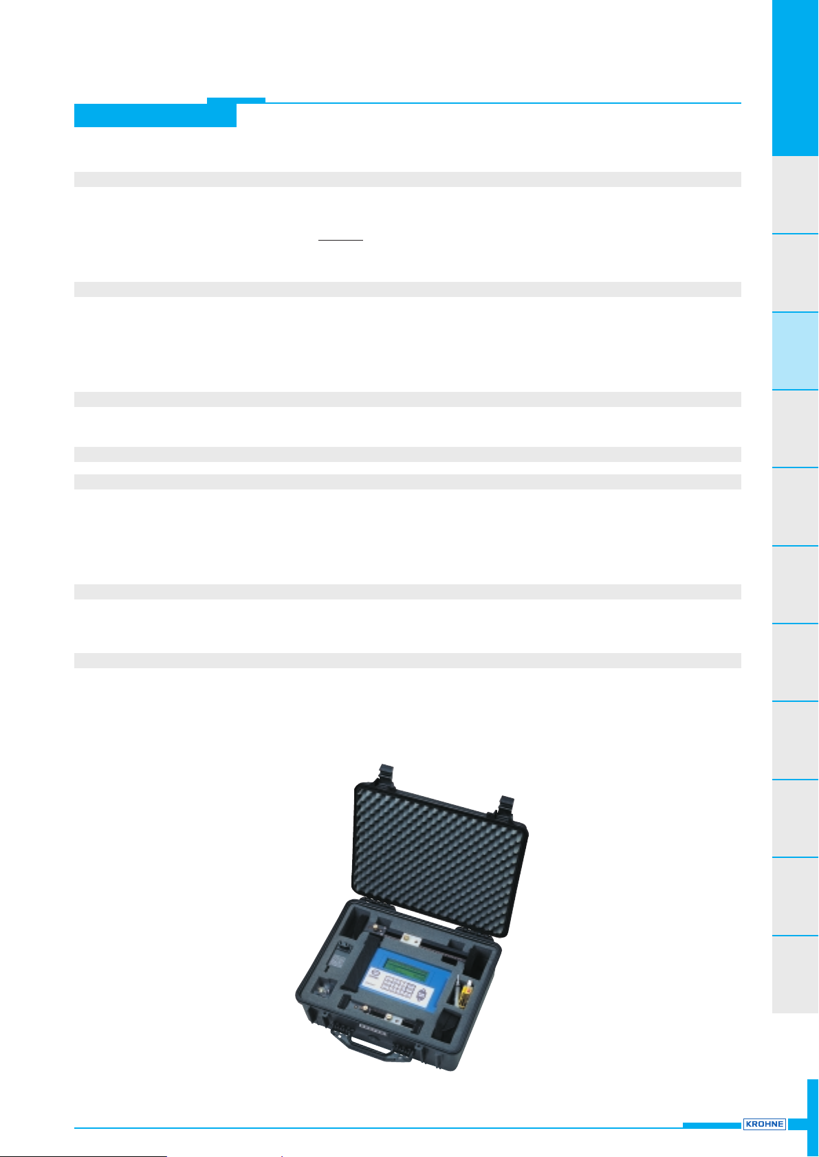
UFM 610 P portable device (in carrying case)
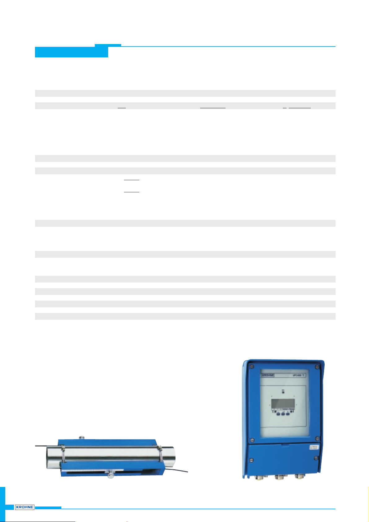
UFM 600 T wall mounted system
Configuration and function
● At the measuring point 2 ultrasonic sensors are attached to the
outside wall with the aid of a mounting device.
● Each sensor emits and receives sonic pulses that are digitally
converted in the signal converter.
● Data output in metric or US units via display, current, frequency and
status outputs, UFM 610 P also via RS 232 interface and PC.
Reflex mode (only UFM 610 P)
Two ultrasonic transducers (sensors) are mounted on the same side
of the pipe at an angle ϕ to the pipe axis.
A, B transmitter and receiver
L distance between sensors
v
m
average flow velocity of liquid
v
AB(vBA
) propagation speed (transit time)
of sound waves from point A
to point B, and B to point A
B A
AB
V
) V
AB (tAB
ϕ
v
m
BA (tBA
)
L
2
B
v
BA
v
m
v
AB
A
A
B
ϕ
L
Page 3

Background
Flowtubes
UFM 500
Clamp-on
UFM 600/610
Weld-om
UFM 800 W
Open channel
UFM 800 C
Gas-
flowtube
GFM 700
Custody
transfer
ALTOSONIC V
Calibration
Installation
notes
Sizing guide
Ordering
guide
3UFM 610 P / UFM 600 T
UFM 610 P / UFM 600 T
Systems
Versions
Application
Pipeline characteristics
Diameter (meter size)
Wall thickness of steel
Materials
Primary heads
Sensors
standard
standard
option
option
Mounting device
Technical data
Full-scale range
Error limits
Primary head
Signal converter
Application information
Dimensions
UFM 610 P
portable system
with CE approval to
EN 50081-1 and EN 50082-1
local display
current and pulse outputs
RS 232 interface
battery charger
volumetric flowrate measurement and
volume flow counting of liquids products
measurement in 1 or 2 flow directions
measurement of pipe wall temperature
13 – 5000 mm or
1
/2
” – 200”
< 75 mm / < 2.95”
metal, plastic and
internal / external coated pipes
(coating and liners fully bonded to pipewall)
2 ultrasonic sensors A, B, C
and/or D with mounting device
A: 13 – 89 mm ( 0.50” – 3.50”) inside
B: 90 – 1000 mm ( 3.54” – 40.00”) pipe
C: 300 – 2000 mm (12.00” – 80.00”) diaD: 1000 – 5000 mm (40.00” – 200.00”) meter
a mounting set consists of 1 adjustable sensor
and 1 fixed sensor with integrated pipe wall contact
temperature measurement (not for D sensors)
standard
option
A: chain –
B: chain magnets
C: chain magnets
D: webbing magnets
Page 4 – 7
4
4
4
5
6
7
UFM 600 T
wall mounted system
with CE approval to
EN 50081-1 and EN 50082-1
local display
current and pulse outputs
RS 232 interface
status output
volumetric flowrate measurement and
volume flow counting of liquids products
measurement in 1 or 2 flow directions
ultrasonic wave propagation time to
determine the liquid product
50 – 3000 mm or 2” – 120”
< 40 mm / < 1.60”
metal, plastic, ceramic, asbestos cement and
internal / external coated pipes
(coating and liners fully bonded to pipewall)
2 ultrasonic sensors RS 600
with ALTOCLAMP mounting device
for the total range
ALTOCLAMP mounting set with 2 sensors
and webbing straps
Page 8 – 11
8
8
8
9
10
11
}
Page 4

4 UFM 610 P / UFM 600 T
UFM 610 P
Responsibility for suitability and intended use of our instruments rests solely with the purchaser.
Technical data
Full-scale ranges
Selectable units m3, Liter, gallons, k gallons, US gallons per second, minute, hour, day and m/s, ft/s
Full-scale ranges Q
100%
Sensors Meter size min.
max.
A 13 – 89 mm / 0.5” – 3.5” 0.03 m/s (0.10 ft/s) 13.47 m/s (44.19 ft/s)
B 90 – 1000 mm / 3.54” – 40” 0.006 m/s (0.020 ft/s) 14.89 m/s (49.15 ft/s)
C 300 – 2000 mm / 12” – 80” 0.06 m/s (0.20 ft/s) 12.29 m/s (40.32 ft/s)
D 1000 – 5000 mm / 40” – 200” 0.008 m/s (0.026 ft/s) 7.27 m/s (23.85 ft/s)
Error limits
Measuring error (typical) v ≥ 1 m/s (≥ 3.3 ft/s): ± 2.0 % of measured value
v < 1 m/s (< 3.3 ft/s): ± 0.02 m/s (+ 0.066 ft/s)
Repeatability (typical) ± 0.5 % of measured value
UFS 610 ultrasonic transducer sensors
Product clean and homogeneous liquids
Temperature sensors A + B –20 to +200°C / –4 to +392°F
C –20 to +200°C / –4 to +392°F
D –20 to + 80°C / –4 to +176°F
Reynolds number Re > 10 000 (Re < 10 000 on request)
Solids and gas contents < 1 % by volume
Protection category
to IEC 529 / EN 60 529 IP 65 equivalent to NEMA 4/4X
Power supply 15 Volt from signal converter
Ambient temperature –25 to +60°C / –13 to +140°F
Connections / sensor cables coaxial cable RG 174 with LEMO connectors, length 3 m / 10 ft
Materials
Sensor housing Polyetheretherketone (PEEK)
Mounting device Aluminium, anodized
Page 5
Background
Flowtubes
UFM 500
Clamp-on
UFM 600/610
Weld-om
UFM 800 W
Open channel
UFM 800 C
Gas-
flowtube
GFM 700
Custody
transfer
ALTOSONIC V
Calibration
Installation
notes
Sizing guide
Ordering
guide
5UFM 610 P / UFM 600 T
UFM 610 P
UFC 610 P signal converter
Current output galvanically isolated, configurable ranges and values
Function continuous flow measurement
Current 0 – 20 mA / 4 – 20 mA / 0 – 16 mA
Time constant 3 – 100 s
Load Ri= 15 V in kΩ (e.g. 0.75 kΩ at 20 mA)
I
100%[mA]
Forward / reverse measurement (F/R) configurable
Pulse output configurable ranges and values
Function continuous flow totalization
Pulse rate for Q = 100% 1 pulse/s or 100 pulses/s
Amplitude 5 V
Pulse width 100 ms or 5 ms
Load R
i
1 kΩ
Forward / reverse measurement (F/R) settable
Low-flow cutoff
Function switches current and pulse outputs
Cutoff “on” and cutoff “off” values configurable between 0 – 1 m/s / 0 – 3.3 ft/s
Interface RS 232
Local display back-lit display
Display functions actual flowrate, totalizer, messages of outputs and errors, status data, temperature of pipe wall
Display units - flow m
3
/h, m3/min, m3/s, Liter/min, Liter/s, gallons/min, k gallons/h, US gallons/h and m/s, ft/s
- totalizer m
3
, Liter, gallons, US gallons
- temperature °C
Language of plain texts factory setting: English and German
can be changed to English and French (on floppy, diskette)
Power supply
Voltage 90 – 257 V AC
Frequency 50 / 60 Hz
Power consumption 9 VA
Carrying case
Material hard plastic
Ambient temperature – 25 to + 60°C / – 13 to + 140°F (electronics 0 to +60°C / + 32 to + 140°F)
Protection category
(IEC 529 / EN 60 529) IP 65 equivalent to NEMA 4/4X
Page 6
6 UFM 610 P / UFM 600 T
UFM 610 P
Mounting the UFS 610 ultrasonic sensors
● The clamp-on ultrasonic flowmeter is suitable for volumetric flowrate
measurement (and volume flow counting) in all metal, plastic, ceramic, asbestos cement and internally/externally coated pipelines.
Refer to pipeline data on page 3.
Coatings and liners must be fully bonded to the pipewall.
● Mount the flowmeter at a point where the pipe is always completely
filled with the liquid product, even at “zero” flow velocity.
● Solid and gas contents not to exceed 1% of volume.
Note:
Even in liquids that are virtually gas-free, large quantities of gas may
form if the liquid is allowed to expand before reaching the measuring
point, e.g. downstream of partially closed valves or small pump
outlets.
● For horizontal pipelines, position the sensors so that the measuring
beam is horizontal.
● The point of contact between the sensor and the pipeline must be
clean. If necessary, remove all traces of rust, flaked coatings, etc.
before mounting.
● Inlet run
... downstream of pump 15 x DN
... downstream of one or two
quarter bends 10 x DN
... downstream of reducer no additional
(reducing angle α/2 ≤ 4°) inlet run necessary
● Outlet run 5 x DN
(DN = nominal pipe dia.)
● The following physical parameters must be known: sound velocity
in the fluids, inside diameter of the pipe.
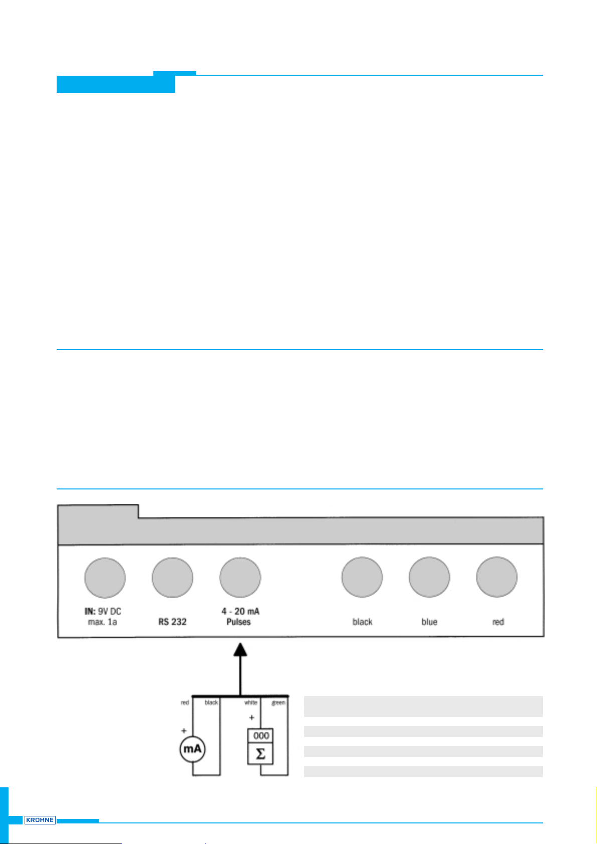
Electrical connection of UFC 610 P signal converter
● The two supplied sensor cables form the electrical connection
between sensors and signal converter.
● Note that length of sensor cables is 3 m (10 ft).
● Ambient temperature must be from –25 to +60°C (–13 to +140°),
therefore do not cover signal converter with heat-insulating materials,
and do not expose to strong sunlight or other heat sources.
● Avoid intensive vibration.
Technical data for output see Page 5.
Connection of sensor
RS 232 Colour of Plugs
interface cable 5-Pin 9-Pin
DSR red 1 (marked) 6
DTR black 24
GND (screen) – 35
TXD green 42
RXD white 53
Page 7
Background
Flowtubes
UFM 500
Clamp-on
UFM 600/610
Weld-om
UFM 800 W
Open channel
UFM 800 C
Gas-
flowtube
GFM 700
Custody
transfer
ALTOSONIC V
Calibration
Installation
notes
Sizing guide
Ordering
guide
7UFM 610 P / UFM 600 T
UFM 610 P
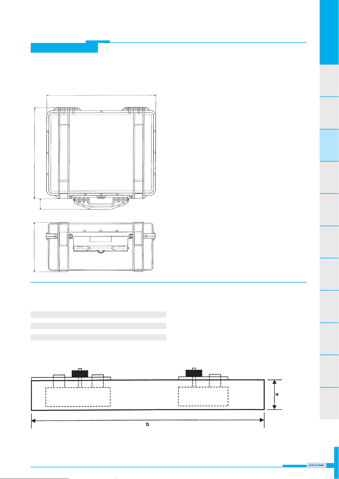
Dimensions and weights
Weight approx. 10.5 kg (23.5 lb)
Dimensions in mm (inches)
Sensors D on request
520 (20.47”)
430 (16.93”)
35
(1.38”)
220 (8.66”)
UFS 610 transducer sensors and mounting device
Sensor Dimensions mm (inches) Weight
ab kg (lb)
A 38 (1.50) 250 (9.84) 0.40 (1.0)
B + C 50 (1.97) 375 (14.76) 0.65 (1.5)
Page 8
8 UFM 610 P / UFM 600 T
Technical data
Full-scale ranges
Selectable units m3/h, liter/s, US gallons/min or user-defined unit
Full-scale range Q
100%
Unit lowest (min) highest (max)
Meter size DN in mm Q
100%
in m3/h = (DN / 100)2x 14.2 = DN2x 0.05
Meter sizes (DN) in inches Q
100%
in m3/h = DN2x 0.9 = DN2x 31.25
Q
100%
in US Gal/min = DN2x 3.9 = DN2x 138
Error limits
Measuring error ± 1 – 3% of measured value, depending on application
Repeatability
≤
0.2
in % of measured value with
vm in m/s (flow velocity)
Di x vm Di in m (inner tube diameter)
≤
24
in % of measured value with
vm in ft/s (flow velocity)
Di x vm Di in inch (inner tube diameter)
RS 600 ultrasonic transducer sensors
Product clean and homogeneous liquids
Temperature – 25 to + 120°C / – 13 to + 248°F
Reynolds number Re > 10 000
Solids and gas contents < 1 % by volumes (under operating conditions)
Protection category (IEC 529 / EN 60 529)
Standard IP 65 equivalent to NEMA 4 and 4X, sensors with BNC connectors
Special version IP 67 equivalent to NEMA 6, sensors with non-detachable connecting cable
Power supply 50 Volt from signal converter
Ambient temperature – 25 to + 60°C / – 13 to + 140°C
Sensor cable coaxial cable with BNC connectors, 5 m / 15 ft long (Option: 5 – 300 m / 15 – 900 ft long)
Materials
Sensor housing Brass nickel-plated
ALTOCLAMP
(mounting device) Aluminium anodized, for all pipe diameters
UFM 600 T
Responsibility for suitability and intended use of our instruments rests solely with the purchaser.
Page 9
Background
Flowtubes
UFM 500
Clamp-on
UFM 600/610
Weld-om
UFM 800 W
Open channel
UFM 800 C
Gas-
flowtube
GFM 700
Custody
transfer
ALTOSONIC V
Calibration
Installation
notes
Sizing guide
Ordering
guide
9UFM 610 P / UFM 600 T
UFM 600 T
UFC 600 T signal converter
Current output (term. 5/6) Galvanically isolated
Function
Continuous flowrate measurement or measurement of ultrasonic wave propagation
time to determine (composition of) the liquid product, can also be used at status output
Cur
rent
I0%for Q = 0% 0 to 16 mA
I
100%
for Q = 100% 4 to 20 mA
}
setting in increments of 1 mA
Lo
w-flow cutoff (SMU)
cutoff “on” value 1 to 19%
cutoff “off” value 2 to 20%
}
of Q
100%
, setting in 1% increments, independent of pulse output
Forward/re
verse measurements (F/R) direction identified via pulse output, see under “status output”
T
ime constant 0.04 to 3600 seconds, setting in increments of 1, 0.1 or 0.01 seconds
Max. load at I
100%
14 V
I
100%
[mA] in kohms (e.g. 0.7 kohms at 20 mA, 2.8 kohms at 5 mA)
Pulse output Galvanically isolated
Function continuous flow counting or measurement of ultrasonic wave propagation time
to determine (composition of) the liquid product, can also be used as status output, see below
Pulse rate for Q = 100% 10 to 36 000 000 pulses per hour
0.167 to 600 000 pulses per minute
0.0028 to 10 000 pulses per second (= Hz)
optionally in pulses per liter, m
3
or US gallons
Activ
e output short-circuit-proof
Terminals 4.1/4.2 for electromechanical (EMC) or electronic (EC) totalizers
Terminals 4/4.1/4.2 for electronic (EC) totalizers
Amplitude approx. 27 V DC
Load rating see Table “pulse width”
P
assiv
e output
Terminals 4/4.1 open collector for connection of active electronic totalizers (EC) or switchgear
Input voltage 5 to 30 V DC
Load current max. 100 mA
Load ratin
g of active output
Pulse width Frequency f at Q = 100% Load current Load
500 ms 0.0028 Hz < f ≤ 00001 Hz ≤ 150 mA ≥ 180 ohms
Pulse duty factor 1:1 0.0001 Hz < f ≤ 01000 Hz ≤ 25 mA ≥ 1000 ohms
160 µs 0.1000 Hz < f ≤ 02547 Hz ≤ 25 mA ≥ 1000 ohms
50 µs 0.2547 Hz < f ≤ 10000 Hz ≤ 25 mA ≥ 1000 ohms
Lo
w-flow cutoff (SMU)
cutoff “on” value 1 of 19%
cutoff “off” value 2 of 20%
}
of Q
100%
, setting in 1% increments, independent of current output
Forward/reverse measurements (F/R) direction identified via current output, see under “status output”
Time constant 0.04 seconds or same as current output
Status output Current output Pulse output
Connection ter
minals 5 + 6 4.1 + 4.2
V
oltage 24 V DC 24 V DC
Load cur
rent I
max
≤ 22 mA < 25 mA
I0%≤ 16 mA
Load
≤ 1.2 kohms > 1 kohms
Local display, at UFC 600 T only 3-line back-lit LCD
Display functions actual flowrate, propagation time of ultrasonic waves,
forward, reverse and sum totalizers (7-digit),
each can be set for continuous or sequential display, and output of error messages
Dis
play units
Actual flowrate liters, m3or US gallons per second, minute or hour,
1 user-defined unit (e.g. hectoliters per day or US million gallons per day)
Totalizers liters, m
3
or US gallons and 1 user-defined unit (e.g. hectoliters or US million gallons),
min. 1 year overflow time
Lan
guage of plain texts English, German, French, Dutch
Dis
play
1st line (top) 8-digit, 7-segment numeral and sign display, symbols for key acknowledgement
2nd line (middle) 10-character, 14-segment text display
3rd line (buttom) 5 markers
▼
to identify actual display
Power supply
AC version 85 – 264 V AC / P ≤ 10 VA
DC version 18 – 32 V DC / P ≤ 8 W
Housing
Material die-cast aluminium with polyurethane finish
Protection category (IEC 529 / EN 60 529) IP 65 equivalent to NEMA 4 and 4X
Hazardous duty version Zone 2, Artidor
Page 10
10 UFM 610 P / UFM 600 T
UFM 600 T
UFM 610 T
Mounting the RS 600 ultrasonic sensors
● The clamp-on ultrasonic flowmeter is suitable for volumetric flowrate
measurement (and volume flow counting) in all metal, plastic,
ceramic, asbestos cement and internally/externally coated pipelines.
Refer to pipeline data on page 3.
Coatings and liners must be fully bonded to the pipewall.
● Mount the flowmeter at a point where the pipe is always completely
filled with the liquid product, even at “zero” flow velocity.
● Not to exceed 1% by volume at flowing conditions.
Note:
Even in liquids that are virtually gas-free, large quantities of gas may
form if the liquid is allowed to expand before reaching the measuring
point, e.g. downstream of partially closed valves or small pump outlets.
● For horizontal pipelines, position the sensors so that the measuring
beam is also approximately horizontal.
UFM 610 T
Mounting the RS 600 ultrasonic sensors
● The point of contact between the sensors and the pipeline must
be clean. If necessary, remove all traces of rust, flaked coatings, etc.
before mounting.
● Inlet run
... downstream of pump 15 x DN
... downstream of one or two
quarter bends 10 x DN
... downstream of reducer no additional
(reducing angle α/2 = 4°) inlet run necessary
● Outlet run 5 x DN
(DN = nominal pipe dia.)
● The following physical parameters must be known: sound velocity
in the fluid inside diameter of the pipe.
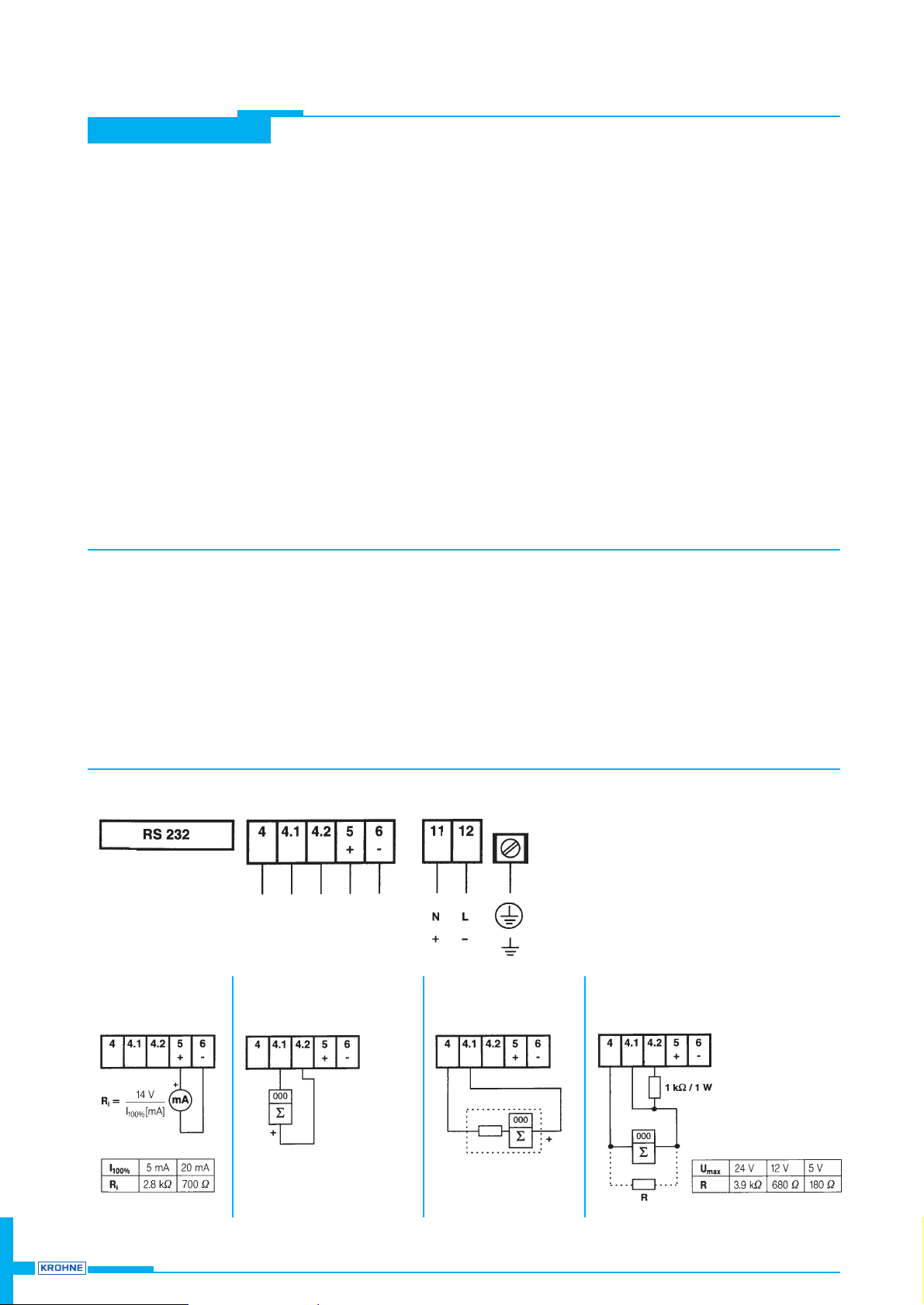
Mounting location and electrical connection of
UFC 600 T signal converter
● Mount UFC 600 T signal converter close to the measuring point
(RS 600 sensors).
● The two supplied sensor cables, fitted with BNC connectors, form
the electrical connection between sensors and signal converter.
● Note that length of sensor cables is 5 m (15 ft)
option: 5 – 100 m (15 – 300 ft).
Mounting location and electrical connection of
UFC 600 T signal converter
● Ambient temperature must be from –25 to +60°C (–13 to +140°F),
therefore do not cover signal converter with heat-insulating materials,
and do not expose to strong sunlight or other heat sources.
● Avoid intensive vibration.
Power supply
Interface
Outputs
PE 85 – 264 V AC
FE 18 – 32 V DC
Current output I Pulse output P
active
for EC and EMC
Pulse output P
passive
for active EC
Pulse output P
active
for EC
R
needed only for totalizers
with input voltages
U
max
< 30 V
U = 5 – 30 V DC
I ≤ 100 mA
U = approx. 27 V DC
I
max
and R
i
see table page 5
Page 11
Background
Flowtubes
UFM 500
Clamp-on
UFM 600/610
Weld-om
UFM 800 W
Open channel
UFM 800 C
Gas-
flowtube
GFM 700
Custody
transfer
ALTOSONIC V
Calibration
Installation
notes
Sizing guide
Ordering
guide
11UFM 610 P / UFM 600 T
UFM 600 T
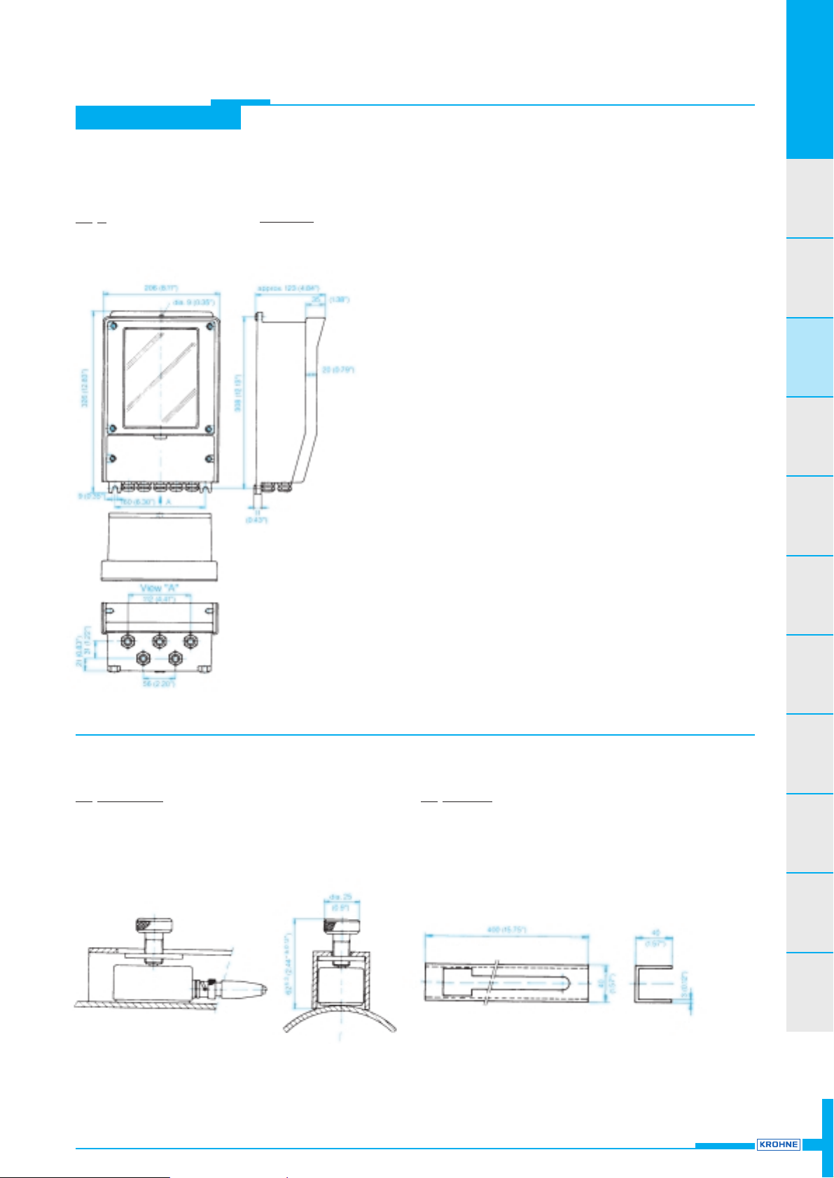
Dimensions and weights
UFC 600 T signal converter
W
eight
approx. 4.5 kg or 10 lbs
Dimensions
in mm (inches)
RS 600
Weight (2 sensors)
approx. 0.75 kg or 1.7 lbs
ALTOCLAMP
Weight (2 rails)
approx. 0.65 kg or 1.4 lbs
 Loading...