

Page 1
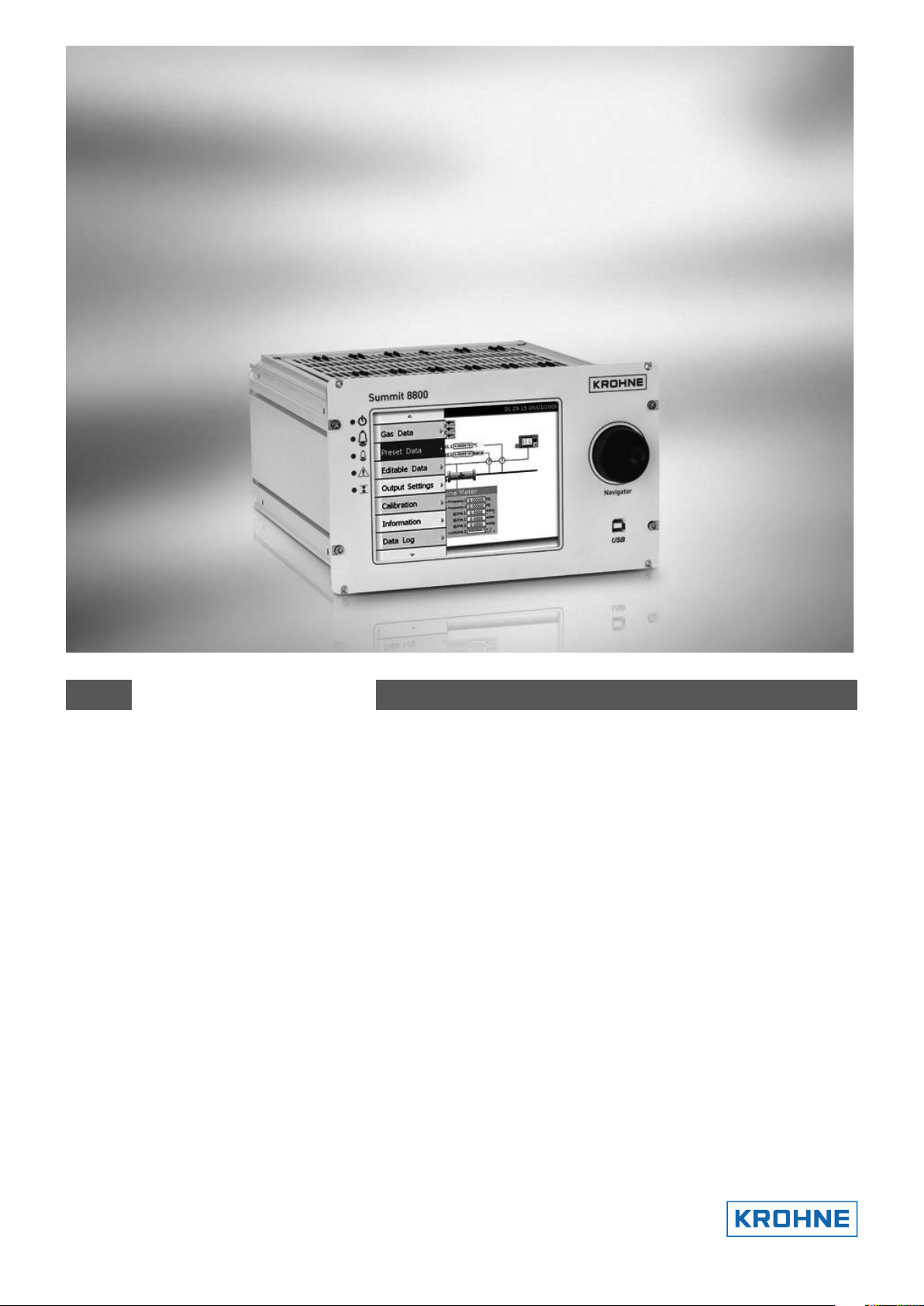
SUMMIT 8800
Flow Computer
Volume 1: Operation
Handbook
© KROHNE 08/2013 - MA SUMMIT 8800 Vol 1 R02 en
Page 2

SUMMIT 8800IMPRINT
All rights reserved. It is prohibited to reproduce this documentation, or any part thereof, without
the prior written authorisation of KROHNE Messtechnik GmbH.
Subject to change without notice.
Copyright 2013 by
KROHNE Messtechnik GmbH - Ludwig-Krohne-Str. 5 - 47058 Duisburg (Germany)
2 www.krohne.com 08/2013 - MA SUMMIT 8800 Vol1 R02 en
Page 3

SUMMIT 8800
CONTENTS
1 About this book 14
1.1 Volumes ............................................................................................................................. 14
1.2 Content Volume 1 .............................................................................................................. 14
1.3 Content Volume 2 .............................................................................................................. 14
1.4 Content Volume 3 .............................................................................................................. 15
1.5 Information in this handbook ............................................................................................ 15
2 General Information 16
2.1 Software versions used for this guide ...............................................................................16
2.2 Terminology and Abbreviations ......................................................................................... 16
3 Description 17
3.1 SUMMIT 8800 Hardware ....................................................................................................17
3.1.1 SUMMIT 8800 Flow Computer..................................................................................................17
3.1.2 SUMMIT 8800 basic functions .................................................................................................. 17
3.1.3 SUMMIT 8800 front panel layout .............................................................................................. 18
3.1.4 Rear Panel Layout .................................................................................................................... 19
3.1.5 Alarms & LED’s ........................................................................................................................19
3.1.6 Description of Hardware memory devices ...............................................................................20
3.2 Features SUMMIT 8800 .....................................................................................................21
3.2.1 Key Features .............................................................................................................................21
3.2.2 Calculations & Compliance standards .....................................................................................22
3.3 Integration possibilities ..................................................................................................... 22
3.3.1 System Integration ................................................................................................................... 22
3.3.2 Application integration ............................................................................................................. 23
4 Installation and Replacement 24
4.1 Mechanical Specifications ................................................................................................. 24
4.1.1 Mechanical Installation ............................................................................................................ 24
4.1.2 Panel Mounting ........................................................................................................................25
4.1.3 Rack mounting options ............................................................................................................ 26
4.1.4 Cable Assembly ......................................................................................................................26
4.2 Electrical Specifications .................................................................................................... 27
4.2.1 Electrical Installation ...............................................................................................................27
4.2.2 Earthing Requirements ............................................................................................................ 28
4.2.3 Fuses and Battery ....................................................................................................................28
4.2.4 Power Supply Terminals ..........................................................................................................29
4.2.5 Back Up Battery ......................................................................................................................30
4.2.6 Real time clock ......................................................................................................................... 33
08/2013 - MA SUMMIT 8800 Vol1 R02 en
www.krohne.com
3
Page 4

SUMMIT 8800CONTENTS
5 Hardware Details 34
5.1 Front Panel ........................................................................................................................ 34
5.1.1 Associated software .................................................................................................................34
5.2 Rear Panel ......................................................................................................................... 34
5.2.1 Removal of the Rear Panel ......................................................................................................34
5.2.2 Rear panel Mode Switches .......................................................................................................35
5.2.3 SD Card ..................................................................................................................................... 36
5.3 Standard hardware components .......................................................................................37
5.3.1 CPU Board Description ............................................................................................................38
5.3.2 PSU Board Description ............................................................................................................38
5.3.3 Auxiliary Board Description .....................................................................................................39
5.4 Optional Plug-in boards .................................................................................................... 40
5.4.1 Board Selection ........................................................................................................................40
5.4.2 Terminal Connectors ................................................................................................................ 41
5.4.3 Serial Communication Connection .......................................................................................... 42
5.5 Digital I/O Board ................................................................................................................ 42
5.5.1 Digital I/O Board 1 terminal connections.................................................................................43
5.5.2 Digital I/O Board 1 Settings ...................................................................................................... 43
5.6 Digital I/O Board 2 ............................................................................................................. 45
5.6.1 Digital /O Board 2 Terminal Connections ................................................................................45
5.6.2 Digital I/O Board 2 Settings ...................................................................................................... 46
5.7 Analog I/O Board ..............................................................................................................47
5.7.1 Analog I/O Board Terminal Connections ..................................................................................48
5.7.2 Analog I/O Board Settings ........................................................................................................ 48
5.8 Switch I/O Board ............................................................................................................... 50
5.8.1 Switch I/O Board Terminal Connections .................................................................................. 51
5.8.2 Switch I/O Board Settings ........................................................................................................51
5.9 Ethernet boards ................................................................................................................. 53
5.9.1 Ethernet Board Terminal Connections ...................................................................................54
5.9.2 Dual Ethernet Board Settings .................................................................................................. 55
5.9.3 Single Ethernet Board Settings ...............................................................................................55
5.10 DSfG Board ...................................................................................................................... 56
5.10.1 DSfG Board installation .......................................................................................................... 57
5.10.2 DSfG Board Terminal Connections ........................................................................................58
5.10.3 Boards block diagram ............................................................................................................59
6 Connecting To Field Devices 60
6.1 Transmitters & Transducers ............................................................................................. 60
6.1.1 HART Transmitter Input Connections ......................................................................................60
6.1.2 Digital Transmitter Input Connections.....................................................................................61
6.1.3 Digital Transmitter Output Connections ..................................................................................63
6.1.4 Analog Transmitter Input Connections .................................................................................... 64
6.1.5 Analog Transmitter Output Connection ................................................................................... 66
6.1.6 Direct RTD Input Connections .................................................................................................. 66
6.1.7 Pulse Bus ................................................................................................................................. 67
6.2 RS 232/RS485 Communications Connections .................................................................. 68
4 www.krohne.com 08/2013 - MA SUMMIT 8800 Vol1 R02 en
Page 5

SUMMIT 8800
CONTENTS
7 Operation 70
7.1 Initialising ......................................................................................................................... 70
7.2 Front Panel Operation ....................................................................................................... 70
7.2.1 Touch Panel ..............................................................................................................................70
7.2.2 Navigator .................................................................................................................................. 71
7.2.3 Navigation Controls Main Menu ............................................................................................... 71
7.2.4 Main Menu Display ................................................................................................................... 71
8 Calibration 83
8.1 Input Calibration ................................................................................................................ 83
8.1.1 HART Input .............................................................................................................................. 83
8.1.2 RTD Input .................................................................................................................................. 84
8.1.3 Analog Input Calibration ..........................................................................................................84
8.1.4 Digital Input .............................................................................................................................. 86
8.2 Output Calibration ............................................................................................................. 86
8.2.1 Analog Output ........................................................................................................................... 86
8.2.2 Digital Output ...........................................................................................................................87
9 Web Access 88
9.1 Login .................................................................................................................................. 88
9.2 The main page / display page ........................................................................................... 89
9.3 The information page ........................................................................................................ 90
9.4 The alarm page ................................................................................................................. 90
9.5 The Audit page: .................................................................................................................. 91
9.6 The active data page .......................................................................................................... 91
9.7 Download ........................................................................................................................... 92
10 Configuration Software 94
10.1 Introduction ..................................................................................................................... 94
10.1.1 Start the configurator ............................................................................................................. 94
10.1.2 Select the preferred engineering units .................................................................................. 95
10.1.3 Install an additional user .......................................................................................................95
10.2 USB Driver installation .................................................................................................... 97
10.3 Main functions of the configurator .................................................................................. 98
10.4 Connect to a Summit ....................................................................................................... 99
10.5 Working with configuration set-up’s ............................................................................. 101
10.5.1 Security ................................................................................................................................. 102
10.5.2 New configuration ................................................................................................................ 103
10.5.3 Load a configuration .............................................................................................................104
08/2013 - MA SUMMIT 8800 Vol1 R02 en
www.krohne.com
5
Page 6

SUMMIT 8800CONTENTS
10.5.4 Save a configuration ............................................................................................................. 106
10.5.5 Upload a configuration ......................................................................................................... 106
10.5.6 Download a configuration ....................................................................................................107
10.6 Edit menu ...................................................................................................................... 108
10.7 On-line (connection) menu ............................................................................................ 110
10.7.1 Read Setup ........................................................................................................................... 111
10.7.2 Read Alarms ......................................................................................................................... 111
10.7.3 Read Log Data ...................................................................................................................... 112
10.7.4 Read Data Reports ............................................................................................................... 113
10.7.5 Read Audit Log ..................................................................................................................... 114
10.7.6 Clear Data ............................................................................................................................. 115
10.7.7 Battery Status ....................................................................................................................... 115
10.7.8 Script Debug ......................................................................................................................... 115
10.7.9 Process Monitor ...................................................................................................................115
10.7.10 Check Threads .................................................................................................................... 115
10.7.11 Check Memory Pool ........................................................................................................... 116
10.7.12 Read Unit Information ........................................................................................................ 117
10.7.13 Log off and close ................................................................................................................ 117
11 Firmware 118
11.1 Introduction ................................................................................................................... 118
11.1.1 Firmware description ........................................................................................................... 118
11.1.2 Firmware Versions ...............................................................................................................119
11.2 Installation ..................................................................................................................... 119
11.3 Use of the wizard ........................................................................................................... 119
11.3.1 Upgrading firmware boot/main version ............................................................................... 120
12 Display Monitor 122
13 Appendix 1: Software Versions 123
13.1 Versions/ Revisions ....................................................................................................... 123
13.2 Current versions ............................................................................................................ 123
13.2.1 Latest version 0.35.0.0 .........................................................................................................123
13.2.2 Approved version MID2.4.0.0 ................................................................................................ 123
14 Appendix 2: Signal Allocation Forms 125
14.1 Example ......................................................................................................................... 125
14.1.1 Digital /O Board 1 Terminal Connections ............................................................................126
14.1.2 Digital /O Board 2 Terminal Connections ............................................................................127
14.1.3 Analog /O Board Terminal Connections ...............................................................................128
14.1.4 Switch Board Terminal Connections ....................................................................................129
14.1.5 Dual Ethernet Board Terminal Connections ........................................................................130
6 www.krohne.com 08/2013 - MA SUMMIT 8800 Vol1 R02 en
Page 7

SUMMIT 8800
14.1.6 Single Ethernet Board Terminal Connections .....................................................................131
14.1.7 DSfG Board Terminal Connections ......................................................................................132
CONTENTS
15 Appendix 3: Technical Data 133
15.1 General .......................................................................................................................... 133
15.2 Inputs ............................................................................................................................. 133
15.3 Outputs .......................................................................................................................... 134
15.3.1 Communication .................................................................................................................... 134
15.3.2 Power Supply ........................................................................................................................ 135
15.4 Data sheet ...................................................................................................................... 135
15.4.1 Ordering Options ..................................................................................................................138
15.4.2 Replacement Parts ...............................................................................................................139
16 Appendix 4: Install The Configurator 140
08/2013 - MA SUMMIT 8800 Vol1 R02 en
www.krohne.com
7
Page 8

SUMMIT 8800TABLE OF FIGURES
Figure 1 Front view of Summit 8800 ................................................................. 18
Figure 2 Rear view of SUMMIT 8800 ................................................................. 19
Figure 3 LED indicators ........................................................................... 19
Figure 4 SUMMIT 8800 system integration overview ................................................... 23
Figure 5 Stream application integration ............................................................. 23
Figure 6 Dimensions & Outlines .................................................................... 25
Figure 7 Panel mounted installations. . . . . . . . . . . . . . . . . . . . . . . . . . . . . . . . . . . . . . . . . . . . . . . . . . . . . . . . . . . . . . . . 25
Figure 8 Rack mounting kit ........................................................................ 26
Figure 9 Rack mounted installation ................................................................. 26
Figure 10 Cable assembly ......................................................................... 27
Figure 11 Fuse F1 (left) en F2 (right) ................................................................ 29
Figure 12 Power & M4 earth connections ............................................................ 30
Figure 13 Configurator good and bad battery indicator ................................................. 31
Figure 14 Bad battery indicator on front panel ........................................................ 31
Figure 15 Totalizers enter field ..................................................................... 32
Figure 16 Auxiliary board ......................................................................... 32
Figure 17 Front panel of SUMMIT 8800 & USB port .................................................... 34
Figure 18 Rear panel of SUMMIT 8800 and removal screws ............................................. 35
Figure 19 Mode Switch settings .................................................................... 35
Figure 20 System information screen ............................................................... 36
Figure 21 Illustration of inserted SD card ............................................................ 37
Figure 22 Modular design chassis .................................................................. 37
Figure 23 Board slots with mother board & rear view panel ............................................. 38
Figure 24 Power supply unit ....................................................................... 38
Figure 25 PSU board components ................................................................... 39
Figure 26 Auxiliary board .......................................................................... 39
Figure 27 Auxiliary board components ............................................................... 40
Figure 28 Typical I/O board ........................................................................ 40
Figure 29 Illustration method of cable insertion into clamp ............................................. 41
Figure 30 Serial port I/O boards rear terminal pin allocation ............................................ 42
Figure 31 Digital I/O board 1 rear terminal pin allocation ............................................... 43
Figure 32 Digital I/O board digital input link setting .................................................. 44
Figure 33 Digital I/O board HART loop link settings ......................................... 44
Figure 34 Digital I/O board RS485 termination link setting ....................................... 44
Figure 35 Digital I/O board 2 rear terminal pin allocation ............................................... 45
Figure 36 Digital I/O board digital input link setting ................................................... 46
Figure 37 Digital I/O board 2 HART loop link settings ............................................. 46
Figure 38 Digital I/O board 2 RS485 termination link setting ............................................ 47
Figure 39 Analog I/O board rear terminal pin allocation ................................................ 48
Figure 40 Analog I/O board digital input link settings ................................................ 49
Figure 41 Analog I/O board HART loop and I/O function link settings ..................................... 49
Figure 42 Analog I/O board RS485 termination link setting ............................................. 50
Figure 43 Switch I/O board rear terminal pin allocation ................................................ 51
Figure 44 Switch I/O board digital input link setting .............................................. 52
Figure 45 Switch I/O board digital input link settings ................................................... 52
Figure 46 Switch I/O board RS485 termination link settings ............................................. 53
Figure 47 Switch I/O board digital input / output link settings ........................................... 53
Figure 48 Ethernet boards rear terminal pin allocation ................................................. 54
Figure 49 Dual Ethernet communication board link setting ............................................. 55
Figure 50 Communication board link setting .......................................................... 56
Figure 51 DSfG communication board ............................................................... 57
Figure 52 DSfG communication installation .......................................................... 57
Figure 53 DSfG boards block diagram ............................................................... 59
Figure 54 Typical HART transmitter connections ...................................................... 60
Figure 55 HART multidrop ......................................................................... 61
Figure 56 Digital Input internal circuit ............................................................... 62
Figure 57 Digital input density transducer ............................................................ 62
Figure 58 Digital input status optocoupler ............................................................ 63
Figure 59 Digital input pulse status ................................................................. 63
Figure 60 Digital output valve solenoid .............................................................. 63
Figure 61 Typical analog input connections ........................................................... 64
Figure 62 Analog input active transmitter loop ........................................................ 64
Figure 63 Analog input internal circuit ............................................................... 65
Figure 64 Analog input transmitter isolator loop ...................................................... 65
Figure 65 Analog input passive transmitter loop ...................................................... 65
Figure 66 Analog output passive actuator ............................................................ 66
Figure 67 Direct RTD connection .................................................................... 66
Figure 68 Pulse bus loop .......................................................................... 67
Figure 69 Start/stop signals loop ................................................................... 68
Figure 70 Internal RS485 Termination network ....................................................... 69
Figure 71 RS485 multidrop ...................................................................... 69
8 www.krohne.com 08/2013 - MA SUMMIT 8800 Vol1 R02 en
Page 9

SUMMIT 8800
Figure 72 SUMMIT 8800 initialization ............................................................... 70
Figure 73 Parameter highlighted by Navigator ........................................................ 71
Figure 74 Parameter selected by Navigator .......................................................... 71
Figure 75 Screen navigation and control indicators .................................................... 71
Figure 76 Main menu parameters ................................................................... 72
Figure 77 Edit mode login screen ................................................................... 73
Figure 78 Enter values screen ...................................................................... 74
Figure 79 Exit edit screen ......................................................................... 74
Figure 80 Calibration menu ........................................................................ 75
Figure 81 Alarm page ............................................................................. 76
Figure 82 Audit Log Example ...................................................................... 77
Figure 83 Audit log trail ........................................................................... 77
Figure 84 Supervisory screen display ............................................................... 78
Figure 85 Supervisory Mode Enabled ................................................................ 78
Figure 86 System information screen ............................................................... 79
Figure 87 Display settings screen ................................................................... 80
Figure 88 Display test screen ...................................................................... 81
Figure 89 Touch screen calibration .................................................................. 82
Figure 90 Touch Screen Calibration pages ........................................................... 82
Figure 91 Calibrate HART screen ................................................................... 83
Figure 92 RTD Input calibration screen .............................................................. 84
Figure 93 Calibrate analog input .................................................................... 85
Figure 94 Calibration selection screen ............................................................... 85
Figure 95 Analog output calibration screen ........................................................... 87
Figure 96 Website login ........................................................................... 88
Figure 97 Main Page .............................................................................. 89
Figure 98 Main page bar chart ..................................................................... 89
Figure 99 Information page ........................................................................ 90
Figure 100 Alarm page ............................................................................ 90
Figure 101 Audit log .............................................................................. 91
Figure 102 Active data page ........................................................................ 91
Figure 103 Downloading CSV file ................................................................... 92
Figure 104 Import wizard .......................................................................... 93
Figure 105 Finishing the wizard in Excel ............................................................. 93
Figure 106 Configurator desktop icon ............................................................... 94
Figure 107 User login screen ....................................................................... 94
Figure 108 Menu Configurator software ............................................................. 95
Figure 109 Appearance ........................................................................... 95
Figure 110 User creation screen .................................................................... 96
Figure 111 User access level ....................................................................... 96
Figure 112 24V input power ........................................................................ 97
Figure 113 USB port .............................................................................. 97
Figure 114 Driver recognition message .............................................................. 97
Figure 115 Menu Configurator software ............................................................. 98
Figure 116 Connection list ......................................................................... 99
Figure 117 Manual connection list .................................................................. 100
Figure 118 Reading setup ......................................................................... 100
Figure 119 Connection menu ....................................................................... 101
Figure 120 Fully secure error message .............................................................. 102
Figure 121 Operating dipswitch settings ............................................................. 103
Figure 122 Select version .......................................................................... 103
Figure 123 Select Run type ........................................................................ 104
Figure 124 Load configuration file .................................................................. 105
Figure 125 Load set-up configuration ............................................................... 105
Figure 126 Save configuration ...................................................................... 106
Figure 127 Edit online window ..................................................................... 107
Figure 128 Edit off-line menu ...................................................................... 107
Figure 129 Connection list ......................................................................... 108
Figure 130 Download configuration process .......................................................... 108
Figure 131 Edit offline ............................................................................ 109
Figure 132 Connection menu ....................................................................... 111
Figure 133 Alarm window ......................................................................... 112
Figure 134 Data log selection ...................................................................... 112
Figure 135 Data log window ........................................................................ 113
Figure 136 Data report window ..................................................................... 114
Figure 137 Audit log window ....................................................................... 114
Figure 138 Configurator good battery status .......................................................... 115
Figure 139 Check threads display ................................................................... 116
Figure 140 Check memory pool display .............................................................. 116
Figure 141 Firmware illustration ................................................................... 119
Figure 142 Upgrade mode switch ................................................................... 120
TABLE OF FIGURES
08/2013 - MA SUMMIT 8800 Vol1 R02 en
www.krohne.com
9
Page 10

SUMMIT 8800TABLE OF FIGURES
Figure 143 USB cable port ......................................................................... 120
Figure 144 Input power ........................................................................... 120
Figure 145 Update wizard windows ................................................................. 121
Figure 146 Configurator Wizard screen .............................................................. 140
Figure 147 Configurator file location ................................................................ 140
Figure 148 Configurator program location ........................................................... 141
Figure 149 Configurator install features ............................................................. 141
Figure 150 Software installation process ............................................................. 142
Figure 151 Completion window ..................................................................... 142
Figure 152 Add user window ....................................................................... 142
Figure 153 Edit user window ....................................................................... 143
10 www.krohne.com 08/2013 - MA SUMMIT 8800 Vol1 R02 en
Page 11

SUMMIT 8800
Table 1 Location of fuses on PSU .............................................................................................................................................39
Table 2 Boards with available Inputs & Outputs ......................................................................................................................41
Table 3 Digital I/O board 1 link settings ...................................................................................................................................44
Table 4 HART loop settings on digital I/O board 1 ....................................................................................................................44
Table 5 Serial settings on digital I/O board 1 ...........................................................................................................................44
Table 6 Digital I/O board 2 settings ..........................................................................................................................................46
Table 7 HART loop settings on digital I/O board 2 ....................................................................................................................46
Table 8 Serial settings on digital I/O board 2 ...........................................................................................................................47
Table 9 Digital input link settings on analog board ..................................................................................................................49
Table 10 HART and I/O functions settings on analog board ....................................................................................................49
Table 11 Serial settings on analog I/O board ...........................................................................................................................50
Table 12 Switch I/O digital input settings .................................................................................................................................52
Table 13 Switch I/O board digital settings ................................................................................................................................52
Table 14 Serial settings on switch I/O board ............................................................................................................................53
Table 15 Switch I/O board digital settings ................................................................................................................................53
Table 16 Communication board configuration .........................................................................................................................53
Table 17 Dual Ethernet serial settings .....................................................................................................................................55
Table 18 Dual Ethernet port LED indicators ............................................................................................................................55
Table 19 Single Ethernet serial settings ..................................................................................................................................56
Table 20 Single Ethernet port LED indicators ..........................................................................................................................56
Table 21 Digital transmitter reference voltage and resistance ...............................................................................................61
TABLES
08/2013 - MA SUMMIT 8800 Vol1 R02 en
www.krohne.com
11
Page 12
SUMMIT 8800ABOUT THIS HANDBOOK01
12 www.krohne.com 08/2013 - MA SUMMIT 8800 Vol1 R02 en
Page 13

SUMMIT 8800
IMPORTANT INFORMATION
KROHNE Oil & Gas pursues a policy of continuous development and product improvement. The
Information contained in this document is, therefore subject to change without notice. Some
display descriptions and menus may not be exactly as described in this handbook. However, due
the straight forward nature of the display this should not cause any problem in use.
To the best of our knowledge, the information contained in this document is deemed accurate
at time of publication. KROHNE Oil & Gas cannot be held responsible for any errors, omissions,
inaccuracies or any losses incurred as a result.
In the design and construction of this equipment and instructions contained in this handbook,
due consideration has been given to safety requirements in respect of statutory industrial regulations.
ABOUT THIS HANDBOOK
01
Users are reminded that these regulations similarly apply to installation, operation and maintenance, safety being mainly dependent upon the skill of the operator and strict supervisory
control.
08/2013 - MA SUMMIT 8800 Vol1 R02 en
www.krohne.com
13
Page 14

1. About this book
1.1 Volumes
This is Volume 1 of 3 of the SUMMIT 8800 Handbook:
Volume 1
Volume 1 is targeted to the electrical, instrumentation and maintenance engineer
This is an introduction to the SUMMIT 8800 flow computer, explaining its architect and layout providing the user with familiarity and the basic principles of build. The volume describes the
Installation and hardware details, its connection to field devices and the calibration.
The manual describes the operation via its display, its web site and the configuration software.
Also the operational functional of the Windows software tools are described, including the configurator, the Firmware wizard and the display monitor.
Volume 2
Volume 2 is targeted to the metering software configuration by a metering engineer.
The aim of this volume is to provide information on how to configure a stream and the associated hardware.
The handbook explains the configuration for the different metering technologies, including meters, provers, samplers, valves, redundancy etc.. A step by step handbook using the Configurator
software, on the general and basic setup to successfully implement flow measurement based on
all the applications and meters selections within the flow computer.
SUMMIT 8800ABOUT THIS HANDBOOK01
Volume 3
Volume 3 is targeted to the software configuration of the communication.
The manual covers all advance functionality of the SUMMIT 8800 including display configuration,
reports, communication protocols, remote access and many more advance options.
1.2 Content Volume 1
Volume 1 concentrates on the daily use of the flow computer
• Chapter 2: Basic functions of the flow computer
• Chapter 3: General information on the flow computer
• Chapter 4: Installation and replacement of the flow computer
• Chapter 5: Hardware details on the computer, its components and boards
• Chapter 6: Connecting to Field Devices
• Chapter 7: Normal operation via the touch screen
• Chapter 8: How to calibration the unit
• Chapter 9: Operation via the optional web site
• Chapter 10: Operational functions of the configuration software, more details in volume 2
• Chapter 11: How to update the firmware
• Chapter 12: Display monitor software to replicate the SUMMIT 8800 screen on a PC and make
screen shots
1.3 Content Volume 2
Volume 2 concentrates on the software for the flow computer.
• Chapter 2: General information on the software aspects of the flow computer
• Chapter 3: Details on metering principles
• Chapter 4: Basic functions of configurator
• Chapter 5: Configuration of the hardware of the boards
• Chapter 6: Stream configuration
• Chapter 7: Run switching
• Chapter 8: Watchdog
14 www.krohne.com 08/2013 - MA SUMMIT 8800 Vol1 R02 en
Page 15

SUMMIT 8800
• Chapter 9: Configure a station
• Chapter 10: Configure a prover or master meter
• Chapter 11: Configure valves
• Chapter 12: Configure a sampler
• Chapter 13: Set-up batching
• Chapter 14: Set two flow computers in redundant configuration
1.4 Content Volume 3
Volume 3 concentrates on the configuration of the SUMMIT 8800
• Chapter 3; Configurator software
• Chapter 4: Date & Time
• Chapter 5: Data Logging
• Chapter 6: Display and web access
• Chapter 7: Reporting
• Chapter 8: Communication
• Chapter 9: General Information
1.5 Information in this handbook
ABOUT THIS HANDBOOK
01
The information in this handbook is intended for the integrator who is responsible to setup and
configure the SUMMIT 8800 flow computer for Liquid and or Gas and or Steam application:
Integrators (hereafter designated user) with information of how to install, configure, operate and
undertake more complicated service tasks.
This handbook does not cover any devices or peripheral components that are to be installed and
connected to the SUMMIT 8800 it is assumed that such devices are installed in accordance with
the operating instructions supplied with them.
Disclaimer
KROHNE Oil & Gas take no responsibility for any loss or damages and disclaims all liability for
any instructions provided in this handbook. All installations including hazardous area installations are the responsibility of the user, or integrator for all field instrumentation connected to
and from the SUMMIT 8800 Flow computer.
Trademarks
SUMMIT 8800 is a trade mark of KROHNE Oil & Gas.
Notifications
KROHNE Oil & Gas reserve the right to modify parts and/or all of the handbook and any other
documentation and/ or material without any notification and will not be held liable for any damages or loss that may result in making any such amendments.
Copyright
This document is copyright protected.
KROHNE Oil & Gas does not permit any use of parts, or this entire document in the creation of
any documentation, material or any other production. Prior written permission must be obtained
directly from KROHNE Oil & Gas for usage of contents. All rights reserved.
Who should use this handbook?
This handbook is intended for the integrator or engineer who is required to configure the flow
computer for a stream including devices connected to it.
Versions covered in this handbook
All Versions
08/2013 - MA SUMMIT 8800 Vol1 R02 en
www.krohne.com
15
Page 16

2. General Information
2.1 Software versions used for this guide
This handbook is based on the software versions as mentioned in Appendix 1: software versions
2.2 Terminology and Abbreviations
AGA American Gas Association
API American Petroleum Institute
Communication board Single or dual Ethernet network board
Configurator Windows software tool to configure and communicate to the SUMMIT 8800
CP Control Panel
CPU Central Processing Unit
CRC32 Cyclic Redundancy Check 32 bits. Checksum to ensure validity of information
FAT Factory Acceptance Test
FDS Functional Design Specification
HMI Human-Machine Interface
HOV Hand Operated Valve
I/O Input / Output
ISO International Standards Organization
KOG KROHNE Oil and Gas
KVM Keyboard / Video / Mouse
MOV Motor Operated Valve
MSC Metering Supervisory Computer
MUT Meter Under Test
Navigator 360 optical rotary dial
PC Personal Computer
PRT Platinum Resistance Thermometers
PSU Power Supply Unit
PT Pressure Transmitter
Re-try Method to repeat communication a number of times before giving an alarm
RTD: Resistance Temperature Device
Run: Stream/Meter Run
SAT Site Acceptance Test
SUMMIT 8800 Flow computer
Timestamp Time and date at which data is logged
Time-out Count-down timer to generate an alarm if software stopped running
TT Temperature Transmitter
UFC Ultrasonic Flow Converter
UFM Ultrasonic Flow Meter
UFP Ultrasonic Flow Processor (KROHNE flow computer )
UFS Ultrasonic Flow Sensor
VOS Velocity of Sound
ZS Ball detector switch
XS Position 4-way valve
XV Control 4-way valve
SUMMIT 8800GENERAL INFORMATION02
16 www.krohne.com 08/2013 - MA SUMMIT 8800 Vol1 R02 en
Page 17
SUMMIT 8800
3. Description
3.1 SUMMIT 8800 Hardware
3.1.1 SUMMIT 8800 Flow Computer
The SUMMIT 8800 is an advanced hydrocarbon computing precision instrument for measuring
and calculating flow of gases and liquids, using various connected metering devices, including
transmitters, transducers with internal algorithms to International standards.
The SUMMIT 8800 is configured using the supplied configurator running on a PC or laptop.
Initially there are a number of basic decisions that need to be made in order to configure the device. The configurator will guide the operator through the various choices that need to be made.
Primary important objectives are defined by types:
Device type Standard run and/or liquid prover or gas prover
Measurement type Gas turbine, rotary or other pulse meter type
Gas ultrasonic Meter
Gas differential pressure orifice or Venturi type
Gas Coriolis
Liquid turbine or other pulse meter type
Liquid ultrasonic meter
Liquid Coriolis meter
Steam ultrasonic meter
DESCRIPTION
03
Number of streams 1, 2, 3, 4 or 5 plus prover
Secondary transducer
types
Secondary transducer
connections
Pressure
Temperature
Density
Relative Density
Differential Pressure
Gas Component
BS&W
HART
4-20mA
PRT/RTD
Digital – pulse/frequency Input
Serial Connection.
3.1.2 SUMMIT 8800 basic functions
The SUMMIT 8800 flow computer comprises a standard size half width 19 inch rack which contains plug-in printed circuit boards connected to a mother board. The power supply is +24 VDC.
It is designed to calculate the total energy, volume and instantaneous flow rates of gas and alternatively liquids. Calculation is carried out using inputs from pulse generating turbine meters,
08/2013 - MA SUMMIT 8800 Vol1 R02 en
www.krohne.com
17
Page 18
SUMMIT 8800DESCRIPTION03
ultrasonic gas meters or from differential pressure measurement across orifice plates together
with temperature sensors and transmitters for line pressure.
The SUMMIT 8800 uses pre-set or active input values of relative density, gas composition data
and heating value, active values can be received directly from a gas chromatograph or can be
written serially from a supervisory system.
The flow of gas is calculated using gas compressibility (Z factor) methods selected from a list
of which includes AGA 8, ISO 12213 and AGA 3 NX19 as well as fixed factors for certain applications. As an alternative, the flow of gas can be calculated using a transducer input for line
density.
The flow of liquid is calculated using fixed or measured factors for density and relative density
and correction based upon measured temperature and pressure of the liquid in accordance with
API standard chapters 11.1, 11.2.1M, 11.2.2M & 12.
The flow computer has the facility of both high and low alarms on all active input signals, the
alarms can be selected to enable a default value to be used in flow calculation for the parameter
in the alarm condition. Indication is given of the time of occurrence and clearance of the alarm
state, alarm output signals are also provided. It uses digital communication to the differential
pressure, pressure and temperature transmitters using the HART protocol eliminating the need
for calibration of the flow computer. This feature also eliminates the errors in flow measurement due to ambient temperature effects on the flow computer, only the temperature coefficient
of the transmitters contribute to the error.
Alternatively the SUMMIT 8800 can be operated from transmitters that supply a 4–20mA current output and also direct from a 100 ohm platinum resistance thermometer for temperature
measurement, these types of input are measured using analogue inputs and a high resolution
A-D converter. The analogue inputs are calibrated using software.
The SUMMIT 8800 has 3 optional RS232/RS485 serial data ports which can provide Modbus RTU
or ASCII communication protocols for operation with system devices and a serial ASCII protocol
compatible with most printers.
The SUMMIT 8800 has 2 optional Ethernet port which can provide TCP/IP or Modbus over TCP/
IP protocols for supervisory system communication, and includes 5 programmable solid state
pulse/alarm outputs and 2 analogue output signals for process monitoring and status control.
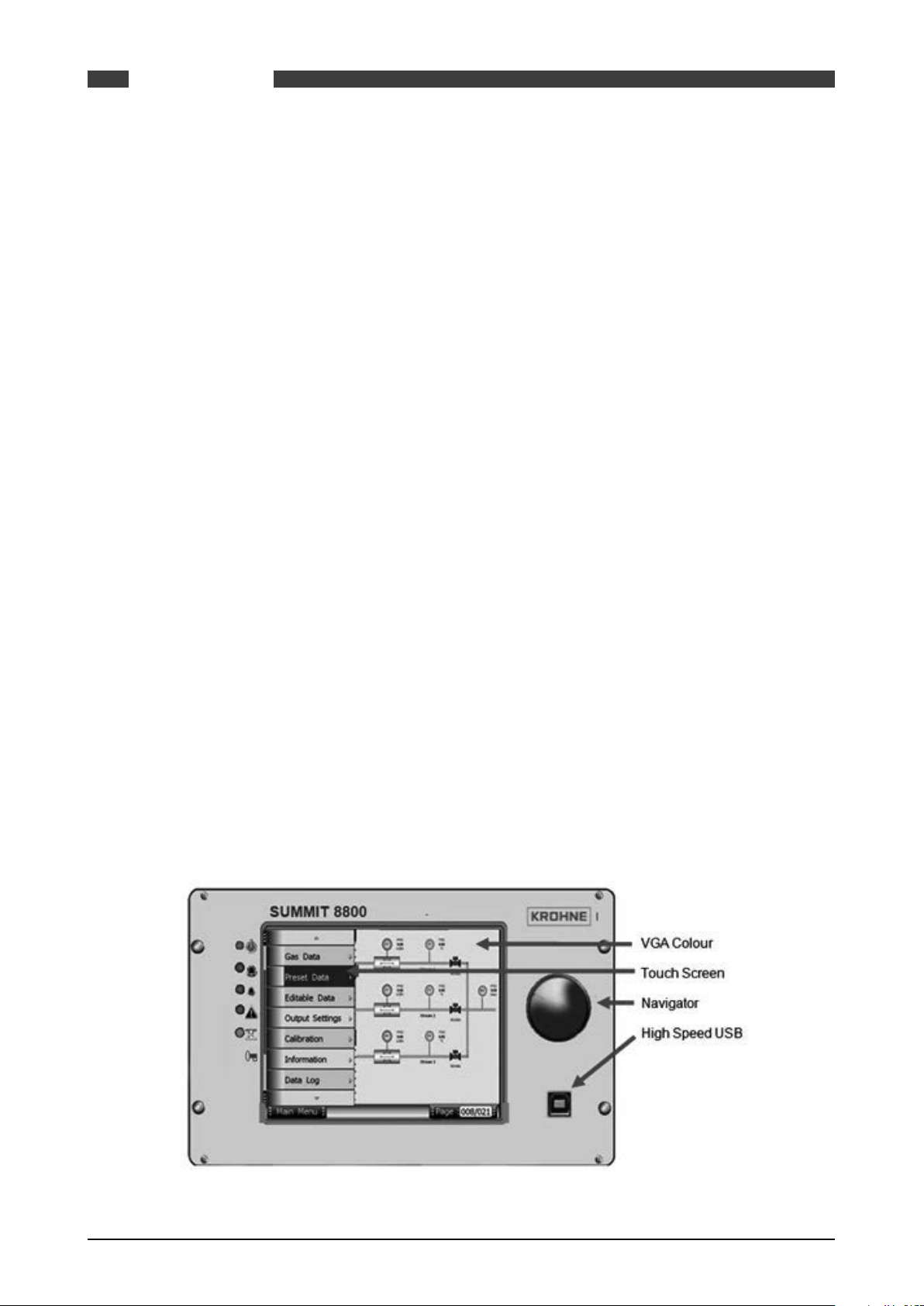
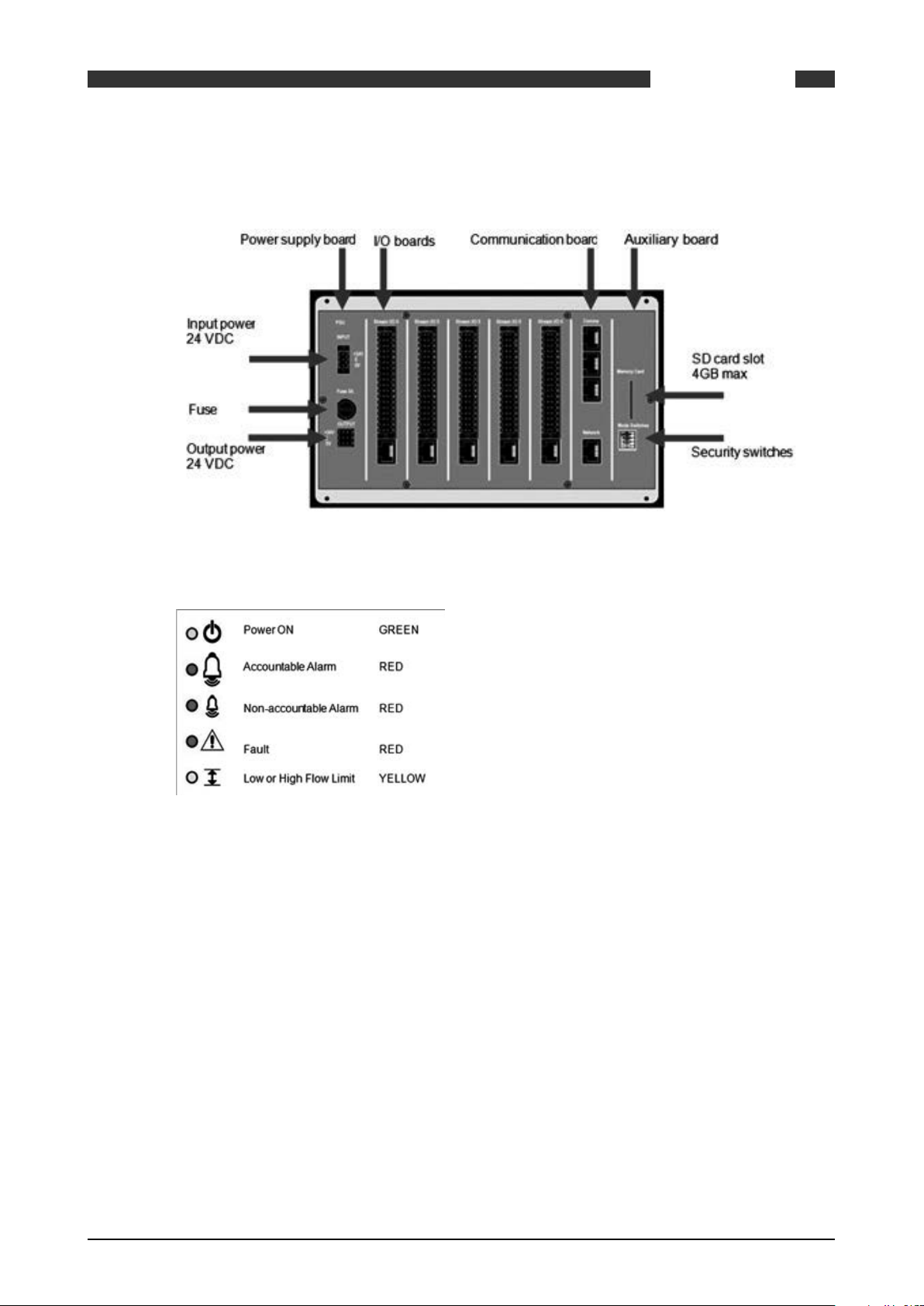
3.1.3 SUMMIT 8800 front panel layout
Figure 1 Front view of Summit 8800
18 www.krohne.com 08/2013 - MA SUMMIT 8800 Vol1 R02 en
Page 19
SUMMIT 8800
3.1.4 Rear Panel Layout
DESCRIPTION
03
Figure 2 Rear view of SUMMIT 8800
3.1.5 Alarms & LED’s
Figure 3 LED indicators
Power ON
This indicates that the SUMMIT 8800 is receiving an input power and is operating.
Accountable Alarm
These are alarms that need direct action because they could have effect on the result of the
calculations.
Accountable alarms are red and can be defined via the Configurator under stream n.
These are user defined values set within variable parameters such as temperature, pressure,
density. Within each run, the user can configure the minimum and maximum value for the
variable operating range. This alarm typically indicates that the full operating range has been
reached.
Non-accountable Alarm
These are user defined values set within variable parameters such as temperature, pressure,
density. Within each run, the user can configure the high and low value for the variable operating range which typically is always less than the maximum and minimum values entered. This
alarm typically indicates that the desirable operating range is being exceeded.
08/2013 - MA SUMMIT 8800 Vol1 R02 en
www.krohne.com
19
Page 20

SUMMIT 8800DESCRIPTION03
NOTE: These values (Max, Min, Hi and Lo) can be placed into a security display, where they can
be accessed by the “Edit” mode on the SUMMIT 8800.
Fault
Operational self-checking status.
In normal operation the self-checking routine, tests all memory components for data corruption. The watchdog circuit is also provided to detect a failure on the processor.
Faults will also be indicated for each board slot that contains a board that is either faulty, missing a critical board or the wrong type of board.
In case of a fault the LED will illuminate and all calculations will stop – an indication that a hardware error has been detected, that has affected the operation of the flow computer.
Flow Limits
An alarm that indicates that the user-defined low and high flow limits have been reached. These
limits are expressed as a percentage of the maximum and minimum flow rate, and are typically
lower than the maximum and minimum values.
Flow alarm will come on when the uncorrected flow is above the HiQ value (% of the max flow
rate) or below LoQ (% of the maximum flow rate).
When an alarm occurs, the yellow LED will illuminate.
The HiQ is an accountable alarm and the LoQ is a non-accountable alarm.
Further details on how to set these parameters are explained in Volume 2.
3.1.6 Description of Hardware memory devices
The SUMMIT 8800 contains the following types of hardware memory storage devices which are
integrated on the board and cannot be removed from the unit.
Flash Memory
• Used to store the operating program (legally relevant software) of the device
• Non-volatile memory requires no power source to maintain integrity of data.
• Can only be externally accessed (Read or Write) when the unit is in the boot mode for programming. This mode can only be accessed when a hardware switch seal is broken and
removed.
• Requires unique software tool to download and upload the program file via the USB port.
• Cannot be accessed using any common software tools.
• Integrity of program is maintained by the use of a CRC32 checksum.
Data Flash Memory (Configuration Data)
• Used to store all configuration and set-up parameters (legally relevant parameters).
• Non-volatile memory requires no power source to maintain integrity of data.
• Can only be externally written to when in open security mode. This mode can only be entered
when a hardware switch seal is broken and removed.
• Requires unique software tool to download and write the program file via the USB or ethernet
port
• Cannot be accessed using any common software tools.
• Integrity of data is maintained by the use of a CRC32 checksum.
Data Flash Memory (Recorded Data)
• Used to store all data log parameters
• Used to store all audit trail data and parameters
20 www.krohne.com 08/2013 - MA SUMMIT 8800 Vol1 R02 en
Page 21

SUMMIT 8800
• Used to store all alarm record data and parameters
• Non-volatile memory requires no power source to maintain integrity of data.
• Cannot be written to from any external source: it is read only memory.
• Requires unique software tool to upload the data files via the USB or ethernet port
• Cannot be accessed using any common software tools.
• Integrity of each individual data, audit or alarm record is maintained by the use of a recorded
time stamp and an individual CRC32 checksum for each individual record.
Static RAM Memory (Recorded Data)
• Used to store calculation results. Data that can change on every calculation cycle, e.g. flow
measurement totals and parameter averages.
• Non-volatile memory that requires internal lithium back-up battery to maintain integrity of
data.
• Backup battery is integrated inside the unit and cannot be switched off or removed without
breaking a hardware seal and removing the rear panel of the unit.
• Backup battery capacity is sufficient to maintain data for at least 5 years of normal operation.
• Backup battery condition is continuously monitored and indication is given when replacement
is due.
• Cannot be written to from any external source: it is read only memory.
• Requires a unique software tool to upload the data files via the USB port or ethernet port
• Cannot be accessed using any common software tools.
• Integrity of the data is maintained by the use of duplicate records for each value which are
verified against individual CRC32 checksums for each individual record block.
DESCRIPTION
03
The SUMMIT 8800 also contains the following types of optional hardware memory storage devices which are integrated in the design of the SUMMIT 8800 but can be removed from the unit.
SD memory Card
• Used to store data log parameters (separate from data logs stored in data flash memory)
• Up to 4GB of data storage or typically lifetime storage.
• Used to store all audit trail data and parameters (duplicate copy of audit trail data stored in
data flash memory)
• Non-volatile memory requires no power source to maintain integrity of data.
• Cannot be written to from any external source: it has an internal coding.
• Requires a unique software tool to upload the data files via the USB or ethernet port or via a
SD slot in a PC
• Cannot be accessed using any common software tools.
• Integrity of each individual data, audit or alarm record is maintained by the use of a recorded
time stamp and an individual CRC32 checksum for each individual record.
• Can be removed from the unit at any time.
3.2 Features SUMMIT 8800
3.2.1 Key Features
• Touch screen
• VGA colour graphics & Navigator dial.
• Multi-processing makes the unit 10-50x faster than traditional flow computers
• 50-2000 times more memory
• Years of data storage
• More accuracy due to more frequent calculations
• Modular design hard- and software, Pay only for what is needed
• Up to 6+ runs, Affordable for allocation metering
• Supervisory like functions, More capabilities for lower price
• Audit trail up to person
• Network capabilities, Metering info available centrally
08/2013 - MA SUMMIT 8800 Vol1 R02 en
www.krohne.com
21
Page 22

• Pulse handling: API5.5 level A, B, C, D, E, Dual chronometry, pulse interpolation
• Calibration up to 20 points linear, meter factor or K-curve, 5 products (future at present 1)
• Density/ specific gravity: frequencies Solartron 781x, 783x, Sarasota ID900
• Counters: Unhaltable, Normal, Period, Error, Maintenance, Positive and negative, Prover
• Averages: Time weighted, Flow weighted.
• Provers: Bi-directional, 2 / 4 detector inputs, piston prover, master provers
• Control: up to 18 valves, Prover, PID
• TCP/IP and serial Modbus protocols for
Ultrasonic meters: KROHNE AIII, AV, V12, Daniel, Elster, GE, Sick
Chromatographs: ABB, Daniel, Elster, Siemens
• And custom configurable protocols.
3.2.2 Calculations & Compliance standards
AGA3 (Orifice meters) gas flow calculations.
AGA5 (Natural Gas Energy Measurement)
AGA7 (Measurement of Natural Gas by Turbine Meter)
AGA8 (Compressibility Factor of Natural Gas and Related Hydrocarbon Gases)
AGA9-support (Measurement of Gas by Multipath Ultrasonic Meters)
AGA10 (Speed of Sound in Natural Gas and Other Related Hydrocarbon Gases)
API MPMS (Manual of
Petroleum Measurement
Standards):
API 2540
ASTM D1250 IP200
GPA 2172, TP-27
GOST NX19
ISO 5167 (2003 , 1997, 1991)
ISO 6976
NX19, NX19 G9
OIML R117-1 Edition 2007
PTZ, NX19, NX19 G9, SGERG (all types), User-defined Z-factor Tables, fixed
SGERG (all types)
WELMEC guide 8.8
Chapter 5.6 (Measurement of Liquid Hydrocarbons by Coriolis Meters)
Chapters 11.1, 11.2, 21.1 & 21.2 etc
Chapters 12.2.5.1 & 2
Chapter 12.2.5.3 Table 54, 54A, 54B, 54D
SUMMIT 8800DESCRIPTION03
... and more to come
3.3 Integration possibilities
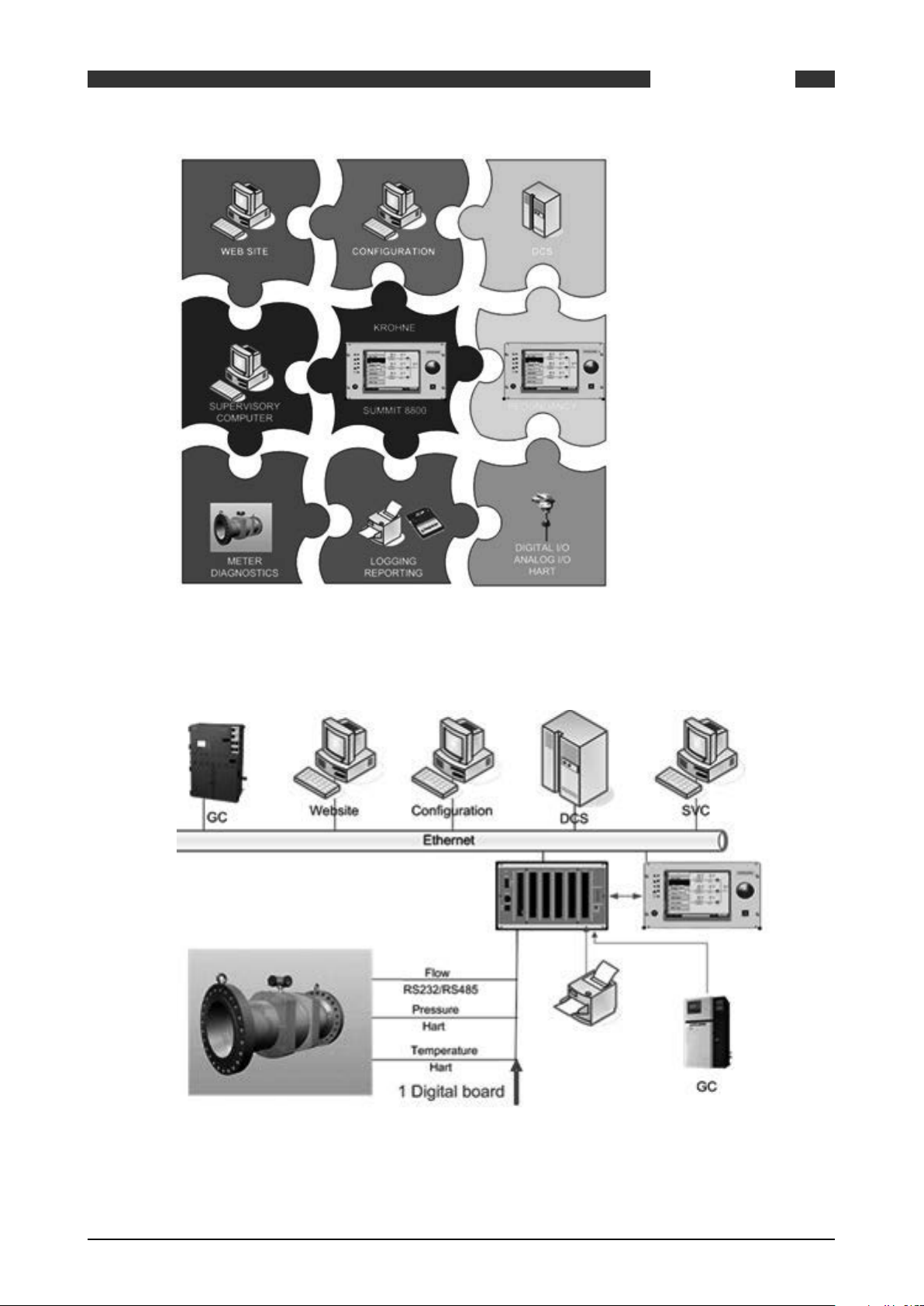
3.3.1 System Integration
The SUMMIT 8800 can be integrated as a component within a fully automated system.
When within a system, the SUMMIT 8800 is usually an intermediate device interacting with all
field devices and supervisory systems.
22 www.krohne.com 08/2013 - MA SUMMIT 8800 Vol1 R02 en
Page 23
SUMMIT 8800
DESCRIPTION
03
Figure 4 SUMMIT 8800 system integration overview
3.3.2 Application integration
Figure 5 Stream application integration
08/2013 - MA SUMMIT 8800 Vol1 R02 en
www.krohne.com
23
Page 24
4. Installation and Replacement
Please read these instructions carefully before assembling or installing this product to avoid
danger to people, pets and damage to connecting devices and the SUMMIT 8800. Installation of
this product may only be performed by qualified personnel.
The SUMMIT 8800 comes with all links and internal switches set to factory default see Chapter
Hardware Details: Rear panel Mode Switches.
Before any power or signal connections are applied to the SUMMIT 8800 the qualified personnel
should ensure that all links are set at the correct position for the appropriate and intended use.
Failure to do so may result in damage to the SUMMIT 8800 and any associated equipment.
The flow computer device is powered with +24VDC.
Do not touch any of the internal components whilst the unit is powered.
Turn off the power to the SUMMIT 8800 before opening the device or installing the product.
Only energize the device when it is wired, installed and all covers are securely in place.
SUMMIT 8800INSTALLATION AND REPLACEMENT04
4.1 Mechanical Specifications
4.1.1 Mechanical Installation
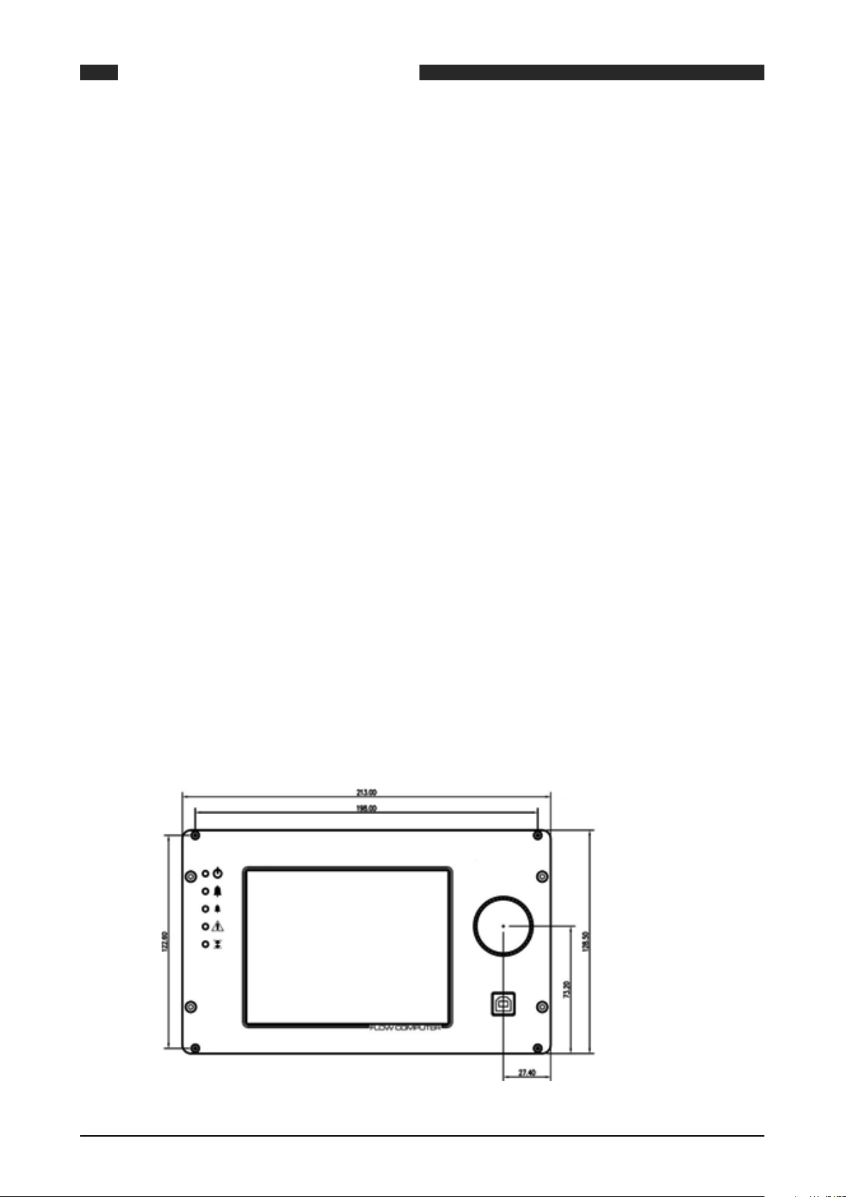
All installation tasks should be performed by qualified personnel. The external chassis dimensions (for panel or rack mounting) are given in the figure below. Ensure that the ventilation
slots on the upper and lower surfaces on the SUMMIT 8800 are kept clear from any obstruction.
Ensure that ventilation and shading is provided when the SUMMIT 8800 is subjected to high
ambient temperatures (such as being near heat producing apparatus) or to direct sunlight. The
operating environment must be clean, dry and free from corrosive elements.
NOTE: When used as part of MID approval which states the use of the SUMMIT 8800 to be
indoors and in a controlled environment where it is subject to the requirements of EN 12405,
the SUMMIT 8800 must be mounted in an enclosure with an ingress protection rating of IP65 or
better.
Front
24 www.krohne.com 08/2013 - MA SUMMIT 8800 Vol1 R02 en
Page 25
SUMMIT 8800 INSTALLATION AND REPLACEMENT
Side
Panel cut-out
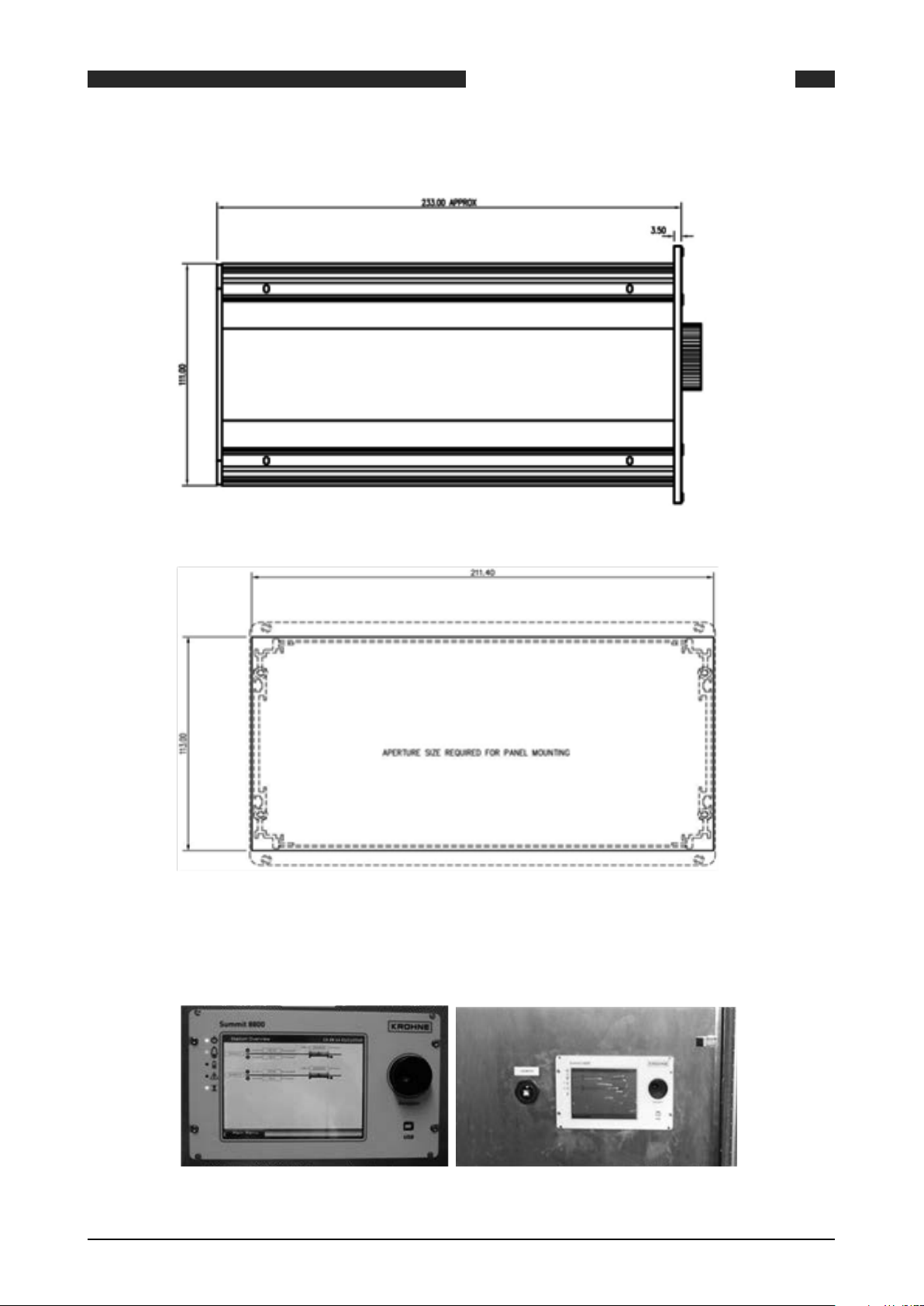
04
Figure 6 Dimensions & Outlines
4.1.2 Panel Mounting
Figure 7 Panel mounted installations
08/2013 - MA SUMMIT 8800 Vol1 R02 en
www.krohne.com
25
Page 26
The SUMMIT 8800 can be mounted in a panel. For this, use the dimensions for the panel cut-out
as described in the previous paragraph. Please note that the SUMMIT 8800 is fixed to the panel
using the bolts on top and bottom of the SUMMIT 8800.
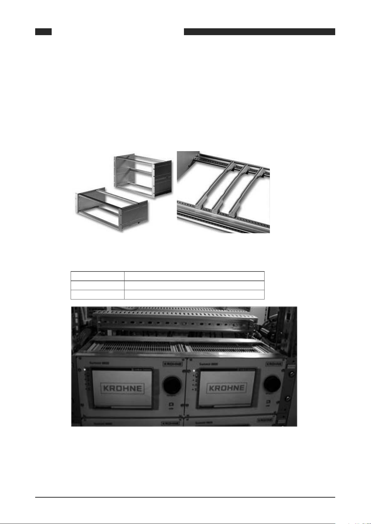
4.1.3 Rack mounting options
For the SUMMIT 8800 optional rack mounting kits are available to ease cabinet, rack or panel
installation. Please consult your local KROHNE sales department or major suppliers such as
Farnell and Rittal.
SUMMIT 8800INSTALLATION AND REPLACEMENT04
Figure 8 Rack mounting kit
Ordering code:
Rittal RP 3688115 Subrack RIPAC ECO 3Ux235
Farnell 3688115 - SUBRACK, ECO, 3U, 235MM, 84HP 1198862
RS components PCB guide kit, 500-566 (4*)
Figure 9 Rack mounted installation
4.1.4 Cable Assembly
For rack mounted installations, a 2.5m rail mounted terminal cable loom assembly is available
for the SUMMIT 8800 flow computer.
26 www.krohne.com 08/2013 - MA SUMMIT 8800 Vol1 R02 en
Page 27

SUMMIT 8800 INSTALLATION AND REPLACEMENT
Figure 10 Cable assembly
4.2 Electrical Specifications
4.2.1 Electrical Installation
04
The SUMMIT 8800 is certified to be in compliance with IEC 61010-1:2001 provided it is installed
in accordance with the instructions supplied.
The SUMMIT 8800 must be powered by:
A Class 2 power supply is defined by article 725.41 of the National Electrical Code (NEC Code
book) and has limited output power.
In addition the wiring between the SUMMIT 8800 and its power supply must be sufficiently rated
(10A) with a minimum cross section area of 1.5mm2 and PVC insulation. A suitable rated switch
or circuit breaker must be included to allow isolation of power supply to the SUMMIT 8800. The
device should be mounted as near to the equipment as practically possible.
No routine maintenance is required to ensure continuous operation; however, should a system
failure occur during operations, then the most likely cause of malfunction is that of a requirement not being fully or correctly implemented. If a fault or warning occurs, the cause should be
determined in a logical and systematic manner following the guide given below. All maintenance
tasks should be carried out by qualified personnel only.
08/2013 - MA SUMMIT 8800 Vol1 R02 en
www.krohne.com
27
Page 28
SUMMIT 8800INSTALLATION AND REPLACEMENT04
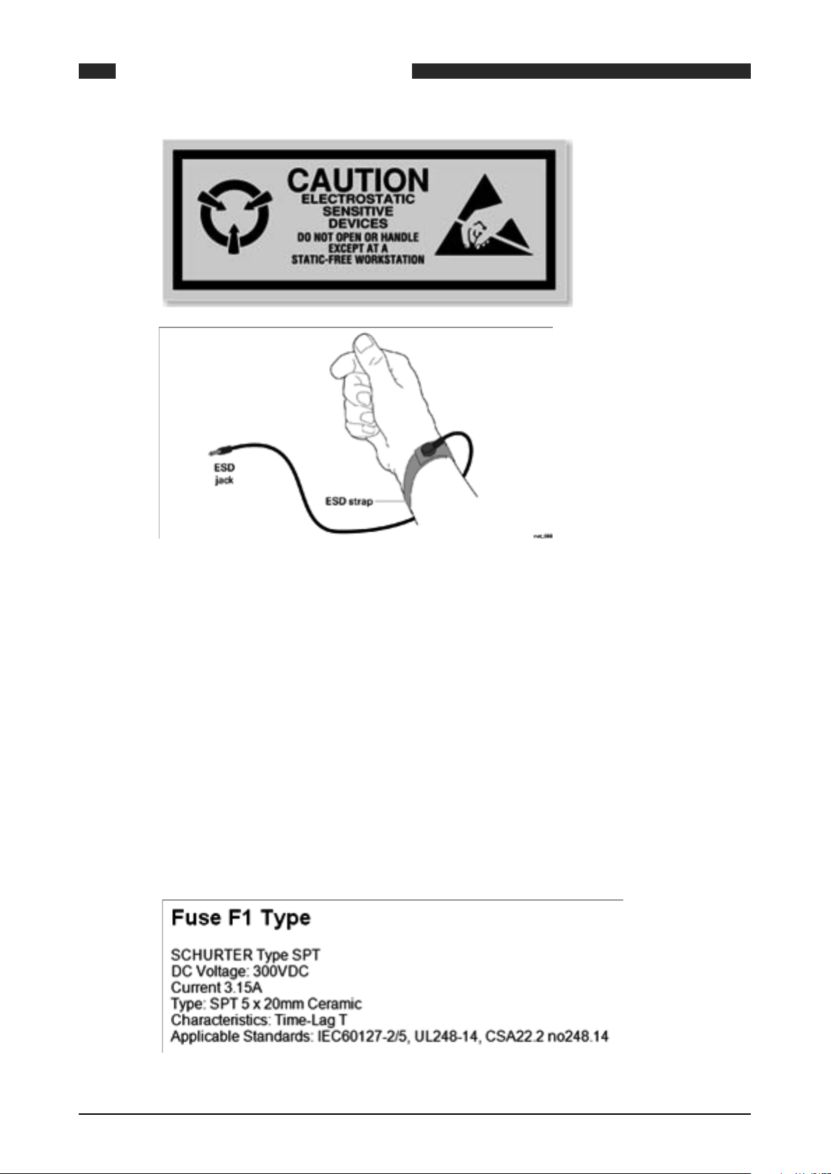
Some parts of the instrument such as circuit boards may be damaged by static electricity. When
handling internal parts of the instruments, ensure that anti-static precautions are taken. It is
therefore essential when carrying out any maintenance or installation work that an earthed
wrist strap be worn, or other such precautions, whenever internal parts of the instrument are
handled.
4.2.2 Earthing Requirements
The SUMMIT 8800 must be connected to a suitable ground or earth connection via the M4 earth
stud located at the rear of the chassis. See below for details.
4.2.3 Fuses and Battery
The SUMMIT 8800 has an internal fuse F1 and an externally accessible fuse F2 on the rear
panel. Fuse F1 protects the DC input circuits and can only be replaced by qualified personnel.
Isolate the main power to the SUMMIT 8800. Remove the rear panel as specified under Hardware Details. Withdraw the PSU board and identify F1 as detailed in the figure below. Replace
fuse F1 only with a replacement fuse type:
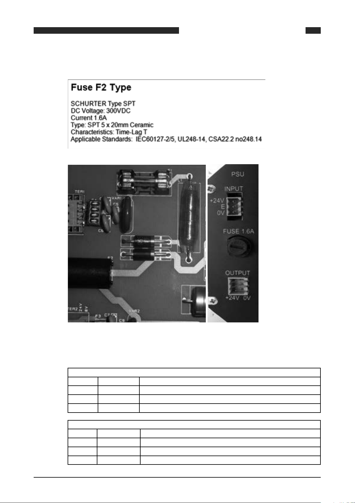
Fuse F2 protects the DC output and can be replaced by all personnel. Isolate the main power
28 www.krohne.com 08/2013 - MA SUMMIT 8800 Vol1 R02 en
Page 29
SUMMIT 8800 INSTALLATION AND REPLACEMENT
to the Flow Computer SUMMIT 8800. Rotate the cap of fuse holder F2 counter clockwise and
replace fuse F2 only with a replacement fuse type:
04
Figure 11 Fuse F1 (left) en F2 (right)
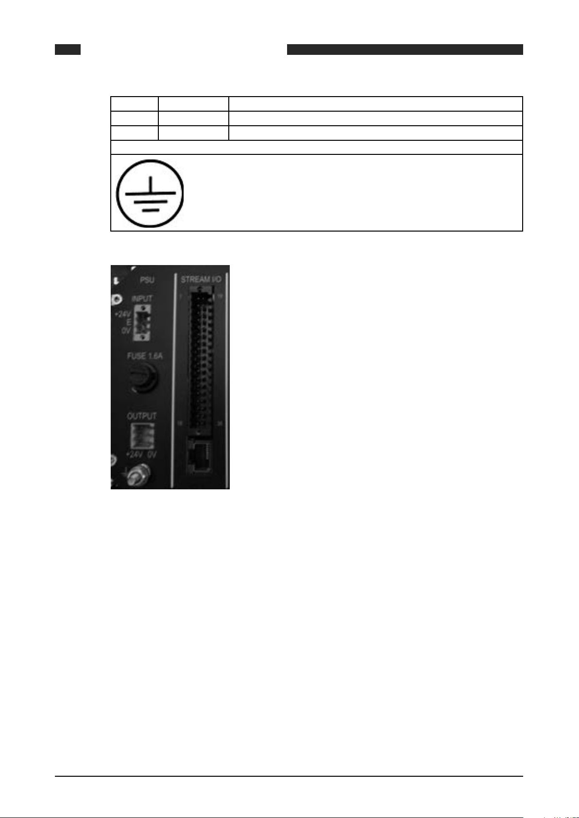
4.2.4 Power Supply Terminals
POWER SUPPLY INPUT CONNECTOR TER 1
Terminal FUNCTION
1 +24V DC +24V DC positive power supply Terminal
2 E Earth connection terminal
3 0V Power Supply 0V terminal
AUXILIARY POWER SUPPLY OUTPUT CONNECTOR TER 2
Terminal FUNCTION
1 +24V DC +24V DC Auxiliary output supply
2 +24V DC +24V DC Auxiliary output supply
3 +24V DC +24V DC Auxiliary output supply I max = 200mA
08/2013 - MA SUMMIT 8800 Vol1 R02 en
www.krohne.com
29
Page 30
4 0V 0V Auxiliary output supply
5 0V 0V Auxiliary output supply
6 0V 0V Auxiliary output supply
CHASSIS EARTH SCREW TERMINAL
Earth stud terminal M4
SUMMIT 8800INSTALLATION AND REPLACEMENT04
Figure 12 Power & M4 earth connections
4.2.5 Back Up Battery
The SUMMIT 8800 contains a backup battery on the auxiliary card, this battery keeps the real
time clock and internal totals when DC power to the unit is disconnected. Replacement of this
battery should only be carried out by qualified personnel.
If the SUMMIT 8800 is kept continuously powered, the back-up battery estimated life is 10 years.
If the SUMMIT 8800 is powered down for periods exceeding 30 days, the battery should be removed and stored separately. The battery needs to be replaced when its service life exceeds 10
years or when it has been left in an un-powered unit for a time period of greater than 2 months.
A “BAD” battery condition is indicated via the Windows software.
When a “BAD” battery condition is indicated via the Windows software or on the front panel:
30 www.krohne.com 08/2013 - MA SUMMIT 8800 Vol1 R02 en
Page 31

SUMMIT 8800 INSTALLATION AND REPLACEMENT
Figure 13 Configurator good and bad battery indicator
Illustration of bad battery as shown on the front panel of the SUMMIT 8800:
Figure 14 Bad battery indicator on front panel
04
NOTE: When the battery is missing or requires replacement the flashing battery symbol as
above shown adjacent to the Time and Date on all display screens. When the Battery is within
operating parameters no symbol is shown.
4.2.5.1 Copy and Restore Main Totals
After switching off the power, the totals will be lost and cannot be recalled from memory anymore.
Therefore the user must first take note of all totalizer values before switching off the power to
the SUMMIT 8800 and replace a backup battery
The totals can be read but cannot be preset or changed via the front screen, this can only be
done by using the Configurator.
• So before replacing the battery, make a copy of all totals.
• After replacing the battery, load the application into the Configurator software (see load setup
in Chapter Configuration Software: Working with Configuration Setups). Under stream/Totals,
populate the preset totals with the last total and download the application to the SUMMIT
8800.
The totalizers should only be restored when replacing the backup battery or in extreme cases.
08/2013 - MA SUMMIT 8800 Vol1 R02 en
www.krohne.com
31
Page 32

Figure 15 Totalizers enter field
4.2.5.2 Back Up Battery Replacement
SUMMIT 8800INSTALLATION AND REPLACEMENT04
To replace or install the backup battery please follow the instructions detailed.
• Record main totals as these will be lost during power down.
• Disconnect all cables from the rear of the SUMMIT 8800 and remove the rear panel as shown
under Hardware Details.
• Withdraw the auxiliary card from the chassis and then remove the battery as previously
shown.
• Replace the battery only with a new replacement type as detailed below:
Figure 16 Auxiliary board
32 www.krohne.com 08/2013 - MA SUMMIT 8800 Vol1 R02 en
Page 33

SUMMIT 8800 INSTALLATION AND REPLACEMENT
NOTE: Under CSA the correct battery type must be used.
4.2.6 Real time clock
The real time clock is powered by the backup battery. If the battery is replaced, make sure that
the time is set correctly afterwards.
04
The date and time can be set within “edit” mode on the SUMMIT 8800, if the “time” parameter
has been made available in the display by the integrator.
The same can be done from the Configurator within the general tab under date/time. See volume 2.
The accuracy of the clock is optimized for 20°C and deviates +/- 3 ppm/°C, (it is recommended
that the ambient temperature around the flow computer is maintained as close as possible to
20°C), it is therefore a good habit to synchronise the clocks.
The most effective way to synchronise the clock is by the network using a time server and SNTP.
It is also possible to synchronise via a supervisory system using Modbus.
Care should be taken using summer- and wintertime. Change-over will result in longer or
shorter days and associated different daily totals.
08/2013 - MA SUMMIT 8800 Vol1 R02 en
www.krohne.com
33
Page 34

5. Hardware Details
5.1 Front Panel
The front panel of the SUMMIT 8800 is a clean and simple design utilising a 5.7” VGA touch
screen, an optical rotary dial for navigation, five LED’s and front USB port for ease of communication.
Clean the Front Panel Touch Screen with water moist cloth only.
SUMMIT 8800HARDWARE DETAILS05
Figure 17 Front panel of SUMMIT 8800 & USB port
5.1.1 Associated software
The programming port on the front panel is a standard USB type B version. The programming
port is used for the transfer of configuration and setup data and for downloading of results,
tables and report data. See Chapter: Configuration Software.
When new firmware (operating software) is required for the unit or one of the boards, updates
can be performed via the USB port and using the firmware wizard software. More information on
this software can be found in Chapter: Firmware.
When people are trained in a class room environment on the use of a SUMMIT 8800 flow computer, the flow computer screen data can be forwarded to a laptop and can then be projected on
a large screen via the USB SUMMIT 8800 display monitor software. See Chapter: Display Monitor.
If an optional dual Ethernet is available, a web site can be used that mimics the SUMMIT 8800
display but also enables to get alarm, audit log and parameter data. See Chapter: Web Access.
5.2 Rear Panel
5.2.1 Removal of the Rear Panel
• Remove all cables and plug in connectors from the sockets on the rear of the SUMMIT 8800.
• Remove the 4 cross screws at each corner.
• Carefully pull the rear panel away from the chassis.
34 www.krohne.com 08/2013 - MA SUMMIT 8800 Vol1 R02 en
Page 35

SUMMIT 8800 HARDWARE DETAILS
• Re-fitting is the reverse of this procedure.
When refitting, care should be taken to ensure that all terminals, switches and connectors protrude through the rear panel and are not trapped behind it before tightening the fixing screws.
05
Figure 18 Rear panel of SUMMIT 8800 and removal screws
5.2.2 Rear panel Mode Switches
On the rear panel there are 4 Mode or Function switches located on the Auxiliary board. These
switches determine the basic operating mode of the SUMMIT 8800.
The designation and function of the mode switches is as follows:
Switch ON OFF
1 Run Mode Boot Mode
2 No function -
3 Security 2 On Security 2 Off
4 Security 3 On Security 3 Off
Switch 3 Switch 4 Security mode
OFF OFF Open
OFF ON Partial
ON OFF Partial
ON ON Full
Figure 19 Mode Switch settings
The switches control the operation mode of the SUMMIT 8800:
Run mode Used for normal operation of the computer
Boot mode Boot Mode should only be used for uploading new firmware Versions in conjunction
with the supplied Windows operating software
They also control the security level of the SUMMIT 8800:
08/2013 - MA SUMMIT 8800 Vol1 R02 en
www.krohne.com
35
Page 36

SUMMIT 8800HARDWARE DETAILS05
OPEN The SUMMIT 8800 is fully open and changes can be made without restrictions.
However, user passwords are required.
PARTIAL In this mode the front panel Edit mode can be accessed with the proper user pass-
word, but calibration data cannot be changed.
New application information cannot be uploaded or downloaded. The existing configuration can be downloaded, changed and uploaded again. The type of changes allowed
can be defined using the configurator Software and will typically be non-critical configuration data, parameters and values.
FULL Connection is possible and applications can be uploaded, but cannot be downloaded
to and from the SUMMIT 8800 as it is in Read only mode. Change in parameters, values or any other data is not possible. Configuration data cannot be changed with the
GUI software. Edit menu cannot be accessed. Calibration data cannot be changed.
Alarms and audit data cannot be cleared.
It is possible to define in the configuration in which mode alarms can be acknowledged or
cleared and audit data can be cleared.
The settings of the Security mode, can be found on the System information page:
Figure 20 System information screen
5.2.3 SD Card
The SUMMIT 8800 contains a replaceable SD memory card on the Auxiliary board, this card can
be used to store Audit and Data Log Information. It can be replaced at any time by withdrawing from the connector on the rear panel and a new card can be inserted. When a new card is
inserted it is automatically detected. Depending upon its formatting and use, possible messages
and instructions will appear on the main screen.
Follow the on-screen instructions, and the card should be prepared ready for use.
Once removed, a filled or partially filled card can have its data read using a standard PC card
reader and the supplied Windows software.
The SD can also be read whilst installed in the SUMMIT 8800 by using the configuration software.
36 www.krohne.com 08/2013 - MA SUMMIT 8800 Vol1 R02 en
Page 37

SUMMIT 8800 HARDWARE DETAILS
Maximum SD capacity is 4GB
Figure 21 Illustration of inserted SD card
5.3 Standard hardware components
The SUMMIT 8800 is a modular design flow computer made up of various hardware components
based on your input and output requirements. There are mandatory components which are required for the operation of the flow computer such as the CPU, PSU, auxiliary board and at least
one I/O and communication board which are positioned within a chassis.
05
Figure 22 Modular design chassis
The SUMMIT 8800 is a modular based flow computer, consisting of a main CPU, PSU, Auxiliary
board and 1 - 6 I/O and communication boards
When viewed from the rear, the CPU is positioned directly behind the front panel and sits between the front panel and mother board ports where the PSU, Auxiliary board, I/O and communication boards slot into.
08/2013 - MA SUMMIT 8800 Vol1 R02 en
www.krohne.com
37
Page 38

SUMMIT 8800HARDWARE DETAILS05
Figure 23 Board slots with mother board & rear view panel
The PSU board sits in the first port on the far left, and the Auxiliary board sits into the slot on the
far right.
All I/O boards including communication boards can be positioned in any slot, however good
engineering practice it is recommended that all I/O boards are positioned on the left and the
communication boards to the right.
5.3.1 CPU Board Description
The Central Processing Unit board is the computational process board and is the main processing component for the SUMMIT 8800.
5.3.2 PSU Board Description
The PSU board can only be exchanged by qualified personnel. Only one of these cards is required in a chassis and this card must be positioned in the first left hand chassis slot position.
The function of the PSU card is to provide the power supply requirements of the SUMMIT 8800.
Figure 24 Power supply unit
5.3.2.1 PSU Board Settings
Details of position of PSU Board Fuses
38 www.krohne.com 08/2013 - MA SUMMIT 8800 Vol1 R02 en
Page 39

SUMMIT 8800 HARDWARE DETAILS
Figure 25 PSU board components
05
Fuse Function Fuse Type
1 Unit main fuse See Chapter Installation and Replacement: Fuses and Batteries
2 External +24V fuse
(user equipment)
Table 1 Location of fuses on PSU
5.3.3 Auxiliary Board Description
The Auxiliary board can only be exchanged by qualified personnel. Only one of these cards is
required in a chassis and this card must be positioned in the last most right hand chassis slot
position. The function of the Auxiliary card is to provide the mounting for the backup battery,
mounting for an optional SD memory card and the rear panel mode dipswitches.
See Chapter Installation and Replacement: Fuses and Batteries
Figure 26 Auxiliary board
08/2013 - MA SUMMIT 8800 Vol1 R02 en
www.krohne.com
39
Page 40

5.3.3.1 Auxiliary Board Settings
SUMMIT 8800HARDWARE DETAILS05
Figure 27 Auxiliary board components
The figure above shows the position of the Auxiliary board user replaceable parts:
• Backup battery
• SD memory card optional
5.4 Optional Plug-in boards
There are seven different types of optional boards available for the SUMMIT 8800, four of which
are I/O boards. Our sales team can advise and select the appropriate board for your application. There are several factors that are taken into consideration when selecting the correct I/O
board(s) such as the number of field instruments, type of signals used, and output required
including communication. Each I/O board is featured with a single serial communication port.
Figure 28 Typical I/O board
5.4.1 Board Selection
The I/O board selected is determined by the number of inputs and outputs required for the
number of Runs being configured. The table below illustrates the type and number of inputs and
outputs for each I/O board.
40 www.krohne.com 08/2013 - MA SUMMIT 8800 Vol1 R02 en
Page 41

SUMMIT 8800 HARDWARE DETAILS
05
I/O Analog
Input
Board
Analog *4 5 1 3 *5 1 2 1 - -
Digital 1 - 5 2 2 5 1 - 1 - -
Digital 2 - 4 2 4 6 - - 1 - -
Switch - 12 - - 12 - *6 1 - -
Single
comms
Dual
Comms
DSfG** 4 1
Table 2 Boards with available Inputs & Outputs
- - - - - - - 3 - 1
- - - - - - - 3 - 2
*Selectable explanation
Analog: 2x digital outputs or 2 analog inputs
Switch: 6x digital inputs or 6 digital outputs
** Please note that the DSfG board is dedicated to the German DSfG protocol only.
5.4.2 Terminal Connectors
Digital
Input
HART
Input
Analog
Output
Digital
Output
PRT Select-
able*
Serial USB Ethernet
The input transmitter circuits are connected to the SUMMIT 8800 via the 36-pole terminal connections on the rear panel of the flow computer. Before any of transmitters are connected, refer
to the instrument instruction manual applicable to the individual transmitter.
Connection methods are simply a basic indication of how the devices can be connected together.
Warning:
In hazardous environments a transmitter must be connected in accordance with the safety certificate conditions specified for the individual transmitter.
Tension clamps are used in the SUMMIT 8800. This means that the wires can be inserted without
the need of a screw driver.
Figure 29 Illustration method of cable insertion into clamp
08/2013 - MA SUMMIT 8800 Vol1 R02 en
www.krohne.com
41
Page 42

5.4.3 Serial Communication Connection
A serial port is available on all I/O boards and terminal connections are universal for digitals,
analogue and switch I/O boards.
Figure 30 Serial port I/O boards rear terminal pin allocation
5.5 Digital I/O Board
SUMMIT 8800HARDWARE DETAILS05
The digital I/O board 1 can only be exchanged by qualified personnel. Up to a maximum of 6
cards can be inserted in any of the plug in slots in the SUMMIT 8800 chassis. A board can provide
input and output functions as detailed:
• 3 pulse counting/frequency measuring inputs (for use with turbine meters, rotary meters,
density or relative density transducers).
• 2 digital status inputs for use with switch or contact inputs.
• 2 Smart transmitter (HART) loops. Each loop can provide connections for up to 3 transmitters
each with four variables such as pressure, temperature or differential pressure transmitters.
• 1 Direct 4 wire RTD input for direct measurement of temperature.
• 5 digital transistor switched outputs for use in telemetry systems or for alarm indication.
• 2 analog 4-20 mA outputs for use in telemetry or control systems.
• 1 Serial communication port using either (RS232 or half duplex RS485), providing connection
to gas meters, gas chromatographs or other equipment that transfers data via serial communication.
42 www.krohne.com 08/2013 - MA SUMMIT 8800 Vol1 R02 en
Page 43

SUMMIT 8800 HARDWARE DETAILS
5.5.1 Digital I/O Board 1 terminal connections
05
Figure 31 Digital I/O board 1 rear terminal pin allocation
5.5.1.1 Serial communication connection
For the serial communication connection, refer to appropriate section given in Contents.
5.5.2 Digital I/O Board 1 Settings
The following sections contain details of the user controls and settings for the digital I/O 1
board.
5.5.2.1 Digital Input Settings
Position of digital input links shown on top edge of digital I/O boards
08/2013 - MA SUMMIT 8800 Vol1 R02 en
www.krohne.com
43
Page 44

Figure 32 Digital I/O board digital input link setting
Table 3 Digital I/O board 1 link settings
SUMMIT 8800HARDWARE DETAILS05
Link Function Factory
setting
8 Digital input 1 resistor bypass OFF
9 Digital input 1 0V24 connection OFF
10 Digital input 2 resistor bypass OFF
11 Digital input 2 0V24 connection OFF
12 Digital input 3 resistor bypass OFF
13 Digital input 3 0V24 connection OFF
14 Digital input 4 resistor bypass OFF
15 Digital input 4 0V24 connection OFF
16 Digital input 5 resistor bypass OFF
17 Digital input 5 0V24 connection OFF
5.5.2.2 HART Loop Settings
Position of HART loop links shown on left hand edge of digital I/O board
Figure 33 Digital I/O board HART loop link settings
Table 4 HART loop settings on digital I/O board 1
5.5.2.3 RS485 Settings
Position of RS485 termination network links shown on left hand edge of digital I/O board
Link Function Factory
setting
6 HART loop 1 0V24 connection ON
7 HART loop 2 0V24 connection ON
Link Function Factory
setting
4 RS485 termination network con-
nection
5 RS485 termination network con-
nection
OFF
OFF
Figure 34 Digital I/O board RS485 termination link setting
Table 5 Serial settings on digital I/O board 1
44 www.krohne.com 08/2013 - MA SUMMIT 8800 Vol1 R02 en
Page 45

SUMMIT 8800 HARDWARE DETAILS
5.6 Digital I/O Board 2
The digital I/O board 2 can only be exchanged by qualified personnel. Up to a maximum of 6
cards can be inserted in any of the 6 plug in slots in the SUMMIT 8800 chassis. A board can provide input and output functions as detailed:
• 3 pulse counting/frequency measuring inputs (for use with turbine meters, rotary meters,
density or relative density transducers).
• 1 Digital status inputs for use with switch or contact inputs.
• 2 Smart transmitter (HART) loops. Each loop can provide connections for up to 3 transmitters
each with four variables such as pressure, temperature or differential pressure transmitters.
• 6 digital transistor switched outputs for use in telemetry systems or for alarm indication.
• 4 analog 4-20 mA outputs for use in telemetry or control systems.
• 1 Serial communication port using either (RS232 or half duplex RS485), providing connection
to gas meters, gas chromatographs or other equipment that transfers data via serial communication.
NOTE: Only configure pulse output 1 for Prover corrected bus.
05
An individual stream (or run) can be monitored by one digital I/O board as it provides all the necessary inputs and outputs. Note that individual inputs and outputs can be configured separately
and are not limited to a specific measurement run.
5.6.1 Digital /O Board 2 Terminal Connections
Figure 35 Digital I/O board 2 rear terminal pin allocation
08/2013 - MA SUMMIT 8800 Vol1 R02 en
www.krohne.com
45
Page 46

5.6.1.1 Serial communication connection
For the serial communication connection, refer to the appropriate section given in Contents.
5.6.2 Digital I/O Board 2 Settings
The following sections contain details of the user controls and settings for the digital I/O 2
board.
5.6.2.1 Digital Input Settings
Position of digital input links shown on top edge of digital I/O board2
SUMMIT 8800HARDWARE DETAILS05
Link Function Factory
setting
8 Digital Input 1 resistor bypass OFF
9 Digital Input 1 0V24 connection OFF
10 Digital Input 2 resistor bypass OFF
11 Digital Input 2 0V24 connection OFF
12 Digital Input 3 resistor bypass OFF
13 Digital Input 3 0V24 connection OFF
14 Digital Input 4 resistor bypass OFF
15 Digital Input 4 0V24 connection OFF
Figure 36 Digital I/O board digital input link setting
Table 6 Digital I/O board 2 settings
5.6.2.2 HART Loop Settings
Position of HART loop links shown on left hand edge of digital I/O board 2
Figure 37 Digital I/O board 2 HART loop link settings
Table 7 HART loop settings on digital I/O board 2
Link Function Factory
setting
6 HART loop 1 0V24 connection ON
7 HART loop 2 0V24 connection ON
5.6.2.3 RS485 Settings
Position of RS485 termination network links shown on left hand edge of digital I/O board 2
46 www.krohne.com 08/2013 - MA SUMMIT 8800 Vol1 R02 en
Page 47

SUMMIT 8800 HARDWARE DETAILS
Link Function Factory
4 RS485 termination network connection OFF
5 RS485 termination network connection OFF
Figure 38 Digital I/O board 2 RS485 termination link setting
Table 8 Serial settings on digital I/O board 2
5.7 Analog I/O Board
The analog I/O board can only be exchanged by qualified personnel. Up to a maximum of 6 cards
can be inserted in any of the plug in slots in the SUMMIT 8800 chassis. A board can provide input
and output functions as detailed:
• 3 pulse counting/frequency measuring inputs (for use with turbine meters, rotary meters,
density or relative density transducers).
• 2 Digital Status inputs for use with switch or contact inputs.
• 1 Smart transmitter (HART) loop. The loop can provide connections for up to 3 transmitters
each with four variables such as pressure, temperature or differential pressure transmitters.
• 1 Direct 4 wire RTD Resistance Thermometer Input for direct measurement of temperature.
• 4 Analog 4-20mA current inputs for use with such devices as analog transmitters for pressure, temperature and differential pressure.
• 3 digital transistor switched outputs for use in telemetry systems or for alarm indication.
• 3 Analog 4-20 mA outputs for use in telemetry or control systems.
• 1 Serial communication port using either (RS232 or half duplex RS485), providing connection
to gas meters, gas chromatographs or other equipment that transfers data via serial communication.
05
setting
NOTE: Only configure pulse output 1 for Prover corrected bus.
NOTE: Configuration of the selectable inputs and outputs require the setting of the analog board.
This applies to digital outputs 4, 5, Analog Input 4, and Analog Output 3 .Care should be taken to
ensure the links are set to the correct position, BEFORE power is applied to the SUMMIT 8800.
Refer to Board Configuration for link details.
08/2013 - MA SUMMIT 8800 Vol1 R02 en
www.krohne.com
47
Page 48

5.7.1 Analog I/O Board Terminal Connections
SUMMIT 8800HARDWARE DETAILS05
Figure 39 Analog I/O board rear terminal pin allocation
5.7.1.1 Serial communication connection
For the serial communication connection, refer to appropriate section given in Contents.
5.7.2 Analog I/O Board Settings
The following sections contain details of the user controls and settings for the analog I/O board.
5.7.2.1 Digital Input Settings
Position of digital input links shown on top edge of analog I/O board
48 www.krohne.com 08/2013 - MA SUMMIT 8800 Vol1 R02 en
Page 49

SUMMIT 8800 HARDWARE DETAILS
Link Function Factory
8 Digital Input 1 resistor bypass OFF
9 Digital Input 1 0V24 connection OFF
10 Digital Input 2 resistor bypass OFF
11 Digital Input 2 0V24 connection OFF
12 Digital Input 3 resistor bypass OFF
13 Digital Input 3 0V24 connection OFF
14 Digital Input 4 resistor bypass OFF
15 Digital Input 4 0V24 connection OFF
16 Digital Input 5 resistor bypass OFF
17 Digital Input 5 0V24 connection OFF
Figure 40 Analog I/O board digital input link settings
Table 9 Digital input link settings on analog board
5.7.2.2 HART Loop and I/O Function Settings
05
setting
Position of HART loop and I/O function links shown on left hand edge of the analog I/O board.
Figure 41 Analog I/O board HART loop and I/O function link settings
Link Function Factory setting
6 HART loop 1 0V24 Connection ON
19 Digital output 4 position A fit Analog input 4 position B fit B
20 Digital output 4 position A fit Analog input 4 position B fit B
21 Digital output 5 position A fit Analog output 3 position B fit B
22 Digital output 5 position A fit Analog output 3 position B fit B
Table 10 HART and I/O functions settings on analog board
08/2013 - MA SUMMIT 8800 Vol1 R02 en
www.krohne.com
49
Page 50

5.7.2.3 RS485 Settings
Position of RS485 termination network links shown on left hand edge of analog I/O board
Figure 42 Analog I/O board RS485 termination link setting
Table 11 Serial settings on analog I/O board
SUMMIT 8800HARDWARE DETAILS05
Link Function Factory
setting
4 RS485 termination network connection OFF
5.8 Switch I/O Board
The Switch Input Output board is a qualified personnel exchangeable plug in card, up to a maximum of 6 can be inserted in any of the user plug in slots in the SUMMIT 8800 chassis. It provides
switch input and output functions as follows:
• 3 Pulse counting/frequency measuring inputs for use with turbine /rotary meters and frequency output density or relative density transducers.
• 3 Digital Status inputs for use with switch or contact inputs.
• 6 Digital transistor switch outputs for use in Telemetry systems or for alarm indication.
• 6 Digital I/O connections which can be set to Digital transistor switch outputs for use in Telemetry systems or for alarm indication or Digital Status inputs for use with switch or contact
inputs.
• 1 Serial Communication Port using either RS232 or RS485 standards providing connection to
gas meters, gas chromatographs or other equipment that uses serial communication for data
transfer.
It is normally intended that each Switch I/O board provides additional switch inputs and outputs
over and above that required for an individual measurement Run, for example when used in a
prover configuration. However as the function of each individual switch input and output can be
separately configured, the use of any particular function is not limited to any particular function.
50 www.krohne.com 08/2013 - MA SUMMIT 8800 Vol1 R02 en
Page 51

SUMMIT 8800 HARDWARE DETAILS
5.8.1 Switch I/O Board Terminal Connections
05
Figure 43 Switch I/O board rear terminal pin allocation
5.8.1.1 Serial communication connection
For the serial communication connection, refer to appropriate section given in Contents.
5.8.2 Switch I/O Board Settings
The following sections contain details of the user controls and settings for the switch I/O board.
5.8.2.1 Digital Input Settings
Position of digital input links shown on top edge of switch I/O board
08/2013 - MA SUMMIT 8800 Vol1 R02 en
www.krohne.com
51
Page 52

Figure 44 Switch I/O board digital input link setting
Table 12 Switch I/O digital input settings
SUMMIT 8800HARDWARE DETAILS05
Link Function Factory
setting
4 Digital Input 1 resistor bypass OFF
5 Digital Input 1 0V24 connection OFF
6 Digital Input 2 resistor bypass OFF
7 Digital Input 2 0V24 connection OFF
8 Digital Input 3 resistor bypass OFF
9 Digital Input 3 0V24 connection OFF
10 Digital Input 4 resistor bypass OFF
11 Digital Input 4 0V24 connection OFF
12 Digital Input 5 resistor bypass OFF
13 Digital Input 5 0V24 connection OFF
14 Digital Input 6 resistor bypass OFF
15 Digital Input 6 0V24 connection OFF
5.8.2.2 Digital I/O (When set as Inputs) Settings
Position of digital input links shown in the centre of switch I/O board
Figure 45 Switch I/O board digital input link settings
Table 13 Switch I/O board digital settings
Link Function Factory
setting
16 Digital I/O 1 resistor bypass OFF
17 Digital I/O 1 0V24 connection OFF
18 Digital I/O 2 resistor bypass OFF
19 Digital I/O 2 0V24 connection OFF
20 Digital I/O 3 resistor bypass OFF
21 Digital I/O 3 0V24 connection OFF
22 Digital I/O 4 resistor bypass OFF
23 Digital I/O 4 0V24 connection OFF
24 Digital I/O 5 resistor bypass OFF
25 Digital I/O 5 0V24 connection OFF
26 Digital I/O 6 resistor bypass OFF
27 Digital I/O 6 0V24 connection OFF
5.8.2.3 RS485 Settings
Position of RS485 termination network links shown on the left hand edge of the switch I/O board
52 www.krohne.com 08/2013 - MA SUMMIT 8800 Vol1 R02 en
Page 53

SUMMIT 8800 HARDWARE DETAILS
Link Function Factory
3 RS485 termination network connection OFF
2 RS485 termination network connection OFF
Figure 46 Switch I/O board RS485 termination link settings
Table 14 Serial settings on switch I/O board
5.8.2.4 Digital Input / Outputs Settings
Position of digital I/O links shown in the centre of the switch I/O board
Link Function Factory
Input Output
SW1-A Digital I/O 1 input Digital I/O 1 output Input
SW1-B Digital I/O 2 input Digital I/O 2 output Input
SW1-C Digital I/O 3 input Digital I/O 3 output Input
SW1-D Digital I/O 4 input Digital I/O 4 output Input
SW1-E Digital I/O 5 input Digital I/O 5 output Input
05
setting
setting
Figure 47 Switch I/O board digital input / output link settings
Table 15 Switch I/O board digital settings
5.9 Ethernet boards
Two types of Ethernet boards are available: Dual and single Ethernet.
The dual ethernet network board is a qualified personnel exchangeable plug in card, up to a
maximum of 6 can be inserted in any of the user plug in slots in the SUMMIT 8800 chassis. It
provides system communication functions as follows:
• 1 galvanically isolated Serial Communication Port using either RS232 with full hand shaking
or RS485 standards providing connection to a serial printer.
• 2 galvanically isolated Serial Communication Ports using either RS232 with software handshaking or RS485 standards providing connections to data logging or supervisory devices.
• 2 of Communication Port using Ethernet 10/100 providing connection to other Network enabled equipment.
The single Ethernet board is identical except that it only has one Ethernet port.
Comms Board Serial connection Ethernet ports Advance Capabilities
Single Ethernet 3 1 No
Dual Ethernet 3 2 Yes*
Table 16 Communication board configuration
08/2013 - MA SUMMIT 8800 Vol1 R02 en
www.krohne.com
53
Page 54

*The Dual Ethernet communication board also provides additional capabilities such as redundancy for networks, separated fiscal communication from maintenance data, user defined
websites, SOAP (simple object access protocol) communication protocol, secure data transfer
and encrypting of data.
Further details can be found in volume 2 of the service handbooks.
5.9.1 Ethernet Board Terminal Connections
SUMMIT 8800HARDWARE DETAILS05
Figure 48 Ethernet boards rear terminal pin allocation
54 www.krohne.com 08/2013 - MA SUMMIT 8800 Vol1 R02 en
Page 55

SUMMIT 8800 HARDWARE DETAILS
*Dual Ethernet: YELLOW 100M Network, GREEN Network Activity
*Single Ethernet: RED Network Collision, YELLOW 100M Network, GREEN Network Activity
5.9.2 Dual Ethernet Board Settings
5.9.2.1 RS232/485 setting
Position of RS485 termination network links shown on left hand edge of communication board
Link Function Factory
3 RS485 termination network connection port 1 OFF
4 RS485 termination network connection port 1 OFF
5 RS485 termination network connection port 2 OFF
6 RS485 termination network connection port 2 OFF
7 RS485 termination network connection port 3 OFF
8 RS485 termination network connection port 3 OFF
05
setting
Figure 49 Dual Ethernet communication board link setting
Table 17 Dual Ethernet serial settings
5.9.2.2 6LED indications
LED Function Note
4 YELLOW 100M network ethernet port 1 Normally ON for 100M
4 GREEN network activity ethernet port 1 Normally Flash
2 YELLOW 100M network ethernet port 2 Normally ON for 100M
2 GREEN network activity ethernet Port 2 Normally Flash
Table 18 Dual Ethernet port LED indicators
5.9.3 Single Ethernet Board Settings
5.9.3.1 RS 232/5485 setting
Position of RS485 termination network links shown on left hand edge of communication board
08/2013 - MA SUMMIT 8800 Vol1 R02 en
www.krohne.com
55
Page 56

Figure 50 Communication board link setting
Link Function Factory
setting
3 RS485 termination network connection port 1 OFF
4 RS485 termination network connection port 1 OFF
5 RS485 termination network connection port 2 OFF
6 RS485 termination network connection port 2 OFF
7 RS485 termination network connection port 3 OFF
8 RS485 termination network connection port 3 OFF
SUMMIT 8800HARDWARE DETAILS05
Table 19 Single Ethernet serial settings
5.9.3.2 LED indications
LED Function Note
1 RED network collision Normally OFF
2 Not fitted no function
3 YELLOW 100M network Normally ON for 100M
4 GREEN network activity Normally flash
Table 20 Single Ethernet port LED indicators
5.10 DSfG Board
The DSfG board handles the German DSfG protocol and is a qualified personnel exchangeable
plug in card, up to a maximum of 3 can be inserted in any of the user plug in slots in the SUMMIT 8800 chassis. Normally one will be installed together with a Dual Ethernet board where one
of the serial links is used to internally connect both boards.
56 www.krohne.com 08/2013 - MA SUMMIT 8800 Vol1 R02 en
Page 57

SUMMIT 8800 HARDWARE DETAILS
Figure 51 DSfG communication board
It provides system communication functions as follows:
• 1 galvanically isolated Serial Communication Port for external devices, e.g. modem
• 1 internal non-isolated serial Modbus port to connect to serial port 2 of a dual Ethernet port
• 1 external serial Modbus port, optionally connected to the internal serial port
• 6 LED’s to monitor the communication progress
• 1 galvanically isolated Serial Communication Port using either DSfG.
• 4 DIP switches: bus termination / Bus power + and - / flash mode
• 1 USB port to configure the DSfG board and to access internal data
05
5.10.1 DSfG Board installation
The DSfG board will normally be combined with a dual Ethernet board. A special version of the
dual Ethernet can be ordered which has an internal serial port 2. In that case, an internal cable
can be used to interconnect the serial ports as follows:
Figure 52 DSfG communication installation
08/2013 - MA SUMMIT 8800 Vol1 R02 en
www.krohne.com
57
Page 58

5.10.2 DSfG Board Terminal Connections
SUMMIT 8800HARDWARE DETAILS05
58 www.krohne.com 08/2013 - MA SUMMIT 8800 Vol1 R02 en
Page 59

SUMMIT 8800 HARDWARE DETAILS
5.10.3 Boards block diagram
05
Figure 53 DSfG boards block diagram
08/2013 - MA SUMMIT 8800 Vol1 R02 en
www.krohne.com
59
Page 60

6. Connecting To Field Devices
This chapter details connectivity to the commonly available field instruments that can be connected to the SUMMIT 8800. The following connections are generic, not specific to any brand or
manufacturer. For detailed connections, please refer to the instruments manufacturer installation manual.
6.1 Transmitters & Transducers
Typically these devices will be used for temperature, pressure, density.
6.1.1 HART Transmitter Input Connections
The HART transmitters are connected in parallel as a multidrop system and each transmitter
must have a unique address.
It is essential that the transmitters have their address programmed and the burst mode operation turned off before they are connected to the SUMMIT 8800. All transmitters on the same
HART Loop must be assigned different short addresses. It is recommended that the pressure
transmitter be programmed with a short address of 01 and the temperature transmitter with a
short address of 02.
SUMMIT 8800FIELD DEVICE CONNECTION06
Refer to the transmitter operating manual for their programming procedures.
A typical method of connecting transmitters is given in the figure below and the terminal pin
designations refer to the connections of the I/O board used.
Figure 54 Typical HART transmitter connections
60 www.krohne.com 08/2013 - MA SUMMIT 8800 Vol1 R02 en
Page 61

SUMMIT 8800 FIELD DEVICE CONNECTION
Figure 55 HART multidrop
6.1.2 Digital Transmitter Input Connections
These inputs are generally used for connection to pulse-counting meters such as Rotary or
Turbine meters, frequency measuring transmitters such as Density or Relative Density transmitters or simple switch inputs. In all cases the required connections is typically as shown in the
figure below.
06
It is intended that the Input be connected to a +24V pulse input with Link LK8 in the off position,
this allows an input current of 10mA to flow. If the pulse source is operated from different voltage sources then LK8 should be switched to the ON position and an external resistor of value
that will allow 10mA to flow should be fitted in series with the D I/P 1+ Terminal.
Typical voltages and resistor values are given in the next table.
Voltage Resistor
15V 1k5
12V 1k1
5V 510
Table 21 Digital transmitter reference voltage and resistance
For terminal pin designations refer to the connections of the I/O board used.
Reference should be made to the meter or transmitter manual for correct installation and connectivity guidance.
08/2013 - MA SUMMIT 8800 Vol1 R02 en
www.krohne.com
61
Page 62

Figure 56 Digital Input internal circuit
SUMMIT 8800FIELD DEVICE CONNECTION06
The connections for the different type of digital signals are:
Frequency e.g. Density, see figure below: Digital input density transducer
Status input via optocoupler see figure below: Digital input status optocoupler
Status input direct, see figure below: Digital input pulse status
Figure 57 Digital input density transducer
62 www.krohne.com 08/2013 - MA SUMMIT 8800 Vol1 R02 en
Page 63

SUMMIT 8800 FIELD DEVICE CONNECTION
Figure 58 Digital input status optocoupler
06
Figure 59 Digital input pulse status
6.1.3 Digital Transmitter Output Connections
Figure 60 Digital output valve solenoid
08/2013 - MA SUMMIT 8800 Vol1 R02 en
www.krohne.com
63
Page 64

6.1.4 Analog Transmitter Input Connections
NOTE:
Only available when analog I/O board fitted.
Any analog inputs used are generally used for connection to 4-20mA type transmitters for measurement of pressure, temperature or similar.
Refer to the transmitter operating manual for installation procedures.
A typical method of connecting transmitters is shown in the figure below and for the terminal
pin designations refer to the analog I/O board connection in section 7.1 of this chapter
SUMMIT 8800FIELD DEVICE CONNECTION06
Figure 61 Typical analog input connections
Figure 62 Analog input active transmitter loop
64 www.krohne.com 08/2013 - MA SUMMIT 8800 Vol1 R02 en
Page 65

SUMMIT 8800 FIELD DEVICE CONNECTION
Figure 63 Analog input internal circuit
06
Figure 64 Analog input transmitter isolator loop
Figure 65 Analog input passive transmitter loop
08/2013 - MA SUMMIT 8800 Vol1 R02 en
www.krohne.com
65
Page 66

6.1.5 Analog Transmitter Output Connection
Figure 66 Analog output passive actuator
SUMMIT 8800FIELD DEVICE CONNECTION06
6.1.6 Direct RTD Input Connections
The PT100 temperature input can be a direct 3 or 4 wire Resistance 100 ohms at 0°C.
Refer to the transmitter operating manual for the installation procedure.
A typical method of connecting transmitters is shown in the figure below and for the terminal
pin designations refer to section 7.1 of this chapter
Figure 67 Direct RTD connection
66 www.krohne.com 08/2013 - MA SUMMIT 8800 Vol1 R02 en
Page 67

SUMMIT 8800 FIELD DEVICE CONNECTION
6.1.7 Pulse Bus
06
Figure 68 Pulse bus loop
08/2013 - MA SUMMIT 8800 Vol1 R02 en
www.krohne.com
67
Page 68

SUMMIT 8800FIELD DEVICE CONNECTION06
Figure 69 Start/stop signals loop
6.2 RS 232/RS485 Communications Connections
All I/O boards - Digital, Digital 2, Switch and Analog have an RS232/RS485 connection for serial
communications, with e.g., smart meters or similar devices. These connections are not galvanically isolated from the internal supplies of the SUMMIT 8800; it is, therefore, recommended that
external barrier devices are used in conjunction with these connections.
RS232 connection: Phoenix Contact PSM-ME-RS232/RS232-P
RS485 connections: Phoenix Contact PSM-ME-RS485/RS485-P
Phoenix Contact PSM-ME-RS232/RS485-P
The communication boards have 3 separate galvanically isolated RS232/RS485 connections for
such as serial communication to printers, supervisory systems or gas chromatographs.
If RS485 communication is to be used on any of the boards, string termination must be considered.
To connect the termination resistor chain both links associated with the RS485 connection
should be set to the ON position.
NOTE: The figure below shows link references for the digital and analog I/O board only. Refer to
Contents for section on link references for the communication board.
68 www.krohne.com 08/2013 - MA SUMMIT 8800 Vol1 R02 en
Page 69

SUMMIT 8800 FIELD DEVICE CONNECTION
06
Figure 70 Internal RS485 Termination network
Configuration and connection must be done in accordance with the manufacturer’s guidance of
any connected device.
Figure 71 RS485 multidrop
08/2013 - MA SUMMIT 8800 Vol1 R02 en
www.krohne.com
69
Page 70

7. Operation
7.1 Initialising
When the flow computer has been successfully mounted and installed correctly, it is recommended that all electric connections are verified prior to powering up the flow computer. The
SUMMIT 8800 does not have an ON/OFF switch, and unless such a switch has been integrated
into the installation, once the 24V input is connected, the flow computer will begin an initialization procedure.
Start-up Procedure
• Check that the power supply is of the correct type and value.
• Check to see that the earth connection to the rear point is made and secure.
• Check the internal fuse F1 and external fuse F2 and that the power supply polarity is correct
• Ensure that all input and output connections to the plugs and sockets at the rear of the SUMMIT 8800 are satisfactory and the plugs are engaged firmly and in the correct sockets.
• Check that all of the circuit boards are fully engaged in their sockets and are positioned in the
correct location within the SUMMIT 8800
• Carry out a visual inspection of all wires and cables for obvious loose or broken connections.
• When ready to power up, insert the 24V connector
SUMMIT 8800FIELD DEVICE CONNECTION06
SUMMIT 8800OPERATION07
Figure 72 SUMMIT 8800 initialization
7.2 Front Panel Operation
There are two basic front panel controls on the SUMMIT 8800, the touch screen and the Navigator - 360 degree rotary dial. Both these controls allow the user to access the main menu, view,
edit and manipulate items of data shown on the main display panel.
7.2.1 Touch Panel
The touch panel is the display area, any buttons, or menu items shown on the display can be
touched to operate or perform the specified function e.g. if the Main Menu button is pressed,
then the main menu will appear on the display on the left hand side. A button will generally
indicate it has been pressed by either changing colour or by giving the appearance of movement
or by highlighting the function selected.
70 www.krohne.com 08/2013 - MA SUMMIT 8800 Vol1 R02 en
70 www.krohne.com 08/2013 - MA SUMMIT 8800 Vol1 R02 en
Page 71

SUMMIT 8800 FIELD DEVICE CONNECTION
SUMMIT 8800 OPERATION
7.2.2 Navigator
The rotary control Navigator operates in two ways, firstly as a continuously variable 360 degree
dial that step through each of the possible parameters on a display page highlighting each button in turn with red indicators on the sides. To use the rotary control, rotate either clockwise
or counter clockwise until the desired item is highlighted or shown with the red indicators. To
select or operate the selected control, press the rotary control until it clicks. The selected item
will then be highlighted or shown with green indicators as shown below.
Figure 73 Parameter highlighted by Navigator
06
07
Figure 74 Parameter selected by Navigator
7.2.3 Navigation Controls Main Menu
The main menu can be selected by pressing the Main Menu button which is available on every
screen in the bottom left hand corner of the display.
The menu items will appear as a list on the right hand side of the display screen Navigation controls at the top of the list and at the bottom allow access to all items in the menu.
If a menu item or sub-menu is selected and has more than one page, then page navigation controls will appear at the bottom of the screen as shown below.
The indicator shows the current page number and how many pages are within that menu item.
The arrow keys give access to the first page, last page and allow the numbers to be incremented
or decremented.
Figure 75 Screen navigation and control indicators
7.2.4 Main Menu Display
The main operating menu of the SUMMIT 8800 can be accessed by selecting the Main Menu But-
08/2013 - MA SUMMIT 8800 Vol1 R02 en
08/2013 - MA SUMMIT 8800 Vol1 R02 en
www.krohne.com
www.krohne.com
71
71
Page 72

SUMMIT 8800FIELD DEVICE CONNECTION06
SUMMIT 8800OPERATION07
ton which is always on the bottom left corner of the display screen.
The majority of Main Menu items are basically short cuts to groups of display pages, e.g. Totals
is a short cut to pages that include totals of all types. The following pages however, have additional functions:
• Totals
• Line Conditions
• Relative Density
• Heating Value
• Composition
• Meter
• Supervisory
• Data Logs
• Alarm Log
• Audit Log
• Print Jobs
• System Information
Figure 76 Main menu parameters
NOTE: The display of the menu structure will change depending on the configuration and application selected
7.2.4.1 Edit Mode
The Edit Mode allows the user to choose items to be altered using the front panel controls.
72 www.krohne.com 08/2013 - MA SUMMIT 8800 Vol1 R02 en
72 www.krohne.com 08/2013 - MA SUMMIT 8800 Vol1 R02 en
Page 73

SUMMIT 8800 FIELD DEVICE CONNECTION
SUMMIT 8800 OPERATION
When this menu item is selected the user will be prompted to enter a four digit numeric password to access the calibration pages.
It is possible to set-up a maximum of three different passwords and each of these passwords
can be set to allow access permissions or to restrict the user to the calibration pages, these
passwords are the same as used in the EDIT mode.
In its factory default condition there are three available users with passwords 1111, 2222 and
3333.
The user must select an item to be edited from the list of available items, then using the Navigator or Keyboard keys 0-9, a new value can be entered. Once all items to be changed have been
updated, Edit mode can be exited using the Main Menu key and at this point data can be committed into the operational memory of the SUMMIT 8800.
06
07
Figure 77 Edit mode login screen
08/2013 - MA SUMMIT 8800 Vol1 R02 en
08/2013 - MA SUMMIT 8800 Vol1 R02 en
www.krohne.com
www.krohne.com
73
73
Page 74

SUMMIT 8800FIELD DEVICE CONNECTION06
SUMMIT 8800OPERATION07
Figure 78 Enter values screen
Figure 79 Exit edit screen
74 www.krohne.com 08/2013 - MA SUMMIT 8800 Vol1 R02 en
74 www.krohne.com 08/2013 - MA SUMMIT 8800 Vol1 R02 en
Page 75

SUMMIT 8800 FIELD DEVICE CONNECTION
SUMMIT 8800 OPERATION
7.2.4.2 Calibration
The Edit Mode also allows access to the Calibration page under the same password entry.
Calibration allows the user to calibrate the inputs and outputs on specific I/O Board. Details
of Calibration procedures for all available input and output types can be found in the relevant
section.
06
07
Figure 80 Calibration menu
08/2013 - MA SUMMIT 8800 Vol1 R02 en
08/2013 - MA SUMMIT 8800 Vol1 R02 en
www.krohne.com
www.krohne.com
75
75
Page 76

7.2.4.3 Alarm Log
A typical Alarm log display is shown below.
SUMMIT 8800FIELD DEVICE CONNECTION06
SUMMIT 8800OPERATION07
Figure 81 Alarm page
Accountable alarms are shown in Red and Non-accountable alarms and warnings in Blue.
Any current Alarm will be accompanied by a FLASHING LED of the corresponding alarm type
stating that an Alarm occurrence has not been acknowledged.
An Alarm can be acknowledged by selecting the Acknowledge button at the bottom of the Alarm
Log page. Once acknowledged, the corresponding Alarm LED will stop flashing and will be on
continuously.
Past alarms can be cleared from the Alarm Log by pressing the Clear button at the bottom of
the Alarm Log page.
76 www.krohne.com 08/2013 - MA SUMMIT 8800 Vol1 R02 en
76 www.krohne.com 08/2013 - MA SUMMIT 8800 Vol1 R02 en
Page 77

SUMMIT 8800 FIELD DEVICE CONNECTION
SUMMIT 8800 OPERATION
7.2.4.4 Audit Log
A typical Audit Log display is shown below, the audit log, logs all changes made to the flow computer parameters including items that could affect the operation of the flow computer.
06
07
Figure 82 Audit Log Example
Figure 83 Audit log trail
7.2.4.5 Supervisory
The Supervisory or Mimic Diagram page shows a diagrammatical view of the basic system setup. Such a display would include Meters, Transmitters and can give a summary of the flowing
conditions. Depending upon the device type configured this page can appear in the main menu
list as Run/stream N, Station or Prover.
08/2013 - MA SUMMIT 8800 Vol1 R02 en
08/2013 - MA SUMMIT 8800 Vol1 R02 en
www.krohne.com
www.krohne.com
77
77
Page 78

SUMMIT 8800FIELD DEVICE CONNECTION06
SUMMIT 8800OPERATION07
Figure 84 Supervisory screen display
7.2.4.6 Supervisor Mode
The Supervisor Mode is an advanced Edit Mode feature - it allows the user to log into the flow
computer, once logged in the user has open access to all display pages and permission to alter
any preset data or operate any function buttons or commands without having to login for every
operation.
When the Supervisor Mode is first entered the user will be prompted to enter a previously
entered alpha numeric Password of at least 5 characters. If the password is correctly entered
a system message of Supervisor Mode “enabled” is displayed which must be acknowledged, a
Supervisor Mode Icon will be shown in the top edge of the display. See figure below.
Depending on the initial configuration of the Supervisor Mode, the user can opt to either commit
any data changes instantly as they occur or commit any data changes via a single sub menu item
option with an acknowledgement.
Depending upon the initial configuration of the Supervisor mode Logout can be set to occur
automatically after a user defined time in minutes of no keyboard activity, or upon command of
a sub menu button under the Supervisor mode main menu item.
Figure 85 Supervisory Mode Enabled
78 www.krohne.com 08/2013 - MA SUMMIT 8800 Vol1 R02 en
78 www.krohne.com 08/2013 - MA SUMMIT 8800 Vol1 R02 en
Page 79

SUMMIT 8800 FIELD DEVICE CONNECTION
SUMMIT 8800 OPERATION
7.2.4.7 System Information
The System Information Page and Board information page, contains all relevant information for
firmware and Hardware versions fitted in the SUMMIT 8800, together with Silicon Serial Numbers of all fitted circuit boards.
06
07
Figure 86 System information screen
Unit Name: Flow computer tag
Security Mode: Dipswitch defined
Boot Program: Information related to boot firmware for CPU
Main Program: Information related to configuration revision and software version
Main Board Serial Number: Serial number for CPU
Slot Number: I/O and communication boards installed
Stream Number: Flow computer run configuration
Board Information: I/O and communication board details
Each board has a Boot Program and Main Program. The firmware versions and firmware checksum are unique for each program mode. Further details on correct versions and releases can be
requested from koghelpdesk@krohne.com
Boot Program – Level 1
This program operates the start-up and initialization of all signals, relevant read/ write commands and storage space.
Main Program – Level 2
This program operates all computing signal handling and conversions including calculations.
08/2013 - MA SUMMIT 8800 Vol1 R02 en
08/2013 - MA SUMMIT 8800 Vol1 R02 en
www.krohne.com
www.krohne.com
79
79
Page 80

7.2.4.8 Settings
The Settings page contains non critical display controls:
Display Settings: Language Selection & Display Brightness
SUMMIT 8800FIELD DEVICE CONNECTION06
SUMMIT 8800OPERATION07
Figure 87 Display settings screen
Display Test - Display On (white Screen), Display Off (black Screen) & Test Card.
80 www.krohne.com 08/2013 - MA SUMMIT 8800 Vol1 R02 en
80 www.krohne.com 08/2013 - MA SUMMIT 8800 Vol1 R02 en
Page 81

SUMMIT 8800 FIELD DEVICE CONNECTION
SUMMIT 8800 OPERATION
06
07
Figure 88 Display test screen
7.2.4.9 Touch Screen Calibration
Touch screen is a resistive device and is therefore pressure sensitive. It can be operated with a
finger, a pointing device or a glove. The Touch screen comes factory calibrated.
Further Test and Touch screen operation calibration can be performed by screen procedure as
illustrated below.
08/2013 - MA SUMMIT 8800 Vol1 R02 en
08/2013 - MA SUMMIT 8800 Vol1 R02 en
www.krohne.com
www.krohne.com
81
81
Page 82

SUMMIT 8800FIELD DEVICE CONNECTION06
SUMMIT 8800OPERATION07
Figure 89 Touch screen calibration
Calibrate Follow the on screen instruction for touch screen calibration
Set Sensitivity Follow the on screen instruction for touch screen sensitivity
Test Follow the on screen instruction for touch screen test
Touch Screen Enabled when unselected disables the touch screen navigation so all display
navigation is performed using the Rotary control. When the touch screen is disable an icon is
displayed in the top display bar. See figure below.
Figure 90 Touch Screen Calibration pages
7.2.4.10 MID Information
The MID Information page(s) is a read only screen, with all essential data related to MID approval.
82 www.krohne.com 08/2013 - MA SUMMIT 8800 Vol1 R02 en
82 www.krohne.com 08/2013 - MA SUMMIT 8800 Vol1 R02 en
Page 83

SUMMIT 8800 CALIBRATION
8. Calibration
Calibration should be carried out by qualified personnel. This function allows certain available
Inputs and Outputs to be calibrated for accuracy, which is performed using the Windows configuration software.
The procedure is described in the Help Menu and from the front panel of the flow computer.
Calibrate mode is entered as a sub-menu from the Edit Mode, the entry procedure is described
later in this chapter.
The I/O card to be calibrated is selected from a list of available cards in the flow computer. The
Calibrate button should then be operated. Status of the selected Card will be read and a Calibration window will appear.
The following types of different Inputs and Outputs can be Calibrated, and are selected by the
individual items in the Calibration list.
8.1 Input Calibration
8.1.1 HART Input
08
Calibration of the HART Transmitter Inputs is performed using a Digital Handheld or other
similar calibration device supplied by the transmitter’s manufacturer. The transmitters are
connected to the flow computer in parallel as a multidrop system and as such, each transmitter
must have a different address.
It is essential that the transmitters have their addresses programmed and the burst mode operation turned off before they are connected to the flow computer.
In the flow computer it is necessary to suspend HART Communication to the HART transmitters
whilst they are being calibrated. Communication on any one connection loop can be suspended
to all transmitters, or individually. The Start Communication and Stop Communication buttons
are used for this purpose.
All transmitter communication will automatically be re-started irrespective of the button status,
when the Close button is selected.
Figure 91 Calibrate HART screen
08/2013 - MA SUMMIT 8800 Vol1 R02 en
www.krohne.com
83
Page 84

8.1.2 RTD Input
To calibrate the PT-100 temperature input.
Main Controls
Start Calibrate Starts the calibration process
Write Write the new calibration data to the flow computer
Discard Discards any calibration changes made.
Default Reverts to default factory calibration.
Stop Calibrate Stops the calibration process.
SUMMIT 8800CALIBRATION08
Figure 92 RTD Input calibration screen
RTD Calibration Procedure
• Apply the Lower Calibration input to the unit (e.g. set the RTD input to 0°C )
• Type in 0 to the Wanted box for Point 1 above.
• Press the Set button for Point 1
• Wait for stabilization.
• Apply the Upper Calibration input to the unit (e.g. set the RTD input to 100°C)
• Type in 100 to the Wanted box for Point 2 above.
• Press the Set button for Point 2.
• Wait for Stabilization.
NOTE: Other calibration points can be used.
It may be necessary to repeat the above steps a number of times until the predicted value is
stable and correct for both the lower and upper calibration points.
Once the Calibration is correct and stable for both points, select the Write button to commit the
calibration to memory.
Select Close button to exit the RTD Calibration menu.
8.1.3 Analog Input Calibration
0/4-20mA calibration
84 www.krohne.com 08/2013 - MA SUMMIT 8800 Vol1 R02 en
Page 85

SUMMIT 8800 CALIBRATION
Main Controls:
Start Calibrate starts the calibration process
Write write the new calibration data to the connected flow computer
Discard discards any calibration changes made.
Default reverts to default factory calibration.
Stop calibrate stops the calibration process.
08
Figure 93 Calibrate analog input
Adjusting the input range:
• Evaluate the field instrument data sheet and take particular note of its range setting for
minimum and maximum process values. Assume that a board arrives factory calibrated for 4
and 20mA. In below example a field temperature sensor ranges -50 to 150 degrees Celsius.
Alter the two wanted field record accordingly (as shown below). Do not click either of the SET
buttons but click the WRITE button.
Figure 94 Calibration selection screen
08/2013 - MA SUMMIT 8800 Vol1 R02 en
www.krohne.com
85
Page 86

SUMMIT 8800CALIBRATION08
• Apply the current that corresponds with the minimum process value to the unit. Note that
only 0% (4mA) and 100% (20mA) values will be accepted. It is not possible to calibrate a range
with e.g. 40% and 75% as minimum and maximum calibration values. Set the field instrument
in simulation mode and simulate 0% (4mA). For below two adjustments allow for input value
stabilisation (e.g. 30 seconds) and assume that stabilisation is reached when input values
have oscillated 5 times around the assumed final value. In above example: type in -50C and
click the upper SET button. Simulate 100% (20mA) and click the lower SET button. Repeat
above two steps 3 times over. Click the WRITE button to store the results.
• Calibrate the input by simulating 0%. Does the uncalibrated value field read -50 degrees Celsius? Simulate 100%.
• Does the uncalibrated value field read 150 degrees Celsius?
• Click the END CALIBRATION AND CLOSE button to leave the analog input calibration menu.
Analog Input Calibration Procedure
• Apply the Lower Calibration input to the unit (e.g. set the 4-20mA Input to 4.8mA i.e. 5% - 5
bar)
• Type in 5.0 to the Wanted box for Point 1 above.
• Press the Set button for Point 1
• Wait for stabilization.
• Apply the Upper Calibration input to the unit (e.g. set the 4-20mA Input to 19.2 mA i.e. 95% 95 bar)
• Type in 95.0 to the Wanted box for Point 2 above.
• Wait for Stabilization.
• Press the Set button for Point 2.
It will be necessary to repeat the above steps a number of time until the predicted value is stable
and correct for both the lower and upper calibration points.
Once the Calibration is correct and stable for both points press the Write button to commit the
calibration to memory.
Select the Close button to exit the Analog Input Calibration menu.
8.1.4 Digital Input
The Digital Inputs do not require any customer calibration.
8.2 Output Calibration
8.2.1 Analog Output
The factory calibrated analog output signals normally do not require customer adjustment. It is
recommended that the SUMMIT 8800 outputs be calibrated and adjusted if necessary.
Main Controls:
Start calibrate starts the calibration process
Write write the new calibration data to the connected flow computer
Discard discards any calibration changes made.
Default reverts to default factory calibration.
Stop calibrate stops the calibration process.
86 www.krohne.com 08/2013 - MA SUMMIT 8800 Vol1 R02 en
Page 87

SUMMIT 8800 CALIBRATION
08
Figure 95 Analog output calibration screen
Analog Output Calibration Procedure
NOTE: Output accuracy is specified as 0.15% FSD or an absolute error of 30 uA.
• Connect a reference precision 100 Ohm resistance (0.05% accuracy or better) to the target
analog output.
• Connect a reference calibrated digital meter with a 0-2V range (0.05% accuracy or better)
across the resistor.
• Click the SET TO 4mA button on the START CALIBRATE page.
• For below two adjustments allow for input value stabilisation (e.g. 30 seconds) and assume
that stabilisation is reached when output values have oscillated 5 times around the assumed
final value.
• Use the up and down arrow buttons to raise and lower the output until 0.4000V is indicated on
the meter.
• Click the SET TO 20mA button on the START CALIBRATE page.
• Use the up and down arrow buttons to raise and lower the output until 2.0000V is indicated on
the meter.
• Repeat above two steps 3 times over. Click the WRITE button to store the results.
• Calibrate the output by simulating 4mA. Does the output value field read 0.4000V? Simulate
100%.
• Does the output value field read 2.0000V?
• Click the STOP CALIBRATE button to exit the analog output calibration menu.
8.2.2 Digital Output
The Digital Outputs do not require any customer calibration.
08/2013 - MA SUMMIT 8800 Vol1 R02 en
www.krohne.com
87
Page 88

9. Web Access
To start the web site via a web browser on the PC or phone go type the IP address of the SUMMIT 8800 to be accessed: e.g. //10.5.3.212.
To find out its IP address go to the SUMMIT 8800 system information page and select the Ethernet board information.
9.1 Login
SUMMIT 8800WEB ACCESS09
Figure 96 Website login
After a correct login, the default information webpage will appears. On this page the user can
view configured hardware I/O boards, security mode and the flow computer tag name.
88 www.krohne.com 08/2013 - MA SUMMIT 8800 Vol1 R02 en
Page 89

SUMMIT 8800 WEB ACCESS
9.2 The main page / display page
09
Figure 97 Main Page
In the display page the SUMMIT 8800 can be viewed remotely. The display operates very similar
to the actual SUMMIT 8800 with all the same pages. No special configuration is needed.
Figure 98 Main page bar chart
08/2013 - MA SUMMIT 8800 Vol1 R02 en
www.krohne.com
89
Page 90

9.3 The information page
SUMMIT 8800WEB ACCESS09
Figure 99 Information page
The information page provides some general information on the Summit at hand.
9.4 The alarm page
Figure 100 Alarm page
The alarm page gives an overview of all alarms in the unit. This list can be downloaded to the
PC, see chapter Web Access: Section Download.
90 www.krohne.com 08/2013 - MA SUMMIT 8800 Vol1 R02 en
Page 91

SUMMIT 8800 WEB ACCESS
9.5 The Audit page:
09
Figure 101 Audit log
This page shows the audit log. This list can be downloaded to the PC, see chapter Web Access:
Section Download.
9.6 The active data page
Figure 102 Active data page
The Active Page gives an overview of all ID reports configured. In this case the parameter report
“Stream 1 verification”. This list can be downloaded to the PC, see chapter Web Access: Section
Download.
08/2013 - MA SUMMIT 8800 Vol1 R02 en
www.krohne.com
91
Page 92

9.7 Download
The alarm log, audit log and all ID reports can be downloaded into a CSV file which can be read
e.g. in Excel:
SUMMIT 8800WEB ACCESS09
Figure 103 Downloading CSV file
In Excel, Choose under Get external data : “Data/ From Text”, change in the second page
- The delimiter from TAB to Comma
- The text qualifier to ‘
92 www.krohne.com 08/2013 - MA SUMMIT 8800 Vol1 R02 en
Page 93

SUMMIT 8800 WEB ACCESS
09
Figure 104 Import wizard
Finish the wizard and the parameter file will be available in Excel:
Figure 105 Finishing the wizard in Excel
08/2013 - MA SUMMIT 8800 Vol1 R02 en
www.krohne.com
93
Page 94

10. Configuration Software
10.1 Introduction
The SUMMIT 8800 configuration software is Windows based software which has two major functions:
• It allows the user to create a configuration, specific to his application.
• It also allows communication with a Summit 8800 to transfer configuration and setup data
and for downloading of results, tables and report data.
In this volume of the handbook, the second function will be described. In volume 2 and 3 the
actual configuration will be described.
The functionality of this Windows software is closely related to the firmware installed in the
Summit 8800. It is therefor imperative to have a software version which at least matches the
Summit firmware, see also chapter Firmware. As the software is upwards compatible, a higher
configuration software version can also be used.
The software is part of the SUMMIT 8800 package and is normally provided on CD-ROM. Newer
versions with additional functionality become available at regular intervals and can be requested
free of charge.
SUMMIT 8800CONFIGURATION SOFTWARE10
For an installation instruction of the Configurator, see Appendix: Install the Configurator.
10.1.1 Start the configurator
To start the configurator press the following Summit 8800 Config icon:
Figure 106 Configurator desktop icon
If the icon cannot be found, please find the software under:
>Start menu> All Programs> KROHNE> SUMMIT 8800 Configuration> SUMMIT 8800 Configuration
When starting the Configurator, provide the correct user name and password.
After 3 failed login attempts the software will exit.
Figure 107 User login screen
The main menu of the configurator will appear:
94 www.krohne.com 08/2013 - MA SUMMIT 8800 Vol1 R02 en
Page 95

SUMMIT 8800 CONFIGURATION SOFTWARE
Figure 108 Menu Configurator software
10
10.1.2 Select the preferred engineering units
Normally, the default engineering units will be Metric. However it is possible to set the default
units for the configurator to USC.
Start the configurator, then:
Select settings and tab “Users”:
Figure 109 Appearance
Select the default engineering units (metric or USC) and press OK.
10.1.3 Install an additional user
Multiple users can be given access to the configuration software, each with their own name and
password and each with their specific access levels.
On top of this, it will be possible to restrict the access to running software modules by configuration. See Volume 3, General Information: Security Configuration.
08/2013 - MA SUMMIT 8800 Vol1 R02 en
www.krohne.com
95
Page 96

To install a new user, start the configurator (the configuration software).
Select settings and tab Users to add users.
SUMMIT 8800CONFIGURATION SOFTWARE10
Figure 110 User creation screen
Figure 111 User access level
Create an Operator user, e.g.:
• User name : Operator
• Password: Operator
and make any other users with relevant access and permission levels.
96 www.krohne.com 08/2013 - MA SUMMIT 8800 Vol1 R02 en
Page 97

SUMMIT 8800 CONFIGURATION SOFTWARE
10.2 USB Driver installation
For communication between the Configurator and the Summit via the USB port, a driver must be
installed. Here the standard procedure to do so:
Power on the SUMMIT 8800 flow computer – by supplying the 24VDC to the PSU input connector
Figure 112 24V input power
10
Ensure that the current user has Windows administrator privileges and has Windows permissions to install drivers.
Connect an A to B USB cable between the SUMMIT 8800 flow computer and the PC or laptop.
Figure 113 USB port
When connecting the Summit to a PC loaded with a configurator, the correct USB Driver should
automatically be loaded, resulting in a message shown in Figure 105. Now the configurator can
be used to communicate with connected SUMMIT 8800.
Figure 114 Driver recognition message
If the driver is not automatically found, it can be loaded manually from :
C:\Krohne\Summit 8800 Configuration\USB Driver
08/2013 - MA SUMMIT 8800 Vol1 R02 en
www.krohne.com
97
Page 98

10.3 Main functions of the configurator
Start the configurator (the configuration software) with an administrator account to get full access to all settings.
SUMMIT 8800CONFIGURATION SOFTWARE10
Figure 115 Menu Configurator software
Edit Offline
This function allows the user to create a new configuration without actually being connected to
the flow computer. This function will be described in detail in volume 2 and 3 of this handbook.
Connect
With this option the configurator can connect to a running flow computer to do on-line functions:
• Uploaded and download software and to change configuration
• Access data from the computer
For details, see next section.
Load Set-up
This function allows the user to read a configuration from a disk of the PC.
Read Data from SD Card
This allows the user to read data from a SD card configured for use with the flow computer. The
card can be inserted into a card reader connected to a PC running the configuration software
and having administration rights.
Alternatively it is possible to read the SD card installed in the SUMMIT 8800 when connected to
it.
Settings
Change the font of the configurator software, select the engineering units (USC or Metric) for a
user, create new users and configure user access levels. See previous section.
Help
Comprehensive help menu
About
98 www.krohne.com 08/2013 - MA SUMMIT 8800 Vol1 R02 en
Page 99

SUMMIT 8800 CONFIGURATION SOFTWARE
Details of versions and releases
Exit
Exits the software.
10.4 Connect to a Summit
There are two different ways to connect to a Summit:
• Using the connect button
• Using the download button
Since both functions are the same we describe only the first.
When the connect button is selected, the software, will open a discovering window where it
will search all Summits connected to USB and/or Ethernet. When have been found they will be
displayed similar to:
10
Figure 116 Connection list
For the Ethernet ports, the IP address is shown to identify the different Summits.
It is possible that the Configurator version is not compatible to the Summit firmware version. In
that case the remark “(Unable to connect)” is added. To be able to connect anyway, update the
configurator software to a newer version.
The software uses a broadcast message on the Ethernet. It is possible that this message is
blocked by Ethernet equipment, such as routers. It is then possible to add an IP address manually. For this, right click in the menu and select “new Ethernet” to have the manual connection
menu:
08/2013 - MA SUMMIT 8800 Vol1 R02 en
www.krohne.com
99
Page 100

SUMMIT 8800CONFIGURATION SOFTWARE10
Figure 117 Manual connection list
After adding a new Summit, the connection menu will be updated.
From the connection menu, the operator can select the Summit of choice and click OK or double
click on the line to connect to it. The configuration software will then read the Summit set-up:
Figure 118 Reading setup
To poll the basic configuration and serial number displaying the details in the top title bar of the
Configuration Menu Page.
100 www.krohne.com 08/2013 - MA SUMMIT 8800 Vol1 R02 en
 Loading...