

Page 1
Operating Instructions
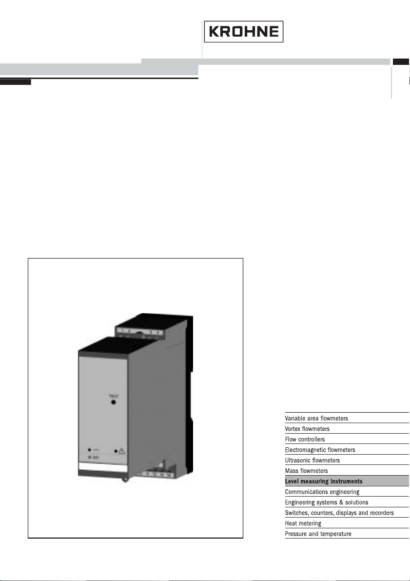
SU 501 Ex
Signal conditioning instrument
Page 2
Contents
Contents
1 About this document
1.1 Function .............................
1.2 Target group ..........................
1.3 Symbolism used .......................
2 For your safety
2.1 Authorised personnel ....................
2.2 Appropriate use........................
2.3 Warning about misuse ...................
2.4 General safety instructions ................
2.5 CE conformity .........................
2.6 Safety information for Ex areas.............
3 Product description
3.1 Configuration..........................
3.2 Principle of operation ....................
3.3 Adjustment ...........................
3.4 Storage and transport ...................
4 Mounting
4.1 General instructions .....................
4.2 Mounting information ....................
4
4
4
5
5
5
5
5
6
7
7
8
8
9
9
5 Connecting to power supply
5.1 Preparing the connection .................
5.2 Connection procedure ...................
5.3 Wiring plan ...........................
6 Set up
6.1 Adjustment system .....................
6.2 Adjustment elements ....................
7 Maintenance and fault rectification
7.1 Maintenance ..........................
7.2 Fault rectification .......................
7.3 Instrument repair .......................
8 Dismounting
8.1 Dismounting procedure ..................
8.2 Disposal .............................
9 Functional safety
9.1 General..............................
2 SU 501 Ex - Signal conditioning instrument
12
12
14
15
16
20
20
23
24
24
25
27953-EN-050616
Page 3

Contents
9.2 Planning .............................
9.3 Setup ...............................
9.4 Reaction during operation and in case of failure.
9.5 Recurring function test ...................
9.6 Safety-related characteristics ..............
10 Supplement
10.1 Technical data.........................
10.2 Dimensions ...........................
10.3 Certificate ............................
26
28
28
28
29
31
33
34
27953-EN-050616
SU 501 Ex - Signal conditioning instrument 3
Page 4
About this document
1 About this document
1.1 Function
This operating instructions manual has all the information you
need for quick setup and safe operation of SU 501 Ex. Please
read this manual before you start setup.
1.2 Target group
This operating instructions manual is directed to trained
personnel. The contents of this manual should be made
available to these personnel and put into practice by them.
1.3 Symbolism used
Information, tip, note
This symbol indicates helpful additional information.
Caution, warning, danger
This symbol informs you of a dangerous situation that could
occur. Ignoring this cautionary note can impair the person and/
or the instrument.
Ex applications
This symbol indicates special instructions for Ex applications.
l List
The dot set in front indicates a list with no implied sequence.
à Action
This arrow indicates a single action.
1 Sequence
Numbers set in front indicate successive steps in a procedure.
4 SU 501 Ex - Signal conditioning instrument
27953-EN-050616
Page 5
For your safety
2 For your safety
2.1 Authorised personnel
All operations described in this operating instructions manual
must be carried out only by trained specialist personnel
authorised by the operator. For safety and warranty reasons,
any internal work on the instruments must be carried out only
by personnel authorised by the manufacturer.
2.2 Appropriate use
SU 501 Ex is a universal signal conditioning instrument for
connection of a level switch.
2.3 Warning about misuse
Inappropriate or incorrect use of the instrument can give rise to
application-specific hazards, e.g. vessel overfill or damage to
system components through incorrect mounting or adjustment.
2.4 General safety instructions
SU 501 Ex is a high-tech instrument requiring the strict
observance of standard regulations and guidelines. The user
must take note of the safety instructions in this operating
instructions manual, the country-specific installation standards
(e.g. the VDE regulations in Germany) as well as all prevailing
safety regulations and accident prevention rules.
2.5 CE conformity
SU 501 ExisinCE conformity with EMC (89/336/EWG) and
NSR (73/23/EWG).
Conformity has been judged acc. to the following standards:
l EMC:
- Emission EN 50081-1: 1993
- Susceptibility EN 50082-2: 1995
l NSR: EN 61010-1: 1993
27953-EN-050616
SU 501 Ex - Signal conditioning instrument 5
Page 6

For your safety
2.6 Safety information for Ex areas
Please note the Ex-specific safety information for installation
and operation in Ex areas. These safety instructions are part of
the operating instructions manual and come with the Exapproved instruments.
6 SU 501 Ex - Signal conditioning instrument
27953-EN-050616
Page 7
3 Product description
3.1 Configuration
Product description
Scope of delivery
Components
The scope of delivery encompasses:
l SU 501 Ex signal conditioning instrument
l Documentation
- this operating instructions manual
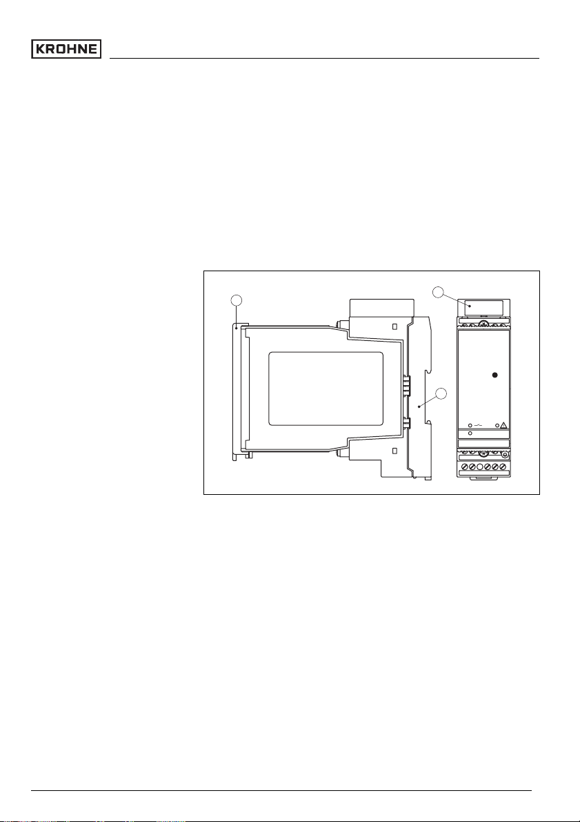
SU 501 Ex consists of the following components:
l SU 501 Ex signal conditioning instrument
3
Fig. 1: SU 501 Ex
1 Ex separating chamber with Ex version
2 Socket
3 Transparent cover
1
2
TEST
on
56 78
910 121314
3.2 Principle of operation
Area of application
Physical principle
Power supply
27953-EN-050616
SU 501 Ex - Signal conditioning instrument 7
SU 501 Ex is a single signal conditioning instrument for
processing of vibrating level switches.
SU 501 Ex signal conditioning instrument can power connected instruments and process their measuring signals.
You can find detailed information on the power supply in the
"Technical data" in the "Supplement".
Page 8

Product description
3.3 Adjustment
The integration time and the mode (A/B) can be preset on the
signal conditioning instrument via a DIL switch block.
A test key is lowered on the front plate of SU 501 Ex. When
pushing the key, the measuring system is checked on correct
function.
3.4 Storage and transport
Packaging
Storage and transport tempe-
rature
Your instrument was protected by packaging during transport.
Its capacity to handle normal loads during transport is assured
by a test acc. to DIN EN 24180.
The packaging of standard instruments consists of environ-
ment-friendly, recyclable cardboard. For special versions PE
foam or PE foil is also used. Dispose of the packaging material
via specialised recycling companies.
l Storage and transport temperature see "Supplement –
Technical data – Ambient conditions"
l Relative humidity 20 … 85 %
8 SU 501 Ex - Signal conditioning instrument
27953-EN-050616
Page 9
4 Mounting
4.1 General instructions
Mounting
Installation location
Transparent cover
SU 501 Ex signal conditioning instrument with plug-in socket
for mounting on carrier rail acc. to EN 50022.
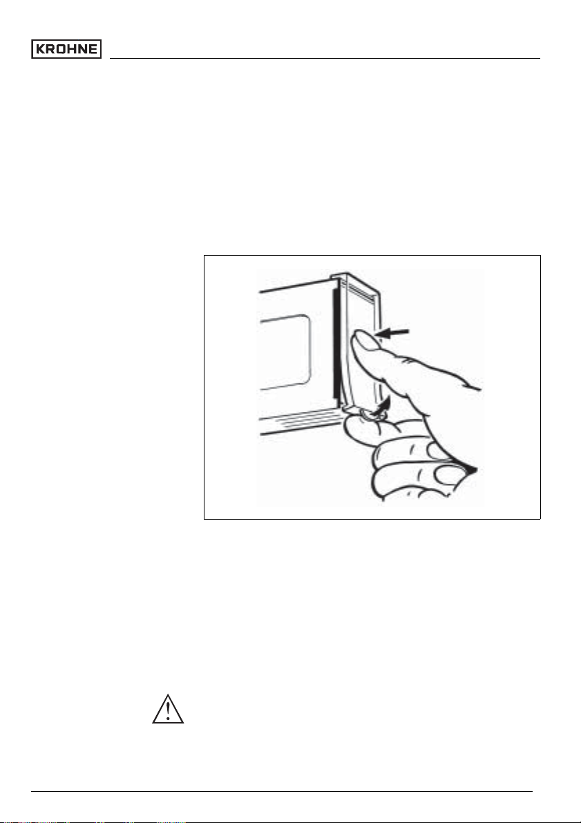
The front plate of SU 501 Ex can be provided with a lockable
transparent cover to protect the instrument against unauthorised adjustment. See the following figure for how to remove
the transparent cover.
Fig. 2: Removing the transparent cover
4.2 Mounting information
Mounting
27953-EN-050616
SU 501 Ex - Signal conditioning instrument 9
The plug-in socket is constructed for carrier rail mounting acc.
to EN 50022. Power supply is connected to terminals 9 and 10.
For neighbouring signal conditioning instruments, it is possible
to continue connection L1 and N directly via the supplied
bridges.
Danger:
The bridges must never be used with single instruments or at
the end of a row of instruments. If this rule is not heeded, there
is a danger of coming into contact with the operating voltage or
causing a short circuit.
Page 10
Mounting
ASU501 ExinEx version is an auxiliary, intrinsically safe
instrument and must not be installed in hazardous areas.
Ex separating chamber
Instrument coding
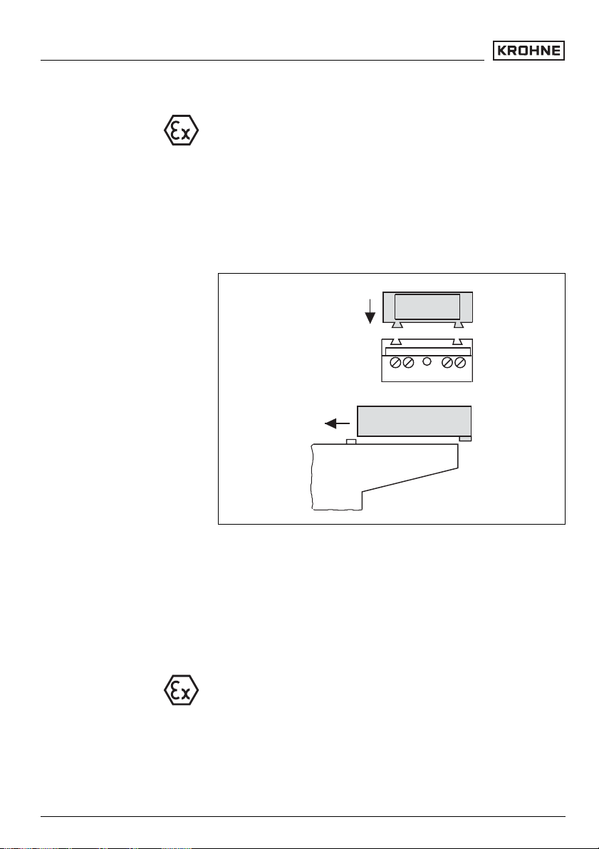
Before setup, the Ex separating chamber must be attached (as
shown below) with Ex versions. Safe operation can be only
ensured if the operating instructions manual and the EU type
approval certificate are observed. SU 501 Ex must not be
opened.
Close the upper terminals acc. to the following illustration.
12 43
Fig. 3: Mounting the separating chamber
All signal conditioning instruments are provided with different
gaps dependent on type and version (mechanical coding).
The plug-in socket is provided with coded pins that can be
inserted to prevent accidental interchanging of the various
instrument types.
With a SU 501 ExinEx version, the supplied coded pins (type
coded pin and Ex coded pin) must be inserted by the user acc.
to the below chart.
10 SU 501 Ex - Signal conditioning instrument
27953-EN-050616
Page 11
Mounting
4
3
2
1
EEx ia
A
B
Plug-in socket
C
Typ 600-1
1
2
3
0...10V
DISBUS
7
8
9
12
56 78
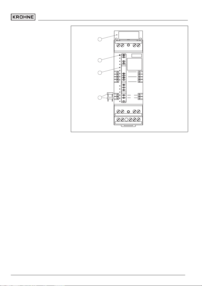
Fig. 4: Plug-in socket SU 501 Ex
1 Bridges for looping the power supply
2 Type coding for SU 501 Ex
3 Ex coding with Ex version
4 Ex separating chamber
4321
-
+
N
L
1
141312109
27953-EN-050616
SU 501 Ex - Signal conditioning instrument 11
Page 12

Connecting to power supply
5 Connecting to power supply
5.1 Preparing the connection
Note safety instructions
Take note of safety
instructions for Ex
applications
Select power supply
Select connection cable
Cable screening and groun-
ding
Always observe the following safety instructions:
l Connect only in the complete absence of line voltage
l If overvoltages are expected, overvoltage arresters should
be installed.
In hazardous areas you should take note of the appropriate
regulations, conformity and type approval certificates of the
sensors and power supply units.
The power supply can be 20 … 250 VAC, 50/60 Hzor
20 … 72 VDC.
Power supply of SU 501 Ex is connected with standard cable
acc. to the national installation standards.
Standard two-wire cable without screening can be used to
connect sensors. If electromagnetic interference is expected,
screened cable must be used.
Connect the cable screen on both ends to ground potential. In
the sensor, the screen must be connected directly to the
internal ground terminal. The ground terminal outside on the
sensor housing must be connected to the potential equalisation.
If potential equalisation currents are expected, the screen
connection on SU 501 Ex must be made via a ceramic
capacitor (e.g. 1 nF, 1500 V). The low frequency potential
equalisation currents are thus suppressed, but the protective
effect against high frequency interference signals remains.
Select connection
cable for Ex applications
Take note of the corresponding installation regulations for Ex
applications. In particular, make sure that no potential
equalisation currents flow over the cable screen. In case of
grounding on both sides this can be achieved by the use of a
capacitor or a separate potential equalisation.
5.2 Connection procedure
Move to electrical connection and proceed as follows:
1 Snap the socket without SU 501 Ex onto the carrier rail
12 SU 501 Ex - Signal conditioning instrument
27953-EN-050616
Page 13

Connecting to power supply
2 Connect sensor cable to terminal 1 and 2, and where
applicable, connect the screen
3 Connect power supply (switched off) to terminal 9 and 10
4 Insert SU 501 Ex into the plug-in socket and screw it down
tightly
The electrical connection is finished.
Before setting up Ex versions, make sure the Ex separating
chamber is plugged (above the sensor terminals). The pins for
type and Ex coding must also be inserted correctly.
27953-EN-050616
SU 501 Ex - Signal conditioning instrument 13
Page 14

Connecting to power supply
5.3 Wiring plan
Fig. 5: Wiring plan SU 501 Ex
1 Sensor
2 Sensor input
3 Transistor output
4 Relay output
5 Power supply
12 34
2
3
+-
56 78
910 121314
+
-
L1 N
5 4
1
14 SU 501 Ex - Signal conditioning instrument
27953-EN-050616
Page 15

6 Set up
6.1 Adjustment system
TEST
1
2
3
on
56 78
910 121314
4
EEx ia
A
B
Plug-in socket
C
Typ 600-1
1
2
3
7
8
9
12
56 78
0...10V
DISBUS
N
L
1
-
+
Set up
5
4321
6
7
7
8
9
141312109
10
Fig. 6: Indicating and adjustment elements
1 Test key
2 Control lamp level relay (LED)
3 Control lamp fail safe relay (LED)
4 Control lamp power supply (LED)
5 Ex separating chamber
6 Terminal for probe
7 Sockets for bridges
8 Transistor output
9 Relay output
10 Power supply
27953-EN-050616
SU 501 Ex - Signal conditioning instrument 15
Page 16

Set up
12
6
t sec
2
off
ze
za
123456
A
B
1
Control lamps
PTB-Nr.: Ex-95/xxxx X
Sensorstromkreis EEx ia IIC
Uo < xx V Lo < xx mH
< xx nF
Io < xx mA
Co
Po < xx mW
Sensor
Terminal
+
-
12
out
max: 36V
60mA
+
56
-
IP 30
nsp. I
max.250VAC/DC
500VA/54W
3AAC/1ADC
1312
: -20...+60°C
a
power supply
14
20...250 VAC
20...72VDC
L
N
+
-
910
2 W
23
Fig. 7: Indicating and adjustment elements
1 DIL switch block
2 Type label
3 Transparent cover
6.2 Adjustment elements
Control lamps (LED) in the front plate indicate operation,
switching status and fault signal.
l Green
- Operation control lamp
- Mains voltage on, instrument operates
l Red
- Failure lamp
- Fault on the sensor circuit by sensor failure or line
break
27953-EN-050616
16 SU 501 Ex - Signal conditioning instrument
Page 17
DIL switch block
Set up
- If the fail safe relay is deenergized, the red failure lamp
will light
l Yellow
- Relay control lamp
- The yellow relay control lamp reacts depending on the
set mode (A/B)
- In general, the relay control lamp indicates the
activated (energised) condition of the relay
- A dark relay control lamp means that the relay is
deenergised (transistor blocks)
Laterally on top (covered when mounted) there is a DIL switch
block with six switches. The individual switches are assigned
as follows:
l 1 – A/B mode
- A – Max. detection or overfill protection
- B – Min. detection or dry run detection
l 2 – Switch off delay (za)
l 3 – Switch on delay (ze)
l 4 – Integration time 2 s
l 5 – Integration time 6 s
l 6 – Integration time 12 s
With switch 1 you can adjust the mode (A – overfill protection
or B – dry run protection).
With switch 2 and 3 you can adjust the switch off and/or switch
on delay independently.
In the example (see previous illustration), mode A (max.
detection of overfill protection) is selected (switch 1). The
switch on delay is activated (switch 3 ) and the integration time
is set to 8 seconds (switch 4, 5 and 6).
With switches 4, 5 and 6 you can adjust the integration time.
The times of the activated time switches accumulate. If the
switch on (ze) and switch off delay (za) are switched on
together, the adjusted time applies to both delay modes.
Information:
Keep in mind that the integration time of the sensor and signal
conditioning instrument accumulate.
27953-EN-050616
SU 501 Ex - Signal conditioning instrument 17
Page 18

Set up
Switch 12345 6
Time za ze 2 s 6 s 12 s
0.2 s A/B off off off off off
0.5 s A/B
2 s A/B on off off
6 s A/B off on off
8 s A/B on on off
12 s A/B off off on
14 s A/B on off on
18 s A/B off on on
20 s A/B on on on
1)
off off off
Fault monitoring
Test key
The measuring system is continuously monitored. The
following criteria are checked:
l Two-wire cable on line break and shortcircuit
l Interruption of the connection cable to the piezo elements
l Corrosion or damage of the tuning fork (vibrating rod)
l Break of the tuning fork (vibrating rod)
l no vibration
l Too low vibrating frequency
l Medium penetrating from the vessel side into the sensor
In systems with OPTISWITCH level switches in conjunction
with a two-wire oscillator, a function test can be carried out. SU
501 Ex has an integrated test key. The test key is lowered in
the front plate of the signal conditioning instrument. Push the
test key with a suitable object (e.g. screwdriver, pen etc.).
By pushing the key, the system is checked on the following
criteria:
l Switching function of the switching outputs
l Potential separation of the outputs
l The signal processing of the signal conditioning instrument
After pushing the test key, the complete measuring system is
checked on correct function. The following operating conditions are simulated during the test:
l Fault signal
l Empty signal
27953-EN-050616
1)
Set alternately switch 2 and/or 3 to "on". The times apply to the adjusted
delay mode.
18 SU 501 Ex - Signal conditioning instrument
Page 19

Set up
l Full signal
Check if all three switching conditions occur in the correct
sequence and the stated duration. If not, there is a fault in the
measuring system (see chapter "Fault rectification").
Note:
Keep in mind that the connected instruments are activated
during the function test. By doing this, you can check the
correct function of the measuring system.
Test procedure A-mode B-mode
1 Simulation of a fault signal (approx. 3 s)
Level relay deenergised Relay control
lamp off
1 Simulation of a fault signal
Failure lamp Failure lamp
lights
2 Simulation an empty signal (approx. 1.5 s)
Level relay energised Relay control
lamp lights
2 Simulation of an empty signal
Failure lamp Failure lamp off Failure lamp off
3 Simulation of a full signal (approx. 1.5 s)
Level relay deenergised Relay control
lamp off
3 Simulation of a full signal
Failure lamp Failure lamp off Failure lamp off
4 Return to the current operating condition (covered/uncovered)
Relay control
lamp off
Failure lamp
lights
Relay control
lamp off
Relay control
lamp lights
27953-EN-050616
SU 501 Ex - Signal conditioning instrument 19
Page 20

Maintenance and fault rectification
7 Maintenance and fault rectification
7.1 Maintenance
When used as directed in normal operation, SU 501 Exis
completely maintenance-free.
7.2 Fault rectification
Causes of malfunction
Fault rectification
Failure
SU 501 Exoffers maximum reliability. Nevertheless faults can
occur during operation. These may be caused by the following,
e.g.:
l Measured value of the sensor not correct
l Power supply
l Interference on the cables
The first measures are checking the input and output signal.
The procedure is described as follows. In many cases the
causes can be determined and faults can be rectified.
? The red failure LED of the signal conditioning instrument
lights
l Sensor not connected correctly
à Measure the current value on the signal cable to the
sensor
In Ex systems, make sure that the Ex protection is not
influenced by the measuring instruments used.
à Faults on the sensor causing a current change below
2 mA or above 23 mA, cause a fault signal on
measuring instruments.
20 SU 501 Ex - Signal conditioning instrument
27953-EN-050616
Page 21

Maintenance and fault rectification
12... 20V4... 20mA
VmA
+
-
2
Fig. 8: Connection of a multimeter
1 SU 501 Ex signal conditioning instrument
2 Sensor
1
12 34
l Sensor not connected correctly
à Measure the voltage on the connection cable
In Ex systems, make sure that the Ex protection is not
influenced by the measuring instruments used.
à The terminal voltage of the sensor is at least 12 V in
normal condition
? The red failure LED of the signal conditioning instrument
lights
l Current value <2 mA
à Measure the current value on the signal cable to the
sensor
1 Check all connections and connection cables to the sensor
The voltage should be approx. 17 … 20 V
If the value is below 17 V, probably the signal conditioning
instrument is defective.
Exchange signal conditioning instrument or return it for
repair
2 If the red failure lamp continues to light, separate the
sensor from the connection cable and connect a resistor of
1 kOhm instead on the signal conditioning instrument
The signal conditioning instrument is defective if the failure
lamp continues to light
27953-EN-050616
SU 501 Ex - Signal conditioning instrument 21
Page 22

Maintenance and fault rectification
Exchange signal conditioning instrument or return it for
repair
3 Should the failure lamp extinguish, you can connect the
sensor again. Separate the signal conditioning instrument
from the connection cable and connect a resistor of 1
kOhm to the sensor input
4 If the failure lamp continues to light, the connection cable is
probably interrupted
Check the connection cable to the sensor
5 Should the failure lamp extinguish, the sensor will be
defective
Exchange sensor or return it for repair
? The red failure LED of the signal conditioning instrument
lights
l Current value >22 mA
à Measure the current value on the signal cable to the
sensor
1 Check all connections and connection cables to the sensor
2 If the red failure lamp continues to light, separate the
sensor from the connection cable and connect a resistor of
1 kOhm instead on the signal conditioning instrument
If the failure lamp extinguishes, the sensor is defective.
Check the connected sensor
3 If the failure lamp continues to light, connect the sensor
again. Separate signal conditioning instrument from the
connection cable and connect a resistor of 1 kOhm to the
sensor input.
4 If the failure lamp extinguishes, this is probably due to a
shortcircuit in the connection cable
Check the connection cable to the sensor
5 If the failure lamp continues to light, the signal conditioning
instrument is defective
Exchange signal conditioning instrument or return it for
repair
27953-EN-050616
22 SU 501 Ex - Signal conditioning instrument
Page 23

Maintenance and fault rectification
? Malfunction during function test
l After pushing the test key, the switching conditions do
not occur in the correct sequence or correct duration, e.
g. no full signal is outputted.
à Measure the line resistance
à If the cable is highly resistive, bring it to a normal
resistance, e.g. check terminals and cable connections
on corrosion
7.3 Instrument repair
If a repair is necessary, please proceed as follows:
You can download a return form from our Internet homepage
http://www.krohne-mar.com/fileadmin/media-lounge/PDF-
Download/Specimen_e.pdf.
By doing this you help us carry out the repair quickly and
without having to call back for needed information.
l Print and fill out one form per instrument
l Clean the instrument and pack it damage-proof
l Attach the completed form and possibly also a safety data
sheet to the instrument.
27953-EN-050616
SU 501 Ex - Signal conditioning instrument 23
Page 24

Dismounting
8 Dismounting
8.1 Dismounting procedure
Warning:
Before dismounting, be aware of dangerous process conditions such as e.g. pressure in the vessel, high temperatures,
corrosive or toxic products etc.
Take note of chapters "Mounting" and "Connecting to power
supply" and carry out the listed steps in reverse order.
8.2 Disposal
SU 501 Ex consists of materials which can be recycled by
specialised recycling companies. We have purposely designed the electronic modules to be easily separable. Mark the
instrument as scrap and dispose of it according to government
regulations (electronic scrap ordinance,…).
Materials: see "Technical data"
If you cannot dispose of the instrument properly, please
contact us about disposal methods or return.
24 SU 501 Ex - Signal conditioning instrument
27953-EN-050616
Page 25

9 Functional safety
9.1 General
Functional safety
Validity
Area of application
Safety function
Relevant standards
Safety requirements
This safety manual applies to the SU 501 Ex signal
conditioning instrument. The instrument corresponds to a part
system of type A.
In combination with a vibrating level switch, the signal
conditioning instrument can be used as measuring system for
level detection meeting the special requirements of the safety
technology, e.g.
l Mode "max."=A-mode for overfill protection
l Mode "min."=B-mode for dry run protection
The measuring system is qualified in both modes to meet the
following requirement degree acc. to IEC 61508-2/IEC 61511:
l SIL2 with architecture 1oo1D (single channel)
l SIL3 with architecture 1oo2D (double-channel/redundant)
The safety function of the signal conditioning instrument is the
recognition of the meas. currents stated below and the
conversion into a respective switching signal on the relay
contact or the transistor output. The safe condition depends on
the mode:
l In mode "max.": 16 ±1 mA for condition "covered"
l In mode "min.": 8 ±1 mA for condition "uncovered"
l IEC 61508-1,-2,-4
- Functional safety of electrical/electronic/programmable
electronic systems
l IEC 61511-1
- Functional safety – safety instrumented systems for the
process industry sector – Part 1: Framework, definitions, system, hardware and software requirements
The failure limit values for a safety function, depending on the
SIL class (of IEC 61508-1, 7.6.2)
Safety integrity level Low demand mode High demand mode
SIL PFD
4 >=10
3 >=10-4up to <10
2 >=10-3up to <10
1 >=10-2up to <10
avg
-5
up to <10
-4
-3
-2
-1
PFH
>=10-9up to <10
>=10-8up to <10
>=10-7up to <10
>=10-6up to <10
27953-EN-050616
SU 501 Ex - Signal conditioning instrument 25
-8
-7
-6
-5
Page 26

Functional safety
Safety integrity of the hardware for safety-relating subsystems
of type A (IEC 61508-2, 7.4.3)
General instructions and
restrictions
Assumptions
Low demand mode
Safe failure fraction Hardware
fault tolerance
SFF HFT = 0 HFT = 1 HFT = 2
<60 % SIL1 SIL1 SIL2
60 % up to <90 % SIL2 SIL3 (SIL4)
90 % up to <99 % SIL3 (SIL4)(SIL4)
>=99 % SIL3 (SIL4)(SIL4)
9.2 Planning
l The measuring system must be used acc. to the
application
l The application-specific limits must be maintained and the
specifications must not be exceeded.
l Acc. to the specifications in the operating instructions
manual, the current load of the output circuits must be
within the limits.
For the implementation of FMEDA (Failure Mode, Effects and
Diagnostics Analysis) the following assumptions form the
basis:
l Failure rates are constant, wear of the mechanical parts is
not taken into account
l Failure rates of external power supplies are not included
l Multiple errors are not taken into account
l The average ambient temperature during the operating
time is +40°C (104°F)
l The environmental conditions correspond to an average
industrial environment
l The lifetime of the components is around 8 to 12 years
(IEC 61508-2, 7.4.7.4, remark 3)
l The condition of the output circuit is further processed acc.
to the quiescent current principle
l The repair time (exchange of the meas. system) after a fail-
safe error is eight hours (MTTR = 8 h)
If the demand rate is only once a year, then the measuring
system can be used as safety-relevant subsystem in "low
demand mode" (IEC 61508-4, 3.5.12).
27953-EN-050616
26 SU 501 Ex - Signal conditioning instrument
Page 27

Functional safety
If the ratio of the internal diagnostics test rate of the measuring
system to the demand rate exceeds the value 100, the
measuring system can be treated in the way it is executing a
safety function in the mode with low demand rate (IEC 61508-2,
7.4.3.2.5).
Corresponding characteristics is the value PFD
(average
avg
Probability of dangerous Failure on Demand). It is dependent
on the test interval T
between the function tests of the
Proof
protective function.
Numbers see paragraph "Safety-technical characteristics".
High demand mode
Safe condition and fault
description
Configuration of the proces-
sing unit
If the "low demand mode" does not apply, the measuring
system must be used as safety-relevant subsystem in "high
demand" (IEC 61508-4, 3.5.12).
The fault tolerance time of the complete system must be higher
than the sum of the reaction times or the diagnostics test
periods of all components in the safety chain.
Corresponding characteristics is the value PFH (failure rate).
Numbers see paragraph "Safety-technical characteristics".
The safe condition of the measuring system is the switched off
status (quiescent current principle):
l Relay output – relay deenergised
l Transistor output – transistor blocks
A fail-safe failure (safe failure) exists if the measuring system
changes to the defined safe condition without demand of the
process.
If the signal conditioning instrument detects currents <3.6 mA
or >21.6 mA, the signal conditioning instrument takes on the
safe condition.
A dangerous undetected failure exists if the measuring system
does not go to the defined safe condition when required by the
process.
The processing unit must evaluate the output circuit of the
measuring system by taking the quiescent current principle
into account.
The processing unit must correspond to the SIL level of the
measuring chain.
27953-EN-050616
SU 501 Ex - Signal conditioning instrument 27
Page 28

Functional safety
9.3 Setup
Mounting and installation
The prevailing plant conditions influence the safety of the
measuring system. Therefore note the mounting and installation instructions of the appropriate operating instructions
manual. Mainly important is the correct setting of the mode
(min./max.).
9.4 Reaction during operation and in case of
failure
l The adjustment elements must not be modified during
operation.
l In case of modifications during operation, you have to take
note of the safety functions.
l Occurring fault signals are described in the appropriate
operating instructions manual.
l In case of detected failures or fault signals, the entire
measuring system must be switched out of service and the
process held in a safe condition by means of other
measures.
l The manufacturer must be informed if due to a determined
fault, the instrument will be exchanged (incl. a fault
description)
9.5 Recurring function test
The recurring function test serves to reveal potential dangerous errors that are otherwise not discernible. The function of
the measuring system must be checked at adequate intervals.
The operator is responsible for choosing the type of test and
the intervals in the stated time frame. The time frame depends
on the PFD
"Safety-related characteristics".
With high demand rate, a recurring function test is not
requested in IEC 61508. The function of the measuring system
is proven by the frequent use of the system. In double channel
architectures it is useful to proof the redundancy by recurring
function tests in appropriate intervals.
The test must be carried out in a way that verifies the flawless
operation of the safety functions in conjunction with all system
components.
value acc. to the chart and diagram in section
avg
27953-EN-050616
28 SU 501 Ex - Signal conditioning instrument
Page 29

Functional safety
The methods and procedures used during the tests must be
stated and their suitability must be specified. The tests must be
documented.
If the function test proves negative, the entire measuring
system must be switched out of service and the process held
in a safe condition by means of other measures.
In the double channel architecture 1oo2D this applies
separately to both channels.
9.6 Safety-related characteristics
The failure rates of the electronics are determined by an
FMEDA acc. to IEC 61508. These calculations are based on
component failure rates acc. to SN 29500. All numerical values
refer to an average ambient temperature during the operating
time of +40°C (104°F). The calculations are also based on the
specifications stated in chapter "Planning".
The data are also valid for overfill protection (A-mode) as well
as dry run protection (B-mode).
λ
sd
λ
su
λ
dd
λ
du
SFF >84 % Safe Failure Fraction
0 FIT safe detected failure (1 FIT = failure/109h)
516 FIT safe undetected failure
0 FIT dangerous detected failure
100 FIT dangerous undetected failure
General data
Failure reaction time 0.5 sec
T
Reaction
MTBF = MTTF + MTTR 1.52x10
max. useful life of the measuring system for the safety
function
approx. 10 years
Single channel architecture
The following characteristics are derived from the above
mentioned data:
SIL2 (Safety Integrity Level)
HFT = 0 (Hardware Fault Tolerance)
27953-EN-050616
SU 501 Ex - Signal conditioning instrument 29
6
h
Page 30

Functional safety
Architecture 1oo1D
PFD
avg
T
= 1 year
Proof
T
= 5 years
Proof
T
= 10 years
Proof
PFH <0.1x10⁻⁶/h
<0.044x10
<0.218x10
<0.436x10
-2
-2
-2
Double channel architecture
If the measuring instrument is used in a double channel
architecture, the safety-relevant characteristics of the selected
structure of the measuring chain must be calculated acc. to the
above failure rates (especially for the selected application). A
Common Cause Factor must be taken into account which is in
the worst case 10 %.
The following is applicable:
SIL3 (Safety Integrity Level)
HFT = 1 (Hardware Fault Tolerance)
Time-dependent process of
PFD
avg
The time-dependent process of PFD
reacts in the time
avg
period up to 10 years virtually linear to the operating time. The
above values only apply to the T
interval, after which a
Proof
recurring function test must be carried out.
PFD
avg
4
3
2
1
1510
Fig. 9: Time-dependent process of PFD
1 PFD
2 PFD
3 PFD
4 PFD
2)
= 0
avg
after 1 year
avg
after 5 years
avg
after 10 years
avg
Numbers see in the above charts.
2)
avg
T
Proof
27953-EN-050616
30 SU 501 Ex - Signal conditioning instrument
Page 31

Supplement
10 Supplement
10.1 Technical data
General data
Series module unit with plug-in socket for mounting on
carrier rail 35x7.5 or 35x5 acc. to EN 50022
Dimensions W = 36 mm (1.42 in), H = 118.5 mm (4.66 in), D
= 134 mm (5.28 in)
Weight approx. 170 g (6 oz)
Housing material Noryl SE100, Lexan 920A
Socket material Noryl SE100, Noryl SE1 GFN3
Screw terminals max. 1x1.5 mm²
Power supply
Power supply 20 … 250 VAC, 50/60 Hz, 20 … 72 VDC
Power consumption max. 3 W (3 … 18 VA)
Sensor input
Quantity 1
Data transmission Analogue
Hysteresis 100 µA
Switching threshold 12 mA
Current limitation 24 mA (permanently short-circuit proof)
Sensor power supply 15 … 18 VDC
Detection line break <=3.6 mA
Detection shortcircuit >=21 mA
Connection cable 2-wire
Resistance per conductor max. 35 Ohm
Relay output
Number, function 1x switching relay (spdt)
Integration time 0.2 … 20 s, directional switching
Mode A/B switch (A - max. detection or overfill
protection; B - min. detection or dry run
protection)
Contact 1x spdt
Contact material AgNi, hard gold-plated
Turn-on voltage min. 10 mVDC, max. 250 VAC, 250 VDC
Switching current min. 10 µADC, max. 3 AAC, 1 ADC
Breaking capacitance max. 500 VA, max. 54 WDC
27953-EN-050616
SU 501 Ex - Signal conditioning instrument 31
Page 32

Supplement
Transistor output
Number, function 1 output, synchronously switching with the
relay
Galvanic separation floating
Max. values
- U
B
- I
B
Transistor voltage loss U
max. 36 VDC
max. 60 mA (short-circuit proof)
min.-1.5 V at IB60 mA
CE
Blocking current <10 µA
Adjustment elements
DIL switch block for preadjustment of the integration time and
mode
Test key for function test
Control lamps in the front plate
- status indication operating voltage LED green
- Status indication fault signal LED red
- Status indication switching point
LED yellow
control
Ambient conditions
Ambient temperature -20 … +60°C (-4 … +140°F), with an operating
voltage of 60 … 72 VDCthe permissible
ambient temperature reduces linear from
+60°C (+140°F) to +40°C (+104°F)
Storage and transport temperature -40 … +70°C (-40 … +158°F)
Electrical protective measures
Protection
- Signal conditioning instrument IP 30
- Socket IP 20
Overvoltage category II
Protection class II
Electrical separating measures reliable separation (VDE 0106, part 1) between
power supply, meas. data input, level relay and
transistor output
Approvals
3)
ATEX ATEX II (1) GD [EExia] IIC
Others WHG
3)
Deviating data with Ex applications: see separate safety instructions.
32 SU 501 Ex - Signal conditioning instrument
27953-EN-050616
Page 33

10.2 Dimensions
1
Supplement
134mm (5
9
/
")
32
Fig. 10: Dimensions SU 501 Ex
1 Transparent cover
2 Carrier rail 35x7.5 or 35x15 acc. to EN 50022
2
")
64
/
9
54,5mm (2
on
56 78
910 121314
27
/
36mm (1
")
64
")
64
/
43
118,5mm (4
27953-EN-050616
SU 501 Ex - Signal conditioning instrument 33
Page 34

10.3 Certificate
CE declaration of conformity
Fig. 11: CE declaration of conformity
34 SU 501 Ex - Signal conditioning instrument
27953-EN-050616
Page 35

27953-EN-050616
SU 501 Ex - Signal conditioning instrument 35
Page 36

Subject to change without notice
27953-EN-050616
 Loading...