

Page 1

OPTISYS SLM 2100
OPTISYS SLM 2100
OPTISYS SLM 2100OPTISYS SLM 2100
Sludge level meter
Software Revision:
01.00.01
Original handbook
Handbook
Handbook
HandbookHandbook
© KROHNE 03/2014 - 4002737302 - MA OPTISYS SLM 2100 R02 en
Page 2

: IMPRINT :::::::::::::::::::::::::::::::::::::::
All rights reserved. It is prohibited to reproduce this documentation, or any part thereof, without
the prior written authorisation of KROHNE Messtechnik GmbH.
Subject to change without notice.
Copyright 2014 by
KROHNE Messtechnik GmbH - Ludwig-Krohne-Str. 5 - 47058 Duisburg (Germany)
2
www.krohne.com 03/2014 - 4002737302 - MA OPTISYS SLM 2100 R02 en
Page 3

OPTISYS SLM 2100
CONTENTS
1 Safety instructions 5
1.1 Software history ............................................................................................................... 5
1.2 Intended use ..................................................................................................................... 5
1.3 Certifications .................................................................................................................... 6
1.4 Safety instructions from the manufacturer ..................................................................... 7
1.4.1 Copyright and data protection ................................................................................................ 7
1.4.2 Disclaimer ............................................................................................................................... 7
1.4.3 Product liability and warranty ................................................................................................ 8
1.4.4 Information concerning the documentation........................................................................... 8
1.4.5 Warnings and symbols used................................................................................................... 9
1.5 Safety instructions for the operator................................................................................. 9
2 Device description 10
2.1 Scope of delivery............................................................................................................. 10
2.2 Device description .......................................................................................................... 11
2.3 Nameplate ...................................................................................................................... 13
3 Installation 14
3.1 General notes on installation ......................................................................................... 14
3.2 Storage and transport .................................................................................................... 14
3.3 Installation order............................................................................................................ 15
3.3.1 Mounting of the sludge level meter...................................................................................... 16
3.4 Typical measuring point ................................................................................................. 18
3.5 Installing the cleaning unit (optional) ............................................................................ 19
3.5.1 Installation of the water hose ............................................................................................... 20
4 Electrical connections 21
4.1 Safety instructions.......................................................................................................... 21
4.2 Used abbreviations .........................................................................................................21
4.3 Description of electrical symbols................................................................................... 22
4.4 Important device-specific notes on electrical connection............................................. 23
4.5 Overview cable connections ........................................................................................... 24
4.6 Overview of the terminal compartment ......................................................................... 25
4.7 Connecting the power supply......................................................................................... 26
4.8 Description and properties of the outputs and the input............................................... 27
4.8.1 Current output ...................................................................................................................... 27
4.8.2 Control input (active)............................................................................................................. 28
4.9 Connection of the outputs and the input........................................................................ 29
4.9.1 Important notes..................................................................................................................... 29
4.9.2 Current output (active).......................................................................................................... 30
4.9.3 Electrical connection of control inputs................................................................................. 31
4.10 Description and properties of the relays ..................................................................... 33
4.10.1 Connection of the relays ..................................................................................................... 33
4.11 Electrical connection of the external pump................................................................. 35
4.12 Protection category ...................................................................................................... 35
www.krohne.com03/2014 - 4002737302 - MA OPTISYS SLM 2100 R02 en
3
Page 4

CONTENTS
OPTISYS SLM 2100
5 Operation 36
5.1 Start-up and general remarks for configuration........................................................... 36
5.2 Switching on the power .................................................................................................. 37
5.3 Operating elements........................................................................................................ 38
5.4 Measuring page .............................................................................................................. 39
5.4.1 Navigating through the menus .............................................................................................40
5.5 Menu mode structure..................................................................................................... 44
5.6 Function tables ............................................................................................................... 45
5.6.1 Menu A, quick setup.............................................................................................................. 45
5.6.2 Menu B, test .......................................................................................................................... 45
5.6.3 Menu C, setup ....................................................................................................................... 46
5.7 Functions in detail .......................................................................................................... 51
5.7.1 Definition of positions and zones.......................................................................................... 51
5.7.2 Measuring function ............................................................................................................... 52
5.7.3 Measuring mode ................................................................................................................... 52
5.7.4 Definition of fluff and blanket concentration........................................................................ 53
5.7.5 Definition in zone tracking mode.......................................................................................... 53
5.7.6 Rake guard / external trigger ............................................................................................... 53
5.7.7 Timer / start signal ............................................................................................................... 54
5.7.8 Extended settings.................................................................................................................. 54
5.7.9 Calibration............................................................................................................................. 55
5.7.10 Passwords........................................................................................................................... 58
5.7.11 Timeout function ................................................................................................................. 58
5.8 Status messages and diagnostic information................................................................ 59
5.8.1 Error category "Device failure" (bold "F")............................................................................ 60
5.8.2 Error category "Application error" ( "F", not bold) .............................................................. 61
5.8.3 Error category "Information" (I) ........................................................................................... 61
5.8.4 Error category "Out of specification" (S) .............................................................................. 61
6 Service 62
6.1 Manual initiation of a measurement .............................................................................. 62
6.2 Maintenance ................................................................................................................... 62
6.2.1 Cleaning unit (optional)......................................................................................................... 64
6.3 Spare parts availability...................................................................................................65
6.4 Availability of services .................................................................................................... 65
6.5 Returning the device to the manufacturer..................................................................... 65
6.5.1 General information.............................................................................................................. 65
6.5.2 Form (for copying) to accompany a returned device............................................................ 66
6.6 Disposal .......................................................................................................................... 66
7 Technical data 67
7.1 Measuring principle........................................................................................................67
7.2 Technical data................................................................................................................. 68
7.3 Dimensions ..................................................................................................................... 72
8 Notes 73
4
www.krohne.com 03/2014 - 4002737302 - MA OPTISYS SLM 2100 R02 en
Page 5

OPTISYS SLM 2100
1.1 Software history
INFORMATION!
This documentation explains the installation and operation of the OPTISYS SLM 2100 sludge
level meter.
Release date Software version Documentation
04/2013 01.00.01 MA OPTISYS SLM 2100 R02 en
1.2 Intended use
The OPTISYS SLM 2100 sludge level meter is primarily designed for use in water and waste
water treatment plants. There it determines the sedimentation profile in clarifiers and sludge
thickeners and detects sludge blanket or fluff level. For this it measures the suspended solids
concentration and height of the sensor above ground as the sensor is lowered into the basin or
tank.
However, the design of the OPTISYS SLM 2100 makes it possible to use it in other applications
where reliable monitoring of interface or stratification in suspensions is necessary.
SAFETY INSTRUCTIONS 1
The OPTISYS SLM 2100 shall not be used in hazardous areas, which e.g. require Ex approvals. It
could ignite gases. Additionally, due to the sensors material, the meter shall not be used in
applications with a high concentration of salt (e.g. seawater). The device has been constructed
for indoor and outdoor use below the maximum altitude of 2000 m / 6562 ft.
By observing the operation instructions, national standards, safety requirements and accident
prevention regulations the residual risk is reduced to an acceptable level.
www.krohne.com03/2014 - 4002737302 - MA OPTISYS SLM 2100 R02 en
5
Page 6

1 SAFETY INSTRUCTIONS
1.3 Certifications
CE marking
The device fulfils the statutory requirements of the following EC directives:
• Electromagnetic compatibility (EMC) in accordance with directive 2004/108/EC:
EN 61000-6-4 2007 Electromagnetic compatibility (EMC) - Part 6-4: Generic standards -
Emission standard for industrial environments
EN 61000-6-3:2007 Electromagnetic compatibility (EMC) - Part 6-3: Generic standards Emission standard for residential, commercial and light-industrial environments
EN 61000-6-2:2005 Electromagnetic compatibility (EMC) - Part 6-2: Generic standards Immunity for industrial environments
EN 61326-1:2013 Electrical equipment for measurement, control and laboratory use - EMC
requirements - Part 1: General requirements
• Low voltage directive according to directive 2006/95/EC:
EN 61010-1:2011 Safety requirements for electrical equipment for measurement, control,
and laboratory use (Part 1: General requirements)
• Directive for machinery 2006/42/EC in accordance with:
EN 60204-1:2006 Safety of machinery - Electrical equipment of machines (Part 1: General
requirements)
EN 953:1997+A1:2009 Safety of machinery - Guards - General requirements for the design
and construction of fixed and movable guards
• Directive on the restriction of the use of certain hazardous substances in electrical and
electronic equipment in accordance with directive 2011/65/EU
OPTISYS SLM 2100
The manufacturer certifies successful testing of the product by applying the CE marking.
6
www.krohne.com 03/2014 - 4002737302 - MA OPTISYS SLM 2100 R02 en
Page 7

OPTISYS SLM 2100
1.4 Safety instructions from the manufacturer
1.4.1 Copyright and data protection
The contents of this document have been created with great care. Nevertheless, we provide no
guarantee that the contents are correct, complete or up-to-date.
The contents and works in this document are subject to copyright. Contributions from third
parties are identified as such. Reproduction, processing, dissemination and any type of use
beyond what is permitted under copyright requires written authorisation from the respective
author and/or the manufacturer.
The manufacturer tries always to observe the copyrights of others, and to draw on works created
in-house or works in the public domain.
The collection of personal data (such as names, street addresses or e-mail addresses) in the
manufacturer's documents is always on a voluntary basis whenever possible. Whenever
feasible, it is always possible to make use of the offerings and services without providing any
personal data.
SAFETY INSTRUCTIONS 1
We draw your attention to the fact that data transmission over the Internet (e.g. when
communicating by e-mail) may involve gaps in security. It is not possible to protect such data
completely against access by third parties.
We hereby expressly prohibit the use of the contact data published as part of our duty to publish
an imprint for the purpose of sending us any advertising or informational materials that we have
not expressly requested.
1.4.2 Disclaimer
The manufacturer will not be liable for any damage of any kind by using its product, including,
but not limited to direct, indirect or incidental and consequential damages.
This disclaimer does not apply in case the manufacturer has acted on purpose or with gross
negligence. In the event any applicable law does not allow such limitations on implied warranties
or the exclusion of limitation of certain damages, you may, if such law applies to you, not be
subject to some or all of the above disclaimer, exclusions or limitations.
Any product purchased from the manufacturer is warranted in accordance with the relevant
product documentation and our Terms and Conditions of Sale.
The manufacturer reserves the right to alter the content of its documents, including this
disclaimer in any way, at any time, for any reason, without prior notification, and will not be liable
in any way for possible consequences of such changes.
www.krohne.com03/2014 - 4002737302 - MA OPTISYS SLM 2100 R02 en
7
Page 8

1 SAFETY INSTRUCTIONS
1.4.3 Product liability and warranty
The operator shall bear responsibility for the suitability of the device for the specific purpose.
The manufacturer accepts no liability for the consequences of misuse by the operator. Improper
installation and operation of the devices (systems) will cause the warranty to be void. The
respective "Standard Terms and Conditions" which form the basis for the sales contract shall
also apply.
1.4.4 Information concerning the documentation
To prevent any injury to the user or damage to the device it is essential that you read the
information in this document and observe applicable national standards, safety requirements
and accident prevention regulations.
If this document is not in your native language and if you have any problems understanding the
text, we advise you to contact your local office for assistance. The manufacturer can not accept
responsibility for any damage or injury caused by misunderstanding of the information in this
document.
This document is provided to help you establish operating conditions, which will permit safe and
efficient use of this device. Special considerations and precautions are also described in the
document, which appear in the form of underneath icons.
OPTISYS SLM 2100
8
www.krohne.com 03/2014 - 4002737302 - MA OPTISYS SLM 2100 R02 en
Page 9

OPTISYS SLM 2100
1.4.5 Warnings and symbols used
Safety warnings are indicated by the following symbols.
DANGER!
This warning refers to the immediate danger when working with electricity.
DANGER!
This warning refers to the immediate danger of burns caused by heat or hot surfaces.
DANGER!
This warning refers to the immediate danger when using this device in a hazardous atmosphere.
DANGER!
These warnings must be observed without fail. Even partial disregard of this warning can lead to
serious health problems and even death. There is also the risk of seriously damaging the device
or parts of the operator's plant.
SAFETY INSTRUCTIONS 1
WARNING!
Disregarding this safety warning, even if only in part, poses the risk of serious health problems.
There is also the risk of damaging the device or parts of the operator's plant.
CAUTION!
Disregarding these instructions can result in damage to the device or to parts of the operator's
plant.
INFORMATION!
These instructions contain important information for the handling of the device.
LEGAL NOTICE!
This note contains information on statutory directives and standards.
• HANDLING
HANDLING
HANDLINGHANDLING
This symbol designates all instructions for actions to be carried out by the operator in the
specified sequence.
i RESULT
RESULT
RESULTRESULT
This symbol refers to all important consequences of the previous actions.
1.5 Safety instructions for the operator
WARNING!
In general, devices from the manufacturer may only be installed, commissioned, operated and
maintained by properly trained and authorized personnel.
This document is provided to help you establish operating conditions, which will permit safe and
efficient use of this device.
www.krohne.com03/2014 - 4002737302 - MA OPTISYS SLM 2100 R02 en
9
Page 10

2 DEVICE DESCRIPTION
2.1 Scope of delivery
INFORMATION!
Inspect the packaging carefully for damages or signs of rough handling. Report damage to the
carrier and to the local office of the manufacturer.
INFORMATION!
Do a check of the packing list to make sure that you have all the elements given in the order.
INFORMATION!
Look at the device nameplate to ensure that the device is delivered according to your order.
Check for the correct supply voltage printed on the nameplate.
OPTISYS SLM 2100
Figure 2-1: Scope of delivery
1 Sludge level meter
2 Brackets for round / rectangular handrail
3 Handrail mounting frame
4 Mounting accessories
5 Documentation
6 Key for cable drum lock and key for electronic compartment lock
7 Cleaning unit (optional)
10
www.krohne.com 03/2014 - 4002737302 - MA OPTISYS SLM 2100 R02 en
Page 11

OPTISYS SLM 2100
2.2 Device description
DEVICE DESCRIPTION 2
Figure 2-2: Device description of OPTISYS SLM 2100
1 Fan
2 Electronic compartment door with display
3 Cable drum compartment door
4 Guide roller
5 Sensor
6 4 x cable feedthrough M20
7 Cable drum
8 Pickup and axle board with optical interface
9 Safety switch
10 Main electronics and connectors
Main electronics unit
The main electronics unit is located in a separate compartment above the cable drum, which can
be accessed via a separate door with a key lock. It contains the main board and fan assembly.
The main board bears the main processor and all electrical connectors. It also controls all
mechanical and electrical events in the device and communicates with sensor, display and
keyboard. It additionally contains the current outputs and control inputs.
Fan assembly
The position of the fan is on the top right side of the enclosure. Together with the heater it
maintains a stable temperature inside the enclosure of the meter.
DANGER!
The rotating fan blades can be accessed, when the electronic compartment door is open and
there is a risk of injury when rotating fan is touched.
Display and keyboard
Display and keyboard are located in the front door of the electronics compartment. Display and
keyboard are based on the GDC (general device concept), which means a common HMI to all
KROHNE GDC instruments is provided. The keyboard consists of four membrane keys and the
display is a LCD graphic display with a resolution of 128 x 64 Pixel.
www.krohne.com03/2014 - 4002737302 - MA OPTISYS SLM 2100 R02 en
11
Page 12

2 DEVICE DESCRIPTION
Cable drum assembly and heater unit
The cable drum helps to move the sensor up and down in the basin. It is mounted directly on the
motor shaft of a synchronous motor, hidden behind the drum mounting plate. The cable drum
always moves with a very constant speed. Since the diameter of the cable roll in the drum varies,
the speed of the sensor varies. That is why the sensor moves slower during the end of the
sampling.
The heater unit is located behind the drum mounting plate. In conjunction with the fan it
maintains a stable temperature inside the enclosure of the meter.
Guide roller
The guide roller helps to keep the cable in place during the measuring process.
Sensor
The sensor contains a near-infrared light source and a receiver. Both are positioned in such a
way that the emitted near-infrared light has to pass through the liquid before reaching the
receiver.
Pickup board & axle board
The pickup board is mounted on a spring loaded lever arm and transfers power and
communication signals to the cable drum.
OPTISYS SLM 2100
The axle board on the cable drum is powered contactless ("inductively") from the pickup board. It
communicates with the main electronics unit via the pickup board and with the sensor via an
optical interface.
Cable feedthroughs
The four M20 cable feedthroughs are for the connection of power, signal and control cables.
Safety switch
The safety switch located on the top left corner of the cable drum compartment is a protective
device, which de-energizes the motor when the front door is opened in order to avoid danger due
to moving parts inside the meter.
Cleaning unit (optional)
The cleaning unit, mounted under the device, consist of a valve and a spraying system to keep
the sensor and cable free of deposits ensuring low maintenance efforts of OPTISYS SLM 2100.
12
www.krohne.com 03/2014 - 4002737302 - MA OPTISYS SLM 2100 R02 en
Page 13

OPTISYS SLM 2100
2.3 Nameplate
INFORMATION!
Look at the device nameplate to ensure that the device is delivered according to your order.
Check for the correct supply voltage printed on the nameplate.
DEVICE DESCRIPTION 2
Figure 2-3: Example of a nameplate
1 Manufacturer
2 CE marking
3 Manufacturing date
4 Power supply data
5 Observe the operation and installation instruction
6 Protection category
7 Order code / TAG no.
8 Production order / Serial number
9 Device name
www.krohne.com03/2014 - 4002737302 - MA OPTISYS SLM 2100 R02 en
13
Page 14

3 INSTALLATION
3.1 General notes on installation
INFORMATION!
Inspect the packaging carefully for damages or signs of rough handling. Report damage to the
carrier and to the local office of the manufacturer.
INFORMATION!
Do a check of the packing list to make sure that you have all the elements given in the order.
INFORMATION!
Look at the device nameplate to ensure that the device is delivered according to your order.
Check for the correct supply voltage printed on the nameplate.
INFORMATION!
The display should be mounted in a height of 1.5...1.8 m / 4.9...5.9 ft to prevent ergonomic
hazards.
INFORMATION!
During work on the device above the basin the personnel have to be protected by personal safety
equipment.
OPTISYS SLM 2100
3.2 Storage and transport
• Store and transport the device in a dry, dust-free environment.
• Store and transport the device in an environment with a temperature between 0...+60°C/
+32...+140°F.
• The original packing is designed to protect the equipment. It has to be used if the device is
transported or sent back to the manufacturer including the sensor transportation packing, to
prevent damage of the sensor.
INFORMATION!
Due to the weight above 20 kg / 44.1 lbs please lift and carry the device only with two persons or
use approbiate lifting equipment and if the surfaces of the device are wet, please use gloves for
lifting.
14
www.krohne.com 03/2014 - 4002737302 - MA OPTISYS SLM 2100 R02 en
Page 15

OPTISYS SLM 2100
3.3 Installation order
DANGER!
Do not install the sludge level meter in hazardous areas, it can ignite explosive gases!
DANGER!
Do not cover or obstruct the ventilation. It can lead to overheating of the device.
INFORMATION!
Protect the device against strong weather (lightning protection / overvoltage protection) and
sunlight to prevent damages.
INFORMATION!
The operator is responsible for providing, securing and the possibility for switching off the supply
voltage.
INFORMATION!
The external electrical main switch (red / yellow) of the device have to be located close to the
device and easily accessible. An internal main switch is not available.
INSTALLATION 3
INFORMATION!
The device should be located at save installation site in order to prevent the danger of falling in
the water basin. Furthermore in front of the device should be space to access the device easily.
INFORMATION!
For the security of access to the device is the operator responsible.
To install the measuring system in the best way, follow the steps described below.
Steps to install the meter
1 Mounting of the sludge level meter
(for detailed information refer to
2 Installing the cleaning unit (optional)
(for detailed information refer to
3 Connecting the power supply
(for detailed information refer to
4 Connection of the current outputs
(for detailed information refer to
5 Connecting the rake guard switch / external trigger or maintenance switch - if required
(for detailed information refer to
6 Configuration of the sludge level meter
(for detailed information refer to
7 Calibration of the sludge level meter
(for detailed information refer to
Mounting of the sludge level meter
Cleaning unit (optional)
on page 64)
Connecting the power supply
Current output (active)
on page 30).
Electrical connection of control inputs
Functions in detail
Calibration
on page 55).
on page 51).
on page 16).
on page 26).
on page 31).
INFORMATION!
For decommissioning of the device please repeat the steps above in reverse order.
www.krohne.com03/2014 - 4002737302 - MA OPTISYS SLM 2100 R02 en
15
Page 16

3 INSTALLATION
3.3.1 Mounting of the sludge level meter
INFORMATION!
All needed bolts, nuts and washers belong to the standard scope of delivery. To ensure proper
assembly, please use only the mounting material provided with the meter.
INFORMATION!
All blots, nuts and washers should be greased to prevent cold welding and ensure simple
disassemble after use.
INFORMATION!
Please ask a second person to help with this procedure.
The mounting frame, which is part of the scope of delivery, can be used to mount the meter on
round or square handrails, as well as on vertical mounting posts or walls.
The first step of the installation procedure is to build the frame as shown in the picture below.
OPTISYS SLM 2100
Step 1: Assembling of the mounting frame
• Assemble the two brackets and two crossbar braces with the help of bolts, nuts and washers
according to the following drawing.
16
Figure 3-1: Mounting frame
www.krohne.com 03/2014 - 4002737302 - MA OPTISYS SLM 2100 R02 en
Page 17

OPTISYS SLM 2100
Step 2a: Mounting on round handrail
• Mount the frame with help of the brackets in a position that the horizontal bar of the frame is
above the handrail.
Figure 3-2: Mounting on handrail
INSTALLATION 3
Step 2b: Mounting on square handrail
• Mount the frame with help of the brackets in a position that the horizontal bar of the frame is
above the handrail.
Step 2c: Mounting on vertical post
• Mount the frame with help of the brackets in a position that the horizontal bar of the frame is
above the handrail.
Step 3: Fixing of meter
• Fix the meter to the upper part of the brackets with the help of bolts and washers according to
the following drawing.
• Please make sure that the meter is mounted in such a height that display and keyboard are at
eye level.
• Remove the sensor transportation protection to prevent blocking of the sensor.
Figure 3-3: Mounting device on handrail
www.krohne.com03/2014 - 4002737302 - MA OPTISYS SLM 2100 R02 en
17
Page 18

3 INSTALLATION
Step 4: Adjusting
• Open the door of the meter for 45°.
• Adjust the meter horizontally using the last two screws that you screw in the lower part of the
frame.
• Turn the screws until the door does not move (open and close) any more from the 45° position.
OPTISYS SLM 2100
Figure 3-4: Adjusting frame
3.4 Typical measuring point
18
Figure 3-5: Typical measuring points
1 OPTISYS SLM 2100 with brackets for round handrail on vertical post
2 OPTISYS SLM 2100 with brackets for rectangular handrail
3 OPTISYS SLM 2100 with brackets for round handrail
4 Handrail
www.krohne.com 03/2014 - 4002737302 - MA OPTISYS SLM 2100 R02 en
Page 19

OPTISYS SLM 2100
3.5 Installing the cleaning unit (optional)
The cleaning unit consist of a water connection, an OPTISYS SLM 2100 controlled valve and the
spraying unit to clean the cable and the sensor.
If installing a device containing a cleaning unit, keep a safety area around the sensor garage free
from electrical device or water sensitive parts, as outlined in the following drawing.
INSTALLATION 3
Figure 3-6: Safety area
1 Radius: 2 m / 78.74"
Keep this area around the device free from electrical installations or water sensitive devices.
When the cleaning system is active, water might be sprayed in this area.
The cleaning unit can be supplied with water by 2 options:
• External water supply by hose
• Pump controller (for more information refer to
page 35)
Electrical connection of the external pump
on
www.krohne.com03/2014 - 4002737302 - MA OPTISYS SLM 2100 R02 en
19
Page 20

3 INSTALLATION
3.5.1 Installation of the water hose
WARNING!
The maximum allowed water pressure should not exceed 6 bar / 87 psi.
INFORMATION!
An external separation switch of the water supply have to be located close to the device and
easily accessible.
A 3/4" connector wit metric thread provides the mounting point for the water hose adapter.
When installing the water hose adapter on the connector, carefully fix the nut of the fitting. The
electric valve inside the cleaning system housing maybe twisted, which may cause water
leakage. If it is not possible to tighten the nut of the hose fitting adequately, remove the lower
cover of the cleaning unit and lock the nut mounted in the electric value.
When installing the device, make sure the water hose is adequately fixed as outlined. Mount the
water hose in such a way that the weight of it is not carried by the hose adaptor. When fixing the
hose also take into account that it must be avoided that it moves when the system is switched
on/off.
OPTISYS SLM 2100
20
Figure 3-7: Fixing points water hose
1 Water hose
2 Fixing points
www.krohne.com 03/2014 - 4002737302 - MA OPTISYS SLM 2100 R02 en
Page 21

OPTISYS SLM 2100
4.1 Safety instructions
DANGER!
All work on the electrical connections may only be carried out with the power disconnected. Take
note of the voltage data on the nameplate!
DANGER!
Observe the national regulations for electrical installations!
WARNING!
Observe without fail the local occupational health and safety regulations. Any work done on the
electrical components of the measuring device may only be carried out by properly trained
specialists.
WARNING!
Before performing any work on the device switch off the power and make sure that it cannot be
switched on accidently.
ELECTRICAL CONNECTIONS 4
INFORMATION!
Look at the device nameplate to ensure that the device is delivered according to your order.
Check for the correct supply voltage printed on the nameplate.
4.2 Used abbreviations
Abbreviation Description
CI
a
I
a
I
max
I
nom
R
L
P Power
U
int, nom
U
ext
U
o
VAC Volt alternated current
CI Control input
PCS Process control system
NO Switch (normally open)
NC Switch (normally closed)
LED Light-emitting diode
K Relay
Control input active
Current output active
Maximum current
Nominal current
Load resistance
Nominal internal voltage
External voltage
Terminal voltage
www.krohne.com03/2014 - 4002737302 - MA OPTISYS SLM 2100 R02 en
21
Page 22

4 ELECTRICAL CONNECTIONS
4.3 Description of electrical symbols
Symbol Description
mA meter, 0...20 mA or 4...20 mA and other, RL is the internal resistance of the
measuring point including the cable resistance
Internal DC voltage source
Controlled internal current source in the device
Switch, NO contact or similar
Input, galvanically insulated
OPTISYS SLM 2100
PTC resistance
Symbol for LED
Symbol for the protection switch
22
www.krohne.com 03/2014 - 4002737302 - MA OPTISYS SLM 2100 R02 en
Page 23

OPTISYS SLM 2100
ELECTRICAL CONNECTIONS 4
4.4 Important device-specific notes on electrical connection
DANGER!
Never install or operate the device in potentially explosive areas, it might cause an explosion that
can result in fatal injuries!
DANGER!
The device must be grounded in accordance with regulations in order to protect personnel
against electric shocks.
DANGER!
When installing and wiring the device, note the safety regulations of the current state of the art.
Also note the following items to avoid fatal injuries, destruction or damage of the device or
measuring errors:
•
De-energise the cables of the power supply before you start any installation works!
•
All used cables must have a corresponding dielectric strenght of min. 2 kV.
•
It is recommended to use shielded signal cables which are only connected on one side (e.g. to
the protective earth on the mainboard next to the relays).
•
When using relays, note that with inductive loads the interference must be suppressed (spark
quenching).
•
Assure that all electrical connection works are compliant with the VDE 0100 directive
"Regulations for electrical power installations with line voltages up to 1000 V" or equivalent
national regulations.
•
Use suitable cable glands for the various electrical cables and suitable connecting cables for
the field of application. The outer diameter of the connecting cables has to fit to the cable
glands.
•
The nominal voltage of the connecting cable has to fit to the operating voltage of the device.
•
If the handrail is not adequately grounded, ground the device with a wire of 6 mm2 / 0.009
square inch.
INFORMATION!
Assembly materials and tools are not part of the delivery. Use the assembly materials and tools
in compliance with the applicable occupational health and safety directives.
www.krohne.com03/2014 - 4002737302 - MA OPTISYS SLM 2100 R02 en
23
Page 24

4 ELECTRICAL CONNECTIONS
4.5 Overview cable connections
DANGER!
When installing and wiring the device, note the safety regulations of the current state of the art.
Also note the following items to avoid fatal injuries, destruction or damage of the device or
measuring errors:
•
Do not run cables on pathways. Regularly check the cable runs that no loose cables are
hanging into footpaths.
•
Before connecting mains power, all connectors at the connecting terminal need to be
plugged.
•
Please pay attention to the front doors. Make sure that the doors don't shut if hands or tools
are inside the meter. Otherwise the sharp edges of the doors can cause fatal injuries or
damage to the equipment.
In the bottom lower left corner of the enclosure there are 4 cable feedthrough connections as
cable feedthroughs to the electronics compartment. All cables fixed to the meter go outside the
enclosure via these connections.
OPTISYS SLM 2100
INFORMATION!
In order to assure proper sealing of the cable feedthrough only cables with a minimum and
maximum diameter of 6-12 mm / 0.24-0.47 inch.
After feeding the cables through the feedthroughs they are run in the cable guide to the bottom
of the electronics compartment where they need to be fed into another cable guide in order to be
routed further to the connectors at the main board.
24
Figure 4-1: Overview cable connections
1 4 x M20 cable feedthroughs
2 Cable guides
3 Main board with connector blocks
www.krohne.com 03/2014 - 4002737302 - MA OPTISYS SLM 2100 R02 en
Page 25

OPTISYS SLM 2100
ELECTRICAL CONNECTIONS 4
4.6 Overview of the terminal compartment
The terminal compartment is located in the electronic compartment at the lower part of the
main board.
Figure 4-2: Overview of the electrical connections
1 Power connections
2 Motor, heater and fan connection block
3 Cleaning connection block
4 Relais connection block
5 External connection block
6 Output connection block
7 Control inputs connection block
www.krohne.com03/2014 - 4002737302 - MA OPTISYS SLM 2100 R02 en
25
Page 26

4 ELECTRICAL CONNECTIONS
4.7 Connecting the power supply
DANGER!
The device must be grounded in accordance with regulations in order to protect personnel
against electric shocks.
DANGER!
Never install or operate the device in potentially explosive areas, it might cause an explosion that
can result in fatal injuries!
CAUTION!
When connecting the power supply, always note the safety regulations of the current state of the
art. To avoid fatal injuries, destruction or damage of the device or measuring errors, also note
the following items:
•
De-energise the cables of the power supply before you start any installation works!
•
Ground the device (cross section of the wire is 6 mm2 / 0.009 square inch).
•
The device must be led over a ground fault circuit interrupter (GFCI) 0.03 A which has to be
tested every 6 months.
•
Inspect the continuous PE conductor connection to all contactable metal parts by carrying out
a standardised procedure (The maximum allowed resistance is 0.5 Ohm).
•
Assure that there is a fuse protection for the infeed power circuit (I
•
Check the nameplate and assure that the power supply meets the voltage and frequency of
the device. The device can be operated with 230 VAC (-15/+10%) at 50 Hz (
VA. A power supply outside these specifications may destroy the device!
•
Assure that the protective earth conductor (PE) is approx. 5 mm / 0.20" longer than the L- and
N-conductor.
nom
OPTISYS SLM 2100
≤ 6A).
±
10%) and max. 150
INFORMATION!
The operator is responsible for providing, securing and the possibility for switching off the supply
voltage.
Before you start to connect the power supply cables, note the following drawing with the function
of the terminals:
Figure 4-3: Connecting power supply
1 L1...L3 (live)
2 Neutral
3 Protective earth (PE)
26
www.krohne.com 03/2014 - 4002737302 - MA OPTISYS SLM 2100 R02 en
Page 27

OPTISYS SLM 2100
ELECTRICAL CONNECTIONS 4
INFORMATION!
All cables must have a test voltage of min. 2 kV and an appropriate outer insulation (additional to
the insulation of the individual wire). The outer insulation should be removed 40 mm / 1.57". The
2
minimum cross section of the wires is 1.5 mm
2
2.5 mm
/ 0.0039 square inch.
/ 0.0023 square inch and the maximum is
INFORMATION!
In order to assure proper sealing of the cable feedthrough only cables with a minimum and
maximum diameter of 6-12 mm / 0.24-0.47 inch.
4.8 Description and properties of the outputs and the input
4.8.1 Current output
DANGER!
Never install or operate the device in potentially explosive areas, it might cause an explosion that
can result in fatal injuries.
INFORMATION!
For further information refer to the connection diagrams and the technical data table.
All outputs are electrically isolated from the power supply.
Active mode: output range 0(4)...20 mA, load resistance R
U
int, nom
Error signalling possible via current output (error current adjustable via software). For more
information refer to
The functions of the current output can be adjusted via the menu:
=15VDC.
Menu C, setup
on page 46.
≤ 550 Ω at I
L
max
≤ 22 mA,
Level mode
• Current output A: height
• Current output B: height
height/depth
heightheight
height/depth
heightheight
depth of concentration 1 (fluff)
depthdepth
depth of concentration 2 (sludge blanket)
depthdepth
Profile mode
• Current output A: The output range is calculated automatically by the OPTISYS SLM 2100
according to the parameters filled in the extended setup (dimensions).
• Current output B: The output range of current channel B must be define in the I/O menu of
the device.
Zone tracking mode
• Current output A: The output range is calculated automatically by the OPTISYS SLM 2100
according to the parameters filled in the extended setup (dimensions).
• Current output B: The output range of current channel B must be define in the I/O menu of
the device.
www.krohne.com03/2014 - 4002737302 - MA OPTISYS SLM 2100 R02 en
27
Page 28

4 ELECTRICAL CONNECTIONS
4.8.2 Control input (active)
INFORMATION!
The factory default is a disabled control input!
The electrical properties of the control inputs in detail are the following:
• Active
max
≤ 32 VDC
• U
Function of the control inputs
Function of the control inputs
Function of the control inputsFunction of the control inputs
The three active control inputs can trigger different events in the meter from outside. They are
engaged via simple contact closure of an external contact.
The three control inputs have the following functions:
• Control input 1: Rake guard switch or external trigger (switchable via software)
• Control input 2: Rake guard switch or external trigger (switchable via software)
• Control input 3: Maintenance mode
OPTISYS SLM 2100
Rake guard switch
Rake guard switch
Rake guard switch Rake guard switch
CAUTION!
To avoid damages or destructions, use a limit rake guard switch in all applications where a rake
or other moving devices may come in contact with the sensor or cable! The manufacturer does
not assume any responsibility for damages caused by the absence or malfunction of the rake
guard limit switch.
To protect the sensor and cable from being damaged or destructed by rakes or other moving
parts, the control input 1 and 2 can be used. For this purpose a NO switch has to be connected to
CI 1 / 2 (Note the switch is not part of the scope of delivery. You have to buy this switch with
another manufacturer). In case CI 1 / 2 is set to rake guard switch, the sampling will be
interrupted and the sensor hauled back as soon as the external contact is closed.
External trigger
External trigger
External triggerExternal trigger
The function of the external trigger is to trigger the sampling process. For this purpose a NO
switch has to be connected to CI 1 / 2 (Note the switch is not part of the scope of delivery. You
have to buy this switch with another manufacturer). In case CI 1 / 2 is set to external trigger
mode the sampling cycle will start as soon as the external contact is closed.
28
www.krohne.com 03/2014 - 4002737302 - MA OPTISYS SLM 2100 R02 en
Page 29

OPTISYS SLM 2100
Maintenance mode
Maintenance mode
Maintenance modeMaintenance mode
The function of the maintenance mode is to set the device to maintenance mode in order to
enable easy cleaning of sensor, cable and meter. For this purpose a NO switch has to be
connected to CI 3 (Note the switch is not part of the scope of delivery. You have to buy this switch
with another manufacturer). In case CI 3 is activated the sampling cycle will be interrupted and
the sensor is moving back to the home position as soon as the external contact is closed. After
that, the current outputs are frozen and the sensor can be moved by the simple push of the
arrow buttons on the keypad.
ELECTRICAL CONNECTIONS 4
4.9 Connection of the outputs and the input
4.9.1 Important notes
DANGER!
Never install or operate the device in potentially explosive areas, it might cause an explosion that
can result in fatal injuries.
INFORMATION!
•
Depending on the version, the inputs/outputs must be connected passively or actively or acc.
to EN 60947-5-6.
•
Active operating mode: the signal converter supplies the power for operation (activation) of
the subsequent devices, observe max. operating data.
•
Terminals that are not used must not have any conductive connection to other electrically
conductive parts.
www.krohne.com03/2014 - 4002737302 - MA OPTISYS SLM 2100 R02 en
29
Page 30

4 ELECTRICAL CONNECTIONS
4.9.2 Current output (active)
DANGER!
All work on the electrical connections may only be carried out with the power disconnected.
CAUTION!
To avoid damage or destruction of the device always note the following items:
•
Observe the connection polarity!
•
Note the properties of the current output; for further information refer to Technical data on
page 68
INFORMATION!
Assembly materials and tools are not part of the delivery. Use the assembly materials and tools
in compliance with the applicable occupational health and safety directives.
Connection diagram of current output (active)
.
OPTISYS SLM 2100
Figure 4-4: Current output (active)
The terminals for the connection of the two current outputs are located on the main board.
Please refer to the following diagram for proper connection of the cables.
Figure 4-5: Connection current output
1 Current output A
2 Current output B
INFORMATION!
The correct connection of the current outputs takes place with the help of shielded signal cables
which are approved for the rated current and voltage.
30
www.krohne.com 03/2014 - 4002737302 - MA OPTISYS SLM 2100 R02 en
Page 31

OPTISYS SLM 2100
INFORMATION!
All cables must have a test voltage of min. 2 kV and an appropriate outer insulation (additional to
the insulation of the individual wire) . The outer insulation should be removed 30-50 mm / 1.18"-
1.97". The minimum cross section of the wires is 0.5 mm
maximum is 1.5 mm
INFORMATION!
In order to assure proper sealing of the cable feedthrough only cables with a minimum and
maximum diameter of 6-12 mm / 0.24-0.47 inch.
Connecting the current output
• Open the cable drum and electronic compartment door.
• Push the prepared cables through the cable feedthrough and route them to the electronic
compartment (for more information refer to
• Connect the positive and negative lead according to the connection diagrams above.
• Connect the shield to one side only (e.g. to the protective earth on the mainborad next to the
relay) side.
• Tighten the screw connection of the cable feedthrough securely.
• Seal all cable feedthrough that are not needed with a plug.
• Close both compartment doors.
2
/ 0.0023 square inch.
ELECTRICAL CONNECTIONS 4
2
/ 0.00077 square inch and the
Overview cable connections
on page 24).
4.9.3 Electrical connection of control inputs
DANGER!
All work on the electrical connections may only be carried out with the power disconnected.
CAUTION!
To avoid damage or destruction of the device always note the properties of the control input; for
further information refer to Technical data on page 68
INFORMATION!
Assembly materials and tools are not part of the delivery. Use the assembly materials and tools
in compliance with the applicable occupational health and safety directives.
INFORMATION!
All cables must have a test voltage of min. 2 kV and an appropriate outer insulation (additional to
the insulation of the individual wire) . The outer insulation should be removed 30-50 mm / 1.18"-
1.97". The minimum cross section of the wires is 0.5 mm
2
maximum is 1.5 mm
/ 0.0023 square inch.
.
2
/ 0.00077 square inch and the
www.krohne.com03/2014 - 4002737302 - MA OPTISYS SLM 2100 R02 en
31
Page 32

4 ELECTRICAL CONNECTIONS
Figure 4-6: Control input
1 Signal
The terminals for the connection of the three control inputs are located on the main board.
Please refer to the following diagram for proper connection of the cables.
OPTISYS SLM 2100
Figure 4-7: Connection control input
1 Control input (CI1)
2 Control input (CI2)
3 Control input (CI3)
Connecting the control inputs
• Open the cable drum and electronic compartment door.
• Push the prepared cables through the cable feedthrough and route them to the electronic
compartment (for more information refer to
Overview cable connections
on page 24).
• Connect the positive and negative lead according to the connection diagrams above.
• Connect the shield to one side only e.g on PCS (process control system) side.
• Tighten the screw connection of the cable feedthrough securely.
• Seal all cable feedthroughs that are not needed with a plug.
• Close both compartment doors.
INFORMATION!
In order to assure proper sealing of the cable feedthrough only cables with a minimum and
maximum diameter of 6-12 mm / 0.24-0.47 inch.
32
www.krohne.com 03/2014 - 4002737302 - MA OPTISYS SLM 2100 R02 en
Page 33

OPTISYS SLM 2100
ELECTRICAL CONNECTIONS 4
4.10 Description and properties of the relays
DANGER!
Never install or operate the device in potentially explosive areas, it might cause an explosion that
can result in fatal injuries.
The two relays can be either configured as limit switch or as status output.
In status output mode:
If an error of the selected class occurs the relays remains active, until the error is cleared by the
user or the device is leaving the error state automatically.
In limit switch mode:
When the relay is configured as limit switch the limit parameter used is the sensor position
(height / depth). The relays can work as limit switch only in level and zone tracking mode. The
parameter "direction" defines the trigger for the relay, which means the relay is switched either
when the sensor position about limit value or the sensor position below limit. The hysteresis
defines the sensor position, where the limit switch (relay) is reset, relatively to the selected
threshold. Combining the parameters threshold and hysteresis a range can be defines, were the
limit switch is active. The relay configuration menus can be found in the setup I/O menu. For
more information refer to
Menu C, setup
on page 46.
4.10.1 Connection of the relays
DANGER!
All work on the electrical connections may only be carried out with the power disconnected.
INFORMATION!
Assembly materials and tools are not part of the delivery. Use the assembly materials and tools
in compliance with the applicable occupational health and safety directives.
INFORMATION!
The correct connection of the relays takes place with the signal cables which are approved for
the rated current and voltage.
INFORMATION!
All cables must have a test voltage of min. 2 kV and an appropriate outer insulation (additional to
the insulation of the individual wire). The outer insulation should be removed 40 mm / 1.57". The
minimum cross section of the wires is 1.5 mm
2
2.5 mm
INFORMATION!
In order to assure proper sealing of the cable feedthrough only cables with a minimum and
maximum diameter of 6-12 mm / 0.24-0.47 inch.
/ 0.0039 square inch.
2
/ 0.0023 square inch and the maximum is
www.krohne.com03/2014 - 4002737302 - MA OPTISYS SLM 2100 R02 en
33
Page 34

4 ELECTRICAL CONNECTIONS
OPTISYS SLM 2100
Note the electrical properties of the relays. For more information refer to
Technical data
on page
68.
The terminals for the connection of the two current relays are located on the main board. Please
refer to the following diagram for proper connection of the cables.
Figure 4-8: Connection diagram of relays K1 and K2
1 LED
2 Voltage source
The electrical specifications of the relays (K1 and K2) are as follows:
≤ 24 VDC/250 VAC (K2)
U
ext
I ≤ 0.3 A (K3)
For installation of the relays follow the steps below:
• Move the sensor by using the manual operation in the home position and turn off the power of
the instrument.
• Open the cable drum and electronics compartment doors.
• Push the prepared cables through the cable feed through and route them to the electronic
compartment.
• Connect the positive and negative lead according to the connection diagrams above.
• Connect the shield to one side only e.g. on PCS (process control system) side.
• Tighten the screw connection of the cable entries securely.
• Seal all cable entries that are not needed with a plug.
• Close both compartment doors.
34
www.krohne.com 03/2014 - 4002737302 - MA OPTISYS SLM 2100 R02 en
Page 35

OPTISYS SLM 2100
ELECTRICAL CONNECTIONS 4
4.11 Electrical connection of the external pump
DANGER!
Never install or operate the device in potentially explosive areas, it might cause an explosion that
can result in fatal injuries.
DANGER!
Never connect an external water pump directly to the OPTISYS SLM 2100 connector K3, the
output connector is only specified as a control output for a motor protection.
An external pump can be controlled by connecting K3 to a motor protection.
Figure 4-9: Connection diagram pump (K3)
1 External voltage
2 PTC resistance (I
The electrical specification for pump control connector K3 is specified as follows:
• U
• I ≤ 0.3 A
≤ 24 VDC / 230 VAC
ext
max
= 0.3 A)
4.12 Protection category
DANGER!
Do not install the sludge blanket meter in hazardous areas, it can ignite explosive gases!
IP 68 (sensor), IP 54 (electronic compartment), IP 44 (cable drum compartment).
www.krohne.com03/2014 - 4002737302 - MA OPTISYS SLM 2100 R02 en
35
Page 36

5 OPERATION
5.1 Start-up and general remarks for configuration
DANGER!
In order to avoid injuries or damage of the device or plant equipment the device shall only be
operated with both doors properly closed and locked. The device also has to be properly
mounted and all cable feedthrough has to be properly tightened or plugged, if unused.
WARNING!
In general, the device may only be installed, commissioned, operated and maintained by properly
trained and authorised personnel.
WARNING!
To avoid damages to the equipment please make sure that power up of the meter takes place
°
above 0
from freezing.
WARNING!
The device starts up / restarts automatically as soon the power is switched on.
C / +32°F. Once power is connected, the internal heater will than keep the electronics
OPTISYS SLM 2100
INFORMATION!
Ensure that the sensor transportation protection is removed before starting-up the system.
INFORMATION!
To install the meter in the best way, follow the steps described below.
Steps for starting up the device:
• Power up
• Selection of the measuring function
• Selection of the measuring mode
• Definition of fluff and blanket concentration
• Setting of start signal / rake guard switch
• Input of extended settings
• Calibration of concentration measurement (if necessary)
36
www.krohne.com 03/2014 - 4002737302 - MA OPTISYS SLM 2100 R02 en
Page 37

OPTISYS SLM 2100
5.2 Switching on the power
DANGER!
To avoid fatal injuries as well as destruction or damage of the device assure a correct installation
before switching on the power. This includes:
•
The device is mechanically safe, mounting and power connection comply with the regulations.
•
Both doors need to be closed and locked.
•
The electrical operating data of the power supply comply with the requirements of the device.
CAUTION!
Installation, assembly, start-up and maintenance may only be performed by appropriately
trained personnel. The regional occupational health and safety directives must always be
observed.
INFORMATION!
The manufacturer delivers the device preconfigured and ready for operation. Due to the physics
of the measurement, the operator has to perform an onsite calibration or an adjustment to the
environmental conditions at the initial start-up.
OPERATION 5
Switch on the power
Switch on the power
Switch on the powerSwitch on the power
The device performs a self test and calibrates the home position of the sensor. For this the
sensor is moved inside the meter until it finds the home position. Afterwards the meter is ready
for measurement. The display shows 000 as values. If this is the first time the device is switched
on, it needs to be configured as described in the following chapters.
Figure 5-1: The previous drawing shows the measured value after successful start-up
www.krohne.com03/2014 - 4002737302 - MA OPTISYS SLM 2100 R02 en
37
Page 38

5 OPERATION
5.3 Operating elements
The operation elements consist of the four operation keys below the display. In the texts of this
documentation each operation key has a specific symbol:
Operating key Symbol in text
OPTISYS SLM 2100
The function of a key depends on the mode of the device and on the menu level:
Key Measuring mode Menu mode
Main menu
level
> Switch from measuring mode to
menu mode; press key for
2.5 seconds (display shows "keep
key pressed" and countdown) and
release it after further
2.5 seconds (display shows
"release key now" and
countdown)
^ Reset of the display controller Return to
↑ or ↓ Switch between measuring pages Select menu,
Esc: > + ↑ No function No function Return to main
↓ Starting measurement cycle
manually and press key for 2.5
seconds (display shows "keep
key pressed" and countdown) and
release it after further 2.5
seconds (display shows "release
key now" and countdown)
Access to
displayed menu,
then 1st
submenu is
displayed
measuring mode
(prompt appears
whether the data
should be saved)
moving up or
down
No function No function No function
Sub-menu or
function level
Access to
displayed submenu or function
Return to next
higher level or
sublevel, data
are saved
Select sub-menu
or function,
moving up or
down
menu level, data
not saved
Parameter and
data level
Numerical
values: move
cursor one
position to the
right
Return to submenu or
function, data
are saved
Change
parameter/data
marked by the
cursor, move the
decimal point
Return to next
higher level, data
not saved
38
www.krohne.com 03/2014 - 4002737302 - MA OPTISYS SLM 2100 R02 en
Page 39

OPTISYS SLM 2100
INFORMATION!
•
Always push the keys at right angles to the front. Touching them from the side can cause
incorrect operation!
•
After 5 minutes of inactivity in the menu mode, there is an automatic return to the measuring
mode. In this case the device does not save previously changed data!
5.4 Measuring page
After switching on the power, the display always shows the measuring page. Right beside all
measuring results you see the corresponding unit at the end of the line. Only if there is no unit
available it is left out (this is only the case with the diagnosis values).
The following drawing shows an example of the measuring page in the measuring mode "Level":
OPERATION 5
Figure 5-2: Example of the measuring page
Pressing ↑ will bring you to the status page.
If profile mode is applied, a second measuring page can be choosen, presenting the profile of the
measurement as bar plot.
www.krohne.com03/2014 - 4002737302 - MA OPTISYS SLM 2100 R02 en
39
Page 40

5 OPERATION
5.4.1 Navigating through the menus
To switch from the measuring mode to the menu mode you have to execute the following steps:
• Press > for at least 2.5 seconds (meanwhile the display shows the text "keep key pressed" and
a time counting back).
• After 2.5 seconds release the pressed key (you have to do this within the next 2.5 seconds
during which the display shows the text "release key now" and a time counting back).
i You are in the main menu level of the menu mode. The display always looks as follows:
Display in main menu level
OPTISYS SLM 2100
Figure 5-3: Example for selection in main menu level
1 Indicates a possible status message in the status list (only if there are one or more messages)
2 Menu code of selected menu item (see table of menu structure or function tables)
3 Indicates position within the current item list
4 Next menu item, reachable by pressing ↑ (if "- - -" appears in this line, this signalises the end of the list)
5 Selected menu item in bold characters
6 Previous menu item, reachable by pressing ↓ (if "- - -" appears in this line, this signalises the beginning of the list)
The main menu mode consists of the main menus "quick setup", "test", "setup" and "service".
You can either leave the main menu level and return to the measuring mode or choose and enter
a main menu:
• Press ^ to return to the measuring mode (in this case a prompt appears and asks if you want
to save the changed data; choose "Yes" or "No" with the help of ↓ or ↑ and confirm by
pressing ^).
• If you do not want to leave the main menu level, press > to enter the first main menu
("quick setup") or choose another main menu with the help of ↑ or ↓ and enter it by
pressing >.
i You are in the submenu level. The display always looks as follows:
40
www.krohne.com 03/2014 - 4002737302 - MA OPTISYS SLM 2100 R02 en
Page 41

OPTISYS SLM 2100
Display in submenu level
Figure 5-4: Example for selection in submenu menu level
1 Indicates a possible status message in the status list (only if there are one or more messages)
2 Superior main menu
3 Menu code of selected menu item (see table of menu structure or function tables); up to two figures can appear right
beside the character indicating the main menu (one if you are on the first submenu level and two on the second submenu level)
4 Indicates position within the current item list
5 Previous menu item, reachable by pressing ↓ (if "- - -" appears in this line, this signalises the beginning of the list)
6 Currently setting of the chosen menu item in bold character (here 7)
7 Selected menu item, in bold characters
8 Next menu item, reachable by pressing ↑ (if "- - -" appears in this line, this signalises the end of the list)
OPERATION 5
The submenu level consists of the first and second submenu level. The principle of choosing a
menu item is always the same:
• Press > to enter the first menu item or choose another menu item with the help of ↑ or ↓ and
enter it by pressing >.
i You navigate through the tree structure of the submenu level, finally you always reach the
parameter or data level.
• If you want to return to the main menu level without saving the input, press > and ↑ at the
same time.
• If you want to return to the main menu level and save your input, press ^ one or more times
depending on the level you are (pressing ^ results in moving one level upwards until you
reach the main menu level).
www.krohne.com03/2014 - 4002737302 - MA OPTISYS SLM 2100 R02 en
41
Page 42

5 OPERATION
INFORMATION!
Like the lowest menu level (i.e. the parameter or data level) some submenus also offer the
possibility to make adjustments. The procedure is similar to the procedure on the parameter
level.
On the parameter level you see a list with one or more parameters or data. You can scroll
through this list using ↑ or ↓:
INFORMATION!
In this list all parameters or data which have been changed (i.e. they deviate from the default
setting) have a hook at the right end of their line (see position number 4 in the following
drawing).
Display with list of parameters or data
OPTISYS SLM 2100
Figure 5-5: Example of a list with parameters and data
1 Indicates a possible status message in the status list (only if there are one or more messages)
2 Superior submenu or subsequent submenu
3 Menu code of selected parameter (see table of menu structure or function tables)
4 Denotes the change of a parameter (this marking allows to simply and quickly identify all data which differ from the
default setting when browsing through the list); instead of the check mark there can also appear a lock symbol at this
position, it indicates a parameter that cannot be changed because of the parameter lock on the front.
5 Indicates position within the current item list
6 Previous menu item, reachable by pressing ↓ (if "- - -" appears in this line, this signalises the beginning of the list)
7 Currently setting of the chosen menu item, also in bold character (here 7)
8 Selected menu item, in bold characters
9 Next menu item, reachable by pressing ↑ (if "- - -" appears in this line, this signalises the end of the list)
On the parameter or data level you have the possibility to change the decimal point, numbers,
units or settings. Before that you have to choose the desired parameter or data and open to edit
it as follows:
• Press > to open and edit the first list item or choose another item with the help of ↑ or ↓ and
press >.
i You are in the parameter edit mode now. All changeable values are highlighted and shown
reverse (if nothing is shown reverse, you are in the read-only view and you cannot change
the setting).
• Use ↑ or ↓ to change the highlighted area; if there are numerical values or a decimal point to
be changed, you can move the cursor with > to the desired position and change its value with
the help of ↑ or ↓.
• If you want to return to the parameter or data list and save your input, press ^; afterward you
can press ^ one or more times to return to the main menu.
• If you want to return to the next higher level without saving the input, press > and ↑ to the
same time.
42
www.krohne.com 03/2014 - 4002737302 - MA OPTISYS SLM 2100 R02 en
Page 43

OPTISYS SLM 2100
Display with parameter or data ready to edit
Figure 5-6: Example of parameter or data ready to edit
1 Indicates a possible status message in the status list (only if there are one or more messages)
2 Superior submenu or subsequent submenu
3 Menu code of selected parameter (see table of menu structure or function tables)
4 Symbol denotes that there is a factory setting
5 Symbol denotes that there is a permissible value range
6 Permissible value range (for numerical values)
7 Currently set value, unit or function that you can change (always appears with highlighted background)
8 Current selected parameter
9 Factory setting of parameter (non-alterable)
OPERATION 5
www.krohne.com03/2014 - 4002737302 - MA OPTISYS SLM 2100 R02 en
43
Page 44

5 OPERATION
5.5 Menu mode structure
INFORMATION!
The following table just presents an overview. When programming the device, always consult the
function tables additionally as they contain further information!
OPTISYS SLM 2100
Measuring
mode
3 or 4
pages,
scrolling
with ↓ or ↑
3 or 4
pages,
scrolling
with ↓ or ↑
Main menu Submenu Parameter
>2.5s^A quick setup
>2.5s^B test
>2.5s^C setup
A quick setup >^A1 language
A quick setupA quick setup
↓↑ ↓↑ ↓↑ ↓↑
B test >^B1 simulation >^B1.1 current out A
B testB test
↓↑ ↓↑ ↓↑ ↓↑
C setup >^C1 measuring >^C1.1 measuring function
C setupC setup
D service:
D service: This menu is password protected and contains functions to be used by service
D service:D service:
personnel only.
A2 set clock
A3 reset errors
B1.2 current out B
B1.3 relay 1
B1.4 relay 2
B1.5 cleaning
B2 actual values B2.1 operating hours
B.3 logbooks B3.1 status log
B4 information B4.1 device serial number
C2 maintenance C2.1 calibration
C3 I/O C3.1 current out A
C4 extended
setup
C5 device C5.1 device info
B2.2 ADC value
B2.3 act. sensor temperature
B2.4 electr. temperature
B4.2 mainboard
B4.3 sensor electronic
C1.2 measuring mode
C1.3 definition fluff
C1.4 def. sludge blanket
C1.5 hysteresis
C1.6 tracking time
C1.7 tracking position
C1.8 start signal
C1.9 timer interval
C1.10 units
C3.2 current out B
C3.3 control input 1
C3.4 control input 2
C3.5 control input 3
C3.6 relay 1
C3.7 relay 2
C4.1 maximum depth
C4.2 start position
C4.3 blind zone
C4.4 rake height
C4.5 cleaning
C5.2 display
C5.3 special functions
>^For further
information
see function
tables.
>^For further
information
see function
tables.
>^For further
information
see function
tables.
44
www.krohne.com 03/2014 - 4002737302 - MA OPTISYS SLM 2100 R02 en
Page 45

OPTISYS SLM 2100
OPERATION 5
5.6 Function tables
5.6.1 Menu A, quick setup
A1, language
Language selection (depends on the region for which the device has been ordered). Available languages: German,
English.
A2, set clock
Manual setting of date and time.
A3, reset errors
This functions allows to reset all errors that are not reset automatically (e.g. power fail or counter overflow). You can
answer the question "reset?" with the following options: no (exit without reset) / yes (reset and exit the function).
5.6.2 Menu B, test
The procedure to start the simulation process is the same for all functions:
• Choose the function with the help of ↓ or ↑ and press ^.
i You see the two options set value
(exit the menu without simulation).
• Choose the desired option with the help of ↑ or ↓ and press ^.
i If you choose break
device asks start simulation
yes
yes (starts the simulation finally).
yesyes
• Choose the desired option with the help of ↑ or ↓ and press ^.
i If you choose yes
simulation.
break you will exit the menu without simulation. If you chose set value
breakbreak
start simulation and offers the options no
start simulationstart simulation
yes, the simulation starts. If you choose no
yesyes
set value (opens the editor to enter the simulation value) and break
set valueset value
set value, the
set valueset value
no (exit the menu without simulation) or
nono
no, you will exit the menu without
nono
break
breakbreak
B1, Simulation
Level Designation / function Settings / descriptions
This menu groups several functions to simulate the input and output values. The procedure to start the simulation
process is the same for all function.
B1.1
B1.1 Current out A Allows simulation of the corresponding output value.
B1.1B1.1
B1.2
B1.2 Current out B
B1.2B1.2
B1.3
B1.3 Relay 1
B1.3B1.3
B1.4
B1.4 Relay 2
B1.4B1.4
B1.5
B1.5 Cleaning
B1.5B1.5
B2, actual values
Level Designation / function Settings / descriptions
This menu groups several functions which allow to display the corresponding actual reading.
B2.1
B2.1 Operating hours This menu shows the operating time of the devices in hours.
B2.1B2.1
B2.2
B2.2 ADC value This menu shows the raw ADC value of the sensor.
B2.2B2.2
B2.3
B2.3 Actual sensor
B2.3B2.3
B2.4
B2.4 Electronic temperature This menu shows the actual temperature of the main board.
B2.4B2.4
temperature
This menu shows the actual temperature of the sensor.
www.krohne.com03/2014 - 4002737302 - MA OPTISYS SLM 2100 R02 en
45
Page 46

5 OPERATION
B3, logbooks
Level Designation / function Settings / descriptions
This menu groups several functions which allow to display the corresponding actual reading.
B3.1
B3.1 status log Log for information, errors and warnings.
B3.1B3.1
B4, information
Level Designation / function Settings / descriptions
This menu groups several other menus which contain device specific information.
B4.1
B4.1 Device serial no. This menu shows the serial number of the device
B4.1B4.1
B4.2
B4.2 Mainboard This menu gives information about the main board.
B4.2B4.2
B4.3
B4.3 Sensor electronic This menu gives information about the sensor electronic.
B4.3B4.3
• 1st line: ID No. of the circuit board
• 2nd line: software version
• 3rd line: production date
• 1st line: ID No. of the sensor
• 2nd line: software version
• 3rd line: production date
OPTISYS SLM 2100
5.6.3 Menu C, setup
C1, measuring
Level Designation / function Settings / descriptions
This menu groups several other menus in which the measuring functions can be set.
C1.1 Measuring function This menu shows the different measurement functions: "Level", "Profile",
C1.2 Measuring mode This menu shows the different measurement mode of the level
C1.3 Definition fluff This menu shows the concentration of the fluff and can be set.
C1.4 Def. sludge blanket This menu shows the concentration of the sludge blanket and can be set.
C1.5 Hysteresis This function allows to set the hysteresis value of the zone tracking mode
C1.6 Tracking time Definition time period the sensor is remaining in parking position, when
C1.7 Tracking position Definition of the relative parking position of the sensor above the sludge
C1.8 Start signal This menu shows the start signal for the measurement and can be selected
C1.9 Timer interval This menu shows the timer interval for starting the measurement and can
C1.10 Units This menu groups several functions to define the units of the measuring
C1.10.1 Height / Depth This function allows to define the unit for level measurement. Options: m,
C1.10.2 Temperature This function allows to define the temperature unit. Options: °C, °F, K
C1.10.3 Concentration This function allows to define the concentration unit. Options: g/l, mg/l
"Zone Tracking" and "Manual operation".
measurement and can be switched from "Depth" to "Height".
(This menu is displayed only if zone tracking is selected in C3.1.1); Range:
0…5g/l
elapsed the sludge level will be tracked again (This menu is displayed only if
zone tracking is selected in C3.1.1); Range: 20…999 s
level (This menu is displayed only if zone tracking is selected in C3.1.1);
Range: 0.05-0.3 m
between "Timer" (via build in timer) or "Trigger input" (via external switch on
control input 1 and/or 2).
be set in minutes. (This menu is displayed only if "Timer" is selected in C1.6.)
results. These units are used for all values of the related unit group on the
display (measuring screen and parameters).
feet, inch, cm
46
www.krohne.com 03/2014 - 4002737302 - MA OPTISYS SLM 2100 R02 en
Page 47

OPTISYS SLM 2100
C2, maintenance
Level Designation / function Settings / descriptions
This menu groups several other menus in which the maintenance functions can be set.
OPERATION 5
C2.1 Calibration In this menu the concentration measurement can be calibrated. For further
information refer to
Calibration
on page 55.
C3, I/O
Level Designation / function Settings / descriptions
This menu groups several other menus in which the maintenance functions can be set.
C3.1
C3.1 Current out A Settings of the corresponding current output.
C3.1C3.1
C3.1.4 Error current This function allows to define the current which indicates the error
C3.1.5 Error condition This function allows to define which error categories will be indicated.
C3.1.6 Time constant Range: 0.1…100 seconds
C3.2 Current out B Refer to submenus of current output A (all submenus and options are
C3.2.4 Concentration 4 mA Definition of the sludge concentration at 4 mA (This menu is displayed only if
C3.2.5 Concentration 20 mA Definition of the sludge concentration at 20 mA (This menu is displayed only
C3.2.6 Error current Definition of the current which indicates the error condition. Range: 3...22
C3.2.7 Error condition This function allows defining the error categories will be indicated.
C3.2.8 Time constant Range: 0.1…100 seconds
C3.3 Control input 1 Settings of the corresponding control input
C3.3.1 Mode This function allows to define the different modes of the corresponding
C3.3.2 Invert signal This function allows to define how the control input is activated. Options: off
C3.4 Control input 2 Refer to submenus of control input 1 (all submenus and options are
C3.4.1 Mode This function allows to define the different modes of the corresponding
condition.
Range: 3...22 mA (condition: outside of extended range)
Options:
• error in device: only errors of category F
F
FF
• application error: errors of category F
• out of specification: errors of category S
identical, except that they start with C3.2).
profile is selected in C3.1.1).
if profile is selected in C3.1.1).
mA (condition: outside of extended range)
Options:
• error in device: only errors of category F
F
FF
• application error: errors of category F
• out of specification: errors of category S
control input.
Options:
• off
• rake guard
• trigger input
(control input is activated when the contact get closed at the input), on
(control input is activated when the contact is opened at the input).
identical, except that they start with C3.4).
control input.
Options:
• off
• rake guard
• trigger input
www.krohne.com03/2014 - 4002737302 - MA OPTISYS SLM 2100 R02 en
47
Page 48

5 OPERATION
Level Designation / function Settings / descriptions
OPTISYS SLM 2100
C3.4.2 Invert signal This function allows to define how the control input is activated.
Options:
• off (control input is activated when the contact get closed at the input)
• on (control input is activated when the contact is opened at the input)
C3.5 Control input 3 Settings of the corresponding control input.
C3.5.1 Mode This function allows to define the different modes of the corresponding
control input.
Options:
• off
• maintenance
C3.5.2 Invert signal This function allows to define how the control input is activated.
Options:
• off (control input is activated when the contact get closed at the input)
• on (control input is activated when the contact is opened at the input)
C3.6 Relay 1 Settings of the corresponding relay.
C3.6.1 Mode This function allows to set the relay as "off", "status output" or "limit
C3.6.2 Inversion This function allows to define how the relay is activated.
switch".
Options:
• off (control input is activated when the contact get closed at the input)
• on (control input is activated when the contact is opened at the input)
C3.6.3 Status This function allows to set the status as "error in device", "application error"
C3.6.4 Threshold This function allows to specify a threshold value of the sludge level (This
C3.6.5 Hysteresis This function allows to set a hysteresis value (This menu is displayed only if
C3.6.6 Direction This functions can define if the limit switch is set as above or below the
C3.7 Relay 2 Settings of the corresponding relay.
C3.7.1 Mode This function allows to set the relay as "off", "status output" or "limit
C3.7.2 Inversion This function allows to define how the relay is activated.
or "out of specification" (This menu is displayed only if status is selected in
C3.6.1).
menu is displayed only if limit switch is selected in C3.6.1).
limit switch is selected in C3.6.1).
threshold value (This menu is displayed only if limit switch is selected in
C3.6.1).
switch".
Options:
• off (control input is activated when the contact get closed at the input)
• on (control input is activated when the contact is opened at the input)
C3.7.3 Status This function allows to set the status as "error in device", "application error"
C3.7.4 Threshold This function allows to specify a threshold value of the sludge level (This
C3.7.5 Hysteresis This function allows to set a hysteresis value (This menu is displayed only if
C3.7.6 Direction This functions can define if the limit switch is set as above or below the
or "out of specification" (This menu is displayed only if status is selected in
C3.7.1).
menu is displayed only if limit switch is selected in C3.7.1).
limit switch is selected in C3.7.1).
threshold value (This menu is displayed only if limit switch is selected in
C3.7.1).
48
www.krohne.com 03/2014 - 4002737302 - MA OPTISYS SLM 2100 R02 en
Page 49

OPTISYS SLM 2100
OPERATION 5
C4, extended setup
Level Designation / function Settings / descriptions
This submenu allows to set the initial parameters for commissioning of the meter.
C4.1 Maximum depth Definition of the maximum depth.
C4.2 Start position Definition of the start position.
C4.3 Blind zone Definition of the blind zone.
C4.4 Rake height Definition of the rake height.
C4.5 Cleaning Settings of the corresponding relay.
C4.5.1 Activation This function allows to activate cleaning:
C4.5.2 Counter interval This menu defines the number of measurement cycles between cleaning
C4.5.3 Timer interval This menu defines the time of the cleaning intervals (This menu is displayed
C4.5.4 Pump lead time Definition of pump lead time. (This menu is displayed only if cleaning is
C4.5.5 Cleaning cycle In this menu a the number of cleaning cycles can be set;
C4.5.6 External pump This menu defines if the external pump is controlled by the relays K3
Options:
• off
• timer interval
• counter interval
(This menu is displayed only if counter interval is selected in C4.5.1).
only if timer interval is selected in C4.5.1);
Range: 10…999 min
activated in C4.5);
Range: 0…120 s
Range: 0…99
(Choose "yes" or "no").
www.krohne.com03/2014 - 4002737302 - MA OPTISYS SLM 2100 R02 en
49
Page 50

5 OPERATION
OPTISYS SLM 2100
C5, device
Level Designation / function Settings / descriptions
This menu groups all functions that have no effect on the measurement or any output directly.
C5.1 Device info Information about the device.
C5.1.1 Device serial no. This menu shows the serial number of the device.
C5.1.2 Mainboard This menu gives information about the main board.
C5.1.3 Sensor electronic This menu gives information about the main board.
C5.2 Display Groups several function for the fine adjustment of the display.
C5.2.1 Language Refer to A1 "language".
C5.2.2 Contrast This function allows to adjust the contrast of the display (e.g. at extreme
C5.3 Special functions This menu groups several special functions.
C5.3.1 Reset errors Refer to A3 "reset".
C5.3.2 Password quick set This function allows to define and activate a password for the access to the
C5.3.3 Password setup This function allows to define and activate a password for the access to the
• 1st line: ID No. of the circuit board
• 2nd line: software version
• 3rd line: production date
• 1st line: ID No. of the sensor
• 2nd line: software version
• 3rd line: production date
temperatures). Note that a change of the contrast takes place immediately,
not just when the menu mode is excited! You cannot reset a change when
leaving the programming mode without saving the changes!
Range: -9...+9
quick setup menu. Options: XXXX (if you enter four digits in the range of
0001...9999, then the password protection is enabled) / 0000 (password
protection disabled)
setup menu. Options: XXXX (if you enter four digits in the range of
0001...9999, then the password protection is enabled) / 0000 (password
protection disabled)
50
www.krohne.com 03/2014 - 4002737302 - MA OPTISYS SLM 2100 R02 en
Page 51

OPTISYS SLM 2100
5.7 Functions in detail
5.7.1 Definition of positions and zones
OPERATION 5
Figure 5-7: Definition of zones and positions
1 Home position:
Home position: this position marks the home (or zero point position) of the sensor. After any change of the settings
Home position:Home position:
and to calibrate the zero point for the level measurement, the sensor will always return to this position.
2 Start position:
Start position: this marks the position of sensor in which the sensor start from and returns during a normal operation.
Start position:Start position:
3 Blind zone:
Blind zone: in this zone the concentration measurement is not active, in order to avoid wrong measurements due to
Blind zone:Blind zone:
sunlight or other interferences, before the sensor is immersed into the water. You can prevent unwanted measurement by setting this zone to be 0.3 m / 1 ft below the normal liquid surface.
4 Maximum immersion depth:
Maximum immersion depth: this is the maximum distance from the home position. The sensor will stop at this depth
Maximum immersion depth:Maximum immersion depth:
if it detects no sludge. Note: the sensor might stop and return at a shorter distance if a rake height is set.
5 Measuring zone:
Measuring zone: in this zone the sensor delivers its measuring results and the output signal varies from 4...20 mA.
Measuring zone:Measuring zone:
Note! In case that no start position is set, the measuring zone equals the maximum depth (4).
6 Measuring range:
Measuring range: distance liquid surface to bottom of the tank.
Measuring range:Measuring range:
7 Fluff layer:
Fluff layer: fluff or sludge cloud. The concentration has to be set as “fluff”.
Fluff layer:Fluff layer:
8 Sludge blanket:
Sludge blanket: the concentration has to be set as “sludge blanket”.
Sludge blanket:Sludge blanket:
9 Bottom rake zone:
Bottom rake zone: here a possibly existing bottom rake operates. The top of this zone is the height where the sensor
Bottom rake zone:Bottom rake zone:
always has to stop during lowering to avoid hitting the bottom rake. This has to be set as rake height
10 Floating sludge:
Floating sludge: sludge which floats on the surface. To avoid wrong measurements the blind zone has to be set below
Floating sludge:Floating sludge:
the floating sludge.
www.krohne.com03/2014 - 4002737302 - MA OPTISYS SLM 2100 R02 en
rake height in the menu.
rake heightrake height
51
Page 52

5 OPERATION
5.7.2 Measuring function
In this menu point the measuring function can be selected. There are 4 different settings:
1. Level mode
Level mode: In this mode the level of the sludge blanket and the fluff is monitored. Thus the
Level modeLevel mode
meter measures the height of two distinctly different concentrations simultaneously. The two
heights from the last measurement cycle are held at the current outputs of the device and are
updated at the end of every further cycle.
2. Profile mode
Profile mode: The profile measurement mode allows to create a sludge level profile concen-
Profile modeProfile mode
tration in g/l versus position. When the mode is selected a third measurement result page can
be displayed. On this measurement page a graphical representation of the measured sludge
level profile is shown which gives a general overview of the collected information. In this measuring mode the current channel A outputs a value proportional to the distance of the sensor
(height / depth) and the current channel B outputs a value proportional to the measured concentration in g/l.
3. Zone tracking
Zone tracking: The zone tracking mode allows to track a sludge level, thus the sensor will re-
Zone trackingZone tracking
main in the process in a parking position above the sludge concentration to track. When the
tracking time elapses the sensor will be moved down and the sludge level searching will be repeated. When the sludge level has been found the sensor is moved back in the parking position
again. When the sludge level is increasing and is reaching the parking position of the sensor,
its position will be moved up until the sludge concentration drops below the user defined limit.
Starting from this position the sludge level will be tracked again.
4. Manual operations
Manual operations: If set to manual operation, the sensor is reeled up out of the medium and
Manual operationsManual operations
no longer react to any trigger (timer or control input). The two current outputs are "frozen" at
the last measurement value and the arrow keys on the keypad can be used to move the sensor
manually. This function is used for initial configuration and calibration of the device. It also
makes it easy to perform maintenance activities.
OPTISYS SLM 2100
INFORMATION!
As soon the user enters the manual operation mode the current outputs are frozen. After
completion of the settings and return to normal measuring mode, the current outputs and
display are reset to "0". If the user needs an actual reading right away, please press arrow down
to trigger a manual measuring cycle.
5.7.3 Measuring mode
The level measurement can be set in two different ways:
1. Height: The height
played. Zero (resp. 4 mA) is at the bottom of the tank.
2. Depth: The depth
ro" (resp. 4 mA) is at the liquid surface.
The height/depth
height/depth ratio of the sensor is calculated in the following way:
height/depthheight/depth
Height/depth = maximum immersion depth - blind zone - start position
height of the sludge blanket/fluff measured from the bottom of the tank is dis-
heightheight
depth of the sludge blanket/fluff measured from the liquid surface is displayed. "Ze-
depthdepth
52
www.krohne.com 03/2014 - 4002737302 - MA OPTISYS SLM 2100 R02 en
Page 53

OPTISYS SLM 2100
5.7.4 Definition of fluff and blanket concentration
In this menu the concentration of the fluff respectively the sludge blanket has to be set. In level
mode these two concentrations are monitored. During the measurement cycle the Fluff
concentration is tracked first, while the sensor is moving down.
The factory settings of these values are:
1. Concentration fluff: 0.5 g/l
2. Concentration sludge blanket: 5 g/l
5.7.5 Definition in zone tracking mode
Applying the zone tracking mode requires additional setup of the following points:
Hysteresis
Hysteresis: The sludge concentration definition sludge blanket + hysteresis defines the limit to
HysteresisHysteresis
correct the sensor position and track the sludge level again.
Example
Example: Definition blanket level is set to 5 g/l and hysteresis is set the 0.6 g/l
ExampleExample
The concentration 5 g/l is searched, if found the sensor is moving in the parking position.
When a concentration increase above 5.6 g/l is detected while the sensor is in parking position it
will be moved up for position correction and for tracking the sludge level again.
OPERATION 5
Tracking time
Tracking time: Definition of the time period the sensor is remaining in parking position, when the
Tracking timeTracking time
time elapsed the sludge level will be tracked again.
Tracking position
Tracking position: Definition of the relative parking position of the sensor above the sludge level.
Tracking positionTracking position
5.7.6 Rake guard / external trigger
To protect the sensor and cable from being damaged or destructed by rakes or other moving
parts, the meter has two control inputs (CI1 and CI2), which function as NO contact control input
for the connection of an external limit switch (you have to buy this switch with another
manufacturer). Such limit switch can have 2 functions (depending which mode is selected in the
menu):
1. Rake guard
Rake guard: In this mode the limit switch is used to interrupt the sampling process in case the
Rake guardRake guard
rake is passing the meter and the sensor is reeled up to avoid collisions and damage. Both control inputs can be set to rake guard via the sub menus C 3.3/3.4 Control input 1 / 2. For further
information refer to
nection of a limit switch refer to
2. External trigger
External trigger: In this mode the limit switch is used to trigger the sampling process. When
External triggerExternal trigger
the moving device (e.g. a rake) contacts the limit switch, the sampling process starts. Both control inputs can be set to external trigger via the sub menus C 3.3/3.4 Control input 1 / 2 and C
1.5 start signal. For further information refer to
concerning the electrical connection of a limit switch refer to
on page 31.
inputs
Function tables
on page 45. For information concerning the electrical con-
Electrical connection of control inputs
Function tables
on page 45. For information
on page 31.
Electrical connection of control
www.krohne.com03/2014 - 4002737302 - MA OPTISYS SLM 2100 R02 en
53
Page 54

5 OPERATION
DANGER!
To avoid damages or destructions, use a limit switch in all applications where a rake or other
moving devices may come in contact with the sensor or cable! The manufacturer does not
assume any responsibility for damages caused by the absence or malfunction of the rake guard
limit switch.
5.7.7 Timer / start signal
If there is no danger for the sensor or cable to be caught by moving devices (i.e. installation in
thickeners without stirrers) an alternative sampling mode controlled by the build-in timer can be
set.
• To enable the timer, the start signal has to be set to Timer. This can be done in the submenu
C1.5 start signal.
• After that the timer interval in minutes can be selected in the submenu C1.6 timer interval.
OPTISYS SLM 2100
For further information please refer to refer to
5.7.8 Extended settings
Before start of the operation a few important entries have to be made at the measuring
device.For further information refer to
settings will also automatically scale the 4...20 mA outputs. Execute the following steps before
starting the first measurement:
First step: Change the working mode
• Change the measuring function to manual operation and lower the sensor by using the arrow
keys.
Second step: Find out the distances
• Lower the sensor head 0.3 m / 1 ft below the liquid surface and note the level as the blind
zone. Lower the sensor further until it reaches the bottom of the tank. (You can identify this
point by watching the cable got slack.) Pull up the sensor until you have about 5 cm / 2" of
clearance between the bottom of the clarifiers and the sensor. Note the level as the maximum
depth.
Third step: Entering the distances
• Select the menu “Extended settings” and enter both values.
• Optionally you can go to the option Rake height and enter the rake height
Function tables
on page 45.
Definition of positions and zones
rake height to the menu.
rake heightrake height
on page 51. These
54
www.krohne.com 03/2014 - 4002737302 - MA OPTISYS SLM 2100 R02 en
Page 55

OPTISYS SLM 2100
5.7.9 Calibration
INFORMATION!
Before leaving the factory the sensor is calibrated to offer an accurate measurement. Though it
might be necessary to re-calibrate the sensor during the lifetime of the system.
INFORMATION!
Even after the installation, a recalibration might improve the accuracy.
There are two forms of calibration. First is the zero point calibration, which has to be performed
if the measured value shows discrepancies in the low measuring range. Second is the calibration
of the concentration which has to be performed if the sensor shows discrepancies in the middle
or high measuring range.
Both types of calibration can be performed individually. However, for a full
recalibration, both calibrations have to be performed in the following order:
1. Zero point calibration (Step 3)
2. Calibration of the concentration (Step 3a, 3b and 3c)
OPERATION 5
INFORMATION!
As soon the user enters the calibration menu the current outputs are frozen. After completion of
the calibration cycle and return to measuring mode, the current outputs are reset to "0". If the
user needs the actual reading right away, please press arrow down to trigger a manual
measuring cycle.
Step 1: calibration
Press >>>> for more than 2.5 seconds, then release the button.
Press or until the main menu setup
Press >>>> to enter the chosen menu.
Press or to select maintenance
Press >>>> to enter the chosen menu.
Press or to select calibration
Press >>>> to enter the chosen menu.
set cal. position?
set cal. position? is shown.
set cal. position?set cal. position?
• Press
• Press ^
A submenu with move sensor
tables.
move sensor, calibrate zero
move sensormove sensor
or to choose on
^ to enter the chosen menu.
^^
Now the info please wait
setup is highlighted.
setupsetup
maintenance.
maintenancemaintenance
calibration.
calibrationcalibration
on.
onon
please wait is shown and the sensor moves in the start position.
please waitplease wait
calibrate zero and calibrate conc.
calibrate zerocalibrate zero
calibrate conc. is shown an explained in the following
calibrate conc.calibrate conc.
Step 2: move sensor
Press or until the submenu move sensor
Press >>>> to enter the chosen menu.
Press or to move the sensor in the desired position.
For calibrate zero - Put the sensor in a bucket with deaerated clean water. Cover the bucket
with a cloth e.g. in order to protect the sensor from sunlight.
For calibrate conc. - Move the sensor into sludge layer to which the sensor shall be calibrated
on.
Press ^^^^ to get back in the submenu.
move sensor is highlighted.
move sensormove sensor
www.krohne.com03/2014 - 4002737302 - MA OPTISYS SLM 2100 R02 en
55
Page 56

5 OPERATION
Step 3: calibrate zero
OPTISYS SLM 2100
Press or until the submenu calibrate zero
Press >>>> to enter the chosen menu.
actual value
actual value is shown.
actual valueactual value
Press ^^^^ to enter the chosen menu.
calibrate zero
calibrate zero is shown.
calibrate zerocalibrate zero
Press or to select calibrate
Press ^^^^ to enter the chosen menu.
calibrate zero is highlighted.
calibrate zerocalibrate zero
calibrate to calibrate or break
calibratecalibrate
break to interrupt the calibration.
breakbreak
The calibration zero is done.
• Press ^^^^ several time until you reach the measuring mode again. Choose yes
confirm your selection.
yes to safe and
yesyes
Step 3a: calibrate conc. with known reference value
Start the calibration process with step 2: move sensor
Press or until the submenu calibrate conc.
Press >>>> to enter the chosen menu.
reference value
reference value is shown.
reference valuereference value
Press or to enter the reference value.
Press ^^^^ to confirm the value.
ADC value
ADC value is shown.
ADC valueADC value
Press or to choose between stored value
the actual value for calibration.
Press or to select actual value
Press ^^^^ to enter the chosen menu.
actual value
actual value is shown.
actual valueactual value
Press ^^^^ to confirm the value.
calibrate conc. is highlighted.
calibrate conc.calibrate conc.
stored value to use the stored value or actual value
stored valuestored value
actual value.
actual valueactual value
use value
use value is shown.
use valueuse value
Press or to choose between break
to adjust the actual value to the reference value or save ADC value
the actual value.
Press or to select calibrate
Press ^^^^ to enter the chosen menu.
Press ^^^^ several time until you reach the measuring mode again.
Choose yes
yes to safe and confirm your selection.
yesyes
break to interrupt the calibration,calibrate
breakbreak
calibrate
calibratecalibrate
actual value to use
actual valueactual value
save ADC value to save
save ADC valuesave ADC value
calibrate
calibratecalibrate
56
www.krohne.com 03/2014 - 4002737302 - MA OPTISYS SLM 2100 R02 en
Page 57

OPTISYS SLM 2100
Step 3b: calibrate conc. without known reference value
Start the calibration process with step 2: move sensor
Press or until the submenu calibrate conc.
Press >>>> to enter the chosen menu.
A sludge sample from the same position where the sensor was for calibration has to be taken and
analysed in the lab -> once the lab result is determined return to the meter and enter the reference value
in order to calibrate the meter.
calibrate conc. is highlighted.
calibrate conc.calibrate conc.
reference value
reference value is shown.
reference valuereference value
Press ^^^^ to skip this function.
ADC value
ADC value is shown.
ADC valueADC value
Press or to choose between stored value
the actual value for calibration.
Press or to select actual value
Press ^^^^ to enter the chosen menu.
actual value
actual value is shown.
actual valueactual value
Press ^^^^ to confirm the value.
use value
use value is shown.
use valueuse value
Press or to choose between break
to adjust the actual value to the reference value or save ADC value
the actual value.
actual value.
actual valueactual value
Press or to select save ADC value
Press ^^^^ to enter the chosen menu.
Press ^^^^ several time until you reach the measuring mode again.
Choose yes
OPERATION 5
stored value to use the stored value or actual value
stored valuestored value
break to interrupt the calibration, calibrate
breakbreak
save ADC value.
save ADC valuesave ADC value
yes to safe and confirm your selection.
yesyes
actual value to use
actual valueactual value
save ADC value to save
save ADC valuesave ADC value
calibrate
calibratecalibrate
Step 3c: calibrate conc. without known reference value
Press or until the submenu calibrate conc.
Press >>>> to enter the chosen menu.
reference value
reference value is shown.
reference valuereference value
Press or to enter the reference value.
Press ^^^^ to confirm the value.
ADC value
ADC value is shown.
ADC valueADC value
Press or to choose between stored value
the actual value for calibration.
Press or to select stored value
Press ^^^^ to enter the chosen menu.
stored value
stored value is shown.
stored valuestored value
Press ^^^^ to confirm the value.
calibrate conc. is highlighted.
calibrate conc.calibrate conc.
stored value to use the stored value or actual value
stored valuestored value
stored value.
stored valuestored value
use value
use value is shown.
use valueuse value
Press or to choose between break
to adjust the actual value to the reference value or save ADC value
the actual value.
Press or to select calibrate
Press ^^^^ to enter the chosen menu.
Press ^^^^ several time until you reach the measuring mode again.
Choose yes
yes to safe and confirm your selection.
yesyes
break to interrupt the calibration, calibrate
breakbreak
calibrate.
calibratecalibrate
actual value to use
actual valueactual value
save ADC value to save
save ADC valuesave ADC value
calibrate
calibratecalibrate
INFORMATION!
When the zero calibration of the sensor is done in a medium with a higher turbidity than used for
the concentration reference point, it will cause invalid mapping of sensor values to the mapped
unit (g/l). The device automatically detects this failure and will report an application error
message "sensor calibration" on the message screen. The error will remain until the sensor is
correctly calibrated by the user.
www.krohne.com03/2014 - 4002737302 - MA OPTISYS SLM 2100 R02 en
57
Page 58

5 OPERATION
5.7.10 Passwords
You can activate passwords for different menu levels:
Password levels
Menu Required password Point of query Preview of setting
OPTISYS SLM 2100
possible
Quick setup For quick setup At entry to the
Test For setup
Setup For setup
Service For service At entry to the service
Common usage
• Protection of the menus "Test" and "Setup" with a password, free access to the menu "Quick
setup". You can achieve this by activating a setup password only.
• Protection of the quick setup with a known password and confidential setup password to
protect the quick setup against arbitrary use and the setup and test menus against misuse.
This is done by activating a password for the menus "setup" and "quick setup".
INFORMATION!
If you activate a password for the menu "Quick setup" only and not for the menu "Setup", the
menus "Setup" and "Test" will also be protected by the quick setup password.
5.7.11 Timeout function
INFORMATION!
Independent of the mode (menu mode or test mode, see below), all changes done until an
automatic return are lost if this return happens!
parameter edit mode
Yes
No
menu
Menu mode
If the user does not press any key in a 5 minutes time frame and the device is not in the test
mode, it automatically returns to the measuring mode (i.e. the display shows one or more
measuring results).
58
www.krohne.com 03/2014 - 4002737302 - MA OPTISYS SLM 2100 R02 en
Page 59

OPTISYS SLM 2100
5.8 Status messages and diagnostic information
INFORMATION!
Note the following information concerning the tables with the status messages in the following
subsections:
•
The devices groups all error messages and maps them according to their category and
importance; the following subsections and their tables represent the categories and the
order of importance. You find a short description of the error category in the table below this
admonition.
•
On the display you recognize the error category with the help of the character in front of the
message (e.g. all failure messages start with a bold "FFFF"); these characters are independent of
the used language, they were individually defined by the manufacturer.
•
If messages of the category FFFF, F and S appear and the device is in the normal measuring
mode, a triangle in the header appears (this triangle does not appear if only information is
shown).
INFORMATION!
Note that messages are shown in the GDC device for information purposes, too. They do not
effect any status change of the device or the measured values and are not planned in NE64,
VDI/VDE 2650 or NE107.
OPERATION 5
The OPTISYS SLM 2100 provides a status log book which is capable of storing the occurrence as
well as the disappearances of error of the classes: device failure, application failure and out of
specification errors.
An entry within the status log book consists of two lines
1. Line 1: Error class and message test
2. Line 2: Number, date and time (1 for occurrence and 0 for disappearance)
The latest status log entry is always displayed first, older values are stored in ascending order
based on date and time of the entry. The number of log book entries is limited to 128, as soon as
the limit is reached the existing entries will be overwritten by new entries.
www.krohne.com03/2014 - 4002737302 - MA OPTISYS SLM 2100 R02 en
59
Page 60
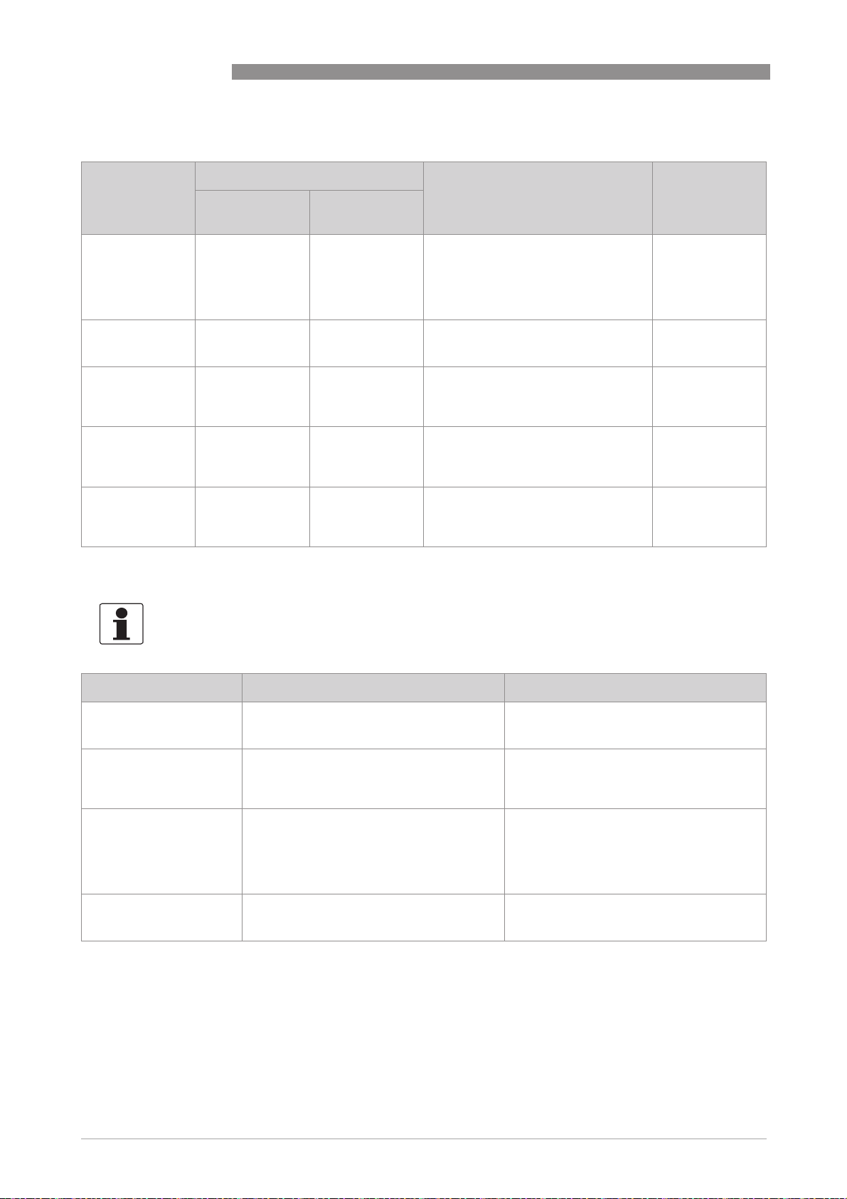
5 OPERATION
OPTISYS SLM 2100
Explanation of the error categories
Letter on display Error category according to: Description Action
NE64 VDI/VDE 2650
and NE107
Bold "FFFF" Failure Device failure Whole device or single component(s)
F (not bold) - Application
failure
S - Out of
specification
C Check request Passivated Either the device is outside operation
I - - Information, current measurement is
defective, replacement necessary,
measured values are not valid; mA
output ≤ 3.6 mA or set fault current
(depending on the seriousness of the
fault).
No internal error, but application
error has occurred; device okay, but
measurement not possible.
Measurement out of specification;
measurement continues, but
measured values only restrictedly
usable.
(standby, measured value is fixed or
specified), or the output values are
partially simulated or fixed.
okay and values unrestrictedly valid.
5.8.1 Error category "Device failure" (bold "F")
INFORMATION!
Regard that in case of an error message of the category "FFFF" the measured values are not valid!
Repair or
replacement
necessary!
Application test
or operator action
necessary!
Maintenance and
an accurate
check required!
Maintenance
required.
Depends on error
message, see
table in relevant
section.
Messages on the display Description Actions
FFFF motor blocked The motor has been blocked three times. Check if sensor and cable can be freely
FFFF sensor comm error Communication to sensor is permanently
interrupted.
FFFF limit switch error Indicating a failure of the sensor limit
switch.
FFFF sensor calibration Zero calibration was performed with higher
turbidity than used for the calibration of the
concentration.
moved, if so reset error manually and
restart measuring cycle.
Check if pick up axle board is correctly
seated and the optical path is clean. Error
needs to be reset manually and
measurement can be started again.
Check if the sensor can move up and down
by using the manual mode. If the sensor
does not reel down open the cable drum
compartment and look if the cable is reeled
up correctly. If the sensor is blocked, try to
pull it down carefully.
Repeat calibration in correct order again
60
www.krohne.com 03/2014 - 4002737302 - MA OPTISYS SLM 2100 R02 en
Page 61

OPTISYS SLM 2100
5.8.2 Error category "Application error" ( "F", not bold)
INFORMATION!
Regard that also in case of an error message of the category "F" the measured values are not
valid!
Messages on the display Description Actions
OPERATION 5
F Door open The door of the cable drum compartment is
open.
F Sensor supply power Power supply out of range Check if pick up axle board is correctly
Close the door; if closed check interlock
switch; Error will be automatically reset, if
problem was solved.
seated and the optical path is clean. Error
needs to be reset manually and
measurement can be started again.
5.8.3 Error category "Information" (I)
Messages on the display Description Actions
I Search reference point Sensor returns to home position to set zero
point of level measurement.
I Motor up Motor reels up.
I Motor down Motor reels down.
I Heater active Internal heater is switched on.
I Fan active Fan is switched on.
I Concentration not found The sensor did not detect the concentration
set by the user during this measuring cycle.
I Cable cleaning active Cleaning unit is switched on.
I Sensor cleaning active Cleaning unit is switched on.
I Rake guard Rake guard switch is active
I Pump lead time Pump lead time for external pump is active
I Relay 1 active Indicating that relay 1 is active
I Relay 2 active Indicating that relay 2 is active
No action necessary!
5.8.4 Error category "Out of specification" (S)
INFORMATION!
Regard that in case of an error message of the category "S" the measured values are only
conditionally usable!
Messages on the display Description Actions
S Sensor comm. warning The communication to the sensor was
S Out of spec.
concentration
interrupted.
Current output out of range (valid in Profile /
tracking mode for current channel B,
proportional to the measured
concentration).
www.krohne.com03/2014 - 4002737302 - MA OPTISYS SLM 2100 R02 en
Warning, that communication to sensor was
interrupted for a short time. No action
necessary. Error will be automatically reset,
if error does not occur again.
Check the limits of the 4…20 mA current
outputs. If the maximum concentration is
exceeded please enter a larger value.
61
Page 62

6 SERVICE
6.1 Manual initiation of a measurement
For service or maintenance you can manually initiate a measurement:
• Press ↓ on the Keypad for five seconds.
i The meter starts with a measurement cycle as soon as possible: the sensor goes down to
the defined maximum depth and returns to its start position, afterwards the meter works in
the normal mode.
6.2 Maintenance
INFORMATION!
For standard applications we recommend the following schedule.
Maintenance schedule .
Maintenance action Once a month Once every six months Once a year
OPTISYS SLM 2100
Visual check of sensor
and clean if necessary.
Visual check of lenses
and clean if necessary
Visual check of cable
and drum
Cleaning or
replacement of air filter
Check of screws and
nuts
Sensor check in water - - X
X X X
X X X
- X X
- - X
- - X
Maintenance
DANGER!
All work on the electrical connections may only be carried out with the power disconnected. Take
note of the voltage data on the nameplate!
INFORMATION!
During work on the device above the basin the personnel have to be protected by personal safety
equipment.
Drive the Sensor in the start position by changing the measurement function to "manual
operation". More information refer to
Menu C, setup
on page 46.
62
Visual check and cleaning of sensor
Check the sensor for any buildup, i.e. a large amount of dirt. If necessary, clean it with a damp
soft cloth or a soft brush.
Visual check and cleaning of lens
Check the lens for any buildup or film. If necessary, clean it with a suitable agent like water or
isopropyl alcohol and a soft rag or a soft brush.
www.krohne.com 03/2014 - 4002737302 - MA OPTISYS SLM 2100 R02 en
Page 63

OPTISYS SLM 2100
Check of screws and nuts
Check if all screws of the reeling unit as well as on the mounting frame are properly tight and
secured.
Sensor check in water
Check the sensor by immersion in water; this should give a low measuring value or even a "0" on
the converter display. By placing something solid (e.g. your finger) in the gap between the LED
and the sensor you should get a measuring value of 3000...9999 (depending on the calibration).
DANGER!
The surface in the both compartments becomes hot during operation and can cause burns. Wait,
after switching off the device until the surfaces have been cooled down.
DANGER!
Shut down the instrument by use of the external main switch if opening the compartment doors
or maintenance of moving parts.
Visual check of cable and drum
Check the cable, it must not have any damages or wear and has to be spooled correctly on the
drum. Always replace the cable if it shows any damage or severe wear of the insulation!
SERVICE 6
If the cable is not correctly spooled up or shows a large amount of dirt, lower the sensor
manually to the maximum position at first. During back hauling monitor the correct guidance of
the cable and that it spools up properly, clean it with a soft cloth if necessary.
Cleaning of the optical interface
WARNING!
Open and close the pick-up arm carefully to prevent the hazard of squashing and bruising.
Follow the steps for the maintenance of the optical interface.
1. Open the cable compartment door.
2. Pull the pick-up arm back and hold it.
3. Clean the optical interface with damp soft cloth with isopropyl alcohol.
4. Close the pick-up arm carefully and make sure that the connection is closed.
5. Close the cable compartment door.
www.krohne.com03/2014 - 4002737302 - MA OPTISYS SLM 2100 R02 en
63
Page 64

6 SERVICE
Cleaning or replacement of air filter
DANGER!
If the air filter is blocked the meter can catch fire which could result in health and safety hazards
or damage of the plant equipment.
WARNING!
Turn off the device during maintenance of the fan and fan filter.
1. Loosen the 2 nuts in the ventilation shaft.
2. Remove the ventilation shaft by pulling it up.
3. Remove the cover of the fan.
4. Clean or replace the air filter.
For assembling the ventilation please repeat the steps above in reverse order.
6.2.1 Cleaning unit (optional)
OPTISYS SLM 2100
The cleaning unit is an optional feature, nevertheless is it part of the standard menu to allow an
easy upgrade of the standard OPTISYS SLM 2100.
The sensor cleaning feature will be active either time based or cycle based. The cycle based
mode is only valid when the device is operating in level or profile measuring mode. In zone
tracking mode cleaning can be controlled only time based.
A measurement cycle is finished when the sensor reaches the bottom position in profile mode or
the position of the sludge level to search in level mode.
The sensor cleaning is a two phase process, in the bottom position the cleaning is enabled and
the sensor is moved back to the garage for cable cleaning. When the sensor has reached the
upper position the sensor cleaning phase starts and the sensor is moved through the cleaning
head in the garage. The number of passes is selectable in the cleaning menu.
Select the cleaning activation type in the menu first. In case of the activation mode is set to
"timer interval" the sensor cleaning is periodically performed when the selected time interval
has elapsed. By setting the cleaning activation mode to "counter interval" the sensor cleaning is
performed each time the selected number of measurement cycles has been conducted. Note
that the zone tracking measuring mode is not cycle based, in this mode for proper operation of
the sensor cleaning select the time based activation mode.
If an external water pump is connected to the device then the menu item "pump lead time" can
be used to delay the sensor cleaning process until pump system pressure has been setup. The
value of the pump lead time can remain at 0 seconds when no external water pump is in use.
64
The menu item "cleaning cycle" is defining the number of passes of the sensor through the
cleaning head. An external water pump can be controlled by the OPTISYS SLM 2100 when it is
enabled in the menu item external pump. Each cleaning cycle the external pump is switched on
when the water valve will be activated. Note that when the cleaning sequence is finished the
water valve remains open for 1 minute to empty cleaning system for protecting the system
against freezing at low temperatures.
www.krohne.com 03/2014 - 4002737302 - MA OPTISYS SLM 2100 R02 en
Page 65

OPTISYS SLM 2100
6.3 Spare parts availability
The manufacturer adheres to the basic principle that functionally adequate spare parts for each
device or each important accessory part will be kept available for a period of 3 years after
delivery of the last production run for the device.
This regulation only applies to spare parts which are subject to wear and tear under normal
operating conditions.
6.4 Availability of services
The manufacturer offers a range of services to support the customer after expiration of the
warranty. These include repair, maintenance, technical support and training.
INFORMATION!
For more precise information, please contact your local sales office.
6.5 Returning the device to the manufacturer
SERVICE 6
6.5.1 General information
This device has been carefully manufactured and tested. If installed and operated in accordance
with these operating instructions, it will rarely present any problems.
CAUTION!
Should you nevertheless need to return a device for inspection or repair, please pay strict
attention to the following points:
•
Due to statutory regulations on environmental protection and safeguarding the health and
safety of our personnel, manufacturer may only handle, test and repair returned devices that
have been in contact with products without risk to personnel and environment.
•
This means that the manufacturer can only service this device if it is accompanied by the
following certificate (see next section) confirming that the device is safe to handle.
CAUTION!
If the device has been operated with toxic, caustic, flammable or water-endangering products,
you are kindly requested:
•
to check and ensure, if necessary by rinsing or neutralising, that all cavities are free from
such dangerous substances,
•
to enclose a certificate with the device confirming that is safe to handle and stating the
product used.
www.krohne.com03/2014 - 4002737302 - MA OPTISYS SLM 2100 R02 en
65
Page 66

6 SERVICE
6.5.2 Form (for copying) to accompany a returned device
Company: Address:
Department: Name:
Tel. no.: Fax no.:
Manufacturer's order no. or serial no.:
The device has been operated with the following medium:
OPTISYS SLM 2100
This medium is: water-hazardous
toxic
caustic
flammable
We checked that all cavities in the device are free from such
substances.
We have flushed out and neutralized all cavities in the
device.
We hereby confirm that there is no risk to persons or the environment through any residual media
contained in the device when it is returned.
Date: Signature:
Stamp:
6.6 Disposal
CAUTION!
Disposal must be carried out in accordance with legislation applicable in your country.
66
www.krohne.com 03/2014 - 4002737302 - MA OPTISYS SLM 2100 R02 en
Page 67

OPTISYS SLM 2100
7.1 Measuring principle
The meter is using an optical sensor which travels through the media. Thus it can directly
measure the suspended solids concentration at different heights. The measurement of the
suspended solids content is based on the method of the transmission of light, which provides
precise measurement results independent of the sludge colour. The direct measuring principle
excludes incorrect measurements due to echo returns from walls or separating zones as well as
signal damping by fluff or floating sludge.
TECHNICAL DATA 7
Figure 7-1: Measuring principle
www.krohne.com03/2014 - 4002737302 - MA OPTISYS SLM 2100 R02 en
67
Page 68

7 TECHNICAL DATA
7.2 Technical data
INFORMATION!
•
The following data is provided for general applications. If you require data that is more
relevant to your specific application, please contact us or your local sales office.
•
Additional information (certificates, special tools, software,...) and complete product
documentation can be downloaded free of charge from the website (Download Center).
Measuring system
Measuring principle Level measurement via immersion of optical sensor with straight
Application range Level measurement of sludge blanket, fluff zone and zone tracking in
Design
Measuring range 0.1...30 g/l (depending on sludge type)
Units Concentration mg/l or g/l
Height / depth m, cm, feet, inch
Lowering speed sensor maximal 7.75 cm / 3.05" per second at 50 Hz
Internal heating "Off" above 8°C / 46.4°F, full power below 4°C/ 39.2°F.
Water connection of the cleaning
unit (optional)
OPTISYS SLM 2100
light transmission of NIR-light for suspended solids measurement.
clarifiers, sedimentation basins as well as in thickeners of water and
wastewater treatment plants.
Full cycle time for 10 m / 32.8 ft: 3 min
3/4" connector with metric thread (max. pressure 6 bar / 87 psi)
Display and user interface
Graphic display LCD display, backlit 128 x 64 pixels, temperature below -25°C / -13°F
Operating elements 4 push buttons for operator control of the signal converter without
Operating menu The operation menu consists of the measuring mode and the menu
Measuring mode 2 pages - measuring page with measuring results and status page
Menu mode variety of main and submenus that allows to customise the device
Operating and display languages English and German
may affect the readability of the display
opening the housing
mode
with status messages
68
www.krohne.com 03/2014 - 4002737302 - MA OPTISYS SLM 2100 R02 en
Page 69

OPTISYS SLM 2100
Measuring accuracy
Maximum measuring error
(concentration)
Maximum measuring error
(level)
Operating conditions
Altitude ≤ 2000 m / 6561.68 ft
Temperatures and pressure
Ambient temperature (in
operation)
Process temperature (sensor) 0...+60°C / +32...+140°F
Storage temperature 0...+60°C / +32...+140°F
Humidity Max. 90% at 40°C / 104°F
Max. immersion depth 10 m / 32.8 ft
Max. water pressure (process) 10 bar / 145 psi
Protection category IP 68 (sensor), IP 54 (electronic compartment) and IP 44 (cable drum
TECHNICAL DATA 7
5% full scale
1% full scale
-20...+50°C / -4...+122°F
compartment)
Installation conditions
Installation position Fixing on a handrail at open channels, basins or tanks.
Dimensions & weights For detailed information refer to
Dimensions
on page 72.
Materials
Enclosures Stainless steel 1.4301
Sensor Enclosures: Stainless steel 1.4404
Optical windows: Sapphire
Cable gland: POM
O-Ring: NBR
Sensor cable PUR
Electrical connections
Power supply (voltage) 230 VAC (-15% / +10%) at 50 Hz (±10%)
Power consumption 100 VA
Power rating 150 VA (maximum)
Internal fuse 1.6 A slow blow
Cable feedthrough M20x1.5 PA 6-12 mm
External fuse
(recommended)
Protection class I
Overvoltage catergory II
6 A
www.krohne.com03/2014 - 4002737302 - MA OPTISYS SLM 2100 R02 en
69
Page 70

7 TECHNICAL DATA
Inputs and outputs
General All in and outputs are electrically isolated from the power supply.
Inputs Control inputs: Three active
Outputs Current outputs Two outputs (4...20mA), galvanic
Relays Operating modes Relay 1 and 2: limit switch or
OPTISYS SLM 2100
U
= 8 VDC
control inputs, not polarity
sensitive
Operating modes Control input 1: Rake guard
Output data Current output A: level of fluff
Operating data U
Operating data for all relays U
out
= -10 mA
I
out
U
= <2 V
low
min I
U
high
max I
at 2 V = -8.7 mA
typical
= >4 V
at 4 V = -6.8 mA
typical
switch or external trigger
(switchable via Software)
Control input 2: Rake guard
switch or external trigger
(switchable via Software)
Control input 3: Maintenance
mode
isolated from power supply,
active mode
Current output B: level of sludge
blanket or concentration (profile)
= 18 VDC
max
I = 4...20 mA
I
≤ 22 mA
max
RL ≤ 550 Ω
status output
Relay 3: pump protection
≤ 24 VDC/250VAC
ext
I ≤0.3 A
70
www.krohne.com 03/2014 - 4002737302 - MA OPTISYS SLM 2100 R02 en
Page 71

OPTISYS SLM 2100
Approvals and certifications
CE The device fulfils the statutory requirements of the EC directives.
EMC Electromagnetic compatibility (EMC) in accordance with Directive
Low voltage directive Low voltage directive according to directive 206/95/EC
Directive for machinery Directive for machinery 2006/42/EC in accordance with:
RoHS Directive on the restriction of the use of certain hazardous
TECHNICAL DATA 7
The manufacturer certifies that these requirements have been met
by applying the CE marking.
2004/108/EC:
• EN 61000-6-4 2007 Electromagnetic compatibility (EMC) - Part 6-4:
Generic standards - Emission standard for industrial environments
• EN 61000-6-3:2007 Electromagnetic compatibility (EMC) - Part 6-3:
Generic standards - Emission standard for residential, commercial
and light-industrial environments
• EN 61000-6-2:2005 Electromagnetic compatibility (EMC) - Part 6-2:
Generic standards - Immunity for industrial environments
• EN 61326-1:2013 Electrical equipment for measurement, control
and laboratory use - EMC requirements - Part 1: General
requirements
• EN 61010-1:2011 Safety requirements for electrical equipment for
measurement, control, and laboratory use (Part 1: General
requirements)
• EN 60204-1:2006 Safety of machinery - Electrical equipment of
machines (Part 1: General requirements)
• EN 953:1997+A1:2009 Safety of machinery - Guards - General
requirements for the design and construction of fixed and movable
guards
substances in electrical and electronic equipment in accordance with
directive 2011/65/EU
www.krohne.com03/2014 - 4002737302 - MA OPTISYS SLM 2100 R02 en
71
Page 72

7 TECHNICAL DATA
7.3 Dimensions
OPTISYS SLM 2100
Figure 7-2: Dimensions
Dimensions [cm] Dimensions ["] Weight
[kg] [lbs]
a 460 18.11 26.5 58.42
b 420 16.54
c 188.55 7.1
d 512 20.16
e 81 3.19
f 260 10.24
g 550 21.65
h Ø 85 3.35
j Ø 40 1.57
k 231.5 9.11
72
www.krohne.com 03/2014 - 4002737302 - MA OPTISYS SLM 2100 R02 en
Page 73

OPTISYS SLM 2100
NOTES 8
www.krohne.com03/2014 - 4002737302 - MA OPTISYS SLM 2100 R02 en
73
Page 74

8 NOTES
OPTISYS SLM 2100
74
www.krohne.com 03/2014 - 4002737302 - MA OPTISYS SLM 2100 R02 en
Page 75

OPTISYS SLM 2100
NOTES 8
www.krohne.com03/2014 - 4002737302 - MA OPTISYS SLM 2100 R02 en
75
Page 76

KROHNE product overview
• Electromagnetic flowmeters
• Variable area flowmeters
• Ultrasonic flowmeters
• Mass flowmeters
• Vortex flowmeters
• Flow controllers
• Level meters
• Temperature assemblies
• Pressure transmitters
• Analysis products
• Products and systems for the oil & gas industry
• Measuring systems for the marine industry
Head Office KROHNE Messtechnik GmbH
Ludwig-Krohne-Str. 5
47058 Duisburg (Germany)
Tel.:+49 203 301 0
Fax:+49 203 301 103 89
info@krohne.com
The current list of all KROHNE contacts and addresses can be found at:
© KROHNE 03/2014 - 4002737302 - MA OPTISYS SLM 2100 R02 en - Subject to change without notice.
www.krohne.com
 Loading...