

Page 1
Handbook
Handbook
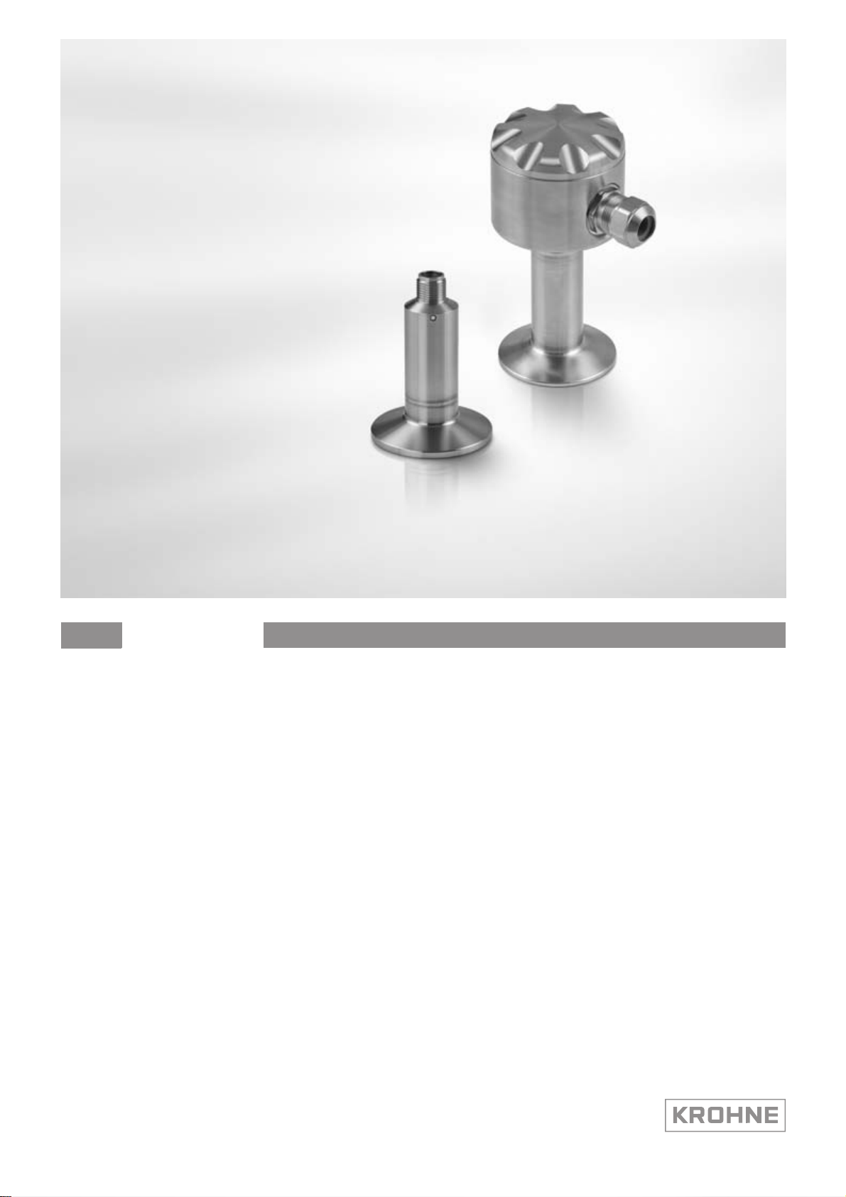
PTD 600
PTD 600
PTD 600PTD 600
Piezoresistive pressure transmitter with flush
membrane
HandbookHandbook
© KROHNE 03/2012 - 4001946801 - MA PTD 600 R01 en
Page 2

: IMPRINT :::::::::::::::::::::::::::::::::::::::
All rights reserved. It is prohibited to reproduce this documentation, or any part thereof, without
the prior written authorisation of KROHNE Messtechnik GmbH.
Subject to change without notice.
Copyright 2012 by
KROHNE Messtechnik GmbH - Ludwig-Krohne-Str. 5 - 47058 Duisburg (Germany)
2
www.krohne.com 03/2012 - 4001946801 - MA PTD 600 R01 en
Page 3

PTD 600
CONTENTS
1 Safety instructions 5
1.1 Intended use ..................................................................................................................... 5
1.2 Safety instructions from the manufacturer ..................................................................... 5
1.2.1 Copyright and data protection ................................................................................................ 5
1.2.2 Disclaimer ............................................................................................................................... 6
1.2.3 Product liability and warranty ................................................................................................ 6
1.2.4 Information concerning the documentation........................................................................... 6
1.2.5 Warnings and symbols used................................................................................................... 7
1.3 Safety instructions for the operator................................................................................. 7
2 Device description 8
2.1 Scope of delivery............................................................................................................... 8
2.2 Nameplate ........................................................................................................................ 8
3 Installation 9
3.1 Notes on installation ........................................................................................................ 9
3.2 Installation specifications ................................................................................................9
3.3 Mounting to pressure system .......................................................................................... 9
3.4 Hygiene ........................................................................................................................... 10
4 Electrical connections 11
4.1 Safety instructions.......................................................................................................... 11
4.2 Terminal assignment ..................................................................................................... 11
4.3 Electrical connection diagram ....................................................................................... 12
5 Operation 13
5.1 Start-up........................................................................................................................... 13
5.2 Configuration tool........................................................................................................... 13
6 Service 14
6.1 Spare parts availability...................................................................................................14
6.2 Availability of services .................................................................................................... 14
6.3 Repairs............................................................................................................................ 14
6.4 Accessories..................................................................................................................... 14
6.5 Returning the device to the manufacturer..................................................................... 15
6.5.1 General information.............................................................................................................. 15
6.5.2 Form (for copying) to accompany a returned device............................................................ 16
6.6 Disposal .......................................................................................................................... 16
www.krohne.com03/2012 - 4001946801 - MA PTD 600 R01 en
3
Page 4

CONTENTS
PTD 600
7 Technical data 17
7.1 Technical data................................................................................................................. 17
7.2 Dimensions and weights ................................................................................................ 19
7.3 Pressure resistance ....................................................................................................... 21
8 Notes 22
4
www.krohne.com 03/2012 - 4001946801 - MA PTD 600 R01 en
Page 5

PTD 600
1.1 Intended use
CAUTION!
Responsibility for the use of the measuring devices with regard to suitability, intended use and
corrosion resistance of the used materials against the measured fluid lies solely with the
operator.
INFORMATION!
The manufacturer is not liable for any damage resulting from improper use or use for other than
the intended purpose.
The PTD 600
PTD 600 pressure transmitter is designed to measure the absolute pressure and gauge
PTD 600PTD 600
pressure of gases, vapours and liquids. As an option, it can also measure the hydrostatic level.
1.2 Safety instructions from the manufacturer
1.2.1 Copyright and data protection
The contents of this document have been created with great care. Nevertheless, we provide no
guarantee that the contents are correct, complete or up-to-date.
SAFETY INSTRUCTIONS 1
The contents and works in this document are subject to copyright. Contributions from third
parties are identified as such. Reproduction, processing, dissemination and any type of use
beyond what is permitted under copyright requires written authorisation from the respective
author and/or the manufacturer.
The manufacturer tries always to observe the copyrights of others, and to draw on works created
in-house or works in the public domain.
The collection of personal data (such as names, street addresses or e-mail addresses) in the
manufacturer's documents is always on a voluntary basis whenever possible. Whenever
feasible, it is always possible to make use of the offerings and services without providing any
personal data.
We draw your attention to the fact that data transmission over the Internet (e.g. when
communicating by e-mail) may involve gaps in security. It is not possible to protect such data
completely against access by third parties.
We hereby expressly prohibit the use of the contact data published as part of our duty to publish
an imprint for the purpose of sending us any advertising or informational materials that we have
not expressly requested.
www.krohne.com03/2012 - 4001946801 - MA PTD 600 R01 en
5
Page 6

1 SAFETY INSTRUCTIONS
1.2.2 Disclaimer
The manufacturer will not be liable for any damage of any kind by using its product, including,
but not limited to direct, indirect or incidental and consequential damages.
This disclaimer does not apply in case the manufacturer has acted on purpose or with gross
negligence. In the event any applicable law does not allow such limitations on implied warranties
or the exclusion of limitation of certain damages, you may, if such law applies to you, not be
subject to some or all of the above disclaimer, exclusions or limitations.
Any product purchased from the manufacturer is warranted in accordance with the relevant
product documentation and our Terms and Conditions of Sale.
The manufacturer reserves the right to alter the content of its documents, including this
disclaimer in any way, at any time, for any reason, without prior notification, and will not be liable
in any way for possible consequences of such changes.
1.2.3 Product liability and warranty
The operator shall bear responsibility for the suitability of the device for the specific purpose.
The manufacturer accepts no liability for the consequences of misuse by the operator. Improper
installation and operation of the devices (systems) will cause the warranty to be void. The
respective "Standard Terms and Conditions" which form the basis for the sales contract shall
also apply.
PTD 600
1.2.4 Information concerning the documentation
To prevent any injury to the user or damage to the device it is essential that you read the
information in this document and observe applicable national standards, safety requirements
and accident prevention regulations.
If this document is not in your native language and if you have any problems understanding the
text, we advise you to contact your local office for assistance. The manufacturer can not accept
responsibility for any damage or injury caused by misunderstanding of the information in this
document.
This document is provided to help you establish operating conditions, which will permit safe and
efficient use of this device. Special considerations and precautions are also described in the
document, which appear in the form of underneath icons.
6
www.krohne.com 03/2012 - 4001946801 - MA PTD 600 R01 en
Page 7
PTD 600
1.2.5 Warnings and symbols used
Safety warnings are indicated by the following symbols.
DANGER!
This information refers to the immediate danger when working with electricity.
DANGER!
This warning refers to the immediate danger of burns caused by heat or hot surfaces.
DANGER!
This warning refers to the immediate danger when using this device in a hazardous atmosphere.
DANGER!
These warnings must be observed without fail. Even partial disregard of this warning can lead to
serious health problems and even death. There is also the risk of seriously damaging the device
or parts of the operator's plant.
SAFETY INSTRUCTIONS 1
WARNING!
Disregarding this safety warning, even if only in part, poses the risk of serious health problems.
There is also the risk of damaging the device or parts of the operator's plant.
CAUTION!
Disregarding these instructions can result in damage to the device or to parts of the operator's
plant.
INFORMATION!
These instructions contain important information for the handling of the device.
LEGAL NOTICE!
This note contains information on statutory directives and standards.
• HANDLING
HANDLING
HANDLINGHANDLING
This symbol designates all instructions for actions to be carried out by the operator in the
specified sequence.
i RESULT
RESULT
RESULTRESULT
This symbol refers to all important consequences of the previous actions.
1.3 Safety instructions for the operator
WARNING!
In general, devices from the manufacturer may only be installed, commissioned, operated and
maintained by properly trained and authorized personnel.
This document is provided to help you establish operating conditions, which will permit safe and
efficient use of this device.
www.krohne.com03/2012 - 4001946801 - MA PTD 600 R01 en
7
Page 8

2 DEVICE DESCRIPTION
2.1 Scope of delivery
The following items are supplied with the device:
• Measuring device in ordered version
• Product documentation
2.2 Nameplate
INFORMATION!
Look at the device nameplate to ensure that the device is delivered according to your order.
Check for the correct supply voltage printed on the nameplate.
The important technical values are engraved on the device body.
PTD 600
Figure 2-1: Example of engraved values on the nameplate
1 Manufacturer
2 Device designation and order code
3 Supply voltage
4 Output signal
5 Measuring range
6 Temperature range
7 Serial number
8
www.krohne.com 03/2012 - 4001946801 - MA PTD 600 R01 en
Page 9

PTD 600
3.1 Notes on installation
INFORMATION!
Inspect the cartons carefully for damages or signs of rough handling. Report damage to the
carrier and to the local office of the manufacturer.
INFORMATION!
Do a check of the packing list to make sure that you have all the elements given in the order.
INFORMATION!
Look at the device nameplate to ensure that the device is delivered according to your order.
Check for the correct supply voltage printed on the nameplate.
3.2 Installation specifications
Even though its design is robust, the pressure transmitter should not be exposed to any heavy
impact. Avoid high static and dynamic pressures that exceed the values indicated in "Technical
data".
INSTALLATION 3
In the case of flush connections, there is one wavy, highly sensitive membrane exposed. To avoid
damaging the membrane, do not use abrasive cleaning agents or allow it to come into contact
with hard bodies (including fingers) or tools. The protective cover should thus only be removed
immediately before installing the transmitter.
3.3 Mounting to pressure system
Versions with thread connection
Versions with thread connection
Versions with thread connectionVersions with thread connection
• The pressure transmitter features a male thread for the connection.
• If the seal is metallic, it is recommended to grease the raised face with a MoS
based lubricant.
• Use a suitable wrench for mounting. Do not exceed the tightening torque when mounting
(refer to the table below).
Process
connection
G½ 10 15
G1 40
Versions with hygienic clamp connection
Versions with hygienic clamp connection
Versions with hygienic clamp connectionVersions with hygienic clamp connection
• The pressure transmitter features appropriate hygienic clamp connections for the
connection.
• Only use clamp connections designed for the specific application and pressure.
• Do not damage the seal during installation or replacement.
Tightening torques [Nm] at a pressure of
≤ 1bar/ 14.5psi 1 bar / 14.5 psi > p ≤40 bar / 580 psi
or Vaseline-
2
www.krohne.com03/2012 - 4001946801 - MA PTD 600 R01 en
9
Page 10

3 INSTALLATION
Versions with cooling neck
Versions with cooling neck
Versions with cooling neckVersions with cooling neck
To ensure proper cooling function, versions with cooling neck (T
installed at a maximum 10° angle to the horizontal.
3.4 Hygiene
• The mounting position, connection piece and sealing point should be designed so that the
system is completely self-draining and there are no hollow spaces.
• The transmitters are designed for CIP and SIP:
= 150°C / 302°F < 60 minutes for hygienic process connections;
T
max
T
= 125°C / 257°F for devices with thread connection
max
• It is not possible to sterilise the entire transmitter without protective devices in place.
Medium
PTD 600
≤ 200°C / 392°F) must be
10
www.krohne.com 03/2012 - 4001946801 - MA PTD 600 R01 en
Page 11

PTD 600
4.1 Safety instructions
DANGER!
All work on the electrical connections may only be carried out with the power disconnected. Take
note of the voltage data on the nameplate!
DANGER!
Observe the national regulations for electrical installations!
WARNING!
Observe without fail the local occupational health and safety regulations. Any work done on the
electrical components of the measuring device may only be carried out by properly trained
specialists.
INFORMATION!
Look at the device nameplate to ensure that the device is delivered according to your order.
Check for the correct supply voltage printed on the nameplate.
ELECTRICAL CONNECTIONS 4
4.2 Terminal assignment
Figure 4-1: Terminal assignment for 4-pin M12 plug
1 +V
(supply voltage)
S
2 I
/GND (current output)
Out
Figure 4-2: Terminal assignment for field housing
1 I
/GND (current output)
Out
2 +V
(supply voltage)
S
3 Shielding
4 Cable diameter: 8...10 mm / 0.3...0.4" (cable not included in delivery)
www.krohne.com03/2012 - 4001946801 - MA PTD 600 R01 en
11
Page 12

4 ELECTRICAL CONNECTIONS
4.3 Electrical connection diagram
DANGER!
•
Check polarity and use shielded cables.
•
The transmitter housing and shield must be grounded.
•
Place the shielding on the control side to ground across a large area to ensure the best
possible protection against electromagnetic interference.
For field housing versions, place the shield evenly on the contact surface of the cable
feedthrough.
•
Avoid potential differences between the transmitter housing and the control if at all possible.
To comply fully with PELV requirements in accordance with EN 60204-1
(ground) to a point in the system with protective earth.
PTD 600
§
6.4.1, connect 0 V
Figure 4-3: Electrical connection diagram
a: pressure transmitter
b: power supply / measuring unit
1 +V
(supply voltage)
S
2 I
/GND (current output)
Out
3 R
Load
4 Ground
5 Measurement
6 Operating voltage
12
www.krohne.com 03/2012 - 4001946801 - MA PTD 600 R01 en
Page 13

PTD 600
5.1 Start-up
Before connecting to power, please check that the system has been correctly installed.
This includes:
• The device must be mechanically safe and mounted in compliance with the regulations.
• Check the leak-tightness of the process connection.
• Make sure that the M12 plug is properly connected.
• The power connections must have been made in compliance with the regulations.
• Check that the electrical operating data of the power supply are correct.
• Switching on the power.
5.2 Configuration tool
The configuration tool (order number XGP9000010) can be ordered optionally to configure the
pressure transmitter.
OPERATION 5
Scope of delivery:
• Interface unit
• CD with software and product drivers (DTM)
• USB cable
• Cable with M12 connector
The configuration tool connects the transmitter to a computer. With the proper software, an
online connection to the pressure transmitter can be established.
When using this tool, device information including the serial number and measuring point
numbers are displayed on the computer. Settings including the zero point, measuring range,
signal limits and others can be configured.
There is also a reset function to return to the default values.
DANGER!
Disconnect the power supply before connecting the configuration tool to the transmitter!
www.krohne.com03/2012 - 4001946801 - MA PTD 600 R01 en
13
Page 14

6 SERVICE
6.1 Spare parts availability
The manufacturer adheres to the basic principle that functionally adequate spare parts for each
device or each important accessory part will be kept available for a period of 3 years after
delivery of the last production run for the device.
This regulation only applies to spare parts which are subject to wear and tear under normal
operating conditions.
6.2 Availability of services
The manufacturer offers a range of services to support the customer after expiration of the
warranty. These include repair, maintenance, technical support and training.
INFORMATION!
For more precise information, please contact your local representative.
6.3 Repairs
PTD 600
Repairs may be carried out exclusively by the manufacturer or the manufacturer authorised
specialist companies.
6.4 Accessories
Designation Type Order code
Welded sleeve HWN 500 VGP7 4001000
Varivent flange version N HVF 550 VGP7 400C000
Dairy pipe installation set DN50 HMM 550 VGP7 400B000
Tri-Clamp flange 2", DN50
DIN 32676
Tri-Clamp flange 1½", DN40
DIN 32676
Configuration tool - XGP 900010
INFORMATION!
Other hygienic connections are available on request.
HTC 500 VGP7 400D000
HTC 540 VGP7 400V000
14
www.krohne.com 03/2012 - 4001946801 - MA PTD 600 R01 en
Page 15

PTD 600
6.5 Returning the device to the manufacturer
6.5.1 General information
This device has been carefully manufactured and tested. If installed and operated in accordance
with these operating instructions, it will rarely present any problems.
CAUTION!
Should you nevertheless need to return a device for inspection or repair, please pay strict
attention to the following points:
•
Due to statutory regulations on environmental protection and safeguarding the health and
safety of our personnel, manufacturer may only handle, test and repair returned devices that
have been in contact with products without risk to personnel and environment.
•
This means that the manufacturer can only service this device if it is accompanied by the
following certificate (see next section) confirming that the device is safe to handle.
CAUTION!
If the device has been operated with toxic, caustic, flammable or water-endangering products,
you are kindly requested:
•
to check and ensure, if necessary by rinsing or neutralizing, that all cavities are free from
such dangerous substances,
•
to enclose a certificate with the device confirming that is safe to handle and stating the
product used.
SERVICE 6
www.krohne.com03/2012 - 4001946801 - MA PTD 600 R01 en
15
Page 16

6 SERVICE
6.5.2 Form (for copying) to accompany a returned device
Company: Address:
Department: Name:
Tel. no.: Fax no.:
Manufacturer's order no. or serial no.:
The device has been operated with the following medium:
PTD 600
This medium is: water-hazardous
toxic
caustic
flammable
We checked that all cavities in the device are free from such
substances.
We have flushed out and neutralized all cavities in the
device.
We hereby confirm that there is no risk to persons or the environment through any residual media
contained in the device when it is returned.
Date: Signature:
Stamp:
6.6 Disposal
CAUTION!
Disposal must be carried out in accordance with legislation applicable in your country.
16
www.krohne.com 03/2012 - 4001946801 - MA PTD 600 R01 en
Page 17

PTD 600
TECHNICAL DATA 7
7.1 Technical data
INFORMATION!
•
The following data is provided for general applications. If you require data that is more
relevant to your specific application, please contact us or your local representative.
•
Additional information (certificates, special tools, software,...) and complete product
documentation can be downloaded free of charge from the website (Download Center).
Measuring system
Measuring principle Piezoresistive silicon sensor
Application range Hydrostatic level detection as well as pressure measurement in
Measuring range -1...40 bar / -14.5...580 psi
Measuring accuracy
Reference conditions Medium: air
Pressure type Gauge pressure / absolute pressure
Measuring accuracy 0.5%, 0.25% or 0.1% of the full scale (including linearity, hysteresis
Deviation of zero point ≤±0.03% of the full scale/10 K
Deviation of span ≤±0.03% of the full scale/10 K
Long-term stability 0.1% of the full scale/ year
Response time (10...90%) 5ms
pipelines for gas, steam and liquids
Temperature: +20°C / +68°F
and repeatability)
Operating conditions
Temperature
Temperature
TemperatureTemperature
Process temperature Standard: -10…+125°C / +14...+257°F
With optional cooling neck: -10…+200°C / +14...+392°F
CIP/SIP Max. up to 150°C/ 302°F < 60 minutes for hygienic process
Ambient temperature -10…+85°C / +14...+185°F
Storage temperature -10…+85°C / +14...+185°F
Other conditions
Other conditions
Other conditionsOther conditions
Protection category acc. to IEC 529 / EN 60529 IP67
connections
Max. up to 125°C/ 257°F for devices with thread connection
Installation conditions
Installation Can be installed in any position, zero point or position correction may
Dimensions and weights For detailed information refer to section "Dimensions and weights".
be required following installation.
To ensure proper cooling function, versions with cooling neck
(T
to the horizontal.
≤ 200°C/ 392°F) must be installed at a maximum 10° angle
Medium
www.krohne.com03/2012 - 4001946801 - MA PTD 600 R01 en
17
Page 18

7 TECHNICAL DATA
PTD 600
Materials
Sensor housing
Process connection
Stainless steel 1.4404 / 316L or Hastelloy®C
Stainless steel 1.4404 / 316L or Hastelloy®C
Process connections
Standard G1 connection with flush hygienic cone in combination with hygienic
Optional G½ with flush hygienic cone
process connection adapters like the Tri-Clamp, 11851, Varivent (see
the "Accessories" data sheet for details)
DN40/DN50 clamp acc. to DIN 32676
38/51 mm clamp ISO 2852
1½" Tri-Clamp and GEA Tuchenhagen type N connection
Electrical connection
Power supply 8...30 VDC
Load resistance R
Output signal 4...20 mA
Insulation resistance >100 MΩ at 750 V
Cable feedthroughs Compact housing: M12 plug made of stainless steel (1.4404 / 316L)
[Ω] = (U
Load
Field housing: M16 made of stainless steel (1.4404 / 316L)
[V] - 8 V) / 20 [mA]
Supply
Approvals and certificates
CE The device fulfils the statutory requirements of the EC directives. The
Electromagnetic compatibility (EMC) 2004/108/EC in accordance with EN 61000-6-2 and EN 61000-6-3
Pressure equipment directive 97/23/EC
Other standards and approvals
Other standards and approvals
Other standards and approvalsOther standards and approvals
Vibration according to IEC 60068-2-6 1.5 mm (10...55 Hz), 10 g (58 Hz...2 KHz), 10 cycles within 2.5 h per
Shock test in accordance with IEC 60068-2-27 50 g/11 ms, 100 g/6 ms, 10 x pulse/axis and direction
Bump in accordance with IEC 60068-2-29 100 g/2 ms, 4000 x pulse/axis and direction
Statistical failures in accordance with
IEC 60068-2-64
Hygiene FDA approved materials
manufacturer certifies that these requirements have been met by
applying the CE marking.
axis
0.1 g2/Hz (20 Hz...1 KHz), 30 min. per axis (>10 g RMS)
18
www.krohne.com 03/2012 - 4001946801 - MA PTD 600 R01 en
Page 19

PTD 600
7.2 Dimensions and weights
Hygienic process connections
TECHNICAL DATA 7
Figure 7-1: Dimensions for pressure transmitter with hygienic connections
1 Compact housing with M12 plug
2 Field housing with M16 cable feedthroughs
3 Max. cable diameter: Ø8...10 mm / Ø0.3...0.4"
4 DN38 ISO 2852 / Tri-Clamp 1½", DN38 DIN 32676 clamp 3A
5 DN51 ISO 2852 / DIN 32676 clamp 3A
6 GEA Tuchenhagen type N connection
Dimensions
1 2 4 5 6
[mm] ["] [mm] ["] [mm] ["] [mm] ["] [mm] ["]
a 51.6 2 94.5 3.7 - - - - - -
b Ø22 Ø0.9 Ø22 Ø0.9 - - - - - -
c - - - - Ø50.5 Ø2 Ø64 Ø2.5 Ø84 Ø3.3
d - - - - 17.3 0.7 17.3 0.7 - -
e - - - - - - - - Ø68 Ø2.7
Weight for compact housing: approx. 150 g / 0.33 lbs
Weight field housing: approx. 600 g / 1.32 lbs
www.krohne.com03/2012 - 4001946801 - MA PTD 600 R01 en
19
Page 20

7 TECHNICAL DATA
Thread with flush hygienic cone
PTD 600
Figure 7-2: Dimensions for pressure transmitter with thread and flush hygienic cone
1 Compact housing with M12 plug
2 Field housing with M16 cable feedthrough
3 Max. cable diameter: Ø8...10 mm / Ø0.3...0.4"
4 G½
5 G1
Dimensions
1 2 4 5
[mm] ["] [mm] ["] [mm] ["] [mm] ["]
a 51.6 2 94.5 3.7 - - - -
b Ø22 Ø0.9 Ø22 Ø0.9 - - - -
c - - - - 39 1.5 51 2
d - - - - 22.3 0.9 27 1.1
e - - - - 9 - - -
f - - - - Ø15.5 Ø0.6 Ø25.5 Ø1
g - - - - G½ G1
Weight compact housing: approx. 130 g / 0.29 lbs
Weight field housing: approx. 570 g / 1.26 lbs
20
INFORMATION!
All thread connections can be made into hygienic versions by using the hygienic process
connection adapters. See the "Accessories" data sheet for details.
www.krohne.com 03/2012 - 4001946801 - MA PTD 600 R01 en
Page 21

PTD 600
7.3 Pressure resistance
Pressure range -0.1...0.1 -0.2...+0.2 0...1 0...1.6 0...6 0...25 0...40
Over pressure 1 3 3 15 60 70 135
Burst pressure 2 6 6 30 120 140 270
TECHNICAL DATA 7
Pressure in bar
0...0.1 0...0.4 -1...0 0...2 0...10 0...20 -1...39
0...0.16 0...0.6 -1...0.6 0...2.5 -1...9 -1...24
0...0.25 -1...1.5 0...16
0...4 -1...15
-1...3
-1...5
www.krohne.com03/2012 - 4001946801 - MA PTD 600 R01 en
21
Page 22

8 NOTES
PTD 600
22
www.krohne.com 03/2012 - 4001946801 - MA PTD 600 R01 en
Page 23

PTD 600
NOTES 8
www.krohne.com03/2012 - 4001946801 - MA PTD 600 R01 en
23
Page 24

KROHNE product overview
• Electromagnetic flowmeters
• Variable area flowmeters
• Ultrasonic flowmeters
• Mass flowmeters
• Vortex flowmeters
• Flow controllers
• Level meters
• Temperature meters
• Pressure meters
• Analysis products
• Products and systems for the oil & gas industry
• Measuring systems for the marine industry
Head Office KROHNE Messtechnik GmbH
Ludwig-Krohne-Str. 5
47058 Duisburg (Germany)
Tel.:+49 (0)203 301 0
Fax:+49 (0)203 301 10389
info@krohne.de
© KROHNE 03/2012 - 4001946801 - MA PTD 600 R01 en - Subject to change without notice.
The current list of all KROHNE contacts and addresses can be found at:
www.krohne.com
 Loading...