

Page 1
OPTISENS PH 9100
Handbook
pH sensor
The documentation is only complete when used in combination with the relevant
documentation for the signal converter.
© KROHNE 09/2012 - 4002314801 - MA OPTISENS PH 9100 R02 en
Page 2

: IMPRINT :::::::::::::::::::::::::::::::::::::::
All rights reserved. It is prohibited to reproduce this documentation, or any part thereof, without
the prior written authorisation of KROHNE Messtechnik GmbH.
Subject to change without notice.
Copyright 2012 by
KROHNE Messtechnik GmbH - Ludwig-Krohne-Str. 5 - 47058 Duisburg (Germany)
2
www.krohne.com 09/2012 - 4002314801 - MA OPTISENS PH 9100 R02 en
Page 3

OPTISENS PH 9100
CONTENTS
1 Safety instructions 5
1.1 Intended use ..................................................................................................................... 5
1.2 Safety instructions from the manufacturer ..................................................................... 5
1.2.1 Copyright and data protection ................................................................................................ 5
1.2.2 Disclaimer ............................................................................................................................... 6
1.2.3 Product liability and warranty ................................................................................................ 6
1.2.4 Information concerning the documentation........................................................................... 6
1.2.5 Warnings and symbols used................................................................................................... 7
1.3 Safety instructions for the operator................................................................................. 7
2 Device description 8
2.1 Scope of delivery............................................................................................................... 8
2.2 Device description ............................................................................................................ 9
2.2.1 pH sensor ................................................................................................................................9
2.3 Nameplate ...................................................................................................................... 10
3 Installation 11
3.1 Notes on installation ......................................................................................................11
3.2 Storage and transport .................................................................................................... 11
3.3 Installation procedure .................................................................................................... 12
3.4 Pre-installation requirements ....................................................................................... 13
3.5 Electrical connection......................................................................................................13
3.5.1 Connecting the sensor cable to the signal converter .......................................................... 14
3.5.2 Connecting the external temperature sensor...................................................................... 15
3.5.3 Connecting the cable to the sensor...................................................................................... 16
3.6 Calibrating the sensor.................................................................................................... 16
3.7 Installing the sensor....................................................................................................... 17
3.7.1 General installation instructions.......................................................................................... 17
3.7.2 Mounting to a flow-through holder ...................................................................................... 18
3.8 Installing an external temperature sensor.................................................................... 19
3.9 Examples of a typical measuring point.......................................................................... 20
4 Operation 21
4.1 Menu mode structure..................................................................................................... 21
4.2 Function tables ............................................................................................................... 23
4.2.1 Menu A, quick setup.............................................................................................................. 23
4.2.2 Menu B, test .......................................................................................................................... 24
4.2.3 Menu C, setup ....................................................................................................................... 25
4.3 Calibration ...................................................................................................................... 27
4.3.1 Temperature compensation .................................................................................................27
4.3.2 Calibrating pH measurement ...............................................................................................31
4.3.3 Calibration log....................................................................................................................... 36
4.4 Troubleshooting.............................................................................................................. 36
5 Service 37
www.krohne.com09/2012 - 4002314801 - MA OPTISENS PH 9100 R02 en
3
Page 4

CONTENTS
OPTISENS PH 9100
5.1 Maintenance ................................................................................................................... 37
5.1.1 Cleaning ................................................................................................................................ 37
5.1.2 Aging and re-calibration ....................................................................................................... 37
5.2 Spare parts availability...................................................................................................38
5.3 Availability of services .................................................................................................... 38
5.4 Returning the device to the manufacturer..................................................................... 38
5.4.1 General information.............................................................................................................. 38
5.4.2 Form (for copying) to accompany a returned device............................................................ 39
5.5 Disposal .......................................................................................................................... 39
6 Technical data 40
6.1 Measuring principle........................................................................................................40
6.1.1 pH measurement .................................................................................................................. 40
6.2 Technical data................................................................................................................. 42
6.3 Dimensions ..................................................................................................................... 44
7 Appendix 45
7.1 pH as a function of mV.................................................................................................... 45
7.2 pH temperature dependency.......................................................................................... 46
8 Notes 47
4
www.krohne.com 09/2012 - 4002314801 - MA OPTISENS PH 9100 R02 en
Page 5

OPTISENS PH 9100
1.1 Intended use
CAUTION!
Responsibility for the use of the measuring devices with regard to suitability, intended use and
corrosion resistance of the used materials against the measured fluid lies solely with the
operator.
INFORMATION!
The manufacturer is not liable for any damage resulting from improper use or use for other than
the intended purpose.
The intended use of OPTISENS PH 9100 sensor is the measurement of pH value in water
applications. The sensor is suitable for connection to the MAC 100 signal converter.
1.2 Safety instructions from the manufacturer
1.2.1 Copyright and data protection
The contents of this document have been created with great care. Nevertheless, we provide no
guarantee that the contents are correct, complete or up-to-date.
SAFETY INSTRUCTIONS 1
The contents and works in this document are subject to copyright. Contributions from third
parties are identified as such. Reproduction, processing, dissemination and any type of use
beyond what is permitted under copyright requires written authorisation from the respective
author and/or the manufacturer.
The manufacturer tries always to observe the copyrights of others, and to draw on works created
in-house or works in the public domain.
The collection of personal data (such as names, street addresses or e-mail addresses) in the
manufacturer's documents is always on a voluntary basis whenever possible. Whenever
feasible, it is always possible to make use of the offerings and services without providing any
personal data.
We draw your attention to the fact that data transmission over the Internet (e.g. when
communicating by e-mail) may involve gaps in security. It is not possible to protect such data
completely against access by third parties.
We hereby expressly prohibit the use of the contact data published as part of our duty to publish
an imprint for the purpose of sending us any advertising or informational materials that we have
not expressly requested.
www.krohne.com09/2012 - 4002314801 - MA OPTISENS PH 9100 R02 en
5
Page 6

1 SAFETY INSTRUCTIONS
1.2.2 Disclaimer
The manufacturer will not be liable for any damage of any kind by using its product, including,
but not limited to direct, indirect or incidental and consequential damages.
This disclaimer does not apply in case the manufacturer has acted on purpose or with gross
negligence. In the event any applicable law does not allow such limitations on implied warranties
or the exclusion of limitation of certain damages, you may, if such law applies to you, not be
subject to some or all of the above disclaimer, exclusions or limitations.
Any product purchased from the manufacturer is warranted in accordance with the relevant
product documentation and our Terms and Conditions of Sale.
The manufacturer reserves the right to alter the content of its documents, including this
disclaimer in any way, at any time, for any reason, without prior notification, and will not be liable
in any way for possible consequences of such changes.
1.2.3 Product liability and warranty
The operator shall bear responsibility for the suitability of the device for the specific purpose.
The manufacturer accepts no liability for the consequences of misuse by the operator. Improper
installation and operation of the devices (systems) will cause the warranty to be void. The
respective "Standard Terms and Conditions" which form the basis for the sales contract shall
also apply.
OPTISENS PH 9100
1.2.4 Information concerning the documentation
To prevent any injury to the user or damage to the device it is essential that you read the
information in this document and observe applicable national standards, safety requirements
and accident prevention regulations.
If this document is not in your native language and if you have any problems understanding the
text, we advise you to contact your local office for assistance. The manufacturer can not accept
responsibility for any damage or injury caused by misunderstanding of the information in this
document.
This document is provided to help you establish operating conditions, which will permit safe and
efficient use of this device. Special considerations and precautions are also described in the
document, which appear in the form of underneath icons.
6
www.krohne.com 09/2012 - 4002314801 - MA OPTISENS PH 9100 R02 en
Page 7
OPTISENS PH 9100
1.2.5 Warnings and symbols used
Safety warnings are indicated by the following symbols.
DANGER!
This information refers to the immediate danger when working with electricity.
DANGER!
This warning refers to the immediate danger of burns caused by heat or hot surfaces.
DANGER!
This warning refers to the immediate danger when using this device in a hazardous atmosphere.
DANGER!
These warnings must be observed without fail. Even partial disregard of this warning can lead to
serious health problems and even death. There is also the risk of seriously damaging the device
or parts of the operator's plant.
SAFETY INSTRUCTIONS 1
WARNING!
Disregarding this safety warning, even if only in part, poses the risk of serious health problems.
There is also the risk of damaging the device or parts of the operator's plant.
CAUTION!
Disregarding these instructions can result in damage to the device or to parts of the operator's
plant.
INFORMATION!
These instructions contain important information for the handling of the device.
LEGAL NOTICE!
This note contains information on statutory directives and standards.
• HANDLING
This symbol designates all instructions for actions to be carried out by the operator in the
specified sequence.
i RESULT
This symbol refers to all important consequences of the previous actions.
1.3 Safety instructions for the operator
WARNING!
In general, devices from the manufacturer may only be installed, commissioned, operated and
maintained by properly trained and authorized personnel.
This document is provided to help you establish operating conditions, which will permit safe and
efficient use of this device.
www.krohne.com09/2012 - 4002314801 - MA OPTISENS PH 9100 R02 en
7
Page 8
2 DEVICE DESCRIPTION
2.1 Scope of delivery
INFORMATION!
Inspect the cartons carefully for damages or signs of rough handling. Report damage to the
carrier and to the local office of the manufacturer.
INFORMATION!
Do a check of the packing list to make sure that you have all the elements given in the order.
INFORMATION!
Look at the device nameplate to ensure that the device is delivered according to your order.
Check for the correct supply voltage printed on the nameplate.
OPTISENS PH 9100
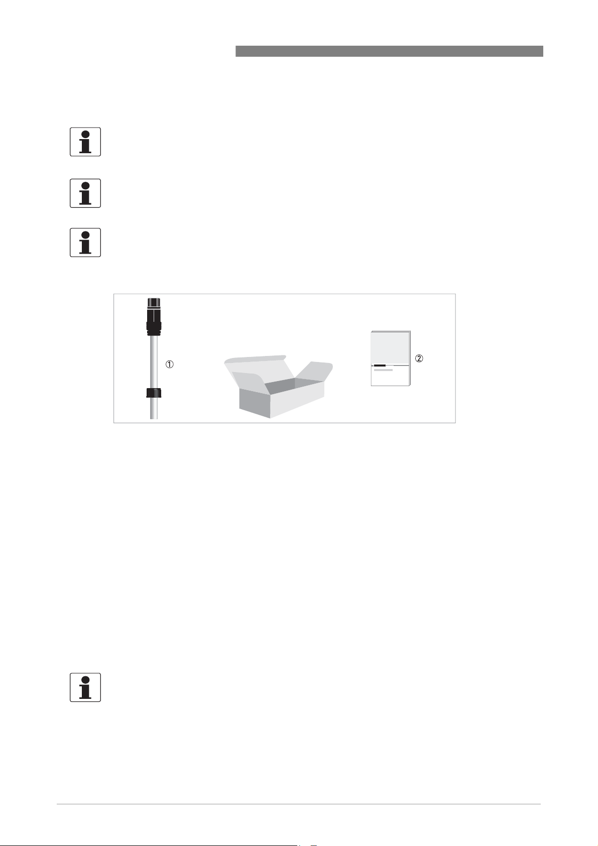
Figure 2-1: Standard scope of delivery
1 Ordered sensor
2 Documentation
Optional accessories
• SENSOFIT FLOW 1000 - flow-through holder
• SENSOFIT IMM 1000 - immersion holder
• SENSOFIT INS 1000 - insertion screw-in adapter
• PG 13.5 mounting kit
• KCl reservoir 50 ml
• Cable pH/ORP-W Sensor coax 5 m / 16.4 ft
• Cable pH/ORP-W Sensor coax 10 m / 32.8 ft
Consumables/Spare parts available
• OPTISENS PH 9100
• 250 ml pH buffer solutions pH4/pH7
INFORMATION!
For further Information contact your local sales office.
8
www.krohne.com 09/2012 - 4002314801 - MA OPTISENS PH 9100 R02 en
Page 9
OPTISENS PH 9100
2.2 Device description
2.2.1 pH sensor
DEVICE DESCRIPTION 2
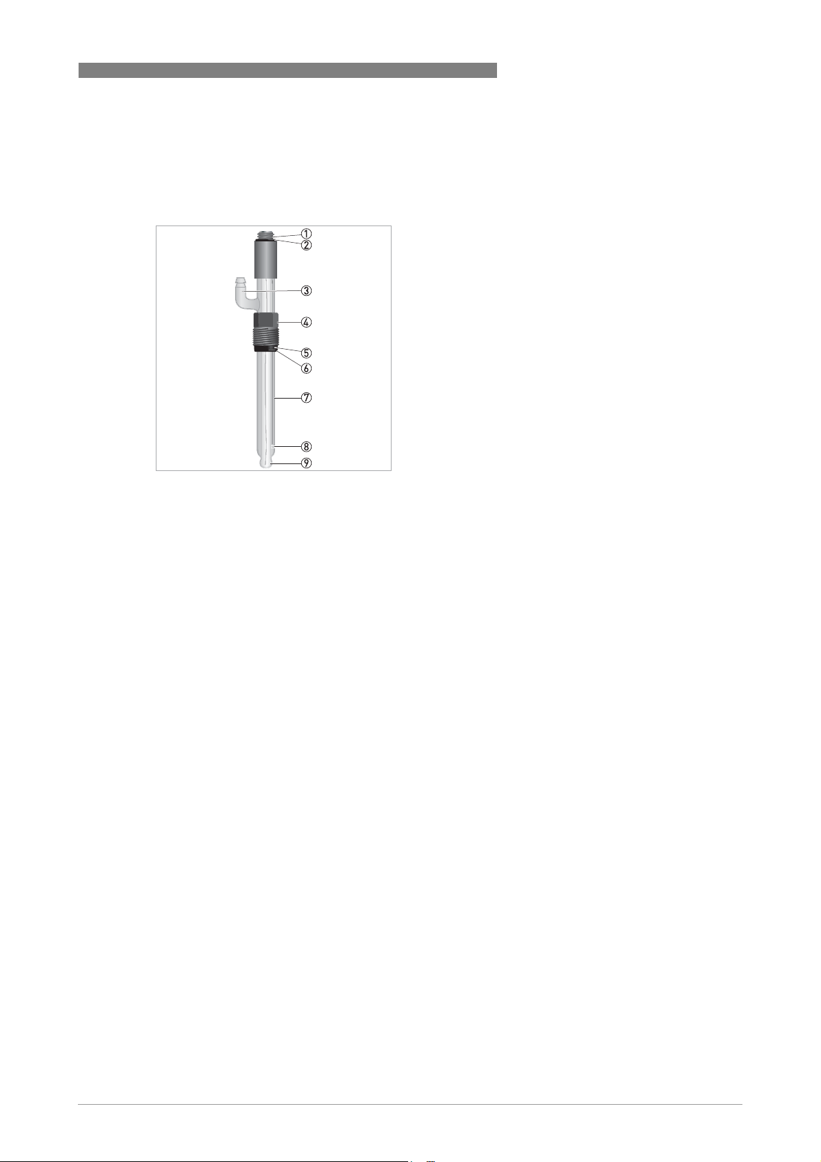
Figure 2-2: Sensor types
1 Cable connector DIN coax
2 O-ring
3 Refill hose connecting
4 Mounting Kit PG 13.5 (optional)
5 Washer
6 O-ring
7 Glass
8 Glass sleeve diaphragm
9 pH sensitive glass
www.krohne.com09/2012 - 4002314801 - MA OPTISENS PH 9100 R02 en
9
Page 10
2 DEVICE DESCRIPTION
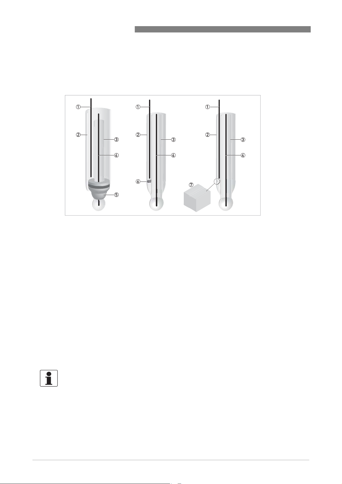
The OPTISENS PH 9100 is manufactured using a pH sensitive special glass which can be used in
almost all standard water applications due to its wide measuring range.The pH sensors are
available with different diaphragms:
OPTISENS PH 9100
Figure 2-3: Diaphragm types
1 Reference electrode
2 KCl solution
3 Inner pH 7 buffer solution
4 Measuring electrode
5 PTFE diaphragm
6 Ceramic diaphragm
7 Open diaphragm
pH sensor with open diaphragm and Pt100
open diaphragm (microscopically small hole in the glass); integrated Pt100 temperature
measurement; suitable for cooling water, wastewater and chemical industry applications.
pH sensor with ceramic diaphragm
Ceramic diaphragm; suitable for drinking water and pool industry applications.
pH sensor with PTFE diaphragm
Dirt-repellent Teflon diaphragm; suitable for wastewater, surface water and process water
applications.
2.3 Nameplate
INFORMATION!
Look at the device nameplate to ensure that the device is delivered according to your order.
Check for the correct supply voltage printed on the nameplate.
10
The sensor type is specified on the labelling of the sensor package and on the sensor itself.
www.krohne.com 09/2012 - 4002314801 - MA OPTISENS PH 9100 R02 en
Page 11

OPTISENS PH 9100
3.1 Notes on installation
INFORMATION!
Inspect the cartons carefully for damages or signs of rough handling. Report damage to the
carrier and to the local office of the manufacturer.
INFORMATION!
Do a check of the packing list to make sure that you have all the elements given in the order.
INFORMATION!
Look at the device nameplate to ensure that the device is delivered according to your order.
Check for the correct supply voltage printed on the nameplate.
3.2 Storage and transport
CAUTION!
Do not store the sensor tip dry. This will shorten lifetime considerably.
Always store the pH sensor tip wet in a 3 molar KCl solution when not in use. Saltless water
must be avoided since this would leak the KCl ions. The original packing in which the sensor tip
was delivered contains a plastic tube with KCl solution and therefore is suitable for storage and
transport (see following drawing).
INSTALLATION 3
• Since the pH sensor is made out of glass it is very fragile. Avoid shocks of any kind.
• Do not touch or scratch the pH sensitive glass tip of the sensor.
• Store the sensor in its original packaging in a dry, dust-free location. Keep it away from dirt. If
necessary, clean it as described on page 37.
www.krohne.com09/2012 - 4002314801 - MA OPTISENS PH 9100 R02 en
11
Page 12

3 INSTALLATION
Figure 3-1: pH sensor in its original packaging
1 Plastic tube filled with 3 molar KCl solution
2 pH sensor
3 O-ring
4 Washer
5 Protective cap over electrical connector
6 Sealing cap without hole to seal plastic tube 2 when sensor is in use
Storing the sensor in the provided plastic tube
• Screw the sealing cap off the plastic tube. Keep it in the original packaging.
• If there is not enough KCl solution in the plastic tube, fill it up with 3 molar KCl solution.
• Insert the sensor tip through the hole in the storage cap (see drawing on page 13).
• Carefully push the O-ring delivered with the storage cap on the sensor so that the cap sits over
the O-ring.
• Insert the sensor tip into the plastic tube until it is fully covered with KCl solution.
• Tighten the cap.
• Store the sensor in its original packaging.
OPTISENS PH 9100
3.3 Installation procedure
Because a new pH sensor needs to be calibrated before it is installed into its final measuring
location, it is important to follow the installation order:
1. Unpack the sensor.
2. Connect the sensor to the signal converter.
3. Calibrate the sensor.
4. Install the sensor into its final measuring location.
The required steps are explained in the following sections.
12
www.krohne.com 09/2012 - 4002314801 - MA OPTISENS PH 9100 R02 en
Page 13
OPTISENS PH 9100
3.4 Pre-installation requirements
CAUTION!
•
Never touch or scratch the pH sensitive glass tip of the sensor.
•
Make sure that the glass tip is clean and dust-free. If necessary, clean the tip as described on
page 37
INSTALLATION 3
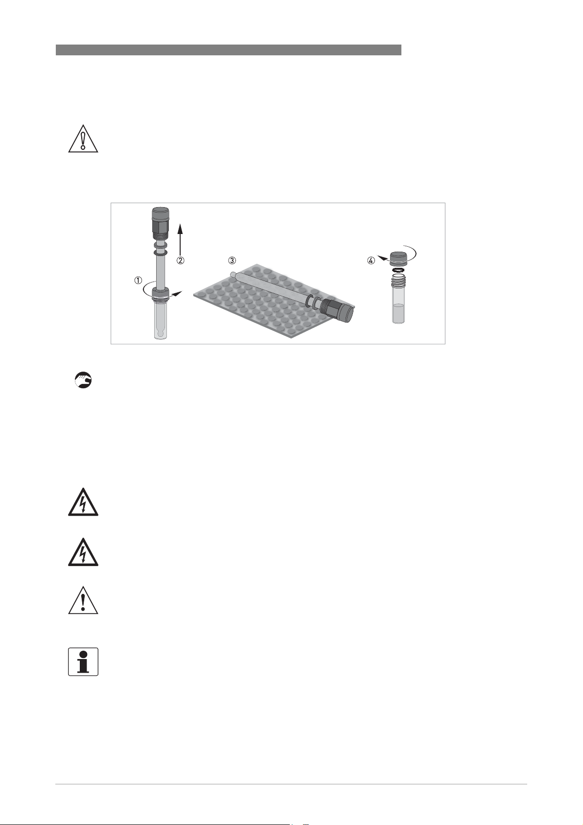
Figure 3-2: Handling the sensor
Unpacking the sensor
• Loosen the storage cap which is screwed or/and pushed on to the plastic tube 1.
• Gently pull the sensor out of the plastic tube 2.
• Lay the sensor on a soft mat/tissue 3.
• Screw or push the provided sealing cap on to the plastic tube, using O-ring as shown in the
drawing 4. Keep the storage cap (the one with the hole in it) in the original packaging.
3.5 Electrical connection
DANGER!
All work on the electrical connections may only be carried out with the power disconnected. Take
note of the voltage data on the nameplate!
DANGER!
Observe the national regulations for electrical installations!
WARNING!
Observe without fail the local occupational health and safety regulations. Any work done on the
electrical components of the measuring device may only be carried out by properly trained
specialists.
INFORMATION!
Look at the device nameplate to ensure that the device is delivered according to your order.
Check for the correct supply voltage printed on the nameplate.
www.krohne.com09/2012 - 4002314801 - MA OPTISENS PH 9100 R02 en
13
Page 14
3 INSTALLATION
3.5.1 Connecting the sensor cable to the signal converter
DANGER!
All work on the electrical connections may only be carried out with the power disconnected. Take
note of the voltage data on the nameplate!
INFORMATION!
Look at the device nameplate to ensure that the device is delivered according to your order.
Check for the correct supply voltage printed on the nameplate.
OPTISENS PH 9100
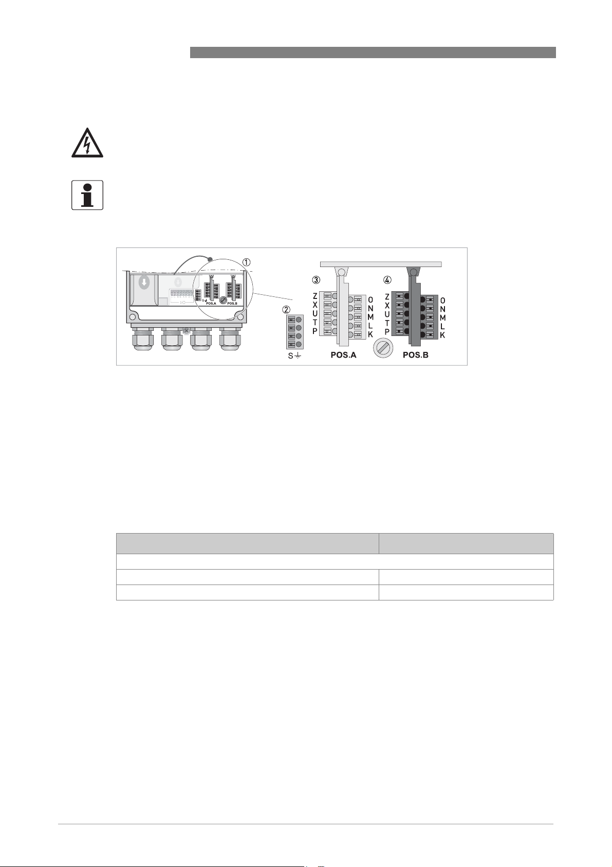
Figure 3-3: Sensor connection terminals on the signal converter dual channel version with terminal block A+B
1 Sensor connection terminals
2 Terminal block S (protective earth)
3 Terminal block A: terminals for sensor and temperature
4 Terminal block B: terminals for sensor and temperature
The pH sensors are available without internal Pt100 temperature sensor. The pH sensors
without integrated Pt100 temperature sensor are connected to the signal converter using a coax
cable.
When ordering the one channel version, only the interface "Pos.A" is populated. In the version
with two channels the interfaces "Pos.A" and "Pos.B" are populated.
Wire Terminal block Pos.A/B
OPTISENS PH 9100 with coax cable (without integrated Pt100/1000)
Coax shield (red) N (ref.)
Coax core (transparent) O (pH/ORP)
14
www.krohne.com 09/2012 - 4002314801 - MA OPTISENS PH 9100 R02 en
Page 15

OPTISENS PH 9100
Figure 3-4: Connecting the sensor cable
The following instructions describe the connection of the different sensor cables.
Connecting the sensor cable to the signal converter
• Thread the sensor cable through the outer right cable gland 1.
• Push the coax shield 4 into terminal N 2 and the coax core into terminal O 3.
• To remove a cable, press down the white clip 5 on the corresponding terminal and pull the
cable out 6.
INSTALLATION 3
3.5.2 Connecting the external temperature sensor
Connect an external Pt100 or Pt1000 sensor to terminal block Pos.A/B of the signal converter
according to the following drawings:
Figure 3-5: Connection of an external Pt100/1000 temperature sensor to the signal converter
1 2-wire connection
2 3-wire connection
www.krohne.com09/2012 - 4002314801 - MA OPTISENS PH 9100 R02 en
15
Page 16

3 INSTALLATION
3.5.3 Connecting the cable to the sensor
CAUTION!
Moisture inside the sensor connector must be avoided! Moisture will shortcut the mV signal
between the electrodes and deliver erratic readings!
If moisture has entered the connector dry it with air (e.g. hair blower).
Figure 3-6: Connecting the cable to the sensor
OPTISENS PH 9100
Connecting the cable to the sensor
• Unscrew the protective cap from the sensor connector and keep it for future use 1.
• Ensure that both cable and sensor connector are absolutely dry 2.
• Make sure that the O-ring is positioned on the sensor connector 3.
• Screw the cable connector 4 on to the sensor and tighten it by hand.
3.6 Calibrating the sensor
Before the sensor is installed, it has to be calibrated. Proceed as described on page 27. Then
continue with the installation procedure.
16
www.krohne.com 09/2012 - 4002314801 - MA OPTISENS PH 9100 R02 en
Page 17

OPTISENS PH 9100
3.7 Installing the sensor
3.7.1 General installation instructions
The sensor tip must always have full contact with the measuring medium.
The mounting position of the sensor should not deviate more than 75° from vertical position
(sensor tip pointing downwards). Doing otherwise might cause internal air bubbles to float into
the sensor glass tip. This would interrupt the electrical contact between the inner buffer solution
and the glass surface.
INSTALLATION 3
Figure 3-7: Installation requirements
1 Measuring medium
2 Maximum deviation of 75° from vertical position
www.krohne.com09/2012 - 4002314801 - MA OPTISENS PH 9100 R02 en
17
Page 18

3 INSTALLATION
3.7.2 Mounting to a flow-through holder
WARNING!
Ensure that the pipe is without pressure before installing or removing a sensor!
INFORMATION!
The flow-through holder is an optional accessory and not part of the standard scope of delivery.
It has to be installed horizontally in pump or sample lines or directly in the process.
Figure 3-8: Possible mounting positions of the flow-through holder
1 Mounting in an outlet pipe
2 Mounting in a bypass pipe
3 Valve
4 Flow-through holder
OPTISENS PH 9100
18
Figure 3-9: Installing the sensor into the flow-through holder
1 Flow-through holder
2 Female thread
3 Sensor thread
4 Washer
5 O-ring
6 Process connection
7 Flow direction
8 Protective cage
Installing a new sensor
• Make sure that the O-ring 5 and the washer 4 on the sensor are assembled in the sequence
indicated in the drawing.
• Screw the sensor into the female thread 2 of the flow-through holder 1. Tighten the sensor
by hand.
• If you have not yet established the electrical connection to the signal converter, leave the
protective cap on the sensor until you establish the electrical connection.
www.krohne.com 09/2012 - 4002314801 - MA OPTISENS PH 9100 R02 en
Page 19

OPTISENS PH 9100
3.8 Installing an external temperature sensor
Since the slope of the pH sensor is temperature-dependent, a temperature compensation makes
sense if the temperature of your measuring medium varies.
If the pH sensor does not have an integrated Pt100/1000 temperature sensor, you should use an
external temperature sensor. There are various different possibilities of adding an external
temperature sensor to your pH measurement installation. They can not be explain in detail in
this document. Nevertheless, you should follow the general guidelines.
General guidelines for external temperature sensor installation
• The temperature sensor should be calibrated using a reference thermometer. For further
information refer to
• The temperature should be measured close to the pH sensor in the same medium to avoid
temperature differences. For example, surface water may have a different temperature than
deeper water.
Suitable external temperature sensors are
• Pt100 in 2-wire or 3-wire connection
• Pt1000 in 2-wire or 3-wire connection
Temperature compensation
INSTALLATION 3
on page 27.
www.krohne.com09/2012 - 4002314801 - MA OPTISENS PH 9100 R02 en
19
Page 20

3 INSTALLATION
3.9 Examples of a typical measuring point
The following examples each show the signal converter, a sensor with or without integrated
temperature measurement, and the flow-through or immersion holder.
OPTISENS PH 9100
Figure 3-10: Measuring point using the flow-through holder
1 Bypass measurement
2 Outlet measurement
3 Elbow pipe
4 Sample vial
5 Flow-through holder with sensor
6 Shut-off valve
7 Bypass pipe
8 Main pipe
1 23
20
Figure 3-11: Measuring point using the immersion holder
1 pH/ORP or pH/ORP + temperature
2 pH or pH + temperature
3 ORP + temperature
www.krohne.com 09/2012 - 4002314801 - MA OPTISENS PH 9100 R02 en
Page 21

OPTISENS PH 9100
4.1 Menu mode structure
INFORMATION!
The following table just presents an overview. When programming the device, always consult the
function tables additionally as they contain further information!
Only the sensor relevant menus are shown in the following tables. For detailed information
about the general setting refer to the MAC 100 signal converter manual.
OPERATION 4
Measuring
mode
3 or 4
pages,
scrolling
with ↓ or ↑
Main menu Submenu Parameter
>2.5
A
s
quick
^
setup
>^A9.1 temp.comp. >^A9 pH cal. A
process input A pH calibration
(for dual channel version; refer
to pH/ORP sensor
documentation for further
information)
A12.1 start calib. ORP A12 ORP calibration B
Only if switched to ORP!
process input B ORP calibration
(for dual channel version; refer
to pH/ORP sensor
documentation for further
information)
A13.1 temp.comp. A13 pH cal. B
process input B pH calibration
(for dual channel version; refer
to pH/ORP sensor
documentation for further
information)
>^For further
information
see function
tables.
www.krohne.com09/2012 - 4002314801 - MA OPTISENS PH 9100 R02 en
21
Page 22

4 OPERATION
OPTISENS PH 9100
Measuring
mode
3 or 4
pages,
scrolling
with ↓ or ↑
Main menu Submenu Parameter
>2.5
B test >^B1 sim.process inp.A >^B1.1 temperature >^For further
s
^
B2 sim.process inp.B B 2.1 temperature
B3 simulation I/O B3.1 current out A
B4 actual values B4.1 operating hours
B5 logbooks B5.1 status log
B6 information B6.1 C number
↓↑ ↓↑ ↓↑ ↓↑
B1.5 ORP
Only if switched to ORP! (for
dual channel version; refer to
pH/ORP sensor documentation
for further information)
B1.7 pH
(for dual channel version; refer
to pH/ORP sensor
documentation for further
information)
B2.5 ORP
Only if switched to ORP!
(for dual channel version; refer
to pH/ORP sensor
documentation for further
information)
B2.7 pH
(for dual channel version; refer
to pH/ORP sensor manual for
further information)
B3.2 current out B
B3.3 current out C
B3.6 simulation R3
B4.2 process input A
B4.2.1 temperature
B4.2.2 pH/ORP
B4.2.9 CPU temp. (depends on V
number)
B4.2.11 electrode current
B4.3 process input B
B4.3.1 temperature
B4.3.2 pH/ORP
B4.3.9 CPU temp. (depends on
Vnumber)
B4.3.11 elctrode current
B5.2 calibration log
B6.2 process input A
B6.3 process input B
B6.4 SW.REV.MS
B6.5 SW.REV.UIS
B6.6 Electronic Revision ER
information
see function
tables.
22
www.krohne.com 09/2012 - 4002314801 - MA OPTISENS PH 9100 R02 en
Page 23

OPTISENS PH 9100
OPERATION 4
Measuring
mode
3 or 4
pages,
scrolling
with ↓ or ↑
Main menu Submenu Parameter
>2.5
s
^
C
setup>^
↓↑ ↓↑ ↓↑ ↓↑
C1 process input A >^C1.1 parameter (pH/ORP) >^For further
C1.7 inner buffer (only pH)
C1.8 zero point
C1.9 slope
C1.10 calibration buffers
C1.14 time constant
C1.15 temperature
C1.16 ORP cal.
C1.17 pH cal.
C2 process input B
(for dual channel version;
refer to pH/ORP sensor
manual for further
information)
C2.1 parameter (pH/ORP)
C2.7 inner buffer (only pH)
C2.8 zero point
C2.9 slope
C2.10 calibration buffers
C2.14 time constant
C2.15 temperature
C2.16 ORP cal.
C2.17 pH cal.
information
see function
tables.
4.2 Function tables
4.2.1 Menu A, quick setup
INFORMATION!
Note that the appearance of some sub-menus depends on the hardware setting and the used
sensor(s). Also only the sensor relevant menus and submenus are shown here in detail. For all
other menu functions refer to the MAC 100 signal converter manual.
A9, ph cal. B
For single or dual channel version: Settings for sensor calibration
A12, process input B ORP calibration
For dual channel version; refer to pH/ORP sensor manual for further information.
Only if switched to ORP!
A13, process input B pH calibration
For dual channel version; refer to pH/ORP sensor manual for further information.
www.krohne.com09/2012 - 4002314801 - MA OPTISENS PH 9100 R02 en
23
Page 24

4 OPERATION
4.2.2 Menu B, test
INFORMATION!
Note that the appearance of some sub-menus depends on the hardware setting and the used
sensor(s). Also only the sensor relevant menus and sub-menus are shown here in detail. For all
other menu functions refer to the MAC 100 signal converter manual.
The procedure to start the simulation process is the same for all functions:
• Choose the function with the help of ↓ or ↑ and press ^.
i You see the two options "set value" (opens the editor to enter the simulation value) and
"break" (exits the menu without simulation).
• Choose the desired option with the help of ↑ or ↓ and press ^.
i If you chose "set value", the device asks "start simulation" and offers the options "no" (exits
the menu without simulation) or "yes" (starts the simulation finally).
• Choose the desired option with the help of ↑ or ↓ and press ^.
i If you chose "yes", the simulation starts.
OPTISENS PH 9100
B1,sim.process inp.A B2,sim.process inp.B
Level Designation / function Settings / descriptions
B1.1
B2.1
B1.5
B2.5
B1.7
B2.7
temperature In this menu the temperature can be simulated.
ORP
ONLY if switched to ORP!
(for dual channel version
only; refer to pH/ORP
sensor manual for further
information)
pH
(for dual channel version
only; refer to pH/ORP
sensor manual for further
information)
In this menu the relative concentration of ORP can be simulated. For dual
channel version only; refer to pH/ORP sensor manual for further
information. ONLY if switched to ORP!
In this menu the relative concentration of pH can be simulated. For dual
channel version only; refer to pH/ORP sensor manual for further
information.
B4, actual values
Level Designation / function Settings / descriptions
This menu groups several functions which allow to display the corresponding actual reading. The shown measurements
are depending on the device configuration.
B4.1 operating hours This menu shows the operating time of the devices in hours.
B4.2 process input A In this menu the measurements from process input A can be read.
B4.3 process input B In this menu the measurements from process input B can be read.For dual
channel version only; refer to pH/ORP sensor manual for further
information.
24
www.krohne.com 09/2012 - 4002314801 - MA OPTISENS PH 9100 R02 en
Page 25

OPTISENS PH 9100
OPERATION 4
4.2.3 Menu C, setup
INFORMATION!
The signal converter has a dual process input, A and B. Each process input has an own submenu
in this main menu. Process input A is always present, i.e. there is always a board in the interface
"Pos.A" in the connection area. The interface of process input B only has a board with the dual
channel signal converter. Be aware that the definition which kind of measurement a process
input can do is defined when ordering the device. The configuration cannot be changed later.
INFORMATION!
Note that the appearance of some submenus depends on the hardware setting and the used
sensor(s).
C1, process input A C2, process input B
Level Designation / function Settings / descriptions
Process input A and B can be either a sensor 1 or a sensor 2. Further information about the type of sensor 1 or 2 please
refer to MAC 100 manual "Sensor input combinations". Process input A is always present, process Input B can be
present.
Note: The exchange of a sensors 1 with a sensor 2, or vice versa, can only be done by the manufacturer!
Depending on the sensor which is connected to a slot A or B the menu changes.
C1.1
C2.1
C1.7
C2.7
C1.8
C2.8
C1.9
C2.9
C1.10
C2.10
C1.15
C2.15
C1.15.1
C2.15.1
C1.15.2
C2.15.2
C1.15.3
C2.15.3
C1.15.4
C2.15.4
parameter pH
parameter ORP
inner buffer Setting for inner buffer of the pH sensor.
zero point This menu item shows the actual zero point to the calibrated pH/ORP
slope This menu item shows the actual slope point to the calibrated pH/ORP
calibration buffer This menu item shows the used buffer concentration for the last calibration.
temperature Menu for temperature measurement. Available for sensor 1 and sensor 2.
probe Options:
This menu item is for selecting the probe which is connected to process
input A/B. The entries of this selection depends on the chosen device
configuration. The device configuration is customer specific and set during
production.
sensor.
sensor.
• manual: used if no integrated or external temperature sensor is connected
to the signal converter.
• Pt100: used if the pH sensor has an integrated Pt temperature
measurement or if an external Pt100 temperature sensor is connected to
the signal converter.
• Pt1000: used if an external Pt1000 temperature sensor is connected to the
signal converter.
• process input A: choose this option if there is a temperature sensor
connected to input A of the signal converter.
manual Only available if C1.15.1 or C2.15.1 is set to "manual".
correction Offset correction for temperature measurement. Not available if C1.15.1 or
limitation Measuring ranges for temperature measurement.
C2.15.1 is set to "manual".
www.krohne.com09/2012 - 4002314801 - MA OPTISENS PH 9100 R02 en
25
Page 26

4 OPERATION
Level Designation / function Settings / descriptions
OPTISENS PH 9100
C1.15.5
C2.15.5
C1.16
C2.16
C1.16.1
C2.16.1
C1.16.2
C2.16.2
C1.16.3
C2.16.3
C1.16.4
C2.16.4
C1.17
C2.17
C1.17.1
C2.17.1
C1.17.3
C2.17.3
C1.17.4
C2.17.4
C1.17.6
C2.17.6
C1.17.7
C2.17.7
temp. comp. Menu for activating the temperature compensation parameters for the
measurement.
Options:
• Linear: linear temperature compensation.
• Off: temperature compensation is disabled.
ORP cal. Menu item for calibrating the ORP sensor.
prepare calibration View actual ORP value.
ref. value ORP Enter the reference value of the probe in mV.
start calibration? Start calibration procedure.
stored value View stored value of calibration.
pH cal. Menu item for calibration the pH sensor.
temp.comp Menu for activating the temperature compensation parameters for the
calibration.
Options:
• off: temperature measurement is disabled.
• manual: temperature value has to be entered manually.
• automatic: temperature measurement is performed as configured.
calib. buffer 1 Start calibration procedure in buffer 1.
pH 1 set value Enter the reference value of the probe in pH.
calib. buffer 2 Start calibration procedure in buffer 2.
pH 2 set value Enter the reference value of the probe in pH.
CAUTION!
If you choose for measurement the temperature compensation "linear" than choose between
"automatic" or "manual" for the temperature compensation during calibration. If you choose for
measurement the temperature compensation "off" than choose also "off" for the temperature
compensation during calibration.
26
www.krohne.com 09/2012 - 4002314801 - MA OPTISENS PH 9100 R02 en
Page 27

OPTISENS PH 9100
4.3 Calibration
4.3.1 Temperature compensation
There are three basic options for temperature compensation:
• automatic: the signal converter will automatically compensate temperature influences using
the information of a Pt100 or Pt1000 temperature sensor.
• manual: the signal converter will compensate temperature influences using a manually
entered value; this option only makes sense if the temperature of the measured medium is
quite constant.
• off: temperature compensation is disabled.
INFORMATION!
If you choose no compensation, the measured pH value will most likely deviate from the actual
pH value. The reason is that the pH value of a specific medium varies depending on the
temperature of the medium.
OPERATION 4
The menu for the type of temperature compensation offers the following options:
• Pt1000: choose this option if there is an external Pt1000 temperature sensor connected to the
signal converter.
• Pt100: choose this option if the sensor has an integrated Pt100 temperature measurement or
if there is an external Pt100 temperature sensor connected to the signal converter.
• manual: choose this option if there is no integrated or external temperature sensor
connected to the signal converter.
• process input A: choose this option if there is a temperature sensor connected to input A of
the signal converter.
INFORMATION!
In the basic configuration the setting of the temperature compensation is Pt100. If you use a pH
sensor without Pt100/1000 than select the temperature compensation "manual" and enter the
value. Otherwise an error will be displayed.
www.krohne.com09/2012 - 4002314801 - MA OPTISENS PH 9100 R02 en
27
Page 28

4 OPERATION
After starting-up the signal converter, the measuring screen appears. This is the standard
screen which is displayed automatically in the normal operating mode. If you are in this mode
and you want to adjust the temperature compensation, you have to perform the following steps:
Step 1: activating the temperature compensation for measurement
• Press > for more than 2.5 seconds, then release the button. You are on the main menu level. In the
upper line of the display "A" appears, beneath the main menu quick setup is highlighted.
• Press or until the main menu setup is highlighted.
MAIN MENU
A quick setup
B test
> C setup
D service
• Press > to enter the chosen menu.
OPTISENS PH 9100
You are on the first submenu level. In the upper line of the display "setup" and "c1" appears,
beneath the submenu process input A is highlighted.
• Press or to select process input A or process input B. Choose process input A or B
where ever pH is configurated.
• Press > to enter the chosen menu.
You are on the second submenu level. The submenu parameter is highlighted.
• Press > to enter the chosen menu.
You are on the third submenu level. In the upper line of the display "parameters"
appears.
• Press or to select pH.
• Press ^ to confirm the entered value.
You are on the second submenu level. The submenu parameter is highlighted.
• Press or to select temperature.
• Press > to enter the chosen menu.
You are on the third submenu level. In the upper line of the display "temperature"
and "C1.15.1" or "C2.15.1" appears, beneath the option probe is highlighted.
• Press or to select temp.comp.
• Press > to enter the chosen menu.
You are on the fourth submenu level. In the upper line of the display
"temp.comp" appears.
Now you can setup the temperature compensation.
• Press or to choose between automatic or off.
• Press ^ to confirm the entered value.
You are on the third submenu level. If you have chosen the option automatic, you
can select the type of temperature compensation now.
• Press or to choose probe.
• Press > to enter the chosen menu.
You are on the fourth submenu level. Press or to choose between
Pt100, Pt1000, manual or process input A.
• Press ^ to confirm the entered value.
• Press ^ several time until you reach the measuring mode again. Choose
yes to safe and confirm your selection.
28
INFORMATION!
When ordering the dual channel version, the interface "Pos A" and "Pos B" are populated. A
separate temperature sensor has to be connected to "Pos A" and configurated on process input
A. To connect a sensor with integrated Pt100/Pt1000, the integrated temperature sensor has to
be connected on the same terminal block as the sensor.
www.krohne.com 09/2012 - 4002314801 - MA OPTISENS PH 9100 R02 en
Page 29

OPTISENS PH 9100
Step 2: Configure /adjust the temperature sensor
Step 2a: probe Pt100/1000
Read the currently measured temperature of the Pt100/1000 temperature sensor from the measurement
screen and write it down.
Measure the temperature with a reference thermometer and check if it deviates from the temperature
measured by the Pt100/1000.
• Press > for more than 2.5 seconds, then release the button. You are on the main menu level. In the
upper line of the display "A" appears, beneath the main menu setup is highlighted.
• Press or until the main menu setup is highlighted.
• Press > to enter the chosen menu.
OPERATION 4
MAIN MENU
A quick setup
B test
> C setup
D service
You are on the first submenu level. In the upper line of the display "setup" and "c1" appears,
beneath the submenu process input A is highlighted. Choose process input A or B where ever
pH is configurated.
• Press or to select process input A or process input B.
• Press > to enter the chosen menu process input A/B.
You are on the second submenu level. Press or until the submenu temperature is
highlighted.
• Press > to enter the chosen menu. The submenu probe is highlighted.
• Press or until the submenu Pt100/1000 is highlighted.
• Press ^ to enter the chosen menu.
• If necessary, enter the temperature correction in Kelvin so that the signal converter shows the
same temperature as the reference thermometer. Press ^ to confirm the entered value. The
temperature sensor has been adjusted.
www.krohne.com09/2012 - 4002314801 - MA OPTISENS PH 9100 R02 en
29
Page 30

4 OPERATION
Step 2b: probe manual
Measure the temperature of the measuring medium.
• Press > for more than 2.5 seconds, then release the button. You are on the main menu level. In the
upper line of the display "A" appears, beneath the main menu setup is highlighted.
• Press or until the main menu setup is highlighted.
MAIN MENU
A quick setup
B test
> C setup
D service
• Press > to enter the chosen menu.
OPTISENS PH 9100
You are on the first submenu level. In the upper line of the display "setup" and "c1" appears,
beneath the submenu process input A is highlighted. Choose process input A or B where ever
pH is configurated.
• Press or to select process input A or process input B.
• Press > to enter the chosen menu process input A/B.
You are on the second submenu level. Press or until the submenu temperature is
highlighted.
• Press > to enter the chosen menu. The submenu probe is highlighted.
• Press or until the submenu manual is highlighted.
• Press ^ to enter the chosen menu.
• Enter the measured temperature. Press ^ to confirm the entered value. The manually
measured temperature will now be used for temperature compensation.
• Step 2c: probe process input A
The temperature sensor connected to input A of the signal converter is used for temperature
compensation.
The temperature sensor probe process input A has to configured in submenu process input A.
If you use a Pt100/1000 follow the instruction in step 2.1. If you use manually entered value,
follow the instruction in step 2.2.
30
www.krohne.com 09/2012 - 4002314801 - MA OPTISENS PH 9100 R02 en
Page 31

OPTISENS PH 9100
4.3.2 Calibrating pH measurement
A pH calibration is necessary in regular intervals or when installing a new pH sensor.
In an intact sensor, the optimal slope is 59 mV for each pH unit and the optimal zero point is 0 mV
at pH 7. The slope should at least have a value between 50...65 mV per pH unit. Re-calibrate the
sensor if the slope does not approximate those limits.
The pH sensor ages, the slope gets flatter and the zero error increases. When one or both of
these values exceed certain limits, the converter displays a message indicating that the sensor
has to be exchanged.
CAUTION!
•
Never touch or scratch the pH sensitive glass tip of the sensor.
•
Make sure that the glass tip is clean and dust-free. If necessary, clean the tip as described on
page 37
CAUTION!
Moisture inside the sensor connector must be avoided! Moisture will shortcut the mV signal
between the electrodes and deliver erratic readings!
If moisture has entered the connector dry it with air (e.g. hair blower).
.
OPERATION 4
To avoid alarms on the process control system when temporarily removing the sensor (i.e. for
maintenance), the converter has a hold function. This function "freezes" all outputs (i.e. the
display and the current outputs) of the last measured value.
INFORMATION!
As an indication that the manual hold function is active, the "warning sign" in the upper left
corner of the display appears. Meanwhile the status messages show "checks in progress". For
more details about how to select the manual hold function refer to the converter manual.
After starting-up the converter, the measuring screen appears. This is the standard screen
which is displayed automatically in the normal operating mode. If you are in this mode and you
want to initiate a calibration, you have to activate the manual hold function in the first step.
www.krohne.com09/2012 - 4002314801 - MA OPTISENS PH 9100 R02 en
31
Page 32

4 OPERATION
Step 1: activating the manual hold function
• Press > for more than 2.5 seconds, then release the button. You are on the main menu level. In the
upper line of the display "A" appears, beneath the main menu quick setup is highlighted.
• Press or until the main menu quick setup is highlighted.
MAIN MENU
> A quick setup
B test
Csetup
D service
• Press > to enter the chosen menu.
OPTISENS PH 9100
You are on the first submenu level. In the upper line of the display "quick setup" and
A1" appears, beneath the submenu language is highlighted.
• Press or until the submenu manual hold is highlighted.
• Press > to enter the chosen menu.
You are on the second submenu level. In the upper line of the display
"manual hold" appears, beneath the option off is highlighted
• Press or to choose the option "on"
• Press ^ to confirm the entered value.
• You have activated the manual hold function. To go to the next step and prepare the calibration
procedure. You have to return to the measuring mode.
• Press ^ until you reach the measuring mode again
Step 2: preparing the calibration procedure
• If you re-calibrate an existing sensor, remove the sensor from its respective assembly
(for further information refer to
Calibrating pH measurement
Mounting to a flow-through holder
on page 31).
• If you calibrate a new sensor, make sure that the sensor is correctly connected to the
converter.
• Check the sensor for damages, check the diaphragm for coating and rinse the sensor tip with
tap water and gently swipe it with a soft tissue.
• Provide two buffer solutions with the same known temperature: pH 4 and pH 7.
After activating the manual hold function and the preparative measures, you can get access to
the calibration procedure from the measuring mode in two different ways. Either you go via the
main menu setup (step 3a) or via the main menu quick setup (step 3b).
on page 18 or refer to
32
www.krohne.com 09/2012 - 4002314801 - MA OPTISENS PH 9100 R02 en
Page 33

OPTISENS PH 9100
Step 3a: accessing the calibration menu via the main menu setup
• Press > for more than 2.5 seconds, then release the button. You are on the main menu level. In the
upper line of the display "A" appears, beneath the main menu quick setup is highlighted.
• Press or until the main menu setup is highlighted.
OPERATION 4
MAIN MENU
A quick setup
B test
> C setup
D service
• Press > to enter the chosen menu.
You are on the first submenu level. In the upper line of the display "setup" and "c1"
appears, beneath the submenu process input A is highlighted.
• Press or to select process input A or process input B is highlighted.
Choose process input A or B where ever pH is configured.
• Press > to enter the chosen menu.
You are on the second submenu level. In the upper line of the
display "process input A" and "C1.1" appears, beneath the
submenu parameter is highlighted.
• Press or until the submenu pH cal. is highlighted.
• Press > to enter the chosen menu.
• You can start the calibration procedure now as described in "Step 4".
Step 3b: accessing the calibration menu via the main menu quick setup
• Press > for more than 2.5 seconds, then release the button. You are on the main menu level. In the
upper line of the display "A" appears, beneath the main menu quick setup is highlighted.
MAIN MENU
> A quick setup
B test
C setup
D service
• Press > to enter the chosen menu.
You are on the first submenu level. In the upper line of the display "quick
setup" and "a" appears, beneath the submenu language is highlighted.
• Press or until the submenu pH cal. A or B is highlighted, wherever pH
is configurated
• Press > to enter the chosen menu.
• You can start the calibration procedure now as described in "Step 4".
www.krohne.com09/2012 - 4002314801 - MA OPTISENS PH 9100 R02 en
33
Page 34

4 OPERATION
Figure 4-1: Calibration procedure
Step 4: calibration procedure
• After choosing the submenu pH cal. (step 3a) or pH cal. A or B (step 3b) in the previous steps,
continue by pressing >.
i The signal converter demands to choose the kind of temperature compensation for the
calibration. You have the options "off", "automatic" and "manual" (for detailed information
refer to
temperature compensation for the calibration as for the measurement.
• If you chose "automatic", just press ^. If you chose "manual", first enter the temperature of
the buffer solutions using or and then press ^.
i On the screen the message calib. buffer 1 appears.
Temperature compensation
OPTISENS PH 9100
on page 27). Please select the same kind of
• Submerge the sensor tip into the pH 7 buffer solution 1.
i The currently measured value is shown on the display.
• Wait until a steady value is displayed, then press ^.
• Press ^ to finally start the calibration procedure.
i The message pH 1 set value and the pH value of the first buffer solution are displayed on
the screen.
• Press ^ to confirm the settings.
• After 25 seconds the calibration step is completed and calib. buffer 2 appears. Otherwise, If
the shown value deviates from the buffer solution, enter the correct value using or .
• Press ^ to confirm the entered value.
i On the screen the message calib. buffer 2 appears.
• Rinse the sensor tip with tap water 2 and clean it with a soft tissue.
• Submerge the sensor tip into the pH 4 buffer solution 3.
i The currently measured value is shown on the display.
• Wait until a steady value is displayed.
• Press ^ to continue the calibration procedure.
i The message pH 2 set value and the pH value of the second buffer solution are displayed on
the screen.
• Press ^ to confirm the setting.
• After 25 seconds the calibration step is completed. Otherwise, if the shown value deviates
from the buffer solution, enter the correct value using or .
• Press ^ to confirm the entered value.
i The zero point of the sensor is displayed (should be near 0 mV in an intact sensor).
34
www.krohne.com 09/2012 - 4002314801 - MA OPTISENS PH 9100 R02 en
Page 35

OPTISENS PH 9100
• Press ^ to confirm.
i The slope of the sensor is displayed (should be near 59 mV in an intact sensor).
• Press ^ to confirm.
i The message store cal. value? is displayed on the screen. The converter asks if the new
calibration values should be stored.
• Choose yes to store the calibration values. Choose no to discard the results.
• Press ^ to confirm.
i Prior returning to the measuring display, you are asked if the configuration should be
stored.
• Choose yes using or to store the new calibration values.
i You have completed the pH calibration.
• If you want to return to the measuring mode, press ^ several times until you reach this mode.
INFORMATION!
If an error occurs during the calibration procedure, the display shows an error message.
Possible causes for an error are:
•
Slope too flat.
•
Wrong buffer solution.
•
Wrong electrical connection.
•
Moisture in the sensor connector.
OPERATION 4
Step 5: re-installing the sensor
• After the calibration procedure, rinse the sensor with tap water.
• Reinstall the sensor into its assembly, refer to
Installing the sensor
Step 6: switching back to measurement
• Deactivate the function "manual hold" again.
on page 17.
www.krohne.com09/2012 - 4002314801 - MA OPTISENS PH 9100 R02 en
35
Page 36

4 OPERATION
4.3.3 Calibration log
INFORMATION!
In order to show the history of the calibrations, the signal converter has a calibration logbook
function. Up to 64 entries of the calibration history are stored including date and time.
Accessing the calibtration log
• Press > for more than 2.5 seconds, then release the button. You are on the main menu level. In the
upper line of the display "A" appears, beneath the main menu quick setup is highlighted.
• Press or until the main menu test is highlighted.
MAIN MENU
A quick setup
> B test
C setup
D service
Press > to enter the chosen menu.
OPTISENS PH 9100
You are on the first submenu level. In the upper line of the display "test" and "B1" appears,
beneath the submenu sim.process input A is highlighted.
Press or until the submenu logbooks is highlighted.
Press > to enter the chosen menu.
You are on the second submenu level. In the upper line of the display "logbooks" and
"B1" appears, beneath the submenu status log is highlighted.
Press or until the submenu calibration log is highlighted.
Press > to enter the chosen menu.
• You are on the data level and you see the calibration history. With the help of or you can
scroll through the different entries.
• If you want to return to the measuring mode press ^ several times until you reach this mode.
4.4 Troubleshooting
Problem Possible cause Remedy
The pH sensor
does not deliver a
signal.
The pH sensor
delivers an
unstable signal.
Mechanical damage of the
glass bulb, e.g. small
cracks. This will shortcut
the ion exchange and
deliver a pH7 reading.
Moisture inside the
sensor connector. This
will shortcut the signal
between pH glass half cell
and reference half cell
and deliver a reading of
pH7.
The diaphragm in the
reference half cell does
not provide good contact
to the process medium
due to drying up or
coatings.
Exchange sensor.
Clean the connector (sensor/cable) with pure water
and dry with air (e.g. hair blower).
• Clean the diaphragm with hot soap or acid using a
soft tissue (details on page 37).
• Submerge sensor in water and increase the
temperature to 50...60°C / 122...140°F.
• Submerge sensor in 3 molar KCl solution at ambient
temperature. The decrease in temperature will cause
the reference half cell to suck in KCl solution through
the diaphragm and regenerate the diaphragms
functionality.
36
www.krohne.com 09/2012 - 4002314801 - MA OPTISENS PH 9100 R02 en
Page 37

OPTISENS PH 9100
5.1 Maintenance
5.1.1 Cleaning
• Slight dirt residues or dust: Rinse the sensor tip with tap water and clean it with a soft tissue.
• Oily and greasy coatings: Remove with a warm soap solution and rinse with water.
• Hardness deposits or metal hydroxide deposits: Remove with 10% citric acid or hypochloric
acid and rinse with water.
5.1.2 Aging and re-calibration
During operation, but already during storage, pH senors age due to poisoning effects of the inner
buffer system. Therefore it is important to re-calibrate the sensors in regular intervals as
described.
When the sensor becomes too old to provide reliable measurements, the signal converter
displays an error message after the calibration procedure. In this case, the sensor has to be
exchanged.
Aging effects pH sensors:
• Decrease of slope due to abrasion, drying, corrosion of glass bulb coating and leaching: The
slope should be > 50 mV/pH. An optimal value is 59 mV/pH at 25°C/ 77°F. When the slope
drops below 50 mV/pH, an error message is displayed and the sensor has to be exchanged.
The slope of the sensor is displayed after each calibration procedure.
• Shift of zero point due to leaching / contamination of reference half cell or increased
resistance between glass bulb and reference half cell: The zero point should lie between
-58...+58 mV at pH 7. An optimal value is 0 mV at pH 7.
The zero point of the sensor is displayed after each calibration procedure.
SERVICE 5
The following figure shows the aging effects:
Figure 5-1: Aging effects of sensor
1 Horizontal shift of slope
2 Vertical shift of slope
3 Decrease of slope
www.krohne.com09/2012 - 4002314801 - MA OPTISENS PH 9100 R02 en
37
Page 38

5 SERVICE
INFORMATION!
The life time of a pH sensor can lie anywhere between 6 weeks and 2 years. The life time
expectation depends heavily on the application. The right choice of the sensor type is very
important.
5.2 Spare parts availability
The manufacturer adheres to the basic principle that functionally adequate spare parts for each
device or each important accessory part will be kept available for a period of 3 years after
delivery of the last production run for the device.
This regulation only applies to spare parts which are subject to wear and tear under normal
operating conditions.
5.3 Availability of services
The manufacturer offers a range of services to support the customer after expiration of the
warranty. These include repair, maintenance, technical support and training.
OPTISENS PH 9100
INFORMATION!
For more precise information, please contact your local sales office.
5.4 Returning the device to the manufacturer
5.4.1 General information
This device has been carefully manufactured and tested. If installed and operated in accordance
with these operating instructions, it will rarely present any problems.
CAUTION!
Should you nevertheless need to return a device for inspection or repair, please pay strict
attention to the following points:
•
Due to statutory regulations on environmental protection and safeguarding the health and
safety of our personnel, manufacturer may only handle, test and repair returned devices that
have been in contact with products without risk to personnel and environment.
•
This means that the manufacturer can only service this device if it is accompanied by the
following certificate (see next section) confirming that the device is safe to handle.
CAUTION!
If the device has been operated with toxic, caustic, flammable or water-endangering products,
you are kindly requested:
•
to check and ensure, if necessary by rinsing or neutralising, that all cavities are free from
such dangerous substances,
•
to enclose a certificate with the device confirming that is safe to handle and stating the
product used.
38
www.krohne.com 09/2012 - 4002314801 - MA OPTISENS PH 9100 R02 en
Page 39

OPTISENS PH 9100
5.4.2 Form (for copying) to accompany a returned device
Company: Address:
Department: Name:
Tel. no.: Fax no.:
Manufacturer's order no. or serial no.:
The device has been operated with the following medium:
SERVICE 5
This medium is: water-hazardous
toxic
caustic
flammable
We checked that all cavities in the device are free from such
substances.
We have flushed out and neutralized all cavities in the
device.
We hereby confirm that there is no risk to persons or the environment through any residual media
contained in the device when it is returned.
Date: Signature:
Stamp:
5.5 Disposal
CAUTION!
Disposal must be carried out in accordance with legislation applicable in your country.
www.krohne.com09/2012 - 4002314801 - MA OPTISENS PH 9100 R02 en
39
Page 40

6 TECHNICAL DATA
6.1 Measuring principle
6.1.1 pH measurement
OPTISENS PH 9100
Figure 6-1: Measuring principle for pH measurement
1 Reference electrode
2 Measuring electrode
3 Diaphragm in contact with KCl solution and measuring medium
4 Inner pH 7 buffer solution
5 Surface potential on the inside (contact with buffer solution)
6 pH sensitive glass
7 Surface potential on the outside (contact with measuring medium)
8 Measuring medium
The measuring principle of a pH sensor is based on a pH sensitive glass. When the pH sensitive
glass gets into contact with a liquid, a thin layer of hydrated gel develops on the surface,
enabling an ion exchange between the glass surface and the liquid. The so-called Nernst
potential builds up on the glass surface. If both sides of the glass are in contact with liquids, a
voltage may be detected between the two surface potentials. The voltage correlates to the
+
difference in H
ion concentration and thus to the difference of pH values in both liquids.
The pH sensor contains an internal buffer solution with a known pH value. If the pH value of the
measuring medium on the outside of the sensor is equal to the pH value of the inner buffer, the
resulting voltage is 0 V.
If the pH value of the medium differs from the internal pH value, a voltage between the internal
and the external layer can be measured. From the resulting voltage, the pH difference of the two
liquids can be calculated.
40
The voltage is measured using a measuring electrode and a reference electrode; both are built
into the sensor. The measuring electrode is in contact with the known buffer solution in the pH
sensitive glass bulb. The reference electrode is immersed into a saturated solution of potassium
chloride (KCl). The KCl solution itself is in electrical contact with the measuring medium by
means of a diaphragm. The diaphragm prevents the measuring medium from penetrating into
the reference system but still allows electrical contact with the measuring medium.
www.krohne.com 09/2012 - 4002314801 - MA OPTISENS PH 9100 R02 en
Page 41

OPTISENS PH 9100
The voltage change of a pH sensor at 25°C/ 77°F is around 59 mV for each pH unit. This is also
called the slope of the pH sensor. The slope is temperature dependent and decreases over life
time of the sensor.
TECHNICAL DATA 6
Figure 6-2: Optimal slope at 25°C/ 77°F
To compensate for the temperature dependency of the pH measurement, the temperature of the
medium can be measured and automatically compensated in the signal converter.
Figure 6-3: Temperature dependency of the slope
www.krohne.com09/2012 - 4002314801 - MA OPTISENS PH 9100 R02 en
41
Page 42

6 TECHNICAL DATA
6.2 Technical data
INFORMATION!
•
The following data is provided for general applications. If you require data that is more
relevant to your specific application, please contact us or your local sales office.
•
Additional information (certificates, special tools, software,...) and complete product
documentation can be downloaded free of charge from the website (Download Center).
pH sensor
Measuring system
Measuring principle Potentiometric
Measuring range 0…14 pH
Design
Construction Glass sensor
Shaft diameter 12 mm / 0.47"
Length 160 mm / 6.3"
Process connection S7 Plug
Temperature sensor -
Sensor cap S7 DIN coax
Type of diaphragm Glass sleeve
OPTISENS PH 9100
Measuring accuracy
Reference conditions Medium: water
Temperature: 20°C/ 68°F
Pressure: max. 1 bar / 14.5 psi (absolute)
Maximum measuring
error
Repeatability 0.2% full scale
Resolution 0.1 (or 0.01 in extended mode)
Long-term stability 24 hours: tested within accuracy definition
Temperature drift Tested within accuracy definition
Cable length variation Tested within accuracy definition
pH: 0.2% full scale
Temperature: 1.0% full scale
42
www.krohne.com 09/2012 - 4002314801 - MA OPTISENS PH 9100 R02 en
Page 43

OPTISENS PH 9100
Operating conditions
Temperature range -5…+100°C / +23…+212°F
Max. operating
pressure
Minimum conductivity > 20 µS/cm
Installation conditions
Process connection Mounting kit PG 13.5 (optional)
Immersion holder SENSOFIT IMM 1000 with mounting kit PG 13.5 (optional)
Flow- through holder SENSOFIT FLOW 1000 with mounting kit PG 13.5 (optional)
insertion screw-in
adapter
Materials
Sensor shaft Glass
Measuring electrode AH Glass
Inner buffer pH 7.0
Reference electrolyte Ag/Ag/3M KCl
Diaphragm Glass sleeve
Gasket -
TECHNICAL DATA 6
1bar / 14.5psi
SENSOFIT INS 1000 with mounting kit PG 13.5 (optional)
Electrical connection
Connector S7 DIN coax
Cable Cable pH/ORP-W DIN coax
Cable length 5 m/16.4 ft or 10 m/32.8 ft
INFORMATION!
For further information contact your local sales office.
www.krohne.com09/2012 - 4002314801 - MA OPTISENS PH 9100 R02 en
43
Page 44

6 TECHNICAL DATA
6.3 Dimensions
Figure 6-4: Dimension of the pH sensor
a 31 1,22
b 160 6,3
c 120 4,72
d Ø12 Ø0,47
e 22 0,87
f Ø8 Ø 0,31
OPTISENS PH 9100
Dimensions [mm] Dimensions [inch]
44
Figure 6-5: Dimensions SENSOFIT FLOW 1000
Dimensions [mm] Dimensions [inch]
a
maxi
b 142,5 5,61
c 178,5 7,03
d Ø 75 Ø 2,95
e Ø 21 Ø 0,83
e1 G1 G1
f 19,1 0,75
g 22 0,87
www.krohne.com 09/2012 - 4002314801 - MA OPTISENS PH 9100 R02 en
165 6,5
Page 45

OPTISENS PH 9100
7.1 pH as a function of mV
The pH-value is the negative decadative logarithm of the hydrogen ion concentration, and it is
directly related to the proportion of hydrogen ions H
sensor measures excess or deficit of the hydrogen ions and gives a proportional millivolt signal
as output. The signal is 59.16 mV per 1 pH at 25°C / 77°F. In clean water there is a total balance
between hydrogen ions and hydroxide ions, the output from the electrode is 0.0 mV and pH is 7.
The millivolt signal is measured by the pH sensor and the corresponding pH value is calculated
in the signal converter.
APPENDIX 7
+
to hydroxide ions OH- in the media. The pH-
mV pH
414 0 1 0.00000000000001
355 1 0.1 0.0000000000001
296 2 0.01 0.000000000001 Coca Cola
237 3 0.001 0.00000000001
177 4 0.0001 0.0000000001 Orange juice
118 5 0.00001 0.000000001
59 6 0.000001 0.00000001 Milk
0 7 0.0000001 0.0000001 Clean water
-59 8 0.00000001 0.000001 Blood
-118 9 0.000000001 0.00001
-177 10 0.0000000001 0.0001
-237 11 0.00000000001 0.001
-296 12 0.000000000001 0.01
-355 13 0.0000000000001 0.1
-414 14 0.00000000000001 1 Sulfa
H+ ions [mol/l] OH- ions [mol/l]
Example
www.krohne.com09/2012 - 4002314801 - MA OPTISENS PH 9100 R02 en
45
Page 46

7 APPENDIX
7.2 pH temperature dependency
The output from a pH-sensor varies with the temperature in a predictable way. The size of the
variation depends on both the temperature and the pH being measured.
°C °F pH pH pH pH pH pH pH pH pH pH pH pH
5 41 2.30 3.24 4.18 5.12 6.06 7.00 8.06 9.12 10.18 11.24 12.30 13.36
15 59 2.15 3.12 4.09 5.06 6.03 7.00 8.03 9.06 10.09 11.12 12.15 13.18
25 77 2.00 3.00 4.00 5.00 6.00 7.00 8.00 9.00 10.00 11.00 12.00 13.00
35 95 1.85 2.88 3.91 4.94 5.97 7.00 7.97 8.94 9.91 10.88 11.85 12.82
45 113 1.70 2.76 3.82 4.88 5.94 7.00 7.94 8.88 9.82 10.76 11.70 12.64
55 131 1.55 2.64 3.73 4.82 5.91 7.00 7.91 88.2 9.73 10.64 11.55 12.46
65 149 1.40 2.52 3.64 4.76 5.88 7.00 7.88 8.76 9.64 10.52 11.40 12.28
75 167 1.25 2.40 3.55 4.70 5.85 7.00 7.85 8.70 9.55 10.40 11.25 12.10
85 185 1.10 2.28 3.46 4.64 5.82 7.00 7.82 8.64 9.46 10.28 11.10 11.92
95 203 0.95 2.16 3.37 4.58 5.79 7.00 7.79 8.58 9.37 10.16 10.95 11.74
OPTISENS PH 9100
At pH 7 and 25°C / 77°F the temperature error is zero. If temperature or pH changes the
temperature error is calculated using the following formula:
0.03 pH-difference / pH or 0.03 pH-difference / K
46
www.krohne.com 09/2012 - 4002314801 - MA OPTISENS PH 9100 R02 en
Page 47

OPTISENS PH 9100
8
www.krohne.com09/2012 - 4002314801 - MA OPTISENS PH 9100 R02 en
47
Page 48

KROHNE product overview
• Electromagnetic flowmeters
• Variable area flowmeters
• Ultrasonic flowmeters
• Mass flowmeters
• Vortex flowmeters
• Flow controllers
• Level meters
• Temperature meters
• Pressure meters
• Analysis products
• Products and systems for the oil & gas industry
• Measuring systems for the marine industry
Head Office KROHNE Messtechnik GmbH
Ludwig-Krohne-Str. 5
47058 Duisburg (Germany)
Tel.:+49 (0)203 301 0
Fax:+49 (0)203 301 10389
info@krohne.de
© KROHNE 09/2012 - 4002314801 - MA OPTISENS PH 9100 R02 en - Subject to change without notice.
The current list of all KROHNE contacts and addresses can be found at:
www.krohne.com
 Loading...