

Page 1
Handbook
Handbook
OPTIBAR PC 5060 C
OPTIBAR PC 5060 C
OPTIBAR PC 5060 COPTIBAR PC 5060 C
HandbookHandbook
Pressure transmitter for the measurement of process
pressure and level
SW.REV. 1.0.x
© KROHNE 04/2014 - 4003437201 - MA OPTIBAR PC 5060 C R01 en
Page 2

: IMPRINT :::::::::::::::::::::::::::::::::::::::
All rights reserved. It is prohibited to reproduce this documentation, or any part thereof, without
the prior written authorisation of KROHNE Messtechnik GmbH.
Subject to change without notice.
Copyright 2014 by
KROHNE Messtechnik GmbH - Ludwig-Krohne-Str. 5 - 47058 Duisburg (Germany)
2
www.krohne.com 04/2014 - 4003437201 - MA OPTIBAR PC 5060 C R01 en
Page 3

OPTIBAR PC 5060 C
CONTENTS
1 Safety instructions 6
1.1 Intended use ..................................................................................................................... 6
1.2 Technical limits ................................................................................................................ 7
1.3 Permissible mediums ...................................................................................................... 7
1.4 Certification ...................................................................................................................... 7
1.5 Safety instructions from the manufacturer ..................................................................... 8
1.5.1 Copyright and data protection ................................................................................................ 8
1.5.2 Disclaimer ............................................................................................................................... 8
1.5.3 Product liability and warranty ................................................................................................ 9
1.5.4 Information concerning the documentation........................................................................... 9
1.5.5 Warnings and symbols used................................................................................................. 10
1.6 Safety instructions for the operator............................................................................... 10
2 Device description 11
2.1 Scope of delivery............................................................................................................. 11
2.2 Device description .......................................................................................................... 12
2.2.1 Device design ........................................................................................................................ 12
2.3 Nameplates .................................................................................................................... 13
2.4 Terms and abbreviations................................................................................................ 14
2.5 Sealing concept .............................................................................................................. 15
2.5.1 Sealing concept for recessed installation ............................................................................ 15
2.5.2 Sealing concept for flush mounted installation with single seal......................................... 15
2.5.3 Sealing concept for flush mounted installation with double seal........................................ 16
2.5.4 Sealing concept for hygienic installation ............................................................................. 16
3 Installation 17
3.1 General notes on installation ......................................................................................... 17
3.2 Protection category of the housing ................................................................................ 17
3.3 Packaging ....................................................................................................................... 17
3.4 Storage ........................................................................................................................... 18
3.5 Transport ........................................................................................................................ 18
3.6 Installation specifications .............................................................................................. 18
3.7 Mounting......................................................................................................................... 19
3.7.1 Rotating the housing............................................................................................................. 19
3.7.2 Mounting the display and adjustment module .....................................................................19
3.7.3 Temperature limits ............................................................................................................... 20
3.8 Instructions for oxygen applications.............................................................................. 20
3.9 Venting ............................................................................................................................ 21
3.10 Measurement setup for process pressure measurement .......................................... 23
3.11 Measurement setup for steam measurement............................................................. 24
3.12 Measurement setup for liquid measurement.............................................................. 25
3.13 Measurement setup for level measurement ............................................................... 25
3.14 External housing........................................................................................................... 26
www.krohne.com04/2014 - 4003437201 - MA OPTIBAR PC 5060 C R01 en
3
Page 4

CONTENTS
OPTIBAR PC 5060 C
4 Electrical connections 28
4.1 Safety instructions.......................................................................................................... 28
4.2 Notes for electrical cables ............................................................................................. 28
4.2.1 Requirements for signal cables provided by the customer ................................................. 29
4.2.2 Laying electrical cables correctly......................................................................................... 29
4.2.3 Cable preparation ................................................................................................................. 30
4.2.4 Cable entry 1/2-14 NPT (female) ..........................................................................................31
4.2.5 Connector pin assignment.................................................................................................... 31
4.2.6 Connection to the power supply ...........................................................................................32
4.2.7 Cable shield and grounding .................................................................................................. 33
4.3 Electrical connection......................................................................................................34
4.3.1 Connection in the terminal compartment ............................................................................ 34
4.3.2 Connection in the housing base (external housing)............................................................. 35
4.3.3 Single chamber housing .......................................................................................................36
4.3.4 Double chamber housing...................................................................................................... 37
4.3.5 Double chamber housing Ex d ia .......................................................................................... 38
4.4 Grounding the measuring device ................................................................................... 39
4.5 Description of the current output................................................................................... 39
5 Start-up 40
5.1 Start-up........................................................................................................................... 40
5.2 Keypad functions ............................................................................................................ 41
5.3 Quick setup ..................................................................................................................... 42
5.4 Extended adjustment...................................................................................................... 43
5.4.1 Start-up ................................................................................................................................. 43
5.4.2 Display................................................................................................................................... 45
5.4.3 Diagnosis............................................................................................................................... 45
5.4.4 Additional adjustments ......................................................................................................... 46
5.4.5 Info......................................................................................................................................... 46
5.5 Reset............................................................................................................................... 47
5.6 Saving the device settings .............................................................................................. 48
5.7 Diagnosis memory.......................................................................................................... 48
5.8 Failures and diagnostics ................................................................................................ 49
5.8.1 Error codes ........................................................................................................................... 50
5.8.2 Check 4...20 mA signal.......................................................................................................... 52
5.8.3 Error messages via the display and operating module ....................................................... 52
5.8.4 Change electronic insert....................................................................................................... 52
5.8.5 Software update .................................................................................................................... 53
5.9 Adjustment ..................................................................................................................... 53
4
www.krohne.com 04/2014 - 4003437201 - MA OPTIBAR PC 5060 C R01 en
Page 5

OPTIBAR PC 5060 C
CONTENTS
6 Service 54
6.1 Replacement................................................................................................................... 54
6.2 Maintenance ................................................................................................................... 54
6.3 Spare parts availability...................................................................................................55
6.4 Availability of services .................................................................................................... 55
6.5 Repairs............................................................................................................................ 55
6.6 Returning the device to the manufacturer..................................................................... 55
6.6.1 General information.............................................................................................................. 55
6.6.2 Form (for copying) to accompany a returned device............................................................ 56
6.7 Disposal .......................................................................................................................... 56
6.8 Exchange process assembly for IP 68 (25 bar) version ................................................. 57
7 Technical data 58
7.1 Measuring principle........................................................................................................58
7.2 Technical data................................................................................................................. 59
7.3 Pressure ranges............................................................................................................. 66
7.4 Ambient temperature effect on current output............................................................. 68
7.5 Dynamic output behaviour.............................................................................................. 69
7.6 Dimensions and weights ................................................................................................ 70
8 Description of HART interface 85
8.1 General description ........................................................................................................85
8.2 Software history ............................................................................................................. 85
8.3 Connection variants........................................................................................................86
8.3.1 Point-to-Point connection - analogue / digital mode........................................................... 87
8.4 Inputs/outputs and HART® dynamic variables and device variables............................ 87
8.5 Field Communicator 475 (FC 475).................................................................................. 88
8.5.1 Installation ............................................................................................................................ 88
8.5.2 Operation............................................................................................................................... 88
8.6 Field Device Tool / Device Type Manager (FDT / DTM).................................................. 88
8.6.1 Installation ............................................................................................................................ 88
9 Notes 89
www.krohne.com04/2014 - 4003437201 - MA OPTIBAR PC 5060 C R01 en
5
Page 6

1 SAFETY INSTRUCTIONS
1.1 Intended use
DANGER!
For devices used in hazardous areas, additional safety instructions apply.
CAUTION!
Responsibility for the use of the measuring devices with regard to suitability, intended use and
corrosion resistance of the used materials against the measured fluid lies solely with the
operator.
INFORMATION!
The manufacturer is not liable for any damage resulting from improper use or use for other than
the intended purpose.
The OPTIBAR PC 5060 C process pressure transmitter is suitable for measuring the process
pressure and level of gases, vapours and liquids. The available measuring ranges and permitted
maximum working pressures for each are indicated on the nameplate and described in the refer
Technical data
to
points:
on page 59 section. To observe the intended use, adhere to the following
OPTIBAR PC 5060 C
• Observe the instructions in this document.
• Comply with the technical specifications (for further information refer to
page 59).
• Only suitably qualified personnel may install and operate the device.
• Observe the generally accepted standards of good practice.
Technical data
CAUTION!
•
Any modification to the device, including drilling, sawing, trimming, welding and soldering of
parts, or partially painting over or coating, is prohibited.
•
Neither is it permitted to use the device as a climbing aid e.g. for installation purposes, as a
holder for cables, pipes or other loads.
•
The mounting or installation of parts is only permitted as described in this document, or
insofar as it has been authorised by the manufacturer or a certified service partner.
on
6
www.krohne.com 04/2014 - 4003437201 - MA OPTIBAR PC 5060 C R01 en
Page 7

OPTIBAR PC 5060 C
1.2 Technical limits
The device was constructed solely for use within the technical limits indicated on the nameplate
and in the technical data. Applications outside of these limits are not permitted and could lead to
significant risk of accident. For this reason, observe the following limits:
• Do not exceed the maximum working pressure (MWP).
• Do not exceed the indicated permissible operating temperature range.
• The permissible ambient temperatures given may not be exceeded or undershot.
• Observe the ingress protection of the housing during use.
1.3 Permissible mediums
The device is designed to measure the pressure of vaporous, gaseous and liquid media. Prior to
using any corrosive or abrasive products, the operator must check the resistance of all materials
which are in contact with the product.
1.4 Certification
SAFETY INSTRUCTIONS 1
CE marking
The device fulfils the statutory requirements of the following EC directives:
• EMC Directive 2004/108/EC
• EMC specification acc. to EN 61326/A1
The manufacturer certifies successful testing of the product by applying the CE marking.
Pressure equipment directive (PED)
Pressure equipment directive (PED)
Pressure equipment directive (PED)Pressure equipment directive (PED)
Devices with a permissible pressure PS ≤ 200 bar (20 MPa) comply with Article 3 Section (3) and
are not subject to a conformity assessment. These devices were designed and manufactured in
accordance with sound engineering practice (SEP).
The CE marking on the device does not apply to the pressure equipment directive.
www.krohne.com04/2014 - 4003437201 - MA OPTIBAR PC 5060 C R01 en
7
Page 8

1 SAFETY INSTRUCTIONS
1.5 Safety instructions from the manufacturer
1.5.1 Copyright and data protection
The contents of this document have been created with great care. Nevertheless, we provide no
guarantee that the contents are correct, complete or up-to-date.
The contents and works in this document are subject to copyright. Contributions from third
parties are identified as such. Reproduction, processing, dissemination and any type of use
beyond what is permitted under copyright requires written authorisation from the respective
author and/or the manufacturer.
The manufacturer tries always to observe the copyrights of others, and to draw on works created
in-house or works in the public domain.
The collection of personal data (such as names, street addresses or e-mail addresses) in the
manufacturer's documents is always on a voluntary basis whenever possible. Whenever
feasible, it is always possible to make use of the offerings and services without providing any
personal data.
OPTIBAR PC 5060 C
We draw your attention to the fact that data transmission over the Internet (e.g. when
communicating by e-mail) may involve gaps in security. It is not possible to protect such data
completely against access by third parties.
We hereby expressly prohibit the use of the contact data published as part of our duty to publish
an imprint for the purpose of sending us any advertising or informational materials that we have
not expressly requested.
1.5.2 Disclaimer
The manufacturer will not be liable for any damage of any kind by using its product, including,
but not limited to direct, indirect or incidental and consequential damages.
This disclaimer does not apply in case the manufacturer has acted on purpose or with gross
negligence. In the event any applicable law does not allow such limitations on implied warranties
or the exclusion of limitation of certain damages, you may, if such law applies to you, not be
subject to some or all of the above disclaimer, exclusions or limitations.
Any product purchased from the manufacturer is warranted in accordance with the relevant
product documentation and our Terms and Conditions of Sale.
The manufacturer reserves the right to alter the content of its documents, including this
disclaimer in any way, at any time, for any reason, without prior notification, and will not be liable
in any way for possible consequences of such changes.
8
www.krohne.com 04/2014 - 4003437201 - MA OPTIBAR PC 5060 C R01 en
Page 9

OPTIBAR PC 5060 C
1.5.3 Product liability and warranty
The operator shall bear responsibility for the suitability of the device for the specific purpose.
The manufacturer accepts no liability for the consequences of misuse by the operator. Improper
installation and operation of the devices (systems) will cause the warranty to be void. The
respective "Standard Terms and Conditions" which form the basis for the sales contract shall
also apply.
1.5.4 Information concerning the documentation
To prevent any injury to the user or damage to the device it is essential that you read the
information in this document and observe applicable national standards, safety requirements
and accident prevention regulations.
If this document is not in your native language and if you have any problems understanding the
text, we advise you to contact your local office for assistance. The manufacturer can not accept
responsibility for any damage or injury caused by misunderstanding of the information in this
document.
This document is provided to help you establish operating conditions, which will permit safe and
efficient use of this device. Special considerations and precautions are also described in the
document, which appear in the form of underneath icons.
SAFETY INSTRUCTIONS 1
www.krohne.com04/2014 - 4003437201 - MA OPTIBAR PC 5060 C R01 en
9
Page 10

1 SAFETY INSTRUCTIONS
1.5.5 Warnings and symbols used
Safety warnings are indicated by the following symbols.
DANGER!
This warning refers to the immediate danger when working with electricity.
DANGER!
This warning refers to the immediate danger of burns caused by heat or hot surfaces.
DANGER!
This warning refers to the immediate danger when using this device in a hazardous atmosphere.
DANGER!
These warnings must be observed without fail. Even partial disregard of this warning can lead to
serious health problems and even death. There is also the risk of seriously damaging the device
or parts of the operator's plant.
OPTIBAR PC 5060 C
WARNING!
Disregarding this safety warning, even if only in part, poses the risk of serious health problems.
There is also the risk of damaging the device or parts of the operator's plant.
CAUTION!
Disregarding these instructions can result in damage to the device or to parts of the operator's
plant.
INFORMATION!
These instructions contain important information for the handling of the device.
LEGAL NOTICE!
This note contains information on statutory directives and standards.
• HANDLING
HANDLING
HANDLINGHANDLING
This symbol designates all instructions for actions to be carried out by the operator in the
specified sequence.
i RESULT
RESULT
RESULTRESULT
This symbol refers to all important consequences of the previous actions.
1.6 Safety instructions for the operator
10
WARNING!
In general, devices from the manufacturer may only be installed, commissioned, operated and
maintained by properly trained and authorized personnel.
This document is provided to help you establish operating conditions, which will permit safe and
efficient use of this device.
www.krohne.com 04/2014 - 4003437201 - MA OPTIBAR PC 5060 C R01 en
Page 11
OPTIBAR PC 5060 C
2.1 Scope of delivery
INFORMATION!
Inspect the packaging carefully for damages or signs of rough handling. Report damage to the
carrier and to the local office of the manufacturer.
INFORMATION!
Do a check of the packing list to make sure that you have all the elements given in the order.
INFORMATION!
Look at the device nameplate to ensure that the device is delivered according to your order.
Check for the correct supply voltage printed on the nameplate.
DEVICE DESCRIPTION 2
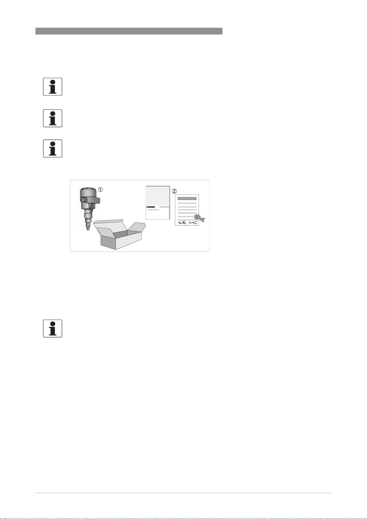
Figure 2-1: Scope of delivery
1 Device in the version as ordered
2 Mounting bracket
3 Documentation (test reports, factory and material certification (if ordered) and product documentation)
Optional accessories
• Gaskets
INFORMATION!
Assembly materials and tools are not part of the delivery. Use the assembly materials and tools
in compliance with the applicable occupational health and safety directives.
www.krohne.com04/2014 - 4003437201 - MA OPTIBAR PC 5060 C R01 en
11
Page 12
2 DEVICE DESCRIPTION
2.2 Device description
The OPTIBAR PC 5060 C is suited to applications in virtually all areas of industry. It is used to
measure the following types of pressure:
• Gauge pressure
• Absolute pressure
• Vacuum
The setup of the device is carried out via the display and adjustment unit. For further information
refer to
Keypad functions
A capacitive ceramic sensor element is used in the measuring cell.
The measuring device is supplied ready for operation. The factory settings for the process data
correspond to your order specifications.
For safety reasons do not exceed the measuring range or permissible process pressure. This
also applies when, based on the order, a measuring cell is installed with a higher measuring
range than the permissible pressure range of the process connection.
on page 41.
OPTIBAR PC 5060 C
2.2.1 Device design
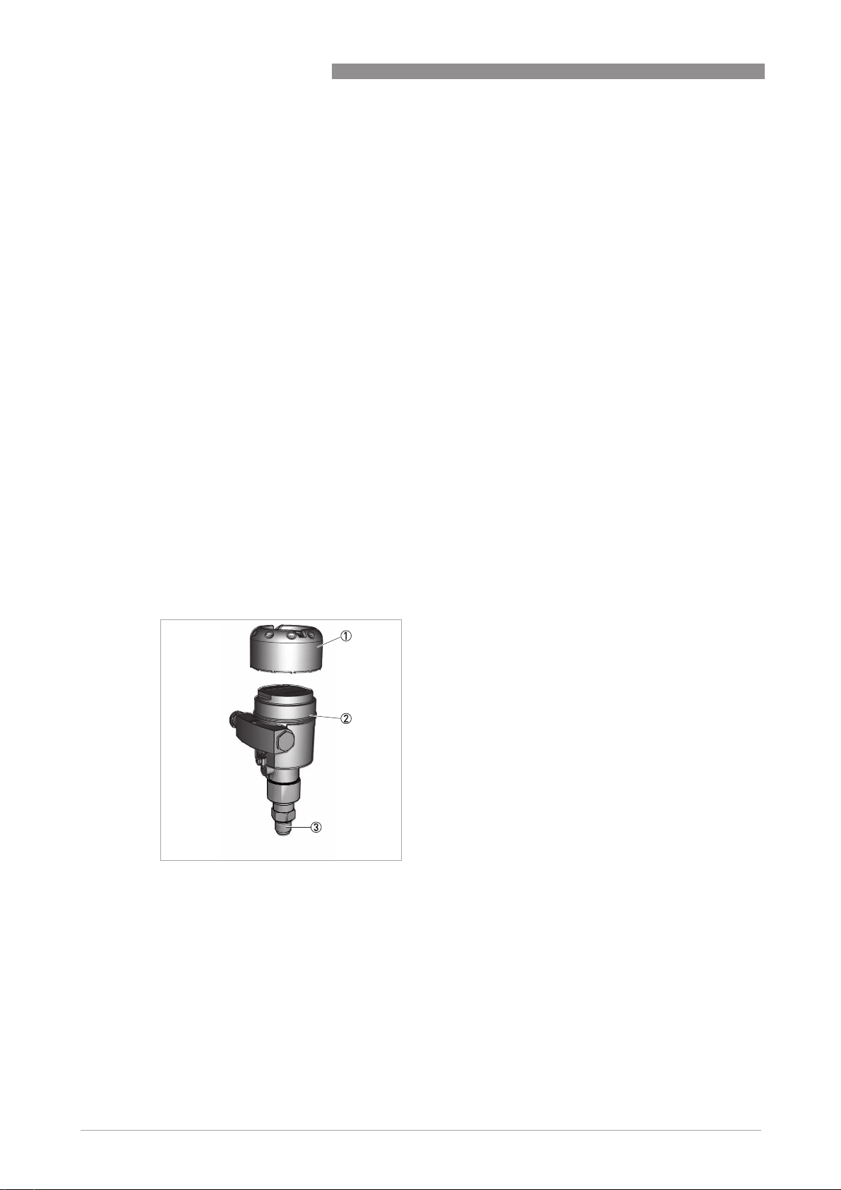
The following drawing shows the basic components of the pressure transmitter.
Figure 2-2: Basic components of single chamber pressure transmitter
1 Housing cover, optional with display and adjustment module below
2 Housing with electronics
3 Process assembly with measuring cell
12
www.krohne.com 04/2014 - 4003437201 - MA OPTIBAR PC 5060 C R01 en
Page 13
OPTIBAR PC 5060 C
Figure 2-3: Basic components of double chamber pressure transmitter
1 Housing cover
2 Housing with electronics
3 Process assembly with measuring cell
4 Housing cover, optional with display and adjustment module below
5 Operating and display module
DEVICE DESCRIPTION 2
2.3 Nameplates
INFORMATION!
Look at the device nameplate to ensure that the device is delivered according to your order.
Check for the correct supply voltage printed on the nameplate.
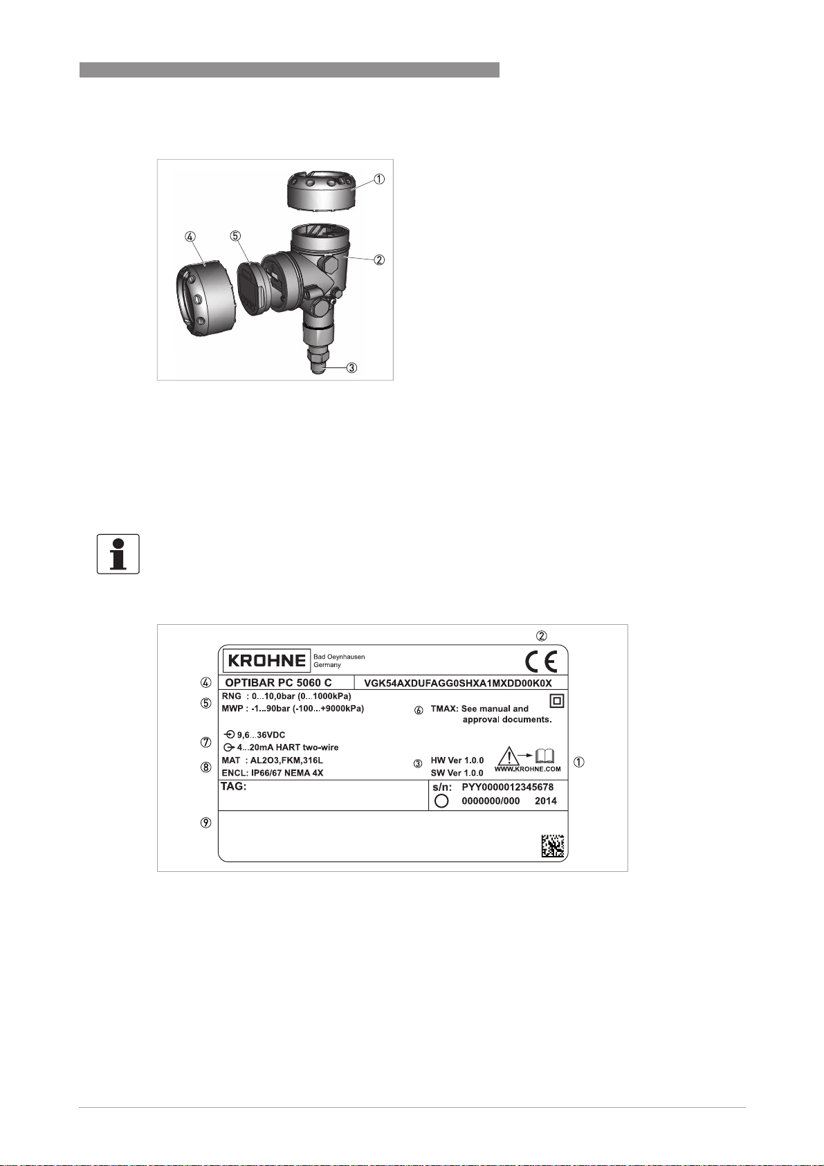
Figure 2-4: Example for nameplate for a OPTIBAR * 5060
1 Observe the installation and operating instructions
2 CE marking and marking of notified body
3 Hardware and Software version
4 Product name and type code
5 Nominal range
Permissible process pressure
6 Permissible temperature range
7 Electronics power supply and signal output
8 Ingress protection and material of wetted parts
(Diaphragm, process connections, gasket and fill fluid)
9 Approvals and approval guidelines
www.krohne.com04/2014 - 4003437201 - MA OPTIBAR PC 5060 C R01 en
13
Page 14

2 DEVICE DESCRIPTION
2.4 Terms and abbreviations
The following terms and abbreviations are used in this document.
URL
URL
URLURL
Upper Range Limit
LRL
LRL
LRLLRL
Lower Range Limit
URV
URV
URVURV
Upper Range Value
LRV
LRV
LRVLRV
Lower Range Value
SPAN
SPAN
SPANSPAN
Span
CAL SPAN
CAL SPAN
CAL SPANCAL SPAN
calibrated Span
TD
TD
TDTD
Turn Down
The following applies: URV ≤ URL, CAL SPAN ≤ SPAN, TD ≥ 1
Example: URL
Upper measuring range limit. Also called nominal range. The highest value that
can be measured by a particular device.
Lower measuring range limit. The lowest value that can be measured by a
particular device.
The calibrated measuring range or the highest adjusted measured value. This
value corresponds to the 20 mA signal.
The calibrated measuring range or the lowest adjusted measured value. This
value corresponds to the 4 mA signal.
Span or measuring range. SPAN = URL – LRL
Calibrated or adjusted measuring span. CAL SPAN = URV – LRV. Also called
"cSPAN".
This is the span set to the 4…20 mA output.
The ratio from the measuring span to the adjusted measuring span.
TD= SPAN/(CAL SPAN)= (+URL)/(CAL SPAN)
URL= 3 bar
URLURL
LRL
LRL= 0 bar
LRLLRL
URV
URV= 2 bar
URVURV
LRV
LRV= 0.5 bar
LRVLRV
OPTIBAR PC 5060 C
SPAN
SPAN= 3 bar
SPANSPAN
CAL SPAN
CAL SPAN= 1.5 bar TD
CAL SPANCAL SPAN
TD= 2:1
TDTD
14
www.krohne.com 04/2014 - 4003437201 - MA OPTIBAR PC 5060 C R01 en
Page 15
OPTIBAR PC 5060 C
2.5 Sealing concept
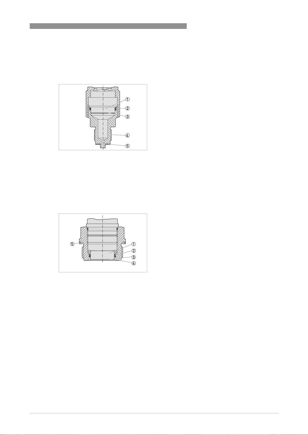
2.5.1 Sealing concept for recessed installation
Figure 2-5: Recessed installation of the CERTEC® measuring cell
1 Measuring cell
2 Measuring cell seal
3 Process diaphragm
4 Process connection
5 Seal for the process connection (optional)
DEVICE DESCRIPTION 2
2.5.2 Sealing concept for flush mounted installation with single seal
Figure 2-6: Flush mounted installation of the CERTEC® measuring cell
1 Measuring cell
2 Measuring cell seal
3 Process diaphragm
4 Process connection
5 Seal for the process connection (optional)
www.krohne.com04/2014 - 4003437201 - MA OPTIBAR PC 5060 C R01 en
15
Page 16
2 DEVICE DESCRIPTION
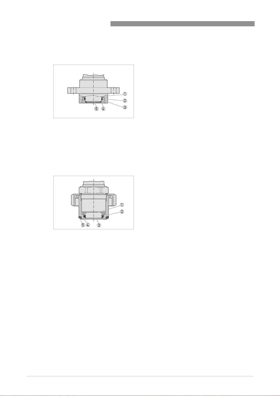
2.5.3 Sealing concept for flush mounted installation with double seal
Figure 2-7: Flush mounted installation of the CERTEC® measuring cell with double seal
1 Measuring cell
2 Measuring cell seal
3 Process diaphragm
4 Process connection
5 Additional front measuring cell seal
2.5.4 Sealing concept for hygienic installation
OPTIBAR PC 5060 C
Figure 2-8: Hygienic installation of the CERTEC® measuring cell
1 Measuring cell
2 Measuring cell moulded seal
3 Process diaphragm
4 Process connection
5 Gap-free seal for process connection
16
www.krohne.com 04/2014 - 4003437201 - MA OPTIBAR PC 5060 C R01 en
Page 17

OPTIBAR PC 5060 C
3.1 General notes on installation
INFORMATION!
Inspect the packaging carefully for damages or signs of rough handling. Report damage to the
carrier and to the local office of the manufacturer.
INFORMATION!
Do a check of the packing list to make sure that you have all the elements given in the order.
INFORMATION!
Look at the device nameplate to ensure that the device is delivered according to your order.
Check for the correct supply voltage printed on the nameplate.
3.2 Protection category of the housing
The housing of the differential pressure transmitter fulfills the requirements for ingress
protection in accordance with IEC 60529. Housing for protection category IP69K in accordance
with ISO 20653 is also available. For further information refer to
INSTALLATION 3
Technical data
on page 59.
CAUTION!
The first digit stands for the protection of the inner electronic components against the ingress of
foreign bodies including dust. The first digit "6" means that the housing is dust-proof. The
second digit designates the protection of the inner electronic components against the ingress of
water. The second digit "6" means that the housing is waterproof and also resistant against a
strong jet of water resists. The number "7" means that the case is waterproof even under water
for a given pressure and time. The number "8" means that the housing is permanently
waterproof even under water.
3.3 Packaging
CAUTION!
Devices for oxygen applications are sealed in PE foil and provided with a label "Oxygen! Use no
Oil". Remove this foil just before mounting the device! After removing the protection for the
process connection the label OOOO
grease and dirt should be avoided. Danger of explosion!
Your device was protected by packaging during transport. Its capacity to handle normal loads
during transport is assured by a test following ISO 22248. The packaging of standard devices
consists of environmentally friendly, recyclable cardboard and PE foil. For special versions, PE
foam or PE foil is also used. Dispose of the packaging material via specialised recycling
companies.
will be visible on the process connection. Penetration of oil,
2222
www.krohne.com04/2014 - 4003437201 - MA OPTIBAR PC 5060 C R01 en
17
Page 18

3 INSTALLATION
3.4 Storage
CAUTION!
Observe the storage information found on the packaging. Labels on the original packaging must
always remain legible and may not be damaged.
• Store the device in a dry and dust-free location.
• Avoid lasting direct exposure to the sun.
• Store the device in the original packaging supplied.
• Do not expose to aggressive media.
• Avoid mechanical shocks.
• Storage temperature of -40 to +80°C / -40 to +176°F.
• Relative air humidity of 20 to 85%.
3.5 Transport
• Use original packaging for transport and ensure that the packaging does not get crushed or
damaged by sharp objects or other boxes.
• Do not throw or drop the device.
• Avoid temperatures below -40°C / -40°F and above +80°C / +176°F.
• When transporting by ship, use seaworthy outer packing.
OPTIBAR PC 5060 C
3.6 Installation specifications
INFORMATION!
Observe the relevant directives, ordinances, standards and accident prevention regulations (e.g.
VDE/VDI 3512, DIN 19210, VBG, Elex V, etc.).
Ensure that all of the parts in the process are suitable for the current process conditions. This
includes in particular:
• Parts active in the measurement
• Process connection
• Process seal
Process conditions include in particular:
• Process pressure
• Process temperature
• Chemical properties of the media
• Abrasion and mechanical impact
18
www.krohne.com 04/2014 - 4003437201 - MA OPTIBAR PC 5060 C R01 en
Page 19
OPTIBAR PC 5060 C
3.7 Mounting
CAUTION!
•
Prior to installing the pressure transmitter, it is essential to verify whether the version of the
device on hand completely fulfils the technical and safety requirements of the measuring
point. This applies in particular to the measuring range, overpressure resistance,
temperature, explosion protection and operating voltage.
•
Check the materials used for the wetted parts (e.g. gasket, process connection, separating
diaphragm etc.) for suitability as regards process compatibility.
3.7.1 Rotating the housing
The transmitter housing can be rotated 350° for better readability of the display or access to the
wiring. A stop prevents the housing from being rotated too far.
• On all 2 chamber housings, the locking screw must first be loosened at the neck of the
housing.
i The housing can then be rotated to the desired position.
• Once the desired position is reached, the locking screw is tightened again.
INSTALLATION 3
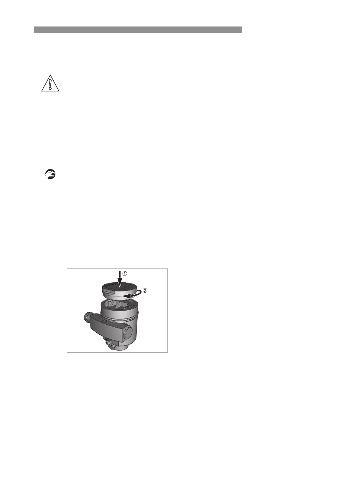
3.7.2 Mounting the display and adjustment module
The optional display and adjustment module can be set in any one of four different positions at
90° intervals. The installation of the adjustment module is carried out as per the illustrations
below. To do so, unscrew the housing cover and insert the adjustment module clockwise. The
display can be installed rotated at 90°. It is not necessary to interrupt the power supply.
Figure 3-1: Installation in single chamber housing
1 Insert the display and adjustment module into the housing
2 Turn the display and adjustment module clockwise
www.krohne.com04/2014 - 4003437201 - MA OPTIBAR PC 5060 C R01 en
19
Page 20
3 INSTALLATION
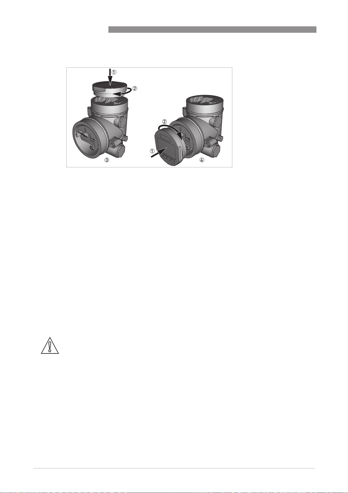
Figure 3-2: Installation in double chamber housing
1 Insert the display and adjustment module into the housing
2 Turn the display and adjustment module clockwise
3 Mounting on top
4 Mounting at side
OPTIBAR PC 5060 C
3.7.3 Temperature limits
Higher process temperatures often mean also higher ambient temperatures for electronics and
connection cables. Make sure that the upper temperature limits for the environment of the
electronics housing and connection cable are not exceeded. For further information refer to
Technical data
on page 59.
3.8 Instructions for oxygen applications
Oxygen and other gases can be explosive when brought into contact with oils, grease and
plastics, so the following measures must also be taken:
• All components of the plant, such as e.g. measuring devices must be cleaned according to the
requirements of BAM (DIN 19247).
• Depending on the seal material, certain temperatures and pressures must not be exceeded
in oxygen applications, refer to
CAUTION!
Devices for oxygen applications are sealed in PE foil and provided with a label "Oxygen! Use no
Oil". Remove this foil just before mounting the device! After removing the protection for the
process connection the label OOOO
grease and dirt should be avoided. Danger of explosion!
Technical data
will be visible on the process connection. Penetration of oil,
2222
on page 59.
20
www.krohne.com 04/2014 - 4003437201 - MA OPTIBAR PC 5060 C R01 en
Page 21
OPTIBAR PC 5060 C
3.9 Venting
CAUTION!
The filter element causes a delayed pressure equalisation when the housing cover is opened or
closed quickly. During the process the measurement can change by up to 15 mbar for up to 5
seconds.
CAUTION!
In order to ensure effective ventilation, the filter element must be always free of deposits.
CAUTION!
Do not use a high-pressure cleaner to clean the housing. The filter element may become
damaged and as a result moisture can penetrate into the housing. The exception to this is the
IP69K single chamber housing.
The ventilation for the electronics housing is assured via a filter element in the vicinity of the
cable glands, which is permeable to air but water-absorbent.
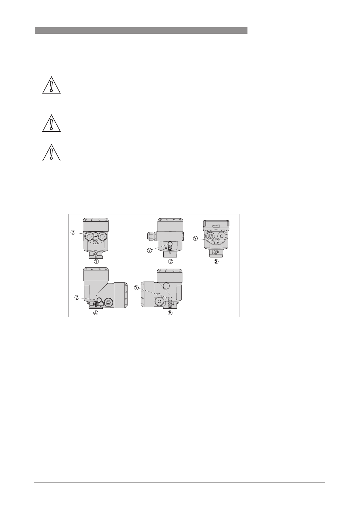
INSTALLATION 3
Figure 3-3: Venting in non-Ex, Ex ia and Ex d ia versions
1 Single chamber housing, plastic, stainless steel precision casting
2 Single chamber housing, aluminium
3 Single chamber housing, electro-polished stainless steel
4 Double chamber housing, plastic
5 Double chamber housing, aluminium
6 Filter element
The following devices feature a dummy plug instead of a filter element:
• Devices in the IP 66 / IP 68 (1bar) protection category - venting via capillary tube in
permanently connected cable
• Devices with absolute pressure
www.krohne.com04/2014 - 4003437201 - MA OPTIBAR PC 5060 C R01 en
21
Page 22
3 INSTALLATION
Devices in Ex d version
Figure 3-4: Ventilation Ex-housing
1 Single chamber housing, aluminium and stainless steel precision casting
2 Double chamber housing, aluminium and stainless steel precision casting
3 Rotating metal ring
4 Filter element
The filter element is integrated into the sensor assembly via a rotating metal ring. Align the
metal ring towards the bottom to better protect the filter element from deposits. Devices with
absolute pressure feature a dummy plug instead of a filter element.
OPTIBAR PC 5060 C
Devices with second process barrier
Figure 3-5: Ventilation gas-proof feedthrough
1 Filter element
For devices with a second process barrier, the sensor assembly is completely encased by an
additional, gas-proof feedthrough. Additional venting is not required for absolute pressure
sensors. With relative pressure sensors, the ambient pressure is measured and compensated by
an additional sensor in the electronics.
22
www.krohne.com 04/2014 - 4003437201 - MA OPTIBAR PC 5060 C R01 en
Page 23
OPTIBAR PC 5060 C
INSTALLATION 3
Devices in IP69K version
Figure 3-6: Ventilation IP69K
Filter element
Devices with absolute pressure feature a dummy plug instead of a filter element.
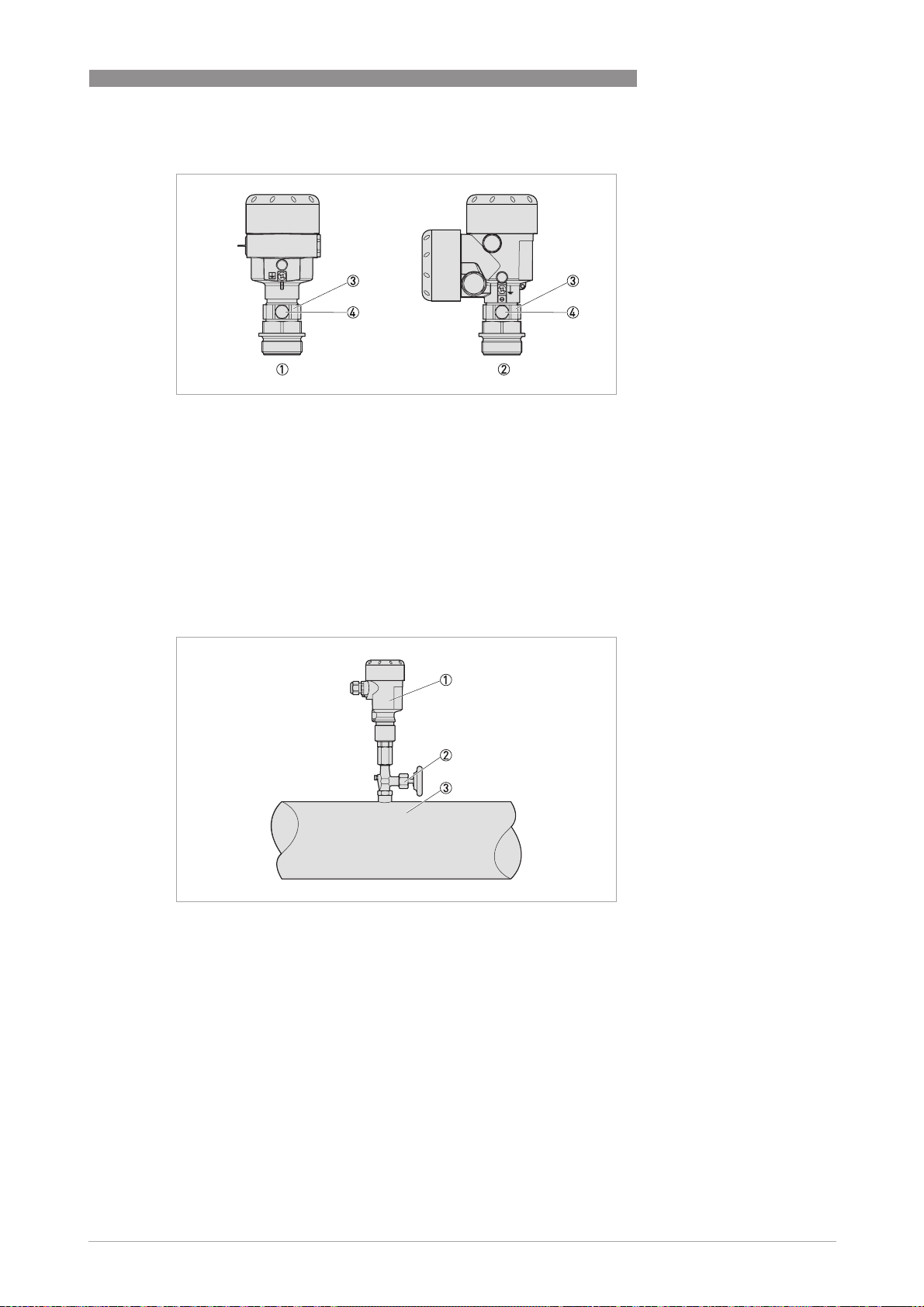
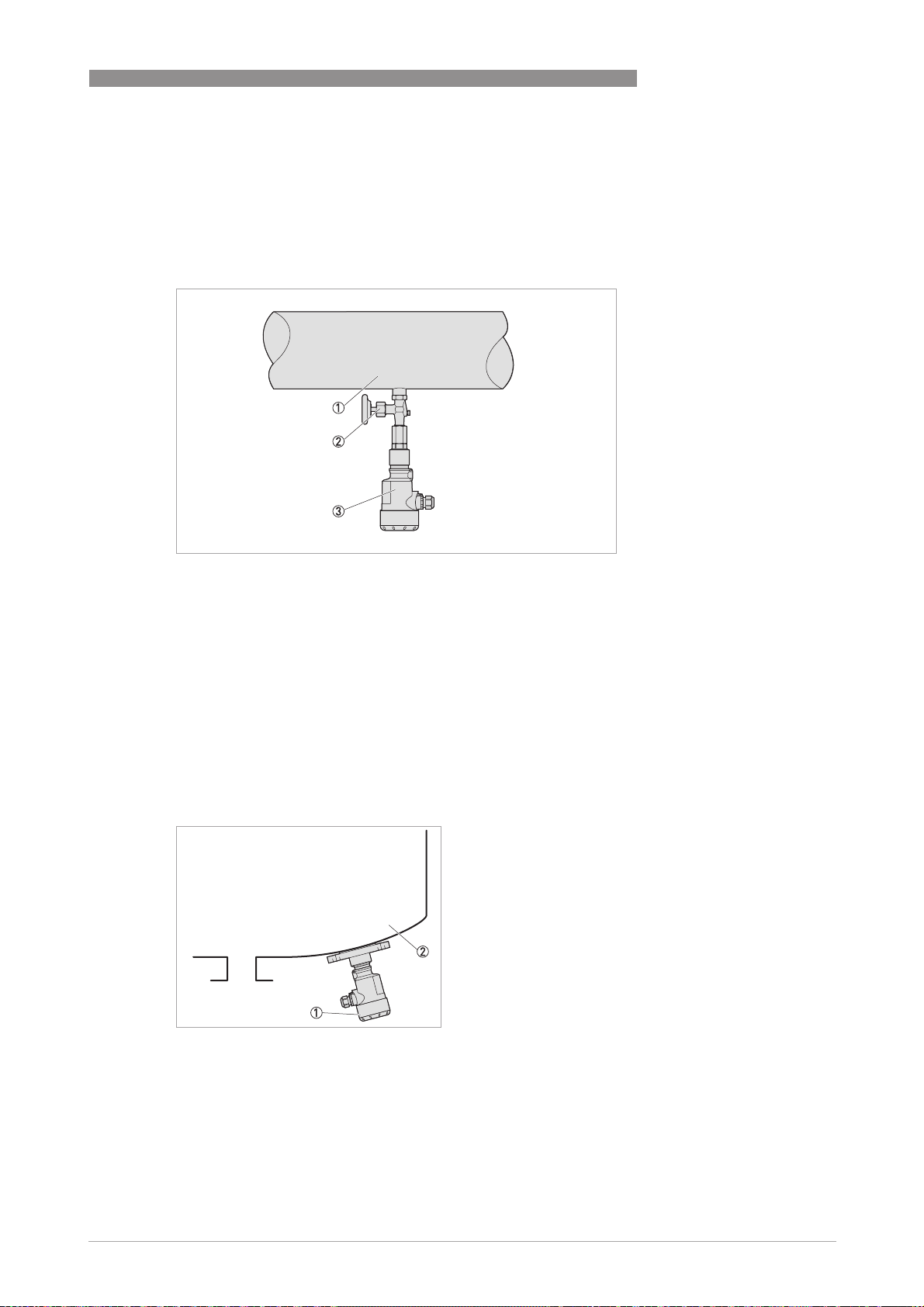
3.10 Measurement setup for process pressure measurement
The following points should be observed in this application:
• The signal converter must be mounted above the measuring point.
Figure 3-7: Measurement setup for measuring the process pressure of gases
1 Pressure transmitter
2 Shut-off valve
3 Tapping point
www.krohne.com04/2014 - 4003437201 - MA OPTIBAR PC 5060 C R01 en
23
Page 24
3 INSTALLATION
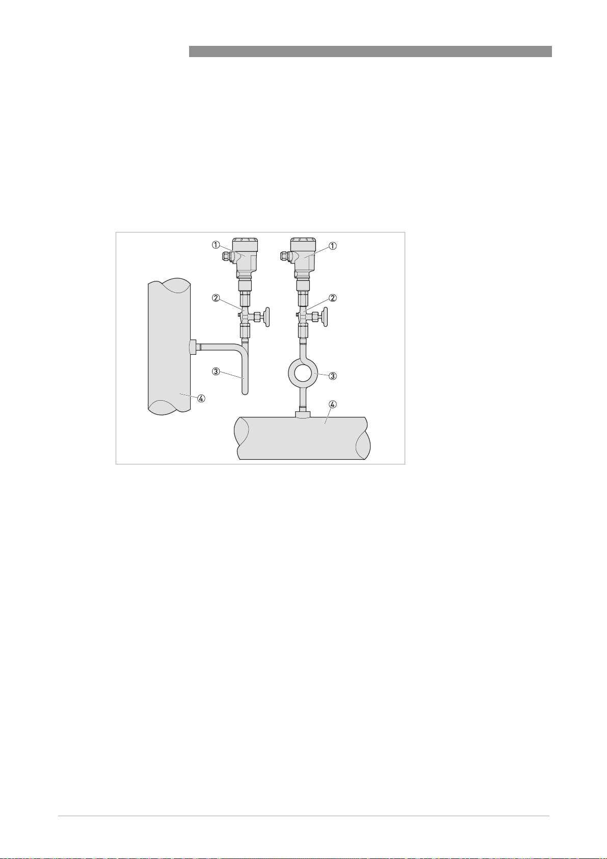
3.11 Measurement setup for steam measurement
The following points should be observed in this application:
• The pressure transmitter should be connected via a siphon to protect the measuring cell
from non-permitted high temperatures.
• Siphon to be kept free of insulation.
• When using superheated steam, the siphon must be filled with water prior to start-up.
OPTIBAR PC 5060 C
Figure 3-8: Measurement setup for steam measurement
1 Pressure transmitter
2 Shut-off valve
3 Siphon
4 Tapping point
24
www.krohne.com 04/2014 - 4003437201 - MA OPTIBAR PC 5060 C R01 en
Page 25
OPTIBAR PC 5060 C
3.12 Measurement setup for liquid measurement
The following points should be observed in this application:
• The signal converter must be mounted below the measuring point.
INSTALLATION 3
Figure 3-9: Measurement setup for liquid measurement
1 Tapping point
2 Shut-off valve
3 Pressure transmitter
3.13 Measurement setup for level measurement
The following points should be observed in this application:
• The pressure transmitter should be mounted below the lowest level.
• The pressure transmitter should be protected from filling/emptying current and agitator
surges when mounted.
Figure 3-10: Measurement setup for level measurement
1 Pressure transmitter
2 Tank
www.krohne.com04/2014 - 4003437201 - MA OPTIBAR PC 5060 C R01 en
25
Page 26
3 INSTALLATION
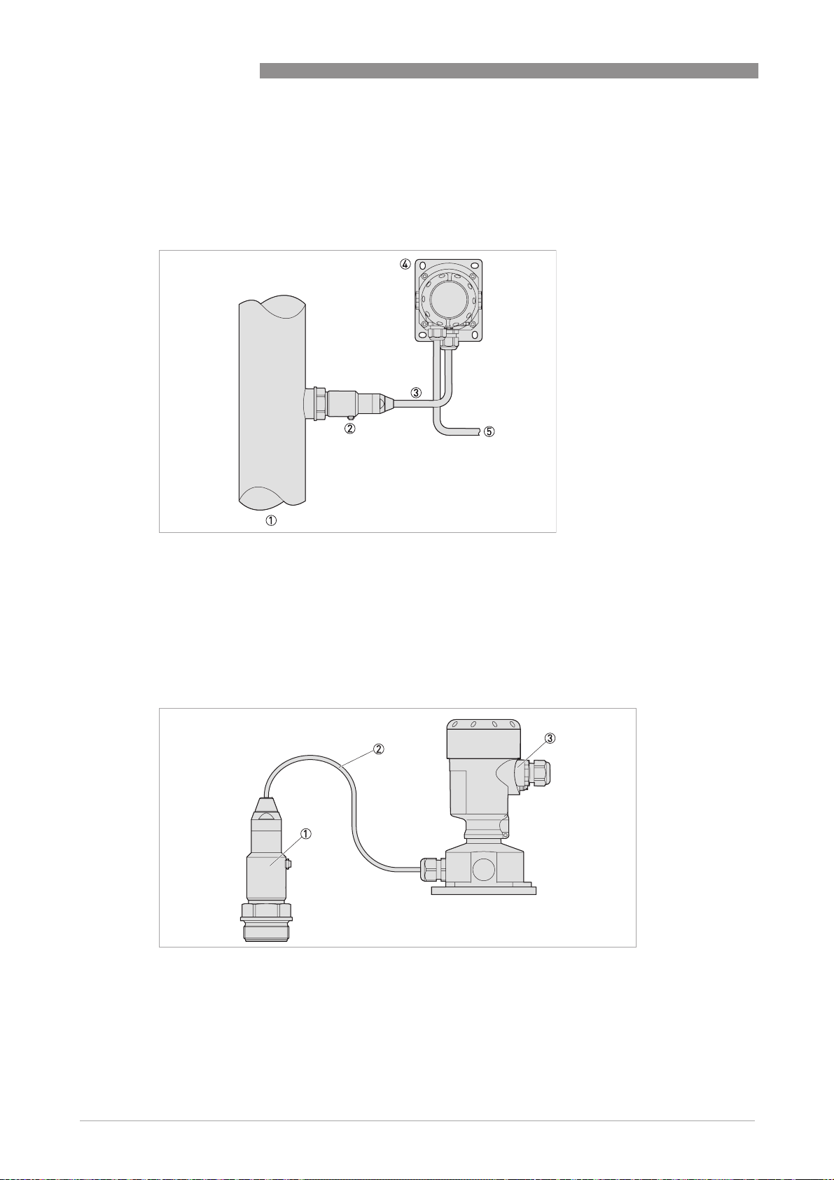
3.14 External housing
A mounting plate is available as an option to facilitate the mounting of the external housing. For
further information refer to
Technical data
OPTIBAR PC 5060 C
on page 59.
Figure 3-11: Measurement setup with an external housing
1 Tapping point
2 Sensor assembly
3 Connecting cable
4 External housing
5 Signal cable
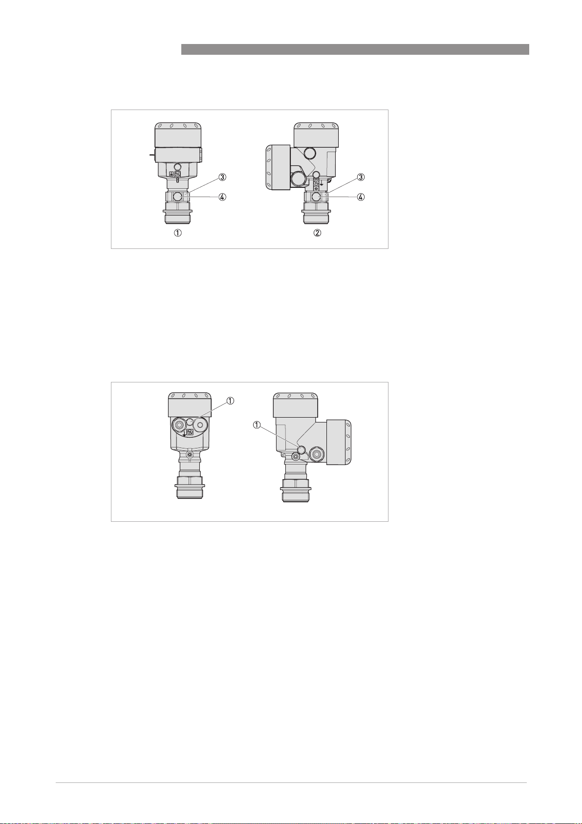
IP 68 version (25 bar)
26
Figure 3-12: Process assembly
1 Sensor assembly
2 Connection cable
3 External housing
www.krohne.com 04/2014 - 4003437201 - MA OPTIBAR PC 5060 C R01 en
Page 27

OPTIBAR PC 5060 C
Figure 3-13: External housing (IP 68)
Electronic insert
Cable gland for the power supply
Cable gland for the sensor connection cable
INSTALLATION 3
www.krohne.com04/2014 - 4003437201 - MA OPTIBAR PC 5060 C R01 en
27
Page 28
4 ELECTRICAL CONNECTIONS
4.1 Safety instructions
DANGER!
All work on the electrical connections may only be carried out with the power disconnected. Take
note of the voltage data on the nameplate!
DANGER!
Observe the national regulations for electrical installations!
WARNING!
Observe without fail the local occupational health and safety regulations. Any work done on the
electrical components of the measuring device may only be carried out by properly trained
specialists.
INFORMATION!
Look at the device nameplate to ensure that the device is delivered according to your order.
Check for the correct supply voltage printed on the nameplate.
OPTIBAR PC 5060 C
4.2 Notes for electrical cables
DANGER!
The device must be grounded to a spot in accordance with regulations in order to protect
personnel against electric shocks.
DANGER!
Cables may only be connected when the power is switched off! Since the transmitter has no
switch-off elements, overcurrent protection devices, lightning protection and/or energy isolating
devices must be provided by the customer.
28
www.krohne.com 04/2014 - 4003437201 - MA OPTIBAR PC 5060 C R01 en
Page 29

OPTIBAR PC 5060 C
ELECTRICAL CONNECTIONS 4
4.2.1 Requirements for signal cables provided by the customer
If the signal cable was not ordered, it is to be provided by the customer. The following
requirements regarding the electrical specifications of the signal cable must be observed:
Specifications for standard signal cables
• Test voltage: ≥ 500 VAC RMS (750 VDC)
• Temperature range: -40...+105°C / -40...+221°F
• Capacity: ≤ 200 pF/m / 61 pF/ft
• Inductance: ≤ 0.7 µH/m / 0.2 µH/ft
• Use cable with round cross section.
• A cable outer diameter of 5…9 mm / 0.2 … 0.35" ensures the seal effect of the cable gland. If
you are using cable with a different diameter or cross-section, exchange the seal or use a
suitable cable gland.
• We generally recommend the use of a shielded cable for HART
4.2.2 Laying electrical cables correctly
®
multidrop mode.
Figure 4-1: Protect housing from dust and water
1 Lay the cable in a loop just before the housing.
2 Tighten the screw connection of the cable entry securely.
3 Never mount the housing with the cable entries facing upwards.
4 Seal cable entries that are not needed with a plug.
www.krohne.com04/2014 - 4003437201 - MA OPTIBAR PC 5060 C R01 en
29
Page 30

4 ELECTRICAL CONNECTIONS
4.2.3 Cable preparation
The device is connected with standard two-wire cable without shielding. If electromagnetic
interference is expected which is above the test values of EN 61326-1 for industrial areas, a
shielded cable should be used.
Check which outer diameter is suitable for the cable gland in order to ensure the sealing effect
according to the specified IP protection class.
• 5...9 mm / 0.20...0.35" (standard)
• 6...12 mm / 0.24...0.47" (optional)
• 10...14 mm / 0.40...0.55" (optional)
The terminals in the terminal compartment are designed for wire cross-sections of up to
1.5 mm². To ensure a proper connection, you should strip the cable 40…50 mm / 1.6...2".
OPTIBAR PC 5060 C
Figure 4-2: Stripping the cable
1 40...50 mm / 1.6...2"
2 5mm/ 0.2"
30
www.krohne.com 04/2014 - 4003437201 - MA OPTIBAR PC 5060 C R01 en
Page 31

OPTIBAR PC 5060 C
4.2.4 Cable entry 1/2-14 NPT (female)
With plastic housings, the NPT cable gland or the conduit steel tube must be screwed without
grease into the thread. For further information about max. torque for all housings refer to
Technical data
on page 59.
4.2.5 Connector pin assignment
Figure 4-3: Connector M12 x 1, 4-pin
1 VS+
2 Not connected
3 Not connected
4 VS-
ELECTRICAL CONNECTIONS 4
Contact pin Colour of cable Electronic insert for terminal
Pin 1 Brown 1
Pin 4 Blue 2
Figure 4-4: 7/8 connector, Foundation Fieldbus (FF)
1 VS-
2 VS+
3 Not connected
4 Cable shield
Contact pin Colour of cable Electronic insert for terminal
Pin 1 Blue 1
Pin 2 Brown 2
Pin 4 Green / yellow Grounding
www.krohne.com04/2014 - 4003437201 - MA OPTIBAR PC 5060 C R01 en
31
Page 32

4 ELECTRICAL CONNECTIONS
Figure 4-5: Connector, Harting HAN 8D (left) and Harting HAN 7D (right)
1 VS-
2 VS+
Contact pin Colour of cable Electronic insert for terminal
Pin 1 Black 1
Pin 2 Blue 2
Pin 8 Green / yellow Grounding
OPTIBAR PC 5060 C
4.2.6 Connection to the power supply
Figure 4-6: Connection to the power supply
1 Red
2 Black
3 Power supply with load
32
www.krohne.com 04/2014 - 4003437201 - MA OPTIBAR PC 5060 C R01 en
Page 33

OPTIBAR PC 5060 C
4.2.7 Cable shield and grounding
If a shielded cable is necessary, connect the cable shield on both ends to the grounding potential.
In the device, the cable shield must be connected directly to the internal ground terminal.
The ground terminal outside on the housing must be connected to the grounding potential with
low impedance.
DANGER!
In hazardous areas, the grounding is carried out according to the installation instructions.
CAUTION!
Significant potential differences exist inside galvanization plants as well as on vessels with
cathodic corrosion protection. A two-sided shield grounding can cause unacceptably high shield
currents as a result.
CAUTION!
The metallic and wetted parts (process connection, cap flange, measuring cell and separating
diaphragm etc.) are conductive connected with the inner and outer ground terminal on the
housing.
ELECTRICAL CONNECTIONS 4
www.krohne.com04/2014 - 4003437201 - MA OPTIBAR PC 5060 C R01 en
33
Page 34

4 ELECTRICAL CONNECTIONS
4.3 Electrical connection
The connection of the power supply and the signal output is carried out via spring-loaded
terminals in the housing. The display and adjustment module is connected via contact pins with
the interface adapter.
4.3.1 Connection in the terminal compartment
OPTIBAR PC 5060 C
Figure 4-7: Terminal compartment from above
Procedure
• Unscrew the housing cover.
• If present, remove the display and adjustment module by turning it to the left.
• Loosen union nut of the cable gland.
• For preparation of connection cable refer to
• Push the cable through the cable gland into the terminal compartment.
• Insert the wire ends into the open terminals according to the wiring plan. Flexible cores with
cable end sleeves as well as solid cores can be inserted directly into the terminal openings. In
case of flexible cores, press the spring terminal with a small screwdriver to open the terminal
opening.
• Check the proper hold of the wires in the terminals by lightly pulling on them.
• Connect the cable shield to the internal ground terminal, connect the outer ground terminal to
the customer/plant equipotential bonding.
• Tighten the union nut of the cable gland. The sealing ring must completely enclose the cable.
• Screw the housing cover back on.
Cable preparation
on page 30.
34
www.krohne.com 04/2014 - 4003437201 - MA OPTIBAR PC 5060 C R01 en
Page 35

OPTIBAR PC 5060 C
ELECTRICAL CONNECTIONS 4
4.3.2 Connection in the housing base (external housing)
Figure 4-8: Terminal box from front
1 Brown
2 Blue
3 Yellow
4 White
5 Shielding
6 Pressure equalisation capillary
Procedure
• Unscrew the housing cover
• If present, remove the display and adjustment module by turning it to the left
• Loosen union nut of the cable gland
• For preparation of connection cable refer to
Cable preparation
• Push the cable through the cable gland into the terminal compartment
• Insert the wire ends into the open terminals according to the wiring plan. Solid cores as well
as flexible cores with cable end sleeves can be inserted directly into the terminal openings. In
case of flexible cores, press the spring terminal with a small screwdriver to open the terminal
opening.
• Check the hold of the wires in the terminals by lightly pulling on them
• Connect the cable shield to the internal ground terminal, connect the outer ground terminal to
the equipotential bonding
• Tighten the union nut of the cable gland. The sealing ring must completely enclose the cable
• Screw the housing cover back on
on page 30
www.krohne.com04/2014 - 4003437201 - MA OPTIBAR PC 5060 C R01 en
35
Page 36

4 ELECTRICAL CONNECTIONS
4.3.3 Single chamber housing
DANGER!
For devices used in hazardous areas, additional safety notes apply; please refer to the Ex
documentation.
The following illustration applies to both the non-Ex as well as the Ex ia, the Ex d and the Ex d ia
version.
Electronics compartment
OPTIBAR PC 5060 C
1 Power supply / signal output
2 Interface adapter for the display and adjustment module
3 Digital interface
4 Ground terminal for connection of the cable shield
36
www.krohne.com 04/2014 - 4003437201 - MA OPTIBAR PC 5060 C R01 en
Page 37

OPTIBAR PC 5060 C
4.3.4 Double chamber housing
DANGER!
For devices used in hazardous areas, additional safety notes apply; please refer to the Ex
documentation.
The following illustration applies to both the non-Ex as well as the the Ex ia, and the Ex d version.
Electronics compartment
ELECTRICAL CONNECTIONS 4
1 Internal connection to terminal compartment
2 Interface adapter for the display and adjustment module
Terminal compartment
1 Power supply / signal output
2 Interface adapter for the display and adjustment module
3 Ground terminal for connection of the cable shield
www.krohne.com04/2014 - 4003437201 - MA OPTIBAR PC 5060 C R01 en
37
Page 38

4 ELECTRICAL CONNECTIONS
4.3.5 Double chamber housing Ex d ia
DANGER!
For devices used in hazardous areas, additional safety notes apply; please refer to the Ex
documentation.
Electronics compartment
1 Power supply / signal output
2 Interface adapter for the display and adjustment module
3 Digital interface
OPTIBAR PC 5060 C
Terminal compartment
1 Power supply / signal output
2 Ground terminal for connection of the cable shield
38
www.krohne.com 04/2014 - 4003437201 - MA OPTIBAR PC 5060 C R01 en
Page 39

OPTIBAR PC 5060 C
4.4 Grounding the measuring device
WARNING!
Within galvanic plants as well as vessels with cathodic corrosion protection there are
considerable potential differences. Considerably equipotential bonding currents can be caused
via the cable shield when the shield is grounded on both ends. To avoid this, the cable shield
must only be connected to the grounding potential on one side of the control cabinet in such
applications. The cable shield must not be connected to the internal ground terminal in the
device and the outer ground terminal on the housing not to the equipotential bonding!
CAUTION!
The metallic and wetted parts (process connection, cap flange, measuring cell and separating
diaphragm etc) are conductive connected with the inner and outer ground terminal on the
housing.
If a shielded cable is necessary, connect the cable shield on both ends to the grounding potential.
In the signal converter, the cable shield must be connected directly to the internal ground
terminal. The ground terminal outside on the housing must be connected to the equipotential
bonding with low impedance. If equipotential bonding currents are expected, the evaluation side
must be connected with a ceramic capacitor (e.g. 1 nF, 1500 V). The low frequency equipotential
bonding currents are thus suppressed, but the protective effect against high frequency
interference signals remains.
ELECTRICAL CONNECTIONS 4
4.5 Description of the current output
The current output is a 2-wire 4…20 mA output with a low alarm of 3.6 mA and high alarm of
21 mA set by default. A high frequency HART
information on the current output, refer to
®
signal superimposes this signal. For further
Technical data
on page 59.
www.krohne.com04/2014 - 4003437201 - MA OPTIBAR PC 5060 C R01 en
39
Page 40

5 START-UP
5.1 Start-up
The pressure transmitter may only be started up after it has been completely installed and
checked by appropriately qualified personnel. Switch on the operating voltage for start-up. Prior
to applying the operating voltage, it is essential to check the correctness of the process
connection and the electrical connection and ensure that the impulse line has been completely
filled with the process medium. Then proceed with start-up.
Prior to applying the operating voltage check that
1. the process connection fits properly
2. the signal and, if necessary, supply lines are properly connected
3. the impulse lines are completely filled with the process medium
After connecting the differential pressure transmitter to the power supply or after voltage
recovery, the device performs a self test for approximately 10 seconds.
Self test routine
1. Internal check of the electronics.
2. Indication of the device type, hardware and software version as well as the measurement loop
name on the display or PC.
3. Indication of a status message on the display or PC.
4. Output signal jumps to the set alarm current.
5. After that the current measuring value is outputted to the signal cable.
OPTIBAR PC 5060 C
40
www.krohne.com 04/2014 - 4003437201 - MA OPTIBAR PC 5060 C R01 en
Page 41

OPTIBAR PC 5060 C
5.2 Keypad functions
INFORMATION!
The device can be configured either via the relevant fieldbus or the adjustment module.
The display and adjustment module is used for indication of measuring values, adjustment and
diagnosis.
START-UP 5
1 LCD display
2 Function buttons
The device is operated via the four keys of the display and adjustment module 2. The LC display
1 indicates the individual menu items. Approx. 60 minutes after the last pressing of a key, an
automatic reset in the indication of measuring values is triggered. Any values not confirmed with
[OK] will not be saved.
[OK]
• Move back to the menu overview
• Confirm selected menu
• Editing the parameters
• Store value
[Z]
• Change measured value
• Select list entry
• Select editing position
[+]
• Change value of the parameter
[ESC]
• Cancel entry
• Jump to next higher menu
www.krohne.com04/2014 - 4003437201 - MA OPTIBAR PC 5060 C R01 en
41
Page 42

5 START-UP
5.3 Quick setup
To quickly and easily adapt the device to the application, select the menu item "Quick setup".
This parameter adjustment essentially involves the selection of the application, position
correction and adjustment of the span.
In this chapter, not all settings are displayed graphically but all settings are described.
OPTIBAR PC 5060 C
1 Measurement loop name
Measurement loop name
Measurement loop nameMeasurement loop name
Assign a suitable measurement loop name
2 Adjustment units
Adjustment units
Adjustment unitsAdjustment units
Determine the adjustment and temperature units of the device.
3 Application
Application
ApplicationApplication
The selection includes process pressure and level.
Adjustment process pressure
1 Sensor mounting correction
Sensor mounting correction
Sensor mounting correctionSensor mounting correction
In this menu item you compensate the influence of the installation position of the device (offset) on the
measured value.
2 Zero
Zero
ZeroZero
In this menu item you determine the zero point of your measurement (LRV)
This value corresponds to the output signal of 4 mA.
3 Span
Span
SpanSpan
This value corresponds 100%, or rather an output signal of 20 mA (URV)
If the zero point is actually 0, this value corresponds to the measuring span.
42
www.krohne.com 04/2014 - 4003437201 - MA OPTIBAR PC 5060 C R01 en
Page 43

OPTIBAR PC 5060 C
Adjustment level
1 Sensor mounting correction
Sensor mounting correction
Sensor mounting correctionSensor mounting correction
In this menu item you compensate the influence of the installation position of the device (offset) on the
measured value.
2 Min.-adjustment
Min.-adjustment
Min.-adjustmentMin.-adjustment
Enter the (pressure) value for the min. level.
At 0% this corresponds to the output signal of 4 mA.
3 Max.-adjustment
Max.-adjustment
Max.-adjustmentMax.-adjustment
Enter the (pressure) value for the max. level.
At 100% this corresponds to the output signal of 20 mA.
5.4 Extended adjustment
The main menu is divided into five sections:
• Start-up
• Display
• Diagnosis
• Additional adjustments
• Info
START-UP 5
5.4.1 Start-up
Measurement
loop name
Application In this menu item you select the application: process pressure and level are available. The default
Units In this menu item the adjustment units, as well as the temperature unit are determined. The selection
Assign a unique device ID. This is useful or even necessary in digital systems and for monitoring large
systems.
setting is process pressure.
of the adjustment unit determines the unit displayed in the "Min-adjustment" and "Max-adjustment"
items. In "Level" mode, it is possible to carry out the adjustment in a height unit (e.g. meters). To do
so, the density of the medium must also be specified.
Adjustment units Process pressure
Temperature unit °C, °F and K
Process pressure
Process pressureProcess pressure
mbar, bar, Pa, kPa, MPa, psi, mmH2O,
mmHg, inH2O, inHg and user-defined
Level
Level
LevelLevel
Density input required:
mm, cm, m, in and ft
www.krohne.com04/2014 - 4003437201 - MA OPTIBAR PC 5060 C R01 en
43
Page 44

5 START-UP
OPTIBAR PC 5060 C
Sensor
mounting
correction
Adjustment Adjustment refers to setting the zero point (zero) and maximum measured value (span). These values
Damping For the damping of process-dependent measured value fluctuations, you can choose a suitable
Linearization A linearization is necessary for all vessels in which the vessel volume does not increase linearly with
The mounting position of the device has a great impact on the measured value (offset), especially with
small measuring ranges and isolating systems. The position correction compensates for this offset.
The position correction can automatically take on the current measured value as correction value
(auto correct). Alternatively, this correction value can also be entered manually using the "Edit"
function. Once the position has been corrected, the measured value is corrected to 0. Position
correction can compensate for a maximum of 20% of the nominal measuring range.
Offset Input in adjustment unit, automatic transfer
correspond to the values of 4 and 20 mA. If the adjustment ranges are exceeded, the message
"Outside parameter limits" is displayed.
Min.-adjustment / Zero Process pressure
Max.-adjustment / Span Process pressure
integration time. The values which can be entered are from 0 … 999 seconds with an increment of 0.1
seconds.
Integration time In 0.1 second increments
the level, e.g. in a horizontal cylindrical or spherical tank, and the indication or output of the volume is
required. Corresponding linearization curves are preprogrammed for these vessels. They represent
the correlation between the level percentage and vessel volume. By activating the appropriate curve,
the volume percentage of the vessel is displayed correctly. Enter the desired parameters using the
function buttons and save the entries. Note the following if the pressure transmitter with
corresponding approval is used as part of an overfill protection system according to WHG (Water
Resources Act): If a linearization curve is selected, the measuring signal is no longer linearly
proportional to the level. This must be taken into consideration by the user, particularly when setting
the switching point on the limit signal indicator.
of the current measured value
Process pressure
Process pressureProcess pressure
Zero in %, pressure
Level (standard 0%)
Level (standard 0%)
Level (standard 0%)Level (standard 0%)
Min. in X %, pressure or filling height
Process pressure
Process pressureProcess pressure
Span in %, pressure
Level (standard 100%)
Level (standard 100%)
Level (standard 100%)Level (standard 100%)
Min. in X %, pressure or filling height
Type of linearization Level
Current output In the current output menu, the saturation region for above or below a threshold is set. Under
Lock
adjustment /
Unlock
adjustment
"Current output min./max." these limit values can be set. The factory setting is 3.8 mA and 20.5 mA.
This corresponds to the NAMUR recommendation NE 43.
Mode Output characteristic 0...100% = 4...20 mA or
Failure mode ≤ 3.6 mA, ≥ 21 mA, last valid measured value
Min. and
Max.
In this menu item, a 4-digit PIN can be activated, which protects against undesirable or unintended
changes of the settings. With a PIN active, remote access via software or other systems is also no
longer possible.
Run now
Min. current 3.8 mA, 4 mA
Max. current 20.5 mA, 20 mA
Level
LevelLevel
Linear, Horiz.cylinder, Sphere and User
programmable
0...100% = 20...4 mA
44
www.krohne.com 04/2014 - 4003437201 - MA OPTIBAR PC 5060 C R01 en
Page 45

OPTIBAR PC 5060 C
5.4.2 Display
START-UP 5
Menu language In this menu item you can set the desired language.
Displayed value
1 and 2
Backlight A backlight on the display is available, which can be turned on or off in this menu. By default, this
Factory settings: English
German, English, French, Spanish, Portuguese, Italian, Dutch, Russian, Turkish, Polish and Czech
In this menu item you can define how the measured value should be presented on the display.
The factory setting is "Linear percent".
"Level" Filling height or Process pressure (Adjustment
units), Percent, Scaled, Current output, Linear
percent, Meas. cell temp. and Electronics
temperature
"Process pressure" Process pressure, Percent, Scaled, Current
output, Linear percent, Meas. cell temp. and
Electronics temperature
function is disabled.
Off, On
5.4.3 Diagnosis
Device status Status signals Check function, Out of Specification, Maintenance required, Failure
Peak value The respective minimum and maximum pressure values are stored in the device. Under "Peak
Simulation In menu item "Simulation", measured values can be simulated via the current output. These are
values", these values can be viewed or reset. In addition to the pressure, the minimum and maximum
values of the sensor cell and the electronics temperature is stored. These can be viewed or reset
here.
Peak value
"Process pressure"
Peak value
"Meas. cell temp."
Peak value
"Electronics temperature"
issued as both analogue and digital (via HART
minutes after the last key stroke.
For applications
"Process pressure"
For applications
"Level"
Reset peak value
Reset peak value
Reset peak value
®
). The simulation is automatically cancelled 60
Process pressure, Percent, Current output, Linear percent, Meas.
cell temp. and Electronics temperature
Filling height or Process pressure (Adjustment units), Percent,
Current output, Linear percent, Meas. cell temp. and Electronics
temperature
www.krohne.com04/2014 - 4003437201 - MA OPTIBAR PC 5060 C R01 en
45
Page 46

5 START-UP
5.4.4 Additional adjustments
OPTIBAR PC 5060 C
PIN In this menu item the PIN can be changed. This option is only available if it has been enabled under
Date / Time Internal clock setting
Reset For further information refer to
Copy instrument
settings
Special
parameters
Scaling In menu item "Scaling variable" you define the scaling variables and the scaling unit for the level
Current output In this menu item it is determined which measured variable relates to which current output. Under
"Setup - Lock adjustment". The PIN is "0000" by default factory conditions.
0000 Change PIN
Write date, time, data in device
Reset
on page 47.
Delivery status and Basic settings
For further information refer to
Copy instrument settings
Changing these settings is possible only after consultation with a service employee.
mode.
In menu item "Scaling format" you define the scaling format on the display and the scaling of the
level measurement for 0% and 100%.
Scaling variable Scaling variable
Scaling format Scaling format
"Current output - Adjustment", the current output can be assigned a corresponding measured
value.
Current output
variable
Current output,
adjustment
Saving the device settings
Scaling unit
100% corresponds - user-defined value
0% corresponds - user-defined value
For applications "Level"
Filling height or Process pressure (Adjustment units), Percent, Scaled,
Linear percent, Meas. cell temp. and Electronics temperature
For applications "Process pressure"
Process pressure, Percent, Linear percent, Meas. cell temp. and
Electronics temperature
0% = 0% or 100% = 100%
on page 48.
HART® mode The pressure transmitter offers the HART® modes "Analogue current output" and "Fix current (4
mA). Under "Fix current (4 mA)", up to 64 sensors can be operated on a two-wire multidrop mode.
Each device must be assigned a HART
mA. Under "Analogue current output", however, a 4…20 mA signal can also be issued for the
assigned HART
HART® address
Output mode
®
address in multidrop mode.
0...63
Analogue current output with HART® or Fix current (4 mA) with HART
®
address between 0 und 63. The analogue signal is fixed at 4
5.4.5 Info
Device name Device name
Serial number
Instrument version Software version
Hardware version
Factory calibration Factory calibration date
Date of last change
Sensor characteristics Order-related device characteristics
46
www.krohne.com 04/2014 - 4003437201 - MA OPTIBAR PC 5060 C R01 en
®
Page 47

OPTIBAR PC 5060 C
5.5 Reset
The reset function resets specific user entries. There are two reset functions available:
Delivery status
Delivery status
Delivery statusDelivery status
Restore the default values at the time of delivery, including the order-specific settings. A false
signal suppression, user programmable linearization curve as well as the measured value
memory will be deleted.
Basic settings
Basic settings
Basic settingsBasic settings
Reset the set data, including special parameters to the default values of the manufacturer. A
false signal suppression, user programmable linearization curve as well as the measured value
memory will be deleted.
The following menu items are affected during a reset
Menu item Parameter Default
Measurement loop name Sensor
Application No reset
Unit Adjustment units mbar (cell ≤ 400 mbar)
Sensor mounting correction 0.00 bar
Adjustment Zero / Min.-adjustment 0.00 bar - 0.00%
Damping Integration time 0.0 seconds
Current output Current output mode Output characteristic 4...20 mA
Lock adjustment Unlock
Language English
Displayed value 1 Current output in %
Displayed value 2 Meas. cell temp. in °C
Backlight Off
Simulation Process pressure
PIN 0000
Scaling Scaling variable Volume in L
HART® mode
START-UP 5
bar (cell ≥ 1 bar)
Temperature unit C°
Span / Max.-adjustment +URL in bar - 100%
Failure mode ≤ 3.6 mA
Current output variable Linear percent - Level
Current output, adjustment 0...100% = 4...20 mA
Current output min./max. Min. 3.8 mA
Max. 20.5 mA
Scaling format 0% = 0 L / 100% = 0 L
Address 0
www.krohne.com04/2014 - 4003437201 - MA OPTIBAR PC 5060 C R01 en
47
Page 48

5 START-UP
5.6 Saving the device settings
We recommended noting the parameters and archiving them afterwards. They are thus available
for multiple use or service purposes. If the pressure transmitter is equipped with a display and
adjustment module, the most important data can be read out of the sensor into the display and
adjustment module. The data remain there permanently even if the sensor power supply fails. If
it is necessary to exchange the signal converter, the display and adjustment module is inserted
into the replacement device and the data are written into the signal converter under the menu
item "Copy device data".
5.7 Diagnosis memory
The device has several internal memories which are available for diagnosis purposes. The data
remain even with voltage interruption.
Measured value memory
Measured value memory
Measured value memoryMeasured value memory
Up to 60,000 measured values can be stored in a ring memory. Each entry contains a time stamp
as well as the respective measured value. Storable values are for example:
• Process pressure
• Level
• Percent value
• Linear percent
• Scaled values
• Meas. cell temp.
• Electronic temperature
OPTIBAR PC 5060 C
With the default factory settings, the measured value memory is active and stores distance,
measurement reliability and electronics temperature every minute. The requested values and
TM
recording conditions are set via a PC with PACTware
/DTM or the control system with EDD.
48
www.krohne.com 04/2014 - 4003437201 - MA OPTIBAR PC 5060 C R01 en
Page 49

OPTIBAR PC 5060 C
Event memory
Event memory
Event memoryEvent memory
Up to 500 events are automatically stored with a time stamp in the event memory (nondeletable). Each entry contains the date/time, event type, event description and value. Event
types are for example:
• Modification of a parameter
• Switch on and shut off times
• Status message acc. to NE 107
• Error message acc. to NE 107
The data are read out via a PC with PACTware
5.8 Failures and diagnostics
The operator of the system is responsible for taking suitable measures to remove interferences.
The differential pressure transmitter offers maximum reliability. Nevertheless, faults can occur
during operation. The first measures are to evaluate the error messages, check the output
signals as well as the verification of measurement errors.
START-UP 5
TM
/DTM or the control system with EDD.
Asset Management and diagnostics acc. to NE 107
Asset Management and diagnostics acc. to NE 107
Asset Management and diagnostics acc. to NE 107Asset Management and diagnostics acc. to NE 107
The device features self-monitoring and diagnostics according to NE 107 and VDI/VDE 2650. In
addition to the status messages in the following tables there are more detailed error messages
available under the menu item "Diagnostics" via the display and adjustment module,
TM
PACTware
Status messages
Status messages
Status messagesStatus messages
/DTM and EDD.
The status messages are divided into the following categories in accordance with NE 107:
• Failure
Failure
FailureFailure
Due to a malfunction in the device, a failure message is outputted. This status message is
always active. It cannot be deactivated by the user.
• Check function
Check function
Check functionCheck function
The device is in operation, the measured value is temporarily invalid. This status message is
inactive by default. It can be activated by the user via PACTware/DTM or EDD.
• Out of specification
Out of specification
Out of specificationOut of specification
The measured value is unstable because the device specification is exceeded. This status
TM
message is inactive by default. It can be activated by the user via PACTware
• Maintenance required
Maintenance required
Maintenance requiredMaintenance required
/DTM or EDD.
Due to external influences, the device function is limited. The measurement is affected, but
the measured value is still valid. Plan in maintenance for the device because a failure is
expected in the near future. This status message is inactive by default. It can be activated by
TM
the user via PACTware
/DTM or EDD.
www.krohne.com04/2014 - 4003437201 - MA OPTIBAR PC 5060 C R01 en
49
Page 50

5 START-UP
5.8.1 Error codes
Failure
OPTIBAR PC 5060 C
Code
Cause Action or description
Text message
F013
No measurement value available
F017
Adjustment span too small
F025
Error in the linearisation table
F36
No operable sensor software
F40
Error in the electronics
F041
Error in the electronics
F080 General software error Disconnect operating voltage
F113
Communication error with the
display and adjustment module,
operating software PACTware
disturbed
F125
Inadmissible electronics
temperature
F260
Error in the calibration
F261
Error in the configuration
F265
Measurement function disturbed
F266
Inadmissible operating voltage
No valid measured value
available
Adjustment not within
specification
Index markers are not
continuously rising, for example
illogical value pairs
Failed or interrupted software
update
Hardware defect Exchange the electronics or send
No connection to sensor
electronics
EMC interference Remove EMC influences
TM
Temperature of the electronics in
the non-specified section
Error in the calibration carried
out in the factory
Error in EEPROM
Error during setup
Error when carrying out a reset
Sensor no longer carries out a
measurement
Operating voltage is below the
specified range
Overpressure, underpressure,
measuring cell defective
Change adjustment according to
the limit values
Check linearisation table,
Delete table/Create new
Repeat software update
Check electronics version
Exchange the electronics or send
device for repair
device for repair
Check connection to sensor
electronics (with remote version)
briefly
Check ambient temperature
Isolate electronics
Use device with higher
temperature range
Exchange the electronics
Send device for repair
Repeat setup,
Repeat reset
Carry out a reset
Disconnect operating voltage
briefly
Check electrical connection - if
necessary, increase operating
voltage
50
Check function
Code
Text message
C700
Simulation active
Cause Action or description
A simulation is active Finish simulation
Automatic end after 60 minutes
www.krohne.com 04/2014 - 4003437201 - MA OPTIBAR PC 5060 C R01 en
Page 51

OPTIBAR PC 5060 C
Out of specification
START-UP 5
Code
Text message
S600
Inadmissible electronics
temperature
S603
Inadmissible operating voltage
Maintenance required
Code
Text message
M500
Error with the reset delivery
status
M501
Error in the non-active
linearization table
M502
Error in the event memory
M504
Error on a device interface
M507
Error in the device settings
Cause Action or description
Temperature of the electronics in
the non-specified section
Operating voltage below specified
range
Check ambient temperature
Isolate electronics
Use device with higher
temperature range
Check electrical connection - if
necessary, increase operating
voltage
Cause Action or description
Saved reset delivery status is
incorrect
Index markers are not
continuously rising, for example
illogical value pairs
Hardware error in EEPROM Exchange the electronics
Hardware defect Check connections
Error during setup
Error when carrying out a reset
Send device for repair
Check linearisation table,
Delete table/Create new
Send device for repair
Exchange the electronics
Send device for repair
Repeat setup,
Repeat reset
www.krohne.com04/2014 - 4003437201 - MA OPTIBAR PC 5060 C R01 en
51
Page 52

5 START-UP
5.8.2 Check 4...20 mA signal
Connect a multimeter in the suitable measuring range according to the wiring plan.
Error code Cause Action or description
OPTIBAR PC 5060 C
4...20 mA signal is missing Faulty connection to power
supply
No power supply Check cable for breaks; repair if
Operating voltage too low or
load-resistance too high
Signal is >22 mA or <3.6 mA Electronic module or sensor
defective
DANGER!
In hazardous area applications, the regulations for the wiring of intrinsically safe circuits must
be observed.
5.8.3 Error messages via the display and operating module
Error code Cause Action or description
E013 No measurement value available
or pressure greater than nominal
range
E017 Adjustment span too small Repeat with modified values
E036 No executable signal converter
software
E041 Hardware error Exchange the device or send
Check connection and if
necessary correct according to
wiring plan
necessary
Check, adapt if necessary
Exchange the device or send
device for repair
Exchange the device or send
device for repair
Carry out software update or
send device for repair
device for repair
Depending on the reason for the fault and the measures taken, the steps described previously
may need to be carried out again.
5.8.4 Change electronic insert
In case of a defect, the electronic insert can be exchanged by the user against an identical type. If
no electronic insert is available on site, it can be ordered from the respective local sales
representative. To order a replacement, the serial number is required. This is located on the
nameplate of the device or on the delivery note.
WARNING!
Installation, assembly, start-up and maintenance may only be performed by personnel trained in
explosion protection
explosion protection. Additional regional standards, safety directives and laws must be observed
explosion protectionexplosion protection
at all times.
52
www.krohne.com 04/2014 - 4003437201 - MA OPTIBAR PC 5060 C R01 en
Page 53

OPTIBAR PC 5060 C
5.8.5 Software update
The following components are required for an update of the device software:
• Sensor
• Power supply
• USB interface adapter
• PC with PACTware
• Software update as file
The latest version of the device software can be found on the manufacturer website. Further
information is provided in the software update file.
Certain approvals can be subject to a specific software version. Therefore, when carrying out an
update, ensure the approval is retained.
5.9 Adjustment
START-UP 5
TM
The pressure transmitter always measures a pressure, regardless of the process variable
selected in the menu item "application". To properly output the selected process variable, there
must be an allocation of 0 % and 100 % of the output signal (adjustment). In the case of the
"level" application the hydrostatic pressure when the vessel is full and empty, for example, could
be entered for adjustment. See the following example:
Figure 5-1: Level measurement (a = 5 m / 196,9")
Min. level 0% corresponds to 0.0 mbar / psi
Max. level 100% corresponds to 490.50 mbar / 7.11psi
If these values are not known, adjustments can be made with levels of 10 % and 90 % for
example. Using these inputs, the actual filling height is then calculated. The current level plays
no role in this adjustment, the min/max adjustment is always carried out without changing the
product. This means that these settings can be made in advance and the device does not need to
be installed.
INFORMATION!
If the adjustment ranges are exceeded, the value entered is not saved. Editing can be cancelled
with [ESC] or corrected to a value within the adjustment range. Adjustment is carried out
accordingly for the remaining process variables such as process pressure, differential pressure
and flow.
www.krohne.com04/2014 - 4003437201 - MA OPTIBAR PC 5060 C R01 en
53
Page 54

6 SERVICE
6.1 Replacement
DANGER!
All work on the electrical connections may only be carried out with the power disconnected. Take
note of the voltage data on the nameplate!
WARNING!
Installation, assembly, start-up and maintenance may only be performed by personnel trained in
explosion protection
explosion protection. Additional regional standards, safety directives and laws must be observed
explosion protectionexplosion protection
at all times.
DANGER!
Observe the national regulations for electrical installations!
WARNING!
Observe without fail the local occupational health and safety regulations. Any work done on the
electrical components of the measuring device may only be carried out by properly trained
specialists.
OPTIBAR PC 5060 C
DANGER!
Check whether the ambient air around the differential pressure transmitter is explosive.
Opening the device in an explosive atmosphere may result in ignition and explosion.
CAUTION!
The process medium may cause the differential pressure transmitter to become extremely hot.
Possible risk of burning. For this reason, promptly shut off the process or isolate the differential
pressure transmitter sufficiently from the product prior to starting work and check that it has
cooled down to room temperature.
6.2 Maintenance
When used correctly, no maintenance is required in normal operation. In some applications, the
measurement can be distorted by adhesive media. In this case, suitable measures should be
taken to avoid adhesions and especially hardening on the diaphragm surface and in the pressure
connection.
54
www.krohne.com 04/2014 - 4003437201 - MA OPTIBAR PC 5060 C R01 en
Page 55

OPTIBAR PC 5060 C
6.3 Spare parts availability
The manufacturer adheres to the basic principle that functionally adequate spare parts for each
device or each important accessory part will be kept available for a period of 3 years after
delivery of the last production run for the device.
This regulation only applies to spare parts which are subject to wear and tear under normal
operating conditions.
6.4 Availability of services
The manufacturer offers a range of services to support the customer after expiration of the
warranty. These include repair, maintenance, technical support and training.
INFORMATION!
For more precise information, please contact your local sales office.
6.5 Repairs
SERVICE 6
Repairs may be carried out exclusively by the manufacturer or the manufacturer authorised
specialist companies.
6.6 Returning the device to the manufacturer
6.6.1 General information
This device has been carefully manufactured and tested. If installed and operated in accordance
with these operating instructions, it will rarely present any problems.
CAUTION!
Should you nevertheless need to return a device for inspection or repair, please pay strict
attention to the following points:
•
Due to statutory regulations on environmental protection and safeguarding the health and
safety of our personnel, manufacturer may only handle, test and repair returned devices that
have been in contact with products without risk to personnel and environment.
•
This means that the manufacturer can only service this device if it is accompanied by the
following certificate (see next section) confirming that the device is safe to handle.
CAUTION!
If the device has been operated with toxic, caustic, flammable or water-endangering products,
you are kindly requested:
•
to check and ensure, if necessary by rinsing or neutralising, that all cavities are free from
such dangerous substances,
•
to enclose a certificate with the device confirming that is safe to handle and stating the
product used.
www.krohne.com04/2014 - 4003437201 - MA OPTIBAR PC 5060 C R01 en
55
Page 56

6 SERVICE
6.6.2 Form (for copying) to accompany a returned device
Company: Address:
Department: Name:
Tel. no.: Fax no.:
Manufacturer's order no. or serial no.:
The device has been operated with the following medium:
OPTIBAR PC 5060 C
This medium is: water-hazardous
toxic
caustic
flammable
We checked that all cavities in the device are free from such
substances.
We have flushed out and neutralized all cavities in the
device.
We hereby confirm that there is no risk to persons or the environment through any residual media
contained in the device when it is returned.
Date: Signature:
Stamp:
6.7 Disposal
CAUTION!
Disposal must be carried out in accordance with legislation applicable in your country.
56
www.krohne.com 04/2014 - 4003437201 - MA OPTIBAR PC 5060 C R01 en
Page 57

OPTIBAR PC 5060 C
6.8 Exchange process assembly for IP 68 (25 bar) version
DANGER!
For devices used in hazardous areas, additional safety instructions apply.
DANGER!
All work on the electrical connections may only be carried out with the power disconnected. Take
note of the voltage data on the nameplate!
In the case of the IP 68 (25 bar) version the user can change the process assembly on site. The
connection cable and external housing can be retained.
Required tool:
• Size 2 Allen wrench
SERVICE 6
Figure 6-1: IP 68 version 25 bar (external housing)
1 Process assembly
2 Connector
3 Fixing screw
4 Cable assembly
5 Connection cable
6 External housing
1. Loosen fixing screw with Allen wrench
2. Carefully remove the cable assembly from the process assembly
3. Loosen connector
4. Mount new process assembly on the measuring station
5. Reassemble connector
6. Insert cable assembly on process assembly and rotate to desired position
7. Tighten fixing screw using Allen wrench
This completes the replacement
www.krohne.com04/2014 - 4003437201 - MA OPTIBAR PC 5060 C R01 en
57
Page 58

7 TECHNICAL DATA
7.1 Measuring principle
Figure 7-1: Ceramic measuring cell
1 Diaphragm
2 Glass solder connection
3 Base body
OPTIBAR PC 5060 C
The OPTIBAR PC 5060 C sensor element is the CERTEC® measuring cell with robust ceramic
diaphragm. The measuring cell is made up of a ceramic base body welded to the equally ceramic
diaphragm via a glass solder connection. The base body and the diaphragm are inside the
measuring cell, partially coated with gold and passivated against environmental impacts with an
extremely thin glass layer. Pressure acting on the measuring cell diaphragm causes a change in
capacitance in the measuring cell. This change is evaluated by the sensor electronics and
converted into a corresponding output signal by the converter electronics. A temperature sensor
behind the diaphragm allows for the additional output of a temperature measurement.
The ceramic measuring cell is available in two designs:
• Diameter 17.5 mm / 0.69" for small process connections and the measuring range
100 bar / 1450 psi.
• Diameter of 28 mm / 1.1" for large process connections and all flange connections.
The measuring cells are configured differently depending on the type of pressure selected:
Gauge pressure:
Gauge pressure: The measuring cell is open to the atmosphere. The ambient pressure is
Gauge pressure:Gauge pressure:
compensated directly in the measuring cell and thus has no influence on the measurement.
Absolute pressure:
Absolute pressure: The measuring cell is evacuated and enclosed. The process pressure is
Absolute pressure:Absolute pressure:
measured in reference to vacuum. Any change in the ambient temperature changes the
measured value.
58
www.krohne.com 04/2014 - 4003437201 - MA OPTIBAR PC 5060 C R01 en
Page 59

OPTIBAR PC 5060 C
TECHNICAL DATA 7
7.2 Technical data
INFORMATION!
•
The following data is provided for general applications. If you require data that is more
relevant to your specific application, please contact us or your local sales office.
•
Additional information (certificates, special tools, software,...) and complete product
documentation can be downloaded free of charge from the website (Download Center).
Measuring system
Measuring principle Capacitive ceramic measuring cell
Application range • Process pressure measurement
• Level of liquids
Measuring range 25 mbar...100 bar / 0.73...1450.38 psi
Display and user interface
Display and user interface
Display and user interfaceDisplay and user interface
Display on signal
converter
Display function • Display of measured value or derived measured value such as filling height
Operating and display
languages
Operation Local operation via 4 push buttons on the display and adjustment module
Remote operation • PACTwareTM, incl. Device Type Manager (DTM)
Integrated clock
Date format Day / Month / Year
Time format 12 hours / 24 hours
Time zone CET (Factory setting)
Rate deviation Maximum 10.5 minutes / year
• Dot-matrix display 45x27 mm / 1.77x1.06", illuminated
• Display turnable in 90° steps
• Digit size 13x7 mm / 0.51x0.27"
• Ambient temperatures below -20°C / -4°F may affect the readability of the display
• Warning and diagnostic information
• All parameters are accessible via the operating menu
German, English, French, Spanish, Portuguese, Italian, Dutch, Russian, Turkish, Polish and
Czech
• HART
• AMS
• PDM
®
Hand Held Communicator from Emerson Process
®
from Emerson Process
®
from Siemens
Measuring accuracy
Process pressure
Process pressure
Process pressureProcess pressure
Reference conditions
acc. to DIN 61298-1
• Ambient temperature (constant): +15...+25°C / +59...+77°F
• Relative humidity (constant): 45...75%
• Ambient pressure (constant): 860...1060 mbar / 12.5...15.4 psi
• Measuring accuracy according to IEC 61298-2 (terminal based)
• Curve characteristic: linear
• Vertical mounting position, measuring diaphragm pointing down
• Effect of mounting position < 0.2 mbar/20 Pa (0.003 psig)
• Deviation at current output due to strong, high-frequency electromagnetic fields within
the scope of EN 61326
www.krohne.com04/2014 - 4003437201 - MA OPTIBAR PC 5060 C R01 en
59
Page 60

7 TECHNICAL DATA
OPTIBAR PC 5060 C
Reference accuracy
acc. to DIN EN 60770
Includes the non-linearity, hysteresis and repeatability under reference conditions. Applies
to the digital interfaces (HART
®
, Profibus PA, Foundation Fieldbus) as well as for the
analogue 4…20 mA current output.
[% of the set span]
Accuracy class 0.05% 0.10% 0.20%
TD of 1:1 to 5:1 < ±0.05% < ±0.1% < ±0.2%
TD > 5:1 < ±0.01% x TD < ±0.02% x TD < ±0.04% x TD
Effect of ambient or
medium temperature
Ambient temperature effect on zero and span in relation to the set measuring span.
Applies to the digital interfaces (HART
®
, Profibus PA, Foundation Fieldbus) as well as for
the analogue 4…20 mA current output.
[% of the set span]
Accuracy class 0.05% 0.10% 0.20%
-40...0°C / -40...+32°F < ± 0.375% + 0.375% x TD < ± 0.65% + 0.65% x TD
0...+100°C / 32...+212°F < ± 0.075% + 0.075% x TD < ± 0.05% + 0.05% x TD
+100...+130°C / +212...+266°F < ± 0.125% + 0.125% x TD < ± 0.30% + 0.30% x TD
Effect of mounting
position
Long-term stability
acc. to DIN 16086
and IEC 60770-1
A position-dependent zero offset can be corrected.
≤0.1 mbar per 10° inclination
Applies to the digital interfaces (HART®, Profibus PA, Foundation Fieldbus) as well as for
the analogue 4…20 mA current output.
[% of URL]
The values indicated are doubled for the measuring range 0...+0.025 bar for the Ø 28 mm
measuring cell.
Time period Measuring cell Ø 17.5 mm Measuring cell Ø 28
mm
1 year <0.1% x TD < ± 0.05% x TD
5 years <0.2% x TD < ± 0.1% x TD
10 years <0.4% x TD < ± 0.2% x TD
Dynamic output behaviour These parameters depend on the fill fluid, temperature and, if applicable, the diaphragm
seal.
For further information refer to
Dynamic output behaviour
on page 69.
Damping 63% of the input variable 0…999 seconds, adjustable in 0.1 second steps.
Temperature
Temperature
TemperatureTemperature
The evaluation is made using the HART® output signal.
Operating temperature /
-60...+150°C / -76...+302°F
nominal temperature
range
Resolution > 0.2 K
Accuracy
± 2 K
at 0...+100°C /
+32...+212°F
Accuracy
Typ. ± 4 K
at -60...0°C / -76...+32°F
and +100...+150°C /
+212...+302°F
60
www.krohne.com 04/2014 - 4003437201 - MA OPTIBAR PC 5060 C R01 en
Page 61

OPTIBAR PC 5060 C
TECHNICAL DATA 7
Operating conditions
Temperature
Temperature
TemperatureTemperature
Version Ambient temperature Storage and transport temperature
Standard version -40...+80°C / -40...+176°F -60...+80°C / -76...+176°F
IP 66 / IP 68 version
(1 bar / 14.5 psi)
IP 68 version (25 bar /
362.6 psi), connection
cable PUR
IP 68 version (25 bar /
362.6 psi), connection
cable PE
Temperature derating
Temperature derating
Temperature deratingTemperature derating
Version Medium temperature Ambient temperature
+130°C / +266°F +100°C / +212°F +80°C / +176°F
+150°C / +302°F +100°C / +212°F +80°C / +176°F
-20...+80°C / -4...+176°F -20...+80°C / -4...+176°F
-20...+80°C / -4...+176°F -20...+80°C / -4...+176°F
-20...+60°C / -4...+14°F -20...+60°C / -4...+14°F
+130°C / +266°F +55°C / +131°F
+150°C / +302°F +50°C / +122°F
Further operating conditions
Ingress protection acc. to IEC 529 / EN 60529
Ingress protection acc. to IEC 529 / EN 60529
Ingress protection acc. to IEC 529 / EN 60529Ingress protection acc. to IEC 529 / EN 60529
Plastic (PBT) Single chamber IP66 / IP67 NEMA 4X / 6P
Double chamber IP66 / IP67 NEMA 4X
Aluminium Single chamber IP66 / IP68 (0.2 bar / 2.9 psi) NEMA 4X / 6P
IP 68 (1 bar / 14.5 psi) -
Double chamber IP66 / IP67 NEMA 4X
IP66 / IP68 (0.2 bar / 2.9 psi) NEMA 4X
Stainless steel (electropolished)
Stainless steel (precision
casting)
Stainless steel Sensor for external housing IP 68 (25 bar / 362.6 psi) -
Vibration
Vibration
VibrationVibration
Reference conditions Single chamber housing, aluminium
Vibration resistance
acc. to EN 60068-2-6
Shock resistance
acc. to EN 60068-2-27
(mechanical shock)
Single chamber IP69K -
Single chamber IP66 / IP68 (0.2 bar / 2.9 psi) NEMA 4X / 6P
Single chamber IP66 / IP68 (0.2 bar / 2.9 psi) NEMA 4X / 6P
IP 68 (1 bar / 14.5 psi) NEMA 4X
Double chamber IP66 / IP67 NEMA 4X
IP66 / IP68 (0.2 bar / 2.9 psi) NEMA 4X
4 g at 5...200 Hz
100 g, 6 ms
www.krohne.com04/2014 - 4003437201 - MA OPTIBAR PC 5060 C R01 en
61
Page 62

7 TECHNICAL DATA
OPTIBAR PC 5060 C
Materials
Gaskets
Gaskets
GasketsGaskets
Standard version Version with extended temperature
FKM (VP2/A) -20...+130°C / -4...+266°F -20...+150°C / -4...+302°F
FKM (A+P 70.16) -40...+130°C / -4...+266°F -
FKM (ET 7056) -20...+130°C / -4...+266°F -
EPDM (A+P 75.5/KW75F) -40...+130°C / -40...+266°F
EPDM (ET 7056) -40...+130°C / -40...+266°F
FFKM (Kalrez 6375) -20...+130°C / -4...+266°F -20...+150°C / -4...+302°F
FFKM (Perlast G75S) -15...+130°C / +5...+266°F -15...+150°C / +5...+302°F
FFKM (Perlast G75B) -15...+130°C / +5...+266°F -15...+150°C / +5...+302°F
FFKM (Chemraz 535) -30...+130°C / -22...+266°F -
FEPM (Fluoraz SD890) -5...+130°C / +23...+266°F -
Wetted parts
Wetted parts
Wetted partsWetted parts
Process connection 316 L / 1.4404, PVDF, Alloy C-22, Alloy C-276, Duplex 1.4462 and Titan Grade 2.
Diaphragm
Joining material
diaphragm/base body
Measuring cell seal FKM (VP2/A, A+P 70.16), EPDM (A+P 75.5/KW75F), FFKM (Kalrez 6375, Perlast G75S,
Gasket for process
connection (included)
Materials for food applications
Materials for food applications
Materials for food applicationsMaterials for food applications
Surface quality hygienic connections
316 L process connection R
Ceramic diaphragm R
Gasket under wall mount
plate 316 L with 3A
approval
Non-wetted parts
Non-wetted parts
Non-wetted partsNon-wetted parts
Electronics housing Plastic PBT (Polyester), powder coated die-cast aluminium, 316 L / 1.4404
External housing Plastic PBT (polyester) and 316 L / 1.4404
Base, wall mount external
housing
Gasket between base and
wall mount
Housing cover sealing
ring
Inspection window in
housing cover (display,
adjustment module)
Ground terminal 316 Ti, 316 L / 1.440
1h: +140°C / +284°F cleaning temperature
1h: +140°C / +284°F cleaning temperature
Sapphire ceramic ® (>99.9% AL2O3 ceramic)
Glass (non-wetted for double seal and moulded seal)
Perlast G75B)
Thread G1/2 (EN 837) Aramid fibres, bound with NBR
Thread G1 1/2 (DIN 3852-A) Aramid fibres, bound with NBR
M44 x 1.25 (DIN 13), M30 x 1.5 FKM, FFKM and EPDM
< 0.8 µm
a
< 0.7 µm
a
EPDM
Plastic PBT (polyester) and 316 L / 1.4404
EPDM (permanently attached)
Silicone (aluminium or plastic housing), NBR (stainless steel housing)
Polycarbonate (UL746-C listed)
range
-40...+150°C / -40...+302°F
-
62
www.krohne.com 04/2014 - 4003437201 - MA OPTIBAR PC 5060 C R01 en
Page 63

OPTIBAR PC 5060 C
TECHNICAL DATA 7
Connecting cable between
sensor and external
electronics housing for
IP 68 (25 bar) version
Nameplate carrier on
connecting cable
Connection cable for IP 68
(1 bar) version
PE and PUR
PE hard
PE
Process connection
Thread from G1/2 and 1/2-14 NPT (female)
Flanges from DN 25 (DIN) / 1" (ASME)
Flanges with extension from DN 25 (DIN) / 1" (ASME)
Other connections ISO 2852 / DIN 32676, DIN 11851, Neumo BioConnect / BioControl, Varivent, DRD, SMS and
Tightening torques
Tightening torques
Tightening torquesTightening torques
Maximum tightening torques for the process connection
G1/2 and G3/4 30 Nm / 22 ft lb
G1 and M30 x 1.5 50 Nm / 37 ft lb
G1 for PASVE 100 Nm / 74 ft lb
G1 1/2 200 Nm / 147 ft lb
Maximum tightening torques for screws
PMC1 and PMC1 1/4 2 Nm / 1.5 ft lb
PMC1 1/2 5 Nm / 3.7 ft lb
Maximum tightening torques for NPT cable gland and conduit pipe
Plastic housing 10 Nm / 7.4 ft lb
Aluminium housing 50 Nm / 37 ft lb
Stainless steel housing 50 Nm / 37 ft lb
PMC
Electrical connections
Mechanical - Standard
Mechanical - Standard
Mechanical - StandardMechanical - Standard
Cable gland M 20 x 1.5 mm
Cable diameter 5...9 mm / 0.20...0.35"
1/2 NPT cable entry Blind plug: M 20 x 1.5 mm, 1/2-14 NPT
Core cross-section
Mechanical - IP 66 / IP 68 (1 bar)
Mechanical - IP 66 / IP 68 (1 bar)
Mechanical - IP 66 / IP 68 (1 bar)Mechanical - IP 66 / IP 68 (1 bar)
Connection cable
Construction Four wires, one pressure compensation capillary, one suspension strand, braid, metal foil
Core cross-section
Wire resistance < 0.036 Ω/m
Tensile strength < 1200 N / 270 lbf
6...12 mm / 0.24...0.47"
10...14 mm / 0.39...0.55"
Closing cap: M 20 x 1.5 mm, 1/2-14 NPT
Connector option: M12 x 1, Harting HAN 7D,8D, 7/8" FF
Solid wire with cords: 0.2 mm...2.5 mm2 / AWG 24...14
Cord with wire end sleeve: 0.2 mm...1.5 mm2 / AWG 24...16
and casing
0.5 mm2 / AWG 20
www.krohne.com04/2014 - 4003437201 - MA OPTIBAR PC 5060 C R01 en
63
Page 64

7 TECHNICAL DATA
OPTIBAR PC 5060 C
Standard length 5 m / 16.40 ft
Max. length 25 m / 82.02 ft
Min. bending radius 25 mm / 0.98" at 25°C / 77°F
Diameter approx. 8 mm / 0.31"
Colour Non-Ex version: black
Ex version: blue
Mechanical - IP 68 (25 bar)
Mechanical - IP 68 (25 bar)
Mechanical - IP 68 (25 bar)Mechanical - IP 68 (25 bar)
Connecting cable between IP 68 device and external housing
Construction Four wires, one pressure compensation capillary, one suspension strand, braid, metal foil
and casing
Core cross-section
0.5 mm2 / AWG 20
Wire resistance < 0.036 Ω/m / 0.011 Ω/ft
Standard length 5 m / 16.40 ft
Max. length 25 m / 82.02 ft
Min. bending radius 25 mm / 0.98" at 25°C / 77°F
Diameter approx. 8 mm / 0.31"
Colour Blue
Cable entry / Connector
External housing 1 x cable gland M20 x 1.5 (cable Ø 5...9 mm), 1 x blind plug M20 x 1.5 or
1 x connector (depending on version), 1 x blind plug M20 x 1.5
Spring load terminals for
core cross-section to
Electrical
Electrical
ElectricalElectrical
2.5 mm2 / AWG 14
Supply voltage Non-Ex device: 9.6...35 VDC
Ex ia device: 9.6...30 VDC
Ex d device: 9.6...35 VDC
Ex ia d device: 15...35 VDC
Reverse polarity
Integrated
protection
Permissible residual ripple
Non-Ex devices for Un 12 VDC (9.6 < UB < 14 VDC) ≤0.7 V
(16...400 Hz)
eff
Ex ia d devices and
Ex ia devices
Load R
Potential connection in
device
Overvoltage category III
Protection class II
64
for Un 24 VDC (18 < UB < 35 VDC) ≤1.0 V
=(UB-9.6) / 22 mA
L, max
(16...400 Hz)
eff
Electronics: not electrically isolated
Ground terminal: galvanically connected with process connection
www.krohne.com 04/2014 - 4003437201 - MA OPTIBAR PC 5060 C R01 en
Page 65

OPTIBAR PC 5060 C
TECHNICAL DATA 7
Inputs and outputs
Output signal
Output signal
Output signalOutput signal
Output signal
Signal resolution 0.3 µA
Error signal of current
output (adjustable)
Max. output current 21.5 mA
Starting current ≤10 mA for 5 ms after switching on, then ≤3.6 mA
Damping 0...999 seconds, adjustable
4...20 mA / HART® version 7.3
3.8...20.5 mA (factory setting acc. to. NAMUR recommendation)
High alarm ≥21 mA
Low alarm ≤3.6 mA, last valid measurement
Approvals and certificates
CE The device fulfils the statutory requirements of the EC directives. The manufacturer
Electromagnetic
compatibility (EMC)
NAMUR NE 21 - Electromagnetic compatibility of equipment
Classification according to
Pressure Equipment
Directive (PED 97/23/EC)
certifies that these requirements have been met by applying the CE marking.
EMC conformity for EN 61326-1 (05/2006)
NE 43 - Signal level for the failure information of digital transmitters
NE 53 - Compatibility of field devices and display/adjustment components
NE 107 - Self-monitoring and diagnosis of field devices
For gases of fluid group 1 and liquids of fluid group 1, the requirements are fulfilled
according to article 3, paragraph 3 (sound engineering practice).
www.krohne.com04/2014 - 4003437201 - MA OPTIBAR PC 5060 C R01 en
65
Page 66

7 TECHNICAL DATA
7.3 Pressure ranges
Adjustment
Adjustment
AdjustmentAdjustment
Adjustment range of min/max adjustment in relation to the nominal range:
• Percent value (-10...110%)
• Pressure value (-20...120%)
Adjustment range of the zero / span adjustment in relation to the nominal range
• Zero (-20...+95%)
• Span (-120...+120%)
• Difference between zero and span: max. 120% of the nominal range
Recommended maximum Turn Down (TD): 10:1 (no limit)
Nominal ranges and overload capacity in bar/kPa
Nominal ranges and overload capacity in bar/kPa
Nominal ranges and overload capacity in bar/kPa Nominal ranges and overload capacity in bar/kPa
OPTIBAR PC 5060 C
This information is provided as an overview and refers to the measuring cell. Limitations due to
the material and design of the process connection as well as the type of pressure selected are
possible. The information given on the nameplate applies.
Nominal range Max. working pressure
(MWP)
Max. working pressure
Max. working pressure
Max. working pressureMax. working pressure
0…+0.025 bar / 0…+2.5 kPa 1 +5 bar / +500 kPa -0.05 bar / -5 kPa
0…+0.1 bar / 0…+10 kPa +15 bar / +1500 kPa -0.2 bar / -20 kPa
0…+0.4 bar / 0…+40 kPa +30 bar / +3000 kPa -0.8 bar / -80 kPa
0…+1 bar / 0…+100 kPa +35 bar / +3500 kPa -1 bar / -100 kPa
0…+2.5 bar / 0…+250 kPa +50 bar / +5000 kPa -1 bar / -100 kPa
0…+10 bar / 0…+1000 kPa +90 bar / +9000 kPa -1 bar / -100 kPa
0…+25 bar / 0…+2500 kPa +130 bar / +13000 kPa -1 bar / -100 kPa
0…+60 bar / 0…+6000 kPa +200 bar / +20000 kPa -1 bar / -100 kPa
0…+100 bar / 0…+10000 kPa 2 +200 bar / +20000 kPa -1 bar / -100 kPa
-1...0 bar / -100...0 kPa +35 bar / +3500 kPa -1 bar / -100 kPa
-1...+1.5 bar / -100...+150 kPa +40 bar / +4000 kPa -1 bar / -100 kPa
-1...+10 bar / -100...+1000 kPa +90 bar / +9000 kPa -1 bar / -100 kPa
-1...+25 bar / -100...+2500 kPa +130 bar / +13000 kPa -1 bar / -100 kPa
-1...+60 bar / -100...+6000 kPa +200 bar / +20000 kPa -1 bar / -100 kPa
-1...+100 bar / -100...+10000 kPa 2 +200 bar / +20000 kPa -1 bar / -100 kPa
-0.05...+0.05 bar / -5...+5 kPa +15 bar / +1500 kPa -0.2 bar / -20 kPa
-0.2...+0.2 bar / -20...+20 kPa +20 bar / +2000 kPa -0.4 bar / -40 kPa
-0.5...+0.5 bar / -50...+50 kPa +35 bar / +3500 kPa -1 bar / -100 kPa
1 Only for measuring cell Ø28 mm
2 Only for measuring cell Ø17.5 mm
Overload capacity min.
pressure
66
www.krohne.com 04/2014 - 4003437201 - MA OPTIBAR PC 5060 C R01 en
Page 67

OPTIBAR PC 5060 C
Nominal range Max. working pressure (MWP) Overload capacity min.
Absolute pressure
Absolute pressure
Absolute pressureAbsolute pressure
0…+0.1 bar / 0…+10 kPa +15 bar / +1500 kPa 0.8 bar abs.
0…+1 bar / 0…+100 kPa +35 bar / +3500 kPa 0 bar abs.
0…+2.5 bar / 0…+250 kPa +50 bar / +5000 kPa 0 bar abs.
0…+10 bar / 0…+1000 kPa +90 bar / +9000 kPa 0 bar abs.
0…+25 bar / 0…+2500 kPa +130 bar / +13000 kPa 0 bar abs.
0…+60 bar / 0…+6000 kPa +200 bar / +20000 kPa 0 bar abs.
0…+100 bar / 0…+10000 kPa 1 +200 bar / +20000 kPa 0 bar abs.
1 Only for measuring cell Ø17.5 mm
Nominal range Max. working pressure (MWP) Overload capacity min.
Max. working pressure
Max. working pressure
Max. working pressureMax. working pressure
0...+0.4 psig 1 + 75 psig -0.725 psig
0...+1.5 psig +225 psig -2.90 psig
0...+5 psig +435 psig -11.60 psig
0...+15 psig +510 psig -14.51 psig
0...+30 psig +725 psig -14.51 psig
0...+150 psig +1300 psig -14.51 psig
0...+300 psig +1900 psig -14.51 psig
0...+900 psig +2900 psig -14.51 psig
0...+1500 psig 2 +2900 psig -14.51 psig
-14.5...0 psig +510 psig -14.51 psig
-14.5...+20 psig +580 psig -14.51 psig
-14.5...+150 psig +1300 psig -14.51 psig
-14.5...+300 psig +1900 psig -14.51 psig
-14.5...+900 psig +2900 psig -14.51 psig
-14.5...+15000 psig 2 +2900 psig -14.51 psig
-0.7...+0.7 psig +225 psig -2.90 psig
-3...+3 psig +290 psig -5.80 psig
-7...+7 psig +510 psig -14.51 psig
1 Only for measuring cell Ø28 mm
2 Only for measuring cell Ø17.5 mm
TECHNICAL DATA 7
pressure
pressure
www.krohne.com04/2014 - 4003437201 - MA OPTIBAR PC 5060 C R01 en
67
Page 68

7 TECHNICAL DATA
Nominal range Max. working pressure (MWP) Overload capacity min.
Absolute pressure
Absolute pressure
Absolute pressureAbsolute pressure
0...1.5 psi 225 psig 0 psi
0...5 psi 435 psig 0 psi
0...15 psi 510 psig 0 psi
0...30 psi 725 psig 0 psi
0...150 psi 1300 psig 0 psi
0...300 psi 1900 psig 0 psi
0...900 psi 2900 psig 0 psi
0...+1450 psi 1 2900 psig 0 psi
1 Only for measuring cell Ø17.5 mm
7.4 Ambient temperature effect on current output
< 0.05% / 10 K, max. < 0.15%, each case at -40…+80°C / -40…+176°F
OPTIBAR PC 5060 C
pressure
Figure 7-2: Ambient temperature effect on current output
1 Falling characteristics
2 Rising characteristics
68
www.krohne.com 04/2014 - 4003437201 - MA OPTIBAR PC 5060 C R01 en
Page 69

OPTIBAR PC 5060 C
7.5 Dynamic output behaviour
Figure 7-3: Behaviour for an sudden change of the process variable.
t
- dead time; t2 - rise time; t3 - step response time
1
1 Process variable
2 Output signal
TECHNICAL DATA 7
Dead time (t1) > 45 ms
Rise time (t2) > 35 ms (10...90%)
Step response time (t3) > 80 ms (ti: 0 seconds, 10...90%)
Damping (63% of input variable) 0...999 seconds, adjustable
These parameters depend on the filling medium, temperature and, if applicable, the chemical
seal.
www.krohne.com04/2014 - 4003437201 - MA OPTIBAR PC 5060 C R01 en
69
Page 70

7 TECHNICAL DATA
7.6 Dimensions and weights
OPTIBAR PC 5060 C
Figure 7-4: Aluminium housing
1 Single chamber
2 Double chamber
Housing version Weight [kg] Weight [lb]
Single chamber, aluminium 0.83 1.84
Double chamber, aluminium 1.24 2.73
Dimension [mm] Dimension [inch]
a 116 4.57
b 86 3.39
c 116 4.57
d 87 3.43
e 86 3.39
f 120 4.72
70
www.krohne.com 04/2014 - 4003437201 - MA OPTIBAR PC 5060 C R01 en
Page 71

OPTIBAR PC 5060 C
Figure 7-5: Stainless steel housing
1 Single chamber, stainless steel (electro-polished)
2 Single chamber, precision casting
3 Double chamber, precision casting
TECHNICAL DATA 7
Dimension [mm] Dimension [inch]
a 59 2.32
b 80 3.15
c 112 4.41
d 69 2.72
e 79 3.11
f 117 4.61
g 87 3.42
h 79 3.11
i 120 4.72
Housing version Weight [kg] Weight [lb]
Single chamber, stainless steel (electro-polished) 0.73 1.61
Single chamber, precision casting 1.31 2.89
Double chamber, precision casting 2.86 6.31
www.krohne.com04/2014 - 4003437201 - MA OPTIBAR PC 5060 C R01 en
71
Page 72

7 TECHNICAL DATA
Figure 7-6: IP 69 K, stainless steel (electro-polished)
OPTIBAR PC 5060 C
Dimension [mm] Dimension [inch]
a 59 2.32
b 80 3.15
c 104 4.10
Housing version Weight [kg] Weight [lb]
Single chamber, stainless steel (electro-polished) 0.73 1.61
72
www.krohne.com 04/2014 - 4003437201 - MA OPTIBAR PC 5060 C R01 en
Page 73

OPTIBAR PC 5060 C
Figure 7-7: Plastic housing
1 Single chamber
2 Double chamber
TECHNICAL DATA 7
Dimension [mm] Dimension [inch]
a 69 2.72
b 79 3.11
c 112 4.41
d 84 3.31
e 79 3.11
f 112 4.41
Housing version Weight [kg] Weight [lb]
Single chamber, plastic 0.40 0.88
Double chamber, plastic 0.51 1.13
www.krohne.com04/2014 - 4003437201 - MA OPTIBAR PC 5060 C R01 en
73
Page 74
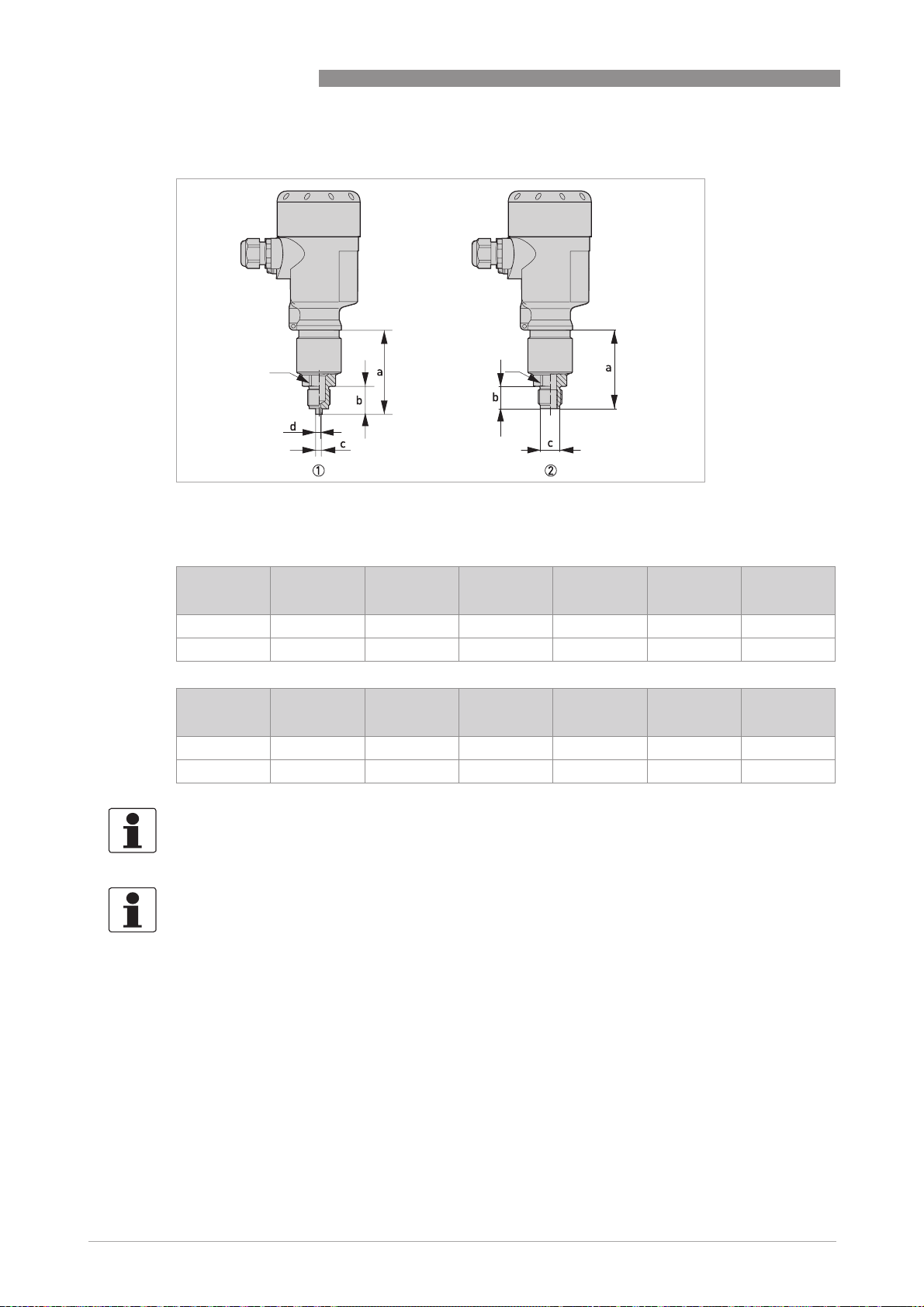
7 TECHNICAL DATA
OPTIBAR PC 5060 C
f
Figure 7-8: Thread not flush
1 Thread ISO228 G1/2 EN837-1
2 Thread ISO228 G1/2 - G1/4 female DIN3852
Dimension
a b c d e f
f
[mm]
1 73 23 6 3 - WS 27
2 70 20 17.5 - - G1/2
Dimension
a b c d e f
[inch]
1 2.87 0.91 0.24 0.12 - 1.06
2 2.76 0.79 0.69 - - G1/2
INFORMATION!
°
For the version with a temperature range up to 150
C / 302 °F the measure of length increases
by 28 mm / 1.1".
74
INFORMATION!
For the version with "secondary process barrier" the measure of length increases by
17 mm / 0.67".
www.krohne.com 04/2014 - 4003437201 - MA OPTIBAR PC 5060 C R01 en
Page 75

OPTIBAR PC 5060 C
Figure 7-9: Thread not flush
1 Thread ISO228 G1/2 EN837-1, volume reduced
2 Thread ANSI 1/2 NPT - 1/4 NPT female
3 Thread DIN13 M20 x 1.5 EN837-1
TECHNICAL DATA 7
Dimension
a b c d e f
[mm]
1 73 23 6 3 - -
2 75 15 - - - -
3 75 25 6 3 - -
Dimension
a b c d e f
[inch]
1 2.87 0.91 0.24 0.12 - -
2 2.95 0.59 - - - -
3 2.95 0.98 0.24 0.12 - -
INFORMATION!
°
For the version with a temperature range up to 150
C / 302 °F the measure of length increases
by 28 mm / 1.1".
INFORMATION!
For the version with "secondary process barrier" the measure of length increases by
17 mm / 0.67".
www.krohne.com04/2014 - 4003437201 - MA OPTIBAR PC 5060 C R01 en
75
Page 76

7 TECHNICAL DATA
OPTIBAR PC 5060 C
f
Figure 7-10: Thread flush
1 Thread ISO228 G1/2 DIN3852, flush
2 Thread ISO228 G3/4 DIN3852
3 Thread ISO228 G1 DIN3852
Dimension
a b c d e f
f
f
[mm]
1 45 21 27 18 - WS 27
2 44 22 24 - - WS 36
3 44 21 40 30 - WS 41
Dimension
a b c d e f
[inch]
1 1.77 0.83 1.06 0.71 - 1.06
2 1.73 0.87 0.95 - - 1.42
3 1.73 0.83 1.58 1.18 - 1.61
76
INFORMATION!
°
For the version with a temperature range up to 150
C / 302 °F the measure of length increases
by 28 mm / 1.1".
INFORMATION!
For the version with "secondary process barrier" the measure of length increases by
17 mm / 0.67".
www.krohne.com 04/2014 - 4003437201 - MA OPTIBAR PC 5060 C R01 en
Page 77

OPTIBAR PC 5060 C
TECHNICAL DATA 7
f
Figure 7-11: Thread flush
1 Thread ISO228 G1 1/2 DIN3852
2 Thread ISO G1 1/2 PVDF DIN 3852-A-B
3 Thread ANSI 1 1/2 NPT
Dimension
a b c d e f
f f
[mm]
1 50 22 55 - - WS 46
2 50 22 55 - - WS 46
3 50 22 55 - - WS 46
Dimension
a b c d e f
[inch]
1 1.97 0.87 2.17 - - 1.81
2 1.97 0.87 2.17 - - 1.81
3 1.97 0.87 2.17 - - 1.81
INFORMATION!
°
For the version with a temperature range up to 150
C / 302 °F the measure of length increases
by 28 mm / 1.1".
INFORMATION!
For the version with "secondary process barrier" the measure of length increases by
17 mm / 0.67".
www.krohne.com04/2014 - 4003437201 - MA OPTIBAR PC 5060 C R01 en
77
Page 78

7 TECHNICAL DATA
Figure 7-12: Hygienic
1 Clamp DN50 2" PN16, DIN32676 / ISO2852
2 Hygienic connection with grooved union nut F40 PN25
3 Flange DRD PN40
OPTIBAR PC 5060 C
f
Dimension
a b c d e f
[mm]
1 51 - 48 64 - -
2 60 - - 78 - WS 46
3 55 - 66 105 - -
Dimension
a b c d e f
[inch]
1 2.01 - 1.89 2.52 - -
2 2.36 - - 3.07 - 1.81
3 2.17 - 2.60 4.13 - -
INFORMATION!
°
For the version with a temperature range up to 150
C / 302 °F the measure of length increases
by 28 mm / 1.1".
INFORMATION!
For the version with "secondary process barrier" the measure of length increases by
17 mm / 0.67".
78
www.krohne.com 04/2014 - 4003437201 - MA OPTIBAR PC 5060 C R01 en
Page 79

OPTIBAR PC 5060 C
Figure 7-13: Hygienic
1 Varivent N50-40 PN25, 316 L
2 Compression fitting DIN11851, DN40 PN40, 316 L
3 Compression fitting DIN 11864-1 Form A, DN50 PN 40
TECHNICAL DATA 7
Dimension
a b c d e f
[mm]
1 51 - 84 - - -
2 51 - 92 - - -
3 50 - 92 - - -
Dimension
a b c d e f
[inch]
1 2.01 - 3.31 - - -
2 2.01 - 3.62 - - -
3 1.97 - 3.62 - - -
INFORMATION!
°
For the version with a temperature range up to 150
C / 302 °F the measure of length increases
by 28 mm / 1.1".
INFORMATION!
For the version with "secondary process barrier" the measure of length increases by
17 mm / 0.67".
www.krohne.com04/2014 - 4003437201 - MA OPTIBAR PC 5060 C R01 en
79
Page 80

7 TECHNICAL DATA
OPTIBAR PC 5060 C
f
Figure 7-14: Flange with extension
1 Thread DIN13 M30x1.5
2 Thread DIN13 M44x1.25, pressure screw
3 Thread ISO228 G1, suitable for PASVE
Dimension
a b c d e f
f
f
[mm]
1 48 29 27.4 25 - M30x1.5
2 52 21 - - - M44x1.25
3 104.8 30 29.3 24.7 - G1
Dimension
a b c d e f
[inch]
1 1.89 1.14 1.08 0.98 - M30x1.5
2 2.05 0.83 - - - M44x1.25
3 4.13 1.18 0.97 0.97 - G1
INFORMATION!
°
For the version with a temperature range up to 150
C / 302 °F the measure of length increases
by 28 mm / 1.1".
INFORMATION!
For the version with "secondary process barrier" the measure of length increases by
17 mm / 0.67".
80
www.krohne.com 04/2014 - 4003437201 - MA OPTIBAR PC 5060 C R01 en
Page 81

OPTIBAR PC 5060 C
Figure 7-15: Flange with extension
1 Flanged connection DN50 PN40 with selectable extension
2 Flanged connection DN80 PN40 with selectable extension
TECHNICAL DATA 7
Dimension
a b c d e f
[mm]
1 40 30...300 32...60 - - -
2 40 25...300 4.8...90 - - -
Dimension
a b c d e f
[inch]
1 1.58 1.18...11.81 1.26...2.36 - - -
2 1.58 0.98...11.81 1.89...3.54 - - -
INFORMATION!
°
For the version with a temperature range up to 150
C / 302 °F the measure of length increases
by 28 mm / 1.1".
INFORMATION!
For the version with "secondary process barrier" the measure of length increases by
17 mm / 0.67".
www.krohne.com04/2014 - 4003437201 - MA OPTIBAR PC 5060 C R01 en
81
Page 82

7 TECHNICAL DATA
OPTIBAR PC 5060 C
e
f
g
h
i
k
Figure 7-16: External housing
1 Connection plug
2 Connection plug
3 Housing base in plastic
4 Housing base in stainless steel
Dimension [mm] Dimension [inch]
a 41.6 1.64
b 108 4.25
c 41.6 1.64
d 80 3.15
e 82 3.23
f 59 2.32
g 110 x 90 4.33 x 3.54
h 66 2.60
i 51 2.01
k 110 x 90 4.33 x 3.54
82
www.krohne.com 04/2014 - 4003437201 - MA OPTIBAR PC 5060 C R01 en
Page 83

OPTIBAR PC 5060 C
Figure 7-17: Mounting plate
a 93 3.66
b 110 4.33
c 90 3.54
d 70 2.76
e 3 0.12
f 8 0.31
TECHNICAL DATA 7
ef
Dimension [mm] Dimension [inch]
www.krohne.com04/2014 - 4003437201 - MA OPTIBAR PC 5060 C R01 en
83
Page 84

7 TECHNICAL DATA
Figure 7-18: Dimensions - Flange
Flange connection acc. to DIN 2501 or ASME B16.5
OPTIBAR PC 5060 C
e
f
g
Dimension [mm] a b c d e f g
DN40 PN40 Form C 50 4 x Ø 18 18 3 88 110 150
DN50 PN40 Form C 50 4 x Ø 18 20 3 102 125 165
DN80 PN40 Form C 50 8 x Ø 18 24 3 138 180 200
2" Class 150lb RF 50 4 x Ø 19.1 19.1 3.2 91.9 120.7 152.4
3" Class 150lb RF 50 8 x Ø 19,1 23.9 3.2 127 152.4 190.5
Flange connection acc. to DIN 2501 or ASME B16.5
Dimension [inch] a b c d e f g
DN40 PN40 Form C 1.97 4 x Ø 0.71 0.71 0.12 3.46 4.33 5.91
DN50 PN40 Form C 1.97 4 x Ø 0.71 0.79 0.12 4.02 4.92 6.50
DN80 PN40 Form C 1.97 8 x Ø 0.71 0.95 0.12 5.43 6.30 7.87
2" Class 150lb RF 1.97 4 x Ø 0.75 0.75 0.13 3.62 4.75 6
3" Class 150lb RF 1.97 8 x Ø 0.75 0.94 0.13 5 6 7.50
INFORMATION!
°
For the version with a temperature range up to 150
C / 302 °F the measure of length increases
by 28 mm / 1.1".
INFORMATION!
For the version with "secondary process barrier" the measure of length increases by
17 mm / 0.67".
84
INFORMATION!
Other versions are available on request.
www.krohne.com 04/2014 - 4003437201 - MA OPTIBAR PC 5060 C R01 en
Page 85

OPTIBAR PC 5060 C
8.1 General description
The open HART® protocol, which can be used for free, is integrated into the signal converter for
communication.
Devices which support the HART
devices. When it comes to operating devices (Master), both manual control units (Secondary
Master) and PC-supported workstations (Primary Master) are used in, for example, a control
centre.
®
HART
devices range from 2-wire to intrinsically safe versions for use in hazardous areas.
The HART
all of the connected devices can communicate digitally with one another via the HART
while simultaneously transmitting the analogue signals.
When it comes to the field devices and secondary masters, the FSK or HART
integrated. If a PC is used, an external modem must be connected to the serial interface (USB
interface). There are, however, other connection variants which can be seen in the following
connection figures.
field devices include measuring sensors, signal converters and actuators. The field
®
data are superimposed over the analogue 4...20 mA signal via FSK modem. This way,
DESCRIPTION OF HART INTERFACE 8
®
protocol are classified as either operating devices or field
®
protocol
®
modem is
8.2 Software history
INFORMATION!
In the table below, "x" is a placeholder for possible multi-digit alphanumeric combinations,
depending on the available version.
Release date SW version HW version
2013-04-01 1.0.x 1.0.x 1 1
HART® identification codes and revision numbers
Manufacturer ID: 69 (0x45)
Device: 195 (0xC5)
Device Revision: 1
DD Revision: 1
HART® Universal Revision:
FC 475 system SW.Rev.: ≥ 3.7
PDM version: ≥ 8.0
FDT version: ≥ 1.2
®
HART
Device Revision DD Revision
7
www.krohne.com04/2014 - 4003437201 - MA OPTIBAR PC 5060 C R01 en
85
Page 86

8 DESCRIPTION OF HART INTERFACE
8.3 Connection variants
The signal converter is a 2-wire device with a passive 4...20 mA current output and a HART®
interface.
• Point-to-Point is supported
Point-to-Point is supported
Point-to-Point is supportedPoint-to-Point is supported
In conventional point-to-point operation, the signal converter communicates as a slave with
the master.
• Multidrop mode is supported
Multidrop mode is supported
Multidrop mode is supportedMultidrop mode is supported
In a multidrop communication system, more than 2 devices are connected to a common
transmission cable.
• Burst mode is not supported
Burst mode is not supported
Burst mode is not supportedBurst mode is not supported
In the burst operation a slave device transfers cyclic pre-defined response telegrams, to get a
higher rate of data transfer.
®
There are two ways of using the HART
• as Point-to-Point connection and
• as multidrop connection, with 2-wire connection.
communication:
OPTIBAR PC 5060 C
86
www.krohne.com 04/2014 - 4003437201 - MA OPTIBAR PC 5060 C R01 en
Page 87

OPTIBAR PC 5060 C
DESCRIPTION OF HART INTERFACE 8
8.3.1 Point-to-Point connection - analogue / digital mode
Point-to-Point connection between the signal converter and the HART® Master.
The current output of the device is passive.
Figure 8-1: Point-to-Point connection
®
DD
TM
FDT/DTM
1 Primary master with e.g. PACTware
2 FSK modem
3 HART
4 OPTIBAR DP 7060 C
5 Secondary master with HART
6 Power supply for devices (slaves) with passive current output
7 Load ≥ 250 Ω (Ohm)
®
signal
8.4 Inputs/outputs and HART® dynamic variables and device variables
PV = Primary Variable; SV = Secondary Variable; TV = Third Variable; QV = Quarternary Variable
HART® dynamic variable
PV SV TV QV
Linear percent value Physical unit Meas. cell temp. Electronic temperature
Table 8-1: HART® output values acc. to HART® 7 (factory setting)
www.krohne.com04/2014 - 4003437201 - MA OPTIBAR PC 5060 C R01 en
87
Page 88

8 DESCRIPTION OF HART INTERFACE
8.5 Field Communicator 475 (FC 475)
The Field Communicator is a hand terminal from Emerson Process Management that is
®
designed to configure HART
used to integrate different devices into the Field Communicator.
8.5.1 Installation
The HART® Device Description for the signal converter must be installed on the Field
Communicator. Otherwise only the functions of a generic DD are available to the user and the
entire device control is not possible. A "Field Communicator Easy Upgrade Programming Utility"
is required to install the DDs on the Field Communicator.
The Field Communicator must be equipped with a system card with "Easy Upgrade Option". For
details consult the Field Communicator User’s Manual.
8.5.2 Operation
Operating the signal converter via the Field Communicator is very similar to manual device
control using the keyboard.
and Foundation Fieldbus devices. Device Descriptions (DDs) are
OPTIBAR PC 5060 C
8.6 Field Device Tool / Device Type Manager (FDT / DTM)
A Field Device Tool Container (FDT Container) is basically a PC program used to configure a field
®
device via HART
Manager (DTM).
8.6.1 Installation
If the DTM for the signal converter has not yet been installed on the FDT Container, setup is
required and is available for download from the website or on CD-ROM. See the supplied
documentation for information on how to install and set up the DTM.
. To adapt to different devices, the FDT container uses a so-called Device Type
88
www.krohne.com 04/2014 - 4003437201 - MA OPTIBAR PC 5060 C R01 en
Page 89

OPTIBAR PC 5060 C
NOTES 9
www.krohne.com04/2014 - 4003437201 - MA OPTIBAR PC 5060 C R01 en
89
Page 90

9 NOTES
OPTIBAR PC 5060 C
90
www.krohne.com 04/2014 - 4003437201 - MA OPTIBAR PC 5060 C R01 en
Page 91

OPTIBAR PC 5060 C
NOTES 9
www.krohne.com04/2014 - 4003437201 - MA OPTIBAR PC 5060 C R01 en
91
Page 92

KROHNE product overview
• Electromagnetic flowmeters
• Variable area flowmeters
• Ultrasonic flowmeters
• Mass flowmeters
• Vortex flowmeters
• Flow controllers
• Level meters
• Temperature assemblies
• Pressure transmitters
• Analysis products
• Products and systems for the oil & gas industry
• Measuring systems for the marine industry
Head Office KROHNE Messtechnik GmbH
Ludwig-Krohne-Str. 5
47058 Duisburg (Germany)
Tel.:+49 203 301 0
Fax:+49 203 301 103 89
info@krohne.com
The current list of all KROHNE contacts and addresses can be found at:
© KROHNE 04/2014 - 4003437201 - MA OPTIBAR PC 5060 C R01 en - Subject to change without notice.
www.krohne.com
 Loading...