

KROHNE OPTIWAVE 6300 C Specifications

Technical Datasheet
Technical Datasheet
OPTIWAVE 6300 C
OPTIWAVE 6300 C
OPTIWAVE 6300 COPTIWAVE 6300 C
Technical DatasheetTechnical Datasheet
24 GHz Non-contact Radar (FMCW) Level Meter
•
One converter for all antenna types (PTFE Drop, PP Drop and metallic horn)
•
The only guarantee for measuring accurately in dusty conditions
•
Uses a unique Drop antenna design for very dusty atmospheres
© KROHNE 01/2015 - 4000305606 - TD OPTIWAVE 6300 R06 en

CONTENTS
OPTIWAVE 6300 C
1 Product features 3
1.1 The radar solution for solids ............................................................................................ 3
1.2 Options.............................................................................................................................. 5
1.3 Measuring principle.......................................................................................................... 6
2 Technical data 7
2.1 Technical data................................................................................................................... 7
2.2 Antenna selection........................................................................................................... 12
2.3 Guidelines for maximum operating pressure................................................................ 13
2.4 Dimensions and weights ................................................................................................ 15
3 Installation 24
3.1 Intended use ................................................................................................................... 24
3.2 Pre-installation requirements ....................................................................................... 24
3.3 How to prepare the silo before you install the device ................................................... 24
3.3.1 Recommended mounting position........................................................................................ 24
3.4 Installation recommendations for solids....................................................................... 26
3.5 How to install the device on the silo .............................................................................. 27
3.5.1 How to install a device with a flange connection ................................................................. 27
3.5.2 How to install a device with a threaded connection............................................................. 27
4 Electrical connections 28
4.1 Safety instructions.......................................................................................................... 28
4.2 Electrical installation: outputs 1 and 2 .......................................................................... 28
4.2.1 Non-Ex devices ..................................................................................................................... 29
4.2.2 Devices for hazardous locations........................................................................................... 29
4.3 Protection category ........................................................................................................29
4.4 Networks ........................................................................................................................ 30
4.4.1 General information.............................................................................................................. 30
4.4.2 Point-to-point connection..................................................................................................... 30
4.4.3 Multi-drop networks ............................................................................................................. 31
5 Order information 32
5.1 Order code ...................................................................................................................... 32
2
www.krohne.com 01/2015 - 4000305606 - TD OPTIWAVE 6300 R06 en

OPTIWAVE 6300 C
1.1 The radar solution for solids
This device is a non-contact Radar (FMCW) Level Meter for distance, level, volume, mass and
reflectivity measurement of powders, granulates and other solids. It gives a stabler
measurement than pulse radar and is well suited to dusty process conditions. The device can
operate at very low and very high process temperatures as long as the process connection
temperature limits are observed.
PRODUCT FEATURES
1
1 Optional touch screen with 4-button operation
2 2-wire level meter
3 Removable and rotatable converter with quick connector system
4 Stainless steel horn or PTFE/PP Drop antennas
5 Optional flange plate protection (for corrosive products) or antenna extension (for long nozzles)
6 One converter for all applications
www.krohne.com01/2015 - 4000305606 - TD OPTIWAVE 6300 R06 en
3

1
PRODUCT FEATURES
Highlights
• ±3mm/ ±0.12¨ standard accuracy
• PP or PTFE Drop antenna: its shape prevents product build-up in dusty applications
• Operates up to a flange temperature of +200°C / +390°F and 40 bar / 580 psig
• Measuring range up to 80 m / 260 ft
• Antenna can be extended to suit any nozzle length
• PACTware and DTMs included as standard
• Optional second current output
• Directly-accessible graphic touchscreen/wizard (option)
• An installation wizard specifically for solids that permits the instrument to measure uneven
surfaces accurately
Industries
• Minerals & Mining
• Chemical
• Food
• Iron, Steel & Metals
• Pulp & Paper
OPTIWAVE 6300 C
Applications
• Storage
• Silos
• Hoppers
4
www.krohne.com 01/2015 - 4000305606 - TD OPTIWAVE 6300 R06 en

OPTIWAVE 6300 C
1.2 Options
Drop antennas
PRODUCT FEATURES
Drop antennas are a unique innovation to measure
powders and other solids in very dusty atmospheres.
The ellipsoidal shape of the antennas prevents
build-up and generates a small beam angle for
accurate measurement of silo contents. They have
these features:
• 2 antenna sizes: DN80 or DN150.
• An installation wizard specifically for solids that
permits the instrument to measure uneven
surfaces accurately.
• Antennas can be extended to suit any nozzle length.
• Made of either PP or PTFE.
1
Horn antennas
Use of metal horn antennas is recommended for
measuring granulates, high-pressure and hightemperature applications, cement works or
processes with cyclone separators. They are
particularly resistant to mechanical shocks. They
have these features:
• Made of stainless steel 316L.
• 4 antenna sizes: DN80, DN100, DN150 or DN200.
• Antennas can be extended to suit any nozzle length.
www.krohne.com01/2015 - 4000305606 - TD OPTIWAVE 6300 R06 en
5
1
PRODUCT FEATURES
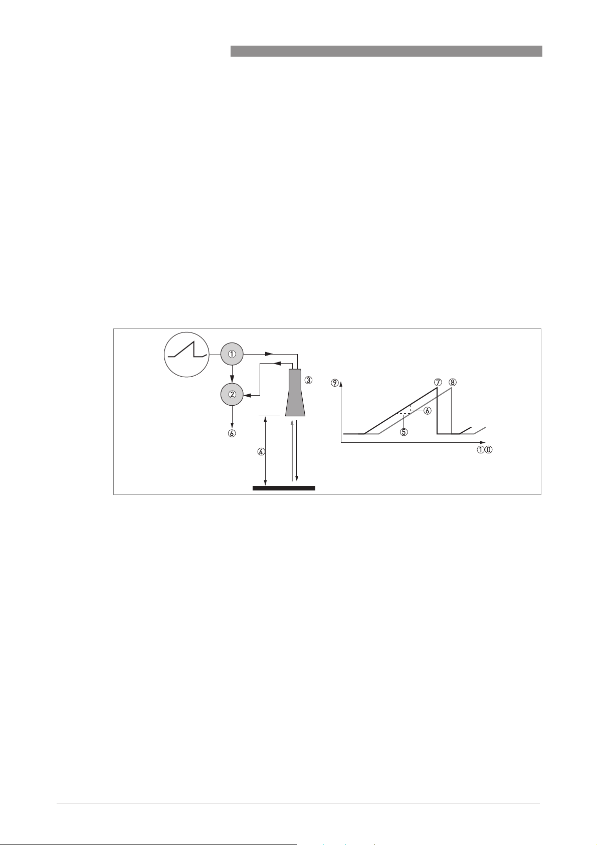
1.3 Measuring principle
A radar signal is emitted via an antenna, reflected from the product surface and received after a
time t. The radar principle used is FMCW (Frequency Modulated Continuous Wave).
The FMCW-radar transmits a high frequency signal whose frequency increases linearly during
the measurement phase (called the frequency sweep). The signal is emitted, reflected on the
measuring surface and received with a time delay, t. Delay time, t=2d/c, where d is the distance
to the product surface and c is the speed of light in the gas above the product.
For further signal processing the difference Δf is calculated from the actual transmitted
frequency and the received frequency. The difference is directly proportional to the distance. A
large frequency difference corresponds to a large distance and vice versa. The frequency
difference Δf is transformed via a Fourier transformation (FFT) into a frequency spectrum and
then the distance is calculated from the spectrum. The level results from the difference between
tank height and measuring distance.
OPTIWAVE 6300 C
Figure 1-1: Measuring principle of FMCW radar
1 Transmitter
2 Mixer
3 Antenna
4 Distance to product surface, where change in frequency is proportional to distance
5 Differential time delay, Δt
6 Differential frequency, Δf
7 Frequency transmitted
8 Frequency received
9 Frequency
10 Time
6
www.krohne.com 01/2015 - 4000305606 - TD OPTIWAVE 6300 R06 en

OPTIWAVE 6300 C
TECHNICAL DATA
2.1 Technical data
•
The following data is provided for general applications. If you require data that is more
relevant to your specific application, please contact us or your local sales office.
•
Additional information (certificates, special tools, software,...) and complete product
documentation can be downloaded free of charge from the website (Download Center).
Measuring system
Measuring principle 2-wire loop-powered level transmitter; K-band (24...26 GHz) FMCW radar
Application range Level measurement of powders and granulates
Primary measured value Δf (change in frequency) between the emitted and received signal
Secondary measured value Distance, level, volume, mass and reflectivity
Design
Construction The measurement system consists of a measuring sensor (antenna) and a signal
Standard Antenna purging system for horn antenna (supplied with a ¼ NPTF connection
Options Integrated LCD display with sun cover (-20..+60°C/ -4…+140°F); if the ambient
Accessories Weather protection
Max. measuring range 80 m / 260 ft
Min. tank height 0.2 m / 8¨
Min. dead zone Antenna extension length + antenna length + 0.3 m / 12¨
Beam angle of antenna Horn / Sheet metal horn DN80 / 3¨: 10°
Display and user interface
Display and user interface
Display and user interfaceDisplay and user interface
Display LCD display
Interface languages English, German, French, Italian, Spanish, Portuguese, Japanese, Simplified
converter which is only available in a compact version
– for horn antenna only)
temperature is not in these limits, the display switches off
2nd current output
PTFE/PP flange plate protection (for Drop antenna without antenna extensions only)
Distance piece (for process temperature: +150...+200°C / +300...+390°F)
Antenna extensions of 105 mm / 4.1¨ length (max. length for Drop antenna versions:
525 mm / 20.7¨)
2° slanted PP flange (for all antennas)
Discs (low-pressure flanges) with bolt hole dimensions and positions that agree
with DN80...200 in PN06 or 3¨...8¨ in 150 lb for devices with the G 1½ threaded
connection. Max. pressure: 1 barg / 14.5 psig at +20°C / +68°F.
Depends on the antenna option, dielectric constant of the product and installation
type. Refer also to "Antenna selection".
Horn / Sheet metal horn DN100 / 4¨: 8°
Sheet metal horn DN150 / 6¨: 6°
Sheet metal horn DN200 / 8¨: 4°
Drop DN80 / 3¨: 8°
Drop DN150 / 6¨: 4°
9 lines, 160 × 160 pixels in 8-step grayscale with 4-button keypad
Chinese and Russian
2
www.krohne.com01/2015 - 4000305606 - TD OPTIWAVE 6300 R06 en
7

2
TECHNICAL DATA
OPTIWAVE 6300 C
Measurement accuracy
Resolution 1mm/ 0.04¨
Repeatability ±1mm/ ±0.04¨
Accuracy ±3mm/ ±0.12¨, when distance <10m/ 33ft;
Reference conditions acc. to EN 60770
Reference conditions acc. to EN 60770
Reference conditions acc. to EN 60770Reference conditions acc. to EN 60770
Temperature +20°C ±5°C / +70°F ±10°F
Pressure 1013 mbara ±20 mbar / 14.69 psia ±0.29 psi
Relative air humidity 60% ±15%
Target Metal plate in an anechoic chamber
±0.03% of measured distance, when distance > 10 m / 33 ft
Operating conditions
Temperature
Temperature
TemperatureTemperature
Ambient temperature -40…+80°C/ -40…+175°F (according to the temperature limits of the gasket
Storage temperature -40…+85°C/ -40…+185°F
Flange temperature Horn / Sheet metal horn antenna:
Pressure
Pressure
PressurePressure
Operating pressure Drop antenna (PP):
Other conditions
Other conditions
Other conditionsOther conditions
Dielectric constant (εr) ≥1.5
Vibration resistance IEC 60068-2-6 and EN 50178 (10...57 Hz: 0.075 mm / 57...150 Hz:1g)
Protection category IP 66/67 equivalent to NEMA type 4X (housing) and type 6P (antenna)
Maximum rate of change 10 m/min / 33 ft/min
material. Refer to "Materials" in this table.)
Ex: see supplementary operating instructions or approval certificates
Horn / Sheet metal horn antenna:
Horn / Sheet metal horn antenna:Horn / Sheet metal horn antenna:
Standard: -50…+150°C/ -58…+300°F
Option: -50…+200°C/ -58…+390°F
(the process connection temperature must agree with the temperature limits of the
gasket material. Refer to "Materials" in this table.)
Ex: see supplementary operating instructions or approval certificates
Drop antenna (PTFE):
Drop antenna (PTFE):
Drop antenna (PTFE):Drop antenna (PTFE):
-50…+150°C/ -58…+300°F (the process connection temperature must agree with
the temperature limits of the gasket material. Refer to "Materials" in this table.)
Ex: see supplementary operating instructions or approval certificates
Drop antenna (PP):
Drop antenna (PP):
Drop antenna (PP):Drop antenna (PP):
-40…+100°C/ -40…+210°F (the process connection temperature must agree with
the temperature limits of the gasket material. Refer to "Materials" in this table.)
Ex: see supplementary operating instructions or approval certificates
Drop antenna (PP):
Drop antenna (PP):Drop antenna (PP):
-1…16 barg / -14.5…232 psig;
subject to process connection used and flange temperature
Drop antenna (PTFE):
Drop antenna (PTFE):
Drop antenna (PTFE):Drop antenna (PTFE):
-1…40 barg / -14.5…580 psig;
subject to process connection used and flange temperature
Horn / Sheet metal horn antenna:
Horn / Sheet metal horn antenna:
Horn / Sheet metal horn antenna:Horn / Sheet metal horn antenna:
Standard: -1…40 barg / -14.5…580 psig;
subject to process connection used and flange temperature
8
www.krohne.com 01/2015 - 4000305606 - TD OPTIWAVE 6300 R06 en

OPTIWAVE 6300 C
TECHNICAL DATA
Installation conditions
Process connection size The nominal diameter (DN) should be equal to or larger than the antenna diameter.
If the nominal diameter (DN) is smaller than the antenna, either:
– provide the means to adapt the device to a larger process connection on the silo
(for example, a plate with a slot), or
– use the same process connection, but remove the antenna from the device before
installation and fit it from inside the silo
Process connection position Make sure that there are not any obstructions directly below the process
Dimensions and weights Refer to "Technical data: Dimensions and weights".
connection for the device.
Materials
Housing Standard: Polyester-coated aluminium
Option: Stainless steel (1.4404 / 316L)
Wetted parts, including antenna Horn / Sheet metal horn antenna: Stainless steel (1.4404 / 316L)
Drop antenna: PTFE; PP – a PP or PTFE flange plate protection option is also
available
Process connection Stainless steel (1.4404 / 316L) – a PP or PTFE flange plate protection option is also
Gaskets (and o-rings for the
sealed antenna extension option)
Feedthrough Standard: PEI (-50...+200°C / -58...+390°F – max. range. The feedthrough
Weather protection (Option) Stainless steel (1.4301 / 304)
available for the Drop antenna
PTFE Drop antenna:
PTFE Drop antenna:
PTFE Drop antenna:PTFE Drop antenna:
FKM/FPM (-40…+150°C/ -40…+300°F); Kalrez® 6375 (-20…+150°C/ -4…+300°F);
EPDM (-50°C…+150°C/ -58…+300°F)
PP Drop antenna:
PP Drop antenna:
PP Drop antenna:PP Drop antenna:
FKM/FPM (-40…+100°C/ -40…+210°F); Kalrez® 6375 (-20…+100°C/ -4…+210°F);
EPDM (-40°C…+100°C/ -40…+210°F)
Horn / Sheet metal horn antenna:
Horn / Sheet metal horn antenna:
Horn / Sheet metal horn antenna:Horn / Sheet metal horn antenna:
FKM/FPM (-40…+200°C/ -40…+390°F); Kalrez® 6375 (-20…+200°C/ -4…+390°F);
EPDM (-50°C…+150°C/ -58…+300°F)
temperature limits must agree with the temperature limits of the gasket material
and antenna type. If the distance piece option is not attached, the maximum
temperature is 150°C/ 300°F.)
Option: Metaglas® (-30...+200°C / -22...+390°F – max. range. The feedthrough
temperature limits must agree with the temperature limits of the gasket material
and antenna type. If the distance piece option is not attached, the maximum
temperature is 150°C/ 300°F.)
1
2
2
2
3
2
Process connections
Thread G1½ (ISO 228); 1½ NPT (ASME B1.20.1)
Flange version
Flange version
Flange versionFlange version
EN 1092-1 DN80 in PN40 (Type B1), DN100…200 in PN16 or PN40 (Type B1); others on request
ASME B16.5 3¨…8¨ in 150 lb RF, 3¨...4¨ in 300 lb RF; others on request
JIS B2220 80…100A in 10K; others on request
Other Others on request
www.krohne.com01/2015 - 4000305606 - TD OPTIWAVE 6300 R06 en
9

2
TECHNICAL DATA
Electrical connections
Power supply Terminals output 1
Cable entry M20×1.5; ½ NPT
Cable gland Standard: none
Cable entry capacity (terminal) 0.5…1.5 mm²
Terminals output 1 – Non-Ex / Ex i:
Terminals output 1 Terminals output 1
14…30 VDC; min./max. value for an output of 22 mA at the terminal
Terminals output 1
Terminals output 1 – Ex d:
Terminals output 1 Terminals output 1
20…36 VDC; min./max. value for an output of 22 mA at the terminal
Terminals output 2
Terminals output 2 – Non-Ex / Ex i / Ex d:
Terminals output 2 Terminals output 2
10…30 VDC; min./max. value for an output of 22 mA at the terminal (additional
power supply needed – output only)
G ½ (not for FM- and CSA-approved devices. Not for stainless steel housings.)
Stainless steel housings: M20×1.5
Options: M20×1.5; others are available on request
Non-Ex / Ex i:
Non-Ex / Ex i: Non-Ex / Ex i:
Ex d:
Ex d: Ex d:
Non-Ex / Ex i / Ex d:
Non-Ex / Ex i / Ex d: Non-Ex / Ex i / Ex d:
Input and output
Current output
Current output
Current outputCurrent output
Output signal
(Output 1)
Output signal
(Output 2 – optional)
Resolution ±3 µA
Temperature drift Typically 25 ppm/K
Error signal High: 22 mA; Low: 3.6 mA acc. to NAMUR NE 43
4…20 mA HART® or 3.8…20.5 mA acc. to NAMUR NE 43
4…20 mA (no HART® signal) or 3.8…20.5 mA acc. to NAMUR NE 43
OPTIWAVE 6300 C
4
Approvals and certification
CE This device fulfils the statutory requirements of the EC directives. The
Explosion protection
Explosion protection
Explosion protectionExplosion protection
ATEX
KEMA 04ATEX1218 X
IECEx
IECEx KEM 06.0025 X
FM – Dual Seal-approved NEC 500
manufacturer certifies successful testing of the product by applying the CE mark.
II 1G, 1/2G, 2G Ex ia IIC T6...T3;
II 1 D, 1/2 D, 2 D Ex iaD 20 or Ex iaD 20/21 or Ex iaD 21 IP6X T70°C...T95°C;
II 1/2 G, 2 G Ex d[ia] IIC T6...T3;
II 1/2 D, 2 D Ex tD[iaD] A21/20 or Ex tD[iaD] A21 IP6X T70°C...T95°C
Ga Ex ia IIC T6…T3; Ex iaD 20 IP6X T70°C…T95°C;
Ga/Gb Ex d[ia] IIC T6…T3; Ex tD[iaD] A21/20 IP6X T70°C…T95°C
NEC 500
NEC 500NEC 500
XP-IS / Cl. I / Div. 1 / Gr. ABCD / T6-T1;
DIP / Cl. II, III / Div. 1 / Gr. EFG / T6-T1;
IS / Cl. I, II, III / Div. 1 / Gr. ABCDEFG / T6-T1;
NI / Cl. I / Div. 2 / Gr. ABCD / T6-T1
NEC 505
NEC 505
NEC 505NEC 505
Cl. I / Zone 0 / AEx d[ia] / IIC / T6-T1;
Cl. I / Zone 0 / AEx ia / IIC / T6-T1;
Cl. I / Zone 2 / AEx nA[ia] / IIC / T6-T1
Hazardous (Classified) Locations, indoor/outdoor Type 4X and 6P, IP66, Dual Seal
10
www.krohne.com 01/2015 - 4000305606 - TD OPTIWAVE 6300 R06 en

OPTIWAVE 6300 C
TECHNICAL DATA
2
CSA – Dual Seal-approved CEC Section 18 (Zone ratings)
NEPSI
GYJ091178/79
DNV / INMETRO
DNV 12.0043 X
KGS
11-GA4BO-0325X
11-GA4BO-0326X
Other standards and approvals
Other standards and approvals
Other standards and approvalsOther standards and approvals
EMC Electromagnetic Compatibility Directive 2004/108/EC in conjunction with
R & TTE Radio Equipment and Telecommunications Terminal Equipment Directive
FCC Rules Part 15
Industry Canada RSS-210
LVD Low-Voltage Directive 2006/95/EC in conjunction with EN 61010-1 (2001)
CRN This certification is for all Canadian provinces and territories. For more data, refer
NAMUR NAMUR NE 21 Electromagnetic Compatibility (EMC) of Industrial Process and
1 This option is not available for FM- or CSA-approved devices
2 Kalrez® is a registered trademark of DuPont Performance Elastomers L.L.C.
3 Metaglas® is a registered trademark of Herberts Industrieglas, GMBH & Co., KG
4 HART® is a registered trademark of the HART Communication Foundation
CEC Section 18 (Zone ratings)
CEC Section 18 (Zone ratings)CEC Section 18 (Zone ratings)
Cl. I, Zone 1, Ex d, IIC (Antenna: Zone 0) T6;
Cl. I, Zone 0, Ex ia, IIC T6;
Cl. I, Zone 2, Ex nA, IIC T6
CEC Section 18 and Annex J (Division ratings)
CEC Section 18 and Annex J (Division ratings)
CEC Section 18 and Annex J (Division ratings)CEC Section 18 and Annex J (Division ratings)
XP-IS, Cl. I, Div. 2, Gr. ABCD; Cl. II, Div. 2, Gr. FG; Cl. III, Div. 2 T6;
IS, Cl. I, Div. 1, Gr. ABCD; Cl. II, Gr. FG; Cl. III T6
Ex d ia IIC T3~T6 DIP A21/20 T
Ex ia IIC T3~T6 DIP A21/20 T
Ex ia IIC T6…T3 Ga; Ex ia IIIC T70°C...T95°C Da IP6X;
Ex d [ia Ga] IIC T6...T3 Ga/Gb; Ex tb [ia Da] IIIC T70°C...T95°C Db IP6X
Ex ia IIC T6~T3; Ex iaD 20 IP6X T70°C~T95°C;
Ex d[ia] IIC T6~T3; Ex tD[iaD] A21/20 IP6X T70°C~T95°C
EN 61326-1 (2013)
1999/5/EC in conjunction with ETSI EN 302 372-2 (2011) and ETSI EN 302 729-2
(2011)
to the website.
Laboratory Control Equipment
NAMUR NE 43 Standardization of the Signal Level for the Failure Information of
Digital Transmitters
T70°C~T95°C IP6X;
A
T70°C~T95°C IP6X
A
www.krohne.com01/2015 - 4000305606 - TD OPTIWAVE 6300 R06 en
11
 Loading...