

Page 1
Technical Datasheet
Technical Datasheet
OPTIWAVE 1400 C
OPTIWAVE 1400 C
OPTIWAVE 1400 COPTIWAVE 1400 C
Technical DatasheetTechnical Datasheet
24 GHz Radar (FMCW) Level Transmitter for liquids in
the water and waste water industry
•
Proven Polypropylene (PP) Drop antenna, insensitive to condensation or deposits
•
Narrow beam angle for a sharp focus on the medium
•
Robust stainless steel design (IP68 / NEMA 4X/6)
© KROHNE 05/2019 - 4007613001 - TD OPTIWAVE 1400 R01 en
Page 2

CONTENTS
OPTIWAVE 1400 C
1 Product features 3
1.1 The FMCW radar level transmitter for liquids in the water and wastewater industry ... 3
1.2 Measuring principle.......................................................................................................... 4
2 Technical data 5
2.1 Technical data................................................................................................................... 5
2.2 Measuring accuracy .........................................................................................................8
2.3 Minimum power supply voltage ....................................................................................... 9
2.4 Dimensions and weights ................................................................................................ 10
3 Installation 19
3.1 Intended use ................................................................................................................... 19
3.2 Pre-installation requirements ....................................................................................... 19
3.3 Installation...................................................................................................................... 20
3.3.1 Pressure and temperature ranges....................................................................................... 20
3.3.2 Recommended mounting position: tanks............................................................................. 21
3.3.3 Recommended mounting position........................................................................................ 22
3.3.4 Mounting restrictions............................................................................................................ 23
3.3.5 Recommended mounting position: flow channels ............................................................... 24
3.3.6 Recommendations for pits and tanks made of non-conductive materials.......................... 25
4 Electrical connections 26
4.1 Non-Ex devices............................................................................................................... 26
4.2 Networks ........................................................................................................................ 27
4.2.1 General information.............................................................................................................. 27
4.2.2 Point-to-point connection..................................................................................................... 27
4.2.3 Multi-drop networks ............................................................................................................. 28
5 Order information 29
5.1 Accessories..................................................................................................................... 29
6 Notes 30
2
www.krohne.com 05/2019 - 4007613001 - TD OPTIWAVE 1400 R01 en
Page 3

OPTIWAVE 1400 C
PRODUCT FEATURES
1.1 The FMCW radar level transmitter for liquids in the water and
wastewater industry
This device is a non-contact radar level transmitter that uses FMCW technology. It measures
distance, level and volume of liquids and pastes. It is a device that provides accurate readings in
closed tanks, in the open air like rivers or dams, and can even measure volumetric flow rate.
1
1 PP Drop antenna. The PP Drop antenna has a small beam angle and is insensitive to condensation or deposits.
2 2-wire 24 GHz FMCW radar level transmitter
3 10-metre electrical cable
4 Watertight stainless steel housing
Highlights
• KROHNE is the pioneer of FMCW radar and has over 30 years of experience with this
technology
• Accuracy: ±2mm/ ±0.08¨
• Measuring range: 20 m / 66 ft
• Small beam angle
• Process temperature: -20...+80°C / -4...+176°F
• Process pressure: -1...3 barg / -14.5...43.5 psig
• 2-wire 4...20 mA (HART® 7)
• Maintenance-free concept
• Installation and operation made simple, safe and secure
• 3-year warranty
Industries
• Water
• Wastewater
www.krohne.com05/2019 - 4007613001 - TD OPTIWAVE 1400 R01 en
3
Page 4
1
PRODUCT FEATURES
Applications
• Extraction, transport, storage and distribution of water from springs, rivers, lakes or the sea
• Rainwater basins
• Open-channel flow measurement
• Water, wastewater, sludge or other liquids in storage applications
• Wastewater pumping stations
• Floodwater alarm
• Liquid level of plastic tanks e.g. Intermediate Bulk Containers (IBC)
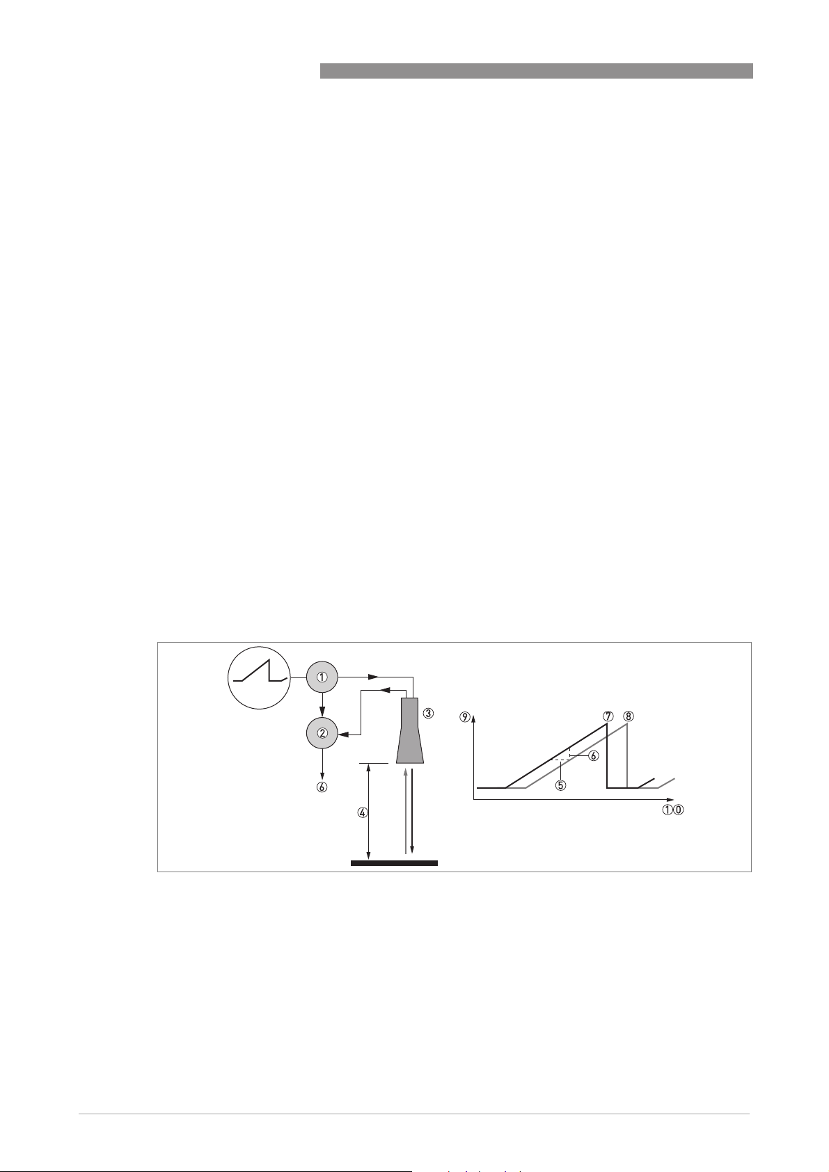
1.2 Measuring principle
A radar signal is emitted via an antenna, reflected from the product surface and received after a
time t. The radar principle used is FMCW (Frequency Modulated Continuous Wave).
The FMCW-radar transmits a high frequency signal whose frequency increases linearly during
the measurement phase (called the frequency sweep). The signal is emitted, reflected on the
measuring surface and received with a time delay, t. Delay time, t=2d/c, where d is the distance
to the product surface and c is the speed of light in the gas above the product.
OPTIWAVE 1400 C
For further signal processing the difference Δf is calculated from the actual transmitted
frequency and the received frequency. The difference is directly proportional to the distance. A
large frequency difference corresponds to a large distance and vice versa. The frequency
difference Δf is transformed via a Fast Fourier Transform (FFT) into a frequency spectrum and
then the distance is calculated from the spectrum. The level results from the difference between
the tank height and the measured distance.
Figure 1-1: Measuring principle of FMCW radar
1 Transmitter
2 Mixer
3 Antenna
4 Distance to product surface, where change in frequency is proportional to distance
5 Differential time delay, Δt
6 Differential frequency, Δf
7 Frequency transmitted
8 Frequency received
9 Frequency
10 Time
4
www.krohne.com 05/2019 - 4007613001 - TD OPTIWAVE 1400 R01 en
Page 5

OPTIWAVE 1400 C
TECHNICAL DATA
2.1 Technical data
•
The following data is provided for general applications. If you require data that is more
relevant to your specific application, please contact us or your local sales office.
•
Additional information (certificates, special tools, software,...) and complete product
documentation can be downloaded free of charge from the website (Downloadcenter).
Measuring system
Measuring principle 2-wire loop-powered level transmitter; FMCW radar
Frequency range K-band (24...26 GHz)
Max. radiated power (EIRP) <-41.3dBm according to ETSIEN302729 (LPR)
Application range Level measurement of liquids, pastes and slurries
Primary measured value Distance and reflection
Secondary measured value Level, volume, mass and flow rate
Design
Construction The measurement system consists of a measuring sensor (antenna) and a signal
Max. measuring range
(antenna)
Min. tank height 0.2 m / 8¨
Recommended minimum
blocking distance
Beam angle (antenna) PP Drop, DN100 / 4¨: 8°
User interface
User interface
User interfaceUser interface
User interface options HART® Field Communicator. Download the Device Description (DD) file from the
converter
20 m / 65.6 ft
0.8 m / 31.5¨
website.
System or PC with PACTware™. Download the Device Type Manager (DTM) file from
the website.
2
Measuring accuracy
Resolution 1mm/ 0.04¨
Repeatability ±1mm/ ±0.04¨
Accuracy Standard: ±2mm/ ±0.8¨, when distance ≤ 10 m / 33 ft;
Reference conditions acc. to EN 61298-1
Reference conditions acc. to EN 61298-1
Reference conditions acc. to EN 61298-1Reference conditions acc. to EN 61298-1
Temperature +15...+25°C / +59...+77°F
Pressure 1013 mbara ±50 mbar / 14.69 psia ±0.73 psi
Relative air humidity (RH) 60% ±15%
Target Metal plate in an anechoic chamber
±0.02% of measured distance, when distance > 10 m / 33 ft. For more data, refer to
Measuring accuracy
on page 8.
Operating conditions
Temperature
Temperature
TemperatureTemperature
Ambient temperature -20…+80°C/ -4…+176°F
Relative humidity (RH) 0...99%
Storage temperature -40…+85°C/ -40…+185°F
www.krohne.com05/2019 - 4007613001 - TD OPTIWAVE 1400 R01 en
5
Page 6

2
TECHNICAL DATA
OPTIWAVE 1400 C
Process connection temperature
(higher temperature on request)
Pressure
Pressure
PressurePressure
Process pressure Subject to the process connection used and the process connection temperature.
Other conditions
Other conditions
Other conditionsOther conditions
Dielectric constant (εr) Direct mode: ≥2
Ingress protection IEC 60529: IP66 / IP68 (continuous immersion at a gauge pressure of 0.2 barg for 2
Maximum rate of change 60 m/min / 196 ft/min
-40…+80°C/ -40…+176°F
For more data, refer to
weeks)
NEMA 250: NEMA type 4X/6
Pressure and temperature ranges
on page 20.
Installation conditions
Process connection size The nominal diameter (DN) should be equal to or larger than the antenna diameter.
Process connection position Make sure that there are not any obstructions directly below the process
Dimensions and weights For dimensions and weights data, refer to
connection for the device. For more data, refer to
Dimensions and weights
Installation
on page 19.
on page 10.
Materials
Housing Standard: Stainless steel (1.4404 / 316L)
Wetted parts, including antenna PP and stainless steel (1.4404 / 316L)
Process connection Standard: Stainless steel (1.4404 / 316L)
Option: PP
Cable gland M20×1.5 with aluminium clamp
Process connections
Bottom of housing G 3 A (ISO 228)
Top of housing G 1 A (ISO 228)
Flange version
Flange version
Flange versionFlange version
EN 1092-1 DN80...100 in PN01 (max. 3 bar)
ASME B16.5 3...4¨ in Class 150 (max. 15 psig)
Other Others on request
Electrical connections
Power supply 12…30 V DC; min./max. value for an output of 21.5 mA at the terminals
Maximum current 21.5 mA
Current output load RL [Ω] ≤ ((U
voltage
Cable entry M20×1.5
Cable entry capacity (terminal) 0.5…3.31 mm² (AWG 20...12)
-12 V)/21.5 mA). For more data, refer to
ext
on page 9.
Minimum power supply
Input and output
Current output
Current output
Current outputCurrent output
Output signal Standard: 4…20 mA
Options: 3.8…20.5 mA acc. to NAMUR NE 43; 4…20 mA (reversed); 3.8…20.5 mA
(reversed) acc. to NAMUR NE 43
Output type Passive
6
www.krohne.com 05/2019 - 4007613001 - TD OPTIWAVE 1400 R01 en
Page 7

OPTIWAVE 1400 C
Resolution ±5 µA
Temperature drift Typically 50 ppm/K
Error signal High: 21.5 mA; Low: 3.5 mA acc. to NAMUR NE 43
HART
HART®
HARTHART
Description Digital signal transmitted with the current output signal (HART® protocol)
Version 7.4
Load ≥ 250 Ω
Digital temperature drift Max. ±15 mm / 0.6¨ for the full temperature range
Multi-drop operation Yes. Current output = 4 mA. Enter Program mode to change the polling address
Available drivers FC475, AMS, PDM, FDT/DTM
(1...63).
TECHNICAL DATA
1
Approvals and certification
CE The device meets the essential requirements of the EU Directives. The
Vibration resistance EN 60068-2-6 (5...8.51 Hz: 3 mm / 8.51...200 Hz:1g)
Shock resistance EN 60068-2-27 (25g shock ½ sinus: 6 ms)
Other standards and approvals
Other standards and approvals
Other standards and approvalsOther standards and approvals
Electromagnetic compatibility EU
Radio approvals EU
Electrical safety EU
NAMUR NAMUR NE 43 Standardization of the Signal Level for the Failure Information of
1 HART® is a registered trademark of the HART Communication Foundation
manufacturer certifies successful testing of the product by applying the CE
marking.
For more data about the EU Directives and European Standards related to this
device, refer to the EU Declaration of Conformity. You can download this document
free of charge from the website (Download Center).
EU: Electromagnetic Compatibility directive (EMC)
EUEU
EU: Radio Equipment directive (RED)
EUEU
FCC Rules
FCC Rules: Part 15, Class B
FCC RulesFCC Rules
Industry Canada
Industry Canada: RSS-211
Industry CanadaIndustry Canada
EU: Agrees with the safety part of the Low Voltage directive (LVD)
EUEU
USA and Canada
USA and Canada: Agrees with NEC and CEC requirements for installation in
USA and CanadaUSA and Canada
ordinary locations
Digital Transmitters
NAMUR NE 53 Software and Hardware of Field Devices and Signal Processing
Devices with Digital Electronics
NAMUR NE 107 Self-Monitoring and Diagnosis of Field Devices
2
www.krohne.com05/2019 - 4007613001 - TD OPTIWAVE 1400 R01 en
7
Page 8

2
TECHNICAL DATA
2.2 Measuring accuracy
Use these graphs to find the measuring accuracy for a given distance from the transmitter.
4
3
1
2
1
0
0.1
0.2
-1
-2
-3
OPTIWAVE 1400 C
5
10
15
20
-4
Figure 2-1: Measuring accuracy (graph of measuring accuracy in mm against measuring distance in m)
X: Measuring distance from the thread stop or flange facing of the process connection [m]
Y: Measuring accuracy [+yy mm / -yy mm]
1 Minimum recommended blocking distance = 0.8 m
0.2
1
0.1
0
0.33
-0.1
-0.2
20 30 40 50 60 70 80
Figure 2-2: Measuring accuracy (graph of measuring accuracy in inches against measuring distance in ft)
X: Measuring distance from the thread stop or flange facing of the process connection [ft]
Y: Measuring accuracy [+yy inches / -yy inches]
1 Minimum recommended blocking distance = 31.5¨
To calculate the accuracy at a given distance from the antenna, refer to Technical data on page 5
(measuring accuracy).
8
www.krohne.com 05/2019 - 4007613001 - TD OPTIWAVE 1400 R01 en
Page 9

OPTIWAVE 1400 C
2.3 Minimum power supply voltage
Use this graph to find the minimum power supply voltage for a given current output load.
TECHNICAL DATA
2
Figure 2-3: Minimum power supply voltage for an output of 21.5 mA at the terminals
X: Power supply U [V DC]
Y: Current output load R
L
[Ω]
www.krohne.com05/2019 - 4007613001 - TD OPTIWAVE 1400 R01 en
9
Page 10

2
TECHNICAL DATA
2.4 Dimensions and weights
Device with top or bottom threaded connection
OPTIWAVE 1400 C
Figure 2-4: Device with top or bottom threaded connection
Dimensions [mm]
Øa b c d e f Øg
101.6 G1 20 220.7 282.7 83.5 G3
Dimensions [inches]
Øa b c d e f Øg
4.00 G1 0.79 8.69 11.13 3.29 G3
10
www.krohne.com 05/2019 - 4007613001 - TD OPTIWAVE 1400 R01 en
Page 11

OPTIWAVE 1400 C
Device with top flange
TECHNICAL DATA
2
Figure 2-5: Device with top flange
Øa c d e
101.6 3 220.7 282.7
Øa c d e
4.00 0.12 8.69 11.13
Dimensions [mm]
Dimensions [inches]
www.krohne.com05/2019 - 4007613001 - TD OPTIWAVE 1400 R01 en
11
Page 12

2
TECHNICAL DATA
Device with bottom flange
OPTIWAVE 1400 C
Figure 2-6: Device with bottom flange
12
www.krohne.com 05/2019 - 4007613001 - TD OPTIWAVE 1400 R01 en
Page 13

OPTIWAVE 1400 C
TECHNICAL DATA
Dimensions [mm]
Øa c d e f Øg
101.6 3 220.7 282.7 80.5 H105
Dimensions [inches]
Øa c d e f Øg
4.00 0.12 8.69 11.13 3.17 H105
2
www.krohne.com05/2019 - 4007613001 - TD OPTIWAVE 1400 R01 en
13
Page 14

2
TECHNICAL DATA
Device with orientable collar
OPTIWAVE 1400 C
Figure 2-7: Device with orientable collar
1 Device with orientable collar and vertical fixed support
2 Device with orientable collar and fixed support at an angle of 45°
3 Device with orientable collar and horizontal fixed support
Make sure that there is sufficient clearance between the top of the cable gland and the ceiling to
¨
prevent damage to the electrical cable. The minimum clearance is 30 mm / 1.2
.
14
www.krohne.com 05/2019 - 4007613001 - TD OPTIWAVE 1400 R01 en
Page 15

OPTIWAVE 1400 C
TECHNICAL DATA
2
Fixed support
Dimensions [mm]
position
Øa b c d e f g h k
Vertical 101.6 25 131.6 179.4 —
45° 101.6 — 209.1 179.4 88.4
Horizontal 101.6 — 231.6 179.4 172.1
1 Make sure that there is sufficient clearance between the top of the cable gland and the ceiling to prevent damage to the electrical cable.
The minimum clearance is 30 mm.
Fixed support
Dimensions [inches]
1
1
1
47.1 — —
47.1 — 45°
— 91.5 —
position
Øa b c d e f g h k
Vertical 4.00 0.98 5.18 7.06 —
45° 4.00 — 8.23 7.06 3.48
Horizontal 4.00 — 9.12 7.06 6.78
1 Make sure that there is sufficient clearance between the top of the cable gland and the ceiling to prevent damage to the electrical cable.
The minimum clearance is 1.2¨.
1
1
1
1.85 — —
1.85 — 45°
— 3.60 —
www.krohne.com05/2019 - 4007613001 - TD OPTIWAVE 1400 R01 en
15
Page 16

2
TECHNICAL DATA
Fixed support on the orientable collar
OPTIWAVE 1400 C
Figure 2-8: Fixed support on the orientable collar
Dimensions [mm]
a b m n p q r s t u v w
47 25 12 11 25 12 44 50 11 11 162 156
Dimensions [inches]
a b m n p q r s t u v w
1.85 0.98 0.47 0.43 0.98 0.47 1.73 1.97 0.43 0.43 6.38 6.14
16
www.krohne.com 05/2019 - 4007613001 - TD OPTIWAVE 1400 R01 en
Page 17

OPTIWAVE 1400 C
Device with bracket
TECHNICAL DATA
2
Figure 2-9: Device with bracket
Dimensions [mm]
Øa d e g h Øi k m n p q
101.6 220.7 282.7 32 50 10 50 202.7 252.7 100 2
Dimensions [inches]
Øa d e g h Øi k m n p q
4.00 8.69 11.13 1.26 1.97 0.39 1.97 7.98 9.95 3.94 0.08
www.krohne.com05/2019 - 4007613001 - TD OPTIWAVE 1400 R01 en
17
Page 18

2
TECHNICAL DATA
OPTIWAVE 1400 C
Total weight
Weights
[kg] [lb]
Device with electrical cable (10 m / 32.8 ft), without options 2.3 5.1
Weight, process connection options
Weights
[kg] [lb]
Low-pressure flange
Flange plate, DN100 / 4¨
Flange plate, DN150 / 6¨
Flange plate, DN200 / 8¨
1
1
1
+1.44 +3.17
+1.76 +3.88
+2.22 +4.89
Other options
Orientable device collar with a support fitting +0.78 +1.72
Wall support fitting (bracket) +0.82 +1.81
1 Bolt hole positions and diameters agree with PN2.5...PN40 (EN 1092-1) and Class 150 (ASME B16.5)
18
www.krohne.com 05/2019 - 4007613001 - TD OPTIWAVE 1400 R01 en
Page 19

OPTIWAVE 1400 C
3.1 Intended use
Responsibility for the use of the measuring devices with regard to suitability, intended use and
corrosion resistance of the used materials against the measured fluid lies solely with the
operator.
The manufacturer is not liable for any damage resulting from improper use or use for other than
the intended purpose.
This radar level transmitter measures distance, level, volume, flow and reflectivity of liquids,
pastes and slurries.
It can be installed on tanks, reactors, open channels and open sea.
3.2 Pre-installation requirements
Obey the precautions that follow to make sure that the device is correctly installed.
• Heat sources (sunlight, adjacent system components etc.) can increase the internal
temperature of the device and cause damage. Make sure that the internal temperature is not
more than the maximum limit. The maximum permitted ambient temperature is +80°C/
+176°F. The maximum permitted surface temperature is +80°C / +176°F.
• Do not subject the signal converter to heavy vibrations. The devices are tested for vibration
and agree with EN 60068-2-6. If there is vibration, we recommend that you use the electrical
cable clamp with a device hanger.
INSTALLATION
3
www.krohne.com05/2019 - 4007613001 - TD OPTIWAVE 1400 R01 en
19
Page 20

3
INSTALLATION
3.3 Installation
3.3.1 Pressure and temperature ranges
Figure 3-1: Pressure and temperature ranges
1 Temperature at the process connection
Non-Ex devices: -40...+80°C / -40...+176°F
Devices with Hazardous Location approvals: see supplementary instructions
2 Ambient temperature
Non-Ex devices: -20...+80°C / -4...+176°F
Devices with Hazardous Location approvals: see supplementary instructions
3 Process pressure
max. 3 barg / 43.5 psig (threaded connection on the antenna)
OPTIWAVE 1400 C
Maximum process connection temperature and operating pressure
Antenna type Options Maximum process
connection temperature
[°C] [°F] [barg] [psig]
Drop, PP G 3 threaded connection
1
Drop, PP Other process
connections
1 This process connection is on the antenna
2 Atmospheric pressure
+80 +176 3 43.5
+80 +176 1
Maximum operating
pressure
2
14.5
2
20
www.krohne.com 05/2019 - 4007613001 - TD OPTIWAVE 1400 R01 en
Page 21

OPTIWAVE 1400 C
3.3.2 Recommended mounting position: tanks
Follow these recommendations to make sure that the device measures correctly. They have an
effect on the performance of the device.
We recommend that you prepare the installation when the tank is empty.
Nozzle position
INSTALLATION
3
Figure 3-2: Nozzle position
1 Minimum distance of the nozzle or socket from the tank wall: 200 mm / 7.9¨
If there is a nozzle on the tank before installation, the nozzle must be a minimum of 200 mm /
¨
from the tank wall. The tank wall must be flat and there must not be obstacles adjacent to
7.9
the nozzle or on the tank wall.
Other mounting positions
Figure 3-3: Other mounting positions
1 Suspended device (electrical cable clamp with device hanger)
2 Installation on a manhole. In this illustration, the device has the low-pressure flange option.
3 Device with a wall support (bracket)
4 Device attached to a wall with the orientable device collar
www.krohne.com05/2019 - 4007613001 - TD OPTIWAVE 1400 R01 en
21
Page 22

3
INSTALLATION
3.3.3 Recommended mounting position
Follow these recommendations to make sure that the device measures correctly. They have an
effect on the performance of the device.
We recommend that you prepare the installation when the tank is empty.
Nozzle position
OPTIWAVE 1400 C
Figure 3-4: Nozzle position
1 Minimum distance of the nozzle or socket from the tank wall: 200 mm / 7.9¨
If there is a nozzle on the tank before installation, the nozzle must be a minimum of 200 mm /
¨
from the tank wall. The tank wall must be flat and there must not be obstacles adjacent to
7.9
the nozzle or on the tank wall.
22
www.krohne.com 05/2019 - 4007613001 - TD OPTIWAVE 1400 R01 en
Page 23

OPTIWAVE 1400 C
3.3.4 Mounting restrictions
Do not install the device above objects in the tank (ladder, supports etc.) or pit. Objects in the
tank or pit can cause interference signals. If there are interference signals, the device will not
measure correctly.
If it is not possible to install the device on another part of the tank or pit, do an empty spectrum
scan. For more data, refer to the handbook.
If possible, do not install a nozzle on the tank centerline.
Equipment and obstacles
INSTALLATION
3
Figure 3-5: Equipment and obstacles: how to prevent measurement of interference signals
1 We recommend that you do an empty spectrum recording if there are too many obstacles in the radar beam (refer to
the handbook).
2 Beam radius of the antenna: refer to the table below. The beam radius increases by increments of "x" mm for each
metre of distance from the antenna.
3 Do not tilt the device more than 2°
Beam radius of the antenna
Antenna type Beam angle Beam radius, x
[mm/m] [in/ft]
PP Drop, DN100 (4¨) 8° 70 0.8
www.krohne.com05/2019 - 4007613001 - TD OPTIWAVE 1400 R01 en
23
Page 24

3
INSTALLATION
Product inlets
Figure 3-6: Product inlets
1 The device is too near to the product inlet.
2 The device is in the correct position.
Do not put the device near to the product inlet. If the product that enters the tank touches the
antenna, the device will measure incorrectly. If the product fills the tank directly below the
antenna, the device will also measure incorrectly.
OPTIWAVE 1400 C
3.3.5 Recommended mounting position: flow channels
Follow these recommendations to make sure that the device measures correctly. They have an
effect on the performance of the device.
Do not use a device that uses an electrical cable clamp with a device hanger. Use a fixed, stable
support.
Figure 3-7: Recommended mounting position above a flow channel
24
If it is necessary to measure volumetric flow rate in the flow channel:
• Make sure that the flow channel agrees with one of the flow channel options available in the
device DTM (PACTware).
• Go to menu C3.1 Conversion Dry
"Volume Flow"
• Measure the dimensions of the flow channel and the position of the device above the flow
channel.
C3.1 Conversion Dry in the device DTM (PACTware) and set the conversion table to
C3.1 Conversion DryC3.1 Conversion Dry
www.krohne.com 05/2019 - 4007613001 - TD OPTIWAVE 1400 R01 en
Page 25

OPTIWAVE 1400 C
• Enter the measured values in the DTM and complete the procedure.
INSTALLATION
Do the "A4.1 Standard Setup" procedure before you make a conversion table.
3.3.6 Recommendations for pits and tanks made of non-conductive materials
These instructions are for LPR equipment only.
Device installation on tanks made of a non-conductive material
3
Figure 3-8: Device installation on tanks made of a non-conductive material
1 Device hung above a plastic tank
2 Device attached to a plastic tank
If the device cannot go in the tank and the tank is made of a non-conductive material (plastic
etc.), you can attach a support to the top of the tank without a hole in the tank roof. We
recommend that you put the antenna as near as possible to the top of the tank.
Do not hang and use this device above a plastic tank in bad weather conditions (rain etc.). Bad
weather conditions can have an effect on the device performance.
We recommend that you do not hang and use this device above a plastic tank that has dust on it.
Dust can have an effect on the device performance.
Open pits
Figure 3-9: Open pits
If the device must measure the level of product in a pit, you can attach a support to the side of the
pit or above the pit.
www.krohne.com05/2019 - 4007613001 - TD OPTIWAVE 1400 R01 en
25
Page 26

4
ELECTRICAL CONNECTIONS
4.1 Non-Ex devices
Figure 4-1: Electrical connections for non-Ex devices
1 Power supply
2 Resistor for HART® communication (typically 250 ohms)
3 Device
Make sure that the brown wire ( + ) is connected to the positive terminal of the power supply and
the blue wire ( - ) is connected to the negative terminal of the power supply. Connect the drain
wire to ground.
OPTIWAVE 1400 C
Give the electrical cable protection from damage from wildlife (rats etc.), if it is necessary.
Electrical power to the output terminals energizes the device. The output terminal is also used
®
for HART
communication.
26
www.krohne.com 05/2019 - 4007613001 - TD OPTIWAVE 1400 R01 en
Page 27

OPTIWAVE 1400 C
4.2 Networks
4.2.1 General information
The device uses the HART® communication protocol. This protocol agrees with the HART®
Communication Foundation standard. The device can be connected point-to-point. It can also
have a polling address of 1 to 63 in a multi-drop network.
The device output is factory-set to communicate point-to-point. To change the communication
mode from point-to-point
value from "1" to "63".
4.2.2 Point-to-point connection
point-to-point to multi-drop
point-to-pointpoint-to-point
ELECTRICAL CONNECTIONS
multi-drop, use the DTM to change the polling address from "0" to a
multi-dropmulti-drop
4
Figure 4-2: Point-to-point connection (non-Ex)
1 Address of the device (0 for point-to-point connection)
2 4...20 mA + HART®
3 Resistor for HART® communication (typically 250 ohms)
4 Power supply
5 HART® converter
6 HART® communication software
www.krohne.com05/2019 - 4007613001 - TD OPTIWAVE 1400 R01 en
27
Page 28

4
ELECTRICAL CONNECTIONS
4.2.3 Multi-drop networks
OPTIWAVE 1400 C
Figure 4-3: Multi-drop network (non-Ex)
1 Address of the device (each device must have a different address in multidrop networks)
2 4mA + HART®
3 Resistor for HART® communication (typically 250 ohms)
4 Power supply
5 HART® converter
6 HART® communication software
28
www.krohne.com 05/2019 - 4007613001 - TD OPTIWAVE 1400 R01 en
Page 29

OPTIWAVE 1400 C
5.1 Accessories
Figure 5-1: Accessories
1 Low-pressure flange with a jam nut (attaches the bottom of the device to a counter flange)
2 Orientable device collar with a support fitting (attaches the device to a ceiling or roof)
3 Wall support fitting (bracket)
ORDER INFORMATION
5
Item Description Bolt hole positions and diameters
EN 1092-1 / ASME B16.5
316L low-pressure flange for G 3 threaded process connection
1 Low-pressure flange DN100 PN2.5...PN40 / 4¨ 150 lb 1
DN150 PN2.5...PN40 / 6¨ 150 lb
DN200 PN2.5...PN40 / 8¨ 150 lb
Other accessories
2 Orientable device collar with a support fitting — 1
3 Wall support fitting (bracket) — 1
Quantity
www.krohne.com05/2019 - 4007613001 - TD OPTIWAVE 1400 R01 en
29
Page 30

6
NOTES
OPTIWAVE 1400 C
30
www.krohne.com 05/2019 - 4007613001 - TD OPTIWAVE 1400 R01 en
Page 31

OPTIWAVE 1400 C
NOTES
6
www.krohne.com05/2019 - 4007613001 - TD OPTIWAVE 1400 R01 en
31
Page 32

K
K
K
KROHNE – Process instrumentation and measurement solutions
•
Flow
•
Level
•
Temperature
•
Pressure
•
Process Analysis
•
Services
© KROHNE 05/2019 - 4007613001 - TD OPTIWAVE 1400 R01 en - Subject to change without notice.
Head Office KROHNE Messtechnik GmbH
Ludwig-Krohne-Str. 5
47058 Duisburg (Germany)
Tel.: +49 203 301 0
Fax: +49 203 301 10389
info@krohne.com
The current list of all KROHNE contacts and addresses can be found at:
www.krohne.com
 Loading...