

Page 1
User Guide for Optiwave (FMCW) DD of AMS
Dev Rev-01, DD Rev-02
User Guide
Optiwave
(FMCW)
Device
Asset Management
Solutions (AMS)
HART Communicator 375
Version 1.1
January 2008
© 2006 KROHNE SAS 26103 Romans (France) Page 1 of 34
Page 2

User Guide for Optiwave (FMCW) DD of AMS
Dev Rev-01, DD Rev-02
Table of Contents
1 HART® Transmitter Revisions and Instrument Firmware ............................................................................................................ 3
1.1 Device Revision ....................................................................................................................................................................... 3
1.2 DD Revision ............................................................................................................................................................................ 3
2 Installation of DLL in AMS ........................................................................................................................................................... 3
3 Menu .............................................................................................................................................................................................. 3
3.1 Access Rights .......................................................................................................................................................................... 3
3.1.1 Password protection implementation ............................................................................................................................. 3
3.1.2 Supervisor Password ...................................................................................................................................................... 4
3.1.3 Service Password ........................................................................................................................................................... 5
3.2 Save Device Parameters .......................................................................................................................................................... 6
3.3 Diagnostic and Test ................................................................................................................................................................. 7
3.3.1 Internal Test ................................................................................................................................................................... 7
3.3.2 Set Output1 .................................................................................................................................................................... 9
3.3.3 Set Output2 .................................................................................................................................................................. 10
3.4 Calibration ............................................................................................................................................................................. 10
3.4.1 Output1 Lower ............................................................................................................................................................. 10
3.4.2 Output1 Upper.............................................................................................................................................................. 12
3.5 Tables .................................................................................................................................................................................... 14
3.5.1 Volume/Mass Table ..................................................................................................................................................... 14
3.5.2 Linearisation Table ...................................................................................................................................................... 16
3.5.3 Delete Tables ............................................................................................................................................................... 17
3.6 Empty Spectrum Recording ................................................................................................................................................... 18
3.7 Reset ...................................................................................................................................................................................... 20
3.7.1 Factory Reset ............................................................................................................................................................... 20
3.7.2 Customer Reset ............................................................................................................................................................ 21
3.7.3 Device Reset ................................................................................................................................................................ 22
3.8 Configuration Variables ........................................................................................................................................................ 23
3.8.1 Installation Parameters1 ............................................................................................................................................... 23
3.8.2 Installation Parameters2 ............................................................................................................................................... 24
3.8.3 Output Selection ........................................................................................................................................................... 25
3.8.4 Primary Output Setting ................................................................................................................................................ 26
3.8.5 Secondary Output Setting ............................................................................................................................................ 27
3.8.6 Service.......................................................................................................................................................................... 28
3.8.7 HART ........................................................................................................................................................................... 29
3.8.8 Device .......................................................................................................................................................................... 30
3.9 Process Variable .................................................................................................................................................................... 31
3.10 Device Diagnostic .................................................................................................................................................................. 32
4 Status Meaning............................................................................................................................................................................. 33
5 HART® Communicator 375 (HC375) ......................................................................................................................................... 34
5.1 Offline Restriction ................................................................................................................................................................. 34
5.2 Save Device Parameters ........................................................................................................................................................ 34
© 2006 KROHNE SAS 26103 Romans (France) Page 2 of 34
Page 3

User Guide for Optiwave (FMCW) DD of AMS
Dev Rev-01, DD Rev-02
1 HART® Transmitter Revisions and Instrument Firmware
1.1 Device Revision
The Optiwave HART® transmitter has only one revision: Device revision 1.
1.2 DD Revision
Optiwave 7300C has the DD revision 2.
DD is tested with AMS 9.0.
2 Installation of DLL in AMS
Refer to the AMS help to install the device (Optiwave 7300C) into an AMS System.
3 Menu
3.1 Access Rights
3.1.1 Password protection implementation
There will be two user login, Supervisor & Service which is implemented in <Access Rights>
menu. By default, Supervisor can see & edit all parameters except service parameter. After service
person is logged in he can see & edit all the parameters including the service parameters and
tables.
Password can be numeric digits from 0-9. There may be maximum six digits password. As we
can’t store the password directly in AMS, we are validating the password in AMS by reading the
password from device. Password setting facility is not given from AMS to avoid conflicts to know
the password to login from HMI. After validation it will give following messages “Supervisor
Password OK” or “Service Password OK” as per the login. On clicking the Access Rights on the
main menu, two submenus appear as Supervisor and Service.
© 2006 KROHNE SAS 26103 Romans (France) Page 3 of 34
Page 4
User Guide for Optiwave (FMCW) DD of AMS
Dev Rev-01, DD Rev-02
3.1.2 Supervisor Password
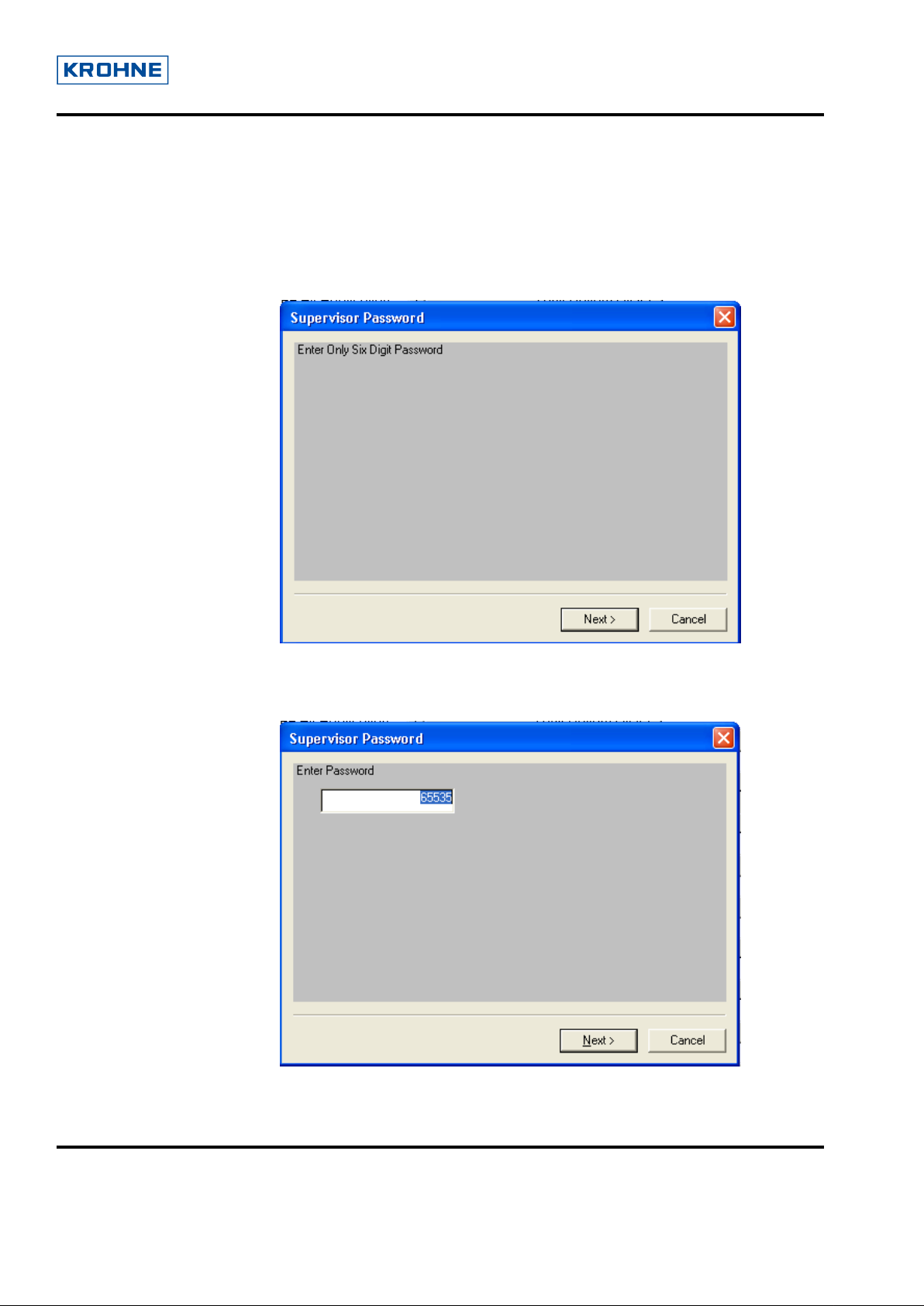
On clicking Supervisor it shows the following screen.
Note: Before accessing this menu user needs to select the “configuration variables” for
synchronization of all device parameters and for proper validation of the device parameters.
On clicking next, it shows the following window, which asks user to enter the Supervisor
Password with the default value as 65535.
© 2006 KROHNE SAS 26103 Romans (France) Page 4 of 34
Page 5
User Guide for Optiwave (FMCW) DD of AMS
Dev Rev-01, DD Rev-02
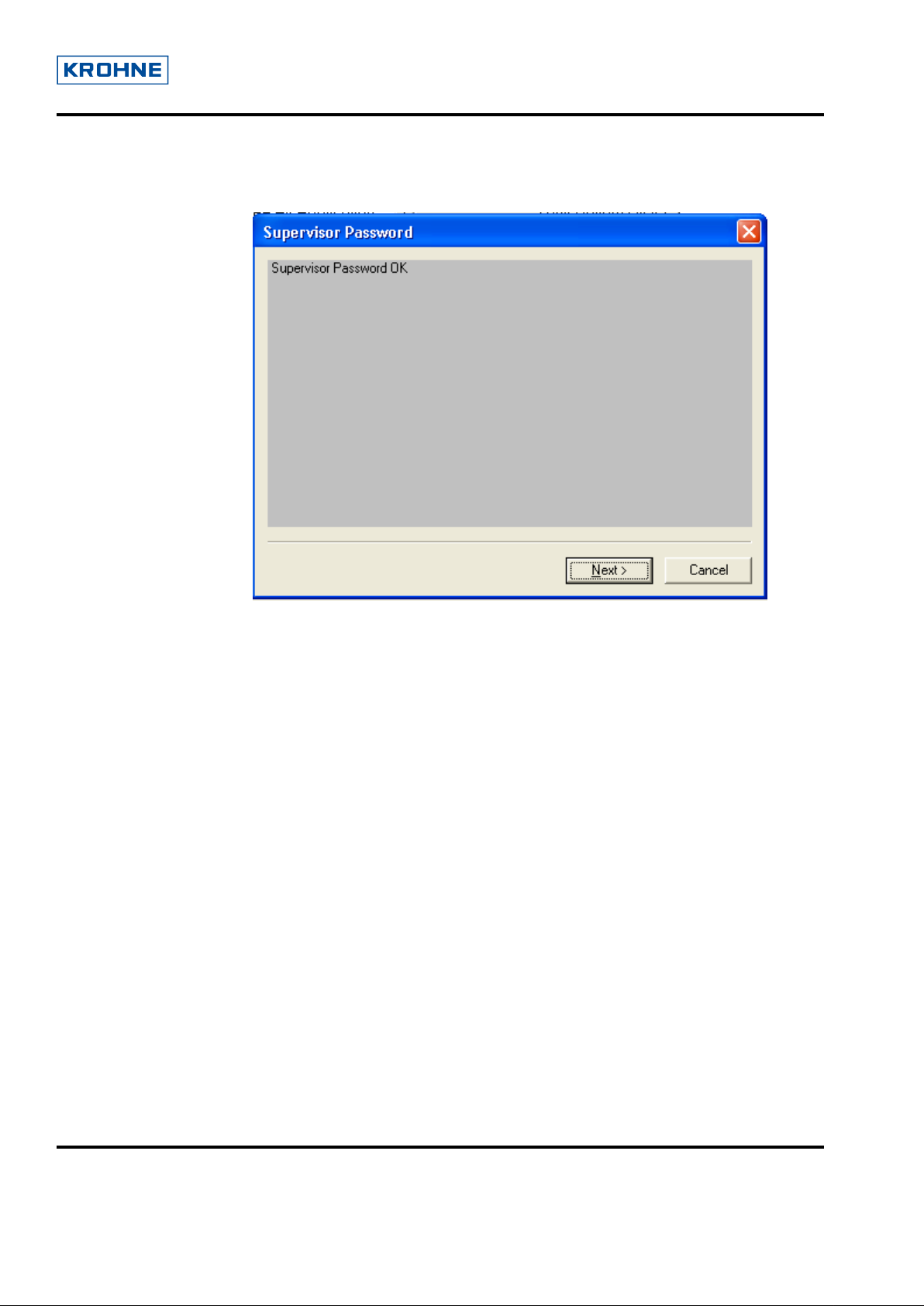
After entering the valid password and clicking next, it shows the following screen:
For success: “Supervisor Password OK”
For invalid password: “Supervisor Password Invalid”
3.1.3 Service Password
See “Supervisor Password” method
© 2006 KROHNE SAS 26103 Romans (France) Page 5 of 34
Page 6
User Guide for Optiwave (FMCW) DD of AMS
Dev Rev-01, DD Rev-02
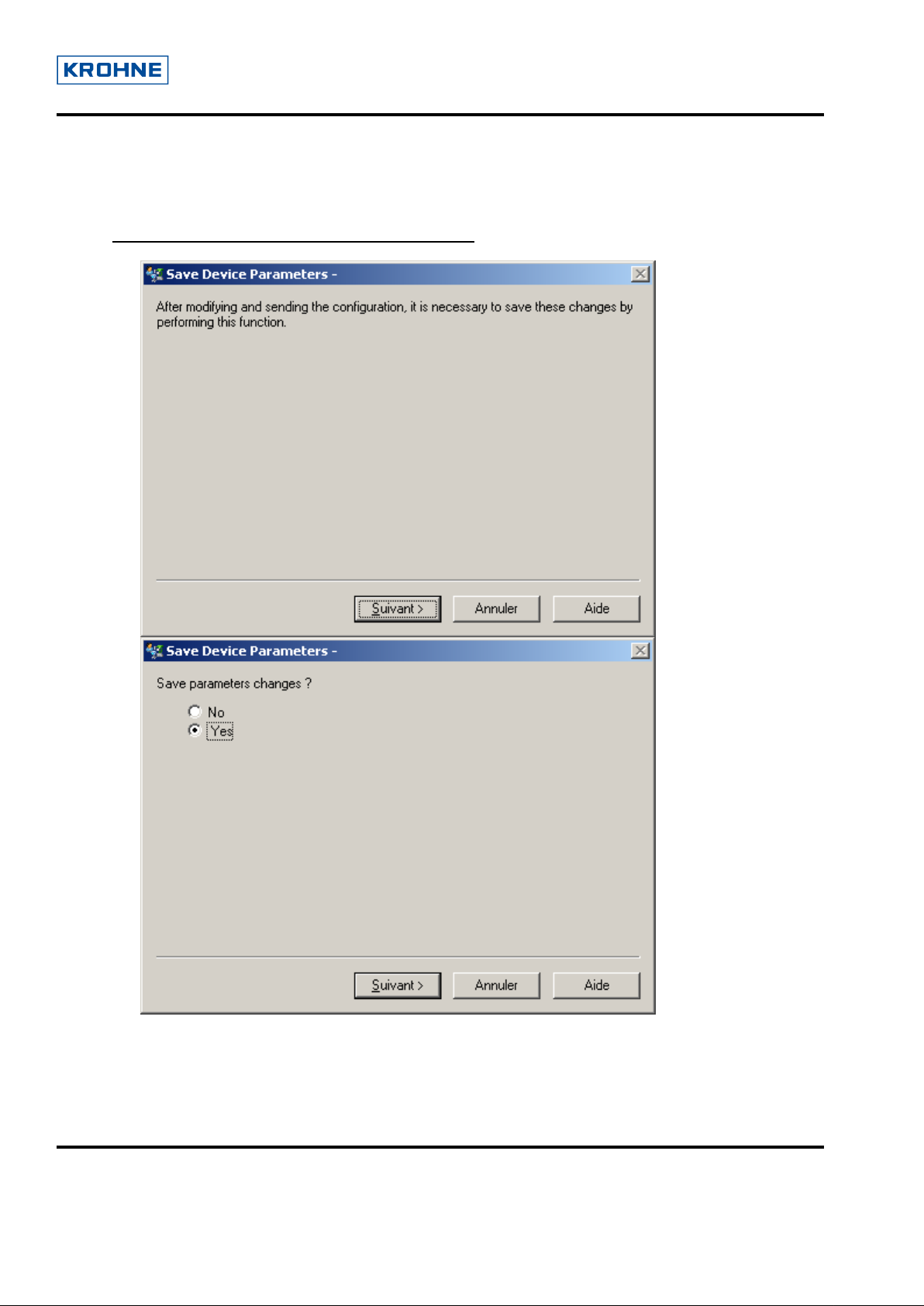
3.2 Save Device Parameters
ATTENTION: This is a very important method.
Each time the device configuration is modified
method. Otherwise the modifications will not be taking into account.
(after applying changes) it is necessary to execute this
© 2006 KROHNE SAS 26103 Romans (France) Page 6 of 34
Page 7
User Guide for Optiwave (FMCW) DD of AMS
Dev Rev-01, DD Rev-02
3.3 Diagnostic and Test
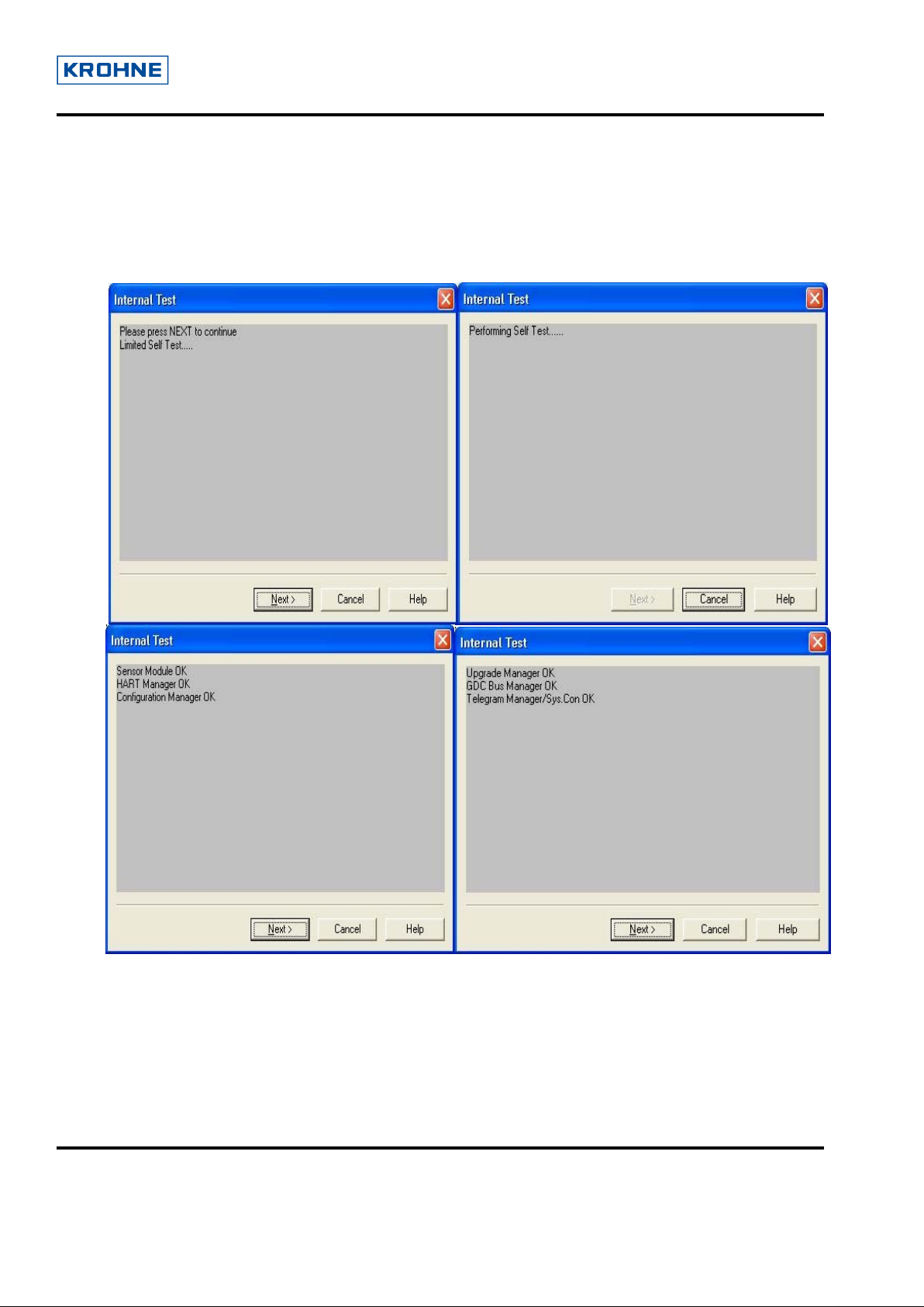
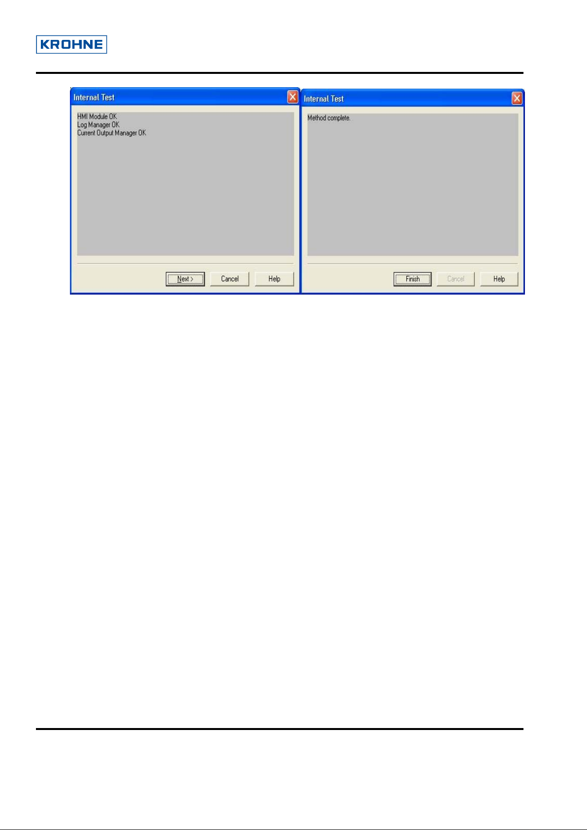
3.3.1 Internal Test
On selecting “Internal Test” from the main menu, device performs self test and displays results as
following:
© 2006 KROHNE SAS 26103 Romans (France) Page 7 of 34
Page 8
User Guide for Optiwave (FMCW) DD of AMS
Dev Rev-01, DD Rev-02
© 2006 KROHNE SAS 26103 Romans (France) Page 8 of 34
Page 9
User Guide for Optiwave (FMCW) DD of AMS
Dev Rev-01, DD Rev-02
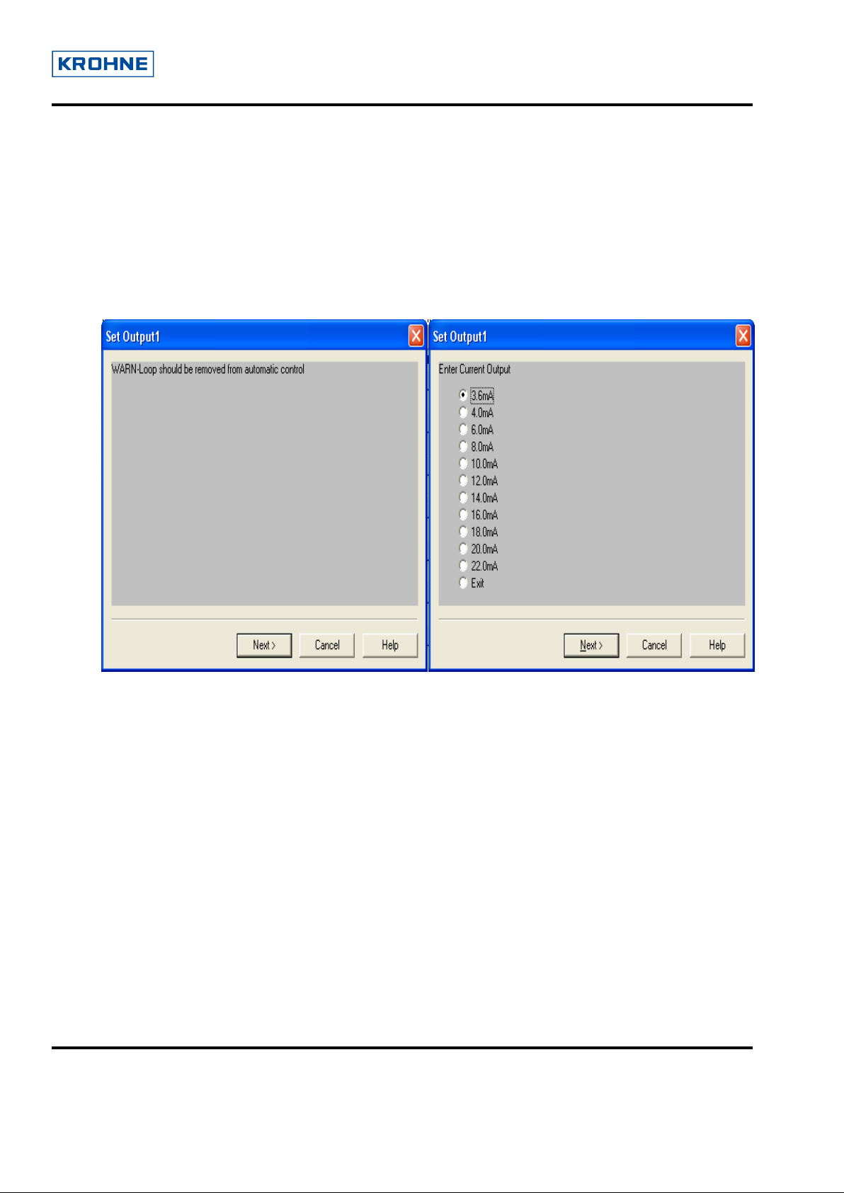
3.3.2 Set Output1
It allows fixing different values to the current output1 . It is a test mode. User can check the loop
currents in output1 and output2. The list of currents are displayed in the list box.
Once the appropriate current is selected the loop current is fixed to that current value. Check the loop
current by ammeter and validates the current as selected from the device. The loop current exits from
the current mode after clicking on 'Exit' or 'Cancel' from the method.
© 2006 KROHNE SAS 26103 Romans (France) Page 9 of 34
Page 10
User Guide for Optiwave (FMCW) DD of AMS
Dev Rev-01, DD Rev-02
3.3.3 Set Output2
See “Set Output1”
3.4 Calibration
The Calibration can be done for the output1 and output2. Here the following sections will be
describes the detailed about the calibration screen options for the output1 lower and upper.
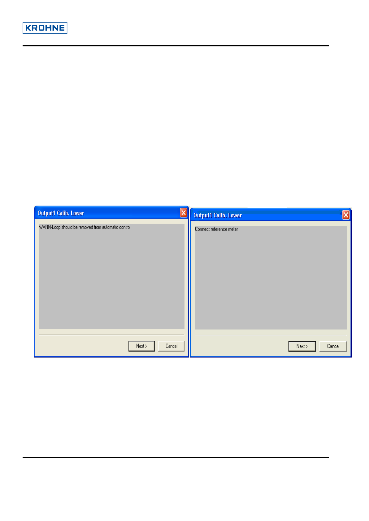
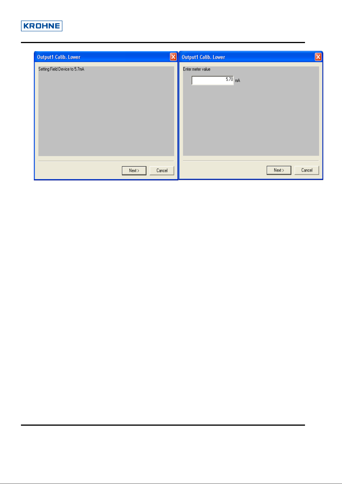
3.4.1 Output1 Lower
In Output1 Lower, it allows user to trim current output1.
The user starts to fix the current to 4mA, after entering the current value he reads on a voltmeter,
this value is sent to the device. This method allows adjusting to have exactly the good current
value of output1 loop.
© 2006 KROHNE SAS 26103 Romans (France) Page 10 of 34
Page 11
User Guide for Optiwave (FMCW) DD of AMS
Dev Rev-01, DD Rev-02
© 2006 KROHNE SAS 26103 Romans (France) Page 11 of 34
Page 12

User Guide for Optiwave (FMCW) DD of AMS
Dev Rev-01, DD Rev-02
3.4.2 Output1 Upper
In Output1 Upper, user allows to trim current output1.
The user start to fix the current to 20mA, after entering the current value he read on a voltmeter,
this value is sent to the device. This method allows adjusting to have exactly the good current
value of output1 loop.
© 2006 KROHNE SAS 26103 Romans (France) Page 12 of 34
Page 13

User Guide for Optiwave (FMCW) DD of AMS
Dev Rev-01, DD Rev-02
© 2006 KROHNE SAS 26103 Romans (France) Page 13 of 34
Page 14

User Guide for Optiwave (FMCW) DD of AMS
Dev Rev-01, DD Rev-02
3.5 Tables
3.5.1 Volume/Mass Table
Select “Conversion Table” will display all the entries of conversion table in ‘2 x 2’ Format.
Display will be in following steps
1. After Displaying all entries:
If yes is selected, it permits user to edit or add new entries.
© 2006 KROHNE SAS 26103 Romans (France) Page 14 of 34
Page 15

User Guide for Optiwave (FMCW) DD of AMS
Dev Rev-01, DD Rev-02
2. Selection of Next Entry will show next entry Level to edit, after clicking Enter, Volume/Mass is
displayed for next Entry to edit. After editing Level & Volume/Mass for current entry, above shown
menu is displayed again.
3. Selection of Previous Entry will show previous entry Level to edit, after clicking next, Volume/Mass
is displayed for previous Entry to edit. After editing Level & Volume/Mass for current entry, above
shown menu is displayed again.
4. Selection of Entry Number will take Entry Number from user and will display that entry Level to edit,
after clicking next, Volume is displayed for given Entry number to edit. After editing Level & Volume
for entry, above shown menu is displayed again.
If Entered Entry Number is greater than Entries+1, Entry Number is made equal to Number of Entries
+ 1.
If Yes is entered, table with edited values is stored in to the Device (If table entered is monotonous).
Note: All values entered for Level and Volume should be in increasing order with Entry numbers
(Corresponding warnings are displayed). Level value entered can not exceed Tank Height.
© 2006 KROHNE SAS 26103 Romans (France) Page 15 of 34
Page 16

User Guide for Optiwave (FMCW) DD of AMS
Dev Rev-01, DD Rev-02
3.5.2 Linearisation Table
Above explained steps for volume/mass Table are to be followed, with Distance Real, Distance Device
instead of Level and Volume respectively.
The editing and displaying wizard is the same as that of volume/mass table .The display of the
Linearisation table is shown below
Note : The length and volume/mass unit can be changed from installation plate2
© 2006 KROHNE SAS 26103 Romans (France) Page 16 of 34
Page 17

User Guide for Optiwave (FMCW) DD of AMS
Dev Rev-01, DD Rev-02
3.5.3 Delete Tables
Delete tables allow user to delete the volume/mass and Linearisation tables entirely.
© 2006 KROHNE SAS 26103 Romans (France) Page 17 of 34
Page 18

User Guide for Optiwave (FMCW) DD of AMS
Dev Rev-01, DD Rev-02
3.6 Empty Spectrum Recording
The following figure in order illustrates the steps for Empty Spectrum Recording.
© 2006 KROHNE SAS 26103 Romans (France) Page 18 of 34
Page 19

User Guide for Optiwave (FMCW) DD of AMS
Dev Rev-01, DD Rev-02
After validating all the depending parameters required for the empty spectrum process, It starts the recording,
displaying the current status of it.
© 2006 KROHNE SAS 26103 Romans (France) Page 19 of 34
2
Page 20

User Guide for Optiwave (FMCW) DD of AMS
Dev Rev-01, DD Rev-02
3.7 Reset
There are three types of reset. For the security reasons it re-ensures for the reset.
3.7.1 Factory Reset
In the Factory Reset, the device or configurations are set to the factory default values.
© 2006 KROHNE SAS 26103 Romans (France) Page 20 of 34
Page 21

User Guide for Optiwave (FMCW) DD of AMS
Dev Rev-01, DD Rev-02
3.7.2 Customer Reset
This makes the parameter values to user default values.
© 2006 KROHNE SAS 26103 Romans (France) Page 21 of 34
Page 22

User Guide for Optiwave (FMCW) DD of AMS
Dev Rev-01, DD Rev-02
3.7.3 Device Reset
It is used to restart the device.
© 2006 KROHNE SAS 26103 Romans (France) Page 22 of 34
Page 23

User Guide for Optiwave (FMCW) DD of AMS
Dev Rev-01, DD Rev-02
3.8 Configuration Variables
To view Help for each configuration parameter, first click on Help button on toolbar & then click on
the parameter for which help is to be viewed.
3.8.1 Installation Parameters1
This plate consists of the editable parameters of the device like Tank Type, Tank Height etc. In this
plate some of the parameters are dependent on other parameters like Measuring Range, Tank Height,
etc is dependent on Tank Type, Stillwell Height, Stillwell Diameter depends upon the Application
Type which gets disabled.
On editing particular parameter it gets yellow in color and Apply button get
activated. On clicking, Apply Button the new value gets stored in the parameter.
© 2006 KROHNE SAS 26103 Romans (France) Page 23 of 34
Page 24

User Guide for Optiwave (FMCW) DD of AMS
Dev Rev-01, DD Rev-02
3.8.2 Installation Parameters2
It allows user to change the unit of configuration parameters.
© 2006 KROHNE SAS 26103 Romans (France) Page 24 of 34
Page 25

User Guide for Optiwave (FMCW) DD of AMS
Dev Rev-01, DD Rev-02
3.8.3 Output Selection
It allows user to change the Primary Output Function, Secondary Output Function, Tertiary Output
Function and Fourth Output function. Beside this it provides detail’s of primary and secondary output
as differentiated by the group box namely output1 and output2.
© 2006 KROHNE SAS 26103 Romans (France) Page 25 of 34
Page 26

User Guide for Optiwave (FMCW) DD of AMS
Dev Rev-01, DD Rev-02
3.8.4 Primary Output Setting
It allows user to change the upper and lower limit of the parameters set in the output selection plate for
the primary output function. The units of all these parameters are shown as set in the installation
plate2. Since only one pair of parameters can be set to the primary output function, hence the rest of
the parameters are disabled.
© 2006 KROHNE SAS 26103 Romans (France) Page 26 of 34
Page 27

User Guide for Optiwave (FMCW) DD of AMS
Dev Rev-01, DD Rev-02
3.8.5 Secondary Output Setting
It allows user to change the upper and lower limit of the parameter set in the output selection plate for
the secondary output function.
© 2006 KROHNE SAS 26103 Romans (France) Page 27 of 34
Page 28

User Guide for Optiwave (FMCW) DD of AMS
Dev Rev-01, DD Rev-02
3.8.6 Service
It allows user to view all the service parameters, calibration parameters and the service information.
The service parameters are only activated by the service password.
© 2006 KROHNE SAS 26103 Romans (France) Page 28 of 34
Page 29
User Guide for Optiwave (FMCW) DD of AMS
Dev Rev-01, DD Rev-02
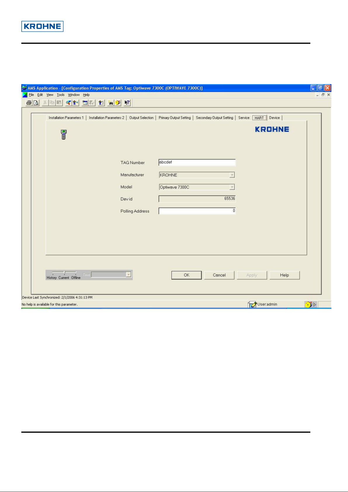
3.8.7 HART
It shows all the hart related parameters viz: manufacturer name, model name etc.
© 2006 KROHNE SAS 26103 Romans (France) Page 29 of 34
Page 30

User Guide for Optiwave (FMCW) DD of AMS
Dev Rev-01, DD Rev-02
3.8.8 Device
It shows the device specific information. This plate doesn’t require any authentication. All the
parameters can be viewed with no password.
© 2006 KROHNE SAS 26103 Romans (France) Page 30 of 34
Page 31

User Guide for Optiwave (FMCW) DD of AMS
Dev Rev-01, DD Rev-02
3.9 Process Variable
The Process Variables are displayed with magnitude and its corresponding unit along with upper & lower
limits. Four process variables are active on a single screen depending on the Output function setting.
Primary Output Function, Secondary Output Function, Tertiary Output Function, and Fourth Output Function
are used to set Primary Process Variable, Secondary Process Variable, Tertiary Process Variable, & Fourth
Process Variable respectively.
If “Level” is set as Primary Output Function, then “Level” is displayed as a Primary Process Variable &
respective current, percentage value for level is also displayed in below process variable face plate.
© 2006 KROHNE SAS 26103 Romans (France) Page 31 of 34
Page 32

User Guide for Optiwave (FMCW) DD of AMS
Dev Rev-01, DD Rev-02
3.10 Device Diagnostic
It contains the status of the device.
© 2006 KROHNE SAS 26103 Romans (France) Page 32 of 34
Page 33

User Guide for Optiwave (FMCW) DD of AMS
Dev Rev-01, DD Rev-02
4 Status Meaning
Status Message
Supervisor Password OK Entered password for Supervisor rights is
correct.
Supervisor Password Invalid Entered password for Supervisor rights is
incorrect.
Simulation Service Password OK Entered password for Service rights in
Simulation mode is correct.
Service Password Invalid
Entered password for Service rights is
incorrect.
Service Password OK Entered password for Service rights is
correct.
Simulation Supervisor Password OK
Dependency failure
Update not possible
Reading data from device
Dependency Warning Message
Entered password for Supervisor rights in
Simulation mode is correct.
It appears if the dependency of the
parameter being modified is failed.
It appears if read only parameter is
modified.
It appears when the entries of table being
read by the device.
It appears if the variable is modified and is
dependent on other variables. Such
scenario could violate its normal operation.
Max range failure When the entered value is more than its
maximum allowed value.
Min range failure When the entered value is less than its
minimum allowed value.
Table entered is not monotonous
Device busy
If the entered value is less than the next
entry.
Appears when the device is busy. Normally
it appears when the device is in search
mode or if it is executing a function.
Access Restricted
This message appears if we try to modify a
read only parameter.
Invalid Section You have selected a non valid item.
Too Few Bytes Received There are not enough bytes received.
Invalid Command Request Requested command is invalid.
Value out of range
Exceed precision
This occurs if the entered value is out of
range for that parameter.
If the decimal value entered exceeds its
range.
Meaning
© 2006 KROHNE SAS 26103 Romans (France) Page 33 of 34
Page 34

User Guide for Optiwave (FMCW) DD of AMS
Dev Rev-01, DD Rev-02
Illegal character If any invalid character is entered.
Max range failure occurred writing level
20mA.Restore device value
It appears if entered Value for 20mA is
out of range.
Method is currently invalid It appears if access right is not
5 HART® Communicator 375 (HC375)
5.1 Offline Restriction
In order to transfer an Offline configuration to the device the Service parameter “Supervisor
Password Enable” (C.5.2.0)
In case this parameter has got the value “YES” the configuration is not transferred successfully to the
device even if we don’t see any error messages!
must be set to “NO”.
5.2 Save Device Parameters
ATTENTION: This is a very important method.
Each time the device configuration is modified
method. Otherwise the modifications will not be taking into account.
This method is only accessible in case the supervisor or service password method has been executed.
(after sending new values) it is necessary to execute this
© 2006 KROHNE SAS 26103 Romans (France) Page 34 of 34
 Loading...