

Page 1
● Easy to install
● Low-cost signal converter,
measuring error < 0.5% of the measured value
● Easy user-friendly operation
● Self-monitoring feature to rule out errors in operation
● Low power consumption
IFC 010
Signal Converter
for electromagnetic flowmeters
GR
©
KROHNE 04/2003 7.02347.22.00
Variable area flowmeters
Vortex flowmeters
Flow controllers
Electromagnetic flowmeters
Ultrasonic flowmeters
Mass flowmeters
Level measuring instruments
Communications technology
Engineering systems & solutions
Switches, counters, displays and recorders
Heat metering
Pressure and temperature
Page 2
IFC 010
Signal Converter
for electromagnetic flowmeters
Standard-setting technology
● µP-controlled signal converter with digital signal processing
ensures reliability and long-time stability
● High-speed signal conversion system (patented) allows flowmeter
application even in difficult cases
● Modular signal converter, low-cost basic version without display or
control panel, easy to set and document with every DOS-PC (notebook) and KROHNE software, error-free
● can be optionally fitted with local display and control panel
● terminals and all signal converter modules pluggable, easily
replaceable without recalibration or resetting
● plus all the numerous functions:
- current, pulse and status indication outputs
- flow measurement in both directions
- low-flow cutoff
- limit signalling or direction identification
- volume flow counting via passive, galvanically
- isolated pulse output
● available for AC or DC voltage operation
2
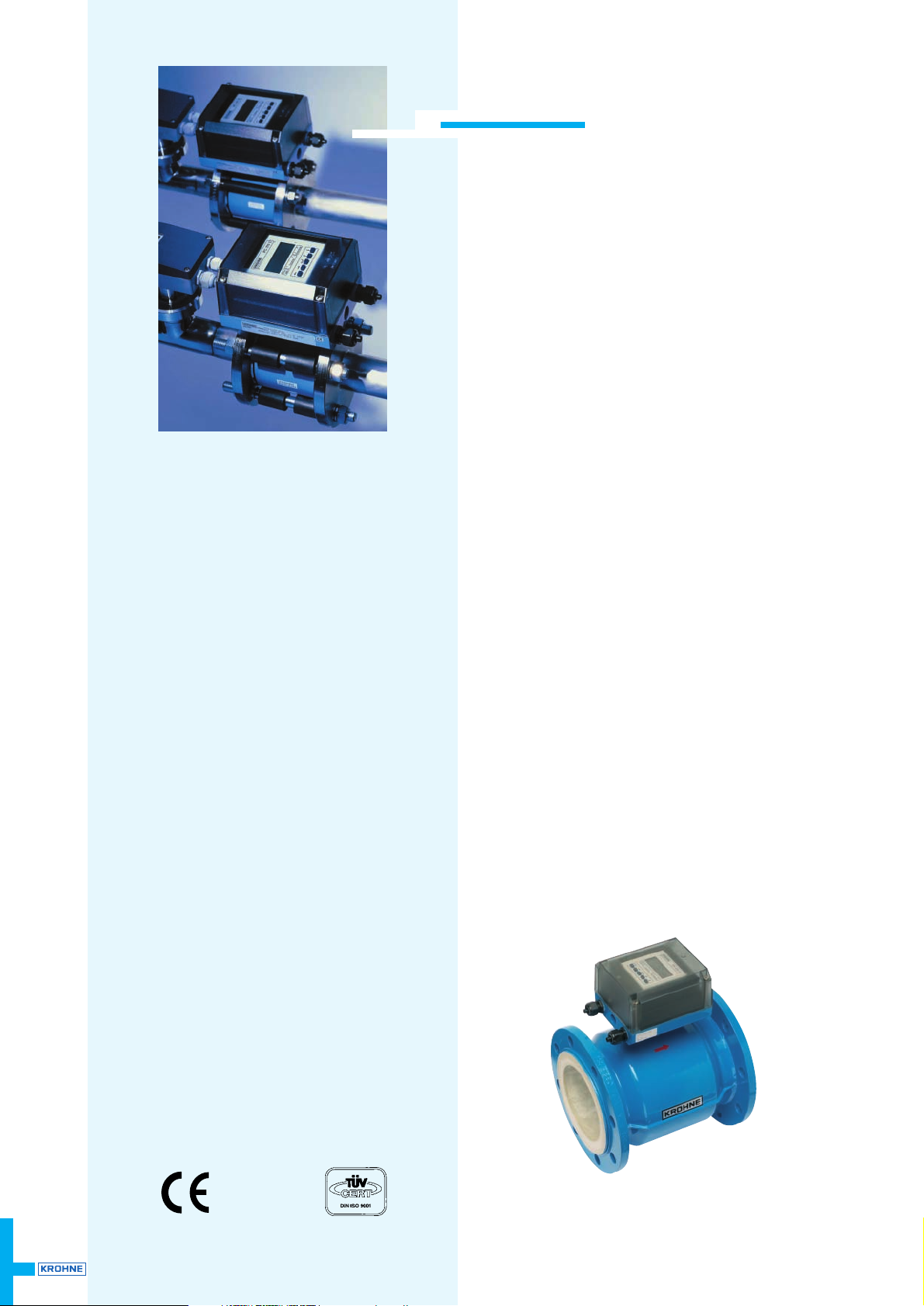
The modular KROHNE system will have the
right electromagnetic flowmeter for your
specific application – right from both the
flowmetering and the economic viewpoint.
Available versions
● IFC 010 _/B
signal converter without local display
and control elements
( B = basic version). All operating data
factory-set to your specifications.
For control and settings via DOS-PC, RS
232 adapter including PC software is
available as option.
● IFC 010 _/D
signal converter with local display and
control elements (D). All operating data
factory-set to your specifications.
Calibrated on EN 17 025
accredited calibration rigs,
accuracy of calibration better
than 99.97% of the measured value
Page 3
IFC 010 3
IFC 010
The modular KROHNE system with the IFC 010 IMoCom signal converter
The IFC 010 signal converter is compatible with all KROHNE primary heads.
Integral systems (K): Primary head and signal converter form a single unit and are solidly
connected.
Remote systems (F): Primary head and signal converter are remote units and electrically
connected by signal and field current cables.
Full data of the primary heads (IFS .... .) are specified in the relevant Data Sheets:
ALTOFLUX ..... / AQUAFLUX ..... / ECOFLUX ..... / PROFIFLUX ..... / VARIFLUX .....
Teflon® is a registered trademark of Du Pont.
Integral systems Remote systems Characterization of primary heads
with regedly mounted IFC 010 K Primary heads System with IFC 010 F Meter size Flowtube / Connection
ECOFLUX IFM 1010 K ECOFLUX IFS 1000 F ECOFLUX IFM 1010 F DN 10-150 Teflon®-PFA liner,
3
/8”-6” flangeless design
AQUAFLUX 010 K AQUAFLUX F AQUAFLUX 010 F DN 10-1000 Hard rubber liner
3
/8”-40” (≥ DN 25 / ≥ 1”),
flanged design
ALTOFLUX IFM 4010 K ALTOFLUX IFS 4000 F ALTOFLUX IFM 4010 F DN 10-1000 e.g. Teflon®-PFA liner,
3
/8”-40” flanged design
PROFIFLUX IFM 5010 K PROFIFLUX IFS 5000 F PROFIFLUX IFM 5010 F DN 2.5-100 fused aluminium oxide tube,
1
/10”-4” flangeless design
VARIFLUX IFM 6010 K VARIFLUX IFS 6000 F VARIFLUX IFM 6010 F DN 10-80 Teflon®-PFA liner,
3
/8”-3” food-grade and sterile
connections
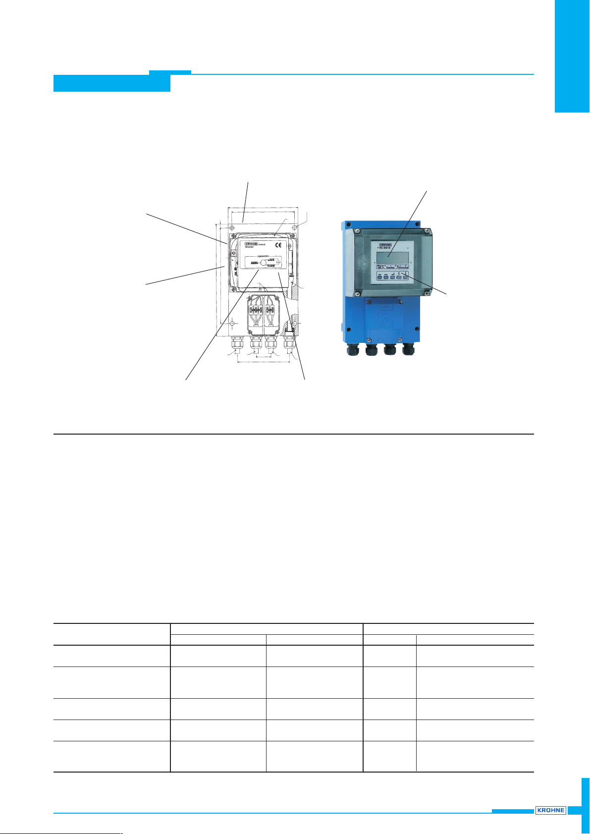
Low maintenance requirement, electronics unit easy and quick to replace,
no recalibration needed
Large, high-contrast LC display (option)
5-key keypad, easy
user-friendly operation (option)
Many different (scaled)
outputs available
IMoCom plug connectors for operating,
saving, documenting and downloading
all setting data
Portable operating data EEPROM
Low-cost signal converter, measuring
error < 0.5% of the measured value
Highlights
Page 4

IFC 010
IFC 010
4
Flowrate for Q = 100 % adjustable 6 liters/h to 33000 m3/h or 0.4 to 156000 US gallons/min, corresponding to flow velocity
v = 0.3 to 12 m/s or 1 to 40 ft/s
Unit adjustable m
3
/h, liters/s or US-gallons/min, and 1 user-defined unit e. g. m3/min or US million gallons per day
Full-scale range Q
100%
Reference conditions
Product Water, 10 to 30°C/50 to 86 °F
Electrical conductivity > 300 µS/cm (µmho/cm)
Power supply (line voltage) U
N
(± 2 %)
Ambient temperature 20 to 22°C/68 to 71.6°F
Warm-up time 30 minutes
Straight inlet run > 10 x DN DN =
Straight outlet run > 03 x DN
}
meter size
Primary heads properly grounded and centered
Error limits for complete system at reference conditions
Pulse output
± F Error in % of flowrate (actual value): Curve A: DN 10 – 600 /
3
/8” – 24”
v ≥ 0.4 m/s or ≥ 1.3 ft/s: ± 0.5 % of measured value
v < 0.4 m/s or < 1.3 ft/s: ± 0.002 m/s or 0.0066 ft/s
Curve B: DN 2.5 – 6 /
1
/10”– 1/4” (PROFIFLUX) and DN 700 – 1000 / 28” – 40”
v ≥ 0.25 m/s or ≥ 0.8 ft/s: ± 0.8 % of measured value
v < 0.25 m/s or < 0.8 ft/s: ± 0.002 m/s or 0.0066 ft/s
Q Actual flowrate
Q
F
Flow for error limit vF = 0.25 m/s or 0.8 ft/s
v Flow velocity in m/s and ft/s
v
F
Flow velocity in m/s and ft/s at QF
Current output same as above error limit for pulse output plus...
0 to 20 mA:
± 0.05 %
4 to 20 mA:
± 0.062 %
}
of full-scale range in each case
All KROHNE signal converters undergo burn-in tests, duration minimum 20 hours at varying ambient temepratures –20 to +60°C / –4 to +140°F.
Function and accuracy are controlled by computers.
3
2
1
0.8
0.5
v
m/s
(ft / sec)
0.25
(0.8)
0.4
(1.3)
0.5
(1.6)
0.75
(2.4)1 (3.2)
10
(33)
11
(36)
12
(40)
B
A
Q
F
Q
F
e F
%
Flow tables
v = flow velocity in m/s
Meter size Full-scale range Q
100% in m
3
/h
DN v = 0.3 m/s v = 1 m/s v = 12 m/s
mm inch (minimum) (maximum)
2.5
1
/10 0.0053 0.0177 0.2121
4
1
/8 0.0136 0.4520 0.5429
6
1
/4 0.0306 0.1018 1.222
10
3
/8
0.0849 0.2827 3.392
15
1
/2 0.1909 0.6362 7.634
20
3
/4 0.3393 1.131 13.57
25 1 0.5302 1.767 21.20
32 – 0.8686 2.895 34.74
40 11/2 1.358 4.524 54.28
50 2 2.121 7.069 84.82
65 – 3.584 11.95 143.3
80 3 5.429 18.10 217.1
100 4 8.483 28.27 339.2
125 – 13.26 44.18 530.1
150 6 19.09 63.62 763.4
200 8 33.93 113.1 1357
250 10 53.02 176.7 2120
300 12 76.35 254.5 3053
400 16 135.8 452.4 5428
500 20 212.1 706.9 8482
600 24 305.4 1018 12215
700 28 415.6 1385 16625
800 32 542.9 1810 21714
900 36 662.8 2290 26510
1000 40 848.2 2827 33929
v = flow velocity in ft/s
Meter size Full-scale range Q
100% in US gallons/min
DN v = 1 ft/s v = 40 ft/s
mm inch (minimum) (maximum)
2.5
1
/10 0.0245 0.979
4
1
/8 0.0383 1.530
6
1
/4 0.1530 6.120
10
3
/8
0.3735 14.93
15
1
/2 0.8405 33.61
20
3
/4 1.494 59.75
25 1 2.334 93.34
32 – 3.824 153.0
40 11/2 5.979 239.0
50 2 9.339 373.5
65 – 15.78 630.9
80 3 23.90 955.6
100 4 37.35 1493
125 – 58.38 2334
150 6 84.05 3361
200 8 149.43 5975
250 10 233.4 9334
300 12 336.2 13442
400 16 597.9 23899
500 20 933.9 37345
600 24 1345 53781
700 28 1919 76760
800 32 2507 100272
900 36 3173 126904
1000 40 3917 156672
Page 5

IFC 010 5
IFC 010
Technical data
1000
P
100%
[Hz]
Versions
B - version without display / control unit (basic version)
D - version with display / control unit
Add-on equipment (option) - CONFIG-software and RS 232-adapter for control via MS-DOS-PC,
connection to IMoCom interface
- Hand-Held-Terminal for control of blind versions
Current output
Function – all operating data configurable, galvanically isolated
Current 0 – 20 mA or 4 – 20 mA
Active output load max. 500 ohms
Passive output external voltage: 15 ... 20 V DC 20 ... 32 V DC
load: min. ... max. 0 ... 500 Ω 250 ... 750 Ω
Error identification 0 / 3.6 / 22 mA
Forward/reverse measurement direction identified via status output
Pulse output
Function – all operating data settable
– galvanically isolated
– digital pulse division, interpulse period non-uniform, therefore if
– frequency meters connected allow for minimum counting interval:
gate time, totalizer ≥
Pulse rate for Q = 100 %
Standard 10, 100 or 1000 pulses per second (= Hz), fixed or optionally adjustable in pulses
per liter, m3or US gallons
Special version (option) up to 10 kHz scaling
Active output: connection: electronic totalizer (EC)
internal voltage: approx. 15 V DC, from current output
load rating: I
max
< 23 mA when operated without current output
I
max
< 3 mA when operated with current output
Passive output: connection electromechanical (EMC) or electronic (EC) totalizers
external voltage: U
ext
≤ 30 V DC / ≤ 24 V AC
load current: I
max
≤ 150 mA / special version 10 kHz: f ≤ 1 kHz I
max
≤ 150 mA
f > 1 kHz I
max
≤ 30 mA
Pulse width 50, 100, 200, 500 ms or 1 s, choice with frequencies below 10 Hz
Forward/reverse measurement direction identified via status indication output
Status output (passive)
Function configurable as indicator for flow direction, errors or trip point
Connection external voltage: extern, U
ext.
≤ 30 V DC / ≤ 24 V AC
load current: I
max
≤ 150 mA
Time constant 0.2 to 99.9 seconds, settable in increments of 0.1 second
Low-flow cutoff
cutoff ”on“ value: 1 to 19 %
cutoff ”off” value: 2 to 20 %
}
of Q100%, adjustable in 1 % increments
Local display (D versions only) 3-line LCD
Display functions actual flowrate, forward, reverse and sum totalizers (7-digit)
or 25-character bar graph with percent display and status messages
Display units:actual flowrate configurable in liter/s, m3/h, US gallons/min or user-defined unit,
e. g. hectoliter/day or US million gallons/day
totalizers liter, m3or US gallons and 1 user-defined unit
(e.g. hectoliter), choice of overflow time
Language of plain texts English, German, French, others on request
Display: 1st (top) line 8-character, 7-segment numeral and sign display,
symbols for key acknowledgement
2nd (middle) line 10-character, 14-segment text display
3rd (bottom) line 6 markers ▼ to identify display
Power supply 1. AC-Version 2. AC-Version 3. AC-Version DC-Version
Standard Option Option Option
1. Rated voltage 230 / 240 V 200 V 48 V 24 V
tolerance band 200 - 260 V 170 - 220 V 41 - 53 V 11 - 32 V
2. Rated voltage 115 / 120 V 100 V 24 V tolerance band 100 - 130 V 85 - 110 V 20 - 26 V -
Frequency 48 - 63 Hz - - Power consumption (incl. primary head) approx. 5 VA approx. 4.5 W
When connected to a functional extra-low voltage, 11 - 32 V DC,
protective separation (PELV) must be ensured
(VDE 0100 / VDE 0106 and IEC 364 / IEC 536)
Housing
Material polyamide (PA) and die-cast aluminium
Protection category
(IEC 529/EN 60529) IP 67 equivalent to NEMA 6
The responsibility as to the suitability, intended use and corrosion-resistance of the materials used in their
construction rests solely with the purchaser.
Full primary head (flowmeter) data are specified in the relevant Data Sheets.
Page 6

IFC 010
IFC 010
6
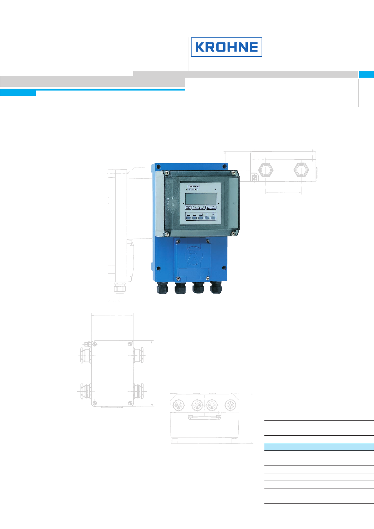
Dimensions and weights
Housing for intermediate connection box ZD
for product temperature > 150 °C or 302 °F
Dimensions in mm and (inches)
Weight approx. 0.5 kg or 1.1 lbs
IFC 010 F signal converter
Dimensions in mm and (inches)
Weight approx. 3.8 kg (8.4 lb)
120 (4.72”)
34 (1.34”)
220 (8.66”)
258 (10.16”)
160 (6.30”)
80 (3.15”)
dia. 9 (3x)
(dia. 0.38”)
27.5
(1.08”)
116 (4.57”)
80 (3.15”)
57 (2.24”)
125 (4.92”)
68 (2.68”)
22
(0.87”)
Page 7

IFC 010 7
IFC 010
IFC 010 Electrical connection
Power supply and outputs
protective conductor
functional ground
}
Current output
passiv
e
active
Pulse and status output
passiv
e active
Electrical connection in conformity with
VDE 0100 ”Regulations governing heavycurrent installations with mains voltages
up to 1000 V” or equivalent national
standard.
If to be connected to a functional extralow voltage source (24 V DC / AC and 48
V AC) protective separation in conformity
with VDE 0100, Part 410, or equivalent
national standard, must be ensured.
AC: 100–240 V
AC: 24/48 V
DC: 24 V
Power
for
internal
use only
I current outputs
P pulse output
S status indication output
Outputs
U-clamp terminal
PE
FE
FE
e. g.
indicator
A
Technical Data of the pulse output see page 8.
Length (L) of signal cable A
dependent on electrical conductivity k
IFC 010 F signal converter
↔
primary head
Connection diagram
The figures in brackets refer to the stranded drain wires for the shields,
see sectional drawings of signal cable on page 8.
IFC 010 F
Primary head
FE
Field power supply cable C (not supplied)
A
A
Length Cable type, single shielding
0 - 150 m / 5 to 500 ft 2 x 0.75 mm2Cu / 2 x 18 AWG
150 - 300 m / 1000 to 1600 ft 2 x 1.50 mm2Cu / 2 x 14 AWG
L N
1L~ 0L~
L+ L–
Primary head Meter size Signal cable
DN mm inches
ECOFLUX IFS 1000 F 10 - 153/8-1/
2
A4
25 - 150 1 - 6 A3
AQUAFLUX F 10 - 10003/8-40 A1
ALTOFLUX IFS 4000 F 10 - 1503/8-6 A2
200 - 1000 8 - 40 A1
PROFIFLUX IFS 5000 F 2.5 - 151/10-1/
2
A4
25 - 100 1 - 4 A2
VARIFLUX IFS 6000 F 10 - 151/8-1/
2
A4
25 - 80 1 - 3 A2
Page 8

IFC 010
IFC 010
8
IFC 010 Description
The standard
● outstanding accuracy
● full set of standard equipment
● current and pulse outputs (galvanically isolated)
● status output, easy to set for numerous tasks: as
● trip point, to indicate flow direction, error messages
● IMoCom bus can be used for numerous internal and external tasks
● simplified, standard KROHNE operator control concept
● very low power consumption
1 Input amplifier
● overdrive-proof signal processing, rapidly and accurately
● digital signal processing and sequence control
● patented, high-resolution A/D converter, digitally controlled
and monitored
● high signal-to-noise ratio through low-loss field power supply
2 Field power supply
● the low-loss field power supply generates the pulsed, elec-
tronically controlled DC current for the magnetic coils of the
primary head
3 Current output
● galvanically isolated from all other groups
● converts the digital output signal from the µP 3 micro-
processor into a proportional current
4 Binary outputs
● galvanically isolated from other groups
● selectable input/output combinations
● pulse output (B1), passive FET optocouplers allow connec-
tion of electronic and electromechanical totalizers
● status output (B2) for limit value, error identification, or flow
direction in forward/reverse flow mode (F/R)
5 Display/operator control unit
(option, D Version)
● large-size illuminated LC display
● 3 keys for operator control of the signal converter
● connection to the internal IMoCom bus
● unit can be retrofitted to basic devices (B Version)
6 IMoCom bus plug connector
for connection of external control and test devices such as:
● HHT handheld terminal (option), display/operator control
unit for operation of basic versions
● adapter and CONFIG software for operation via MS-DOS PC
6
1 Stranded drain wire, 1st shield, 1.5 mm2or AWG 14
2 Insulation
3 Stranded wire 0.5 mm
2
or AWG 20
4 Special foil, 1st shield
5 Insulation
6 Mu-metal foil, 2nd shield
7 Stranded drain wire, 2nd shield, 0.5 mm
2
or AWG 20
8 Outer sheath
Signal cable A (type DS), with double shielding
Page 9

9
IFC 010
IFC 010
Ordering Code
IFC 010 Signal converter for primary heads (flowmeter)
AQUAFLUX / ECOFLUX 1000 / ALTOFLUX 4000 / PROFIFLUX 5000 / VARIFLUX 6000
 Loading...