

Page 1

OPTIFLUX
OPTIFLUX
OPTIFLUXOPTIFLUX
IECEx addendum
Supplementary instructions
Supplementary instructions
Supplementary instructions Supplementary instructions
© KROHNE 06/2010 - 7312092100 - AD OPTIFLUX IECEx R01 en
Page 2

CONTENTS
OPTIFLUX
1 Introduction 3
1.1 Safety instructions from the manufacturer ..................................................................... 3
1.1.1 Disclaimer ............................................................................................................................... 3
1.1.2 Product liability and warranty ................................................................................................ 4
1.1.3 Information concerning the documentation........................................................................... 4
1.1.4 Warnings and symbols used................................................................................................... 5
1.1.5 Manufacturer .......................................................................................................................... 5
1.2 Safety instructions for the operator................................................................................. 6
1.3 Approvals.......................................................................................................................... 7
1.4 OPTIFLUX 2000 / 4000 ...................................................................................................... 7
1.4.1 Compact versions ................................................................................................................... 7
1.5 Marking labels .................................................................................................................. 8
2 Temperature limits 9
2.1 OPTIFLUX 2000 / 4000 ...................................................................................................... 9
2.1.1 Compact versions ................................................................................................................... 9
3 Electrical connections 10
3.1 Installation instructions ................................................................................................. 10
3.2 Connections .................................................................................................................... 11
4 Maintenance and service 12
4.1 Maintenance and service................................................................................................ 12
5 Notes 13
2
www.krohne.com 06/2010 - 7312092100 - AD OPTIFLUX IECEx R01 en
Page 3

OPTIFLUX
1.1 Safety instructions from the manufacturer
1.1.1 Disclaimer
The manufacturer will not be liable for any damage of any kind by using its product, including,
but not limited to direct, indirect, incidental, punitive and consequential damages.
This disclaimer does not apply in case the manufacturer has acted on purpose or with gross
negligence. In the event any applicable law does not allow such limitations on implied warranties
or the exclusion of limitation of certain damages, you may, if such law applies to you, not be
subject to some or all of the above disclaimer, exclusions or limitations.
Any product purchased from the manufacturer is warranted in accordance with the relevant
product documentation and our Terms and Conditions of Sale.
The manufacturer reserves the right to alter the content of its documents, including this
disclaimer in any way, at any time, for any reason, without prior notification, and will not be liable
in any way for possible consequences of such changes.
INTRODUCTION 1
www.krohne.com06/2010 - 7312092100 - AD OPTIFLUX IECEx R01 en
3
Page 4

1 INTRODUCTION
1.1.2 Product liability and warranty
The operator shall bear responsibility for the suitability of the device for the specific purpose.
The manufacturer accepts no liability for the consequences of misuse by the operator. Improper
installation and operation of the devices (systems) will cause the warranty to be void. The
respective "Standard Terms and Conditions" which form the basis for the sales contract shall
also apply.
1.1.3 Information concerning the documentation
To prevent any injury to the user or damage to the device it is essential that you read the
information in this document and observe applicable national standards, safety requirements
and accident prevention regulations.
If this document is not in your native language and if you have any problems understanding the
text, we advise you to contact your local office for assistance. The manufacturer can not accept
responsibility for any damage or injury caused by misunderstanding of the information in this
document.
This document is provided to help you establish operating conditions, which will permit safe and
efficient use of this device. Special considerations and precautions are also described in the
document, which appear in the form of underneath icons.
OPTIFLUX
4
www.krohne.com 06/2010 - 7312092100 - AD OPTIFLUX IECEx R01 en
Page 5
OPTIFLUX
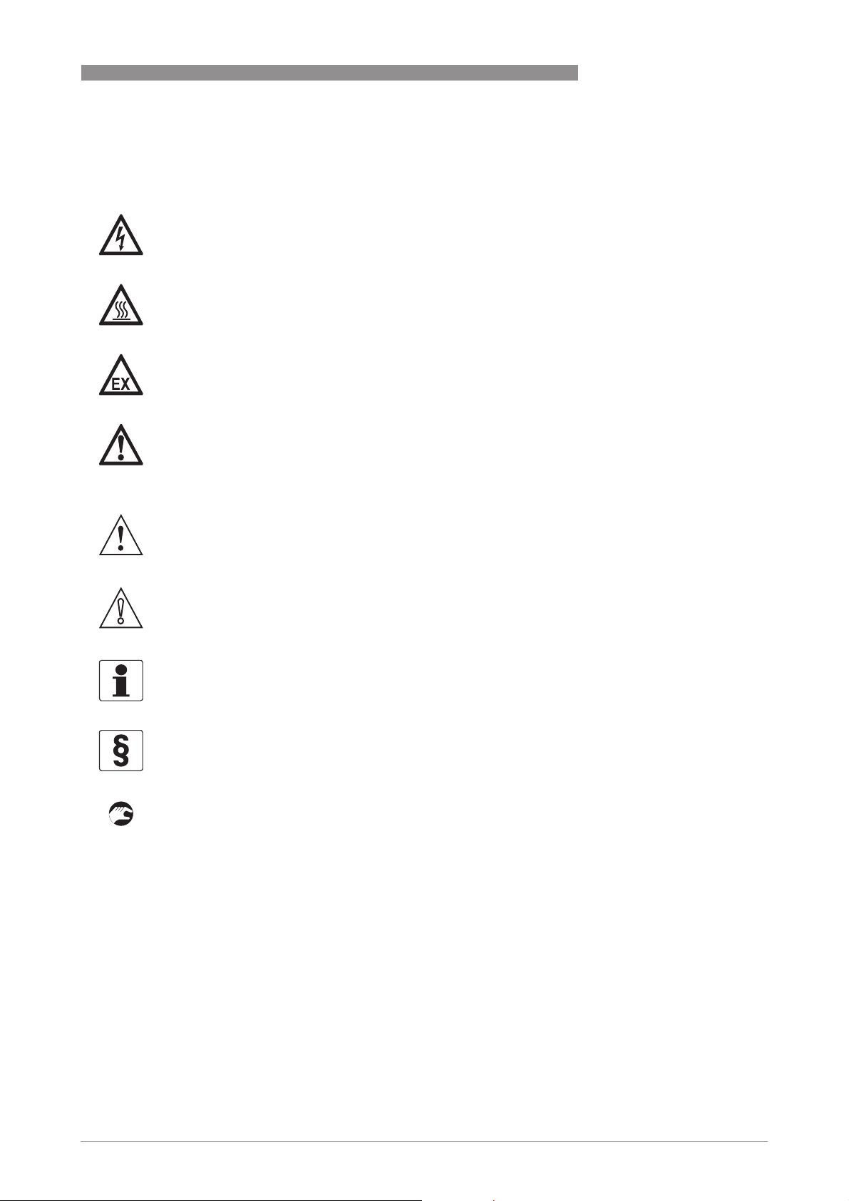
1.1.4 Warnings and symbols used
Safety warnings are indicated by the following symbols.
DANGER!
This information refers to the immediate danger when working with electricity.
DANGER!
This warning refers to the immediate danger of burns caused by heat or hot surfaces.
DANGER!
This warning refers to the immediate danger when using this device in a hazardous atmosphere.
DANGER!
These warnings must be observed without fail. Even partial disregard of this warning can lead to
serious health problems and even death. There is also the risk of seriously damaging the device
or parts of the operator's plant.
INTRODUCTION 1
WARNING!
Disregarding this safety warning, even if only in part, poses the risk of serious health problems.
There is also the risk of damaging the device or parts of the operator's plant.
CAUTION!
Disregarding these instructions can result in damage to the device or to parts of the operator's
plant.
INFORMATION!
These instructions contain important information for the handling of the device.
LEGAL NOTICE!
This note contains information on statutory directives and standards.
• HANDLING
HANDLING
HANDLINGHANDLING
This symbol designates all instructions for actions to be carried out by the operator in the
specified sequence.
i RESULT
RESULT
RESULTRESULT
This symbol refers to all important consequences of the previous actions.
1.1.5 Manufacturer
This instrument is developed and manufactured by:
KROHNE Altometer
Kerkeplaat 12
3313 LC Dordrecht
The Netherlands
www.krohne.com06/2010 - 7312092100 - AD OPTIFLUX IECEx R01 en
5
Page 6

1 INTRODUCTION
For information, maintenance or service please contact your nearest local KROHNE
representative.
1.2 Safety instructions for the operator
WARNING!
•
Do not change the device. Unauthorized changes affect the explosion safety of the devices.
•
The prescriptions and regulations as well as the electrical data described in the EC type
examination certificate must be obeyed.
•
Beside the instructions for electrical installations in non-hazardous locations according to
the applicable national standard (equivalent to HD 384 or IEC 60364, e.g. VDE 0100),
especially the regulations in EN 60079-14 "Electrical installations in hazardous locations",
equivalent national standard (e.g. DIN VDE 0165 Part 1) or dust hazardous areas such as EN
61241-14 must be complied with!
•
Installation, establishment, utilization and maintenance are only allowed to be executed by
personnel with an education in explosion safety!
These additional instructions are an extension to the handbook. All technical information as
described in the handbook is applicable, when not specifically excluded, completed or replaced
by the instructions in these additional instructions.
OPTIFLUX
6
www.krohne.com 06/2010 - 7312092100 - AD OPTIFLUX IECEx R01 en
Page 7

OPTIFLUX
1.3 Approvals
The OPTIFLUX 2100 C / 4100 C flowmeter consists of a flow sensor and a signal converter. The
approval number is:
IECEx KEM 09.0073 X
IECEx KEM 09.0073 X
IECEx KEM 09.0073 XIECEx KEM 09.0073 X
The flowmeters are approved to following IEC standards:
• IEC 60079-0 : 2004
• IEC 60079-1 : 2007-04
• IEC 60079-7 : 2006-07
• IEC 60079-11 : 2006
• IEC 60079-18 : 2004
• IEC 61241-0 : 2004
• IEC 61241-1 : 2004
INFORMATION!
All type examination certificates can be downloaded from the website.
INTRODUCTION 1
1.4 OPTIFLUX 2000 / 4000
1.4.1 Compact versions
OPTIFLUX 2100 C / 4100 C is suitable for installation in gas hazardous areas zone 1 or zone 2,
gas group IIC, temperature class T4 and dust hazardous areas zone 21 or 22, surface
temperature 120 °C.
The connection compartment contains terminals for Power, Status / Pulse / Current, Sensor
coils (all in type of protection Ex e) and Sensor signal (in type of protection Ex ia). For electrical
data of these terminals, refer to section 3.2.
EX Marking OPTIFLUX 2100 C / 4100 C
Nominal diameter Ex marking
10...20 ("mb") Ex e ia mb IIC T4
25...150 ("d") Ex d e ia mb IIC T4
350...3000 ("e") Ex e ia mb IIC T4
Optional:
Optional:
Optional:Optional:
200...300 ("e") Ex e ia mb IIC T4
Additionally:
Additionally:
Additionally:Additionally:
All diameters Ex tD A21 IP64 T120°C
www.krohne.com06/2010 - 7312092100 - AD OPTIFLUX IECEx R01 en
7
Page 8

1 INTRODUCTION
1.5 Marking labels
OPTIFLUX 4100 C
S/N A09 12345 Mfd. 2009
1 Name and address of the manufacturer
2 Electrical data mains circuit
3 Symbols and code letters for explosion safety
4 Explosion safety notes and warnings
5 Type designation of flow meter
50-60 Hz, 8VA
Ex e ia mb IIC T4
Ex tD A21 IP64 T120C
IECEx KEM 09.0073 X
OPTIFLUX
, Tm AND ELECTRICAL DATA
8
www.krohne.com 06/2010 - 7312092100 - AD OPTIFLUX IECEx R01 en
Page 9

OPTIFLUX
The temperature limits apply under the following conditions:
• The instrument is installed and operated in accordance with the installation directions given
in the installation and operating instructions.
• The instrument is not heated up by any additional heat radiation (direct solar radiation, heat
from adjacent plant parts) so causing it to operate above the permissible ambient
temperature range.
• Insulation is not hindering free ventilation of the signal converter housing.
2.1 OPTIFLUX 2000 / 4000
2.1.1 Compact versions
• The OPTIFLUX 2100 C / 4100 C is suitable for an ambient temperature of -20...+40°C.
• For dust hazardous areas, the maximum surface temperature is 120°C.
• The minimum process temperature for all DN sizes is -20°C.
• The maximum process temperature is determined by the temperature class T4 of the gas
hazardous area of concern and type of protection of the coil housing.
• The process temperature range is often limited further by the liner type used (refer to the
Quick Start).
TEMPERATURE LIMITS 2
DN10...20 ("mb"), DN25...150 ("d"), DN200...300 ("e") and DN350...3000 ("e")
Temperature class Max. process temperature Tp [°C]
T
≤ 40°C
a
T4 120
www.krohne.com06/2010 - 7312092100 - AD OPTIFLUX IECEx R01 en
9
Page 10

3 ELECTRICAL CONNECTIONS
3.1 Installation instructions
When used in a potentially gas explosive atmosphere, certified cable entry devices must be used
that are suitable for the application and correctly installed.
When used in a potentially dust explosive atmosphere, vertified cable entries with a degree of
ingress protection of at least IP6X according to IEC 60529 must be used that are suitable for the
application and correctly installed.
Unused openings must be closed with suitable certified closing elements.
The field coils in type of protection "mb" must be protected by a 160 mA fuse. The breaking
capacity of the fuse must be in accordance with the prospective short circuit current of the
supply. This concerns following flowmeters:
OPTIFLUX 2100 C / 4100 C DN10...20 ("mb")
INFORMATION!
The internal field coil fuses of the IFC 100 converter fulfil the above mentioned requirement with
respect to the breaking capacity.
The OPTIFLUX 2100 C / 4100 C compact flowmeters are normally delivered with two Ex e
certified M20x1.5 cable glands, clamping range ∅6...12mm.
OPTIFLUX
10
www.krohne.com 06/2010 - 7312092100 - AD OPTIFLUX IECEx R01 en
Page 11

OPTIFLUX
3.2 Connections
The OPTIFLUX 2100 C / 4100 C flowmeters contain following terminals:
Terminals Circuit Type of protection Ex
ELECTRICAL CONNECTIONS 3
L, N, PE
L+, L-
A+, A, A-
S
C, C-
D, D-
Power
100-230 Vac, +10% / -15%, 8VA, Um = 253 V
or
24 Vac/dc, for connection to a PELV circuit,
AC: +10 / -15%, 8VA
DC: +30% / -25%, 4W
Um = 253 V
Current output, active or passive
screen (frame)
Status
Pulse
All circuits Un ≤ 32 V, In ≤ 50 mA,
for connection to a PELV circuit, Um = 253 V
Ex e
Ex e
The housing of the OPTIFLUX 2100 C / 4100 C flowmeter must be connected to the equipotential
bonding system of the hazardous area. See IEC 60 079-14 clause 6.3. For this purpose the
internal or external connection facility (PE clamp) can be used.
www.krohne.com06/2010 - 7312092100 - AD OPTIFLUX IECEx R01 en
11
Page 12

4 MAINTENANCE AND SERVICE
4.1 Maintenance and service
The OPTIFLUX flowmeters are maintenance free with respect to the flow metering properties.
Within the scope of periodic inspections required for electrical equipment installed in hazardous
areas it is recommended to check the flow meter and converter housing for signs of the
corrosion. This is especially important for the flameproof Ex d flowmeter or coil housing of sizes
DN25...150.
Specific notes for Ex d flowmeters, sizes DN25...150:
• In case of replacement of one (or more) of the four M6 hexagon socket head cap screws which
connect the IFC 100 converter housing with the OPTIFLUX 2000 / 4000 flowmeter, equivalent
types must be used, that are M6x16 hexagon socket head cap screws to ISO 4762, steel
quality A2-70 or A4-70.
• If needed, contact please the manufacturer for information on the dimensions of the
falmeproof joints.
OPTIFLUX
12
www.krohne.com 06/2010 - 7312092100 - AD OPTIFLUX IECEx R01 en
Page 13

OPTIFLUX
NOTES 5
www.krohne.com06/2010 - 7312092100 - AD OPTIFLUX IECEx R01 en
13
Page 14

5 NOTES
OPTIFLUX
14
www.krohne.com 06/2010 - 7312092100 - AD OPTIFLUX IECEx R01 en
Page 15

OPTIFLUX
NOTES 5
www.krohne.com06/2010 - 7312092100 - AD OPTIFLUX IECEx R01 en
15
Page 16

KROHNE product overview
• Electromagnetic flowmeters
• Variable area flowmeters
• Ultrasonic flowmeters
• Mass flowmeters
• Vortex flowmeters
• Flow controllers
• Level meters
• Temperature meters
• Pressure meters
• Analysis products
• Measuring systems for the oil and gas industry
• Measuring systems for sea-going tankers
Head Office KROHNE Messtechnik GmbH
Ludwig-Krohne-Str. 5
D-47058 Duisburg (Germany)
Tel.:+49 (0)203 301 0
Fax:+49 (0)203 301 10389
info@krohne.de
© KROHNE 06/2010 - 7312092100 - AD OPTIFLUX IECEx R01 en - Subject to change without notice.
The current list of all KROHNE contacts and addresses can be found at:
www.krohne.com
 Loading...