

Page 1
Handbook
Handbook
MFC 400
MFC 400
MFC 400MFC 400
HandbookHandbook
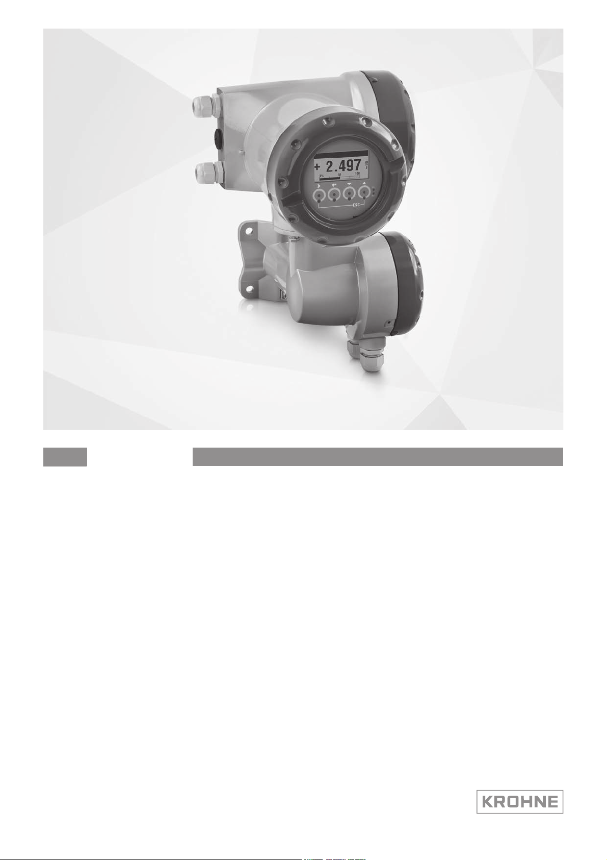
Signal converter for mass flowmeters
Electronic revision:
ER 2.1.x
The documentation is only complete when used in combination with the relevant
documentation for the flow sensor.
© KROHNE 01/2021 - 4002075808 - MA MFC400 ER2.1 R08 en
Page 2

:
IMPRINT
:::::::::::::::::::::::::::::::::::::::
All rights reserved. It is prohibited to reproduce this documentation, or any part thereof, without
the prior written authorisation of KROHNE Messtechnik GmbH.
Subject to change without notice.
Copyright 2020 by
KROHNE Messtechnik GmbH - Ludwig-Krohne-Str. 5 - 47058 Duisburg (Germany)
2
www.krohne.com 01/2021 - 4002075808 - MA MFC400 ER2.1 R08 en
Page 3

MFC 400
CONTENTS
1 Safety instructions 7
1.1 Software history ............................................................................................................... 7
1.2 Intended use ..................................................................................................................... 8
1.3 CE certification ................................................................................................................. 9
1.4 Safety instructions from the manufacturer................................................................... 10
1.4.1 Copyright and data protection .............................................................................................. 10
1.4.2 Disclaimer ............................................................................................................................. 10
1.4.3 Product liability and warranty .............................................................................................. 11
1.4.4 Information concerning the documentation......................................................................... 11
1.4.5 Warnings and symbols used................................................................................................. 12
1.5 Safety instructions for the operator............................................................................... 12
2 Device description 13
2.1 Scope of delivery............................................................................................................. 13
2.2 Device description .......................................................................................................... 14
2.2.1 Field housing......................................................................................................................... 15
2.3 Nameplates .................................................................................................................... 16
2.3.1 Example of a nameplate ....................................................................................................... 16
2.3.2 Electrical connection data of inputs/outputs (example of basic version)............................ 17
3 Installation 18
3.1 General notes on installation ......................................................................................... 18
3.2 Storage ........................................................................................................................... 18
3.3 Transport ........................................................................................................................ 18
3.4 Installation specifications .............................................................................................. 18
3.5 Mounting of the compact version................................................................................... 19
3.6 Mounting the field housing, remote version .................................................................. 19
3.6.1 Pipe mounting ....................................................................................................................... 19
3.6.2 Wall mounting....................................................................................................................... 20
3.6.3 Turning the display of the field housing version ..................................................................21
4 Electrical connections 22
4.1 Safety instructions.......................................................................................................... 22
4.2 Important notes on electrical connection...................................................................... 22
4.3 Signal cable requirements............................................................................................. 23
4.4 Connecting the signal cables ......................................................................................... 24
4.4.1 Connection of signal cable - field housing and connection box for flow sensor ................. 25
4.4.2 Connection diagram.............................................................................................................. 26
4.5 Grounding the flow sensor ............................................................................................. 26
4.6 Connecting power - all housing variants ....................................................................... 27
4.7 Inputs and outputs, overview ......................................................................................... 28
4.7.1 Combinations of the inputs/outputs (I/Os) ........................................................................... 28
4.7.2 Description of the CG number .............................................................................................. 29
4.7.3 Fixed, non-alterable input/output versions.......................................................................... 30
4.7.4 Alterable input/output versions............................................................................................ 31
www.krohne.com01/2021 - 4002075808 - MA MFC400 ER2.1 R08 en
3
Page 4

CONTENTS
MFC 400
4.8 Description of the inputs and outputs............................................................................ 32
4.8.1 Current output ...................................................................................................................... 32
4.8.2 Pulse output and frequency output ...................................................................................... 33
4.8.3 Status output and limit switch .............................................................................................. 34
4.8.4 Control input ......................................................................................................................... 35
4.9 Electrical connection of the inputs and outputs ............................................................ 36
4.9.1 Field housing, electrical connection of the inputs and outputs ........................................... 36
4.9.2 Laying electrical cables correctly......................................................................................... 37
4.10 Description of the inputs and outputs.......................................................................... 38
4.10.1 Important notes................................................................................................................... 38
4.10.2 Description of the electrical symbols................................................................................. 39
4.10.3 Modular inputs/outputs and bus systems .......................................................................... 40
4.10.4 Ex i inputs/outputs .............................................................................................................. 48
4.10.5 HART connection................................................................................................................. 51
5 Start-up 53
5.1 Switching on the power .................................................................................................. 53
5.2 Starting the signal converter ......................................................................................... 53
6 Operation 54
6.1 Display and operating elements .................................................................................... 54
6.1.1 Display in measuring mode with 2 or 3 measured values ................................................... 57
6.1.2 Display for selection of submenu and functions, 3 lines ..................................................... 57
6.1.3 Display when setting parameters, 4 lines ............................................................................ 58
6.1.4 Display when previewing parameters, 4 lines...................................................................... 58
6.2 Menu structure............................................................................................................... 59
6.3 Function tables ............................................................................................................... 63
6.3.1 Menu "Quick Setup" .............................................................................................................. 63
6.3.2 Menu "Test"........................................................................................................................... 65
6.3.3 Menu "Setup" ........................................................................................................................ 68
6.3.4 Set free units......................................................................................................................... 83
6.4 Calibration functions ......................................................................................................84
6.4.1 Zero calibration (C1.1.1 Calibrate Zero) ............................................................................... 84
6.4.2 Density calibration (C1.2.1 Calibrate Density)...................................................................... 86
6.4.3 Temperature/density tables ................................................................................................. 88
6.5 Measurement functions ................................................................................................. 91
6.5.1 Flow (C1.1.0 Flow)................................................................................................................. 91
6.5.2 Density (C1.2.0 Density) ........................................................................................................93
6.5.3 System control (C1.4.0 System Control)............................................................................... 94
6.5.4 Detection of 2 phase flow...................................................................................................... 95
6.6 I/O configuration............................................................................................................. 96
6.6.1 Damp output signals............................................................................................................. 96
6.6.2 Suppress small flow rates.................................................................................................... 96
6.6.3 Polarity of measurement ...................................................................................................... 97
6.6.4 Current output ...................................................................................................................... 97
6.6.5 Alarm signalling via current outputs.................................................................................... 98
6.6.6 Pulse output and batching applications ...............................................................................98
6.7 Display configuration......................................................................................................99
6.7.1 Optical keys (C5.3.0 Optical Keys)......................................................................................... 99
6.7.2 Backlight (C5.4.0 Backlight) ................................................................................................. 99
4
www.krohne.com 01/2021 - 4002075808 - MA MFC400 ER2.1 R08 en
Page 5

MFC 400
CONTENTS
6.8 Configuration management (C6.3.0 Config. Management) ........................................... 99
6.8.1 Load and save configuration (C6.3.1 Save Settings & C6.3.2 Load Settings) ...................... 99
6.8.2 Factory reset (C6.3.3 Factory Reset) .................................................................................. 100
6.8.3 Change log (B1.2.0 Change Log)......................................................................................... 100
6.8.4 Locking of configuration ..................................................................................................... 100
6.9 Special functions ..........................................................................................................102
6.10 SIL configuration (only for SIL capable devices)........................................................ 102
6.11 Testing of device installation (B3.0.0 Simulation)...................................................... 102
6.12 Diagnostic information and status messages ........................................................... 103
6.12.1 Status groups (C6.6.0 Status Groups)............................................................................... 104
6.12.2 Status log (B1.1.0 Status Log)........................................................................................... 105
6.12.3 Reset errors (A2.1.0 Reset Errors)................................................................................... 105
6.13 Bluetooth interface..................................................................................................... 105
7 Service 106
7.1 Replacing the signal converter electronics ................................................................. 106
7.2 Driver or sensor coil fault ............................................................................................ 107
7.2.1 OPTIMASS 1000................................................................................................................... 107
7.2.2 OPTIMASS 2000................................................................................................................... 108
7.2.3 OPTIMASS 3000................................................................................................................... 109
7.2.4 OPTIMASS 6000................................................................................................................... 110
7.2.5 OPTIMASS 7000................................................................................................................... 111
7.3 Spare parts availability................................................................................................. 112
7.4 Availability of services .................................................................................................. 112
7.5 Returning the device to the manufacturer................................................................... 112
7.5.1 General information............................................................................................................ 112
7.5.2 Form (for copying) to accompany a returned device.......................................................... 113
7.6 Disposal ........................................................................................................................ 113
7.7 Disassembly and recycling........................................................................................... 114
7.7.1 Disassembly of aluminum or stainless steel field housing ............................................... 115
7.7.2 Disassembly of aluminum or stainless steel compact housing ........................................ 116
7.7.3 Location of battery .............................................................................................................. 117
7.7.4 Overview of the materials and components....................................................................... 117
8 Technical data 119
8.1 Measuring principle...................................................................................................... 119
8.2 Technical data............................................................................................................... 119
8.3 Dimensions and weight ................................................................................................ 131
8.3.1 Housing ............................................................................................................................... 131
8.3.2 Mounting plate of field housing .......................................................................................... 132
www.krohne.com01/2021 - 4002075808 - MA MFC400 ER2.1 R08 en
5
Page 6

CONTENTS
MFC 400
9 Description of HART interface 133
9.1 General description ...................................................................................................... 133
9.2 Software history ...........................................................................................................133
9.3 Connection variants...................................................................................................... 134
9.3.1 Point-to-Point connection - analogue / digital mode......................................................... 135
9.3.2 Multi-Drop connection (2-wire connection) ....................................................................... 136
9.3.3 Multi-Drop connection (3-wire connection) ....................................................................... 137
9.4 Inputs/outputs and HART dynamic variables and device variables ............................ 138
10 Description of Bluetooth interface 140
10.1 Introduction ................................................................................................................ 140
10.1.1 Functionality...................................................................................................................... 140
10.1.2 Quick start guide ............................................................................................................... 140
10.2 Security considerations.............................................................................................. 141
10.2.1 Wireless security concept................................................................................................. 141
10.2.2 Bluetooth interface and SIL mode .................................................................................... 141
10.3 Field device setup....................................................................................................... 142
10.3.1 Bluetooth access level ...................................................................................................... 142
10.3.2 Bluetooth access level setting via mechanical switch ..................................................... 143
10.3.3 Bluetooth access level setting via software (C8.1.0 Access Level).................................. 144
10.3.4 Password for the Bluetooth interface (C8.2.0 Password) ................................................ 144
10.3.5 LED Signalling (C8.3.0) ..................................................................................................... 145
10.3.6 Reset Bluetooth lockout (A2.7.0, C8.4.0) .......................................................................... 145
10.3.7 Check Bluetooth connection status (B1.7.1) .................................................................... 146
10.3.8 Login history (B1.7.2, B1.7.3) ............................................................................................ 146
10.4 Installation of the OPTICHECK Flow Mobile app ....................................................... 146
10.5 FCC and ISED statements .......................................................................................... 147
11 Notes 149
6
www.krohne.com 01/2021 - 4002075808 - MA MFC400 ER2.1 R08 en
Page 7

MFC 400
SAFETY INSTRUCTIONS
1.1 Software history
The "Electronic Revision" (ER) is consulted to document the revision status of electronic
equipment according to NE 53 for all devices. It is easy to see from the ER whether
troubleshooting or larger changes in the electronic equipment have taken place and how that
has affected the compatibility.
1 Downwards compatible changes and fault repair with no effect on operation
(e.g. spelling mistakes on display)
2-_ Downwards compatible hardware and/or software change of interfaces:
H
P Profibus
F Foundation Fieldbus
M Modbus
N PROFINET IO
BT
X all interfaces
3-_ Downwards compatible hardware and/or software change of inputs and outputs:
I Current output
F, P Frequency / pulse output
S Status output
C Control input
LS Limit switch
X all inputs and outputs
4 Downwards compatible changes with new functions.
5 Incompatible changes, i.e. electronic equipment must be changed.
Table 1-1: Description of changes
®
HART
Bluetooth
®
1
INFORMATION!
In the table below, "_" is a placeholder for possible multi-digit alphanumeric combinations,
depending on the available version.
www.krohne.com01/2021 - 4002075808 - MA MFC400 ER2.1 R08 en
7
Page 8
1
SAFETY INSTRUCTIONS
MFC 400
Release date Electronic revision (ER) Changes and compatibility Documentation
09/2012 ER 1.0.0_ - MA MFC400 R01
03/2013 ER 1.0.1_ 1 MA MFC400 R02
06/2013 ER 1.0.2_ 1; 2-M; 2-H MA MFC400 R02
ER 1.0.3_ 1; 2-F; 2-P; 2-X MA MFC400 R02
11/2013 ER 1.0.4_ 2-H; 3-P; 3-F MA MFC400 R03
05/2014 ER 1.0.5_ 1 MA MFC400 R03
08/2014 ER 1.0.6_ 1; 3-P; 3-I; 2-H MA MFC400 R03
08/2017 ER 1.0.7_ 1; 2-F; 3-F MA MFC400 R03
07/2016 ER 2.0.0_ 5 1 MA MFC400 ER2.0 R04
07/2017 ER 2.0.1_ 1 MA MFC400 ER2.0 R05
08/2017 ER 2.0.2_ 1; 2-P; 2-F; 2-N MA MFC400 ER2.0 R05
11/2018 ER 2.0.3_ 1 MA MFC400 ER2.0 R05
08/2019 ER 2.0.4_ 1; 2-M MA MFC400 ER2.0 R06
01/2020 ER 2.1.0_ 1; 2-BT 2 MA MFC400 ER2.1 R07, R08
Table 1-2: Software changes and effect on compatibility
1 Incompatible change: hardware and software change; SIL mode capability
2 Incompatible change: hardware and software change; Bluetooth
®
functionality added
1.2 Intended use
The mass flowmeters are designed exclusively to directly measure mass flow rates, product
density and temperature as well to indirectly measure parameters such as the total volume and
concentration of dissolved substances as well as the volume flow rate.
DANGER!
For devices used in hazardous areas, additional safety notes apply; please refer to the Ex
documentation.
CAUTION!
For devices used in SIL applications, additional safety notes apply. For detailed information refer
to the "Safety manual".
WARNING!
If the device is not used according to the operating conditions (refer to chapter "Technical data"),
the intended protection could be affected.
INFORMATION!
This device is a Group 1, Class A device as specified within CISPR11:2009. It is intended for use in
industrial environment. There may be potential difficulties in ensuring electromagnetic
compatibility in other environments, due to conducted as well as radiated disturbances.
8
www.krohne.com 01/2021 - 4002075808 - MA MFC400 ER2.1 R08 en
Page 9

MFC 400
1.3 CE certification
CE marking
This device conforms with the most recent and up to date versions of the following:
• EMC Directive
• ATEX Directive
• Low Voltage Directive
• Pressure Equipment Directive (PED)
• RoHS
• Measuring Instrument Directive
• Radio Equipment Directive (RED)
SAFETY INSTRUCTIONS
1
The manufacturer declares conformity and the device carries the CE mark.
www.krohne.com01/2021 - 4002075808 - MA MFC400 ER2.1 R08 en
9
Page 10

1
SAFETY INSTRUCTIONS
1.4 Safety instructions from the manufacturer
1.4.1 Copyright and data protection
The contents of this document have been created with great care. Nevertheless, we provide no
guarantee that the contents are correct, complete or up-to-date.
The contents and works in this document are subject to copyright. Contributions from third
parties are identified as such. Reproduction, processing, dissemination and any type of use
beyond what is permitted under copyright requires written authorisation from the respective
author and/or the manufacturer.
The manufacturer tries always to observe the copyrights of others, and to draw on works created
in-house or works in the public domain.
The collection of personal data (such as names, street addresses or e-mail addresses) in the
manufacturer's documents is always on a voluntary basis whenever possible. Whenever
feasible, it is always possible to make use of the offerings and services without providing any
personal data.
MFC 400
We draw your attention to the fact that data transmission over the Internet (e.g. when
communicating by e-mail) may involve gaps in security. It is not possible to protect such data
completely against access by third parties.
We hereby expressly prohibit the use of the contact data published as part of our duty to publish
an imprint for the purpose of sending us any advertising or informational materials that we have
not expressly requested.
1.4.2 Disclaimer
The manufacturer will not be liable for any damage of any kind by using its product, including,
but not limited to direct, indirect or incidental and consequential damages.
This disclaimer does not apply in case the manufacturer has acted on purpose or with gross
negligence. In the event any applicable law does not allow such limitations on implied warranties
or the exclusion of limitation of certain damages, you may, if such law applies to you, not be
subject to some or all of the above disclaimer, exclusions or limitations.
Any product purchased from the manufacturer is warranted in accordance with the relevant
product documentation and our Terms and Conditions of Sale.
The manufacturer reserves the right to alter the content of its documents, including this
disclaimer in any way, at any time, for any reason, without prior notification, and will not be liable
in any way for possible consequences of such changes.
10
www.krohne.com 01/2021 - 4002075808 - MA MFC400 ER2.1 R08 en
Page 11

MFC 400
1.4.3 Product liability and warranty
The operator shall bear responsibility for the suitability of the device for the specific purpose.
The manufacturer accepts no liability for the consequences of misuse by the operator. Improper
installation or operation of the devices (systems) will cause the warranty to be void. The
respective "Standard Terms and Conditions" which form the basis for the sales contract shall
also apply.
1.4.4 Information concerning the documentation
To prevent any injury to the user or damage to the device it is essential that you read the
information in this document and observe applicable national standards, safety requirements
and accident prevention regulations.
If this document is not in your native language and if you have any problems understanding the
text, we advise you to contact your local office for assistance. The manufacturer can not accept
responsibility for any damage or injury caused by misunderstanding of the information in this
document.
This document is provided to help you establish operating conditions, which will permit safe and
efficient use of this device. Special considerations and precautions are also described in the
document, which appear in the form of icons as shown below.
SAFETY INSTRUCTIONS
1
www.krohne.com01/2021 - 4002075808 - MA MFC400 ER2.1 R08 en
11
Page 12
1
SAFETY INSTRUCTIONS
1.4.5 Warnings and symbols used
Safety warnings are indicated by the following symbols.
DANGER!
This warning refers to the immediate danger when working with electricity.
DANGER!
This warning refers to the immediate danger of burns caused by heat or hot surfaces.
DANGER!
This warning refers to the immediate danger when using this device in a hazardous atmosphere.
DANGER!
These warnings must be observed without fail. Even partial disregard of this warning can lead to
serious health problems and even death. There is also the risk of seriously damaging the device
or parts of the operator's plant.
MFC 400
WARNING!
Disregarding this safety warning, even if only in part, poses the risk of serious health problems.
There is also the risk of damaging the device or parts of the operator's plant.
CAUTION!
Disregarding these instructions can result in damage to the device or to parts of the operator's
plant.
INFORMATION!
These instructions contain important information for the handling of the device.
LEGAL NOTICE!
This note contains information on statutory directives and standards.
• HANDLING
HANDLING
HANDLINGHANDLING
This symbol designates all instructions for actions to be carried out by the operator in the
specified sequence.
i RESULT
RESULT
RESULTRESULT
This symbol refers to all important consequences of the previous actions.
1.5 Safety instructions for the operator
12
WARNING!
In general, devices from the manufacturer may only be installed, commissioned, operated and
maintained by properly trained and authorized personnel.
This document is provided to help you establish operating conditions, which will permit safe and
efficient use of this device.
www.krohne.com 01/2021 - 4002075808 - MA MFC400 ER2.1 R08 en
Page 13
MFC 400
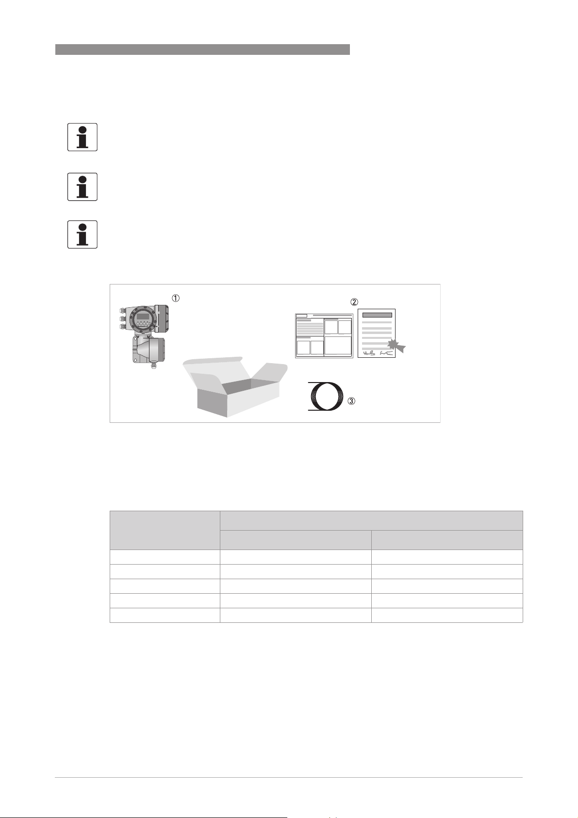
2.1 Scope of delivery
INFORMATION!
Inspect the packaging carefully for damages or signs of rough handling. Report damage to the
carrier and to the local office of the manufacturer.
INFORMATION!
Do a check of the packing list to make sure that you have all the elements given in the order.
INFORMATION!
Look at the device nameplate to ensure that the device is delivered according to your order.
Check for the correct supply voltage printed on the nameplate.
DEVICE DESCRIPTION
2
Figure 2-1: Scope of delivery
1 Device in the version as ordered
2 Product documentation
3 Signal cable (only for remote version)
Flow sensor Flow sensor + signal converter MFC 400
Compact version Remote field housing
OPTIMASS 1000 OPTIMASS 1400 C OPTIMASS 1400 F
OPTIMASS 2000 OPTIMASS 2400 C OPTIMASS 2400 F
OPTIMASS 3000 OPTIMASS 3400 C OPTIMASS 3400 F
OPTIMASS 6000 OPTIMASS 6400 C OPTIMASS 6400 F
OPTIMASS 7000 OPTIMASS 7400 C OPTIMASS 7400 F
Table 2-1: Signal converter / flow sensor combination possibilities
www.krohne.com01/2021 - 4002075808 - MA MFC400 ER2.1 R08 en
13
Page 14
2
DEVICE DESCRIPTION
2.2 Device description
The mass flowmeters are designed exclusively to directly measure mass flow rates, product
density and temperature as well to indirectly measure parameters such as the total volume,
concentration of dissolved substances and the volume flow rate.
Your measuring device is supplied ready for operation. The factory settings for the operating
data have been made in accordance with your order specifications.
The following versions are available:
• Compact version (the signal converter is mounted directly on the flow sensor)
• Remote version (electrical connection to the flow sensor via field current and signal cable)
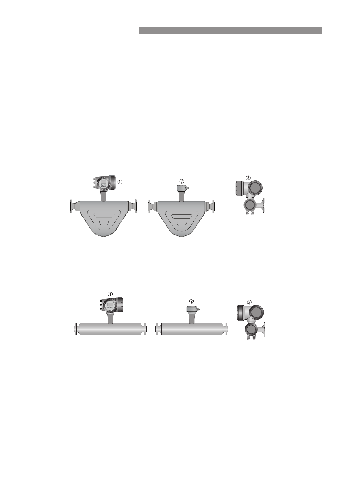
MFC 400
Figure 2-2: Versions with bent tube
1 Compact version
2 Flow sensor with connection box
3 Field housing
Figure 2-3: Versions with straight tube
1 Compact version
2 Flow sensor with connection box
3 Field housing
14
www.krohne.com 01/2021 - 4002075808 - MA MFC400 ER2.1 R08 en
Page 15
MFC 400
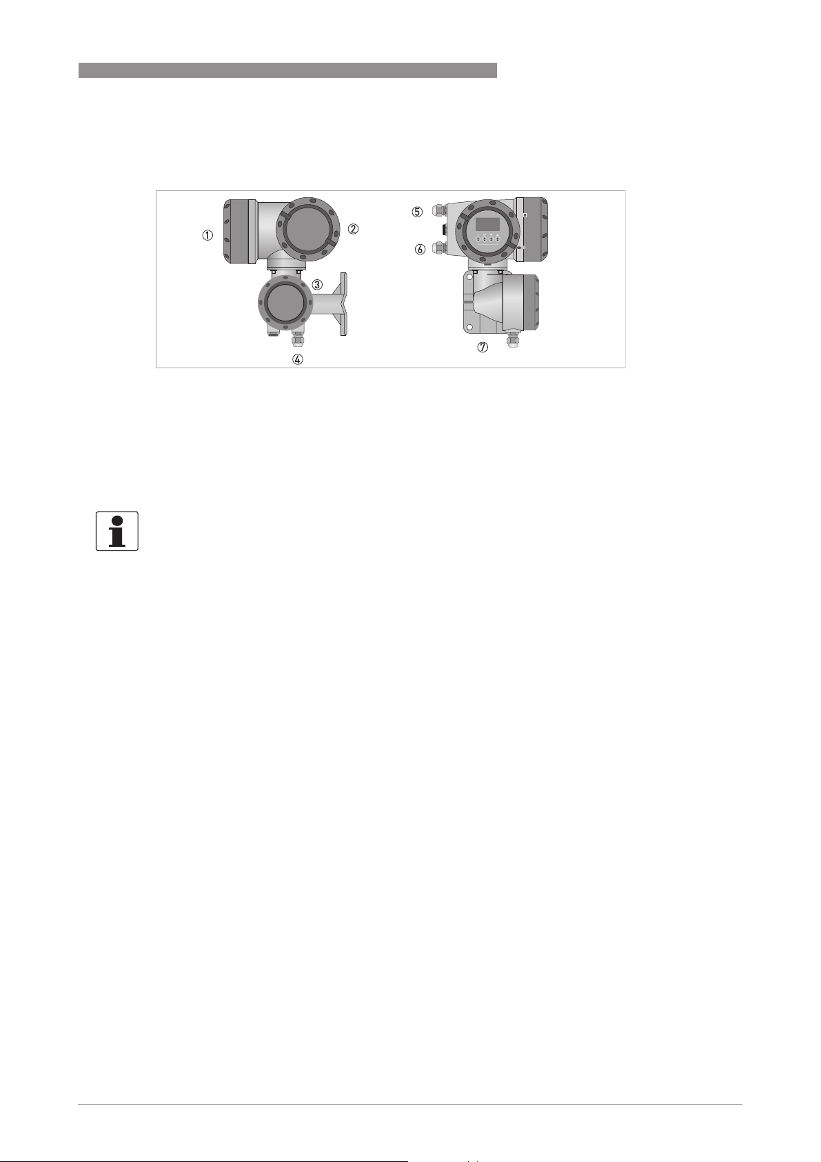
2.2.1 Field housing
Figure 2-4: Construction of the field housing
1 Cover for electronics and display
2 Cover for power supply and inputs/outputs terminal compartment
3 Cover for flow sensor terminal compartment
4 Cable entry for flow sensor signal cable
5 Cable entry for power supply
6 Cable entry for inputs and outputs
7 Mounting plate for pipe and wall mounting
DEVICE DESCRIPTION
2
INFORMATION!
Each time a housing cover is opened, the thread should be cleaned and greased. Use only resinfree and acid-free grease.
Ensure that the housing gasket is properly fitted, clean and undamaged.
www.krohne.com01/2021 - 4002075808 - MA MFC400 ER2.1 R08 en
15
Page 16
2
DEVICE DESCRIPTION
2.3 Nameplates
INFORMATION!
Look at the device nameplate to ensure that the device is delivered according to your order.
Check for the correct supply voltage printed on the nameplate.
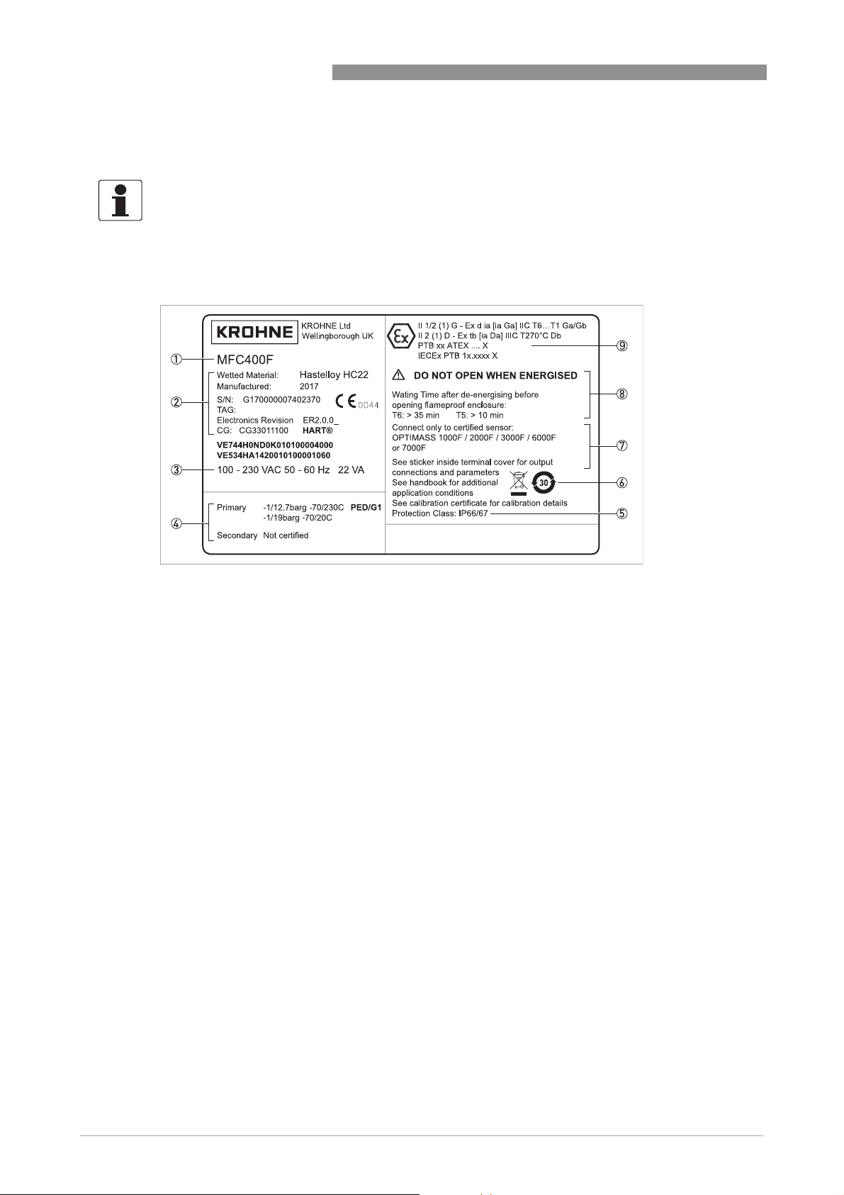
2.3.1 Example of a nameplate
MFC 400
Figure 2-5: Example of a nameplate
1 Product designation
2 Data about wetted material, manufacturing date, serial number, electronic revision and CG number
3 Electrical connection data
4 PED data
5 Protection category
6 Marking for WEEE disposal and China RoHS
7 Reference to additional information: flow sensor combination, sticker in terminal cover for output connections,
documentation, calibration certificates, etc.
8 Approvals-related thresholds
9 Approvals-related information: Ex approval, type test certificate, hygienic approvals, etc.
16
www.krohne.com 01/2021 - 4002075808 - MA MFC400 ER2.1 R08 en
Page 17
MFC 400
DEVICE DESCRIPTION
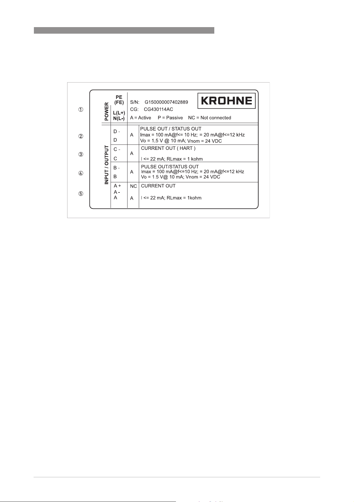
2.3.2 Electrical connection data of inputs/outputs (example of basic version)
2
Figure 2-6: Example of a nameplate for electrical connection data of inputs and outputs
1 Power supply (AC: L and N; DC: L+ and L-; PE for ≥ 24 VAC; FE for ≤ 24 VAC and DC)
2 Connection data of connection terminal D/D-
3 Connection data of connection terminal C/C-
4 Connection data of connection terminal B/B-
5 Connection data of connection terminal A/A-; A+ only operable in the basic version
• A = active mode; the signal converter supplies the power for connection of the subsequent
devices
• P = passive mode; external power supply required for operation of the subsequent devices
• N/C = connection terminals not connected
www.krohne.com01/2021 - 4002075808 - MA MFC400 ER2.1 R08 en
17
Page 18

3
INSTALLATION
3.1 General notes on installation
INFORMATION!
Inspect the packaging carefully for damages or signs of rough handling. Report damage to the
carrier and to the local office of the manufacturer.
INFORMATION!
Do a check of the packing list to make sure that you have all the elements given in the order.
INFORMATION!
Look at the device nameplate to ensure that the device is delivered according to your order.
Check for the correct supply voltage printed on the nameplate.
3.2 Storage
• Store the device in a dry, dust-free location.
• Avoid continuous direct sunlight.
• Store the device in its original packing.
• Storage temperature: -40...+70°C / -40...+158°F
MFC 400
3.3 Transport
Signal converter
• No special requirements.
Compact version
• Do not lift the device by the signal converter housing.
• Do not use lifting chains.
• To transport flange devices, use lifting straps. Wrap these around both process connections.
3.4 Installation specifications
INFORMATION!
The following precautions must be taken to ensure reliable installation.
•
Make sure that there is adequate space to the sides.
•
The device must not be heated by radiated heat (e.g. exposure to the sun) to an electronics
housing surface temperature above the maximum permissible ambient temperature. If it is
necessary to prevent damage from heat sources, a heat protection (e.g. sun shade) has to be
installed.
•
Signal converters installed in control cabinets require adequate cooling, e.g. by fan or heat
exchanger.
•
Do not expose the signal converter to intense vibrations. The measuring devices are tested
for a vibration level as described in the chapter "Technical data".
18
www.krohne.com 01/2021 - 4002075808 - MA MFC400 ER2.1 R08 en
Page 19
MFC 400
3.5 Mounting of the compact version
CAUTION!
Turning the housing of the compact version is not permitted.
INFORMATION!
The signal converter is mounted directly on the flow sensor. For installation of the flowmeter,
please observe the instructions in the supplied product documentation for the flow sensor.
3.6 Mounting the field housing, remote version
CAUTION!
Remarks for sanitary applications
•
To prevent contamination and dirt deposits behind the mounting plate, a cover plug must be
installed between the wall and the mounting plate.
•
Pipe mounting is not suitable for sanitary applications!
INFORMATION!
Assembly materials and tools are not part of the delivery. Use the assembly materials and tools
in compliance with the applicable occupational health and safety directives.
INSTALLATION
3
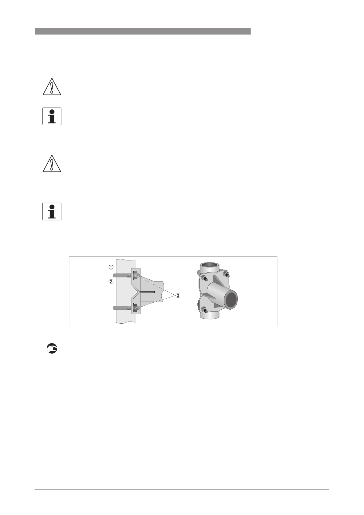
3.6.1 Pipe mounting
Figure 3-1: Pipe mounting of the field housing
1 Fix the mounting bracket of the signal converter to the pipe.
2 Fasten the mounting bracket of the signal converter using standard U-bolts and washers.
3 Tighten the nuts.
www.krohne.com01/2021 - 4002075808 - MA MFC400 ER2.1 R08 en
19
Page 20
3
INSTALLATION
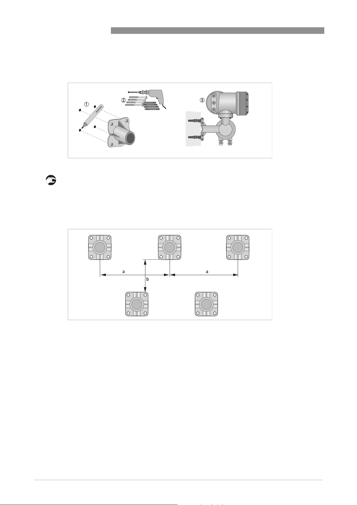
3.6.2 Wall mounting
Figure 3-2: Wall mounting of the field housing
MFC 400
1 Prepare the holes with the aid of the mounting plate. For further information refer to
plate of field housing
on page 132.
Mounting
2 Fasten the mounting plate securely to the wall.
3 Screw the mounting bracket of the signal converter to the mounting plate with the nuts and
washers.
Figure 3-3: Mounting multiple devices next to each other
a ≥ 600 mm / 23.6"
b ≥ 250 mm / 9.8"
20
www.krohne.com 01/2021 - 4002075808 - MA MFC400 ER2.1 R08 en
Page 21
MFC 400
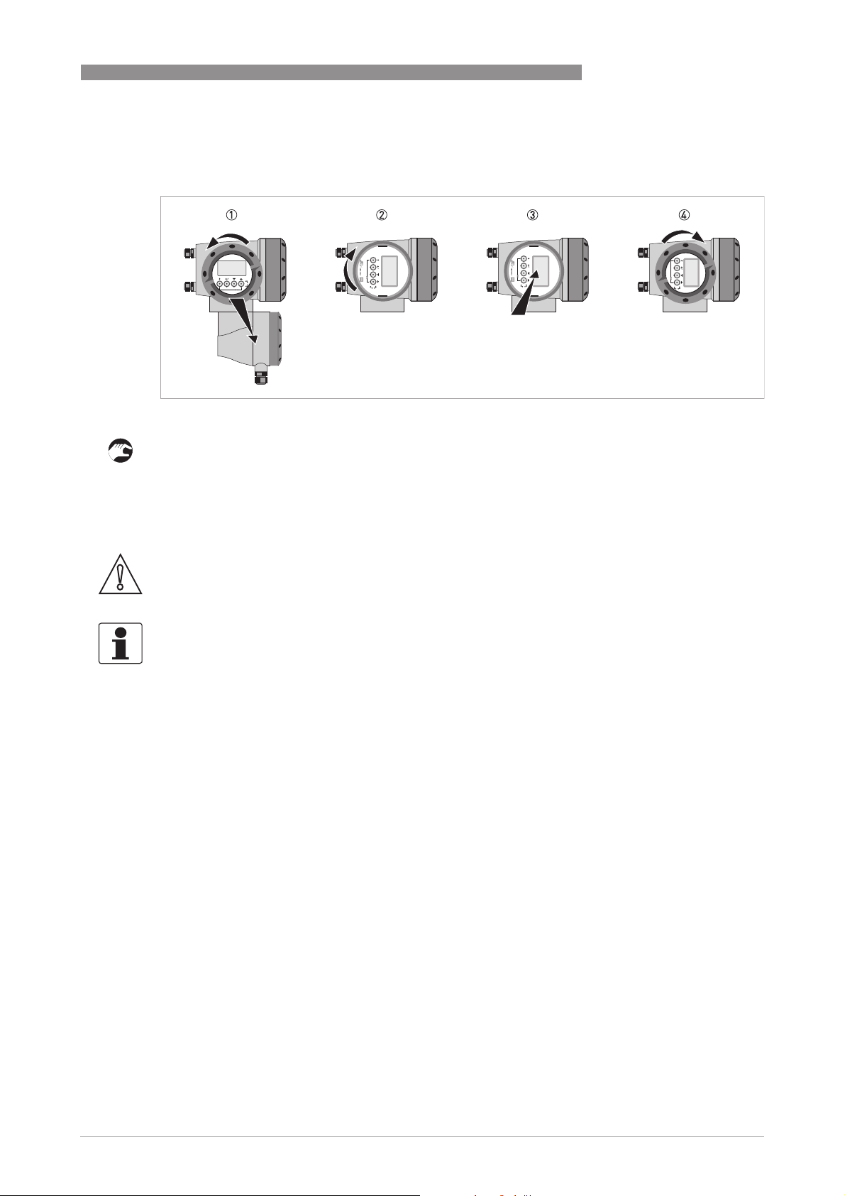
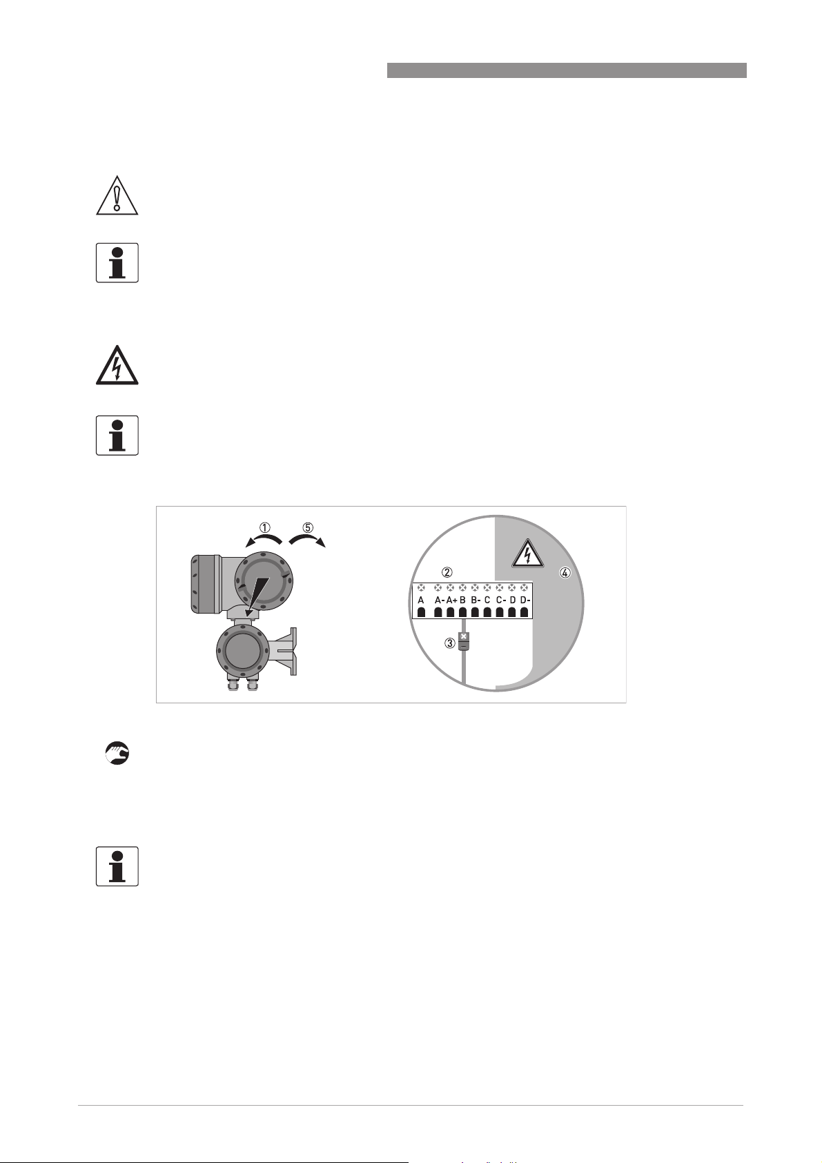
3.6.3 Turning the display of the field housing version
Figure 3-4: Turning the display of the field housing version
The display of the field housing version can be turned in 90° increments
1 Unscrew the cover from the display and operation control unit.
2 Pull out the display and rotate it to the required position.
3 Slide the display back into the housing.
4 Re-fit the cover and tighten it by hand.
INSTALLATION
3
CAUTION!
The ribbon cable of the display must not be folded or twisted repeatedly.
INFORMATION!
Each time a housing cover is opened, the thread should be cleaned and greased. Use only resinfree and acid-free grease.
Ensure that the housing gasket is properly fitted, clean and undamaged.
www.krohne.com01/2021 - 4002075808 - MA MFC400 ER2.1 R08 en
21
Page 22
4
ELECTRICAL CONNECTIONS
4.1 Safety instructions
DANGER!
All work on the electrical connections may only be carried out with the power disconnected.
Take note of the voltage data on the nameplate!
DANGER!
Observe the national regulations for electrical installations!
DANGER!
For devices used in hazardous areas, additional safety notes apply; please refer to the Ex
documentation.
WARNING!
Observe without fail the local occupational health and safety regulations.
Any work done on the electrical components of the measuring device may only be carried out by
properly trained specialists.
MFC 400
INFORMATION!
Look at the device nameplate to ensure that the device is delivered according to your order.
Check for the correct supply voltage printed on the nameplate.
4.2 Important notes on electrical connection
DANGER!
Electrical connection is carried out in conformity with the VDE 0100 directive "Regulations for
electrical power installations with line voltages up to 1000 V" or equivalent national regulations.
DANGER!
The device must be grounded in accordance with regulations in order to protect personnel
against electric shocks.
CAUTION!
•
Use suitable cable entries for the various electrical cables.
•
The flow sensor and signal converter have been configured together at the factory. For this
reason, please connect the devices in pairs.
22
www.krohne.com 01/2021 - 4002075808 - MA MFC400 ER2.1 R08 en
Page 23

MFC 400
4.3 Signal cable requirements
CAUTION!
It is strongly recommended that the signal cable for remote flowmeters is provided by the
manufacturer.
Specifications for standard signal cables
• 5 twisted pair circuits (24 AWG)
• Insulation thickness of cables: ≥ 0.2 mm / 0.008"
• Each cable pair shielded with foil and drain wire
• Overall foil/braid shield
• Casing colour: grey
• Colour of wires:
Pair 1: yellow/black
Pair 2: green/black
Pair 3: blue/black
Pair 4: red/black
Pair 5: white/black
• Test voltage: ≥ 100 VAC
• Temperature range: -40...+85°C / -40...+185°F
• Capacity between cables: ≤ 41 pF/m
• Capacity compared to shielding: ≤ 73 pF/m
• Inductance: ≤ 0.8 µH/m
ELECTRICAL CONNECTIONS
4
Specifications for cables in hazardous areas
• 5 twisted pair circuits (24 AWG)
• Insulation thickness of cables: ≥ 0.2 mm / 0.008"
• Each cable pair shielded with foil and drain wire
• Overall foil/braid shield
• Casing colour: blue
• Colour of wires:
Pair 1: yellow/black
Pair 2: green/black
Pair 3: blue/black
Pair 4: red/black
Pair 5: white/black
• Test voltage: ≥ 100 VAC
• Temperature range: -40...+85°C / -40...+185°F
• Capacity between cables: ≤ 41 pF/m
• Capacity compared to shielding: ≤ 73 pF/m
• Inductance: ≤ 0.8 µH/m
www.krohne.com01/2021 - 4002075808 - MA MFC400 ER2.1 R08 en
23
Page 24
4
ELECTRICAL CONNECTIONS
4.4 Connecting the signal cables
DANGER!
Cables may only be connected when the power is switched off.
DANGER!
The device must be grounded in accordance with regulations in order to protect personnel
against electric shocks.
DANGER!
For devices used in hazardous areas, additional safety notes apply; please refer to the Ex
documentation.
WARNING!
Observe without fail the local occupational health and safety regulations.
Any work done on the electrical components of the measuring device may only be carried out by
properly trained specialists.
MFC 400
24
www.krohne.com 01/2021 - 4002075808 - MA MFC400 ER2.1 R08 en
Page 25
MFC 400
ELECTRICAL CONNECTIONS
4.4.1 Connection of signal cable - field housing and connection box for flow sensor
Figure 4-1: Connection of signal cable - field housing and connection box for flow sensor
1 Unscrew the terminal compartment cover.
2 Pass the prepared signal cable through the cable entry.
3 Secure the signal cable using the clip.
4 Connect the electrical conductors as shown. The shielding must also be connected to the
spring terminal.
5 Re-fit the cover and tighten it by hand.
4
Cable Connection terminal
Cable pair Colour
1 yellow X1 SA+
1 black X1 SA-
2 green X1 SB+
2 black X1 SB-
3 blue X2 T1
3 black X2 T2
4 red X2 T3
4 black X2 T4
5 white X3 DR+
5 black X3 DR-
Table 4-1: Colour coding of cables
INFORMATION!
Each time a housing cover is opened, the thread should be cleaned and greased. Use only resinfree and acid-free grease.
Ensure that the housing gasket is properly fitted, clean and undamaged.
www.krohne.com01/2021 - 4002075808 - MA MFC400 ER2.1 R08 en
25
Page 26
4
ELECTRICAL CONNECTIONS
4.4.2 Connection diagram
DANGER!
The device must be grounded in accordance with regulations in order to protect personnel
against electric shocks.
MFC 400
Figure 4-2: Connection diagram
1 Terminal compartment for signal converter
2 Terminal compartment for flow sensor
3 Connect shielding to spring terminal (drain wire and overall shield)
4.5 Grounding the flow sensor
DANGER!
There should be no difference in potential between the flow sensor and the housing or protective
earth of the signal converter!
• The flow sensor must be properly grounded.
• The grounding cable should not transmit any interference voltages.
• Do not use the grounding cable to connect more than one device to ground.
• The flow sensors are connected to ground by means of a functional grounding conductor FE.
• In hazardous areas, grounding is used at the same time for equipotential bonding. Additional
grounding instructions are provided in the supplementary "Ex documentation", which are
only supplied together with hazardous area equipment.
26
www.krohne.com 01/2021 - 4002075808 - MA MFC400 ER2.1 R08 en
Page 27
MFC 400
ELECTRICAL CONNECTIONS
4.6 Connecting power - all housing variants
DANGER!
The device must be grounded in accordance with regulations in order to protect personnel
against electric shocks.
DANGER!
For devices used in hazardous areas, additional safety notes apply; please refer to the Ex
documentation.
• The protection category depends on the housing versions (IP66/67 or NEMA4/4X).
• The housings of the devices, which are designed to protect the electronic equipment from
dust and moisture, should be kept well closed at all times. Creepage distances and
clearances are dimensioned to VDE 0110 and IEC 60664 for pollution severity 2. Supply
circuits are designed for overvoltage category III and the output circuits for overvoltage
category II.
• Fuse protection (I
breaker) to isolate the signal converter must be provided close to the device. The separator
must be marked as the separator for this device.
≤ 16 A) for the infeed power circuit, as well as a separator (switch, circuit
N
4
100...230 VAC (tolerance range: -15% / +10%)
• Note the power supply voltage and frequency (50...60 Hz) on the nameplate.
• The protective ground terminal PE
clamp terminal in the terminal compartment of the signal converter.
PE of the power supply must be connected to the separate U-
PEPE
INFORMATION!
240 VAC + 5% is included in the tolerance range.
24 VDC (tolerance range: -55% / +30%)
• Note the data on the nameplate!
• For measurement process reasons, a functional ground FE
separate U-clamp terminal in the terminal compartment of the signal converter.
• When connecting to functional extra-low voltages, provide a facility for protective separation
(PELV) (according to VDE 0100 / VDE 0106 and/or IEC 60364 / IEC 61140 or relevant national
regulations).
FE must be connected to the
FEFE
INFORMATION!
For 24 VDC, 12 VDC - 10% is included in the tolerance range.
www.krohne.com01/2021 - 4002075808 - MA MFC400 ER2.1 R08 en
27
Page 28

4
ELECTRICAL CONNECTIONS
Figure 4-3: Power supply connection
1 100...230 VAC (-15% / +10%), 22 VA
2 24 VDC (-55% / +30%), 12 W
4.7 Inputs and outputs, overview
4.7.1 Combinations of the inputs/outputs (I/Os)
This signal converter is available with various input/output combinations.
Modular version
• Depending on the task, the device can be configured with various output modules.
MFC 400
Ex i version
• Depending on the task, the device can be configured with various output modules.
• Current outputs can be active or passive.
• Optionally available also with Foundation Fieldbus and Profibus PA.
Bus systems
• The device allows intrinsically safe and non intrinsically safe bus interfaces in combination
with additional modules.
• For connection and operation of bus systems, note the supplementary instructions.
Ex option
• For hazardous areas, all of the input/output variants for the housing designs C and F can be
delivered with terminal compartment in Ex d (pressure-resistant casing) or Ex e (increased
safety).
• For connection and operation of Ex devices, note the supplementary instructions.
28
www.krohne.com 01/2021 - 4002075808 - MA MFC400 ER2.1 R08 en
Page 29
MFC 400
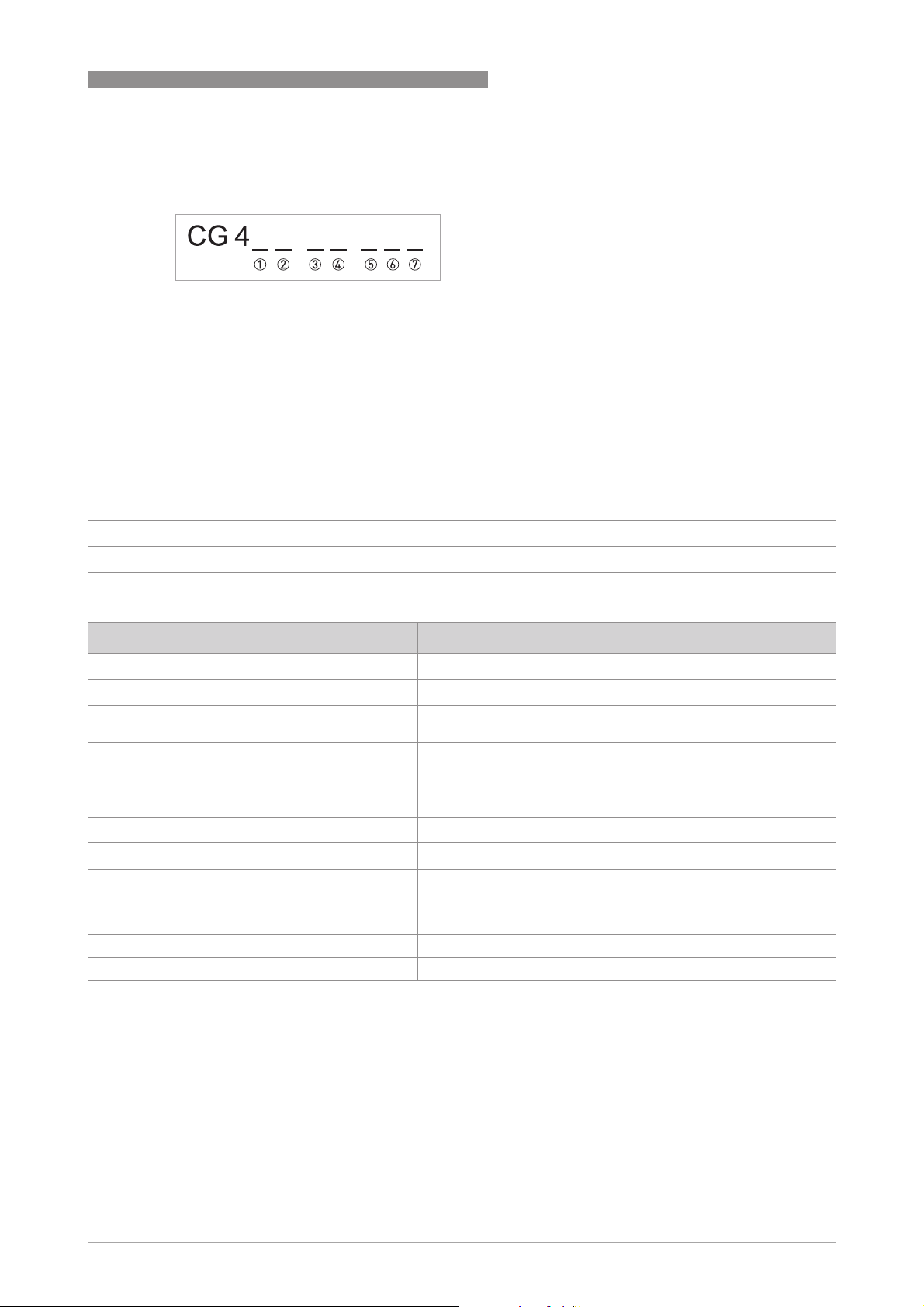
4.7.2 Description of the CG number
Figure 4-4: Marking (CG number) of the electronics module and input/output variants
1 ID number: 3
2 ID number: 0 = standard
3 Power supply option
4 Display
5 Input/output version (I/O)
6 1st optional module for connection terminal A
7 2nd optional module for connection terminal B
The last 3 digits of the CG number (5, 6 and 7) indicate the assignment of the terminal
connections.
Please refer to the following examples.
ELECTRICAL CONNECTIONS
4
CG430114AC 100...230 VAC & standard display; modular I/O: Ia & PN/SN and optional module Ia/SN & Pa/S
CG43081200 24 VDC & standard display; Ex i I/O: Ia & Pa/Sa and optional module Ia & PN/SN/C
Table 4-2: Examples for CG number
N
Abbreviation Identifier for CG number Description
I
a
I
p
Pa / S
a
Pp / S
p
PN / S
N
C
a
C
p
C
N
- 8 No additional module installed
- 0 No further module possible
Table 4-3: Description of abbreviations and CG identifier for possible optional modules on terminals A and B
A Active current output
B Passive current output
C Active pulse output, frequency output, status output or limit
switch (changeable)
E Passive pulse output, frequency output, status output or limit
switch (changeable)
F Passive pulse output, frequency output, status output or limit
switch according to NAMUR (changeable)
G Active control input
K Passive control input
H Active control input according to NAMUR
Signal converter monitors cable breaks and short circuits
according to EN 60947-5-6. Errors indicated on LC display.
Error messages possible via status output.
a
www.krohne.com01/2021 - 4002075808 - MA MFC400 ER2.1 R08 en
29
Page 30

4
ELECTRICAL CONNECTIONS
4.7.3 Fixed, non-alterable input/output versions
This signal converter is available with various input/output combinations.
• The grey boxes in the tables denote unassigned or unused connection terminals.
• In the table, only the final digits of the CG no. are depicted.
CG no. Connection terminals
A+ A A- B B- C C- D D-
Ex i I/Os (option)
2 0 0
3 0 0
2 1 0 Ia active PN / SNNAMUR
Cp passive 1
3 1 0 Ia active PN / SNNAMUR
passive 1
C
p
2 2 0 Ip passive PN / SNNAMUR
Cp passive 1
3 2 0 Ip passive PN / SNNAMUR
passive 1
C
p
Ia + HART® active
Ip + HART® passive
Ia + HART® active
Ip + HART® passive
Ia + HART® active
Ip + HART® passive
MFC 400
PN / SN NAMUR 1
PN / SN NAMUR 1
PN / SN NAMUR 1
PN / SN NAMUR 1
PN / SNNAMUR 1
PN / SNNAMUR 1
PROFIBUS PA (Ex i) (option)
D 0 0 PA+ PA- PA+ PA-
FISCO Device FISCO Device
D 1 0 Ia active PN / SNNAMUR
passive 1
C
p
D 2 0 Ip passive PN / SNNAMUR
passive 1
C
p
PA+ PA- PA+ PA-
FISCO Device FISCO Device
PA+ PA- PA+ PA-
FISCO Device FISCO Device
FOUNDATION Fieldbus (Ex i) (option)
E 0 0 V/D+ V/D- V/D+ V/D-
FISCO Device FISCO Device
E 1 0 Ia active PN / SNNAMUR
passive 1
C
p
E 2 0 Ip passive PN / SNNAMUR
Cp passive 1
V/D+ V/D- V/D+ V/D-
FISCO Device FISCO Device
V/D+ V/D- V/D+ V/D-
FISCO Device FISCO Device
PROFINET IO (option)
N 0 0 RX+ RX- TX+ TX- TX+ TX- RX+ RX-
Port 2 Port 1
Table 4-4: Electrical connection of fixed, non-alterable input/output versions
1 Changeable
30
www.krohne.com 01/2021 - 4002075808 - MA MFC400 ER2.1 R08 en
Page 31

MFC 400
ELECTRICAL CONNECTIONS
4.7.4 Alterable input/output versions
This signal converter is available with various input/output combinations.
• The grey boxes in the tables denote unassigned or unused connection terminals.
• In the table, only the final digits of the CG no. are depicted.
• Term. = (connection) terminal
CG no. Connection terminals
A+ A A- B B- C C- D D-
Modular I/Os (option)
4 _ _ max. 2 optional modules for term. A + B
I + HART®
active/passive 1
PROFIBUS PA (option)
D _ _ max. 2 optional modules for term. A + B PA+ (2) PA- (2) PA+ (1) PA- (1)
P/S active/passive/
NAMUR 1
4
FOUNDATION Fieldbus (option)
E _ _ max. 2 optional modules for term. A + B V/D+ (2) V/D- (2) V/D+ (1) V/D- (1)
PROFIBUS DP (option)
F _ 0 1 optional module for
term. A
Termination P
RxD/TxDP(2)
RxD/TxDN(2)
Termination N
RxD/TxDP(1)
RxD/TxDN(1)
Modbus (option)
G _ _ 2 max. 2 optional modules for term. A + B Common Sign. B
(D1)
Table 4-5: Electrical connection of alterable input/output versions
1 Software configurable
2 Bus termination and bus polarisation can be enabled/disabled by DIP switches
Sign. A
(D0)
www.krohne.com01/2021 - 4002075808 - MA MFC400 ER2.1 R08 en
31
Page 32

4
ELECTRICAL CONNECTIONS
4.8 Description of the inputs and outputs
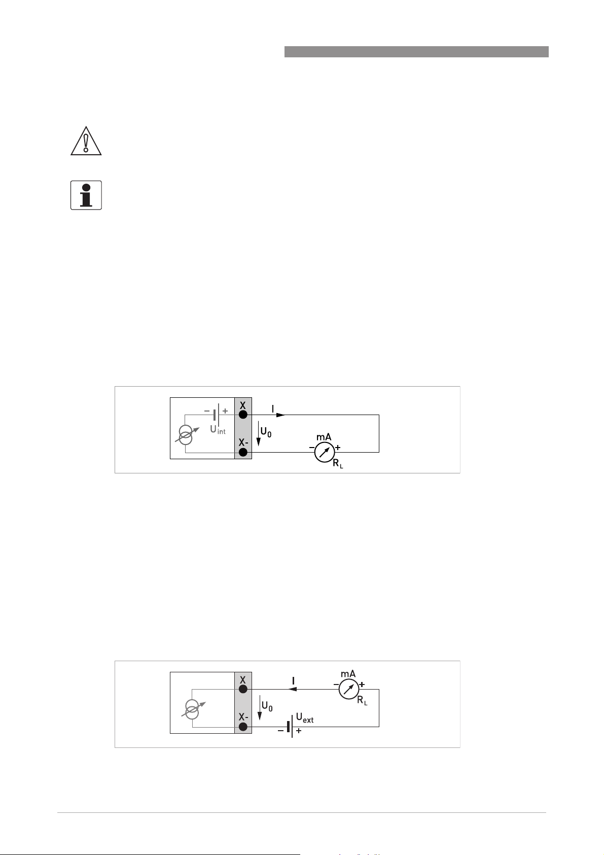
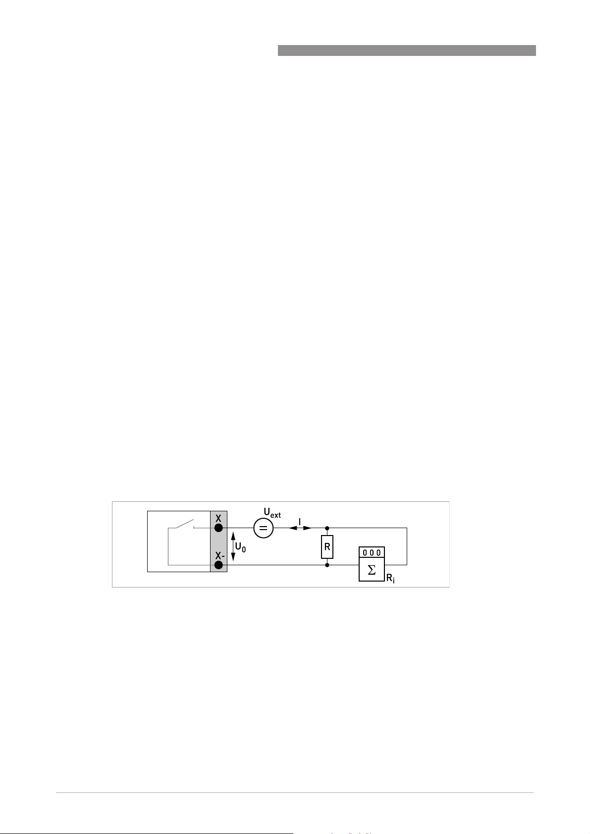
4.8.1 Current output
INFORMATION!
The current outputs must be connected depending on the version! Which I/O versions and
inputs/outputs are installed in your signal converter are indicated on the sticker in the cover of
the terminal compartment.
For Modular I/Os, the current output at terminal C must be configured to active/passive before
connecting it.
• All outputs are electrically isolated from each other and from all other circuits.
• All operating data and functions can be adjusted.
• Passive mode:
External power supply required: U
• Active mode:
Load impedance R
≤ 400 Ω at I ≤ 22 mA for Ex i outputs
R
L
• Self-monitoring: interruption or load impedance too high in the current output loop
• Error message possible via status output, error indication on LC display.
• Alarm signal can be adjusted. Default setting: 3.5 mA
• Automatic range conversion via threshold or control input is available for current output at
terminal A or B. The range for the threshold is between 5 and 80% of Q
hysteresis (corresponding ratio from smaller to larger range of 1:20 to 1:1.25).
Signalling of the active range possible via a status output (adjustable).
• Forward/reverse flow measurement (F/R mode) is possible.
≤ 1kΩ at I ≤ 22 mA;
L
≤ 30 VDC at I ≤ 22 mA
ext
100%
MFC 400
, ± 0...5%
INFORMATION!
For further information refer to Description of the inputs and outputs on page 38
Technical data on page 119
.
and refer to
DANGER!
For devices used in hazardous areas, additional safety notes apply; please refer to the Ex
documentation.
32
www.krohne.com 01/2021 - 4002075808 - MA MFC400 ER2.1 R08 en
Page 33

MFC 400
4.8.2 Pulse output and frequency output
INFORMATION!
Depending on the version, the pulse and frequency outputs must be connected passively or
actively or according to NAMUR EN 60947-5-6! Which I/O version and inputs/outputs are
installed in your signal converter are indicated on the sticker in the cover of the terminal
compartment.
For Modular I/Os, the pulse output or frequency output at terminal D must be configured to
active/passive/NAMUR before connecting it.
• All outputs are electrically isolated from each other and from all other circuits.
• All operating data and functions can be adjusted.
• Passive mode:
External power supply required: U
I ≤ 20 mA at f ≤ 10 kHz (over range up to f
I ≤ 100 mA at f ≤ 100 Hz
• Active mode:
Use of the internal power supply: U
I ≤ 20 mA at f ≤ 10 kHz (over range up to f
I ≤ 20 mA at f ≤ 100 Hz
• NAMUR mode:
Passive in accordance with EN 60947-5-6;
f ≤ 10 kHz (over range up to f
• Scaling:
Frequency output: in pulses per time unit (e.g. 1000 pulses/s at Q
Pulse output: quantity per pulse
• Pulse width:
symmetric (pulse duty factor 1:1, independent of output frequency),
automatic (with fixed pulse width, duty factor approx. 1:1 at Q
fixed (pulse width adjustable as required from 0.05 ms...2 s)
• When pulse shape is set to fixed, then the maximum pulse rate/frequency is limited to
1/(1.5 * pulse width).
• If output pulse rate is limited, pulses are cached and will continue to be transmitted even
when the flow rate falls to zero.
• Forward/reverse flow measurement (F/R mode) is possible.
• All pulse and frequency outputs can also be used as a status output / limit switch.
max
≤ 32 VDC;
ext
=24VDC;
nom
≤ 12 kHz)
ELECTRICAL CONNECTIONS
≤ 12 kHz);
max
≤ 12 kHz);
max
);
100%
) or
100%
4
INFORMATION!
For further information refer to Description of the inputs and outputs on page 38
Technical data on page 119
.
and refer to
DANGER!
For devices used in hazardous areas, additional safety notes apply; please refer to the Ex
documentation.
www.krohne.com01/2021 - 4002075808 - MA MFC400 ER2.1 R08 en
33
Page 34
4
ELECTRICAL CONNECTIONS
4.8.3 Status output and limit switch
INFORMATION!
Depending on the version, the status outputs and limit switches must be connected passively or
actively or according to NAMUR EN 60947-5-6! Which I/O version and inputs/outputs are
installed in your signal converter are indicated on the sticker in the cover of the terminal
compartment.
For Modular I/Os, the status output at terminal D must be configured to active/passive/NAMUR
before connecting it.
• The status outputs / limit switches are electrically isolated from each other and from all
other circuits.
• The output stages of the status outputs / limit switches during simple active or passive
operation behave like relay contacts and can be connected with any polarity.
• All operating data and functions can be adjusted.
• Passive mode:
External power supply required: U
• Active mode:
Use of the internal power supply: U
• NAMUR mode:
Passive in accordance with EN 60947-5-6
≤ 32 VDC at I ≤ 100 mA
ext
=24VDC at I≤ 20 mA
nom
MFC 400
INFORMATION!
For further information refer to Description of the inputs and outputs on page 38
Technical data on page 119
.
and refer to
DANGER!
For devices used in hazardous areas, additional safety notes apply; please refer to the Ex
documentation.
34
www.krohne.com 01/2021 - 4002075808 - MA MFC400 ER2.1 R08 en
Page 35
MFC 400
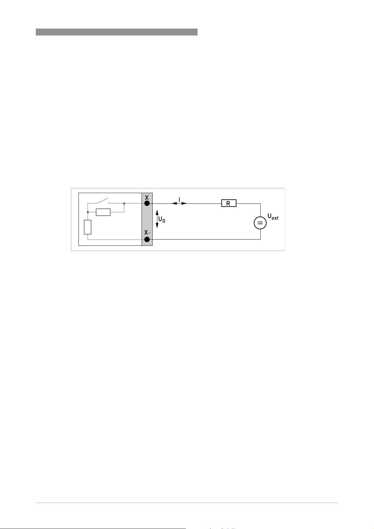
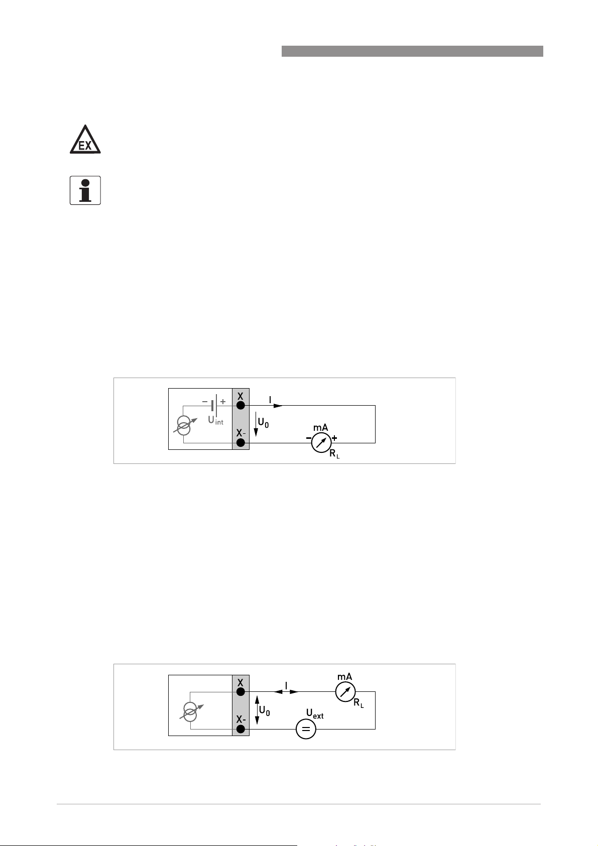
4.8.4 Control input
INFORMATION!
Depending on the version, the control inputs must be connected passively or actively or
according to NAMUR EN 60947-5-6! Which I/O version and inputs/outputs are installed in your
signal converter are indicated on the sticker in the cover of the terminal compartment.
• All control inputs are electrically isolated from each other and from all other circuits.
• All operating data and functions can be adjusted.
• Passive mode:
External power supply required: U
• Active mode:
Use of the internal power supply: U
• NAMUR mode:
In accordance with EN 60947-5-6
Active control input to NAMUR EN 60947-5-6: signal converter monitors cable breaks and
short circuits according to EN 60947-5-6. Errors indicated on LC display. Error messages
possible via status output.
≤ 32 VDC
ext
nom
ELECTRICAL CONNECTIONS
=24VDC
4
INFORMATION!
For further information refer to Description of the inputs and outputs on page 38
Technical data on page 119
.
and refer to
DANGER!
For devices used in hazardous areas, additional safety notes apply; please refer to the Ex
documentation.
www.krohne.com01/2021 - 4002075808 - MA MFC400 ER2.1 R08 en
35
Page 36
4
ELECTRICAL CONNECTIONS
4.9 Electrical connection of the inputs and outputs
CAUTION!
I/O connections must not be connected to DC power supply networks.
INFORMATION!
Assembly materials and tools are not part of the delivery. Use the assembly materials and tools
in compliance with the applicable occupational health and safety directives.
4.9.1 Field housing, electrical connection of the inputs and outputs
DANGER!
All work on the electrical connections may only be carried out with the power disconnected.
Take note of the voltage data on the nameplate!
INFORMATION!
For frequencies above 100 Hz, shielded cables are to be used in order to reduce effects from
electrical interferences (EMC).
MFC 400
36
Figure 4-5: Terminal compartment for inputs and outputs in field housing
1 Open the housing cover.
2 Push the prepared cable through the cable entry and connect the necessary conductors.
3 Connect the shield if necessary.
4 Close the touch guard.
5 Close the housing cover.
INFORMATION!
Each time a housing cover is opened, the thread should be cleaned and greased. Use only resinfree and acid-free grease.
Ensure that the housing gasket is properly fitted, clean and undamaged.
www.krohne.com 01/2021 - 4002075808 - MA MFC400 ER2.1 R08 en
Page 37

MFC 400
4.9.2 Laying electrical cables correctly
Figure 4-6: Protect housing from dust and water
1 Lay the cable in a loop just before the housing.
2 Tighten the screw connection of the cable entry securely.
3 Never mount the housing with the cable entries facing upwards.
4 Seal cable entries that are not needed with a plug.
ELECTRICAL CONNECTIONS
4
www.krohne.com01/2021 - 4002075808 - MA MFC400 ER2.1 R08 en
37
Page 38

4
ELECTRICAL CONNECTIONS
4.10 Description of the inputs and outputs
4.10.1 Important notes
INFORMATION!
Depending on the version, the inputs/outputs must be connected passively or actively or
according to NAMUR EN 60947-5-6! Which I/O version and inputs/outputs are installed in your
signal converter are indicated on the sticker in the cover of the terminal compartment.
• All groups are electrically isolated from each other and from all other input and output
circuits.
• Passive mode: An external power supply is necessary to operate (activation) the subsequent
devices (U
• Active mode: The signal converter supplies the power for operation (activation) of the
subsequent devices, observe max. operating data.
• Terminals that are not used should not have any conductive connection to other electrically
conductive parts.
DANGER!
For devices used in hazardous areas, additional safety notes apply; please refer to the Ex
documentation.
ext
).
MFC 400
I
I
a
P
a
P
N
S
a
S
N
C
a
C
N
Table 4-6: Description of used abbreviations
Current output active or passive
p
P
Pulse/frequency output active or passive
p
Pulse/frequency output passive according to NAMUR EN 60947-5-6
S
Status output/limit switch active or passive
p
Status output/limit switch passive according to NAMUR EN 60947-5-6
C
Control input active or passive
p
Control input active according to NAMUR EN 60947-5-6:
Signal converter monitors cable breaks and short circuits according to EN 60947-5-6.
Errors indicated on LC display. Error messages possible via status output.
38
www.krohne.com 01/2021 - 4002075808 - MA MFC400 ER2.1 R08 en
Page 39

MFC 400
4.10.2 Description of the electrical symbols
mA meter
0...20 mA or 4...20 mA and other
RL is the internal resistance of the measuring point including the cable
resistance
DC voltage source (U
ELECTRICAL CONNECTIONS
), external power supply, any connection polarity
ext
4
DC voltage source (U
connection diagrams
Internal DC voltage source
Controlled internal power source in the device
Electronic or electromagnetic counter
At frequencies above 100 Hz, shielded cables must be used to connect the
counters.
Ri Internal resistance of the counter
Button, N/O contact or similar
Table 4-7: Description of the electrical symbols
), observe connection polarity according to
ext
www.krohne.com01/2021 - 4002075808 - MA MFC400 ER2.1 R08 en
39
Page 40
4
ELECTRICAL CONNECTIONS
4.10.3 Modular inputs/outputs and bus systems
CAUTION!
•
Observe connection polarity.
•
Configure the outputs at terminal C and D before connecting them.
INFORMATION!
•
For further information refer to Description of the inputs and outputs on page 32
The electrical connection of the bus systems are described in the supplementary instructions
•
of the respective bus system.
Current output active (only current output terminals C/C- have HART® capability),
modular I/Os
• U
int, nom
• I ≤ 22 mA
• R
L
• X designates the connection terminals A, B or C, depending on the version of the signal
converter.
=24VDC
≤ 1kΩ
MFC 400
.
Figure 4-7: Current output active I
a
Current output passive (only current output terminals C/C- have HART® capability),
modular I/Os
• U
• I ≤ 22 mA
• U
• R
• X designates the connection terminals A, B or C, depending on the version of the signal
Figure 4-8: Current output passive I
≤ 30 VDC
ext
≥ 1.8 V
0
≤ (U
L
ext-U0
converter.
)/I
max
p
40
www.krohne.com 01/2021 - 4002075808 - MA MFC400 ER2.1 R08 en
Page 41

MFC 400
ELECTRICAL CONNECTIONS
INFORMATION!
•
Compact and field housing versions:
Compact and field housing versions: Shield connected via the cable terminals in the terminal
Compact and field housing versions:Compact and field housing versions:
compartment.
•
Any connection polarity.
Pulse/frequency output active, modular I/Os
• U
• f
• f
• If the following maximum load impedance R
• The minimum load impedance R
• X designates the connection terminals A, B or D, depending on the version of the signal
=24VDC
nom
in the operating menu set to f
max
max
≤ 100 Hz:
I ≤ 20 mA
open:
I ≤ 0.05 mA
closed:
U
max
=24V at I=20mA
0, nom
in operating menu set to 100 Hz < f
max
≤ 10 kHz:
I ≤ 20 mA
open:
I ≤ 0.05 mA
closed:
U
U
U
= 22.5 V at I = 1 mA
0, nom
= 21.5 V at I = 10 mA
0, nom
=19V at I=20mA
0, nom
L, max
be reduced accordingly by parallel connection of R:
f ≤ 100 Hz: R
f ≤ 1kHz: R
L, max
f ≤ 10 kHz: R
R
L, min=U0/Imax
L, max
L, max
=47kΩ
=10kΩ
=1kΩ
is calculated as follows:
L, min
converter.
is exceeded, the load impedance RL must
4
Figure 4-9: Pulse/frequency output active P
a
www.krohne.com01/2021 - 4002075808 - MA MFC400 ER2.1 R08 en
41
Page 42
4
ELECTRICAL CONNECTIONS
Pulse/frequency output passive, modular I/Os
• U
• f
• f
• If the following maximum load impedance R
• The minimum load impedance R
• Can also be set as status output. For the electrical connection refer to status output
• X designates the connection terminals A, B or D, depending on the version of the signal
≤ 32 VDC
ext
in the operating menu set to f
max
I ≤ 100 mA
open:
I ≤ 0.05 mA at U
=32VDC
ext
closed:
U
U
=0.2V at I≤ 10 mA
0, max
=2V at I≤ 100 mA
0, max
in operating menu set to 100 Hz < f
max
open:
I ≤ 0.05 mA at U
=32VDC
ext
closed:
U
U
U
=1.5V at I≤ 1mA
0, max
=2.5V at I≤ 10 mA
0, max
=5V at I≤ 20 mA
0, max
be reduced accordingly by parallel connection of R:
f ≤ 100 Hz: R
f ≤ 1kHz: R
f ≤ 10 kHz: R
R
L, min
=(U
L, max
ext-U0
L, max
L, max
=47kΩ
=10kΩ
=1kΩ
)/I
max
connection diagram.
converter.
≤ 100 Hz:
max
≤ 10 kHz:
max
is exceeded, the load impedance RL must
L, max
is calculated as follows:
L, min
MFC 400
42
Figure 4-10: Pulse/frequency output passive P
www.krohne.com 01/2021 - 4002075808 - MA MFC400 ER2.1 R08 en
p
Page 43

MFC 400
ELECTRICAL CONNECTIONS
INFORMATION!
•
Compact and field housing versions:
Compact and field housing versions: Shield connected via the cable terminals in the terminal
Compact and field housing versions:Compact and field housing versions:
compartment.
•
Any connection polarity.
Pulse/frequency output passive PN NAMUR, modular I/O
• Connection acc. to EN 60947-5-6.
=8.2V ± 0.1 VDC
U
ext
R = 1 kΩ ± 10 Ω
• open:
=0.6mA
I
nom
closed:
=3.8mA
I
nom
• X designates the connection terminals A, B or D, depending on the version of the signal
converter.
4
Figure 4-11: Pulse/frequency output passive PN according to NAMUR EN 60947-5-6
www.krohne.com01/2021 - 4002075808 - MA MFC400 ER2.1 R08 en
43
Page 44

4
ELECTRICAL CONNECTIONS
Status output / limit switch active, modular I/Os
• Observe connection polarity.
• U
• I ≤ 20 mA
• R
• open:
• X designates the connection terminals A, B or D, depending on the version of the signal
=24VDC
int
≤ 47 kΩ
L
I ≤ 0.05 mA
closed:
U
=24V at I=20mA
0, nom
converter.
MFC 400
Figure 4-12: Status output / limit switch active S
a
Status output / limit switch passive, modular I/Os
• Any connection polarity.
• U
• I ≤ 100 mA
• R
• open:
• The output is open when the device is de-energised.
• X designates the connection terminals A, B or D, depending on the version of the signal
=32VDC
ext
=47kΩ
L, max
L, min
=(U
ext-U0
R
I ≤ 0.05 mA at U
closed:
U
U
=0.2V at I≤ 10 mA
0, max
=2V at I≤ 100 mA
0, max
converter.
)/I
=32VDC
ext
max
44
Figure 4-13: Status output / limit switch passive S
www.krohne.com 01/2021 - 4002075808 - MA MFC400 ER2.1 R08 en
p
Page 45
MFC 400
ELECTRICAL CONNECTIONS
Status output / limit switch SN NAMUR, modular I/Os
• Any connection polarity.
• Connection acc. to EN 60947-5-6.
=8.2V ± 0.1 VDC
U
ext
R = 1 kΩ ± 10 Ω
• open:
=0.6mA
I
nom
closed:
=3.8mA
I
nom
• The output is open when the device is de-energised.
• X designates the connection terminals A, B or D, depending on the version of the signal
converter.
4
Figure 4-14: Status output / limit switch SN according to NAMUR EN 60947-5-6
www.krohne.com01/2021 - 4002075808 - MA MFC400 ER2.1 R08 en
45
Page 46

4
ELECTRICAL CONNECTIONS
CAUTION!
Observe connection polarity.
Control input active, modular I/Os
• U
• External contact open:
• Switching point for identifying "contact open or closed":
• X designates the connection terminals A or B, depending on the version of the signal
=24VDC
int
0, nom
=22V
U
External contact closed:
=4mA
I
nom
Contact closed (on): U
Contact open (off): U
0
≥ 12 V at I
0
converter.
≤ 10 V at I
nom
nom
MFC 400
=1.9mA
=1.9mA
Figure 4-15: Control input active C
1 Signal
a
Control input passive, modular I/Os
• 3V≤ U
• I
max
I
max
• Switching point for identifying "contact open or closed":
Contact open (off): U
Contact closed (on): U
• X designates the connection terminals A or B, depending on the version of the signal
converter.
≤ 32 VDC
ext
=9.5mA at U
=9.5mA at U
≤ 24 V
ext
≤ 32 V
ext
≤ 2.5 V at I
0
0
≥ 3V at I
nom
nom
=1.9mA
=1.9mA
46
Figure 4-16: Control input passive C
1 Signal
p
www.krohne.com 01/2021 - 4002075808 - MA MFC400 ER2.1 R08 en
Page 47

MFC 400
ELECTRICAL CONNECTIONS
CAUTION!
Observe connection polarity.
Control input active CN NAMUR, modular I/Os
• Connection acc. to EN 60947-5-6:
• Switching point for identifying "contact open or closed":
Contact open (off): U
Contact closed (on): U
0, nom
0, nom
=6.3V at I
=6.3V at I
• Detection of cable break:
≥ 8.1 V at I ≤ 0.1 mA
U
0
• Detection of cable short circuit:
≤ 1.2 V at I ≥ 6.7 mA
U
0
• X designates the connection terminals A or B, depending on the version of the signal
converter.
nom
nom
<1.9mA
>1.9mA
4
Figure 4-17: Control input active CN according to NAMUR EN 60947-5-6
www.krohne.com01/2021 - 4002075808 - MA MFC400 ER2.1 R08 en
47
Page 48
4
ELECTRICAL CONNECTIONS
4.10.4 Ex i inputs/outputs
DANGER!
For devices used in hazardous areas, additional safety notes apply; please refer to the Ex
documentation.
INFORMATION!
For further information refer to Description of the inputs and outputs on page 32
Current output active (only current output terminals C/C- have HART® capability), Ex i
I/Os
• Observe connection polarity.
• U
int, nom
• I ≤ 22 mA
• R
L
• X designates the connection terminals A or C, depending on the version of the signal
converter.
=21VDC
≤ 400 Ω
MFC 400
.
Figure 4-18: Current output active Ia Ex i
Current output passive (only current output terminals C/C- have HART® capability),
Ex i I/Os
• Any connection polarity.
• U
• I ≤ 22 mA
• U
• R
• X designates the connection terminals A or C, depending on the version of the signal
Figure 4-19: Current output passive Ip Ex i
≤ 30 VDC
ext
≥ 4V
0
≤ (U
L
ext-U0
converter.
)/I
max
48
www.krohne.com 01/2021 - 4002075808 - MA MFC400 ER2.1 R08 en
Page 49

MFC 400
ELECTRICAL CONNECTIONS
DANGER!
For devices used in hazardous areas, additional safety notes apply; please refer to the Ex
documentation.
INFORMATION!
•
Compact and field housing versions:
Compact and field housing versions: Shield connected via the cable terminals in the terminal
Compact and field housing versions:Compact and field housing versions:
compartment.
•
Any connection polarity.
Pulse/frequency output passive PN NAMUR, Ex i I/Os
• Connection according to EN 60947-5-6.
=8.2V ± 0.1 VDC
U
ext
R = 1 kΩ ± 10 Ω
• open:
=0.43mA
I
nom
closed:
=4.5mA
I
nom
• X designates the connection terminals B or D, depending on the version of the signal
converter.
4
Figure 4-20: Pulse/frequency output passive PN according to NAMUR EN 60947-5-6 Ex i
www.krohne.com01/2021 - 4002075808 - MA MFC400 ER2.1 R08 en
49
Page 50

4
ELECTRICAL CONNECTIONS
INFORMATION!
•
Any connection polarity.
Status output / limit switch SN NAMUR, Ex i I/Os
• Connection according to EN 60947-5-6.
=8.2V ± 0.1 VDC
U
ext
R = 1 kΩ ± 10 Ω
• open:
I
=0.43mA
nom
closed:
I
=4.5mA
nom
• The output is closed when the device is de-energised.
• X designates the connection terminals B or D, depending on the version of the signal
converter.
MFC 400
Figure 4-21: Status output / limit switch SN according to NAMUR EN 60947-5-6 Ex i
50
www.krohne.com 01/2021 - 4002075808 - MA MFC400 ER2.1 R08 en
Page 51

MFC 400
ELECTRICAL CONNECTIONS
DANGER!
For devices used in hazardous areas, additional safety notes apply; please refer to the Ex
documentation.
INFORMATION!
•
Any connection polarity.
Control input passive, Ex i I/Os
• 5.5 V ≤ U
• I
=6mA at U
max
=6.5mA at U
I
max
• Switching point for identifying "contact open or closed":
Contact open (off): U
Contact closed (on): U
• X designates the connection terminals B, if available.
≤ 30 VDC
ext
≤ 24 V
ext
≤ 32 V
ext
≤ 3.5 V at I ≤ 0.5 mA
0
≥ 5.5 V at I ≥ 4mA
0
4
Figure 4-22: Control input passive Cp Ex i
1 Signal
4.10.5 HART connection
INFORMATION!
For modular I/O and Ex i I/O, only the output module for the connection terminals C/C- has
®
HART
HART® connection active (point-to-point)
Figure 4-23: HART® connection active (Ia)
1 Modular I/O: terminals C- and C
2 HART
The parallel resistance to the HART® communicator must be R ≥ 230 Ω.
capability.
®
communicator
www.krohne.com01/2021 - 4002075808 - MA MFC400 ER2.1 R08 en
51
Page 52
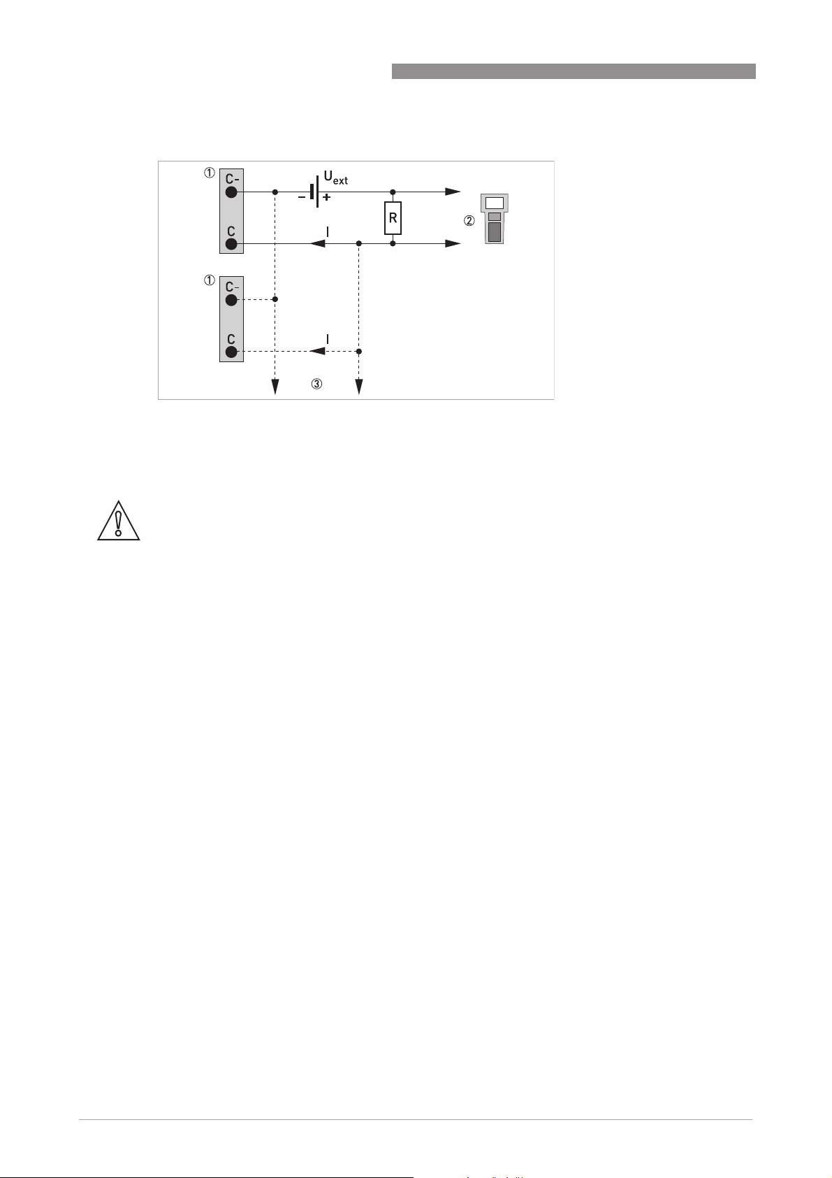
4
ELECTRICAL CONNECTIONS
HART® connection passive (Multi-Drop mode)
Figure 4-24: HART® connection passive (Ip)
1 Modular I/O: terminals C- and C
2 HART
3 Other devices with HART
®
communicator
®
capability
MFC 400
CAUTION!
For Multi-Drop mode disable the loop current mode (C4.2).
• I: I0%≥ 4mA
• U
≤ 32 VDC
ext
• R ≥ 230 Ω
52
www.krohne.com 01/2021 - 4002075808 - MA MFC400 ER2.1 R08 en
Page 53
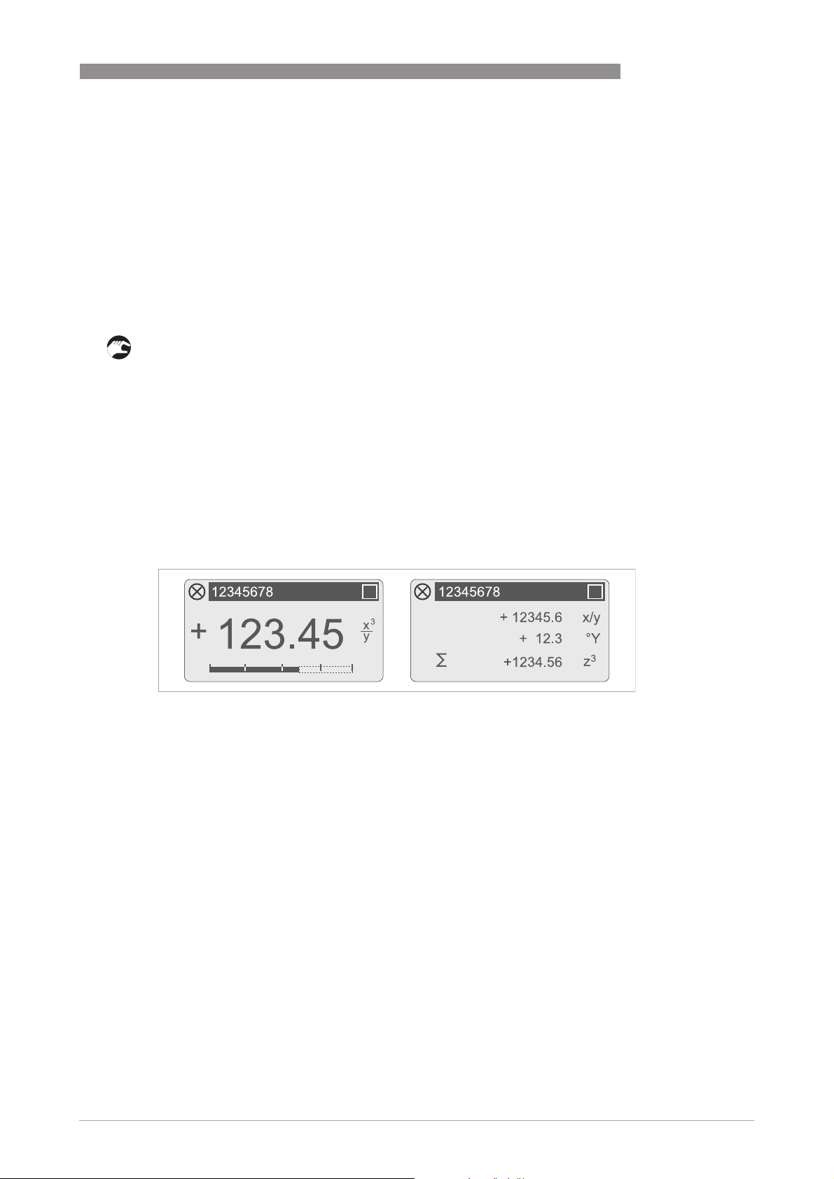
MFC 400
5.1 Switching on the power
Before connecting to power, please check that the system has been correctly installed.
This includes:
• The device must be mounted in compliance with the regulations.
• The power connections must have been made in compliance with the regulations.
• The electrical terminal compartments must be secured and the covers have been screwed
on.
• Check that the electrical operating data of the power supply are correct.
• Switching on the power.
5.2 Starting the signal converter
The measuring device, consisting of the flow sensor and the signal converter, is supplied ready
for operation. All operating data have been set at the factory in accordance with your order
specifications.
START-UP
5
When the power is switched on as well as continuously during operation, a self test is carried
out. After that the device immediately begins measuring, and the current values are displayed.
Figure 5-1: Displays in measuring mode (examples for 2 or 3 measured values)
x, y and z denote the units of the measured values displayed
It is possible to change between the two measured value windows, the trend display and a status
page containing status messages from continuously running diagnostic functions by pressing
the keys ↑ and ↓. For possible status messages, their meaning and cause refer to
information and status messages
on page 103.
Diagnostic
www.krohne.com01/2021 - 4002075808 - MA MFC400 ER2.1 R08 en
53
Page 54
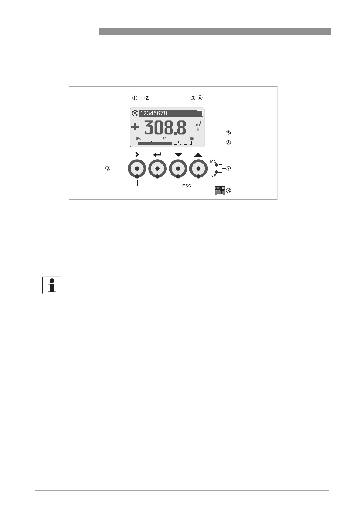
6
OPERATION
6.1 Display and operating elements
Figure 6-1: Display and operating elements (Example: flow indication with 2 measuring values)
1 Indicates the device status
2 Tag number (is only indicated if this number was entered previously by the operator)
3 Wireless interface indicator (e.g. Bluetooth
4 Indicates the key and lock status
5 1st measured variable in large representation
6 Bargraph indication
7 Status LEDs MS (S1) and NS (S2) (interface status, functionality depends on signal converter version)
8 Interface to the GDC bus (not present in all signal converter versions)
9 Operating keys, optical and mechanical (see table below for function and representation in text)
MFC 400
®
)
INFORMATION!
•
The switching point for the 4 optical keys is located directly in front of the glass. It is
recommended to activate the keys at right angles to the front. Touching them from the side
can cause incorrect operation.
•
After 5 minutes of inactivity, there is an automatic return to measuring mode. Previously
changed data is not saved.
54
www.krohne.com 01/2021 - 4002075808 - MA MFC400 ER2.1 R08 en
Page 55

MFC 400
OPERATION
6
Key Measuring mode Menu mode Submenu or function
mode
> Switch from measuring
mode to menu mode;
press key (optical keys
for 2.5 s), "A0.0.0 Quick
Setup" menu is then
displayed
^ Reset display; "Quick
Access" function
↓ or ↑ Switch between display
pages: measured
value 1 + 2, trend page
and status page
Esc (> + ↑) - - Return to menu mode
Table 6-1: Description of functionality of operating keys
Access to displayed
menu, then 1st
submenu is displayed
Return to measuring
mode but prompt
whether the data should
be saved
Select menu Select submenu or
Access to displayed
submenu or function
Press 1 to 3 times,
return to menu mode,
data saved
function
without acceptance of
data
Icon Description
Optical or mechanical key pressed
Parameter and data
mode
For numerical values,
move cursor
(highlighted in blue) one
position to the right
Return to submenu or
function, data saved
Use cursor highlighted
in blue to change
number, unit, property
and to move the decimal
point
Return to submenu or
function without
acceptance of data
Optical keys disabled (only displayed while pressed)
Lock jumper set
Device in SIL mode (unverified safe configuration)
Device in SIL mode (verified locked safe configuration)
Infrared interface enabled
Configuration checked and stored
Table 6-2: Indication of key and lock status
www.krohne.com01/2021 - 4002075808 - MA MFC400 ER2.1 R08 en
55
Page 56
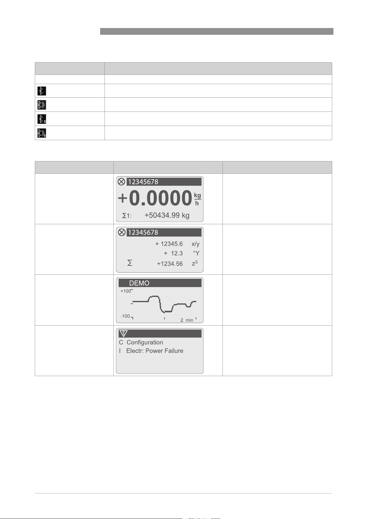
6
OPERATION
Icon Description
<None> Wireless interface turned off
Bluetooth® interface ready for connection, read & write mode
Bluetooth® interface connected, read & write mode
Bluetooth® interface ready for connection, read-only mode
Bluetooth® interface connected, read-only mode
Table 6-3: Indication of Bluetooth® connection status
Name Screen Display in menu mode
1st measuring page Menu for device configuration
MFC 400
2nd measuring page Menu for device configuration
Graphic page Menu for device configuration
Status message page Menu for status messages with detailed
Table 6-4: Indication of display pages
status information
56
www.krohne.com 01/2021 - 4002075808 - MA MFC400 ER2.1 R08 en
Page 57

MFC 400
6.1.1 Display in measuring mode with 2 or 3 measured values
Figure 6-2: Example for display in measuring mode with 2 or 3 measured values
1 Indicates a possible status message in the status list
2 Tag number (is only indicated if this number was entered previously by the operator)
3 1st measured variable in large representation
4 Bargraph indication
5 Depiction with 3 measured values
6.1.2 Display for selection of submenu and functions, 3 lines
OPERATION
6
Figure 6-3: Display for selection of submenu and functions, 3 lines
1 Indicates a possible status message in the status list
2 Menu, submenu or function name
3 Number relating to 6
4 Indicates position within menu, submenu or function list
5 Next menu(s), submenu or function
(_ _ _ signals in this line the end of the list)
6 Current menu(s), submenu or function
7 Previous menu(s), submenu or function
(_ _ _ signals in this line the beginning of the list)
www.krohne.com01/2021 - 4002075808 - MA MFC400 ER2.1 R08 en
57
Page 58

6
OPERATION
6.1.3 Display when setting parameters, 4 lines
Figure 6-4: Display when setting parameters, 4 lines
1 Current menu(s), submenu or function
2 Number relating to 7
3 Denotes factory setting
4 Denotes permissible value range
5 Permissible value range for numeric values
6 Currently set value, unit or function (when selected, appears with white text, blue background)
This is where the data is changed.
7 Current parameter
8 Factory setting of parameter
MFC 400
6.1.4 Display when previewing parameters, 4 lines
Figure 6-5: Display when previewing parameters, 4 lines
1 Current menu(s), submenu or function
2 Number relating to 6
3 Denotes the status of the parameter
4 Next parameter
5 Currently set data from 6
6 Current parameter (for selection press key >; then see previous chapter)
7 Factory setting of parameter
Icon Description
Changed parameter
58
Factory parameter (not changeable)
Lock parameter by write access authentication
Lock parameter by jumper or SIL Mode
Table 6-5: Description of parameter icons
www.krohne.com 01/2021 - 4002075808 - MA MFC400 ER2.1 R08 en
Page 59

MFC 400
6.2 Menu structure
A0.0.0 Quick Setup
A0.0.0 Quick Setup
A0.0.0 Quick SetupA0.0.0 Quick Setup
A1.0.0 Language
A1.0.0 Language
A1.0.0 LanguageA1.0.0 Language
A2.0.0 Reset
A2.0.0 Reset
A2.0.0 ResetA2.0.0 Reset
A3.0.0 Configuration
A3.0.0 Configuration
A3.0.0 ConfigurationA3.0.0 Configuration
A4.0.0 Safety Mode
A4.0.0 Safety Mode
A4.0.0 Safety ModeA4.0.0 Safety Mode
A5.0.0 SIL Verification
A5.0.0 SIL Verification
A5.0.0 SIL VerificationA5.0.0 SIL Verification
A6.0.0 Unlock Device
A6.0.0 Unlock Device
A6.0.0 Unlock DeviceA6.0.0 Unlock Device
A7.0.0 Calibrate Zero
A7.0.0 Calibrate Zero
A7.0.0 Calibrate ZeroA7.0.0 Calibrate Zero
A8.0.0 Operation Mode
A8.0.0 Operation Mode
A8.0.0 Operation ModeA8.0.0 Operation Mode
Table 6-6: Menu "Quick Setup"
A2.1.0 Reset Errors
A2.2.0 Stop All Simulations
A2.3.0 All Totalisers
A2.4.0 Totaliser 1
A2.5.0 Totaliser 2
A2.6.0 Totaliser 3
A2.7.0 Reset BT Lockout
A3.1.0 Tag
A3.2.0 Measurement
A3.3.0 Range
A3.4.0 Alarm Code
A3.5.0 Low Flow Cutoff
A3.6.0 Damping
A3.7.0 Terminals C Type
A3.8.0 Flow Direction
OPERATION
6
www.krohne.com01/2021 - 4002075808 - MA MFC400 ER2.1 R08 en
59
Page 60

6
OPERATION
B0.0.0 Test
B0.0.0 Test
B0.0.0 TestB0.0.0 Test
B1.0.0 Status
B1.0.0 Status
B1.0.0 StatusB1.0.0 Status
B1.1.0 Status Log
B1.2.0 Change Log
B1.3.0 Zero Calibration Log
B1.4.0 Last Density Calib.
B1.5.0 Act. Operat. Mode
B1.6.0 Safety State
B1.7.0 Bluetooth
B2.0.0 Actual Values
B2.0.0 Actual Values
B2.0.0 Actual ValuesB2.0.0 Actual Values
B2.1.0 Operating Hours
B2.2.0 Date and Time
B2.3.0 Mass Flow
B2.4.0 Volume Flow
B2.5.0 Velocity
B2.6.0 Density
B2.7.0 Temperature
B2.8.0 Strain 1
B2.9.0 Strain 2
B2.10.0 Tube Frequency
B2.11.0 Drive Level
B2.12.0 Sensor A Level
B2.13.0 Sensor B Level
B2.14.0 2 Phase Signal
B2.15.0 Electronics Temp.
B3.0.0 Simulation
B3.0.0 Simulation
B3.0.0 SimulationB3.0.0 Simulation
B3.1.0 Stop All Simulations
B3.2.0 Mass Flow
B3.3.0 Volume Flow
B3.4.0 Density
B3.5.0 Temperature
B3.6.0 Status
B3.7.0 IO A (dep. on output type of terminals A)
B3.8.0 IO B (dep. on output type of terminals B)
B3.9.0 IO C (dep. on output type of terminals C)
B3.10.0 IO D (dep. on output type of terminals D)
MFC 400
60
www.krohne.com 01/2021 - 4002075808 - MA MFC400 ER2.1 R08 en
Page 61

MFC 400
B4.0.0 Sensor Information
B4.0.0 Sensor Information
B4.0.0 Sensor InformationB4.0.0 Sensor Information
B4.1.0 Sensor Type
B4.2.0 Sensor ID
B4.3.0 Sensor Serial No.
B4.4.0 V No. Sensor
B4.5.0 Sensor Revision
B4.6.0 Nominal Mass Flow
B4.7.0 Max. Allowed Temp.
B4.8.0 Min. Allowed Temp.
B4.9.0 Max. Rec. Temp.
B4.10.0 Min. Rec. Temp.
B4.11.0 Calibration Date
B4.12.0 Flow Calibration
B4.13.0 Density Calibration
B5.0.0 Electr. Information
B5.0.0 Electr. Information
B5.0.0 Electr. InformationB5.0.0 Electr. Information
B5.1.0 C Number
B5.2.0 Sensor Electronics
B5.3.0 HART (if available) or
B5.4.0 V No. Converter
B5.5.0 Electronic Revision
B5.6.0 Bluetooth (if available)
Table 6-7: Menu "Test"
OPERATION
6
C0.0.0 Setup
C0.0.0 Setup
C0.0.0 SetupC0.0.0 Setup
C1.0.0 Process Input
C1.0.0 Process Input
C1.0.0 Process InputC1.0.0 Process Input
C2.0.0 I/O
C2.0.0 I/O
C2.0.0 I/OC2.0.0 I/O
C3.0.0 Totalisers
C3.0.0 Totalisers
C3.0.0 TotalisersC3.0.0 Totalisers
C1.1.0 Flow
C1.2.0 Density
C1.3.0 Concentration
C1.4.0 System Control*
C1.5.0 Diagnostics
C2.1.0 Hardware
C2.2.0 Terminals A
C2.3.0 Terminals B
C2.4.0 Terminals C
C2.5.0 Terminals D
C3.1.0 Totaliser 1
C3.2.0 Totaliser 2
C3.3.0 Totaliser 3
www.krohne.com01/2021 - 4002075808 - MA MFC400 ER2.1 R08 en
61
Page 62

6
OPERATION
Table 6-8: Menu "Setup"
C4.0.0 HART (if available)
C4.0.0 HART (if available)
C4.0.0 HART (if available)C4.0.0 HART (if available)
C4.1.0 HART
C4.2.0 Loop Current Mode
C4.3.0 Identification
C4.4.0 HART Dyn. Variables
C5.0.0 Display
C5.0.0 Display
C5.0.0 DisplayC5.0.0 Display
C5.1.0 Language
C5.2.0 Contrast
C5.3.0 Optical Keys
C5.4.0 Backlight
C5.5.0 Default Display
C5.6.0 1st Meas. Page
C5.7.0 2nd Meas. Page
C5.8.0 Graphic Page
C6.0.0 Device
C6.0.0 Device
C6.0.0 DeviceC6.0.0 Device
C6.1.0 Tag
C6.2.0 Reset Errors
C6.3.0 Config. Management
C6.4.0 Special Functions
C6.5.0 Units
C6.6.0 Status Groups
C7.0.0 SIL**
C7.0.0 SIL**
C7.0.0 SIL**C7.0.0 SIL**
C7.1.0 Configuration
C7.2.0 Safety Mode
C7.3.0 SIL Verification
C7.4.0 Unlock Device
C7.5.0 Unlock Password
C8.0.0 Bluetooth***
C8.0.0 Bluetooth***
C8.0.0 Bluetooth***C8.0.0 Bluetooth***
C8.1.0 Access Level
C8.2.0 Password
C8.3.0 LED Signalling
C8.4.0 Reset BT Lockout
MFC 400
62
* only available if expert mode is enabled
** only available in device variants certified according to IEC 61508
*** may not be available in all countries
www.krohne.com 01/2021 - 4002075808 - MA MFC400 ER2.1 R08 en
Page 63
MFC 400
6.3 Function tables
INFORMATION!
•
The following tables describe the functions of the standard device with HART® connection.
The functions for Modbus, Foundation Fieldbus, Profibus and Profinet IO are described in detail in the
corresponding supplementary instructions.The functions for Modbus, Foundation Fieldbus and Profibus
are described in detail in the corresponding supplementary instructions.
•
Depending on the device version, not all functions are available.
•
The device provides an expert mode. Some functions marked with * are only available in expert mode.
6.3.1 Menu "Quick Setup"
Function Description and selection
A0.0.0 Quick Setup
A0.0.0 Quick Setup
A0.0.0 Quick SetupA0.0.0 Quick Setup
A1.0.0 Language
A1.0.0 Language Select language.
A1.0.0 LanguageA1.0.0 Language
Available languages: English, German, French, Danish, Spanish, Italian,
Dutch, Polish, Portuguese, Swedish, Turkish, Norwegian
A2.0.0 Reset
A2.0.0 Reset
A2.0.0 ResetA2.0.0 Reset
A2.1.0 Reset Errors Reset Errors?
A2.2.0 Stop All Simulations Stop all running simulations?
A2.3.0 All Totalisers Reset all Totalisers?
A2.4.0 Totaliser 1 Reset Totaliser 1?
A2.5.0 Totaliser 2 Reset Totaliser 2?
A2.6.0 Totaliser 3 Reset Totaliser 3?
A2.7.0 Reset BT Lockout
A3.0.0 Configuration
A3.0.0 Configuration Safety relevant parameters for SIL setup.
A3.0.0 ConfigurationA3.0.0 Configuration
A3.1.0 Tag
A3.2.0 Measurement Measurement value for current output at terminals C.
Select: No / Yes
Select: No / Yes
Select: No / Yes
Select: No / Yes
Select: No / Yes
Select: No / Yes
Resets Bluetooth® Lockout mode (caused by repeated login with wrong
password).
Select: No / Yes
Measuring point identifier (Tag no.) (also for HART® operation) will be
displayed in the LCD header (max. 8 digits).
Select: Flow Velocity / Volume Flow / Mass Flow / Temperature / Density /
Sensor Average / Sensor Deviation / Drive Level / Tube Frequency /
Strain1/ Strain2/ 2Phase Signal
OPERATION
6
Depending on the settings for the concentration measurement, the following
measurements are possible:
Concentration 1 / Concentration 2 / Conc. mass flow 1 / Conc. mass flow 2 /
Conc. volume flow 1 / Conc. volume flow 2
A3.3.0 Range Range setting for current output.
Selection depends on the measurement value.
A3.4.0 Alarm Code Specify the failure current output.
Select: Low (3.5 mA) / High (21.5 mA)
A3.5.0 Low Flow Cutoff Sets the measurement to "0" for low values.
x.xxx ± x.xxx%; range: 0.0…20%
(1st value = switching point / 2nd value = hysteresis);
condition: 2nd value ≤ 1st value
www.krohne.com01/2021 - 4002075808 - MA MFC400 ER2.1 R08 en
63
Page 64

6
OPERATION
Function Description and selection
MFC 400
A3.6.0 Damping Setting for the current output.
A3.7.0 Terminals C Type Select: Passive / Active
A3.8.0 Flow Direction Defines polarity of flow direction.
A4.0.0 Safety Mode
A4.0.0 Safety Mode Select: non-SIL Mode / SIL Mode (only available in non expert mode)
A4.0.0 Safety ModeA4.0.0 Safety Mode
A5.0.0 SIL Verification
A5.0.0 SIL Verification Verification of safety relevant parameters and lock of the device.
A5.0.0 SIL VerificationA5.0.0 SIL Verification
A6.0.0 Unlock Device
A6.0.0 Unlock Device Unlock device.
A6.0.0 Unlock DeviceA6.0.0 Unlock Device
A7.0.0 Calibrate Zero
A7.0.0 Calibrate Zero Perform zero calibration.
A7.0.0 Calibrate ZeroA7.0.0 Calibrate Zero
A8.0.0 Operation Mode
A8.0.0 Operation Mode Sets the operating mode.
A8.0.0 Operation ModeA8.0.0 Operation Mode
Table 6-9: Description of menu "Quick Setup"
Range: 0.0…100 s
Select: Forwards (according to the arrow on the flow sensor) / Backwards (in
the opposite direction of the arrow)
For detailed information refer to the "Safety manual".
Note: Only available if "Safety Mode" is changed!
For detailed information refer to the "Safety manual".
Query: Calibrate zero?
Select: Automatic / Factory Calibration / Manual (display last value; set new
value; range: -10…+10%) / Cancel (return without calibration)
Select: Measuring / Standby / Stop
64
www.krohne.com 01/2021 - 4002075808 - MA MFC400 ER2.1 R08 en
Page 65

MFC 400
6.3.2 Menu "Test"
Function Description and selection
B0.0.0 Test
B0.0.0 Test
B0.0.0 TestB0.0.0 Test
B1.0.0 Status
B1.0.0 Status Information
B1.0.0 StatusB1.0.0 Status
B1.1.0 Status Log Log with date and time of status messages that occurred.
B1.2.0 Change Log Shows the changes including date, time and check sum for all settings
B1.3.0 Zero Calibration Log Displays history of zero calibrations performed.
B1.4.0 Last Density Calib. Displays date of last density calibration (yyyy-mmm-ddd).
B1.5.0 Act. Operat. Mode Displays the current operating mode.
B1.6.0 Safety State Displays current state of functional safety configuration (only for SIL
B1.7.0 Bluetooth
B1.7.1 Connection Status
B1.7.2 Last successful login Displays the date and time of the last successful login attempt via
B1.7.3 Last failed login
B1.7.4 MAC Address
B2.0.0 Actual Values
B2.0.0 Actual Values
B2.0.0 Actual ValuesB2.0.0 Actual Values
B2.1.0 Operating Hours Displays the operating hours of the device.
B2.2.0 Date and Time Displays date and time.
B2.3.0 Mass Flow Displays current unfiltered mass flow.
B2.4.0 Volume Flow Displays current unfiltered volume flow.
B2.5.0 Velocity Displays current unfiltered flow velocity.
B2.6.0 Density Displays current unfiltered density.
B2.7.0 Temperature Displays current unfiltered temperature.
B2.8.0 Strain 1 Displays current value for the first strain.
B2.9.0 Strain 2 Displays current value for the second strain.
B2.10.0 Tube Frequency Displays current vibration frequency of the measuring tube.
B2.11.0 Drive Level Displays current drive level to activate vibration.
B2.12.0 Sensor A Level Displays current vibration amplitude of "Sensor A".
B2.13.0 Sensor B Level Displays current vibration amplitude of "Sensor B".
B2.14.0 2 Phase Signal Displays current 2-phase indicator value.
B2.15.0 Electronics Temp. Displays current temperature of the sensor electronics.
and parameters in the signal converter, regardless of the interface
(display, HART
The check sum across all settings is displayed directly below the menu
item.
Showing zero point, temperature, date and time.
device).
Displays information of the Bluetooth® interface.
Displays the current connection state of the Bluetooth® interface (off,
advertising, connected, lockout).
Bluetooth
Displays the date and time of the last failed login attempt via Bluetooth®,
if available.
Displays the MAC (Media-Access-Control) address of the Bluetooth®
interface.
®
, PROFIBUS,...) used.
®
, if available.
OPERATION
6
www.krohne.com01/2021 - 4002075808 - MA MFC400 ER2.1 R08 en
65
Page 66

6
OPERATION
Function Description and selection
B3.0.0 Simulation
B3.0.0 Simulation Displayed values are simulated.
B3.0.0 SimulationB3.0.0 Simulation
B3.1.0 Stop All Simulations Stop all running simulations.
B3.2.0 Mass Flow Simulation of mass flow.
B3.3.0 Volume Flow Simulation of volume flow.
B3.4.0 Density Simulation of density.
B3.5.0 Temperature Simulation of temperature.
Select: No / Yes
Set value (set simulated value in kg/h).
Query: Start Simulation?
Select: Yes (start simulation) / Stop Simulation (stop simulation of mass
flow) / Cancel (exit function without simulation)
Set value (set simulated value in L/h).
Query: Start Simulation?
Select: Yes (start simulation) / Stop Simulation (stop simulation of
volume flow) / Cancel (exit function without simulation)
Set value (set simulated value in kg/m³).
Query: Start Simulation?
Select: Yes (start simulation) / Stop Simulation (stop simulation of
density) / Cancel (exit function without simulation)
Set value (set simulated value in °C).
MFC 400
Query: Start Simulation?
Select: Yes (start simulation) / Stop Simulation (stop simulation of
temperature) / Cancel (exit function without simulation)
B3.6.0 Status Simulation of device status and process value status.
B3.7.0 IO A Sets simulated value of output on terminals A.
B3.8.0 IO B Sets simulated value of output on terminals B.
B3.9.0 IO C Sets simulated value of output on terminals C.
B3.10.0 IO D Sets simulated value of output on terminals D.
B4.0.0 Sensor Information
B4.0.0 Sensor Information
B4.0.0 Sensor InformationB4.0.0 Sensor Information
B4.1.0 Sensor Type Displays the flow sensor type.
B4.2.0 Sensor ID Displays the identification number of the flow sensor.
B4.3.0 Sensor Serial No. Displays the serial number of the flow sensor.
B4.4.0 V No. Sensor Displays the order number of the flow sensor.
B4.5.0 Sensor Revision Displays information of the flow sensor revision.
B4.6.0 Nominal Mass Flow Displays the nominal mass flow of the flow sensor.
B4.7.0 Max. Allowed Temp. Displays the maximum permitted temperature for the flow sensor.
B4.8.0 Min. Allowed Temp. Displays the minimum permitted temperature for the flow sensor.
B4.9.0 Max. Rec. Temp. Displays the maximum recorded flow sensor temperature whilst
B4.10.0 Min. Rec. Temp. Displays the minimum recorded flow sensor temperature whilst
B4.11.0 Calibration Date Displays the date of calibration of the flow sensor.
B4.12.0 Flow Calibration Displays the flow calibration coefficients (CF): CF1...CF27
B4.13.0 Density Calibration Displays the flow sensor density calibration coefficient (DCF):
Set value (select: Failure / Out of Specification / Maintenance Required /
Function Check)
Query: Start Simulation?
Select: Yes (start simulation) / Stop Simulation (stop simulation of
status) / Cancel (exit function without simulation)
powered.
powered.
DCF1...DCF8
66
www.krohne.com 01/2021 - 4002075808 - MA MFC400 ER2.1 R08 en
Page 67

MFC 400
Function Description and selection
B5.0.0 Electr. Information
B5.0.0 Electr. Information Information about the electronics.
B5.0.0 Electr. InformationB5.0.0 Electr. Information
B5.1.0 C Number Displays the C number of the installed electronics.
B5.2.0 Sensor Electronics Displays information of the flow sensor electronics PCB.
B5.3.0 Profibus / Foundation
Fieldbus / Modbus
B5.4.0 V No. Converter Displays the order number of the electronics.
B5.5.0 Electronic Revision Displays the electronic revision (ER) of the electronics.
B5.6.0 Bluetooth
Table 6-10: Description of menu "Test"
Displays information of the Profibus interface or Foundation Fieldbus or
RS 485 / Modbus interface.
Displays the software version of the Bluetooth® interface.
OPERATION
6
www.krohne.com01/2021 - 4002075808 - MA MFC400 ER2.1 R08 en
67
Page 68

6
OPERATION
6.3.3 Menu "Setup"
Function Description and selection
C0.0.0 Setup
C0.0.0 Setup
C0.0.0 SetupC0.0.0 Setup
C1.0.0 Process Input
C1.0.0 Process Input
C1.0.0 Process InputC1.0.0 Process Input
C1.1.0 Flow
C1.1.1 Calibrate Zero Performs zero calibration.
Query: Calibrate zero?
Select: Automatic / Factory Calibration / Manual (display last value; set new value;
range: -10…+10%) / Cancel (return without calibration)
C1.1.2 Zero Add. Offset* Direct setting of zero offset.
Note: Only available if expert mode in C6.4.5 is enabled!
C1.1.3 Flow Correction* Defines additional correction for mass flow.
C1.1.4 Flow Direction Defines polarity of flow direction.
C1.1.5 Process Noise
Damping*
Range: -100.00…+100.00%
Note: Only available if expert mode in C6.4.5 is enabled!
Select: Forwards (according to the arrow on the flow sensor) / Backwards (in the
opposite direction of the arrow)
Sets process noise damping.
Range: 0.01...30.00 s
MFC 400
Note: Only available if expert mode in C6.4.5 is enabled!
C1.1.6 Low Flow Cutoff* Sets the measurement to "0" for low values.
C1.1.7 Press. Supp. Cutoff* Low flow cutoff settings for the pressure suppression.
C1.1.8 Press. Supp. Time* Sets the pressure suppression time.
C1.1.9 Pipe Diameter Sets the pipe diameter in mm to calculate the flow velocity.
C1.2.0 Density
C1.2.1 Calibrate Density Starts density calibration.
C1.2.2 Density Mode Selection of density mode.
C1.2.3 Fixed Density Value Sets the fixed value (e.g. standard density) for the density.
C1.2.4 Ref. Density Temp Sets the reference temperature for the reference density option.
x.xxx%; range: 0.0…20%
Note: Only available if expert mode in C6.4.5 is enabled!
Range: 0.0...10.0%
Note: Only available if expert mode in C6.4.5 is enabled!
Range: 0.0...20.0 s
Note: Only available if expert mode in C6.4.5 is enabled!
Range: 1.00...500.00 mm
Select: 1 Point Calibration / 2nd Calibration Point / Factory Calibration / Cancel
For detailed information refer to
page 86.
Select: Process / Fixed (a fixed value is used for the density (e.g. standard
density)) / Referred (calculates process density based on a reference
temperature) / Standard (calculates standard density based on a reference
temperature and the correction factors)
Available only if density mode "Fixed" has been selected in C1.2.2.
Available only if density mode "Referred" has been selected in C1.2.2.
Density calibration (C1.2.1 Calibrate Density)
on
68
www.krohne.com 01/2021 - 4002075808 - MA MFC400 ER2.1 R08 en
Page 69

MFC 400
Function Description and selection
OPERATION
6
C1.2.5 Ref. Density Slope Sets the slope for the reference density option.
C1.2.6 Standard Density
Temp.
C1.2.7 Standard Density k0 Coefficient k0 to calculate standard density.
C1.2.8 Standard Density k1 Coefficient k1 to calculate standard density.
C1.2.9 Standard Density k2 Coefficient k2 to calculate standard density.
C1.3.0 Concentration For further information refer to supplementary concentration manual.
C1.3.1 Conc. Data Sel. Defines which set of general concentration parameters are active.
C1.3.2 Concentration 1 Defines the function of the concentration measurement.
C1.3.2 Conc. Function Sets the required concentration measurement.
C1.3.2 Conc. Offset Sets an additional offset for the concentration measurement. Can be used to
C1.3.2 Conc. Product Defines which general concentration product is displayed.
C1.3.3 Concentration 2 Defines the function of the concentration measurement.
C1.3.3 Conc. Function Sets the required concentration measurement.
C1.3.3 Conc. Offset Sets an additional offset for the concentration measurement. Can be used to
C1.3.3 Conc. Product Defines which general concentration product is displayed.
C1.3.4 Conc. Data 1 Defines the concentration coefficients used for concentration parameter sets
C1.3.4 CCF01 Defines the use of linear or non-linear coefficients to measure concentration.
C1.3.4 CCF02 Density of "Product A" in g/cm³.
C1.3.4 CCF03 Temperature coefficient for "Product A".
C1.3.4 CCF04 Temperature coefficient squared for "Product A".
C1.3.4 CCF05 Defines "Product B" type.
C1.3.4 CCF06 Density of "Product B" in in g/cm³ (if CCF05 = Other).
C1.3.4 CCF07 Temperature coefficient squared for "Product B" (if CCF05 = Other).
C1.3.4 CCF08 Defines non-linear equation if CCF01 is set to "Non Linear".
C1.3.4 CCF09 Defines non-linear equation if CCF01 is set to "Non Linear". Consult the
Range: 0.0…65.00
Available only if density mode "Referred" has been selected in C1.2.2.
Density reference temperature to calculate standard density.
Available only if density mode "Standard" has been selected in C1.2.2.
Range: 0.0…5000.00
Available only if density mode "Standard" has been selected in C1.2.2.
Range: -100.00…100.00
Available only if density mode "Standard" has been selected in C1.2.2.
Range: -10.0…10.00
Available only if density mode "Standard" has been selected in C1.2.2.
Select: Conc. Data 1 / Conc. Data 2
Select: Off / Brix / % Mass / % Volume / Baume 144 / Baume 145 / % NaOH /
Plato / API / % Alcohol by mass / % Alcohol by volume
correct for differences between the measured value and the reference value.
Range: -100.00…+100.00%
Select: % Of Product A / % Of Product B
Select: Off / Brix / % Mass / % Volume / Baume 144 / Baume 145 / %NaOH / Plato /
API / % Alcohol by mass / % Alcohol by volume
correct for differences between the measured value and the reference value.
Range: -100.00…+100.00%
Select: % Of Product A / % Of Product B
1&2.
Select: Linear / Non Linear
Select: Pure Water / Town Water / Other
manufacturer for settings.
www.krohne.com01/2021 - 4002075808 - MA MFC400 ER2.1 R08 en
69
Page 70

6
OPERATION
Function Description and selection
MFC 400
C1.3.4 CCF10 Defines non-linear equation if CCF01 is set to "Non Linear". Consult the
C1.3.4 CCF11 Defines non-linear equation if CCF01 is set to "Non Linear". Consult the
C1.3.4 CCF12 Defines non-linear equation if CCF01 is set to "Non Linear". Consult the
C1.3.5 Conc. Data 2 Defines the concentration coefficients used for concentration parameter sets
C1.3.5 CCF01 Defines the use of linear or non-linear coefficients to measure concentration.
C1.3.5 CCF02 Density of product A in g/cm³.
C1.3.5 CCF03 Temperature coefficient for "Product A".
C1.3.5 CCF04 Temperature coefficient squared for "Product A".
C1.3.5 CCF05 Defines "Product B" type.
C1.3.5 CCF06 Density of "Product B" in in g/cm³ (if CCF05 = Other).
C1.3.5 CCF07 Temperature coefficient squared for "Product B" (if CCF05 = Other).
C1.3.5 CCF08 Defines non-linear equation if CCF01 is set to "Non Linear".
C1.3.5 CCF09 Defines non-linear equation if CCF01 is set to "Non Linear". Consult the
C1.3.5 CCF10
C1.3.5 CCF11
C1.3.5 CCF12
C1.4.0 System Control* Note: Only available if expert mode in C6.4.5 is enabled!
C1.4.1 Function* Sets the system control action.
manufacturer for settings.
manufacturer for settings.
manufacturer for settings.
1&2.
Select: Linear / Non Linear
Select: Pure Water / Town Water / Other
manufacturer for settings.
Select: Inactive (off) / Flow = 0 (flow to zero)
Note: Only available if expert mode in C6.4.5 is enabled!
C1.4.2 Condition* Sets the condition for activating the system control.
C1.4.3 Max.
Temperature/Density*
C1.4.4 Min.
Temperature/Density*
C1.5.0 Diagnostics
C1.5.1 2 Phase Threshold Sets the process-dependent threshold of the 2 phase signal error message.
C1.5.2 Diagnosis 1 Defines the parameter for the respective diagnosis value.
C1.5.3 Diagnosis 2
Select: Density / Temperature
Note: Only available if expert mode in C6.4.5 is enabled!
Defines the upper limit for the condition selected in C1.4.2.
Note: Only available if expert mode in C6.4.5 is enabled!
Defines the lower limit for the condition selected in C1.4.2.
Note: Only available if expert mode in C6.4.5 is enabled!
Range: 0.0…1000.0
Select: Disabled (goes to zero) / Sensor Average (sensor amplitude A+B) / Sensor
Deviation/ Drive Level/ Tube Frequency/ Strain1/ Strain2/ 2Phase Signal
70
www.krohne.com 01/2021 - 4002075808 - MA MFC400 ER2.1 R08 en
Page 71

MFC 400
OPERATION
Function Description and selection
C2.0.0 I/O
C2.0.0 I/O
C2.0.0 I/OC2.0.0 I/O
C2.1.0 Hardware Configuration of connection terminals.
C2.1.1 Terminals A Select: Off (switched off) / Current Output / Frequency Output / Pulse Output /
C2.1.3 Terminals B Select: Off (switched off) / Current Output / Frequency Output / Pulse Output /
C2.1.5 Terminals C Select: Off (switched off) / Current Output
C2.1.6 Terminals C Type Select: Passive / Active
C2.1.7 Terminals D Select: Off (switched off) / Frequency Output / Pulse Output / Status Output / Limit
C2.1.8 Terminals D Type Select: Active / Passive / NAMUR
C2._.0 Current Out X X represents one of the connection terminals A, B or C.
C2._.1 Measurement Measurement value for current output on terminals X.
Selection depends on signal converter version.
Status Output / Limit Switch / Control Input
Status Output / Limit Switch / Control Input
Switch
_ represents: 1 = Terminals A, 2 = Terminals B, 3 = Terminals C
Select: Flow Velocity / Volume Flow / Mass Flow / Temperature / Density / Sensor
Average / Sensor Deviation / Drive Level / Tube Frequency / Strain 1 / Strain 2 /
2Phase Signal
6
Depending on the settings for the concentration measurement, the following
measurements are possible:
Concentration 1 / Concentration 2 / Conc. mass flow 1 / Conc. mass flow 2 / Conc.
volume flow 1 / Conc. volume flow 2
C2._.2 Range 0…100% of the measurement value set in C2._.1.
C2._.3 Low Flow Cutoff Sets the measurement to "0" for low values.
C2._.4 Damping Setting for the current output.
C2._.5 Polarity Sets polarity; the flow direction in C1.1.4 must be considered!
C2._.6 Current Span Sets the current values that are used to represent the measurement value.
C2._.7 Range 0%...100%
x.xx…xx.xx _ _ _ (format and unit depend on the measurement value)
x.xxx ± x.xxx%; range: 0.0…20%
(1st value = switching point / 2nd value = hysteresis);
condition: 2nd value ≤ 1st value
Range: 0.0…100 s
Select: Both Polarities (plus and minus values are displayed) / Positive Polarity
(display for negative values = 0) / Negative Polarity (display for positive values
= 0) / Absolute Value (displayed value is positive for both negative and positive
measurement values)
Note: Only available if expert mode in C6.4.5 is enabled!
Select: 4-20 mA / Custom (can be specified in C2._.7)
®
HART
current output: 4…20 mA
Current range for the selected measurement, e.g. 4…20 mA, corresponds to
0…100%
Note: with a 0…20 mA current output, "HART" in C4.1.0 must be switched off!
xx.x…xx.x mA; range: 4.00…20 mA
(Condition: 4 mA ≤ 1st value ≤ 2nd value ≤ 20 mA)
Note: Only available if "Custom" is selected for "Current Span" in C2._.6!
®
is only available on "Terminals C"!
HART
C2._.8 Extended Range Min. and max. limits of current values. If the current range is exceeded, the
current is set to these limits.
xx.x…xx.x mA; range: 03.5…21.5 mA
(Condition: 0 mA ≤ 1st value ≤ 2nd value ≤ 21.5 mA and out of current range)
www.krohne.com01/2021 - 4002075808 - MA MFC400 ER2.1 R08 en
71
Page 72

6
OPERATION
Function Description and selection
MFC 400
C2._.9 Alarm Code Specify the failure current output.
C2._.10 Alarm Condition Sets the condition that triggers an alarm.
C2._.11 Special Function* Automatic range
C2._.12 Threshold* Available only when C2._.11 is activated. Defines the threshold between extended
C2._.13 4mA Trimming* Trimming of the current at 4 mA.
C2._.14 20mA Trimming* Trimming of the current at 20 mA.
Select: Low (3.5 mA) / High (21.5 mA) (if "4-20 mA" is selected for "Current Span")
Range: 3.0…22.0 mA (if "Custom" is selected for "Current Span")
Select: Safety Rel. Failures / Failure / Out of Specification
Select: Off (switched off) / Automatic Range (range is changed automatically;
extended lower range, only makes sense in combination with a status output) /
External Range (change by control input, extended lower range; control input
must also be activated)
Note: Only available if expert mode in C6.4.5 is enabled!
and normal range. The automatic range function always changes from the
extended to the normal range when the 100% current is reached.
The upper 100% value of the hysteresis is then = 0. The threshold is then the
hysteresis value, instead of "Threshold ± Hysteresis" as shown in the display.
Range: 5.0…80%
(1st value = switching point / 2nd value = hysteresis),
condition: 2nd value ≤ 1st value
Note: Only available if expert mode in C6.4.5 is enabled!
Reset to 4 mA restores the factory calibration.
®
Used for HART
Note: Only available if expert mode in C6.4.5 is enabled!
Reset to 20 mA restores the factory calibration.
Used for HART
setting.
®
setting.
Note: Only available if expert mode in C6.4.5 is enabled!
C2._.15 Information* Serial number of the I/O board, software version number and production date of
C2._.0 Freq. Output X X represents one of the connection terminals A, B or D.
C2._.1 Measurement Measurement value for frequency output.
C2._.2 Range 0…100% of the measurement value set in C2._.1.
C2._.3 Low Flow Cutoff Sets the measurement to "0" for low values.
C2._.4 Damping Range: 0.0…100 s
the circuit board.
Note: Only available if expert mode in C6.4.5 is enabled!
_ represents: 1 = Terminals A, 2 = Terminals B, 4 = Terminals D
Select: Flow Velocity / Volume Flow / Mass Flow / Temperature / Density / Sensor
Average / Sensor Deviation / Drive Level / Tube Frequency / Strain 1 / Strain 2 /
2Phase Signal
Depending on the settings for the concentration measurement, the following
measurements are possible:
Concentration 1 / Concentration 2 / Conc. mass flow 1 / Conc. mass flow 2 / Conc.
volume flow 1 / Conc. volume flow 2
x.xx…xx.xx _ _ _ (format and unit depend on the measurement value)
x.xxx ± x.xxx%; range: 0.0…20%
(1st value = switching point / 2nd value = hysteresis);
condition: 2nd value ≤ 1st value
72
www.krohne.com 01/2021 - 4002075808 - MA MFC400 ER2.1 R08 en
Page 73

MFC 400
Function Description and selection
OPERATION
6
C2._.5 Polarity* Sets polarity; the flow direction in C1.1.4 must be considered!
C2._.6 Pulse Shape Specify the pulse shape.
C2._.7 Pulse Width Only available if set to "Fixed" in C2._.6.
C2._.8 100% Pulse Rate Frequency for 100% of the measuring range.
C2._.9 Invert Signal Select: Off (activated output: switch closed) / On (activated output: switch open)
C2._.10 Phase Shift w.r.t. B Only available when configuring the terminal A or D and only if output B is a pulse
C2._.11 Information* Serial number of the I/O board, software version number and production date of
Select: Both Polarities (plus and minus values are displayed) / Positive Polarity
(display for negative values = 0) / Negative Polarity (display for positive values
= 0) / Absolute Value (displayed value is positive for both negative and positive
measurement values)
Note: Only available if expert mode in C6.4.5 is enabled!
Select: Symmetric (about 50% on and 50% off) / Automatic (constant pulse with
about 50% on and 50% off at 100% pulse rate) / Fixed (fixed pulse rate, setting
refer to "C2._.9 Max. Pulse Rate")
Range: 0.05…2000 ms
Note: max. setting value Tp [ms] ≤ 500 / max. pulse rate [1/s], gives the pulse
width = time where the output is activated
Range: 1…10000 Hz (1...5000 Hz for phase-shifted outputs)
Limitation 100% pulse rate ≤ 100/s: I
Limitation 100% pulse rate > 100/s: I
or frequency output. If setting in C2._.5 is "Both Polarities", the phase shift is
prefixed by a symbol, e.g. -90° and +90°.
Note: Maximum frequency is 5000 Hz when used in phase-shifted mode.
Select:
Off (no phase shift) /
0° Phase Shift (between outputs A or D and B, inversion possible) /
90° Phase Shift (between outputs A or D and B, inversion possible) /
180° Phase Shift (between outputs A or D and B, inversion possible)
the circuit board.
max
max
≤ 100 mA
≤ 20 mA
Note: Only available if expert mode in C6.4.5 is enabled!
C2._.0 Pulse Output X X represents one of the connection terminals A, B or D.
_ represents: 1 = Terminals A, 2 = Terminals B, 4 = Terminals D
C2._.1 Measurement Measurements for activating the output.
C2._.2 Pulse Value Unit Selection of the unit from a list, depending on the selection of "measurement" in
C2._.3 Value Per Pulse Sets value for volume or mass per pulse.
C2._.4 Low Flow Cutoff* Sets the measurement to "0" for low values.
C2._.5 Damping* Setting for the pulse output.
C2._.6 Polarity* Sets polarity; the flow direction in C1.1.4 must be considered!
Select: Mass Flow / Volume Flow
C2._.1.
xxx.xxx, measured value in unit depending on setting in C2._.2.
At max. pulse rate refer to "C2._.9 Max. Pulse Rate".
x.xxx ± x.xxx%; range: 0.0…20%
(1st value = switching point / 2nd value = hysteresis),
condition: 2nd value ≤ 1st value
Note: Only available if expert mode in C6.4.5 is enabled!
Range: 0.0…100 s
Note: Only available if expert mode in C6.4.5 is enabled!
Select: Both Polarities (plus and minus values are displayed) / Positive Polarity
(display for negative values = 0) / Negative Polarity (display for positive values
= 0) / Absolute Value (displayed value is positive for both negative and positive
measurement values)
Note: Only available if expert mode in C6.4.5 is enabled!
www.krohne.com01/2021 - 4002075808 - MA MFC400 ER2.1 R08 en
73
Page 74

6
OPERATION
Function Description and selection
MFC 400
C2._.7 Pulse Shape Specify the pulse shape.
C2._.8 Pulse Width Only available if set to "Fixed" in C2._.7.
C2._.9 Max. Pulse Rate Pulse rate for 100% of the measuring range
C2._.10 Invert Signal Select: Off (activated output: switch closed) / On (activated output: switch open)
C2._.11 Phase Shift w.r.t. B Only available when configuring the terminal A or D and only if output B is a pulse
C2._.12 Information* Serial no. of the I/O board, software version no. and production date of the circuit
Select: Symmetric (about 50% on and 50% off) / Automatic (constant pulse with
about 50% on and 50% off at 100% pulse rate) / Fixed (fixed pulse rate, setting
refer to "C2._.9 Max. Pulse Rate")
Range: 0.05…2000 ms
Note: max. setting value Tp [ms] ≤ 500 / max. pulse rate [1/s], gives the pulse
width = time where the output is activated
Range: 0.01…10000 Hz (1...5000 Hz for phase-shifted outputs)
Limitation 100% pulse rate ≤ 100/s: I
Limitation 100% pulse rate > 100/s: I
or frequency output. If setting in C2._.6 is "Both Polarities", the phase shift is
prefixed by a symbol, e.g. -90° and +90°.
Note: Maximum frequency is 5000 Hz when used in phase-shifted mode.
Select:
Off (no phase shift) /
0° Phase Shift (between outputs A or D and B, inversion possible) /
90° Phase Shift (between outputs A or D and B, inversion possible) /
180° Phase Shift (between outputs A or D and B, inversion possible)
board.
max
max
≤ 100 mA
≤ 20 mA
Note: Only available if expert mode in C6.4.5 is enabled!
C2._.0 Status Output X X (Y) represents one of the connection terminals A, B or D.
_ represents: 1 = Terminals A, 2 = Terminals B, 4 = Terminals D
C2._.1 Mode The output shows the following measuring conditions:
Failure (output set, signals status of the category "Failure"; for details refer to
Diagnostic information and status messages
Out Of Specification (output set, signals status of category "Failure" or
"Maintenance Required" or "Out Of Specification"; for details refer to
information and status messages
Maintenance Required (output set, signals status of category "Failure" or
"Maintenance Required"; for details refer to
messages
Flow Polarity (polarity of the current flow) /
Flow Over Range (over range of the flow) /
Totaliser 1 Preset (activates when totaliser X preset value is reached) /
Totaliser 2 Preset (activates when totaliser X preset value is reached) /
Output A (activated by the status of output Y, additional output data see below) /
Output B (activated by the status of output Y, additional output data see below) /
Output C (activated by the status of output Y, additional output data see below) /
Output D (activated by the status of output Y, additional output data see below) /
Off (switched off)
C2._.2 Output Y Only available if output A...D is set under "Mode" (see above) and this output is
switched off.
C2._.3 Invert Signal Select: Off (activated output: switch closed) / On (activated output: switch open)
C2._.4 Information* Serial no. of the I/O board, software version no. and production date of the circuit
board.
on page 103) /
on page 103) /
on page 103) /
Diagnostic
Diagnostic information and status
74
Note: Only available if expert mode in C6.4.5 is enabled!
www.krohne.com 01/2021 - 4002075808 - MA MFC400 ER2.1 R08 en
Page 75

MFC 400
OPERATION
Function Description and selection
C2._.0 Limit Switch X X represents one of the connection terminals A, B or D.
_ represents: 1 = Terminals A, 2 = Terminals B, 4 = Terminals D
C2._.1 Measurement Select: Flow Velocity / Volume Flow / Mass Flow / Temperature / Density / Sensor
C2._.2 Threshold Switching level, set threshold with hysteresis.
C2._.3 Damping Setting for the limit switch.
C2._.4 Polarity* Sets polarity; the flow direction in C1.1.4 must be considered!
C2._.4 Invert Signal Select: Off (activated output: switch closed) / On (activated output: switch open)
C2._.5 Information* Serial no. of the I/O board, software version no. and production date of the circuit
Average / Sensor Deviation / Drive Level / Tube Frequency / Strain 1 / Strain 2 /
2Phase Signal
xxx.x ±x.xxx (format and unit depend on the measurement, see above)
(1st value = threshold / 2nd value = hysteresis), condition: 2nd value ≤ 1st value
Range: 0.0…100 s
Select: Both Polarities (plus and minus values are displayed) / Positive Polarity
(display for negative values = 0) / Negative Polarity (display for positive values
= 0) / Absolute Value (displayed value is positive for both negative and positive
measurement values)
Note: Only available if expert mode in C6.4.5 is enabled!
board.
6
Note: Only available if expert mode in C6.4.5 is enabled!
C2._.0 Control Input X X represents one of the connection terminals A or B.
_ represents: 1 = Terminals A, 2 = Terminals B
C2._.1 Mode Select:
C2._.2 Invert Signal Select: Off (activated output: switch closed) / On (activated output: switch open)
C2._.3 Information Serial number of the I/O board, software version number and production date of
Off (control input switched off) /
Hold All Outputs (hold actual values, not display and totalisers) /
Hold Output Y (hold actual values) /
All Outputs To Zero (actual values = 0%, not display and totalisers) /
Output Y To Zero (actual value = 0%) /
All Totalisers (reset all totalisers to "0") /
Reset Totaliser "Z" (set totaliser 1, 2 or 3 to "0") /
Stop All Totalisers (stops all totalisers) /
Stop Totaliser "Z" (stops totaliser 1, 2 or 3) /
Zero Outp.+Stop Tot. (all outputs 0%, stop all totalisers, not the display) /
External Range Y (control input for external range of current output Y) - also make
this setting on current output Y (no check if current output Y is available) /
Error Reset (all resettable errors are deleted) /
Calibrate Zero
the circuit board.
www.krohne.com01/2021 - 4002075808 - MA MFC400 ER2.1 R08 en
75
Page 76

6
OPERATION
Function Description and selection
C3.0.0 Totalisers
C3.0.0 Totalisers
C3.0.0 TotalisersC3.0.0 Totalisers
C3._.0 Totaliser _ Set function of totaliser _.
_ can be 1...3
C3._.1 Totaliser Function Select:
C3._.2 Measurement Selection of the measurement for the totaliser.
C3._.3 Low Flow Cutoff* Sets the measurement to "0" for low values.
C2._.4 Damping* Range: 0.0…100 s
Absolute Total (counts positive + negative values) /
Incremental Total (counts only the positive values) /
Decremental Total (counts only the negative values) /
Off (Totaliser is switched off)
Select: Volume Flow / Mass Flow
Depending on the settings for the concentration measurement, the following
measurements are possible:
Conc. mass flow 1 / Conc. mass flow 2 / Conc. volume flow 1 / Conc. volume flow 2
x.xxx ± x.xxx%; range: 0.0…20%
(1st value = switching point / 2nd value = hysteresis),
condition: 2nd value ≤ 1st value
Note: Only available if expert mode in C6.4.5 is enabled!
MFC 400
Note: Only available if expert mode in C6.4.5 is enabled!
C3._.5 Preset Value If this value is reached, positive or negative, a signal is generated that can be used
C3._.6 Reset Totaliser Reset Totaliser _?
C3._.7 Set Totaliser Set Totaliser _ to the desired value.
C3._.8 Stop Totaliser Totaliser _ is stopped and holds the actual value.
C3._.9 Start Totaliser Start Totaliser _ after that totaliser is stopped.
C3._.10 Information Serial number of the I/O board, software version number and production date of
for a status output at which "Totaliser X Preset" has to be set.
Preset Value (max. 8 digits) x.xxxxx in selected unit, refer to C6.5.10 + 13
Select: No / Yes
Select: Cancel (exit function) / Set Value (opens the editor to make the entry)
Query: Set Totaliser?
Select: No (exit function without setting the value) / Yes (sets the totaliser and
exits the function)
Select: No (exit the function without stopping the totaliser) / Yes (stop the totaliser
and exit the function)
Select: No (exits the function without starting the totaliser) / Yes (starts the
totaliser and exits the function)
the circuit board.
76
www.krohne.com 01/2021 - 4002075808 - MA MFC400 ER2.1 R08 en
Page 77

MFC 400
Function Description and selection
C4.0.0 HART
C4.0.0 HART
C4.0.0 HARTC4.0.0 HART
C4.1.0 HART
C4.2.0 Loop Current Mode Configure loop current mode.
C4.3.0 Identification
C4.3.1 Address
C4.3.2 Tag
C4.3.3 Long Tag
C4.3.4 Manufacturer ID Display the Manufacturer ID.
C4.3.5 Device Type Display the device type.
C4.3.6 Electronics Serial No. Display the serial no. of the electronic assembly.
C4.3.7 Description Set required text.
C4.3.8 Message Set required text.
C4.3.9 HART Version
C4.3.9 HART Device Revision
C4.4.0 HART Dyn. Variables
C4.4.1 PV Current output (primary variable)
C4.4.2 SV (secondary variable)
C4.4.3 TV (tertiary variable)
C4.4.4 4V (4th variable)
Selection or display of the 4 dynamic variables (DV) for HART®.
®
The HART
always has a fixed link to the primary variables (PV). Fixed links of the other DVs
(1-3) are only possible if additional analogue outputs (current and frequency
output) are available. If not, the measured value can be freely selected from the
values in the list in "A3.2.0 Measurement".
Switch HART® communication on/off.
Select: Enabled (HART
4…20 mA / Disabled (HART
output 0…20 mA
Select: Disabled = Multi-Drop mode / Enabled = Current Signal mode
Set address for HART® operation.
Select: 00 (Point-to-Point operation; current output has normal function;
current = 4…20 mA) / 01...15 (Multi-Drop mode; current output has a constant
setting of 4 mA)
Measuring point identifier (Tag no.) (also for HART® operation) will be displayed in
the LCD header (max. 8 digits).
Set the HART® Long Tag.
Display HART® version.
Display HART® device revision.
Select: Flow Velocity / Volume Flow / Mass Flow / Temperature / Density / Sensor
Average / Sensor Deviation / Drive Level / Tube Frequency / Strain 1 / Strain 2 /
2 Phase Signal / Totaliser 1 Mass / Totaliser 1 Volume / Totaliser 2 Mass /
Totaliser 2 Volume
Select: Flow Velocity / Volume Flow / Mass Flow / Temperature / Density / Sensor
Average / Sensor Deviation / Drive Level / Tube Frequency / Strain 1 / Strain 2 /
2 Phase Signal / Totaliser 1 Mass / Totaliser 1 Volume / Totaliser 2 Mass /
Totaliser 2 Volume
Select: Flow Velocity / Volume Flow / Mass Flow / Temperature / Density / Sensor
Average / Sensor Deviation / Drive Level / Tube Frequency / Strain 1 / Strain 2 /
2 Phase Signal / Totaliser 1 Mass / Totaliser 1 Volume / Totaliser 2 Mass /
Totaliser 2 Volume
current output (terminal A basic I/Os or terminal C modular I/Os)
®
activated) possible current range for current output
®
not activated) possible current range for current
OPERATION
6
www.krohne.com01/2021 - 4002075808 - MA MFC400 ER2.1 R08 en
77
Page 78

6
OPERATION
Function Description and selection
C5.0.0 Display
C5.0.0 Display
C5.0.0 DisplayC5.0.0 Display
C5.1.0 Language Select language.
C5.2.0 Contrast Adjust display contrast for extreme temperatures.
C5.3.0 Optical Keys Activate or deactivate the optical keys.
C5.4.0 Backlight Select the display backlight.
C5.5.0 Default Display Specification of the default display page that is returned to after a short delay
C5._.0 1st Meas. Page & 2nd
Meas. Page
C5._.1 Function Specify number of measured value lines (font size).
C5._.2 1st Line Variable Specify measurement for 1st line.
Available languages: English, German, French, Danish, Spanish, Italian, Dutch,
Polish, Portuguese, Swedish, Turkish, Norwegian
Setting: -20…+20
This change takes place immediately, not when setting mode is exited!
Select: Enabled / Disabled
Select: Off (no backlight) / White (white backlight) / Red - Failure (red backlight in
case of failure status, white backlight otherwise) / NE107 Color (the backlight
colour represents the current NE107 status)
period.
Select: None (the current page is always active) / 1st Meas. Page (show this
page) / 2nd Meas. Page (show this page) / Status Page (show only status
messages) / Graphic Page (trend display of the 1st measurement)
_ = 6 for 1st Meas. Page; _ = 7 for 2nd Meas. Page
Select: One Line / Two Lines / Three Lines
Select: Flow Velocity / Volume Flow / Mass Flow / Temperature / Density / Sensor
Average / Sensor Deviation / Drive Level / Tube Frequency / Strain 1 / Strain 2 /
2Phase Signal
MFC 400
Depending on the settings for the concentration measurement, the following
measurements are possible:
Concentration 1 / Concentration 2 / Conc. mass flow 1 / Conc. mass flow 2 / Conc.
volume flow 1 / Conc. volume flow 2
C5._.3 Range 0…100% of the "Measurement" set in C5._.2.
C5._.4 Limitation Limitation before applying the time constant.
C5._.5 Low Flow Cutoff Sets the measurement to "0" for low values.
x.xx…xx.xx _ _ _ (format and unit depend on the "Measurement")
±xxx...±xxx%; Range: -150…+150%
x.xxx ± x.xxx%; Range: 0.0…20%
(1st value = switching point / 2nd value = hysteresis),
condition: 2nd value ≤ 1st value
78
www.krohne.com 01/2021 - 4002075808 - MA MFC400 ER2.1 R08 en
Page 79

MFC 400
Function Description and selection
C5._.6 Damping Range: 0.0…100 s
C5._.7 1st Line Format Specify decimal places.
Select: Automatic (adaptation is carried out automatically) /
X(=none)…X.XXXXXXXX°(max. 8 decimal places) depends on size of font
C5._.8 2nd Line Variable Specify "2nd Line Variable" (only available if this 2nd line is activated).
Select: Bargraph (for the "Measurement" selected in the 1st line) / Flow Velocity /
Volume Flow / Mass Flow / Temperature / Density / Sensor Average / Sensor
Deviation/ Drive Level/ Tube Frequency/ Strain1/ Strain2/ 2Phase Signal/
Totaliser 1 Mass / Totaliser 1 Volume / Totaliser 2 Mass / Totaliser 2 Volume /
Operating Hours
Depending on the settings for the concentration measurement, the following
measurements are possible:
Concentration 1 / Concentration 2 / Conc. mass flow 1 / Conc. mass flow 2 / Conc.
volume flow 1 / Conc. volume flow 2
C5._.9 2nd Line Format Specify decimal places.
Select: Automatic (adaptation is carried out automatically) /
X(=none)…X.XXXXXXXX°(max. 8 decimal places) depends on size of font
C5._.10 3rd Line Variable Specify "3rd Line Variable" (only available if this 3rd line is activated).
Select: Flow Velocity / Volume Flow / Mass Flow / Temperature / Density / Sensor
Average / Sensor Deviation / Drive Level / Tube Frequency / Strain 1 / Strain 2 /
2 Phase Signal / Totaliser 1 Mass / Totaliser 1 Volume / Totaliser 2 Mass /
Totaliser 2 Volume / Operating Hours
OPERATION
6
Depending on the settings for the concentration measurement, the following
measurements are possible:
Concentration 1 / Concentration 2 / Conc. mass flow 1 / Conc. mass flow 2 / Conc.
volume flow 1 / Conc. volume flow 2
C5._.11 3rd Line Format Specify decimal places.
C5.8.0 Graphic Page
C5.8.1 Select Range Graphic page always shows trend curve of the measurement of the 1st page /
C5.8.2 Range Set the scaling for the Y axis. Only available if "Manual" is set in C5.8.1.
C5.8.3 Time Scale Set the time scaling for the X axis, trend curve.
C6.0.0 Device
C6.0.0 Device
C6.0.0 DeviceC6.0.0 Device
C6.1.0 Tag
C6.2.0 Reset Errors Reset Errors?
Select: Automatic (adaptation is carried out automatically) /
X(=none)…X.XXXXXXXX°(max. 8 decimal places) depends on size of font
1st line; refer to C5.6.2.
Select: Manual (set range in C5.8.2) / Automatic (automatic depiction based on the
measured values)
Reset only after parameter change or after switching off and on.
±xxx ±xxx%; range: -100…+100%
(1st value = center value / 2nd value = offset); condition: 1st value ≤ 2nd value
xxx min; range: 0…100 min
Measuring point identifier (Tag no.) (also for HART® operation) will be displayed in
the LCD header (max. 8 digits).
Select: No / Yes
www.krohne.com01/2021 - 4002075808 - MA MFC400 ER2.1 R08 en
79
Page 80

6
OPERATION
Function Description and selection
C6.3.0 Config. Management
C6.3.1 Save Settings Save current settings.
C6.3.2 Load Settings Load saved settings.
C6.3.3 Factory Reset Reset to factory settings.
C6.3.4 Set Operator
Password
C6.3.5 Password Reset In case of a lost password, request a reset password from manufacturer.
C6.3.6 Write Lock Selection Configure application specific lock (for details refer to
C6.4.0 Special Functions
C6.4.1 Set Date and Time Set real-time clock.
C6.4.2 Quick Access Set "Quick Access" function.
C6.4.4 Cold Start Perform cold start of measurement device?
C6.4.5 Expert Mode Enable expert mode? (not available in SIL mode)
C6.5.0 Units
C6.5.1 Volume Flow L/s; L/min; L/h; m³/s; m³/min; m³/h; cf/s; cf/min; cf/h; gal/s; gal/min; gal/h; IG/s;
C6.5.2 Text Free Unit For text to be specified refer to
C6.5.3 [m³/s]*Factor Specification of the conversion factor, based on m³/s:
C6.5.4 Mass Flow g/s; g/min; g/h; kg/s; kg/min; kg/h; t/min; t/h; lb/s; lb/min; lb/h; ST/min; ST/h;
C6.5.5 Text Free Unit For text to be specified refer to
C6.5.6 [kg/s]*Factor Specification of the conversion factor, based on kg/s:
Select: Cancel (exit function without saving) / Backup 1 (save in storage
location 1) / Backup 2 (save in storage location 2)
Query: Continue To Copy? (cannot be undone)
Select: No (exit function without saving) / Yes (copy current settings to storage
backup 1 or backup 2)
Select: Cancel (exit function without loading) / Factory Settings (restore factory
settings) / Backup 1 (load data from storage location 1) / Backup 2 (load data from
storage location 2)
Query: Continue To Copy? (cannot be undone)
Select: No (exit the function without saving) / Yes (load data from the selected
storage location)
Query: Reset?
Select: Factory Settings (reset to factory settings) / Cancel (exit function without
resetting to factory settings)
Sets the password required to enable "access authentication".
0000 (= access authentication disabled)
xxxx (password required); range 4 digits: 0001…9999
xxxx (password required); range 4 digits: 0001…9999
Locking of configuration
page 100).
Select: Off (deactivated) / Reset all Totalisers / Reset Totaliser 1 / Reset
Totaliser 2
Select: No / Yes
Select: No / Yes
IG/min; IG/h; barrel/h; barrel/day; Free Unit (set factor and text in the next two
functions, sequence see below)
Set free units
xxx.xxx refer to
LT/h; Free Unit (set factor and text in the next two functions, sequence see below)
Set free units
on page 83
Set free units
xxx.xxx refer to
Set free units
on page 83
on page 83:
on page 83:
MFC 400
on
80
www.krohne.com 01/2021 - 4002075808 - MA MFC400 ER2.1 R08 en
Page 81

MFC 400
OPERATION
Function Description and selection
C6.5.7 Flow Velocity m/s; ft/s
C6.5.9 Temperature °C; °F; K
C6.5.10 Volume ml; L; hl; m³; in³; cf; yd³; gal; IG; barrel; Free Unit (set factor and text in the next
C6.5.11 Text Free Unit For text to be specified refer to
C6.5.12 [m³]*Factor Specification of the conversion factor, based on m³:
C6.5.13 Mass mg; g; kg; t; oz; lb; ST; LT; Free Unit (set factor and text in the next two functions,
C6.5.14 Text Free Unit For text to be specified refer to
C6.5.15 [kg]*Factor Specification of the conversion factor, based on kg:
C6.5.16 Density kg/m³; kg/L; lb/cf; lb/gal; SG; Free Unit (set factor and text in the next two
C6.5.17 Text Free Unit For text to be specified refer to
C6.5.18 [kg/m³]*Factor Specification of the conversion factor, based on kg/m³:
C6.6.0 Status Groups
C6.6.1 Proc: Signal Low* Selection of status signal (Out of Specification, Failure, Information, Maintenance
two functions, sequence see below)
Set free units
xxx.xxx refer to
sequence see below)
Set free units
on page 83
Set free units
xxx.xxx refer to
functions, sequence see below)
Set free units
on page 83
Set free units
xxx.xxx refer to
Required and Function Check) for the group "Proc: Signal Low".
Set free units
on page 83
on page 83:
on page 83:
on page 83:
6
Note: Only available if expert mode in C6.4.5 is enabled!
C6.6.2 Proc: Signal Search* Selection of status signal (Out of Specification, Failure, Information, Maintenance
C6.6.3 Proc: 2 Phase Flow Selection of status signal (Out of Specification, Failure, Information, Maintenance
C6.6.4 Proc: System
Control*
C6.6.5 Config: Totaliser Selection of status signal (Out of Specification, Failure, Information, Maintenance
C6.6.6 Electr: Power Failure Selection of status signal (Out of Specification, Failure, Information, Maintenance
C6.6.7 Electr: IO connection Selection of status signal (Out of Specification, Failure, Information, Maintenance
Required and Function Check) for the group "Proc: Signal Search".
Note: Only available if expert mode in C6.4.5 is enabled!
Required and Function Check) for the group "Proc: 2 Phase Flow".
Selection of status signal (Out of Specification, Failure, Information, Maintenance
Required and Function Check) for the group "Proc: System Control".
Note: Only available if expert mode in C6.4.5 is enabled!
Required and Function Check) for the group "Config: Totaliser".
Required and Function Check) for the group "Electr: Power Failure".
Required and Function Check) for the group "Electr: IO connection".
www.krohne.com01/2021 - 4002075808 - MA MFC400 ER2.1 R08 en
81
Page 82

6
OPERATION
Function Description and selection
C7.0.0 SIL
C7.0.0 SIL Note: Only available if expert mode in C6.4.5 is disabled!
C7.0.0 SILC7.0.0 SIL
C7.1.0 Configuration
C7.1.1 Tag
C7.1.2 Measurement Select: Flow Velocity / Volume Flow / Mass Flow / Temperature / Density / Sensor
C7.1.3 Range Range setting for current output.
C7.1.4 Alarm Code Specify the failure current output.
C7.1.5 Low Flow Cutoff Sets the measurement to "0" for low values.
C7.1.6 Damping Setting for the main current output.
C7.1.7 Terminals C Type Select: Passive / Active
C7.1.8 Flow Direction Define polarity of flow direction.
C7.1.9 Calibrate Zero Perform zero calibration.
Measuring point identifier (Tag no.) (also for HART® operation) will be displayed in
the LCD header (max. 8 digits).
Average / Sensor Deviation / Drive Level / Tube Frequency / Strain 1 / Strain 2 /
2Phase Signal
Selection depends on the measurement value.
Select: Low (3.6 mA) / High (21.5 mA)
x.xxx ± x.xxx%; Range: 0.0…20%
(1st value = switching point / 2nd value = hysteresis)
Range: 0.0…100 s
Select: Forwards (according to the arrow on the flow sensor) / Backwards (in the
opposite direction of the arrow)
MFC 400
Query: Calibrate zero?
Select: Automatic / Factory Calibration / Manual (display last value; set new value;
range: -10…+10%) / Cancel (return without calibration)
C7.1.10 2 Phase Threshold Sets the process-dependent threshold of the 2 phase signal error message.
C7.1.11 Proc: 2 Phase Flow Change NE107 status signal for status group "Proc: 2 Phase Flow".
C7.1.12 Alarm Condition Sets the condition that triggers an alarm.
C7.2.0 Safety Mode Select: Non-SIL / SIL Mode (not available in expert mode)
C7.3.0 SIL Verification Verification of safety relevant parameters and lock of the device.
C7.4.0 Unlock Device Unlock device.
C7.5.0 Unlock Password Set the password required to unlock the device.
C8.0.0 Bluetooth
C8.0.0 Bluetooth
C8.0.0 BluetoothC8.0.0 Bluetooth
C8.1.0 Access Level
C8.2.0 Password
C8.3.0 LED Signalling
C8.4.0 Reset BT Lockout
Table 6-11: Description of menu "Setup"
Range: 0.0…1000.0
Select: Out of Specification / Failure / Information / Maintenance Required /
Function Check
Select: Safety Rel. Failures / Failure / Out of Specification
Note: Only available if "Safety Mode" is changed!
xxxx (password required); range 4 digits: 0001…9999
Sets the configuration of the Bluetooth® interface. If the Bluetooth® feature was
not purchased yet, it can be activated by entering an activation code.
Sets the access level for remote access via the Bluetooth® interface. The selection
is limited by the Access-Level-Hardware switch.
Select: No access / Read only / Read + Write
Sets the password for login via the Bluetooth® interface.
Length: 4...16 alphanumeric characters.
Passwords with smaller length will disable the Bluetooth
Sets signalling of connection status of the Bluetooth® interface via the MS (S1)
front LED. Only available for the standard device with HART
Select: LED off / LED on
Resets Bluetooth® Lockout mode (caused by repeated login with wrong
password).
Select: No / Yes
®
interface.
®
connection.
82
www.krohne.com 01/2021 - 4002075808 - MA MFC400 ER2.1 R08 en
Page 83

MFC 400
6.3.4 Set free units
Free units Sequences to set texts and factors
Texts
Texts
TextsTexts
Volume flow, mass flow and density 3 digits before and after the slash
Permissible characters A…Z; a…z; 0…9; / - + , . *; @ $ % ~ () [] _
Conversion factors
Conversion factors
Conversion factorsConversion factors
Desired unit = [unit see above] * conversion factor
Conversion factor Max. 9 digits
Shift decimal point ↑ to the left and ↓ to the right
Table 6-12: Sequences to set texts and factors
xxx/xxx (max. 6 characters plus a "/")
OPERATION
6
www.krohne.com01/2021 - 4002075808 - MA MFC400 ER2.1 R08 en
83
Page 84

6
OPERATION
6.4 Calibration functions
6.4.1 Zero calibration (C1.1.1 Calibrate Zero)
Following installation, perform zero calibration prior to commissioning the device. Finalise the
installation before performing zero calibration. Changes (pipe system or calibration factor) made
after the zero calibration may affect the accuracy, making it necessary to perform zero
calibration again.
Observe the following for reliable zero calibration:
• The flow sensor should be completely filled with the product at the expected process
pressure and temperature.
• The product may contain no air or gas, especially when it comes to horizontal installations.
Prior to zero calibration, it is recommended that the product be flushed at a high flow rate
(>50%), for 2 minutes.
• After flushing, re-establish zero flow by closing off the corresponding valves.
Set zero calibration automatically or manually using the operating controls. The signal converter
cover must be installed on the display for automatic calibration.
MFC 400
Key Screen Description
> A0.0.0 Quick Setup
2 x ↓ C0.0.0 Setup
3 x > C1.1.1 Calibrate Zero
> Calibrate Zero?
^ Please Wait A progress bar indicates the progress of zero
^ Calibrate Zero
5 x ^ Save Configuration?
^ Display page
Table 6-13: Procedure for "Automatic calibration"
A0.0.0 Quick Setup Press and hold for 2.5 s, then release the key.
A0.0.0 Quick SetupA0.0.0 Quick Setup
C0.0.0 Setup
C0.0.0 SetupC0.0.0 Setup
Automatic
calibration.
Calibrate Zero
Passed
+XX.XXX%
Yes
Display of measured zero calibration in %.
84
www.krohne.com 01/2021 - 4002075808 - MA MFC400 ER2.1 R08 en
Page 85

MFC 400
Key Screen Description and setting
OPERATION
6
> A0.0.0 Quick Setup
2 x ↓ C0.0.0 Setup
3 x > C1.1.1 Calibrate Zero
> Calibrate Zero?
2 x ↓ Calibrate Zero?
5 x ^ Save Configuration?
^ Display page
Table 6-14: Procedure for "Manual calibration"
A0.0.0 Quick Setup Press and hold for 2.5 s, then release the key.
A0.0.0 Quick SetupA0.0.0 Quick Setup
C0.0.0 Setup
C0.0.0 SetupC0.0.0 Setup
Automatic
Manual
Calibrate Zero
+XX.XXX%
Yes
Display currently stored zero calibration in %.
Warning: value can be changed!
Possible manual entry of zero calibration.
Storing the displayed zero calibration.
Zero calibration log (B1.3.0 Zero Calibration Log)
Zero calibrations are recorded in the zero calibration log. Log information includes zero offset,
temperature, date and time. Navigate using the ↑ and ↓ keys. Exit the menu using the ^ key.
Under certain conditions, zero calibration is not possible and will be cancelled:
• The product is still flowing. The shut-off valves are not closed tightly enough.
• There are still gas bubbles in the flow sensor.
Remedy: Flush flow sensor and repeat calibration
With some media, it may be difficult to perform zero calibration. In such cases, there are various
methods to still achieve good zero calibration:
Medium Possible solutions
Media that tend to evaporate or outgas Increase pressure.
Two-phase media (slurries), that contain solids that
may fall out.
Two-phase media in which the solids or gasforming components cannot be separated.
Table 6-15: Zero calibration for difficult media
Only fill the flow sensor with the carrier medium.
Fill flow sensor with another liquid, e.g. water.
www.krohne.com01/2021 - 4002075808 - MA MFC400 ER2.1 R08 en
85
Page 86

6
OPERATION
6.4.2 Density calibration (C1.2.1 Calibrate Density)
Mass flowmeters are calibrated for density in the factory. Density calibration is based on
2 calibration points. In the factory, air and water are used under reference conditions. The result
of this calibration is saved in the signal converter electronics and stored in the factory settings.
Regardless, various applications require maximum accuracy which can only be achieved with
on-site calibration.
Option Explanation
MFC 400
1 Point Calibration One of the 2 saved calibration points is replaced by customer calibration.
2nd Calibration Point Calibration of the 2nd point.
Factory Calibration The signal converter reactivates the factory settings for the density
Table 6-16: Available density calibration options
The signal converter decides which of the 2 calibration points is modified.
calibration.
Key Screen Description and setting
> A0.0.0 Quick Setup
2 x ↓ C0.0.0 Setup
↓ C1.2.0 Density
2 x > C1.2.1 Calibrate Density
^ Density Calib. Product
Press ↓
until
^ Calibrate Density?
^ Please Wait A progress bar indicates the progress of density
5 x ^ Save Configuration?
^ Display page
Table 6-17: Example of 1 point calibration with town water
A0.0.0 Quick Setup Press and hold for 2.5 s, then release the key.
A0.0.0 Quick SetupA0.0.0 Quick Setup
C0.0.0 Setup
C0.0.0 SetupC0.0.0 Setup
1 Point Calibration
XXXXXXX
Density Calib. Product
Town Water
OK
calibration.
Calibrate Density
Passed
Yes
86
www.krohne.com 01/2021 - 4002075808 - MA MFC400 ER2.1 R08 en
Page 87

MFC 400
OPERATION
6
On-site density calibration:
• Ensure that the device has been properly installed and functions smoothly.
• If air (empty) is used as the medium, the measuring tube must be completely dry and free of
liquids and solids. If possible, blow dry air into the measuring tube to empty it.
• If liquids are used, flush for a few minutes at a high flow rate to remove gas bubbles.
• Set the flow rate to a typical value (50% of the nominal flow is ideal).
• If the process temperature is higher than the ambient temperature, wait until the system has
stabilised.
• When it comes to 1 point and 2 point calibration, you can choose from the options "Empty",
"Pure Water", "Town Water" and "Other". The reference values for the specified products are
stored in the signal converter.
The reason for "Density Calib. Error" display may be indicated on the screen. Other possible
reasons include:
• The device is not in "Measurement" mode.
• The calibration points are too close together.
• One or more calibration points did not pass the plausibility test.
• Flow, pressure, temperature or system are not stable.
• Please check your system and try again.
• If this or other calibration error display recurs, please contact the manufacturer.
1 Point Calibration
• Refer to examples for "Calibration with town water and other".
• Select the function using ↓ and ↑ and then confirm with ^.
• If "Other" is selected, the product density must be entered.
• 1 point calibration is generally sufficient for most applications, such as adapting the density
measurement to a new installation.
• Make sure that prior to calibrating the 2nd point that 1 point calibration was carried out and
that the result was saved with the dialog "Save Configuration?".
2 Point Calibration
• In this case, both reference points are recalibrated (with the products of the system).
• With 2 point calibration, ensure that both calibration points entered by the user are accepted.
If the 2nd point cannot be calibrated immediately after the first one, because the 2nd product is
not yet available, the device continues to function normally as after the 1 point calibration. In
other words, there can be weeks or even months between the calibration of the two measuring
points.
www.krohne.com01/2021 - 4002075808 - MA MFC400 ER2.1 R08 en
87
Page 88

6
OPERATION
6.4.3 Temperature/density tables
Temperature Density Temperature Density
MFC 400
°C °F
0 32 999.8396 62.41999 0.5 32.9 999.8712 62.42197
1 33.8 999.8986 62.42367 1.5 34.7 999.9213 62.42509
2 35.6 999.9399 62.42625 2.5 36.5 999.9542 62.42714
3 37.4 999.9642 62.42777 3.5 38.3 999.9701 62.42814
4 39.2 999.972 62.42825 4.5 40.1 999.9699 62.42812
5 41 999.9638 62.42774 5.5 41.9 999.954 62.42713
6 42.8 999.9402 62.42627 6.5 43.7 999.9227 62.42517
7 44.6 999.9016 62.42386 7.5 45.5 999.8766 62.4223
8 46.4 999.8482 62.42053 8.5 47.3 999.8162 62.4185
9 48.2 999.7808 62.41632 9.5 49.1 999.7419 62.41389
10 50 999.6997 62.41125 10.5 50.9 999.6541 62.40840
11 51.8 999.6051 62.40535 11.5 52.7 999.5529 62.40209
12 53.6 999.4975 62.39863 12.5 54.5 999.4389 62.39497
13 55.4 999.3772 62.39112 13.5 56.3 999.3124 62.38708
14 57.2 999.2446 62.38284 14.5 58.1 999.1736 62.37841
15 59 999.0998 62.3738 15.5 59.9 999.0229 62.36901
16 60.8 998.9432 62.36403 16.5 61.7 998.8607 62.35887
17 62.6 998.7752 62.35354 17.5 63.5 998.687 62.34803
18 64.4 998.596 62.34235 18.5 65.3 998.5022 62.3365
19 66.2 998.4058 62.33047 19.5 67.1 998.3066 62.32428
20 68 998.2048 62.31793 20.5 68.9 998.1004 62.31141
21 69.8 997.9934 62.30473 21.5 70.7 997.8838 62.29788
22 71.6 997.7716 62.29088 22.5 72.5 997.6569 62.28372
23 73.4 997.5398 62.27641 23.5 74.3 997.4201 62.26894
24 75.2 997.2981 62.26132 24.5 76.1 997.1736 62.25355
25 77 997.0468 62.24563 25.5 77.9 996.9176 62.23757
26 78.8 996.7861 62.22936 26.5 79.7 996.6521 62.22099
27 80.6 996.5159 62.21249 27.5 81.5 996.3774 62.20384
28 82.4 996.2368 62.19507 28.5 83.3 996.0939 62.18614
29 84.2 995.9487 62.17708 29.5 85.1 995.8013 62.16788
30 86 995.6518 62.15855 30.5 86.9 995.5001 62.14907
31 87.8 995.3462 62.13947 31.5 88.7 995.1903 62.12973
32 89.6 995.0322 62.11986 32.5 90.5 994.8721 62.10987
kg/m
3
lb/ft
3
°C °F
kg/m
3
lb/ft
3
88
www.krohne.com 01/2021 - 4002075808 - MA MFC400 ER2.1 R08 en
Page 89

MFC 400
OPERATION
33 91.4 994.71 62.09975 33.5 92.3 994.5458 62.08950
34 93.2 994.3796 62.07912 34.5 94.1 994.2113 62.06861
35 95 994.0411 62.05799 35.5 95.9 993.8689 62.04724
36 96.8 993.6948 62.03637 36.5 97.7 993.5187 62.02537
37 98.6 993.3406 62.01426 37.5 99.5 993.1606 62.00302
38 100.4 992.9789 61.99168 38.5 101.3 992.7951 61.98020
39 102.2 992.6096 61.96862 39.5 103.1 992.4221 61.95692
40 104 992.2329 61.9451 40.5 104.9 992.0418 61.93317
41 105.8 991.8489 61.92113 41.5 106.7 991.6543 61.90898
42 107.6 991.4578 61.89672 42.5 108.5 991.2597 61.88434
43 109.4 991.0597 61.87186 43.5 110.3 990.8581 61.85927
44 111.2 990.6546 61.84657 44.5 112.1 990.4494 61.83376
45 113 990.2427 61.82085 45.5 113.9 990.0341 61.80783
46 114.8 989.8239 61.79471 46.5 115.7 989.6121 61.78149
47 116.6 989.3986 61.76816 47.5 117.5 989.1835 61.75473
48 118.4 988.9668 61.7412 48.5 119.3 988.7484 61.72756
49 120.2 988.5285 61.71384 49.5 121.1 988.3069 61.70
50 122 988.0839 61.68608 50.5 122.9 987.8592 61.67205
51 123.8 987.6329 61.65793 51.5 124.7 987.4051 61.64371
52 125.6 987.1758 61.62939 52.5 126.5 986.945 61.61498
53 127.4 986.7127 61.60048 53.5 128.3 986.4788 61.58588
54 129.2 986.2435 61.57118 54.5 130.1 986.0066 61.5564
55 131 985.7684 61.54153 55.5 131.9 985.5287 61.52656
56 132.8 985.2876 61.5115 56.5 133.7 985.0450 61.49636
57 134.6 984.8009 61.48112 57.5 135.5 984.5555 61.4658
58 136.4 984.3086 61.45039 58.5 137.3 984.0604 61.43489
59 138.2 983.8108 61.41931 59.5 139.1 983.5597 61.40364
60 140 983.3072 61.38787 60.5 140.9 983.0535 61.37203
61 141.8 982.7984 61.35611 61.5 142.7 982.5419 61.34009
62 143.6 982.2841 61.324 62.5 144.5 982.0250 61.30783
63 145.4 981.7646 61.29157 63.5 146.3 981.5029 61.27523
64 147.2 981.2399 61.25881 64.5 148.1 980.9756 61.24231
65 149 980.7099 61.22573 65.5 149.9 980.4432 61.20907
6
www.krohne.com01/2021 - 4002075808 - MA MFC400 ER2.1 R08 en
89
Page 90

6
OPERATION
66 150.8 980.1751 61.19233 66.5 151.7 979.9057 61.17552
67 152.6 979.6351 61.15862 67.5 153.5 979.3632 61.14165
68 154.4 979.0901 61.1246 68.5 155.3 978.8159 61.10748
69 156.2 978.5404 61.09028 69.5 157.1 978.2636 61.07300
70 158 977.9858 61.05566 70.5 158.9 977.7068 61.03823
71 159.8 977.4264 61.02074 71.5 160.7 977.145 61.00316
72 161.6 976.8624 60.98552 72.5 162.5 976.5786 60.96781
73 163.4 976.2937 60.95002 73.5 164.3 976.0076 60.93216
74 165.2 975.7204 60.91423 74.5 166.1 975.4321 60.89623
75 167 975.1428 60.87816 75.5 167.9 974.8522 60.86003
76 168.8 974.5606 60.84182 76.5 169.7 974.2679 60.82355
77 170.6 973.9741 60.80520 77.5 171.5 973.6792 60.7868
78 172.4 973.3832 60.76832 78.5 173.3 973.0862 60.74977
79 174.2 972.7881 60.73116 79.5 175.1 972.489 60.71249
80 176 972.188 60.69375
Table 6-18: Temperature/density tables
MFC 400
90
www.krohne.com 01/2021 - 4002075808 - MA MFC400 ER2.1 R08 en
Page 91

MFC 400
6.5 Measurement functions
6.5.1 Flow (C1.1.0 Flow)
Flow direction (C1.1.4 Flow Direction)
This function allows the operator to set the direction of flow in relation to the arrow on the
housing. If "Forwards" is selected, the flow direction corresponds to the "+" arrow and with
"Backwards" the flow direction corresponds to the "-" arrow on the housing.
Process noise damping (C1.1.5 Process Noise Damping)
The flow and density measurements are filtered in order to reduce process noise. The time
constant of this filter can be changed in C1.1.5.
If you require a faster response of the device, e.g. for short batches, you could reduce this time.
This parameter is only available if the device is switched to expert mode (C6.4.5).
OPERATION
6
Low flow cutoff (C1.1.6 Low Flow Cutoff)
The flow sensor provides a low flow cutoff (C1.1.6) which is a percentage value of nominal mass
flow rate. The nominal mass flow rate is available in menu "Test" (B4.6.0).
The low flow cutoff is enabled by default sets all flow measurement variables to zero when the
flow is below the low flow cutoff value entered.
This parameter is only available if the device is switched to expert mode (C6.4.5).
www.krohne.com01/2021 - 4002075808 - MA MFC400 ER2.1 R08 en
91
Page 92
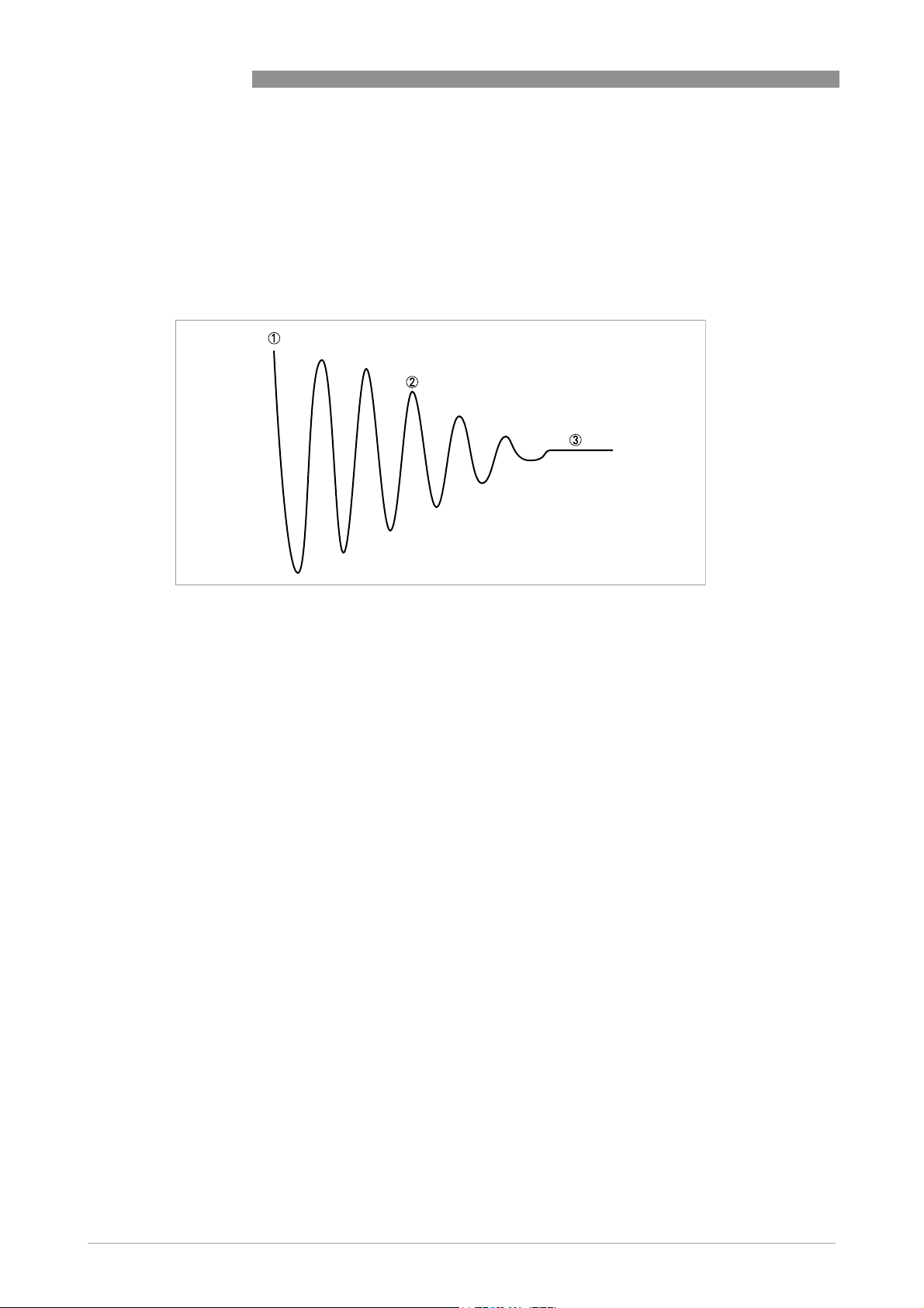
6
OPERATION
Pressure suppression (C1.1.7 & C1.1.8)
The pressure suppression eliminates any disruption in the measurement in the event of an
abrupt flow switch-off e.g. when valves are suddenly closed. In such cases, surges may occur in
the pipe and in the measuring device which could lead to over-vibration. The flow then "swings"
back and forth before a stable zero flow is established, as shown in the figure below. This effect
occurs mainly in high pressure applications.
MFC 400
Figure 6-6: Vibration behaviour during pressure suppression
1 Flow switched off
2 Sinusoidal vibration ("over-vibration")
3 Stable zero flow
The pressure suppression function eliminates this effect by activating a larger low flow cutoff
threshold for a programmable period of time. The pressure suppression is activated when the
flow falls below the standard low flow cutoff level for the first time (C1.1.6). For a programmable
period of time (C1.1.8), the pressure suppression threshold is added to the standard low flow
threshold (C1.1.7).
This parameter is only available if the device is switched to expert mode (C6.4.5).
Measurement of flow velocity
The signal converter can provide the flow velocity based on a pipe diameter which the operator
can freely program (C1.1.9). This value can either be the inner diameter of the measuring tube
(factory setting) or the inner diameter of the process pipe.
92
www.krohne.com 01/2021 - 4002075808 - MA MFC400 ER2.1 R08 en
Page 93
MFC 400
6.5.2 Density (C1.2.0 Density)
Density mode (C1.2.2 Density Mode)
There are 4 available operating modes for density that can be set here:
• Process:
The device measures and displays the current operating density of the product.
• Fixed:
The device displays a fixed density value. This value must be entered in menu C1.2.3.
• Referred:
The device calculates the density based on a set reference temperature.
• Standard:
The device calculates the standard density based on a set reference temperature and the
correction factors k
The following equation is used for the "Referred" mode:
The following equation is used for the "Referred" mode:
The following equation is used for the "Referred" mode:The following equation is used for the "Referred" mode:
= ρa + a (ta - tr)
ρ
r
...k2, so that a standard volume can be output.
0
OPERATION
6
ρ
= Density at reference temperature
r
ρ
= Current measured operating density at current operating temperature
a
a = Programmed temperature coefficient/density gradient
= Current measured operating temperature
t
a
t
= Reference temperature
r
The reference temperature must be entered in menu item C1.2.4. The density gradient is set in
C1.2.5.
Figure 6-7: Calculating the density gradient
1 Density
2 Temperature
www.krohne.com01/2021 - 4002075808 - MA MFC400 ER2.1 R08 en
93
Page 94

6
OPERATION
The following equation is used to calculate the density gradient:
The following equation is used to calculate the density gradient:
The following equation is used to calculate the density gradient:The following equation is used to calculate the density gradient:
a = (ρ
The value for the density gradient is generally positive as an increase in temperature usually
reduces the measured density (exception: water anomaly).
Calculating the standard density
Calculating the standard density
Calculating the standard densityCalculating the standard density
The measuring device can display a density which has been corrected in terms of the standard
temperature in accordance with API MPMS 11.1.
The corresponding reference temperature is entered in menu C1.2.4. The correction factors
...k2 are entered in menu C1.2.7...C1.2.9.
k
0
- ρC) / (TB - TA)
D
MFC 400
Type of product
Low limit ρ15High limit ρ15k
(according to API)
[kg/m3]
Crude oil 610.5 1075.0 613.9723 0 0
Gasoline 653.0 770.0 346.4228 0.4388 0
Transition area 770.5 787.5 2680.3206 0 -0.00336312
Jet group 788.0 838.5 594.5418 0 0
Fuel oil 839.0 1075.0 186.9696 0.4862 0
Free fill in 500.0 2000.0 0 0 0
Table 6-19: Example of standard factors
6.5.3 System control (C1.4.0 System Control)
The signal converter provides a system control function which allows to set the flow to 0 in case
of a programmable process conditions. The system control function can be enabled in menu
C1.4.1. The following menu items configure the condition and limits for activation of system
control:
This parameter is only available if the device is switched to expert mode (C6.4.5).
C1.4.2 Condition
Selecting the process measurement which activates the system control. Density and
temperature can be selected.
0
k
1
k
2
94
C1.4.3 Max. Temperature/Density & C1.4.4 Min. Temperature/Density
Setting the limit values to activate system control. Current measuring values outside of this
range activate this function.
www.krohne.com 01/2021 - 4002075808 - MA MFC400 ER2.1 R08 en
Page 95

MFC 400
6.5.4 Detection of 2 phase flow
Due to EGMTM (Entrained Gas Management) the device performs a stable measurement function
between 0…100% gas ratio. The device provides a signal which indicates two phase flow. This
signal can be used for signalling two phase flow according to NE 107 or for approximating the
amount of entrained gas. The signal depends on the amount, distribution and size of the
entrained gas and therefore any threshold has to be adapted on the application.
Screen Description and setting
B2.14.0 2 Phase Signal Display of actual value for two phase signal.
Table 6-20: Display of two phase signal
Screen Description and setting
C1.5.2 Diagnosis 1 Set "2 Phase Signal".
Table 6-21: Output of two phase signal via any I/O or measure page
OPERATION
6
Screen Description and setting
C1.5.1 2 Phase Threshold Set a value above 0 in order to activate the two phase signalling via
C6.6.3 Proc: 2 Phase Flow Select the status signal for two phase flow.
Table 6-22: Signalling of 2 phase flow
the device and process value status. In case of two phase flow the
status message "2 Phase Flow Detected" is generated.
www.krohne.com01/2021 - 4002075808 - MA MFC400 ER2.1 R08 en
95
Page 96

6
OPERATION
6.6 I/O configuration
6.6.1 Damp output signals
All digital and analogue outputs provide damping with a digital filter which allows to stabilise the
output. The damping can be individually set for each output by a time constant. However, keep in
mind that the degree of filtration affects the response time of the device in the event of rapid
changes.
The general behaviour of the damping value is:
• Small damping:
- Fast response times
- Fluctuating reading
• Large damping:
- Slow response time
- Stable reading
The damping corresponds to the elapsed time until 63% of the end value has been reached
according to a step function. The time until 90% of the end value is reached in case of a step
response is T90 = τ * 1.8 (τ = damping).
MFC 400
6.6.2 Suppress small flow rates
All digital and analogue outputs provide a low flow cutoff for flow measurements in order to
suppress small flow rates.
If the low flow cutoff has been activated, the respective output is set to zero when the flow is
below the low flow cutoff value entered. The value can be entered as a percentage of the upper
range value or in the case of a pulse output as a discrete flow value.
Two values must be entered. The first is for the operating point of the flow sensor and the second
is for hysteresis.
Condition: 1st value > 2nd value
Figure 6-8: Indication of low flow cutoff
1 Flow
2 Time
3 Currently indicated flow
4 Display set to zero
5 Currently indicated flow
6 Positive hysteresis
7 Operating point
8 Negative hysteresis
96
www.krohne.com 01/2021 - 4002075808 - MA MFC400 ER2.1 R08 en
Page 97

MFC 400
6.6.3 Polarity of measurement
All digital and analogue outputs provide a polarity setting which allows:
Polarity Function
Both Polarity function does not affect output values.
Positive Positive values passed to output, negative values set to 0.
Negative Absolute value of negative values passed to output, positive values set to 0.
Absolute Absolute value of input values.
Table 6-23: Description of polarities
INFORMATION!
For reverse flow detection at a current output set polarity to "Both" and select the lower and
upper flow range values for your application.
6.6.4 Current output
The current outputs of the signal converter have several operation modes which can be
configured by the current span and the alarm signal. The lower and upper range value is mapped
to the lower and upper endpoint as depicted in the following figure:
OPERATION
6
Figure 6-9: Operation modes of the current output
1 Output current
2 Measuring value
www.krohne.com01/2021 - 4002075808 - MA MFC400 ER2.1 R08 en
97
Page 98

6
OPERATION
MFC 400
Current
span
Lower limit
(Q
)
LL
Lower end
point (Q
LE
)
Upper end
point (Q
UE
)
Upper limit
(Q
)
UL
Low alarm High alarm
[mA]
4...20 3.8 4.0 20.0 20.5 3.5 21.5
0...20 1 0 0 20.0 20.0 0 2 21.5
Custom Custom values Custom values
Table 6-24: Limit values
1 Only available if HART is disabled or not available for respective current output
2 Low alarm signalling is not recommended for current span 0...20 mA
Reaching the lower or upper limit is signalled by the status "Out of Specification" but does not
set an alarm signal. All current outputs detect an open loop or output current errors due to
exceeded load values.
6.6.5 Alarm signalling via current outputs
Current outputs provide an alarm signalling via upper or lower failure current. The alarm signal
is set by default in case of device failure, i.e. if the status signal failure is set. If additional status
signals should be considered, the error condition can be changed:
Alarm condition Evaluated status signals
Failure Failure
Out of Spec Failure or Out of Spec
Table 6-25: Alarm conditions
6.6.6 Pulse output and batching applications
Pulse outputs of the signal converter are designed for minimum latency and suited for use with
pulse counters (mechanical, digital) or provers (e.g. small volume provers).
Select the maximum output frequency according to your counter.
Some custody transfer applications require dual phase pulse outputs. For this purpose pulse
outputs from two terminals can be paired. Terminal pairs A and B or D and B can be used.
In this case, the frequency is limited to a maximum of 5000 Hz.
In this case, perform the following settings:
• Configure pulse output terminal A or D
• Set "Output B" to phase shifted mode in menu C2.3.10 by choosing the base pulse output (A or
D). All functions for output B are set using output D or output A.
• Phase shift relative to output A: set phase shift (0°, 90° or 180°) in menu C2.2.10
Phase shift relative to output D: set phase shift (0°, 90° or 180°) in menu C2.4.10
98
www.krohne.com 01/2021 - 4002075808 - MA MFC400 ER2.1 R08 en
Page 99

MFC 400
6.7 Display configuration
6.7.1 Optical keys (C5.3.0 Optical Keys)
This function can deactivate the optical keys. In this case, the device may only be operated using
the push buttons. In the display, the switched off state of the optical keys is represented the
following symbol in the upper right corner:
Figure 6-10: Indication of optical keys in switched off state
OPERATION
6
6.7.2 Backlight (C5.4.0 Backlight)
The signal converter local display has a colour backlight which can be used to show the NE 107
status. In menu C5.4.0 its behaviour can be configured as described in the following table:
Backlight settings Description
Off Backlight always turned off.
White Backlight colour is always white.
Red - Failure Backlight colour is set to red in case of a device failure.
NE107 Color Backlight colour is set according to the NE 107 status of the device.
Table 6-26: Description of backlight settings
6.8 Configuration management (C6.3.0 Config. Management)
6.8.1 Load and save configuration (C6.3.1 Save Settings & C6.3.2 Load Settings)
The signal converter provides functions to store and restore sets of configurations (Backup 1 and
Backup 2). Using the functions in C6.3.2 the present configuration can be stored for later
restoration via C6.3.1.
For documentation purposes please note the checksum for the present configuration (B1.2.0
Change Log).
www.krohne.com01/2021 - 4002075808 - MA MFC400 ER2.1 R08 en
99
Page 100

6
OPERATION
6.8.2 Factory reset (C6.3.3 Factory Reset)
The signal converter configuration can be reset to factory configuration.
INFORMATION!
Be careful with this function because this process cannot be reverted.
6.8.3 Change log (B1.2.0 Change Log)
Any configuration change of the signal converter is logged within a change log (B1.2.0) with date
and time and a checksum of the signal converter configuration. The change log covers all device
parameters (incl. factory parameters) and provides 128 entries.
6.8.4 Locking of configuration
Access authentication
The signal converter has a multilevel access authentication concept which allows to protect the
entire configuration against unauthorised write accesses. The access authentication is disabled
by default, however can be enabled by setting an operator password that is not equal to 0000. In
case of an enabled access authentication, write accesses via any interface (local display, HART
OPTICHECK, …) can only be performed after authentication by entering the respective access
level password (refer to next table). Entering this password only unlocks the currently used
interface but no other interfaces.
MFC 400
®
,
Level Description Authentication
0 User / Free No authentication necessary.
1 Operator Operator password (C6.3.4 Set Operator Password) or no authentication
2 Service Service password.
Jumper Application
Specific Lock
Table 6-27: Available access levels
necessary if operator password not set (0000).
Remove jumper.
A lock of parameters and functions via access authentication is indicated as depicted in the
following figure:
Figure 6-11: Indication of access authentication
100
www.krohne.com 01/2021 - 4002075808 - MA MFC400 ER2.1 R08 en
 Loading...