

Page 1
Supplementary instructions
Supplementary instructions
MFC 400
MFC 400
MFC 400MFC 400
Supplementary instructions Supplementary instructions
Signal converter for mass flowmeters
Description of PROFIBUS interface
Description of PROFIBUS interface
Description of PROFIBUS interfaceDescription of PROFIBUS interface
PROFIBUS PA:
PROFIBUS PA:
PROFIBUS PA:PROFIBUS PA:
PROFIBUS device with MBP Physical Interface and PA Profile 3.02 (V1.0.3_ / 130603)
PROFIBUS DP:
PROFIBUS DP:
PROFIBUS DP:PROFIBUS DP:
PROFIBUS device with RS485 Physical Interface and PA Profile 3.02 (V1.0.3_ / 130603)
The documentation is only complete when used in combination with the relevant
documentation for the .
© KROHNE 06/2013 - 4002835301 - AD MFC 400 PROFIBUS R01 en
Page 2

CONTENTS
MFC 400
1 Safety instructions 4
1.1 Scope of the document..................................................................................................... 4
1.2 Scope of delivery............................................................................................................... 4
1.3 Special notes .................................................................................................................... 4
2 PROFIBUS DP 5
2.1 Software history ............................................................................................................... 5
2.2 System configuration of PROFIBUS DP network............................................................. 5
2.3 Electrical connection for DP signal converter................................................................. 6
2.4 Technical data................................................................................................................... 8
2.5 PROFIBUS PA Profile implementation ............................................................................ 9
2.6 GSD files ........................................................................................................................... 9
2.7 Ident. Number selector .................................................................................................. 10
2.8 Summary ........................................................................................................................ 13
2.9 Baud rate ........................................................................................................................ 14
3 PROFIBUS PA 15
3.1 Software history ............................................................................................................. 15
3.2 System configuration of PROFIBUS PA network ........................................................... 16
3.3 Electrical connection for PA signal converter ............................................................... 17
3.4 Technical data................................................................................................................. 18
3.5 PROFIBUS PA Profile implementation .......................................................................... 19
3.6 GSD files ......................................................................................................................... 19
3.7 Ident. Number selector .................................................................................................. 20
3.8 Summary ........................................................................................................................ 23
4 Commissioning / Operation 24
4.1 Configuration of cyclic data transfer.............................................................................. 24
4.2 Cyclic data....................................................................................................................... 24
4.2.1 Input data .............................................................................................................................. 24
4.2.2 Output data............................................................................................................................ 30
4.3 Diagnosis ........................................................................................................................ 31
4.3.1 Mapping of DIAGNOSIS_EXTENSION bits into DIAGNOSIS bits if "Condensed Status and Di-
agnosis" handling selected ............................................................................................................ 37
4.3.2 Mapping of DIAGNOSIS_EXTENSION bits into DIAGNOSIS bits if "Classic Status and Diagno-
sis" handling selected .................................................................................................................... 40
4.3.3 Variable "Event groups"........................................................................................................ 42
4.3.4 Filtering of "Single events"................................................................................................... 45
2
www.krohne.com 06/2013 - 4002835301 - AD MFC 400 PROFIBUS R01 en
Page 3

MFC 400
CONTENTS
5 Profibus settings 46
5.1 Menu A, Quick Setup ...................................................................................................... 46
5.2 Menu B, Test................................................................................................................... 46
5.3 Menu C, Setup................................................................................................................. 47
5.4 Menu D, Service.............................................................................................................. 51
5.5 Status messages and diagnostic information................................................................ 52
6 Notes 54
www.krohne.com06/2013 - 4002835301 - AD MFC 400 PROFIBUS R01 en
3
Page 4

1 SAFETY INSTRUCTIONS
1.1 Scope of the document
These instructions are supplementary to the signal converter Handbook. For all other data, use
the relevant chapters of the Handbook. If you do not have this document, please contact the
nearest office or download them from the manufacturer's internet site.
INFORMATION!
The information in this chapter only contains the data applicable to PROFIBUS communication.
The technical data in the Handbook shall be valid in its current version, provided that it is not
rendered invalid or replaced by this supplement.
1.2 Scope of delivery
The information in this chapter only contains the data applicable to PROFIBUS communication.
The technical data in the Handbook shall be valid in its current version, provided that it is not
rendered invalid or replaced by this supplement.
A device for PROFIBUS communication is supplied with:
MFC 400
• Supplementary instructions for PROFIBUS communication
• PROFIBUS device data files (GSD) which can be also downloaded from the manufacturer's
internet site
1.3 Special notes
Don't switch off (power off) the signal converter immediately after manual change of parameter
values:
• Please wait approx. 10 seconds before you switch off the signal converter after you have done
both a parameter download via PROFIBUS or a manual change of a parameter value via the
local display.
CAUTION!
Please wait approx. 15 seconds before you switch off the signal converter after you have carried
out a "Factory Reset" (PROFIBUS "Coldstart") via PROFIBUS or local display.
"Deactivation of the Service Parameter Lock" of the signal converter via PROFIBUS:
• After writing down the service password (via PROFIBUS) the "Deactivation of the Service
Parameter Lock" will last at least 20 minutes if the internal password timer of the signal
converter won't be retriggered by writing this password again. The "Deactivation of the
Service Parameter Lock" will be terminated at once by a PROFIBUS Coldstart / Warmstart or
if the internal password timer of the signal converter elapsed.
4
www.krohne.com 06/2013 - 4002835301 - AD MFC 400 PROFIBUS R01 en
Page 5

MFC 400
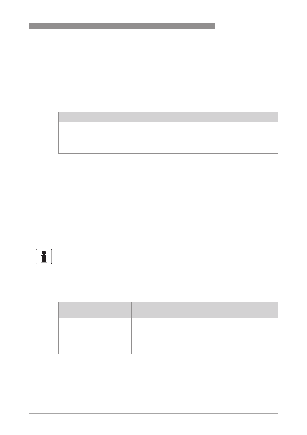
2.1 Software history
Issued Signal converter Application program System integration
PROFIBUS DP 2
Mth./
Hardware Firmware Hardware Software Driver Version Model name
year
06/13 Signal
converter
with
RS485
interface +
PA Profile
3.02
V1.0.3_ /
130603
Simatic
PCS7
other SPS
of other
manufact.
Laptop / PC PDM
HW Config
other
Software of
other SPS
manufact.
(≥ 6.0 SP5)DD(Ident.-No.)
Pactware DTM ≥ - -
GSD
manuf.
specific
GSD
profile
specific
The PROFIBUS DP device has a RS485 interface to connect the device to a PROFIBUS DP
network.
The software supports the PROFIBUS PA Profile 3.02. Both, cyclic services towards a control
system (e.g. PLC) as well as acyclic services for operating with engineering tools (e.g. DD/DTM
based tools) are supported.
The PROFIBUS station address can be set via PROFIBUS services or via the device display.
2.2 System configuration of PROFIBUS DP network
KR014512.GSD MFC400
(RS485)
Rev.1
PA039742.GSD Flow, dens,
temp with
3AI, 1TOT
(PhyL 0)
- -
The following diagram shows a typical network configuration with PROFIBUS devices with RS485
interface in a non-hazardous environment. The PROFIBUS devices with RS485 interface do not
need any segment coupler. They are connected directly to the PROFIBUS DP network.
Figure 2-1: PROFIBUS DP network
1 SPS
2 PROFIBUS DP with max. 12 Mbit/s
3 Signal converter
4 Other devices with PROFIBUS RS485 interface
www.krohne.com06/2013 - 4002835301 - AD MFC 400 PROFIBUS R01 en
5
Page 6
2 PROFIBUS DP
2.3 Electrical connection for DP signal converter
INFORMATION!
For a detailed description of the electrical connections please refer to the standard signal
converter handbook.
Signal converter terminals B B- C C- D D-
PROFIBUS designation T +B -A -T +B -A
1 2 3 4 5 6
1 Termination positive
2 TxD+/RxD+ second connection
3 TxD-/RxD- second connection
4 Termination negative
5 TxD+/RxD+ first connection
6 TxD-/RxD- first connection
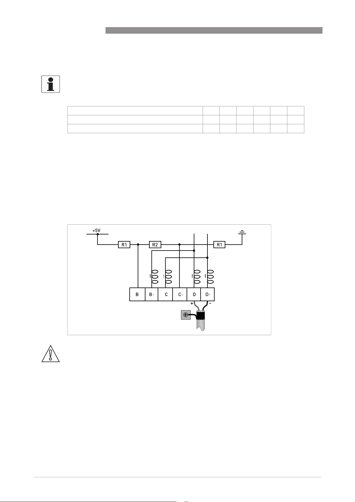
MFC 400
External connection with spur
CAUTION!
Spurs are not allowed at high data rates!
I = 110 nH
R1 = 390 Ω
R2 = 220 Ω
6
www.krohne.com 06/2013 - 4002835301 - AD MFC 400 PROFIBUS R01 en
Page 7
MFC 400
PROFIBUS DP 2
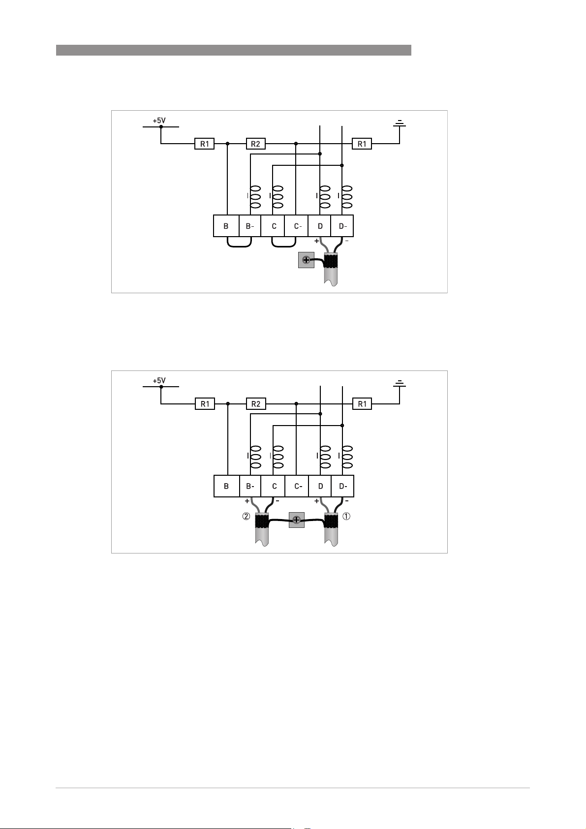
External connection at last device with active internal bus termination
I = 110 nH
R1 = 390 Ω
R2 = 220 Ω
External connection to a trunk
1 e.g. incoming data lines
2 e.g. outgoing data lines
I = 110 nH
R1 = 390 Ω
R2 = 220 Ω
www.krohne.com06/2013 - 4002835301 - AD MFC 400 PROFIBUS R01 en
7
Page 8

2 PROFIBUS DP
2.4 Technical data
Hardware
Type PROFIBUS RS485 interface according to IEC 61158-2
Connection Dependent of polarity; please note at electrical connection!
Software
GSD GSD file on CD-ROM or from internet site
Device profile PROFIBUS PA Profile 3.02; conformance class B, compact
Address range 0…126 (default 126)
Local control Local display and operator interface at device
SAPs 2 x MS1 SAPs – acyclic interface to PLC
Function blocks 1 x TB = Transducer Block: contains the parameters and functions
MFC 400
Supported GSD:
• KRO14512.GSD
• PA039742.GSD
0…125 via PROFIBUS service set_slave_add
0…126 via local display
126 via factory_reset = 2712
3 x MS2 SAPs – the number of MS2 Service Access Points is typically
equal to the maximum number of master class 2 tools
defined in PA Profile 3.02
1 x PB = Physical Block: contains the parameters defined in PA
Profile 3.02
8 x AI = Analog Input Blocks: contains the parameters defined in PA
Profile 3.02
3 x TOT = Totalizer Function Blocks: contains the parameters defined
in PA Profile 3.02
8
www.krohne.com 06/2013 - 4002835301 - AD MFC 400 PROFIBUS R01 en
Page 9

MFC 400
2.5 PROFIBUS PA Profile implementation
The PROFIBUS PA Profile 3.02 defines standardized parameters and functions for PROFIBUS
devices used for process control. It describes a PROFIBUS device as a function block application,
i.e. parameters and functions are grouped into different blocks. In the MFC 400 PROFIBUS
device the following blocks are implemented:
Block Usage
1 Physical Block (PB) contains identification and diagnosis parameters of the device
1 Flow Transducer Block
(TB)
8 Analog Input Function Block
(AI-FB)
3 Totalizer Function Blocks
(TOT-FB)
The Analog Input Function Block and the Totalizer Function Blocks provide the data interface
towards a process control system (e.g. a PLC); i.e. their input/output data can be read/written by
the control system. In a PROFIBUS network this is done via cyclic communication services.
contains parameters and functions to control the flow measurement
contains parameters and functions to control the measuring output;
provides the measuring value(s)
contains parameters and functions to control/provide the counter
value(s)
PROFIBUS DP 2
From the PROFIBUS point of view the MFC 400 device is designed as a compact device with 11
slots. While the Analog Input function blocks are assigned to slot 1, 2, 3, 7, 8, 9, 10 and 11 the
Totalizer Function Blocks are assigned to slot 4, 5 and 6. This assignment is fixed and cannot be
modified by the user. Nevertheless during network configuration the user can choose which
function block data shall be transferred between the PROFIBUS master and the PROFIBUS
device.
2.6 GSD files
The GSD file contains information that will be needed for configuration of the PROFIBUS DP
communication network. Supplementary files (e.g. ___.bmp and ___.dib) contain icons which will
represent the PROFIBUS devices in the view of the bus configuration system/master system. The
files must be loaded into the configuration program before. Follow the instructions in the
manual of the host supplier when installing GSD file and supplementary files.
A PROFIBUS GSD ZIP file (e.g. GSD-4002171502.zip) including both all GSD files of all KROHNE
devices with PROFIBUS PA interface and all additional data files mentioned above are available
at the KROHNE download page (e.g. http://www.krohne.com/html/dlc/GSD-4002171502.zip).
INFORMATION!
If it is supported by the host configuration tool the device entry for the MFC400 PROFIBUS device
will be located within the slave family "PROFIBUS PA".
www.krohne.com06/2013 - 4002835301 - AD MFC 400 PROFIBUS R01 en
9
Page 10

2 PROFIBUS DP
2.7 Ident. Number selector
Within a PROFIBUS network the type of a PROFIBUS slave is identified by its Ident. Number
which is unique for this slave type. The PROFIBUS DP device supports two different Ident.
Numbers. Therefore it can be installed for different use cases. When the Ident. Number is
changed the behaviour of the device concerning the cyclic data transfer is changed; i.e. the
maximum number of transferred measuring values and/or the length and content of the
diagnosis information will be different. The user can select the required Ident. Number by an
engineering tool (e.g. DD/DTM - parameter IDENT_NUMBER_SELECTOR slot 0; index 40) or via
the MFC 400 device display menu (menu item "Identification No.", C6.8.7).
The following settings are supported:
• Automatic adaptation mode (factory setting)
• Manufacturer specific Ident. Number (4512 hex)
• Profile specific Ident. Number (9742 hex)
Automatic adaptation mode (factory setting)
If the parameter IDENT_NUMBER_SELECTOR is set to this mode the device will select its
operation mode during start-up of the cyclic data transfer according to the used GSD file. The
active Ident. Number is set to one of the settings described below. If the
IDENT_NUMBER_SELECTOR is changed to this mode the current Ident. Number is not changed
until the cyclic data transfer is (re-)started.
MFC 400
INFORMATION!
Depending on the components in the PROFIBUS network the automatic adaptation might fail. In
this case the active Ident. Number has to be selected by the user via an engineering tool or via
the device display menu. The parameter IDENT_NUMBER_SELECTOR has to be set to a fixed
Ident. Number.
10
www.krohne.com 06/2013 - 4002835301 - AD MFC 400 PROFIBUS R01 en
Page 11

MFC 400
PROFIBUS DP 2
Manufacturer specific Ident. Number (4512 hex)
This setting provides complete functionality of the PROFIBUS DP device. All function Blocks are
available for cyclic data transfer. Device specific diagnosis information is transferred in addition
to the Profile diagnosis.
Cyclic layout:
Slot Description Function Block types Default unit
1 Mass Flow AI-FB kg/s
2 Density AI-FB kg/l
3 Temperature AI-FB K
4 Mass Totaliser Totaliser-FB kg
5 Volume Totaliser Totaliser-FB
6 Mass Totaliser Totaliser-FB kg
7 Volume Flow AI-FB
8 Concentration 1 AI-FB %
9 Concentration 2 AI-FB %
10 Concentration Mass Flow 1 AI-FB kg/s
11 Concentration Mass Flow 2 AI-FB kg/s
3
m
m3/h
• AI: Analog Input Function Block
• FB: Function Block
There are separate settings to select the units for local display and PROFIBUS. Modifications of
the units of the display will have no effect on the data transferred via PROFIBUS.
A master class 2 tool is required to modify the units for PROFIBUS transfer.
Valid GSD Modules:
AI-FB Empty Module
Totaliser-FB Empty Module
AI: Out
TOT (Id.F.): Total
TOT (Id.F.): SetTot + Total
TOT (Id.F.): ModeTot + Total
TOT (Id.F.): SetTot+ModeTot+Total
TOT (Id.F.): SetTot
TOT (Id.F.): ModeTot
TOT (Id.F.): SetTot + ModeTot
GSD File required:
GSD file KRO14512.GSD
the PROFIBUS DP device. All function blocks are available for cyclic data transfer.
KRO14512.GSD is required in this mode. This GSD file provides complete functionality of
KRO14512.GSDKRO14512.GSD
INFORMATION!
If another GSD file is used in the PROFIBUS master system the cyclic data transfer cannot be
established in this setting.
www.krohne.com06/2013 - 4002835301 - AD MFC 400 PROFIBUS R01 en
11
Page 12

2 PROFIBUS DP
INFORMATION!
During network configuration the user has to define which function block outputs of the signal
converter should be transferred cyclically to the master. This is performed by a bus
configuration tool (e.g. "HW- Config" for PC-S7 from Siemens). This tool offers specific functions
as follows:
1. It is possible to configure an "Empty" block (the code of an "Empty" block is defined as 0x00) on
each block number. This implies: no data are transmitted in the cyclic data telegram for this
block.
2. There is NO "Totaliser (TOT)" function block allowed on block position 1, 2, 3, 7, 8, 9, 10 and 11!
On these positions, only an "Analog Input (AI)" function block or an "Empty" block is allowed!
(Note: All codes supported by "Analog Input (AI)" - and "Totaliser (TOT)"
be found in the corresponding GSD files.)
3. There is NO "Analog Input (AI)" function block allowed on block position 4, 5 and 6! On these
positions, only a "Totaliser (TOT)" function block or an "Empty" block is allowed!
4. There is a choice of 7 different totaliser functions, which can be allocated to the blocks 4, 5
and/or 6.
MFC 400
–
function blocks will
12
www.krohne.com 06/2013 - 4002835301 - AD MFC 400 PROFIBUS R01 en
Page 13
MFC 400
PROFIBUS DP 2
Profile specific Ident. Number (9742 hex)
Functionality is reduced to the requirements which are mandatory in the PA Profile; e.g. 3 x AIFB and 1 x TOT-FB are available for cyclic data transfer only. Device specific diagnosis
information is not available via cyclic PROFIBUS services. Nevertheless this behaviour will
improve interchangeability between devices of different vendors because only functions are
available which are provided by all PROFIBUS PA variable area flowmeters. Exchange is possible
without modifying the configuration of the control system.
Cyclic layout:
Slot Description Function Block type Default unit
1 Mass Flow AI-FB kg/s
2 Density AI-FB kg/l
3 Temperature AI-FB K
4 Mass Totaliser Totaliser-FB kg
Valid GSD Modules:
AI-FB EMPTY_MODULE
AI
Totaliser-FB EMPTY_MODULE
TOTAL
SETTOT_TOTAL
SETTOT_MODETOT_TOTAL
GSD File required:
GSD file PA039742.GSD
Take care that "Condensed Status and Diagnosis" is not supported by this file.
INFORMATION!
If another GSD file is used in the PROFIBUS master system the cyclic data transfer cannot be
established in this setting.
2.8 Summary
The following table shows a summary of the supported combinations of the PROFIBUS
device with RS485 Physical Interface and PA Profile 3.02:
Ident. Number Selector Ident.
Automatic adaptation mode 4512 KR014512.GSD Classic / Condensed
Manufacturer specific Ident.
Number
Profile specific Ident. Number 9742 PA039742.GSD 1 Classic
1 This file is p rovided by P ROFIBUS Interna tional (www .profibus.com) . Take care t hat "Condense d Status and Diagnosis"
is not supported by this file.
PA039742.GSD is required in this mode. This file is provided by PROFIBUS International.
PA039742.GSDPA039742.GSD
GSD File Status
Number
9742 PA039742.GSD 1 Classic
4512 KR014512.GSD Classic / Condensed
www.krohne.com06/2013 - 4002835301 - AD MFC 400 PROFIBUS R01 en
13
Page 14

2 PROFIBUS DP
2.9 Baud rate
Supported baud rates are listed in the GSD file (see below). After power-on or PROFIBUS
timeout a baud rate search is active to detect the current transfer speed on the bus. It is not
necessary to set the baud rate manually.
If the data transmission rate is changed during operation the baud rate search will not be started
by the device. A new power-up or a manual interruption of the PROFIBUS communication is
required to activate the baud rate search in this case.
MFC 400
14
www.krohne.com 06/2013 - 4002835301 - AD MFC 400 PROFIBUS R01 en
Page 15

MFC 400
3.1 Software history
Issued Signal converter Application program System integration
PROFIBUS PA 3
Mth./
Hardware Firmware Hardware Software Driver Version Model name
year
06/13 Signal
converter
with MBP
interface +
PA Profile
3.02
V1.0.3_ /
130603
Simatic
PCS7
other SPS
of other
manufact.
Laptop / PC PDM
HW Config
other
Software of
other SPS
manufact.
(≥ 6.0 SP5)DD(Ident.-No.)
Pactware DTM ≥ - -
GSD
manuf.
specific for
stand.
DP/PA
segment
coupler
GSD
profile
specific
KR014513.GSD MFC400 (MBP)
Rev.1
PA139742.GSD Flow, dens,
temp with
3AI, 1TOT
(PhyL 1)
- -
www.krohne.com06/2013 - 4002835301 - AD MFC 400 PROFIBUS R01 en
15
Page 16

3 PROFIBUS PA
3.2 System configuration of PROFIBUS PA network
The following diagram shows a typical instrumentation with PROFIBUS PA devices with MBP
interface in hazardous and non-hazardous locations, including connections of conventional
devices (e.g. with 4...20 mA signals) in a PROFIBUS network.
As a rule, the PROFIBUS PA segment is connected to a segment coupler which, among other
things, carries out the conversion to the PROFIBUS DP bus line. It should be mentioned that the
segment coupler is normally set to a fixed baud rate on the DP side.
MFC 400
Figure 3-1: PROFIBUS PA network
1 Control system (PLC); class 1 master
2 Engineering or operation control tool; class 2 master
3 PROFIBUS DP network with max. 12 Mbit/s
4 PROFIBUS PA segment coupler DP / PA
5 Device with PROFIBUS PA interface, 31.25 kbit/s
6 HART
7 More devices with 4…20 mA
8 Analogue I/O module
®
device
16
www.krohne.com 06/2013 - 4002835301 - AD MFC 400 PROFIBUS R01 en
Page 17
MFC 400
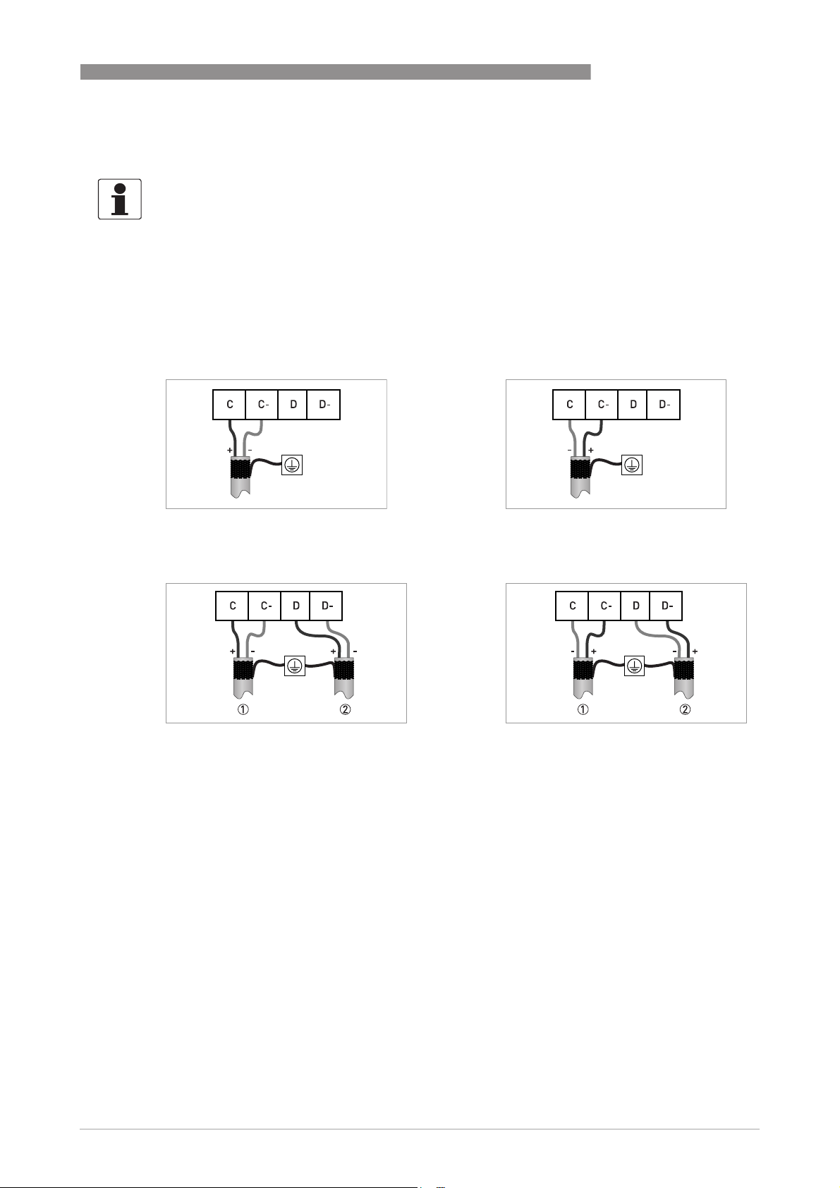
3.3 Electrical connection for PA signal converter
INFORMATION!
The wiring between the device and the PROFIBUS PA bus cable is independant of polarity.
The signal converter PROFIBUS PA interface will operate only if the additional power supply for
the device is connected/available.
For a detailed description of the electrical connections please refer to the standard signal
converter handbook. Refer also to the PROFIBUS PA user and installation guideline (Version 2.2,
February 2003 PNO order no. 2.092).
Connection to a spur
or
PROFIBUS PA 3
Connection to a trunk
1 e.g. incoming data lines
2 e.g. outgoing data lines
or
www.krohne.com06/2013 - 4002835301 - AD MFC 400 PROFIBUS R01 en
17
Page 18

3 PROFIBUS PA
3.4 Technical data
Hardware
Type PROFIBUS MBP interface according to IEC 61158-2 with
Connection Independent of polarity at electrical connection
Base current 10.5 mA
FDE Yes, separate fault disconnection electronics provided (FDE = Fault
Fault current 6 mA (fault current = max. continuous current – base current)
Starting current <12 mA
Ex approval Ex ia IIC or Ex ib IIC/IIB, FISCO Device
Software
GSD GSD file on CD-ROM or from internet site
Device profile PROFIBUS PA Profile 3.02; conformance class B, compact
Address range 0…126 (default 126)
Local control Local display and operator interface at device
SAPs 2 x MS1 SAPs – acyclic interface to PLC
Function blocks 1 x TB = Transducer Block: contains the parameters and functions
MFC 400
31.25 kbits/s; voltage mode
[MBP = Manchester Coded Bus Powered]
Disconnection Electronics)
For detailed information refer to standard product documentation.
Supported GSD:
• KRO14513.GSD
• PA139742.GSD
0…125 via PROFIBUS service set_slave_add
0…126 via local display
126 via factory_reset = 2712
3 x MS2 SAPs – the number of MS2 Service Access Points is typically
equal to the maximum number of master class 2 tools
defined in PA Profile 3.02
1 x PB = Physical Block: contains the parameters defined in PA
Profile 3.02
8 x AI = Analog Input Blocks: contains the parameters defined in PA
Profile 3.02
3 x TOT = Totalizer Function Blocks: contains the parameters defined
in PA Profile 3.02
18
www.krohne.com 06/2013 - 4002835301 - AD MFC 400 PROFIBUS R01 en
Page 19

MFC 400
3.5 PROFIBUS PA Profile implementation
The PROFIBUS PA Profile 3.02 defines standardized parameters and functions for PROFIBUS
devices used for process control. It describes a PROFIBUS device as a function block application,
i.e. parameters and functions are grouped into different blocks. In the MFC 400 PROFIBUS
device the following blocks are implemented:
Block Usage
1 Physical Block (PB) contains identification and diagnosis parameters of the device
1 Flow Transducer Block
(TB)
8 Analog Input Function Block
(AI-FB)
3 Totalizer Function Blocks
(TOT-FB)
The Analog Input Function Block and the Totalizer Function Blocks provide the data interface
towards a process control system (e.g. a PLC); i.e. their input/output data can be read/written by
the control system. In a PROFIBUS network this is done via cyclic communication services.
contains parameters and functions to control the flow measurement
contains parameters and functions to control the measuring output;
provides the measuring value(s)
contains parameters and functions to control/provide the counter
value(s)
PROFIBUS PA 3
From the PROFIBUS point of view the MFC 400 device is designed as a compact device with 11
slots. While the Analog Input function blocks are assigned to slot 1, 2, 3, 7, 8, 9, 10 and 11 the
Totalizer Function Blocks are assigned to slot 4, 5 and 6. This assignment is fixed and cannot be
modified by the user. Nevertheless during network configuration the user can choose which
function block data shall be transferred between the PROFIBUS master and the PROFIBUS
device.
3.6 GSD files
The GSD file contains information that will be needed for configuration of the PROFIBUS DP
communication network. Supplementary files (e.g. ___.bmp and ___.dib) contain icons which will
represent the PROFIBUS devices in the view of the bus configuration system/master system. The
files must be loaded into the configuration program before. Follow the instructions in the
manual of the host supplier when installing GSD file and supplementary files.
A PROFIBUS GSD ZIP file (e.g. GSD-4002171502.zip) including both all GSD files of all KROHNE
devices with PROFIBUS PA interface and all additional data files mentioned above are available
at the KROHNE download page (e.g. http://www.krohne.com/html/dlc/GSD-4002171502.zip).
INFORMATION!
If it is supported by the host configuration tool the device entry for the MFC400 PROFIBUS device
will be located within the slave family "PROFIBUS PA".
www.krohne.com06/2013 - 4002835301 - AD MFC 400 PROFIBUS R01 en
19
Page 20

3 PROFIBUS PA
3.7 Ident. Number selector
Within a PROFIBUS network the type of a PROFIBUS slave is identified by its Ident. Number
which is unique for this slave type. The PROFIBUS PA device supports two different Ident.
Numbers. Therefore it can be installed for different use cases. When the Ident. Number is
changed the behaviour of the device concerning the cyclic data transfer is changed; i.e. the
maximum number of transferred measuring values and/or the length and content of the
diagnosis information will be different. The user can select the required Ident. Number by an
engineering tool (e.g. DD/DTM - parameter IDENT_NUMBER_SELECTOR slot 0; index 40) or via
the MFC 400 device display menu (menu item "Identification No.", C6.8.7).
The following settings are supported:
• Automatic adaptation mode (factory setting)
• Manufacturer specific Ident. Number (4513 hex)
• Profile specific Ident. Number (9742 hex)
Automatic adaptation mode (factory setting)
If the parameter IDENT_NUMBER_SELECTOR is set to this mode the device will select its
operation mode during start-up of the cyclic data transfer according to the used GSD file. The
active Ident. Number is set to one of the settings described below. If the
IDENT_NUMBER_SELECTOR is changed to this mode the current Ident. Number is not changed
until the cyclic data transfer is (re-)started.
MFC 400
INFORMATION!
Depending on the components in the PROFIBUS network the automatic adaptation might fail. In
this case the active Ident. Number has to be selected by the user via an engineering tool or via
the device display menu. The parameter IDENT_NUMBER_SELECTOR has to be set to a fixed
Ident. Number.
20
www.krohne.com 06/2013 - 4002835301 - AD MFC 400 PROFIBUS R01 en
Page 21

MFC 400
PROFIBUS PA 3
Manufacturer specific Ident. Number (4513 hex)
This setting provides complete functionality of the PROFIBUS PA device. All function Blocks are
available for cyclic data transfer. Device specific diagnosis information is transferred in addition
to the Profile diagnosis.
Cyclic layout:
Slot Description Function Block types Default unit
1 Mass Flow AI-FB kg/s
2 Density AI-FB kg/l
3 Temperature AI-FB K
4 Mass Totaliser Totaliser-FB kg
5 Volume Totaliser Totaliser-FB
6 Mass Totaliser Totaliser-FB kg
7 Volume Flow AI-FB
8 Concentration 1 AI-FB %
9 Concentration 2 AI-FB %
10 Concentration Mass Flow 1 AI-FB kg/s
11 Concentration Mass Flow 2 AI-FB kg/s
3
m
m3/h
• AI: Analog Input Function Block
• FB: Function Block
There are separate settings to select the units for local display and PROFIBUS. Modifications of
the units of the display will have no effect on the data transferred via PROFIBUS.
A master class 2 tool is required to modify the units for PROFIBUS transfer.
Valid GSD Modules:
AI-FB Empty Module
Totaliser-FB Empty Module
AI: Out
TOT (Id.F.): Total
TOT (Id.F.): SetTot + Total
TOT (Id.F.): ModeTot + Total
TOT (Id.F.): SetTot+ModeTot+Total
TOT (Id.F.): SetTot
TOT (Id.F.): ModeTot
TOT (Id.F.): SetTot + ModeTot
GSD File required:
GSD file KRO14513.GSD
the PROFIBUS PA device. All function blocks are available for cyclic data transfer.
KRO14513.GSD is required in this mode. This GSD file provides complete functionality of
KRO14513.GSDKRO14513.GSD
INFORMATION!
If another GSD file is used in the PROFIBUS master system the cyclic data transfer cannot be
established in this setting.
www.krohne.com06/2013 - 4002835301 - AD MFC 400 PROFIBUS R01 en
21
Page 22

3 PROFIBUS PA
INFORMATION!
During network configuration the user has to define which function block outputs of the signal
converter should be transferred cyclically to the master. This is performed by a bus
configuration tool (e.g. "HW- Config" for PC-S7 from Siemens). This tool offers specific functions
as follows:
1. It is possible to configure an "Empty" block (the code of an "Empty" block is defined as 0x00) on
each block number. This implies: no data are transmitted in the cyclic data telegram for this
block.
2. There is NO "Totaliser (TOT)" function block allowed on block position 1, 2, 3, 7, 8, 9, 10 and 11!
On these positions, only an "Analog Input (AI)" function block or an "Empty" block is allowed!
(Note: All codes supported by "Analog Input (AI)" - and "Totaliser (TOT)"
be found in the corresponding GSD files.)
3. There is NO "Analog Input (AI)" function block allowed on block position 4, 5 and 6! On these
positions, only a "Totaliser (TOT)" function block or an "Empty" block is allowed!
4. There is a choice of 7 different totaliser functions, which can be allocated to the blocks 4, 5
and/or 6.
Profile specific Ident. Number (9742 hex)
Functionality is reduced to the requirements which are mandatory in the PA Profile; e.g. 3 x AIFB and 1 x TOT-FB are available for cyclic data transfer only. Device specific diagnosis
information is not available via cyclic PROFIBUS services. Nevertheless this behaviour will
improve interchangeability between devices of different vendors because only functions are
available which are provided by all PROFIBUS PA variable area flowmeters. Exchange is possible
without modifying the configuration of the control system.
MFC 400
–
function blocks will
Cyclic layout:
Slot Description Function Block type Default unit
1 Mass Flow AI-FB kg/s
2 Density AI-FB kg/l
3 Temperature AI-FB K
4 Mass Totaliser Totaliser-FB kg
Valid GSD Modules:
AI-FB EMPTY_MODULE
AI
Totaliser-FB EMPTY_MODULE
TOTAL
SETTOT_TOTAL
SETTOT_MODETOT_TOTAL
GSD File required:
GSD file PA139742.GSD
Take care that "Condensed Status and Diagnosis" is not supported by this file.
PA139742.GSD is required in this mode. This file is provided by PROFIBUS International.
PA139742.GSDPA139742.GSD
INFORMATION!
If another GSD file is used in the PROFIBUS master system the cyclic data transfer cannot be
established in this setting.
22
www.krohne.com 06/2013 - 4002835301 - AD MFC 400 PROFIBUS R01 en
Page 23

MFC 400
3.8 Summary
The following table shows a summary of the supported combinations of the PROFIBUS
device with MBP Physical Interface and PA Profile 3.02:
PROFIBUS PA 3
Ident. Number Selector Ident.
GSD File Status
Number
Automatic adaptation mode 4513 KR014513.GSD Classic / Condensed
9742 PA139742.GSD 1 Classic
Manufacturer specific Ident.
Number
Profile specific Ident. Number 9742 PA139742.GSD 1 Classic
1 This file is p rovided by P ROFIBUS Interna tional (www .profibus.com) . Take care t hat "Condense d Status and Diagnosis"
is not supported by this file.
4513 KR014513.GSD Classic / Condensed
www.krohne.com06/2013 - 4002835301 - AD MFC 400 PROFIBUS R01 en
23
Page 24

4 COMMISSIONING / OPERATION
4.1 Configuration of cyclic data transfer
During network configuration the user has to select which function block input/output data shall
be transferred between the PROFIBUS master and the PROFIBUS slave. Network configuration
will be done using one of the GSD files described before. During configuration a functional
module - describing a valid configuration of a single function block and defined in the GSD file
selected - has to be assigned to each slot of the device in order to select which data has to be
transferred for the corresponding function blocks.
The cyclic layout (have a look at chapter "Ident. Number selector") shows which type of
functional module is valid for each slot.
The order of transmission of the data always remains the same. If an "Empty Module" is
assigned to a slot no data will be sent for the corresponding function block and all function block
data following this empty module will move up one position.
4.2 Cyclic data
In a PROFIBUS network cyclic data is described from the point of view of the master. Therefore
input data is transferred from the slave to the master while output data is transferred from the
master to the slave.
MFC 400
4.2.1 Input data
Input data is transferred from the PROFIBUS device to the master for the measuring value and
the totalizer values. The format is the same for both. If input data transfer is configured 5 bytes
are transferred for the corresponding slot:
• 4 byte float value (Float Format according to IEEE Standard 754 Short Real Number)
• 1 byte status value
Float value
Float value
Float valueFloat value
The following example describes the format of the float value according to IEEE Standard 754
Short Real Number:
Float format
Byte n Byte n+1
Bit7 Bit6 Bit7 Bit6
VZ
Byte n+2 Byte n+3
Bit7 Bit7
-82-9
2
Mantissa Mantissa
7
6
5
4
3
2
1
0
2
2
2
2
2
2
2
2
Exponent Mantissa
-102-112-122-132-142-152-162-172-182-192-202-212-222-23
2
-12-22-32-4
2
-52-62-7
2
24
Example (binary): 40 F0 00 00 (hex) = 0100 0000 1111 0000 0000 0000 0000 0000
www.krohne.com 06/2013 - 4002835301 - AD MFC 400 PROFIBUS R01 en
Page 25

MFC 400
COMMISSIONING / OPERATION 4
Formula:
Formula:
Formula:Formula:
VZ
(Exponent – 127)
0
* 2
* 2
(129 – 127)
value = (-1)
value = (-1)
value = 1 * 4 * (1 + 0.5 + 0.25 + 0.125)
value = 7.5
Status value
Status value
Status valueStatus value
The PROFIBUS device supports the PROFIBUS-PA Profile Version 3.02. In this Profile the
Condensed Status and Diagnosis has replaced by default the Classic Status and Diagnosis of the
PROFIBUS-PA Profile Version 3.0. The Condensed Status and Diagnosis has been created to
make diagnostic events more obvious and to allow predictive and preventive maintenance.
Nevertheless Classic Status and Diagnosis is still available for this device. It is implemented for
backwards compatibility to "older" devices or PLC systems which do not support Condensed
Status and Diagnosis.
The device may be switched between "Condensed Status and Diagnosis" and "Classic Status and
Diagnosis"
• automatically during start-up of the cyclic data transfer by setting the parameter PRM_COND
within the Set_Prm service data.
• using an engineering tool (e.g. DD/DTM) to write the parameter COND_STATUS_DIAG (slot 0,
index 43).
• using the device display menu (menu item "Condensed Status", C6.8.8)
* (1 + Mantissa)
* (1 + 2-1 + 2-2 + 2-3)
Coding for the first two parameters is:
• 0: Classic Status
• 1: Condensed Status (factory setting)
Coding for the third selection is:
• OFF: Classic Status
• ON: Condensed Status (factory setting)
INFORMATION!
The parameter COND_STATUS_DIAG cannot be modified directly if cyclic data transfer is active.
Nevertheless it is reset to the factory setting if a reset to default data is requested by an
engineering tool.
www.krohne.com06/2013 - 4002835301 - AD MFC 400 PROFIBUS R01 en
25
Page 26

4 COMMISSIONING / OPERATION
The coding of the status value depends on the active status and diagnosis mode. It is described in
the following tables.
Condensed Status
Condensed Status
Condensed StatusCondensed Status
The Condensed Status codes have been defined to allow easier decoding of the information
provided by the PROFIBUS devices. The coding is shown in the following table:
Quality Quality substatus Limits
Gr Gr QS QS QS QS Qu Qu
7
6
5
4
3
2
2
2
2
2
2
0 0 = bad
0 1 = uncertain
1 0 = good (Non Cascade)
1 1 = good (Cascade) - not supported
Status = bad
1
2
2
MFC 400
0
2
Quality Quality substatus Limits
Gr Gr QS QS QS QS Qu Qu
7
6
5
4
3
2
1
2
2
2
2
2
2
0
2
2
0 0 0 0 0 0 0 0 = non-specific (not provided by the device)
0 0 1 0 0 0 1 1 = passivated (diagnostic alerts inhibited)
0 0 1 0 0 1 x x = maintenance alarm, more diagnosis available
0 0 1 0 1 0 x x = process related, no maintenance
0 0 1 1 1 1 x x = function check / local override; value not usable
Status = uncertain
Quality Quality substatus Limits
Gr Gr QS QS QS QS Qu Qu
7
6
5
4
3
2
1
2
2
2
2
2
2
0 1 0 0 1 0 x x = substitute set
0 1 0 0 1 1 1 1 = initial value
0 1 1 0 1 0 x x = maintenance demanded
0 1 1 1 0 0 1 1 = simulated value, start
0 1 1 1 0 1 1 1 = simulated value, end
0 1 1 1 1 0 x x = process related, no maintenance
0
2
2
26
www.krohne.com 06/2013 - 4002835301 - AD MFC 400 PROFIBUS R01 en
Page 27

MFC 400
COMMISSIONING / OPERATION 4
Status = good (Non Cascade)
Quality Quality substatus Limits
Gr Gr QS QS QS QS Qu Qu
7
6
5
4
3
2
1
2
2
2
2
2
2
1 0 0 0 0 0 x x = ok
1 0 0 0 0 1 x x = update event
1 0 0 0 1 0 x x = advisory alarm
1 0 0 0 1 1 x x = critcal alarm
1 0 1 0 0 0 x x = initiate fail safe (not provided by ESK4-PA)
1 0 1 0 0 1 x x = maintenance required
1 0 1 0 1 0 x x = maintenance demanded
1 0 1 1 1 1 x x = function check
Status = Limits
Quality Quality substatus Limits
0
2
2
Gr Gr QS QS QS QS Qu Qu
7
6
5
4
3
2
1
2
2
2
2
2
2
0
2
2
0 0 = ok
0 1 = low limited
1 0 = high limited
1 1 = constant
Check the first two quality bits in order to get the quality information of the measurement value:
• Good (Non Cascade):
Good (Non Cascade): function block output value is ok and can be used without restrictions
Good (Non Cascade):Good (Non Cascade):
• Good (Cascade):
Good (Cascade): will not be supported, because it is not applicable for the device
Good (Cascade):Good (Cascade):
• Uncertain:
Uncertain: function block output value can be used but the accuracy can not be guaranteed
Uncertain:Uncertain:
(e.g. function block outputs value has been frozen or A/D converter is saturated or out of
range)
• Bad:
Bad: function block output value is bad - don’t use it for process control!
Bad:Bad:
The "Quality-Substatus" and "Limit" bits will be used for further diagnostics or limit checking.
INFORMATION!
The status should be monitored because a number will be transmitted even if the status of the
measurement value is bad or uncertain. This is the only way to check the quality of the
transmitted measurement values.
www.krohne.com06/2013 - 4002835301 - AD MFC 400 PROFIBUS R01 en
27
Page 28

4 COMMISSIONING / OPERATION
Classic Status
Classic Status
Classic StatusClassic Status
The Classic Status is implemented to provide compatibility to systems which are not configured
for Condensed Status. The coding is shown in the following table:
Quality Quality substatus Limits
Gr Gr QS QS QS QS Qu Qu
7
6
5
4
3
2
2
2
2
2
2
0 0 = bad
0 1 = uncertain
1 0 = good (Non Cascade)
1 1 = good (Cascade) - not supported
Status = bad
Quality Quality substatus Limits
Gr Gr QS QS QS QS Qu Qu
7
6
5
4
2
2
2
0 0 0 0 0 0 = non-specific
0 0 0 0 0 1 = configuration error
0 0 0 0 1 0 = not connected
0 0 0 0 1 1 = device failure
0 0 0 1 0 0 = sensor failure
0 0 0 1 0 1 = no communication (last usable value)
0 0 0 1 1 0 = no communication (no usable value)
0 0 0 1 1 1 = out of service
3
2
2
1
2
2
2
1
2
2
MFC 400
0
2
0
2
Status = uncertain
Quality Quality substatus Limits
Gr Gr QS QS QS QS Qu Qu
7
6
5
4
3
2
1
2
2
2
2
2
2
0 1 0 0 0 0 = non-specific
0 1 0 0 0 1 = last usable value
0 1 0 0 1 0 = substitute-set
0 1 0 0 1 1 = initial value
0 1 0 1 0 0 = sensor conversion not accurate
0 1 0 1 0 1 = engineering unit violation (unit not in the valid set)
0 1 0 1 1 0 = sub-normal
0 1 0 1 1 1 = configuration error
0 1 1 0 0 0 = simulated value
0
2
2
28
www.krohne.com 06/2013 - 4002835301 - AD MFC 400 PROFIBUS R01 en
Page 29

MFC 400
COMMISSIONING / OPERATION 4
Status = good (Non Cascade)
Quality Quality substatus Limits
Gr Gr QS QS QS QS Qu Qu
7
6
5
4
3
2
1
2
2
2
2
2
2
1 0 0 0 0 0 = ok
1 0 0 0 0 1 = update event
1 0 0 0 1 0 = active advisory alarm
1 0 0 0 1 1 = active critcal alarm
1 0 0 1 0 0 = unacknowledged update event
1 0 0 1 0 1 = unacknowledged advisory alarm
1 0 0 1 1 0 = unacknowledged critical alarm
1 0 1 0 0 0 = initiate fail safe
1 0 1 0 0 1 = maintenance required
Status = Limits
0
2
2
Quality Quality substatus Limits
Gr Gr QS QS QS QS Qu Qu
7
6
5
4
3
2
1
2
2
2
2
2
2
0
2
2
0 0 = ok
0 1 = low limited
1 0 = high limited
1 1 = constant
Check the first two quality bits in order to get the quality information of the measurement value:
• Good (Non Cascade):
Good (Non Cascade): function block output value is ok and can be used without restrictions
Good (Non Cascade):Good (Non Cascade):
• Good (Cascade):
Good (Cascade): will not be supported, because it is not applicable for the device
Good (Cascade):Good (Cascade):
• Uncertain:
Uncertain: function block output value can be used but the accuracy can not be guaranteed
Uncertain:Uncertain:
(e.g. function block outputs value has been frozen or A/D converter is saturated or out of
range)
• Bad:
Bad: function block output value is bad - don’t use it for process control!
Bad:Bad:
The "Quality-Substatus" and "Limit" bits will be used for further diagnostics or limit checking.
INFORMATION!
The status should be monitored because a number will be transmitted even if the status of the
measurement value is bad or uncertain. This is the only way to check the quality of the
transmitted measurement values.
www.krohne.com06/2013 - 4002835301 - AD MFC 400 PROFIBUS R01 en
29
Page 30

4 COMMISSIONING / OPERATION
4.2.2 Output data
Output data is transferred from the master to the PROFIBUS device to control the totalizers.
Behaviour and coding is described by the following tables.
Module types (defined in GSD):
MFC 400
Total cyclic transfer of the totalizer value with status to the master (no output data)
SetTot + Total cyclic transfer of the totalizer value with status to the master +
ModeTot + Total cyclic transfer of the totalizer value with status to the master +
SetTot +
ModeTot + Total
SetTot cyclic control data from master to the slave via the parameter SetTot
ModeTot cyclic control data from master to the slave via the parameter ModeTot
SetTot + ModeTot cyclic control data from master to the slave via the parameters SetTot and ModeTot
cyclic control data from master to the slave via the parameter SetTot
cyclic control data from master to the slave via the parameter ModeTot
cyclic transfer of the totalizer value with status to the master +
cyclic control data from master to the slave via the parameters SetTot and ModeTot
(in this order)
(in this order)
(no output data)
(no output data)(no output data)
Coding of SetTot
SetTot = 0 Totalizer is totalizing
SetTot = 1 Totalizer is reset to 0.0 and remains at this value until SetTot is reset to 0. If the
SetTot = 2 Totalizer is set to the value defined by PresetTot. PresetTot can be written via an
Other values are not accepted for SetTot. Values are ignored; totalizer remains in its last valid setting.
value of SetTot changes from "1" to "0" the totalizer starts counting from 0.0.
acyclic service (totalizer in slot 4: Slot 4, Index 32; totalizer in slot 5: Slot 5, Index 32;
totalizer in slot 6: Slot 6, Index 32). If the value of SetTot changes from "2" to "0" the
totalizer starts counting from the current value defined by PresetTot.
Coding of ModeTot
ModeTot = 0 True arithmetic integration of the incoming rate values.
ModeTot = 1 Totalization of positive incoming rate values only.
ModeTot = 2 Totalization of negative incoming rate values only.
ModeTot = 3 Totalizer is stopped, no totalization is done.
ModeTot = 248 All incoming rates will be handled as positive values; i.e. negative input values will
ModeTot = 249 All incoming rates will be handled as negative values; i.e. positive input values will
Other values are not accepted for ModeTot. Values are ignored; totalizer remains in its last valid setting.
be multiplied with "-1.0".
be multiplied with "-1.0".
INFORMATION!
Take care that SetTot and ModeTot are level sensitive parameters; e.g. if SetTot is changed from
"0" to "1" the totalizer is reset and stopped. It will not start counting before SetTot is reset to "0"
via the control system or an engineering tool. It is not reset by the PROFIBUS device.
30
www.krohne.com 06/2013 - 4002835301 - AD MFC 400 PROFIBUS R01 en
Page 31

MFC 400
4.3 Diagnosis
The PROFIBUS device performs internal self-tests. The results are provided as detailed
diagnosis information according to PA Profile 3.02. This diagnosis information is available via
several parameters and can be read by an engineering tool (e.g. DD/DTM). In addition the
diagnosis information is transferred via cyclic services towards the control system (e.g. PLC).
Diagnosis is bitwise coded. Therefore it is possible to report more than one indication
simultaneously. The GSD file contains a text for each diagnosis bit in order to provide a text
message in the control system. The references are defined by the UNIT_DIAG_BIT(i) entries.
They show which bit is set to indicate a special diagnosis event.
The amount and content of the diagnosis information depends on the device configuration. The
active Ident. Number and the selected status and diagnosis mode will influence diagnosis
propagation. The following tables show the diagnosis events which are reported for different
settings. The bit number is equal to the counting within the GSD file. It represents the position in
the device-related diagnostic field of the Slave_Diag service.
INFORMATION!
Diagnosis to control system in case of
•
Manufacturer specific Ident. Number (4512 hex)
•
Manufacturer specific Ident. Number (4513 hex)
•
Profile specific Ident. Number (9742 hex)
COMMISSIONING / OPERATION 4
(these diagnosis events are contained in PROFIBUS parameter "DIAGNOSIS")
Bit Number
supported
Description
16 yes Error appears -
17 yes Error disappears 24 1 Hardware failure electronics The device or measurement is defective and cannot measure.
29 1 Measurement failure The device or application condition is in a way that the
35 yes Restart Device is restarted because of power-up or warmstart request. In
36 yes Coldstart Device is reset to its Factory/Default settings because of a user
Remedy
Related output values are invalid. Typically a repair or
replacement of the device is required.
Check detailed diagnosis. Restart the device. If the error occurs
again: send the device back to the manufacturer with an
indication of the error.
measurement accuracy may be reduced. But still the
measurement value follows the source. E.g. the device may be
operated outside its specified operating range.
Check detailed diagnosis. Restart the device. If the error occurs
again: send the device back to the manufacturer with an
indication of the error.
case of unexpected restart: send the device back to the
manufacturer with an indication of the error.
request or exchange of the basic module (serial number is
changed). Recover user specific parameter settings.
www.krohne.com06/2013 - 4002835301 - AD MFC 400 PROFIBUS R01 en
31
Page 32

4 COMMISSIONING / OPERATION
Bit Number
supported
Description
37 yes Maintenance required The device detects problem(s), which are less severe compared to
39 yes Ident_Number violation Ident. Number Selector was modified while cyclic data transfer
Remedy
the diagnosis "Measurement failure". But still the measurement
values are accurate. The output values are still valid, but this may
change in the near future. Check detailed diagnosis to solve the
problem.
was active. To clear this message perform one of the following
actions:
MFC 400
• Reset Ident. Number Selector to its former setting
• Stop cyclic data transfer
• Restart the device
40 2 Maintenance alarm The device or measurement is defective and cannot measure.
41 2 Maintenance demanded The device or application condition is in a way that the
42 2 Function check Simulation is active. Disable simulation to clear this message.
55 yes Extension available Refer to detailed diagnosis in bits 56 to 103.
56 3 C – Process
(classification fixed - not changeable)
57 3 C – Configuration
(classification fixed - not changeable)
58 3 C – Electronics
(classification fixed - not changeable)
59 3 C – Sensor
(classification fixed - not changeable)
60 3 F – Process
(classification fixed - not changeable)
61 3 F – Configuration
(classification fixed - not changeable)
62 3 F – Electronics
(classification fixed - not changeable)
Related output values are invalid. Typically a repair or
replacement of the device is required.
Check detailed diagnosis. Restart the device. If the error occurs
again: send the device back to the manufacturer with an
indication of the error.
measurement accuracy may be reduced. But still the
measurement value follows the source. E.g. the device may be
operated outside its specified operating range.
Check detailed diagnosis. Restart the device. If the error occurs
again: send the device back to the manufacturer with an
indication of the error.
Process related "Function check" running. E.g. the measurement
values may be simulated values for a currently performed check.
The related output values are temporarily invalid. Turn off
"Function check" to change back into measurement mode / 6.
Configuration related "Function check" running. E.g. the
measurement values may be simulated values for a currently
performed check. The related output values are temporarily
invalid. Turn off "Function check" to change back into
measurement mode / 6.
Converter Electronics related "Function check" running. E.g. the
measurement values may be simulated values for a currently
performed check. The related output values are temporarily
invalid. Turn off "Function check" to change back into
measurement mode / 6.
Sensor related "Function check" running. E.g. the measurement
values may be simulated values for a currently performed check.
The related output values are temporarily invalid. Turn off
"Function check" to change back into measurement mode / 6.
Process related settings are defective. Related output values are
invalid. A repair or replacement of the device can be necessary.
Check process parameters / 4 - restart the device – if the error
still occur contact the service department of the manufacturer.
Configuration is defective. Related output values are invalid. A
repair or replacement of the device can be necessary. Check
configuration / 4 - restart the device – if the error still occur
contact the service department of the manufacturer.
Converter Electronic is defective and not able to measure.
Related output values are invalid. Typically a repair or
replacement of the device is required. Check converter / 4 restart the device – if the error still occur send back the device to
the manufacturer with an indication of the error.
32
www.krohne.com 06/2013 - 4002835301 - AD MFC 400 PROFIBUS R01 en
Page 33

MFC 400
Bit Number
supported
Description
63 3 F – Sensor
64 3 M – Process
65 3 M – Configuration
66 3 M – Electronics
67 3 F – Sensor
68 3 S – Process
69 3 S – Configuration
70 3 S – Electronics
71 3 S – Sensor
72 3 ("I-") Electr: Power Failure
73 3 ("I-") Proc: System Control
(classification fixed - not changeable)
(classification fixed - not changeable)
(classification fixed - not changeable)
(classification fixed - not changeable)
(classification fixed - not changeable)
(classification fixed - not changeable)
(classification fixed - not changeable)
(classification fixed - not changeable)
(classification fixed - not changeable)
(default classification / 9)
(default classification / 9)
COMMISSIONING / OPERATION 4
Remedy
Sensor is defective and not able to measure. Related output
values are invalid. Typically a repair or replacement of the device
is required. Check sensor / cabling / 4 - restart the device – if the
error still occur send back the device to the manufacturer with an
indication of the error.
Process related problem(s) detected. But still the measurement
values are accurate. The output values are still valid, but this may
change in the near future. Check problem(s) / 5 - if the
problem(s) cannot be fixed contact the service department of the
manufacturer with an indication of the problem(s).
Configuration related problem(s) detected. But still the
measurement values are accurate. The output values are still
valid, but this may change in the near future. Check problem(s) /
5 - if the problem(s) cannot be fixed contact the service
department of the manufacturer with an indication of the
problem(s).
Converter Electronic related problem(s) detected. But still the
measurement values are accurate. The output values are still
valid, but this may change in the near future. Check problem(s) /
5 - if the problem(s) cannot be fixed contact the service
department of the manufacturer with an indication of the
problem(s).
Sensor related problem(s) detected. But still the measurement
values are accurate. The output values are still valid, but this may
change in the near future. Check problem(s) / 5 - if the
problem(s) cannot be fixed contact the service department of the
manufacturer with an indication of the problem(s).
Process related fault(s) detected. E.g. the device may be operated
outside its specified operating range. The measurement accuracy
may be reduced. But still the measurement value follows the
source. Check fault(s) detected / 4 - if the fault(s) cannot be
cleared contact the service department of the manufacturer with
an indication of the problem(s).
Configuration related fault(s) detected. E.g. the device may be
operated outside its specified operating range. The measurement
accuracy may be reduced. But still the measurement value
follows the source. Check fault(s) detected / 4 - if the fault(s)
cannot be cleared contact the service department of the
manufacturer with an indication of the problem(s).
Converter Electronic related fault(s) detected. E.g. the device may
be operated outside its specified operating range. The
measurement accuracy may be reduced. But still the
measurement value follows the source. Check fault(s) detected /
4 - if the fault(s) cannot be cleared contact the service
department of the manufacturer with an indication of the
problem(s).
Sensor related fault(s) detected. E.g. the device may be operated
outside its specified operating range. The measurement accuracy
may be reduced. But still the measurement value follows the
source. Check fault(s) detected / 4 - if the fault(s) cannot be
cleared contact the service department of the manufacturer with
an indication of the problem(s).
Information only; e.g. power-down detected / 7. Just information.
No impact on measurement expected.
Information only; e.g. system-control messages present / 7. Just
information. No impact on measurement expected.
www.krohne.com06/2013 - 4002835301 - AD MFC 400 PROFIBUS R01 en
33
Page 34

4 COMMISSIONING / OPERATION
Bit Number
supported
Description
74 3 ("S-") Config_ Totalizer
(default classification / 9)
75 3 ("S-") Proc: Signal Low
(default classification / 9)
76 3 ("S-") Proc: 2 Phase Flow
(default classification / 9)
77 3 ("F-") Proc: Signal Search
(default classification / 9)
78 3 ("S-") Electr: IO Connection
(default classification / 9)
79 3 ("F-") Proc: Current Input
(default classification / 9)
81 3 ("I-") Electr: Info. Operation
(classification fixed - not changeable)
82 3 ("I-") Config: No Meas. Value
(classification fixed - not changeable)
97 3 I - Parameter Update in Progress
(classification fixed - not changeable)
99 3 F - No Meas. Value
(classification fixed - not changeable)
100 3 F - Parameter Update Error
(classification fixed - not changeable)
101 3 F - No Device Communication
(classification fixed - not changeable)
Remedy
Configuration related fault(s) detected concerning totalizer. E.g.
"Overflow" of a totalizer – counting starts with "zero". The
measurement accuracy may be reduced. But still the
measurement value follows the source. Check fault(s) detected /
4 - if the fault(s) cannot be cleared contact the service
department of the manufacturer with an indication of the
problem(s).
Process related fault(s) detected concerning the "sensor". E.g.
not reached accuracy. The measurement accuracy may be
reduced. But still the measurement value follows the source.
Check fault(s) detected / 4 - if the fault(s) cannot be cleared
contact the service department of the manufacturer with an
indication of the problem(s).
Process related fault(s) detected concerning the "2 Phase Flow".
E.g. an unknown accuracy. The measurement accuracy may be
reduced. But still the measurement value follows the source.
Check fault(s) detected / 4 - if the fault(s) cannot be cleared
contact the service department of the manufacturer with an
indication of the problem(s).
Process related error(s) detected concerning the "sensor". E.g. a
very high damping in the sensor. Related output values are
invalid. A repair or replacement of the device can be necessary.
Check error(s) detected / 4 - restart the device – if the error still
occur contact the service department of the manufacturer.
Converter related fault(s) detected concerning interconnection of
modules and terminals. E.g. an open or short circuit at the related
terminal. The measurement accuracy may be reduced. But still
the measurement value follows the source. Check fault(s)
detected / 4 - if the fault(s) cannot be cleared contact the service
department of the manufacturer with an indication of the
problem(s).
Process related error(s) detected concerning "current input
modules". Related output values are invalid. A repair or
replacement of the device can be necessary. Check error(s)
detected / 4 - restart the device – if the error still occur contact
the service department of the manufacturer.
Converter Electronic related information. Just information. No
impact on measurement expected. Check information just
present / 7.
Configuration / measurement value related information. Just
information. No impact on measurement expected. Check
information just present / 7.
GDC warm start in progress / 8
Measurement value not available (or no more available) / 8.
(status bit "F – Electronics" will be set too)
Error occurred during parameter update of PROFIBUS
parameters / 8.
(status bit "F – Configuration" will be set too)
No communication between basic device and PROFIBUS module /
8.
(status bit "F – Electronics" will be set too)
MFC 400
34
www.krohne.com 06/2013 - 4002835301 - AD MFC 400 PROFIBUS R01 en
Page 35

MFC 400
COMMISSIONING / OPERATION 4
1 Indication is supported if Classic Diagnosis is active only.
2 Indication is supported if Condensed Diagnosis is active only.
3 Indication is supported in cyclic diagnosis only if Ident. Number 4512 hex or 4513 is active.
Nevertheless this information is always available via acyclic access (e.g. by using DD / DTM) for
all Ident. Numbers supported.
yes Indication is supported for all Ident. Numbers mentioned on top.
4 If available readout more detailed diagnosis information using the device display ("Test →
Information → Status Details → …" / menu B3.2) or the PROFIBUS parameter "Device Status
Complete (Slot 0, Index 94)" via "DD"/ "DTM" and try to clear faults displayed.
5 If available readout more detailed diagnosis information using the device display ("Test →
Information → Status Details → …" / menu B3.2) or the PROFIBUS parameter "Device Status
Complete (Slot 0, Index 94)" via "DD"/ "DTM" and try to fix the problem(s) occurred.
6 If available readout more detailed diagnosis information using the device display ("Test →
Information → Status Details → …" / menu B3.2) or the PROFIBUS parameter "Device Status
Complete (Slot 0, Index 94)" via "DD"/ "DTM" and checkout which sort of "Function check" is
running.
7 If available readout more detailed diagnosis information using the device display ("Test →
Information → Status Details → …" / menu B3.2) or the PROFIBUS parameter "Device Status
Complete (Slot 0, Index 94)" via "DD"/ "DTM" to get a more detailed overview about all additional
information just present
8 Detailed information of the PROFIBUS module itself – no more detailed information available.
9 Classification is changeable by the user itself – have a look at chapter "Variable Event Groups".
INFORMATION!
A rough classification of status values according "NE107" is done by using the first character of
the description of a status event:
•
F- / ("F-"): Failure (No measurement possible)
•
S- / ("S-"): Out of specification (Measurements are available but no longer sufficiently
accurate and should be checked)
•
M- / ("M-"): Maintenance required: (Measurements are still accurate but this could change
soon)
•
M- / ("M-"): Maintenance required: (Measurements are still accurate but this could change
soon)
•
C- / ("C-"): Function check: (A test function is active; the displayed or transferred measured
value does not correspond to the actual measured value)
•
I- / ("I-"): Information (not defined by NE107 / device specific): (No direct influence on the
measurements)
INFORMATION!
Each diagnosis event defined by UNIT_DIAG_BIT (56) up to UNIT_DIAG_BIT (82) (being contained
Each diagnosis event defined by UNIT_DIAG_BIT (56) up to UNIT_DIAG_BIT (82) (being contained
Each diagnosis event defined by UNIT_DIAG_BIT (56) up to UNIT_DIAG_BIT (82) (being contained Each diagnosis event defined by UNIT_DIAG_BIT (56) up to UNIT_DIAG_BIT (82) (being contained
in PROFIBUS parameter "DIAGNOSIS_EXTENSION") will be defined as a so called "Event group"
in PROFIBUS parameter "DIAGNOSIS_EXTENSION") will be defined as a so called "Event group"
in PROFIBUS parameter "DIAGNOSIS_EXTENSION") will be defined as a so called "Event group" in PROFIBUS parameter "DIAGNOSIS_EXTENSION") will be defined as a so called "Event group"
(for detailed information refer to chapter 6.6 "Status messages and diagnostic information" of
(for detailed information refer to chapter 6.6 "Status messages and diagnostic information" of
(for detailed information refer to chapter 6.6 "Status messages and diagnostic information" of (for detailed information refer to chapter 6.6 "Status messages and diagnostic information" of
the MFC 400 Handbook). Each "Event group" will consist of up to 32 so called "Single events".
the MFC 400 Handbook). Each "Event group" will consist of up to 32 so called "Single events".
the MFC 400 Handbook). Each "Event group" will consist of up to 32 so called "Single events". the MFC 400 Handbook). Each "Event group" will consist of up to 32 so called "Single events".
The diagnosis event bit of an "Event group" will be set if at least one "Single event" belonging to
The diagnosis event bit of an "Event group" will be set if at least one "Single event" belonging to
The diagnosis event bit of an "Event group" will be set if at least one "Single event" belonging to The diagnosis event bit of an "Event group" will be set if at least one "Single event" belonging to
this "Event group" will occur. "Single events" occurred can be displayed by using the MFC 400
this "Event group" will occur. "Single events" occurred can be displayed by using the MFC 400
this "Event group" will occur. "Single events" occurred can be displayed by using the MFC 400 this "Event group" will occur. "Single events" occurred can be displayed by using the MFC 400
display menu and/or by using the MFC 400 PROFIBUS DTM or the MFC 400 PROFIBUS EDD in
display menu and/or by using the MFC 400 PROFIBUS DTM or the MFC 400 PROFIBUS EDD in
display menu and/or by using the MFC 400 PROFIBUS DTM or the MFC 400 PROFIBUS EDD in display menu and/or by using the MFC 400 PROFIBUS DTM or the MFC 400 PROFIBUS EDD in
conjunction with the appropriate control software (MFC 400 PROFIBUS DTM in conjunction with
conjunction with the appropriate control software (MFC 400 PROFIBUS DTM in conjunction with
conjunction with the appropriate control software (MFC 400 PROFIBUS DTM in conjunction with conjunction with the appropriate control software (MFC 400 PROFIBUS DTM in conjunction with
PACTware; the MFC 400 PROFIBUS EDD in conjunction with SIMATIC PDM). An overview of all
PACTware; the MFC 400 PROFIBUS EDD in conjuncti
PACTware; the MFC 400 PROFIBUS EDD in conjunction with SIMATIC PDM). An overview of all PACTware; the MFC 400 PROFIBUS EDD in conjunction with SIMATIC PDM). An overview of all
"Single events" supported by MFC 400 can be found in the MFC 400 Handbook.
"Single events" supported by MFC 400 can be found in the MFC 400 Handbook.
"Single events" supported by MFC 400 can be found in the MFC 400 Handbook."Single events" supported by MFC 400 can be found in the MFC 400 Handbook.
on with SIMATIC PDM). An overview of all
www.krohne.com06/2013 - 4002835301 - AD MFC 400 PROFIBUS R01 en
35
Page 36

4 COMMISSIONING / OPERATION
Displaying "Single events" currently existing using the MFC 400 PROFIBUS DTM:
Displaying "Single events" currently existing using the MFC 400 PROFIBUS DTM:
Displaying "Single events" currently existing using the MFC 400 PROFIBUS DTM:Displaying "Single events" currently existing using the MFC 400 PROFIBUS DTM:
Enter Menu "Device → Diagnosis → Current status messages" to get a detailed view of all "Event
groups" with at least one "Single event" currently existing:
• Have a look at section "Current status display (click for details)"
• All "Event groups" with at least one "Single event" currently existing will be displayed
• A "double-click" on an "Event group" displayed will display all "Single events" (belonging to
this "Event group") currently existing.
Note: A "single-click" on both an "Event group" or an "Single event" will display additional
information within section "Detailed information for selected status"
Displaying "Single events" currently existing using the MFC 400 PROFIBUS EDD:
Displaying "Single events" currently existing using the MFC 400 PROFIBUS EDD:
Displaying "Single events" currently existing using the MFC 400 PROFIBUS EDD:Displaying "Single events" currently existing using the MFC 400 PROFIBUS EDD:
Enter Menu "Diagnostics → General (Online)" to get a rough general view of all "Event groups"
with at least one "Single event" currently existing:
MFC 400
• Have a look at section "Diagnosis (Profile)"
• All "Event groups" with at least one "Single event" currently existing will be marked (see
check box in front of the name of the "Event group")
Enter Menu "Diagnostics → Details (Online)" to get a more detailed view of all "Event groups"
with at least one "Single event" currently existing:
• Have a look at section "Detailed Status Information"
• All "Event groups" with at least one "Single event" currently existing will be displayed
• All "Single events" (belonging to a "Event group" displayed) currently existing will be marked
(see check box in front of the name of the "Single event")
Displaying "Single events" currently existing using the MFC 400 display menu:
Displaying "Single events" currently existing using the MFC 400 display menu:
Displaying "Single events" currently existing using the MFC 400 display menu:Displaying "Single events" currently existing using the MFC 400 display menu:
Enter Menu "Test → Information → Status Details" (B3.2):
• All "Event groups" with at least one "Single event" currently existing will be displayed.
• Choose the "Event group" you are interested in.
• All "Single events" (belonging to this "Event group") currently existing will be displayed.
36
www.krohne.com 06/2013 - 4002835301 - AD MFC 400 PROFIBUS R01 en
Page 37

MFC 400
COMMISSIONING / OPERATION 4
4.3.1 Mapping of DIAGNOSIS_EXTENSION bits into DIAGNOSIS bits if "Condensed Status
and Diagnosis" handling selected
DIAGNOSIS_EXTENSION
DIAGNOSIS_EXTENSION (Condensed)
(Condensed)
1 2 3 4
0 5 3 4 5 7 0 1 2 7
Octet number
Bit number
Subparameter
1 7 F_SENSOR (63) 1111 X
6 F_ELECTRONICS (62) 1111 X
5 F_CONFIGURATION (61) 1111 X
4 F_PROCESS (60) 1111 X
3 C_SENSOR (59) X X
2 C_ELECTRONICS (58) X X
1 C_CONFIGURATION (57) X X
0 C_PROCESS (56) X X
2 7 S_SENSOR (71) X X
6 S_ELECTRONICS (70) X X
5 S_CONFIGURATION (69) X X
4 S_PROCESS (68) X X
3 M_SENSOR (67) X X
2 M_ELECTRONICS (66) X X
1 M_CONFIGURATION (65) X X
0 M_PROCESS (64) X X
3 7 F_PROC_CURRENT_INPUT (79) 1111 X
6 S_ELECTR_IO_CONNECTION
(78)
5 F_PROC_SIGNAL_SEARCH (77) 1111 X
4 S_PROC_2_PHASE_FLOW (76) X X
3 S_PROC_SIGNAL_LOW (75) X X
2 S_CONFIG_TOTALISER (74) X X
3 1 I_PROC_SYSTEM_CONTROL
(73)
0 I_ELECTR_POWER_FAILURE
(72)
DIA_HW_ELECTR
Hardware failure electronics (24)
...
DIA_MEASUREMENT
Measurement failure (29)
...
...
DIA_WARMSTART
Restart (35)
DIA_COLDSTART
Coldstart (36)
DIA_MAINTENANCE
Maintenance required (37)
...
IDENT_NUMBER_Violation
Ident_Number violation (39)
DIA_MAINTENANCE_ALARM
Maintenance alarm (40)
DIA_MAINTENANCE_DEMANDED
Maintenance demanded (41)
DIA_FUNCTION_CHECK
X X
Function check (42)
...
...
EXTENSION_AVAILABLE
Extension available (55)
X
X
www.krohne.com06/2013 - 4002835301 - AD MFC 400 PROFIBUS R01 en
37
Page 38

4 COMMISSIONING / OPERATION
MFC 400
DIAGNOSIS_EXTENSION
DIAGNOSIS_EXTENSION (Condensed)
(Condensed)
1 2 3 4
0 5 3 4 5 7 0 1 2 7
Octet number
Bit number
Subparameter
4 ... X
2 I_CONFIG_NO_MEAS_VALUE
(82)
1 I_ELECTR_OPERATION_INFO
(81)
... X
5 ... X
6 ... X
5 F_NO_BASIC_DEVICE_COM
(101)
4 F_PARA_UPDATE_ERROR (100) X
3 F_MEAS_AVAILABLE_NO (99) X
... X
1 I_PARA_UPDATE_IN_
PROGRESS (97)
... X
DIA_HW_ELECTR
Hardware failure electronics (24)
...
DIA_MEASUREMENT
Measurement failure (29)
...
...
DIA_WARMSTART
Restart (35)
DIA_COLDSTART
Coldstart (36)
DIA_MAINTENANCE
Maintenance required (37)
...
IDENT_NUMBER_Violation
Ident_Number violation (39)
DIA_MAINTENANCE_ALARM
Maintenance alarm (40)
DIA_MAINTENANCE_DEMANDED
Maintenance demanded (41)
DIA_FUNCTION_CHECK
Function check (42)
...
...
EXTENSION_AVAILABLE
Extension available (55)
X
X
X
X
38
1 :Corresponding DIAGNOSIS bit is set to 1 if status occured AND
be set additionally
X :Corresponding DIAGNOSIS bit is set to 1 if status occured
Value in () is equal the Bit Number of UNIT_DIAG_BIT() of the GSD file belonging to the Ident. Number
selected
www.krohne.com 06/2013 - 4002835301 - AD MFC 400 PROFIBUS R01 en
AND Ext_Diag (Bit 3 of Station_status_1) will
ANDAND
Page 39

MFC 400
COMMISSIONING / OPERATION 4
How to read the mapping table above:
• If e.g. the diagnosis event bit of "Event group" ("I-") Electr: Info. Operation
the diagnosis event bit "Extension available
• If e.g. the diagnosis event bit of "Event group" "C
diagnosis event bit "Extension available
(42) will be set additionally.
• If e.g. the diagnosis event bit of "Event group" "M
diagnosis event bit "Extension available
required
required" (37) will be set additionally.
requiredrequired
• If e.g. the diagnosis event bit of "Event group" "S
diagnosis event bit "Extension available
demanded
demanded" (41) will be set additionally.
demandeddemanded
• If e.g. the diagnosis event bit of "Event group" "F
diagnosis event bit "Extension available
alarm
alarm" (40) will be set additionally.
alarmalarm
Extension available" (55) will be set additionally.
Extension availableExtension available
Extension available" (55) and the diagnosis event bit "Function check
Extension availableExtension available
Extension available" (55) and the diagnosis event bit "Maintenance
Extension availableExtension available
Extension available" (55) and the diagnosis event bit "Maintenance
Extension availableExtension available
Extension available" (55) and the diagnosis event bit "Maintenance
Extension availableExtension available
Electr: Info. Operation (81) has been set
Electr: Info. OperationElectr: Info. Operation
C – Sensor
Sensor" (59) has been set both the
C C
Sensor Sensor
M – Sensor
Sensor" (67) has been set both the
M M
Sensor Sensor
S – Sensor
Sensor" (71) has been set both the
S S
Sensor Sensor
F – Sensor
Sensor" (63) has been set both the
F F
Sensor Sensor
Function check"
Function checkFunction check
Maintenance
Maintenance Maintenance
Maintenance
Maintenance Maintenance
Maintenance
Maintenance Maintenance
www.krohne.com06/2013 - 4002835301 - AD MFC 400 PROFIBUS R01 en
39
Page 40

4 COMMISSIONING / OPERATION
MFC 400
4.3.2 Mapping of DIAGNOSIS_EXTENSION bits into DIAGNOSIS bits if "Classic Status and
Diagnosis" handling selected
DIAGNOSIS_EXTENSION (Classic) DIAGNOSIS_EXTENSION (Classic)
1 2 3 4
0 5 3 4 5 7 0 1 2 7
Octet number
Bit number
Subparameter
1 7 F_SENSOR (63) 1111 X
6 F_ELECTRONICS (62) 1111 X
5 F_CONFIGURATION (61) 1111 X
4 F_PROCESS (60) 1111 X
3 C_SENSOR (59) X
2 C_ELECTRONICS (58) X
1 C_CONFIGURATION (57) X
0 C_PROCESS (56) X
2 7 S_SENSOR (71) X X
6 S_ELECTRONICS (70) X X
5 S_CONFIGURATION (69) X X
4 S_PROCESS (68) X X
3 M_SENSOR (67) X X
2 M_ELECTRONICS (66) X X
1 M_CONFIGURATION (65) X X
0 M_PROCESS (64) X X
3 7 F_PROC_CURRENT_INPUT (79) 1111 X
6 S_ELECTR_IO_CONNECTION
(78)
5 F_PROC_SIGNAL_SEARCH (77) 1111 X
4 S_PROC_2_PHASE_FLOW (76) X X
3 S_PROC_SIGNAL_LOW (75) X X
2 S_CONFIG_TOTALISER (74) X X
3 1 I_PROC_SYSTEM_CONTROL
(73)
0 I_ELECTR_POWER_FAILURE
(72)
DIA_HW_ELECTR
Hardware failure electronics (24)
...
DIA_MEASUREMENT
Measurement failure (29)
...
...
DIA_WARMSTART
Restart (35)
DIA_COLDSTART
Coldstart (36)
DIA_MAINTENANCE
Maintenance required (37)
...
IDENT_NUMBER_Violation
Ident_Number violation (39)
DIA_MAINTENANCE_ALARM
Maintenance alarm (40)
DIA_MAINTENANCE_DEMANDED
X X
Maintenance demanded (41)
DIA_FUNCTION_CHECK
Function check (42)
...
...
EXTENSION_AVAILABLE
Extension available (55)
X
X
40
www.krohne.com 06/2013 - 4002835301 - AD MFC 400 PROFIBUS R01 en
Page 41

MFC 400
COMMISSIONING / OPERATION 4
DIAGNOSIS_EXTENSION (Classic) DIAGNOSIS_EXTENSION (Classic)
1 2 3 4
0 5 3 4 5 7 0 1 2 7
Octet number
Bit number
Subparameter
4 ... X
2 I_CONFIG_NO_MEAS_ VALUE
(82)
1 I_ELECTR_OPERATION_INFO
(81)
... X
5 ... X
6 ... X
5 F_NO_BASIC_DEVICE_COM
(101)
4 F_PARA_UPDATE_ERROR (100) X
3 F_MEAS_AVAILABLE_NO (99) X
... X
1 I_PARA_UPDATE_IN_
PROGRESS (97)
... X
DIA_HW_ELECTR
Hardware failure electronics (24)
...
DIA_MEASUREMENT
Measurement failure (29)
...
...
DIA_WARMSTART
Restart (35)
DIA_COLDSTART
Coldstart (36)
DIA_MAINTENANCE
Maintenance required (37)
...
IDENT_NUMBER_Violation
Ident_Number violation (39)
DIA_MAINTENANCE_ALARM
Maintenance alarm (40)
DIA_MAINTENANCE_DEMANDED
Maintenance demanded (41)
DIA_FUNCTION_CHECK
Function check (42)
...
...
EXTENSION_AVAILABLE
Extension available (55)
X
X
X
X
1 :Corresponding DIAGNOSIS bit is set to 1 if status occured AND
be set additionally
X :Corresponding DIAGNOSIS bit is set to 1 if status occured
Value in () is equal the Bit Number of UNIT_DIAG_BIT() of the GSD file belonging to the Ident. Number
selected
www.krohne.com06/2013 - 4002835301 - AD MFC 400 PROFIBUS R01 en
AND Ext_Diag (Bit 3 of Station_status_1) will
ANDAND
41
Page 42

4 COMMISSIONING / OPERATION
How to read the mapping table above:
MFC 400
• If e.g. the diagnosis event bit of "Event group" ("I-") Electr: Info. Operation
the diagnosis event bit "Extension available
• If e.g. the diagnosis event bit of "Event group" "C
diagnosis event bit "Extension available
(42) will be set additionally.
• If e.g. the diagnosis event bit of "Event group" "M
diagnosis event bit "Extension available
required
required" (37) will be set additionally.
requiredrequired
• If e.g. the diagnosis event bit of "Event group" "S
diagnosis event bit "Extension available
failure
failure" (29) will be set additionally.
failurefailure
• If e.g. the diagnosis event bit of "Event group" "F
diagnosis event bit "Extension available
electronics
electronics" (24) will be set additionally.
electronicselectronics
4.3.3 Variable "Event groups"
As already mentioned in the MFC 400 Handbook there are 8 "Event groups" available with a
variable classification ("F", "S", "M", "C" or "I"):
• ("I-") Electr: Power Failure
• ("I-") Proc: System Control
• ("S-") Config_ Totalizer
• ("S-") Proc: Signal Low
• ("S-") Proc: 2 Phase Flow
• ("F-") Proc: Signal Search
• ("S-") Electr: IO Connection
• ("F-") Proc: Current Input
Electr: Info. Operation (81) has been set
Electr: Info. OperationElectr: Info. Operation
Extension available" (55) will be set additionally.
Extension availableExtension available
C – Sensor
Sensor" (59) has been set both the
C C
Sensor Sensor
Extension available" (55) and the diagnosis event bit "Function check"
Extension availableExtension available
M – Sensor
Sensor" (67) has been set both the
M M
Sensor Sensor
Extension available" (55) and the diagnosis event bit "Maintenance
Extension availableExtension available
S – Sensor
Sensor" (71) has been set both the
S S
Sensor Sensor
Extension available" (55) and the diagnosis event bit "Measurement
Extension availableExtension available
F – Sensor
Sensor" (63) has been set both the
F F
Sensor Sensor
Extension available" (55) and the diagnosis event bit "Hardware failure
Extension availableExtension available
Maintenance
Maintenance Maintenance
Measurement
Measurement Measurement
Hardware failure
Hardware failure Hardware failure
42
CAUTION!
It is strongly recommended
strongly recommended to use the default
strongly recommendedstrongly recommended
default classification. If the default classification of a
defaultdefault
variable "Event Group" should be changed please note:
If using the DTM
Enter menu: → "Parameters → Input → Diagnostics":
DTM you are able to choose one of the following settings:
DTMDTM
www.krohne.com 06/2013 - 4002835301 - AD MFC 400 PROFIBUS R01 en
Page 43

MFC 400
if condensed status and diagnosis
condensed status and diagnosis handling selected:
condensed status and diagnosiscondensed status and diagnosis
"F" Failure diagnosis: DIA_MAINTENANCE_ALARM (Maintenance alarm (40))
status: BAD - maintenance alarm
"S" Out of specification diagnosis: DIA_MAINTENANCE_DEMAND (Maintenance demanded (41))
status: UNCERTAIN - process related, no maintenance
"M" Maintenance required diagnosis: DIA_MAINTENANCE (Maintenance required (37))
status: GOOD - maintenance demanded
"C" Function check diagnosis: DIA_FUNCTION_CHECK (Function check (42))
status: GOOD - function check
"I" Information diagnosis: NO DIAGNOSIS EVENTS (no diagnosis events) 1
status: GOOD - ok
1 Bit "EXTENSION_AVAILABLE" of parameter DIAGNOSIS will be set if at least one Bit of parameter "DIAGNOSIS_EXTENSION" has been
set.
COMMISSIONING / OPERATION 4
Above mentioned definitions for both diagnosis and status will be internally used for PROFIBUS
diagnosis and status handling of the classifications stated above which will be possible for the
variable "Event groups".
if classic status and diagnosis
classic status and diagnosis handling selected:
classic status and diagnosisclassic status and diagnosis
"F" Failure diagnosis: DIA_HW_ELECTR (Hardware failure electronics (24))
status: BAD - Device Failure
"S" Out of specification diagnosis: DIA_MEASUREMENT (Measurement failure (29))
status: UNCERTAIN - sensor conver. not accur.
"M" Maintenance required diagnosis: DIA_MAINTENANCE (Maintenance required (37))
status: GOOD (NC) - maintenance required
"C" Function check diagnosis: NO DIAGNOSIS EVENTS (Status OK – function check only) 1
status: UNCERTAIN - simulated value (Function Check)
"I" Information diagnosis: NO DIAGNOSIS EVENTS (no diagnosis events) 2
status: GOOD - ok
1 "NO DIAGNOSIS EVENTS (Function Check only)".
2 Bit "EXTENSION_AVAILABLE" of parameter DIAGNOSIS will be set if at least one Bit of parameter "DIAGNOSIS_EXTENSION" has been
set.
Above mentioned definitions for both diagnosis and status will be internally used for PROFIBUS
diagnosis and status handling of the classifications stated above which will be possible for the
variable "Event groups".
CAUTION!
If using the EDD
EDD it is strongly recommended
EDDEDD
strongly recommended to use the following combinations only
strongly recommendedstrongly recommended
only for the below
onlyonly
mentioned classifications:
Enter menu:→ Online menu: "Device → Process Input(Online) → Diagnosis Mapping": or
→ Offline menu: "MFC400 -> Process Input -> Diagnosis Mapping":
www.krohne.com06/2013 - 4002835301 - AD MFC 400 PROFIBUS R01 en
43
Page 44

4 COMMISSIONING / OPERATION
if condensed status and diagnosis
condensed status and diagnosis handling selected:
condensed status and diagnosiscondensed status and diagnosis
Failure Diagnosis Mapping...: DIA_MAINTENANCE_ALARM (Maintenance alarm (40))
Status Mapping...: BAD - maintenance alarm
Out of specification Diagnosis Mapping...: DIA_MAINTENANCE_DEMAND (Maintenance demanded (41))
Status Mapping...: UNCERTAIN - process related, no maintenance
Maintenance required Diagnosis Mapping...: DIA_MAINTENANCE (Maintenance required (37))
Status Mapping...: GOOD - maintenance demanded
Function check Diagnosis Mapping...: DIA_FUNCTION_CHECK (Function check (42))
Status Mapping...: GOOD - function check
Information Diagnosis Mapping...: OK (no diagnosis events) 1
Status Mapping...: GOOD - ok
1 Bit "EXTENSION_AVAILABLE" of parameter DIAGNOSIS will be set if at least one Bit of parameter "DIAGNOSIS_EXTENSION" has been
set.
if classic status and diagnosis
classic status and diagnosis handling selected:
classic status and diagnosis classic status and diagnosis
MFC 400
Failure Diagnosis Mapping...: DIA_HW_ELECTR (Hardware failure electronics (24))
Status Mapping...: BAD - Device Failure
Out of specification Diagnosis Mapping...: DIA_MEASUREMENT (Measurement failure (29))
Status Mapping...: UNCERTAIN - sensor conver. not accur.
Maintenance required Diagnosis Mapping...: DIA_MAINTENANCE (Maintenance required (37))
Status Mapping...: GOOD (NC) - maintenance required
Function check Diagnosis Mapping...: NO DIAGNOSIS EVENTS (Status OK – function check only) 1
Status Mapping...: UNCERTAIN - simulated value (Function Check)
Information Diagnosis Mapping...: NO DIAGNOSIS EVENTS (no diagnosis events) 2
Status Mapping...: GOOD - ok
1 "NO DIAGNOSIS EVENTS (Function Check only)".
2 Bit "EXTENSION_AVAILABLE" of parameter DIAGNOSIS will be set if at least one Bit of parameter "DIAGNOSIS_EXTENSION" has been
set.
If using the Display Menu
Display Menu of the MFC 400 please have a look at the general description of menu
Display MenuDisplay Menu
section C1.5.7 to C1.5.14 located at the end of this documentation.
CAUTION!
–
Only the classification of an above mentioned "Event groups" will be changeable
changing the
classification of a "Single event" is not possible at all!!
44
www.krohne.com 06/2013 - 4002835301 - AD MFC 400 PROFIBUS R01 en
Page 45

MFC 400
4.3.4 Filtering of "Single events"
As already mentioned before each "Event group" can consist of up to 32 "Single events". In some
special cases a "Single event" should not be taken into consideration. Using "filtering" this
"Single event" can be disabled – that means: if this "Single event" will occur the diagnosis event
bit of the "Event group" associated with this "Single event" will not be set.
CAUTION!
"Single events" of variable "Event groups" can only be disabled. It is strongly recommended to
use the default setting. If filtering is used please be aware of the fact that the "Single event"
concerned (deactivated by filtering) neither will be taken into consideration during calculation of
both the device status and the status of measurement values nor will be displayed as
information.
Filtering of "Single events" will only be possible if using the MFC400 PROFIBUS DTM (in
conjunction with PACTware) or the MFC 400 PROFIBUS EDD (in conjunction with SIMATIC PDM).
Filtering of "Single events" will not be possible if using the MFC 400 display menu.
Filtering of "Single events" using the MFC 400 PROFIBUS DTM:
Enter Menu "Parameters → Input → Diagnostics":
COMMISSIONING / OPERATION 4
• "Open" "Event group" required by "single click" on "+" in front of the name of the "Event
group".
• All "Single Events" belonging to this group will be displayed.
• Unmark all check boxes of "Single events" to be filtered.
• Transfer new filter setting(s) to the PROFIBUS device.
Filtering of "Single events" using the MFC 400 PROFIBUS EDD:
Enter menu: → Online menu
• Change "Don't show" into "Show" of the variable "Event group" which includes the "Single
event" to be filtered.
• Unmark the check box in front of "Single event" to be filtered.
• Transfer new filter setting(s) to the PROFIBUS device.
Enter menu: → Offline menu
• Change "Don't show" into "Show" of the variable "Event group" which includes the "Single
event" to be filtered.
• Change "enabled" into "disabled" of the "Single Event" to be filtered.
• Transfer new filter setting(s) to the PROFIBUS device.
Online menu: "Device → Process Input(Online) → Filter Bits Single Events":
Online menuOnline menu
Offline menu: "MFC 400 → Process Input → Filter Bits Single Events":
Offline menuOffline menu
www.krohne.com06/2013 - 4002835301 - AD MFC 400 PROFIBUS R01 en
45
Page 46

5 PROFIBUS SETTINGS
MFC 400
Detailed description of special settings concerning the PROFIBUS features easily operated via
the local display menu of the signal converter (refer to the following sections). For a detailed
description of the menus and functions in general please refer to the standard product
documentation of the signal converter.
5.1 Menu A, Quick Setup
No. Function Setting / Description
A2 Tag
A2 Tag Tag descriptor of the physical block of the PROFIBUS module will be
A3 Reset
A3 Reset
A3.1 Reset Errors Reset Errors? Select: no/yes
The following reset menus for the Totalisers are available only if the "quick access" has been activated in the menu
"Setup → Device → Quick Setup (C6.9.x)". Each Totaliser can be activated independently for quick access.
A3.2 All Totalisers All Totalisers can be reset to zero at the same time.
A3.3 FB4 Totaliser 1 Reset Totaliser 1 only? Select: No / Yes (available if activated in C6.9.1)
A3.4 FB5 Totaliser 2 Reset Totaliser 2 only? Select: No / Yes (available if activated in C6.9.2)
A3.5 FB6 Totaliser 3 Reset Totaliser 3 only? Select: No / Yes (available if activated in C6.9.3)
displayed. The Tag descriptor provides an application specific reference to
the blocks. It will be assigned by the user of the device. The Tag descriptor is
an octet string (a visible string will be preferred) consisting of 32 byte. The
first 21 characters will be displayed only!
Reset all Totaliser? Select: No / Yes (available if activated in C6.9.4)
A4 Station Address
A4 Station Address Selects the address of the device at the PROFIBUS interface.
The PROFIBUS address can also be changed using the PROFIBUS service
"set_slave_add". The input range is 0...125 according to the PROFIBUS
specification. Address 126 is the default address and cannot be set via the
PROFIBUS service "set_slave_add" - use menu instead to reset to default
address.
5.2 Menu B, Test
No. Function Settings / descriptions
B3 Information
B3.5 PROFIBUS Available if there is a PROFIBUS interface in existence; the below mentioned
information will be displayed about the PROFIBUS interface:
Hardware Revision of the PROFIBUS interface used
Software Version of the PROFIBUS interface used
Date of Compilation
(same as C8.2)
46
www.krohne.com 06/2013 - 4002835301 - AD MFC 400 PROFIBUS R01 en
Page 47

MFC 400
PROFIBUS SETTINGS 5
5.3 Menu C, Setup
No. Function Settings / descriptions
C1Process Input
C1.5 Diagnostics -
It is strongly recommended to use the default classification of the variable "Event groups" mentioned below. If the
default classification should be changed please note! 1
C1.5.7 Proc: Signal Low Select:Out of Specification (default)FailureInformationMaintenance
C1.5.8 Proc: Signal Search Select:Failure (default)InformationMaintenance RequiredFunction CheckOut
C1.5.9 Proc: Current Input Select:Failure (default)InformationMaintenance RequiredFunction CheckOut
C1.5.10 Proc: 2 Phase Flow Select:Out of Specification (default)FailureInformationMaintenance
C1.5.11 Proc: System Control Select:Information (default)Maintenance RequiredFunction CheckOut of
C1.5.12 Config: Totaliser Select:Out of Specification (default)FailureInformationMaintenance
C1.5.13 Electr: Power Failure Select:Information (default)Maintenance RequiredFunction CheckOut of
C1.5.14 Electr: IO Connection Select:Out of Specification (default)FailureInformationMaintenance
1 Below mentioned definitions for both diagnosis and status will be internally used for PROFIBUS diagnosis and status handling of the
classifications stated below which will be possible for the variable "Event groups":
RequiredFunction Check 1
of Specification 1
of Specification 1
RequiredFunction Check 1
SpecificationFailure 1
RequiredFunction Check 1
SpecificationFailure 1
RequiredFunction Check 1
if condensed status and diagnosis
condensed status and diagnosis handling selected:
condensed status and diagnosiscondensed status and diagnosis
"F" Failure diagnosis: DIA_MAINTENANCE_ALARM (Maintenance alarm (40))
status: BAD - maintenance alarm
"S" Out of specification diagnosis: DIA_MAINTENANCE_DEMAND (Maintenance demanded (41))
status: UNCERTAIN - process related, no maintenance
"M" Maintenance required diagnosis: DIA_MAINTENANCE (Maintenance required (37))
status: GOOD - maintenance demanded
"C" Function check diagnosis: DIA_FUNCTION_CHECK (Function check (42))
status: GOOD - function check
"I" Information diagnosis: NO DIAGNOSIS EVENTS (no diagnosis events) 1
status: GOOD - ok
1 Bit "EXTENSION_AVAILABLE" of parameter DIAGNOSIS will be set if at least one Bit of parameter "DIAGNOSIS_EXTENSION" has been
set.
www.krohne.com06/2013 - 4002835301 - AD MFC 400 PROFIBUS R01 en
47
Page 48

5 PROFIBUS SETTINGS
if classic status and diagnosis
classic status and diagnosis handling selected:
classic status and diagnosisclassic status and diagnosis
"F" Failure diagnosis: DIA_HW_ELECTR (Hardware failure electronics (24))
status: BAD - Device Failure
"S" Out of specification diagnosis: DIA_MEASUREMENT (Measurement failure (29))
status: UNCERTAIN - sensor conver. not accur.
"M" Maintenance required diagnosis: DIA_MAINTENANCE (Maintenance required (37))
status: GOOD (NC) - maintenance required
"C" Function check diagnosis: NO DIAGNOSIS EVENTS (Status OK – function check only) 1
status: UNCERTAIN - simulated value (Function Check)
"I" Information diagnosis: NO DIAGNOSIS EVENTS (no diagnosis events) 2
status: GOOD - ok
1 "NO DIAGNOSIS EVENTS (Function Check only)".
2 Bit "EXTENSION_AVAILABLE" of parameter DIAGNOSIS will be set if at least one Bit of parameter "DIAGNOSIS_EXTENSION" has been
set.
MFC 400
No. Function Settings / descriptions
C4 I/O Totaliser
C4.1 FB4 Totaliser 1 Set function of Totaliser _
C4.2 FB5 Totaliser 2
C4.3 FB6 Totaliser 3
C4._.1 Totaliser Function Select:
C4._.2 Measurement Select:
C4._.3 Preset Value Predefines a threshold (using high low limit value of the totaliser affected;
C4._.4 Reset Totaliser The current value of the totaliser can be set to zero.
C4._.5 Error Behaviour Defines the behaviour of this function block in case of errors.
C4._.6 Information Serial no. of the I/O board, software version no. and production date of the
_ stands for 1, 2, 3 (= Totaliser 1, 2, 3)
Absolute Total (counts positive and negative values) /
Incremental Total (counts only the positive values) /
Decremental Total (counts only the negative values) /
Stop Totaliser (totaliser is stopped, no counting) /
All As Positive (neg. input will be multiplied with -1.0) /
All As Negative (pos. values will be multiplied with 1.0)
Mass Flow / Volume Flow / Conc. mass flow 1 / Conc. mass flow 2 /
Conc. volume flow 1 / Conc. volume flow 2
the THRESHOLD bit will be set in the long status information bytes of the
interface if the actual value of the totaliser is outside these limits. This can
be also used for a status output.
Select: No / Yes (Reset Totaliser 1…3)
Select: hold meas. value / ignore error / stop totaliser
hold meas. value:
hold meas. value: Totalization is continued based on the last incoming value
hold meas. value:hold meas. value:
with good status before the first occurrence of bad status.
ignore error:
ignore error: Totalization is continued using the input values despite the bad
ignore error:ignore error:
status. The status is ignored.
stop totaliser:
stop totaliser: Totalization is stopped during occurrence of bad status of
stop totaliser:stop totaliser:
incoming values.
circuit board will be displayed
48
www.krohne.com 06/2013 - 4002835301 - AD MFC 400 PROFIBUS R01 en
Page 49

MFC 400
PROFIBUS SETTINGS 5
C5 I/O PROFIBUS
C5 I/O PROFIBUS Using the menu functions mentioned below you will be able to control
C5.1 FB1 Analog Inp. There are 8 analog input blocks.
C5.2 FB2 Analog Inp.
C5.3 FB3 Analog Inp.
C5.4 FB7 Analog Inp.
C5.5 FB8 Analog Inp.
C5.6 FB9 Analog Inp.
C5.7 FB10 Analog Inp.
C5.8 FB11 Analog Inp.
C5._.1 Measurement Select measurement value for the analog input blocks:
C5._.2 Time Constant Set time constant for this function block (_).
C5._.3 Error Behaviour Defines the behaviour of this function block in case of errors.
C5._.4 Replacement Value Available, if the error behaviour "Replace Value" is selected. Defines the
basically the five analog input blocks of this PROFIBUS device. These eights
menus are identical so they are grouped together and their functions are
described in one go.
_ stands for the 8 analog input blocks: FB1 (_ = 1), FB2 (_ = 2), FB3 (_ = 3),
FB7 (_ = 4), FB8 (_ = 5), FB9 (_ = 6), FB10 (_ = 7), FB11 (_ = 8),
Volume Flow / Mass Flow / Density / Temperature / Concentration 1 /
Flow Velocity / Electronics Temp. / Supply / Concentration 2 /
Conc. volume flow 1 / Conc. mass flow 1 / Conc. volume flow 2 /
Conc. mass flow 2 / Sensor Average / Sensor Deviation / Drive Level /
Tube Frequency / Strain 1 / Strain 2 / 2 Phase Signal
Select: hold value / ignore error / replace value
hold value:
hold value: Last valid OUT value stored will be used as OUT value.
hold value:hold value:
ignore error:
ignore error: OUT has the wrong calculated value and status "Bad" as
ignore error:ignore error:
calculated.
replace value:
replace value: The "replacement value" will be used as OUT value.
replace value:replace value:
value that replaces the measured value at this function block in case of an
error.
www.krohne.com06/2013 - 4002835301 - AD MFC 400 PROFIBUS R01 en
49
Page 50

5 PROFIBUS SETTINGS
MFC 400
C6.1 Device Info
C6 Device
In this menu all functions are grouped that have no effect on the measurement or any output directly.
C6.1.1 Tag Tag descriptor of the physical block of the PROFIBUS module will be
C6.3 1st Meas. Page
C6.3.1 Function Specify number of measured value lines (font size)
C6.3.2 Measurement 1.line Select the measurement of the 1st line:
C6.3.8 Measurement 2.line Specify measurement of 2nd line (only available if this 2.line is activated)
displayed. The Tag descriptor provides an application specific reference to
the blocks. It will be assigned by the user of the device. The Tag descriptor is
an octet string (a visible string will be preferred) consisting of 32 byte. The
first 21 characters will be displayed only!
One Line / Two Lines / Three Lines
Select:
Volume Flow / Mass Flow / Temperature / Density / Flow Velocity /
Sensor Average / Sensor Deviation / Drive Level / Tube Frequency / Strain 1 /
Strain 2 / 2 Phase Signal
If option "Concentration measurement" is released below mentioned
additional measurement values are selectable:
Concentration 1 / Concentration 2 / Conc. mass flow 1 /
Conc. volume flow 1 / Conc. mass flow 2 / Conc. volume flow 2
Select:
Bargraph / Volume Flow / Mass Flow / Temperature / Density /
Flow Velocity / Sensor Average / Sensor Deviation / Drive Level /
Tube Frequency / Strain 1 / Strain 2 / 2 Phase Signal / FB4 Total. 1 /
FB5 Total. 2 / FB6 Total. 3 / Operating Hours
If option "Concentration measurement" is released below mentioned
additional measurement values are selectable:
Concentration 1 / Concentration 2 / Conc. mass flow 1 /
Conc. volume flow 1 / Conc. mass flow 2 / Conc. volume flow 2
C6.3.10 Measurement 3.line Specify measurement of 3rd line (only available if this 3.line is activated)
Select:
Volume Flow / Mass Flow / Temperature / Density / Flow Velocity /
Sensor Average / Sensor Deviation / Drive Level / Tube Frequency / Strain 1 /
Strain 2 / 2 Phase Signal / FB4 Total. 1 / FB5 Total. 2 / FB6 Total. 3 /
Operating Hours
If option "Concentration measurement" is released below mentioned
additional measurement values are selectable:
Concentration 1 / Concentration 2 / Conc. mass flow 1 /
Conc. volume flow 1 / Conc. mass flow 2 / Conc. volume flow 2
C6.4 2. Meas. page Setting of the measurement for the second measuring page.
For PROFIBUS devices this page shows only the PROFIBUS values
FB1…FB8.
C6.4.1
C6.4.3
C6.4.5
C6.4.2
C6.4.4
C6.4.6
C6.8 Physical Block This menu is only available, if a PROFIBUS interface is present.
Measurement 1.line
Measurement 2.line
Measurement 3.line
Format 1.line
Format 2.line
Format 3.line
Select the measurement of the 1st, 2nd and 3rd line:
FB1 Analog inp. 1 / FB2 Analog inp. 2 / FB3 Analog inp. 3 / FB4 Totaliser 1 /
FB5 Totaliser 2 / FB6 Totaliser 3 / FB7 Analog inp. 4 / FB8 Analog inp. 5 /
FB9 Analog inp. 6 / FB10 Analog inp. 7 / FB11 Analog inp. 8
Fixed number of digits after the decimal point or automatic, where the
number of digits is automatically adjusted to the available space.
50
www.krohne.com 06/2013 - 4002835301 - AD MFC 400 PROFIBUS R01 en
Page 51

MFC 400
C6.8.1 Station Address Selects the PROFIBUS station address of the device.
The PROFIBUS address can also be changed using the PROFIBUS service
"set_slave_add". The input range is 0...125 according to the PROFIBUS
specification. Address 126 is the default address and cannot be set via the
PROFIBUS service "set_slave_add" - use menu instead to reset to default
address.
C6.8.2 Information Available if there is a PROFIBUS interface in existence; the below mentioned
information will be displayed about the PROFIBUS interface:
Hardware Revision of the PROFIBUS interface used
Software Version of the PROFIBUS interface used
Date of Compilation
(same as B3.5)
C6.8.3 Diag. extension Content of the PROFIBUS diagnosis extension is displayed.
C6.8.4 Diag. extension i Content of the internal diagnosis extension is displayed.
C6.8.5 Diag. extension h h = history
Content of the PROFIBUS diagnosis extension history is displayed. Shows
PROFIBUS diagnosis extension information of all PROFIBUS diagnosis
extension bits which are set since last reset (all bits reset to zero – use
service menu D2.2.9 to reset this parameter)
C6.8.6 Diag. extension ih h = history
Content of the internal PROFIBUS diagnosis extension history is displayed.
Shows internal PROFIBUS diagnosis extension information of all internal
PROFIBUS diagnosis extension bits which are set since last reset (all bits
reset to zero – use service menu D2.2.10 to reset this parameter)
C6.8.7 Identification No. Sets different device modes for the cyclic configuration of the PROFIBUS
interface.
Select:
MFC400: all manufacturer specific parameters / functions supported
Profile: profile defined parameters / functions supported only
Autom.: (default setting) PROFIBUS configuration (MFC400 or Profile) will be
selected automatically by the PROFIBUS master itself without interaction by
the user. The active selection is configured during startup by using the
Set_Prm and/or Set_Slave_Add service. No additional acyclic parameter
settings required.
C6.8.8 Condensed Status Defines the general method how the device handles status and diagnostics:
On: Condensed status and diagnosis information according PROFIBUS
Profile 3.02 will be used
Off: Classic status and diagnosis information according PROFIBUS Profile
3.02 will be used
PROFIBUS SETTINGS 5
5.4 Menu D, Service
This menu is protected. You will need to use the service password to gain access.
No. Function Settings / descriptions
D2.2 Service Parameter
D2.2.7 Identification No. Same as C6.8.7
D2.2.8 PB Cold Start Initiates a PROFIBUS cold start.
During a PROFIBUS cold start nearly all parameter values of the whole
device will be set to their default values (Exceptions are the PROFIBUS
address and the identification No.). The PROFIBUS cold start will be carried
out without disconnecting an already established connection to a PROFIBUS
master system.
Select:
No (terminates this function) / Yes (PROFIBUS cold start will be carried out
at once)
D2.2.9 Diag. extension h Reset (to zero) the whole contents of the Diag. extension h parameter
D2.2.10 Diag. extension ih Reset (to zero) the whole contents of the Diag. extension ih parameter
www.krohne.com06/2013 - 4002835301 - AD MFC 400 PROFIBUS R01 en
51
Page 52

5 PROFIBUS SETTINGS
5.5 Status messages and diagnostic information
MFC 400
Error
Event group Single event Description Actions to eliminate the event
type
FFFF F Electronics
FFFF F Configuration
C C Configuration
S S Electronics
PROFIBUS Failure Error in the electronics due to an
PROFIBUS Config. Invalid PROFIBUS configuration. Check PROFIBUS configuration
Tot 1 FB4 Unit Error The totaliser is not counting,
Tot 2 FB5 Unit Error Check unit in totaliser 2 FB5 or
Tot 3 FB6 Unit Error Check unit in totaliser 3 FB6 or
PROFIBUS Sim/Man
Active
Tot 1 FB4 Sim. Active A simulation function in the
Tot 2 FB5 Sim. Active A simulation function in the
Tot 3 FB6 Sim. Active A simulation function in the
Tot 1 FB4 Man. Active The manual mode in the
Tot 2 FB5 Man. Active The manual mode in the
Tot 3 FB6 Man. Active The manual mode in the
Electr.Temp. Out of
Spec
internal bus communication
timeout or a hardware error.
because the unit is not known.
A simulation function in the
PROFIBUS component is active
and in use.
PROFIBUS component is active
and in use.
(for internal testing purpose
only)
PROFIBUS component is active
and in use.
(for internal testing purpose
only)
PROFIBUS component is active
and in use.
(for internal testing purpose
only)
PROFIBUS component is active.
PROFIBUS component is active.
PROFIBUS component is active.
The electronics temperature
measured inside the electronics
housing exceeds the limits.
Perform a power reset. If the
status returns, contact the
factory.
or reset to factory configuration
(D2.2.8).
Check unit in totaliser 1 FB4 or
reset to factory settings (D2.2.8).
reset to factory settings (D2.2.8).
reset to factory settings (D2.2.8)
Switch off PROFIBUS simulation.
Switch off PROFIBUS simulation.
Switch off PROFIBUS simulation.
Switch off PROFIBUS simulation.
Switch off PROFIBUS manual
mode.
Switch off PROFIBUS manual
mode.
Switch off PROFIBUS manual
mode.
Move electronics away from
process influences. Protect the
electronics against direct
sunlight.
52
www.krohne.com 06/2013 - 4002835301 - AD MFC 400 PROFIBUS R01 en
Page 53

MFC 400
M M Electronics
S S Config:
Totaliser
I I Electr: Power
Failure
I I Electr.
Operation Info.
PROFIBUS SETTINGS 5
Mem. Life Exceeded The number of maximum write
Tot 1 FB4 Overflow Counter FB4 had an overflow.
Tot 2 FB5 Overflow Counter FB5 had an overflow.
Tot 3 FB6 Overflow Counter FB6 had an overflow.
Tot 1 FB4 Power
Failure
Tot 2 FB5 Power
Failure
Tot 3 FB6 Power
Failure
Power Failure
Detected
cycles is exceeded for EEPROM
or FRAM or Flash (if detected).
After the overflow it started
again at zero.
(not supported till now)
After the overflow it started
again at zero.
(not supported till now)
After the overflow it started
again at zero.
(not supported till now)
Totaliser 1 invalid due to power
failure.
Totaliser 2 invalid due to power
failure.
Totaliser 3 invalid due to power
failure.
Power failure. Totalisers did not
run during that time.
Exchange electronics assembly.
Check totaliser format.
Check Totaliser value. Reset
Errors (A3.1).
Reset Errors (A3.1).
PROFIBUS No Data There is no cyclic data exchange
PROFIBUS Baudrate The PROFIBUS RS485 interface
PROFIBUS Passivated PROFIBUS module is passivated. Disable PROFIBUS passivation.
PROFIBUS Clear Data PROFIBUS Clear Data active. Start cyclic PROFIBUS
PROFIBUS Sync Mode PROFIBUS Sync Mode active. Disable Sync Mode.
PROFIBUS Freeze
Mode
Tot 1 Stopped Tot 1 FB4 has stopped. Select "Totaliser Function" and
Tot 2 Stopped Tot 2 FB5 has stopped. Select "Totaliser Function" and
Tot 3 Stopped Tot 3 FB6 has stopped. Select "Totaliser Function" and
Tot 1 FB4 Threshold Tot 1 FB4 Threshold exceeded. Reset Totaliser 1 FB4 (C4.1.4).
Tot 2 FB5 Threshold Tot 2 FB5 Threshold exceeded. Reset Totaliser 2 FB5 (C4.2.4)
Tot 3 FB6 Threshold Tot 3 FB6 Threshold exceeded. Reset Totaliser 3 FB6 (C4.3.4)
established in connection with
this MFC 400.
is looking for a baudrate
supported.
PROFIBUS Freeze Mode active. Disable Freeze Mode.
Check PROFIBUS terminal and
connection.
communication.
choose setting other than "Stop"
(C4.1.1)
choose setting other than "Stop"
(C4.2.1)
choose setting other than "Stop"
(C4.3.1)
www.krohne.com06/2013 - 4002835301 - AD MFC 400 PROFIBUS R01 en
53
Page 54

6 NOTES
MFC 400
54
www.krohne.com 06/2013 - 4002835301 - AD MFC 400 PROFIBUS R01 en
Page 55

MFC 400
NOTES 6
www.krohne.com06/2013 - 4002835301 - AD MFC 400 PROFIBUS R01 en
55
Page 56

KROHNE product overview
• Electromagnetic flowmeters
• Variable area flowmeters
• Ultrasonic flowmeters
• Mass flowmeters
• Vortex flowmeters
• Flow controllers
• Level meters
• Temperature meters
• Pressure meters
• Analysis products
• Products and systems for the oil & gas industry
• Measuring systems for the marine industry
Head Office KROHNE Messtechnik GmbH
Ludwig-Krohne-Str. 5
47058 Duisburg (Germany)
Tel.:+49 (0)203 301 0
Fax:+49 (0)203 301 10389
info@krohne.de
© KROHNE 06/2013 - 4002835301 - AD MFC 400 PROFIBUS R01 en - Subject to change without notice.
The current list of all KROHNE contacts and addresses can be found at:
www.krohne.com
 Loading...